determining wellhead protection area boundaries – an introduction · 2002-10-09 · specific goal...
TRANSCRIPT

Determining Wellhead Protection Area Boundaries –An Introduction
GROUNDWATER
Wisconsin’s Buried Treasure
Wisconsin Department ofNatural ResourcesJanuary, 1993

i
NaturaI Resources Board
Stanton P. Helland, ChairmanHerbert F. Behnke, Vice-Chairman
Trygve A. Solberg, SecretaryMary Jane NelsonNeal W. Schneider
James E. Tiefenthaler Jr.Stephen D. Willett
Wisconsin Department of Natural Resources
C.D. Besadny, SecretaryBruce B. Braun, Deputy SecretaryLyman F. Wible, Administrator,
Division for Environmental QualityBruce J. Baker, Director,
Bureau of Water Resources ManagementKevin K. Kessler, Chief,
Groundwater Management Section
Written by:
Maureen Muldoon, Hydrogeologist,Wisconsin Geological and Natural History Survey
and
Jay Payton, Program Planner,Wisconsin Department of Natural Resources
Publication Number
Publ WR313-92
Special thanks is given to the individuals who provided technical advice, support, and review ofthis document.
Front cover: This graphic represents a typical wellhead protection area delineation and possibleactivities which may be occurring within the delineated area. These activities (i.e. undergroundstorage tanks, lawn fertilizers and pesticides, and road salt usage) are the elements that areaddressed in the remaining steps of a successful wellhead protection program.

ii
Determining Wellhead ProtectionBoundaries - An Introduction
Publ WR313-92
Written By
Maureen Muldoon, Hydrogeologist Wisconsin Geological and Natural History Survey
and
Jay Payton, Program PlannerWisconsin Department or Natural Resources
WDNR101 S. Webster St.
Box 7921Madison, WI 53707

iii
January 11, 1993
To: Wisconsin Residents Concerned About Groundwater Quality
The most important elements of an effective groundwater protection program are those that aim toprevent potential sources of contamination from releasing toxic substances where they may degradethe groundwater quality. Once groundwater quality is diminished, it is extremely costly andexceedingly difficult to return it to its pristine, usable condition. This is why it is imperative toprevent any contamination from occurring in the first place. Source controls are an important firststep in any effective groundwater protection program.
The 1986 amendments to the federal Safe Drinking Water Act (SDW A) established a nationwideprogram to protect groundwater used for public water supplies. It provides protection from a widerange of potential sources of contamination through the establishment of state wellhead protectionprograms.
The goal of the federal wellhead protection program is to protect public water supply wellhead areasfrom contaminants which may have any adverse effects on the health of people. Wisconsin has a goalenumerated in state statutes (s.160.001, Wis. Stats.) of minimizing the concentration of pollutingsubstances in groundwater and providing adequate safeguards for the public health and welfare. Thespecific goal of Wisconsin’s Wellhead Protection Program is to achieve additional groundwaterpollution prevention measures within public water supply wellhead areas.
The purpose of this document is to provide city and county planners with a basic understanding ofhow a wellhead protection area can be determined. With this knowledge, these planners may thenproceed to initiate a wellhead protection program designed to protect the unique and valuable aquiferfrom which a community draws its drinking water.
Sincerely,
Lyman F. Wible, AdministratorDivision for Environmental QualityDepartment of Natural Resources

iv
Table of ContentsI. Introduction 1
II. What is a Wellhead Protection Area? 2
III. The Water Cycle and Groundwater Flow 2A. The Water Cycle 2B. Types of Aquifers 2C. Groundwater Flow Direction 3
IV. How Wells Affect Groundwater Levels and Flow Directions 4
V. Factors Affecting Choice of WHPA Delineation Techniques 6
VI. Summary of Methods for Wellhead Protection Area Delineation 7A. Fixed Radius Methods 7 1. Arbitrary fixed radius 7 2. Calculated fixed radius 7B. Mapping Methods 9 1. Vulnerability Mapping 9 2. Flow-System Mapping 9 3. Flow-System Mapping with Time of Travel (TOT) Calculations 11 4. Flow-System Mapping with Uniform Flow Equation 11
C. Residence Time Approach 12D. Semi-analytical Flow /Particle- Tracking Models 12E. Numerical Flow/Transport Models 14
VII. Comparison of Delineation Methods 15A. Cost Analysis 15B. Data requirements for WHPA delineation methods (Table 1) 15C. Estimated work, time, skill, and cost requirements for selected WHPA
delineation methods (Table 2) 16
VIII. For more information about wellhead protection 19
IX. References 21
X. Annotated Bibliography 22

1
I. Introduction
Wisconsin is rich in groundwater resources. This buried treasure supplies drinking water forapproximately two-thirds of the state’s residents, or approximately 3 million people. Almost94% of the communities in the state rely on groundwater as their sole source of water.Wisconsin residents use almost 570 million gallons of groundwater every day. It might appearthat our water resources are dependable and endless.
The supply may be dependable, but that doesn’t mean that it isn’t vulnerable.Groundwater can be contaminated by many different sources. The usefulness of Wisconsin’sgroundwater resource is directly related to its quality.
Once groundwater is degraded by contamination from human activities, itsusefulness is greatly reduced. Leachate (the foul, sewage-like substance that forms when waterpercolates through solid waste) from old or poorly constructed landfills can travel towardgroundwater. Pesticides can travel through the soil and into the groundwater in low butsometimes toxic concentrations. The over-use of fertilizers on lawns, gardens and farm fieldscan contaminate the water supply. Septic systems can increase pollutant levels in groundwater.Road salt can contaminate groundwater and gasoline or oil stored in damaged or rustingunderground storage tanks can pollute groundwater. The sources of pollution are many, andthe problem of contaminated groundwater extreme.
With proper management, groundwater is a renewable resource that provides acontinuous source of fresh water for consumption. Even when no immediate water relatedconcern appears to exist, communities need to be knowledgeable about their drinking waterresources for a number of reasons:
• to minimize the potential risks to the health and vitality of the community;• to avoid the potential costs associated with cleaning up contaminated groundwater and
providing alternate supplies of water; and• to avoid the negative economic impacts on a community that groundwater
contamination could cause.
One method to minimize the potential of groundwater contamination is to protect a portionof the land area supplying water to the well as a wellhead protection area (WHPA). Afterdetermining the area to be protected, a community will be able to focus pollution preventionefforts. A community can then create a management plan to control land use within theprotection area to minimize the potential for groundwater contamination. Wellhead protection(WHP) is a progressive pollution prevention tool that has the potential to save eachcommunity many thousands of dollars and provide a quality drinking-water supply for thefuture.
A good discussion of wellhead protection activities can be found in Protecting LocalGroundwater Supplies Through Wellhead Protection (U.S. Environmental Protection Agency,Office of Water, EPA 570/9-91-007) which outlines the five basic steps of an effectivewellhead protection program: form a group of interested individuals; determine the area to beprotected; identify and locate potential sources of contamination within the wellheadprotection area; assess the adequacy of existing programs to protect groundwater; and plan forthe future. The various approaches that can be used to define the area that is to be protected(step 2 in the wellhead protection process) are described, in detail, on the following pages.

2
II. What Is a Wellhead Protection Area?
The U.S. Environmental Protection Agency (U.S. EPA) defines a wellhead protectionarea as the "surface or subsurface area surrounding a water well or wellfield supplying apublic water system, through which contaminants are reasonably likely to move toward andreach such well or wellfield" (U.S. EPA, 1987). Delineation of the wellhead protection area isthe process of determining what geographic area should be included in a wellhead protectionprogram. This area of land is then managed to minimize the potential of groundwatercontamination by human activities that occur on the land surface or in the subsurface.
III. The Water Cycle and Groundwater Flow
A. The Water CycleBefore deciding what area around a well should be protected, it is best to understand
where groundwater comes from and how it flows through the subsurface. Gravity and the sun’senergy play active roles in a continuous water recycling process called the water cycle (Figure1). Precipitation is the beginning of the cycle. Some of the precipitation that reaches theground surface can flow downhill as runoff into a lake, stream, or ocean; some evaporates; andsome is used by plants and then released to the atmosphere as water vapor. The rest infiltratesinto the ground, traveling through pore spaces and open cracks or fractures in the subsurfacematerials. When these pores and cracks are completely filled with water, the material is said tobe saturated.
The water table marks the top of this saturated zone. Groundwater is the watercontained in the saturated zone below the water table. Above the water table, pores and cracksare partly or completely filled with air and partly filled with water, and the material is said tobe unsaturated. Gravity moves groundwater through pore spaces as it seeps from upland tolowland areas; eventually, the groundwater discharges to lakes, streams, or wetlands -- lowplaces where the water table meets the land surface. The sun’s energy evaporates some of itinto the atmosphere. When water vapor accumulates in the atmosphere and clouds begin toform, the hydrologic cycle begins anew.
B. Types of AquifersAn aquifer is saturated subsurface material that yields sufficient water to a well. In Wisconsin,we rely on several different aquifers for our water supply; the four principal aquifers includethe sand and gravel aquifer, the eastern dolomite aquifer, the sandstone and dolomite aquifer,and the crystalline bedrock aquifer. Groundwater flows differently in different aquifers; flowrates can vary from hundreds of feet per day in the open fractures of the dolomite aquifer toseveral feet per day in porous sands and sandstones. Groundwater can move as slowly as lessthan 1 inch per year in clay or in unfractured crystalline rock. Hydraulic conductivity is theterm used to describe the relative ease with which water can flow through an aquifer; it isdependent on the nature of the materials through which the water is flowing. In general, fine-grained units, like clays and shales, have low hydraulic conductivity and are not good aquifersbecause they yield water so slowly; however, they can provide more protection fromcontaminants than coarse-grained or fractured aquifers. Understanding the geologic setting ofa well is the first step in wellhead protection since some settings are more vulnerable tocontamination than others.
Aquifers can be divided into two broad categories. A confined aquifer is overlain by ageologic unit of lower hydraulic conductivity, while an unconfined aquifer has the water tableas its upper boundary. The wellhead protection area delineation techniques discussed below

3
are appropriate for unconfined aquifers. If your public water supply is drawn from a confinedaquifer, you should consult EPA’s document Wellhead Protection Strategies for Confined-Aquifer Settings (U.S.EPA, Office of Water, EPA 570/9-91-008). Fractured-rock aquifers canalso present problems for wellhead protection; if your public water supply is drawn fromfractured granite, dolomite, or limestone you should consult EPA’s document Delineation ofWellhead Protection Areas in Fractured Rocks (U.S.EPA, Office of Water, EPA 570/9-91-009).
C. Groundwater Flow DirectionSome of the WHPA delineation methods require knowledge of groundwater flow directions.A water-table map, which is a contour map of the elevation of the water table, is frequentlyused to predict groundwater flow directions in unconfined aquifers. Water flows from higherto lower water-table elevations; flow is generally at right-angles to the contour lines. A water-table map also lets us locate groundwater divides; these are ridges (high points) on the water-table surface. Figure 2 shows a water table map from Junction City, WI (EPA 570/9-91-009)showing water-table contour lines, flow directions, and the groundwater divide. In order to usea water-table map to predict flow directions, we must assume 1) that groundwater flow ismore horizontal than vertical and 2) that hydraulic conductivity is uniform throughout theaquifer.
In confined aquifers, a potentiometric-surface map, which is a contour map of theelevation of water-levels in tightly cased wells that penetrate the confined aquifer, is used topredict flow directions. In order to use a potentiometric-surface map to predict groundwaterflow directions, we must make the same assumptions as above.

4
Figure 2Water Table Map with
Cone of Depression andGroundwater Flow Direction Arrows
(from EPA 1991)
IV. How WellsAffectGroundwaterLevels andFlow Direction
A pumpingwell in anunconfined aquifertends to create adepression in thewater table if wateris withdrawn at arate faster than theaquifer can supplywater to the well.This drawdown ofthe water table isgenerally called acone of depression.For the purposes ofwellheadprotection, the landarea above thecone of depressionis called the zoneof influence (ZOI)for the well (seeFigure 3).
The landarea supplyingwater to a well isgenerally largerthan the well’szone of influence.As discussedabove,
groundwater flows in response to gravity, from upland recharge areas to lowland dischargeareas and groundwater divides separate different groundwater basins. The top portion ofFigure 3 shows a cross-section of a water-table aquifer. The direction of groundwater flow isfrom the groundwater divide (on the right side of the diagram) to a discharge area (off the left

5

6
side of the diagram). The area to the right of the well is considered to be upgradient of thewell, while the area to the left of the well is downgradient in terms of groundwater flow. Theentire land surface area over which water can infiltrate and move toward the well is called thezone of contribution of the well (ZOC). As Figure 3 shows, the ZOC is elongated in theupgradient direction from the well and the far boundary of the ZOC is the groundwater divide.
V. Factors Affecting Choice of WHPA Delineation TechniquesThere are many options to consider when deciding how to delineate a wellhead
protection area. Some methods incorporate a great deal of hydrogeologic data. These methodsproduce maps which represent the area and direction from which the groundwater is flowing.Some other methods produce less detailed maps, but will provide the community with thebasic information needed to initiate an effective wellhead protection program. The choice ofdelineation method depends upon factors such as the perceived level of threat to thegroundwater, the size of the population that may be potentially affected, and the economicresources that a community is willing or able to spend. The accuracy of the resulting map isdirectly related to the money and time invested. This document explains some of the differentdelineation methods available to a community that is interested in wellhead protection. Itincludes a detailed description of each method, the data required, and the advantages anddisadvantages associated with each method. Also included is an estimation of the workrequirements, time, and skill level required and costs.
There is an appropriate wellhead protection area delineation method for each and everycommunity. The goal of a wellhead protection program is to further protect the water supply,and delineating an area as a protection area is a positive and progressive way to obtain thatgoal. The important step is to initiate a wellhead protection program, however simple it mightbe.
When delineating a wellhead protection area, there are several criteria that can beconsidered. These criteria include: 1) distance from the well, 2) drawdown of the water tablearound the well, 3) time of travel to the well, and 4) physical boundaries to the ground-watersystem. These criteria are described in greater detail below.
A) Distance: Distance from the wellhead is the simplest way to delineate a WHPA.However, distance criteria are generally arbitrary and disregard factors that controlgroundwater flow.B) Drawdown: The WHPA may be defined on the basis of drawdown caused by thepumping of the well. The WHPA may be defined as the entire area throughout whichdrawdown results from pumping, or the "zone of influence" of the pumping well.C) Time of Travel (TOT): This criterion is based on groundwater flow rates. A criticalperiod of time (such as 5 or 10 years) is specified and designated as the time of travel.The hydraulic conductivity and the hydraulic gradient in the aquifer control thegroundwater velocity. Once a time of travel has been specified, it can be multiplied bythe velocity to obtain a distance. The resulting distance is then used to determine the sizeof the WHPA.D) Flow-System Boundaries: Natural boundaries to groundwater flow can be used todefine the protection area. Examples of hydrologic boundaries include groundwaterdivides, geologic contacts, geologic structures, and surface-water bodies. Identifyingflow boundaries requires compilation and interpretation of existing data, possiblecollection of supportive field data, and professional judgment.

7
VI. Summary of Methods for Wellhead Protection Area Delineation
The majority of this section is summarized from: Delineation of Wellhead Protection Areas inFractured Rocks (U.S. EPA 5570/9-91-009).
A. Fixed Radius Methods.
1. Arbitrary fixed radius
Description: The wellhead protection area (WHPA) is an arbitrary circle drawnwith the well at its center.
Requirements: Research as to what would be a reasonable radius for the circle.
Advantages:a) Easy to implement; requires no site-specific information.b) Requires very little time.c) Requires little technical expertise and a minimum of data.d) Costs are low.
Disadvantages:
a) Least accurate method. b) Based on very generalize considerations and professional judgement. c) Criteria used to define the radius may be open to challenges. d) Protection would only be incidental and the level of protection could
not be easily evaluated.
2. Calculated fixed radius
Description: The radius is calculated by a simple equation that incorporateswell pumping rates. The delineated circle defines a "zone of influence" (ZOI)for the well (Figure 3). One example of such an equation is given in Figure 4.
Requirements:a) Data required include well pumping rate and some hydrogeologic
parameters (porosity of aquifer, open interval of well, travel time towell).
b) May require some field investigation.
Advantages:a) Represents an improvement in accuracy over the arbitrary method.b) Still easy to determine - does not require much time.c) Requires a limited amount of technical expertise.d) Costs are still relatively low.
Disadvantages:a) Relatively inaccurate for unconfined (water-table) aquifers because it
does not account for the natural groundwater flow system. May bereasonably accurate for confined aquifers.

8
b) The calculated ZOI may include some areas that do not supply waterto the well.

9
c) Some of these methods require an estimate of hydraulic conductivitywhich may not be easy to determine; the size of the calculated area canvary greatly depending on the hydraulic conductivity.
B. Mapping Methods
1. Vulnerability Mapping
Description. Vulnerability mapping uses geologic maps, soils maps, water-table maps, aerial photographs, and mapping of surficial features to identifyareas of the landscape particularly vulnerable to groundwater contamination.Vulnerability mapping does not produce a ZOC for a given well; however, itdoes identify areas near the well that may contribute to groundwatercontamination. A boundary drawn around these susceptible areas can bedelineated as a WHPA.
Requirements: Data requirements include soils maps; geologic maps; depth towater table maps; and location of major fracture zones, sinkholes, andstructural features. Technical ability to determine which areas are particularlyvulnerable to contamination.
Advantages:a) Does not require detailed measurements of aquifer properties.b) The method uses a variety of data, ranging from office-available
maps to field-measured surface features.
Disadvantages:a) Does not delineate a ZOC for the well.b) The results are somewhat subjective.
2. Flow-System Mapping
Description: Flow-system mapping uses ground-water divides and flow-systemboundaries derived from a water-table map to delineate the ZOC for a givenwell (see Figure 5).
Requirements: A water-table map. If a published map exists (at an appropriatescale) it can be used. If no published map exists, then a water-table map mustbe created using either office data (i.e., data from well construction reports) orfield-measured data. Some hydrogeologic training is needed in order toconstruct a water-table map and to define a ZOC based on the water-table map.
Advantages:a) The method is more accurate because it takes into account the
geometry of the groundwater flow system.

10

11
b) The method is relatively simple, requiring only limited training inhydrogeology
c) Can be done without field investigations if sufficient well data areavailable.
d) The method uses mappable hydrogeologic boundaries.
Disadvantages:a) The method assumes a uniform aquifer (hydraulic conductivity is the same
throughout) and 2-dimensional groundwater flow.b) The method can produce unacceptably large ZOC estimates if the
protected well is located far from a ground-water divide.c) Errors in the water-table map can cause large errors in ZOC delineation.d) Costs may be high if little hydrogeologic information is available and
wells are necessary to confirm mapping.
3. Flow-System Mapping with Time of Travel (TOT) Calculations
Description: Uses water-table map to estimate groundwater velocity. The velocity, incombination with a specified time of travel, can be used to limit the WHPA to that portionof the ZOC that will contribute water to the well within a specified amount of time.
Requirements: A water-table map and estimates of hydraulic conductivity and porosity.
Advantages:a) The TOT criterion provides a way to limit the WHPA in areas where the
ZOC delineated from flow-system boundaries is unacceptably large.b) Adding the TOT criterion requires little additional work once the flow-
system method has been completed.c) The method requires only elementary mathematics.
Disadvantages:a) Errors in estimates of porosity or hydraulic conductivity can cause large
errors in the TOT calculation and thus in WHPA delineation.b) Assumes a uniform aquifer (hydraulic conductivity is the same
throughout) and 2-dimensional groundwater flow.c) The presence of a highly conductive zone could cause very large errors in
the TOT calculation and in the resulting WHPA.
4. Flow-System Mapping with Uniform Flow Equation
Description. --The construction of a water-table map allows the application of the uniformflow equation to define the ZOC to a pumping well in a sloping water table. The equationdetermines the pre-pumping downgradient stagnation point and the transverse boundarylimits (see Figure 6).
Requirements: A water-table map and estimates of hydraulic conductivity, porosity, andaquifer thickness.
Advantages:

12
a) Accounts for some of the effects of pumping on the ZOC without detailedmapping of a cone of depression, which reduces the amount of requiredfield work.
b) The method is simple and requires only limited training in hydrogeology.c) Uses data derived from a water-table map.
Disadvantages:a) Assumes a uniform aquifer (hydraulic conductivity is the same
throughout) and 2-dimensional groundwater flow.b) Ignores the effects of hydrologic boundaries (except groundwater divides),
aquifer heterogeneities, and non-uniform recharge.c) Can produce unacceptably large ZOC estimates if the protected well is
located far from the groundwater divide.d) Errors in the water-table map or in estimates of porosity or hydraulic
conductivity can cause large errors in ZOC delineation.
C. Residence Time Approach
Description. Isotopes (i.e., tritium) can be used to estimate groundwater age and provide acheck on the time of travel and ZOC determination by other methods. Groundwaterchemistry may help identify specific rock types or areas supplying water to the well and helpidentify flow paths. Comparison of groundwater and surface-water chemistry can be used toassess whether the systems are directly connected.
Requirements: Collection of accurate groundwater samples. Relatively advancedknowledge of groundwater chemistry in order to interpret the results.
Advantages:a) The method can give information about relative ground-water age, which can be
useful in determining the appropriateness of WHPA delineation.b) The method helps confirm TOT estimates made by other techniques.c) Does not require detailed measurements of aquifer parameters, although
knowledge of such parameters increases the method’s usefulness.
Disadvantages:a) Requires skill and experience in geochemical and isotopic interpretation;b) Is not applicable to all settings, and results are sometimes ambiguous.c) Geochemical and isotopic analyses can be expensive;d) May not produce a mappable ZOC, but it can help confirm a ZOC and TOTs
delineated by some other method.
D. Semi-analytical Flow/Particle-Tracking ModelsDescription. Uses computer codes to solve the analytical equations for two- dimensionalflow to a well under various combinations of parameters. A linked particle-tracking codedelineates the zone of contribution for the well. (The most common such model is the EPA’sWHPA code, distributed by the International Ground Water Modeling Center).

13

14
Requirements: Knowledge of the hydrogeologic setting including: aquiferthickness, hydraulic conductivity, aquifer porosity, pumping rate of well, and someexperience with computer modeling methods.
Advantages:a) Allows rapid and accurate solution of the well flow equations for simple settings
and geometries, combined with automatic delineation of capture zones.b) Can rapidly calculate the effects of multiple pumping wells.c) Can determine groundwater flow paths and travel times with much greater
precision than the previous methods.d) WHPA code is user-friendly and widely available.
Disadvantages:
a) Semi-analytical models are limited to two-dimensional problems in relativelysimple settings.
b) There is a danger of hidden errors because the programs are so simple to operate.c) Most solutions assume a uniform aquifer (hydraulic conductivity is the same
throughout).
E. Numerical Flow/Transport Models
Description. Uses computer models to approximate three-dimensional groundwater flowsystems and to simulate contaminant flow paths.
Requirements: Detailed knowledge of the hydrogeologic setting including: aquifergeometries, hydrogeologic boundaries, vertical and spatial variations in hydraulicconductivity, porosities, pumping rates, aquifer storativity, areal distribution of recharge,and training in numerical modeling methods.
Advantages:a) Most accurate method of determining the ZOC; commonly available numerical
models can simulate aquifers in three dimensions and can include most of theaquifer variation and changing water levels observed in the field.
b) Because numerical models give an integrated solution over the model domain,ground-water flow paths and travel times can be determined with much greaterprecision than with other methods;
c) Adequate numerical codes are widely available.
Disadvantages:a) Models require significant amounts of data for proper calibration, verification, and
prediction.b) Modeling is often very expensive and time-consuming because it requires
substantial amounts of data and expertise.

15
VII. Comparison of WHP Delineation Methods
A. Cost Analysis (Taken from Delineation of Wellhead Protection Area in Fractured Rocks. U. S.EPA Technical Guidance Document, Office of Water. EPA 570/9-91-009.)
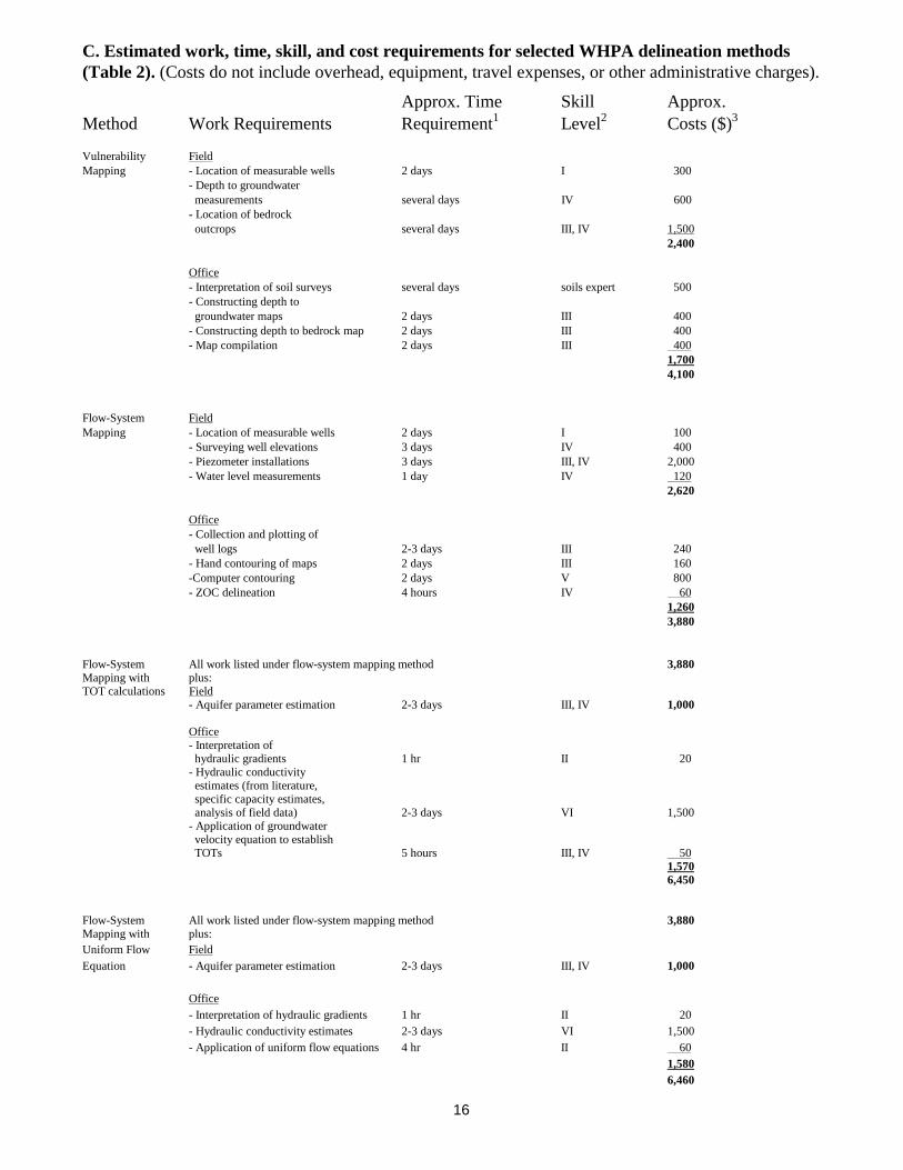
Exact prediction of the costs inherent in each of the methods is difficult because the amountof field work required for each method depends on how much information is already available, thecomplexity of the problem area, and the degree of accuracy desired by the wellhead protectionprogram. For example, the work required for aquifer parameter estimation can range from the leastcostly and least accurate method of simply citing the average values of parameters (such as hydraulicconductivity or porosity) found in literature to the most costly and most accurate method ofperforming a pumping test. The latter requires extensive field work and many hours of technical dataanalysis. The parameters necessary for each ZOC delineation method are included in Table 1. Table2 summarizes some of the work, time, skill, and approximate cost requirements of performing theindividual tasks for each of the methods.
The cost estimates are primarily based on an hourly rate that represents the actual salary to anindividual at a particular skill level. It does not include general overhead, benefits, taxes, profit, orthe amortization of equipment. If a consultant were employed to perform the same tasks, s/he wouldusually charge three times the hourly costs that are listed in Table 2. Six groundwater consultants orconsulting firms in Wisconsin were contacted regarding typical costs for this type of work. Theywould charge $40 to $100/hr for tasks with skill levels IV, V, and VI. The cost of the flow-systemmapping method with calculations (but without drilling or monitoring-well installation) probablywould be between $10,000 and $20,000.
B. Data requirements for WHPA delineation methods (Table 1)
Method _____________________Data Requirements_________________________________________Hydrologic Aquifer
K V Q n i b S R Boundaries Geometries
Vulnerability Geologic, soils, and water-table mapsMapping Field mapping of surficial features
Flow-System Mapping X X
Flow-System Mapping with TOT X X X X X
with Uniform Flow Equation X X X X X X X
Residence Time Water sampling and analyses
Semi-analytical Flow/Particle-Tracking Tools X X X X X
Numerical Flow/Transport Model X X X X X X X X X
Explanation:
K = hydraulic conductivity i = hydraulic gradientV = vertical leakance b = aquifer thicknessQ = well pumping rate S = storativityn = porosity R = recharge rate
16
C. Estimated work, time, skill, and cost requirements for selected WHPA delineation methods(Table 2). (Costs do not include overhead, equipment, travel expenses, or other administrative charges).
Approx. Time Skill Approx.Method Work Requirements Requirement1 Level2 Costs ($)3
Vulnerability FieldMapping - Location of measurable wells 2 days I 300
- Depth to groundwater measurements several days IV 600- Location of bedrock outcrops several days III, IV 1,500
2,400
Office- Interpretation of soil surveys several days soils expert 500- Constructing depth to groundwater maps 2 days III 400- Constructing depth to bedrock map 2 days III 400- Map compilation 2 days III 400
1,7004,100
Flow-System FieldMapping - Location of measurable wells 2 days I 100
- Surveying well elevations 3 days IV 400- Piezometer installations 3 days III, IV 2,000- Water level measurements 1 day IV 120
2,620
Office- Collection and plotting of well logs 2-3 days III 240- Hand contouring of maps 2 days III 160-Computer contouring 2 days V 800- ZOC delineation 4 hours IV 60
1,2603,880
Flow-System All work listed under flow-system mapping method 3,880Mapping with plus:TOT calculations Field
- Aquifer parameter estimation 2-3 days III, IV 1,000
Office- Interpretation of hydraulic gradients 1 hr II 20- Hydraulic conductivity estimates (from literature, specific capacity estimates, analysis of field data) 2-3 days VI 1,500- Application of groundwater velocity equation to establish TOTs 5 hours III, IV 50
1,5706,450
Flow-System All work listed under flow-system mapping method 3,880Mapping with plus:Uniform Flow FieldEquation - Aquifer parameter estimation 2-3 days III, IV 1,000
Office- Interpretation of hydraulic gradients 1 hr II 20- Hydraulic conductivity estimates 2-3 days VI 1,500- Application of uniform flow equations 4 hr II 60
1,5806,460

17
Residence-Time FieldApproach - Water sampling 2 days IV 300
Laboratory- Sample analyses - chem lab 3,000
Office- Data interpretation 2 days VI 1,200
4,500
Semi-analytical All work listed under flow-system mapping method 3,880Flow/Particle- plus:Tracking Models Office
- Interpretation of hydraulic gradients 1 hr III 10- Determine well coordinates 2 hr II 15- Determine pumping rates 2 hr II 15-Modelling 4 hr V 200
2404,120
Numerical FieldModelling Might include:
- Location of measureable wells 2 days I 100- Surveying well elevations 3 days IV 400- Water level measurements several days IV 500- Piezometer installation 3 days III, IV 2,000- Borehole drilling and logging 1 week III, IV 15,000- Geophysical logging several days III, IV 5,000- Video logging 1 day IV 1,000- Slug tests 1-2 weeks IV 1,500- Aquifer pumping test 2 days III, IV 2,000- Location of bedrock outcrops 2 days III, IV 500
28,000
Office- Water table mapping 1 week III 500- Bedrock surface elevation mapping 2 days III 200- Analysis of field data: 2-3 weeks 5,000
- Slug tests VI- Geophysical logs III- Pumping test VI- Borehole drilling III
- Initial model construction 3 weeks VI 9,000- Parameter selection- Boundaries- Spatial discretization (horizontal and vertical)- Data management
- Model calibration 2 weeks VI 6,000- Transient simulations 1 week VI 3,000- Application of particle tracking program to delineate ZOC 2 weeks VI 6,000- Preparation of graphic output 1 week V 2,000
31,700 59,700

18
1Time requirements depend on the scale and complexity of the problem.Hourly
2 Skill Level: Rate ($)I - Little or no technical expertise required 5II - Some knowledge of hydrogeology helpful 7.50III - Training in hydrogeology and/or mapping required 10IV - Training in hydrogeologic field methods required 15V - Computer expertise required 50VI - Requires combination of computer and hydrogeologic expertise
3 Costs do not include overhead, equipment, travel expense, and other administrativecharges.

19
Decisions which can result in groundwater pollution or protection are made by individualpeople. They decide to install a septic system, fertilize their yard or garden, start a feedlot,open a gas station, improve an industrial process, reduce waste or recycle and many otheractivities. People can make better decisions if they understand the impact of their actions.Wellhead protection is a tool that is designed to minimize the potential for groundwatercontamination to occur. Protection, management and education are the tools used by asuccessful wellhead protection program. Many groups and individuals need to cooperate.People getting involved - as citizens, agency staff, local leaders and industryrepresentatives - will supply the energy to make wellhead protection work. Take positiveand progressive steps to protect the quality of life that your community now enjoys.
VIII. For more information about wellhead protection contact:
1. DNR New Well Wellhead Protection Coordinator Lee BoushonPublic Water Supply SectionP. O. Box 7921Madison, WI 53707-7921(608) 266-0857email: [email protected]
2. DNR Voluntary Wellhead Protection Coordinator David LindorffGroundwater SectionP. O. Box 7921Madison, WI 53707-7921(608) 266-9265 or (877) 268-9355 toll freeemail: [email protected]
3. DNR Regional Water Supply Specialists
Northeast Region South Central Region1125 N Military Avenue 3911 Fish Hatchery RoadBox 10448 Fitchburg, WI 53711Green Bay, WI 54307-0488 (608) 275-3266(920) 492-5800
Southeast Region West Central Region2300 N Dr. Martin Luther King Jr Dr 1300 W Clairemont AvenueP O Box 12436 P O Box 4001Milwaukee, WI 53212 Eau Claire, WI 54702-4001(414) 263-8500 (715) 839-3700
Northern Region Northern Region810 W Maple Street 107 Sutliff AvenueSpooner, WI 54801 Rhinelander, WI 54501(715) 635-2101 (715) 365-8900
4. The Wisconsin Geological and Natural History Survey (WGNHS) can provideinformation on what type of geological and hydrogeological data are available for yourarea. For a list ofWGNHS publications, write or call:

20
Wisconsin Geological and Natural History Survey3817 Mineral Point RoadMadison, WI 53705(608) 262-1705
5. The Central Wisconsin Groundwater Center is a clearinghouse for information ongroundwater issues in central Wisconsin.
Central Wisconsin Groundwater CenterCollege of Natural Resources, room 224University of Wisconsin - Stevens PointStevens Point, WI 54481(715) 346-4270
6. The Wisconsin Rural Water Association (WRWA) provides technical assistance torural communities (with water supplies that serve 10,000 people or less) that are trying toestablish WHP programs.
Wisconsin Rural Water Association350 Water Way
Plover, WI 54467
(715) 344-7778
7. Your county University of Wisconsin - Extension office can provide generalinformation on wellhead protection. Look for the address and phone number in thetelephone book under the county listings.
8. The National Technical Information Service can provide you with the EPApublications. There may be a cost.
National Technical Information ServiceU. S. Department of CommerceSpringfield, VA 221611-800-553-6847

21
REFERENCES
Wisconsin Department of Natural Resources Publications:
Groundwater: Protecting Wisconsin’s Buried Treasure: Supplement to Wisconsin NaturalResources Magazine, 1999, 32 p.
Wisconsin Geological and Natural History Survey Publications:
A Guide to Groundwater Quality Planning and Management for Local Governments: Wis.Geological and Natural History Survey Spec. Rept. 9, 1987, 91 p.
Wellhead Protection Districts in Wisconsin: An Analysis and Test Applications. Special Report 10,1988, 75 pages.
Groundwater Protection Through Local Land-Use Controls. Special Report 11, 1991, 48 p.
Water Table Maps. Miscellaneous Papers, 81-1.
United States Environmental Protection Agency Publications:
Guidelines for Delineation of Wellhead Protection Areas: U.S. EPA Office of Ground-WaterProtection, Chapters paginated separately, June, 1987.
Wellhead Protection Programs: Tools for Local Governments: U.S. EPA, Office of Ground-WaterProtection, 1989, 50 p.
Protecting Local Groundwater Supplies Through Wellhead Protection: U.S. EPA, Office of Water,1991, EPA 570/9-90-007, 18 p.
Delineation of Wellhead Protection Areas in Fractured Rocks. U.S. EPA Technical GuidanceDocument, Written by K. R. Bradbury, M. A Muldoon and A. Zaporozec. USEPA Office of Water,(June 1991) EPA 570/9-91-009, 144 p.
Wellhead Protection Strategies for Confined Aquifer Settings. USEPA Office of Water, June 1991,(EPA 570/9-91-008) 168 pages.

ANNOTATED BIBLIOGRAPHY
WISCONSIN PUBLICATIONS
Designs for Wellhead Protection in Central Wisconsin - Case Studies in the Town of Weston andCity of Wisconsin Rapids. Thomas J. Osborne, et al. (1989).
Wellhead protection basics. WHPA delineation, time of travel calculations, potentialcontamination sources, and designing groundwater protection strategies. Available from theCentral Wisconsin Groundwater Center. 95 pages. (715) 346-4270 $4.50
A Guide to Groundwater Quality Planning and Management for Local Governments. StephenM. Born et al. (1987).
Detailed discussion on the individual steps in the wellhead protection process. The discussionon regulatory and nonregulatory tools is particularly good. Available from the WisconsinGeological and Natural History Survey (WGNHS), (608) 263-7389; (Ask for Spec. Rept. 9).91 p., $5.00
Wellhead Protection Districts in Wisconsin: An Analysis and Test Applications. Stephen M.Born et al. (1988).
Reviews various methods for delineating wellhead protection districts and assesses themethods in a variety of settings representative of Wisconsin’s hydrogeology. This publicationmay be the best single source of information concerning wellhead protection. Available fromthe WGNHS, $3.00.
Groundwater Protection Through Local Land-Use Controls. Douglas A. Yanggen and BruceWebendorfer. (1991).
Focuses on how local governments can use zoning and subdivision control powers to regulatethe land uses that may contaminate groundwater. It is designed as a guide for elected officials,planning and zoning officials, and their technical advisors. Available from the WGNHS, 48pages. (608) 263-7398; (Ask for Spec. Rept. 11) $4.00
Groundwater Quality Regulation: Existing Governmental Authority and Recommended Roles.Douglas M. Yanggen and Leslie L. Amrhein. (1989).
Focuses on roles that local governments can play in joint local/state regulatory schemes toprotect groundwater. Intended for persons preparing local regulations and their legal advisors.Available from the WGNHS, 109 pages. (608) 263-7398 $6.00
EPA GUIDANCE DOCUMENTS AND OTHER PUBLICATIONS
Guidelines for Delineation of Wellhead Protection Areas: U.S. EPA, Office of GroundwaterProtection, Washington, DC, (1987).
Identifies and describes the various methods used to delineate a wellhead protection area. USEPA Office of Groundwater Protection, Washington, D.C. Separate chapters.
Protecting Loca1 Groundwater Supplies Through Wellhead Protection (May, 1991).

Intended to be used by city or town officials, water supply managers or interested citizens. Itcontains a five step procedure to help you delineate, inventory, and manage your local wellheadprotection area. 18 pages. EPA Document 570/9-91-007.
Groundwater: Managing the Unseen Resource. Edwin H. Clark II and Philip J. Cherry. (1992).This handbook attempts to point out the most innovative and effective programs ingroundwater protection and temper expectations with cautionary notes on problemsencountered in other areas or programs. Available from the World Wildlife Fund Publications,P.O. Box 4866, Hampden Post Office, Baltimore, MD. 21211. (419) 516- 6951. $8.50 34Pages.
A Review of Sources of Groundwater Contamination from Light Industry (May 1990).This Technical Assistance Document is intended to assist managers and officials in identifyingand controlling potential light industrial sources of contamination that may pose a threat topublic water supplies. 48 pages. EPA Document 440/6-90-005.
Local Financing for Wellhead Protection (June 1989).
Provides information to state and local managers of water supplies about financing available tosupport wellhead protection programs. 57 pages. EPA Document 440/6-89-002.
Wellhead Protection Programs: Tools for Local Governments (April 1989)A Technical Assistance Document to be used as a reference source by planners and officialswhen they are looking for ways to manage their wellhead protection areas. 50 pages. EPADocument 440/6-89-002.
Developing A State Wellhead Protection Program: A User’s Guide to Assist State AgenciesUnder the Safe Drinking Water Act (July 1988).
This Technical Document outlines the range of options available and examples of differentapproaches that can be used to develop each element of a wellhead protection plan. 44 pages.EPA Document 440/6-88-003.
Surface Geophysical Techniques for Aquifer and Wellhead Protection Area Delineation(December 1987).
This Technical Assistance Document details one scientific approach to delineation of wellheadprotection areas. It may be appropriate for groundwater system managers. 49 pages. EPADocument 440/12-87-016.
An Annotated Bibliography on Wellhead Protection Programs (August 1987).
Contains references on 142 documents that contain one or more of the six statutorily requiredelements of a wellhead protection program. 75 pages. EPA Document 440/6-87-004.