developing multimedia land record systems (url: … · developing multimedia land record systems...
TRANSCRIPT

UCGE Reports Number 20283
Department of Geomatics Engineering
Developing Multimedia Land Record Systems (URL: http://www.geomatics.ucalgary.ca/research/publications)
by
Abdel Rahman Muhsen
January 2009

UNIVERSITY OF CALGARY
Developing Multimedia Land Record Systems
by
Abdel Rahman Muhsen
A THESIS
SUBMITTED TO THE FACULTY OF GRADUATE STUDIES
IN PARTIAL FULFILMENT OF THE REQUIREMENTS FOR THE
DEGREE OF MASTER OF SCIENCE
DEPARTMENT OF GEOMATICS ENGINEERING
CALGARY, ALBERTA
JANUARY, 2009
© Abdel Rahman Muhsen 2009

ii
Abstract
Conventional cadastral and land information systems are seldom designed to cater for
situations where official recognition of land tenure is uncertain. Uncertainty emerges
because conventional instruments, e.g. land titles, do not accurately mirror conditions on
the ground in many of these situations. Such situations include customary tenure areas,
informal settlements, and post-conflict situations. There is a need for flexible land
information system (LIS) software that can cope with uncertainty, is adaptable to the
changing conditions, and allows rapid data collection at a local level.
This thesis proposes a methodology that guides the development of LIS software
in the aforementioned situations. The research has identified the evolutionary approach as
an appropriate strategy to be adopted and used as the basis of the methodology. Hence, a
flexible initial system that incorporates multimedia data has been developed. This initial
system can evolve over time to accommodate the uncertainty and changing requirements
which characterize the situations addressed.

iii
Acknowledgements
This thesis could not have been completed without the grace of God. All thanks are due
to Him.
I also would like to express my sincere gratitude to my supervisor, Dr. Michael
Barry, for his continuous support and guidance. I learned a lot from him. He has always
been a source of inspiration for tackling research problems from a different perspective.
The experience I had with him is priceless.
Throughout the writing of this thesis, I received immense support and
encouragement from many people. These people include friends and colleagues whom I
am really fortunate and proud of having. I am indebted to Tracy Timmins, Yaser
Ghanam, Lani Roux, Mohammed Soliman, Sandy Hafez, Marwan Abdeen, and Alaa
Kassab. Without the help of all these people, this thesis would have certainly been of
lesser quality. Thank you!
I am most grateful to Alberta Land Surveyor’s Association (ALSA) and the
Holmlund family for their financial support. Without their generosity, this research would
not have been possible.
Last but not least, deep gratitude goes to my family for the endless emotional
support. I miss you very much.

iv
Dedication
To my mother, my wife, and my unborn child!
Inspired by a customary tenure belief which states that land does
not belong to individuals; rather, it belongs to many generations:
the dead, the living, and the unborn.

v
Table of Contents
Approval Page ..................................................................................................................... ii
Abstract ............................................................................................................................... ii
Acknowledgements ............................................................................................................ iii
Dedication .......................................................................................................................... iv
Table of Contents .................................................................................................................v
List of Tables .................................................................................................................... vii
List of Figures and Illustrations ....................................................................................... viii
List of Symbols, Abbreviations and Nomenclature ........................................................... ix
CHAPTER ONE: INTRODUCTION ..................................................................................1
1.1 Introduction ................................................................................................................1
1.2 Problem Definition ....................................................................................................2
1.3 Significance ...............................................................................................................3
1.4 Uncertain Situations ...................................................................................................5
1.5 Research Objectives ...................................................................................................7
1.6 Research Questions ....................................................................................................8
1.7 Research Method .......................................................................................................8
1.8 Data ..........................................................................................................................10
1.9 Scope and Limitations .............................................................................................11
1.10 Contribution to Knowledge ...................................................................................12
1.11 Organization of the Document ...............................................................................13
1.12 Chapter Summary ..................................................................................................13
CHAPTER TWO: CADASTRAL BACKGROUND ........................................................14
2.1 Introduction ..............................................................................................................14
2.2 Land Administration ................................................................................................14
2.3 Land Tenure .............................................................................................................16
2.3.1 Customary tenure .............................................................................................18
2.3.2 Private tenure ...................................................................................................18
2.3.3 Public tenure ....................................................................................................18
2.3.4 Religious land tenure .......................................................................................18
2.3.5 Informal tenure ................................................................................................18
2.4 Cadastral Systems ....................................................................................................20
2.5 Land Tenure in Customary, Peri-urban, and Post-conflict Areas ............................24
2.5.1 Customary tenure areas ...................................................................................25
2.5.1.1 First peoples ..........................................................................................26
2.5.2 Peri-urban areas ...............................................................................................28
2.5.3 Post-conflict areas ...........................................................................................29
2.6 Related Work: Current initiatives in cadastral modelling .......................................31
2.6.1 The Core Cadastral Domain Model (CCDM) .................................................31
2.6.2 The Social Tenure Domain Model (STDM) ...................................................40
2.7 Chapter Summary ....................................................................................................45
CHAPTER THREE: SOFTWARE DEVELOPMENT APPROACHES ..........................47
3.1 Introduction ..............................................................................................................47

vi
3.2 Software Development Approaches ........................................................................47
3.2.1 The waterfall model .........................................................................................48
3.2.2 The spiral model ..............................................................................................50
3.2.3 Prototyping ......................................................................................................53
3.2.4 Iterative, incremental and evolutionary development .....................................55
3.3 The Adopted Approach ............................................................................................57
3.4 Chapter Summary ....................................................................................................58
CHAPTER FOUR: A METHODOLOGY FOR LIS SOFTWARE DEVELOPMENT
IN UNCERTAIN SITUATIONS ..............................................................................59
4.1 Introduction ..............................................................................................................59
4.2 The Methodology .....................................................................................................60
4.2.1 The initial system ............................................................................................62
4.2.1.1 The initial design: the three-class model ...............................................63
4.2.1.2 An initial prototype for data collection ..................................................69
4.2.2 System analysis ...............................................................................................71
4.2.3 System evolution .............................................................................................72
4.2.4 Data migration .................................................................................................76
4.3 Chapter Summary ....................................................................................................77
CHAPTER FIVE: SOFTWARE IMPLEMENTATION AND TESTING ........................78
5.1 Introduction ..............................................................................................................78
5.2 Software Implementation .........................................................................................78
5.2.1 The database ....................................................................................................79
5.2.2 The software user-interface .............................................................................81
5.3 Testing .....................................................................................................................83
5.3.1 Testing the OM software .................................................................................83
5.3.2 Testing the methodology .................................................................................87
5.4 Chapter Summary ....................................................................................................91
CHAPTER SIX: CONCLUSIONS AND FUTURE WORK ............................................92
6.1 Introduction ..............................................................................................................92
6.2 Conclusions ..............................................................................................................93
6.3 Future Work ...........................................................................................................100
6.4 Chapter Summary ..................................................................................................101
REFERENCES ................................................................................................................102
APPENDIX A: LADM UML CLASS DIAGRAM .................................................................109
APPENDIX B: STDM UML CLASS DIAGRAM .................................................................114
APPENDIX C: TALKING TITLER OBJECT MANAGER SOFTWARE REQUIREMENT
DOCUMENT ............................................................................................................116
APPENDIX D: TALKING TITLER OBJECT MANAGER SOFTWARE TUTORIAL...........144

vii
List of Tables
Table 5.1. Software license list ......................................................................................... 87

viii
List of Figures and Illustrations
Figure 2.1. Land Administration (Barry 1999) ................................................................. 16
Figure 2.2. The continuum of land tenure system (after (Barry 2008c)) .......................... 17
Figure 2.3. Cadastral System (after (Barry 1999)) ........................................................... 21
Figure 2.4. The core of the LADM: Person, RRR, and RegisterObject (taken from
(ISO /TC211 N2385 2008, fig. 1)) ............................................................................ 34
Figure 2.5. RRR specialization in CCMD. Restriction is a View (taken from (van
Oosterom et al. 2006, fig. 9)) .................................................................................... 39
Figure 2.6. RR class specializations ................................................................................. 40
Figure 2.7. The core of the STDM, taken from (Lemmen et al. 2007, figure 1) .............. 42
Figure 3.1. The waterfall model (after (Leffingwell and Widrig 2003)) .......................... 49
Figure 3.2. The spiral model (taken from (Boehm 1988)) ................................................ 52
Figure 4.1. High-level view of LIS software methodology .............................................. 61
Figure 4.2. High-level conceptual view of the three-class model. .................................... 63
Figure 4.3. Generalized classes with example of possible types. ..................................... 68
Figure 4.4. Media Auxiliary Attributes............................................................................. 69
Figure 4.5. The 4-class model. .......................................................................................... 74
Figure 4.6. Specializations of Reference Instrument class. .............................................. 75
Figure 5.1. The OM Physical Model. ............................................................................... 81
Figure 5.2. The OM User-interface................................................................................... 82
Figure 5.3. High-level conceptual model of the evovled system ...................................... 89

ix
List of Symbols, Abbreviations and Nomenclature
Symbol Definition
CCDM Core Cadastral Domain Model
DBMS Database Management System
ECS The Environmental Centre for Swaziland
ETL Extract, Transform, and Load
FIG International Federation of Surveyors
GIS Geographical Information System
GUI Graphical User Interface
INSPIRE Infrastructure for Spatial Information in Europe
ISO International Organization for Standardization
LADM Land Administration Domain Model
LIS Land Information System
NGO
Non-Governmental Organization
UML Unified Modelling Language
STDM Social Tenure Domain Model
VB.NET Visual Basic .NET

1
Chapter One: Introduction
1.1 Introduction
Security of tenure is a major factor underlying social, economic and cultural
development. Land titling programmes and conventional cadastral systems are a means of
achieving this goal (i.e. security of tenure). However, conventional systems are not
appropriate for all situations (Augustinus, Lemmen, and van Oosterom 2006).
Innovative land tools that can uphold the security of tenure in particular situations
are needed. These situations are customary tenure systems, informal settlements, and
post-conflict situations. In such situations, conventional cadastral systems, such as land
registration and cadastral surveys, often fail to achieve the objectives underlying their
implementation (Muhsen and Barry 2008). Primarily, they fail to secure people’s rights in
land. Sometimes, they may even do more harm than good; in that they may exacerbate or
catalyse a conflict in a situation or they may diminish or threaten the security of tenure of
some people (Barry 2008d). For example, conventional cadastral and registration systems
may render vulnerable particular groups in a society (e.g. women, the elderly) landless as
they extinguish their de facto rights and place greater legal power in the hands of the
registered owner than existed prior to registration (Barry 2008d).
This thesis aims to develop a methodology that informs the development of such
innovative land tools that can alleviate the situations mentioned above in terms of
supporting and increasing land tenure security.

2
1.2 Problem Definition
In particular situations conventional cadastral systems, i.e. land registration and cadastral
survey systems are not appropriate functional systems to support land tenure security
(UN-Habitat 2008:20; Cousins et al. 2005:5). In many of these “uncertain situations” (see
Section 1.4) they do not produce the anticipated outcomes, tend to fall into disuse, may
be manipulated by powerful elites, or do not model the de facto situation on the ground
adequately (Barry 2008d). A number of phenomena may underlie this:
1. Conventional land registration is based on concepts imported from Western
societies (Lamba 2005). In essence, it draws on the model of individual parcels
and individualized tenure (Augustinus, Lemmen, and van Oosterom 2006:2). In
many situations, this is culturally inappropriate. For instance, if land is held by
family or lineage groups, it may be inappropriate to divide it up into individual
lots, or there may be overriding community rights in a parcel which are superior
to those of the land holder (Barry 2008c).
2. Further, registration relies on instruments that might not match the manner in
which a situation operates. For example, registration depends on written evidence.
However, oral tradition forms the basis of land tenure systems in many societies
(Barry and Khan 2005).
3. Registration is expensive and time consuming, which may prevent poor
communities from using and benefitting from it, leading them to use the informal
market to conduct land transactions (UN-Habitat 2004:24).
4. Efficient registration requires well established institutions operating under clear
legislative frameworks and following established land administration policies and

3
procedures (van der Molen and Lemmen 2004). These institutions do not always
exist, such as in situations of political and social unrest.
There is a need for alternative land information systems (LIS) which differ from
conventional land registration and cadastral surveying to support land tenure security.
Information systems that can model the complex relations between people and land are
required. They should incorporate data at the local level and include social relations, the
oft unwritten land transactions and relationships, and data which people on the ground
can understand. The system should be sufficiently flexible to capture a variety of
different data types, which when linked together, may create a complete picture of the
tenure system on the ground. Further, it becomes clear that a need for a system that is
culturally neutral, is able to recognize and record traditional and customary practices and
give effect to the de facto rights is vital (Muhsen and Barry 2008). This system should
not impose predefined notions onto the existing situation. It should collect data pertaining
to tenure as is, without intervening.
1.3 Significance
This research is significant due to the importance of the problem it is attempting to
alleviate, namely the problem of insecurity of tenure in particular situations resulting
from the lack of appropriate land information systems.
Insecurity of tenure hampers development and prevents many other benefits
arising from security of tenure. Security of tenure acts as a springboard for various
benefits leading to significant economic, social, and political developments. It assists in

4
poverty reduction; facilitates access to credit from financial institutions (e.g. banks);
encourages investment, economic growth; and also promotes social stability by reducing
uncertainty and disputes over land (UN-Habitat 2008).
Further, this research is highly relevant as a significant portion of the world’s
population suffer from insecurity of tenure. As will be described later in Section 2.5, this
research specifically addresses the insecure tenure positions of people in customary
tenure\rural areas, including indigenous peoples; informal settlement and slum dwellers;
and people in post-conflict situations. The scale of this problem is large as approximately
1 billion people live in slums (UNFPA 2007). Also, it is anticipated that the number of
slum dwellers will rise to reach one-third of the world’s population by the year 2030
(Lemmen et al. 2007:3). There are also 300 million indigenous people in more than 70
countries who share the problem of protecting their rights in land (United Nations High
Commission on Human Rights 2003). Moreover, one million farm dwellers have been
evicted since 1994 in South Africa (Cousins et al. 2005; Wegerif, Russell, and Grundling
2005). Thus, there is a significant potential for this research to assist in the improvement
of tenure security of millions of people worldwide.
The scale and severity of the tenure insecurity problem has led to the widely
recognized need to develop alternative solutions to secure land tenure rights, hence
several current and parallel initiatives are in place with the similar objective of achieving
tenure security. For example, Cousins and others (2005) suggest that security of tenure is
achieved by applying solutions that support the existing social practices rather than
replacing them with expensive new systems. Current initiatives, such as the development
of the Social Tenure Domain Model (STDM) (Lemmen et al. 2007), aim to include social

5
relations and tenure types that are not based on a cadastral parcel. The STDM is designed
to address areas with limited cadastral coverage, rural, informal settlements and post-
conflict areas. New approaches have been introduced within various countries and
jurisdictions, such as Mozambique and Uganda, in an attempt to incorporate customary
rights in formal systems (Lemmen et al. 2007). In Namibia, the government proposed the
so-called Flexible Land Tenure System (Christensen 2004) in which special registration
systems operate in parallel with official land registries to secure informal settlers’ rights
in a simple and affordable manner. Similar approaches have been implemented in
Tanzania and Ethiopia (Lemmen et al. 2007).
This research thesis thus complements existing initiatives by providing an
alternative strategy for developing tools to secure land tenure. It is hoped that the
methodology developed here can be adopted and adapted by governments and non-
governmental organizations (NGOs) for implementation in various tenure situations. This
methodology, in essence, represents the contribution of this research.
1.4 Uncertain Situations
In general, this research aims to address unusual situations for which conventional land
registration and cadastral survey systems are seldom designed. These circumstances
include emergency situations following a natural disaster such as a tsunami, post-conflict
situations, societies where oral traditions rather than written records underlie the land
tenure system. Peri-urban areas in the developing world where land tenure practices draw
on customary traditions and western legal practices. As well as poor communities who
cannot afford registration, and situations where power relations in a community (e.g.

6
gangs and similar mutually supportive cliques) place ordinary people under threat
(Muhsen and Barry 2008).
These situations are very diverse. For the sake of simplicity, the author chooses the
term ‘uncertain situations’ to refer to these situations. This term comes from previous
work of Barry (1999). The term is chosen because uncertainty is a common attribute that
characterizes the situations addressed.
Uncertainty in these situations can be described from two standpoints:
(i) From a land tenure perspective which means that land tenure itself is
ambiguous. In other words, there is no absolute clarity on who has rights
to what. That is, the description of the relationship between people and
land is unclear in terms of who, where and what type (Lemmen et al.
2007).
(ii) From an information technology perspective; in that, how the tenure
system should be modelled in an information system is uncertain.
Uncertainty in land tenure may originate from a lack of evidentiary legal
documents (e.g. title) because they are not used and\or substituted by other means. For
example, in customary tenure areas, legal documents are often substituted by oral
traditions. This results in uncertainty in land tenure for land administration authorities
and officials. Moreover, uncertainty may be created when legal documents are destroyed
or are no longer valid or recognized due to a natural disaster or social instability. Also,
uncertainty may arise because of inadequacy inherent in conventional legal documents. In
particular, they do not mirror the situations on the ground (de facto rights) accurately,
leaving a considerable amount of confusion in the tenure system (Barry and Fourie 2002).

7
Uncertainty from an information technology point of view occurs because of a lack
of understanding of the nature of land tenure or simply because there is no consensus
among stakeholders on the requirements for how tenure should be modelled.
There is a need for a LIS that is able to deal with the uncertainty of these situations.
It should accommodate the ambiguity and lack of understanding of land tenure in order to
be able to record land tenure information in uncertain situations. This information may be
extremely useful when the situations stabilize and uncertainty unravels.
1.5 Research Objectives
This research addresses one primary objective, namely:
To contribute to the development of a methodology for
developing land information system (LIS) software for
uncertain situations.
To provide focus to the above objective, the author also aims to develop a system of
software that follows the methodology developed in this research.
There are four secondary objectives which serve as prerequisites for the primary
objective:
a. To investigate the characteristics of land tenure in uncertain situations.
b. To identify an appropriate software development approach which is suitable
for uncertain situations.
c. To develop and test a flexible and evolving cadastral data model that suits
uncertain situations.

8
d. To incorporate multimedia as an unconventional tool and instrument that
allows flexible and quick data capture in uncertain situations.
1.6 Research Questions
In correspondence with the research problem and the primary objective mentioned earlier
in Section 1.2 and 1.5 respectively, the primary question of this research is not why
conventional cadastral and registration systems fail in uncertain situations. But, the
question is how alternative land tools (in particular LIS software), which can alleviate
and improve tenure security of people in uncertain situations, can be developed. An
informed answer to this question is to create or adopt an appropriate methodology which
informs the development of such land tools.
In short, the following questions underlie many of the activities which contribute to
this study:
• What are the characteristics of uncertain situations with regard to land tenure?
• What software development approaches are available?
• Which one of these approaches is most suitable for LIS development in
uncertain situations?
• What is an appropriate design for a cadastral model?
• What are the requirements of a cadastral model which makes it suitable to
cater for uncertain situations? How can they be achieved?
• How can multimedia data be incorporated in land tenure information systems?
1.7 Research Method
In order to achieve the above objectives, the following activities were carried out:

9
1. Literature Review: There are four aspects to this, namely:
i. Conduct a review of general literature relating to cadastral systems to
understand the problems of cadastral systems in general, e.g. the FIG
Statement on the Cadastre (FIG 1995), and Cadastre 2014 (Kaufmann and
Steudler 1998). Particular attention was paid to the status of cadastral
systems in rural areas, informal settlements and post-conflict situations.
ii. Examine current and on-going cadastral domain modelling initiatives,
such as the Core Cadastral Domain Model (van Oosterom et al. 2006) and
the Social Tenure Domain Model (Lemmen et al. 2007). These models are
reviewed and critiqued in Section 2.6 (Related work: Current initiatives in
cadastral modelling).
iii. Analyze literature concerning information systems planning and software
development approaches, especially when system requirements are ill-
defined and are not fully understood (see Chapter 3).
iv. Examine existing research in the Land Tenure and Cadastral Systems
group at the University of Calgary which includes projects in Canada’s
First Nations lands, South Africa, Nigeria and Somaliland.
2. Study current operating cadastral systems: This involves observing
existing systems implemented in different land registry organizations such as
the system of cadastral survey and land registration in Alberta.
3. Conduct interviews with land surveyors and IT professionals: Interview
personnel who work with these systems on a daily basis to obtain valuable
information about various system design features. Also, conduct interviews

10
with information technology (IT) professionals and software engineering
experts to discuss best practices of model design and proper approaches for
information systems development.
4. Design a multimedia cadastral data model: A starter simple cadastral model
is developed. This model incorporates multimedia in addition to conventional
cadastral data. The multimedia model should be characterized by simplicity
and flexibility.
As with any effective information system, the design should result in
solutions which are easy to use and perceived as useful by user communities.
It should ensure that the records are secure and that the system is effective and
efficient in addressing user requirements.
5. Build software to test the developed model: Based on the newly developed
model, prototype software is built, namely: The Object Manager. The Object
Manager is developed using Microsoft Visual Studio 2005. The software is
handed to potential users to use it and populate it with data.
6. Perform model analysis and evaluation: This includes a critique of the
model, through the feedback obtained from parties who used the system or
viewed system demonstrations. The design of the software is refined
accordingly.
1.8 Data
The developed model and prototype was populated with data from different sources. The
data was acquired from local and international agencies. Local agencies include Alberta

11
Land Titles. International data was captured from research done by the Land Tenure and
Cadastral Systems group at University of Calgary in South Africa, Nigeria and
Somaliland. Moreover, additional data was simulated for the purpose of this research.
1.9 Scope and Limitations
The author is aware that a realization of a complete solution to this research problem is
very difficult to attain. A solution for such a complex problem requires new policies,
regulations, land reform programs, and changes in the current legal and administrative
frameworks. However, this research attempts to assist in alleviating this problem from a
technical perspective only by contributing to the development of software tools and data
structures.
This research is limited in its contextual scope to include only informal
settlements, customary tenure areas, and post-conflict situations out of the wide variety of
uncertain situations (see Section 2.5).
Thorough evaluation of the methodology developed in this research is beyond the
purview of this thesis. Ideally, the methodology should be tested in a real life uncertain
situation. Unfortunately, this is very difficult to accomplish, especially within the time
frame available for this research. However, the software has been licensed and tested by
several land sector agencies, NGOs, lawyers and researchers. This includes the: Surveyor
General of Canada and UN-Habitat. Additionally, the software is presently being used by
the Directorate of Land Regularization in Lagos, Nigeria,
This is a multidisciplinary research project as it combines land studies and
cadastral systems research with research from computer science, software engineering

12
and information systems development. Also, this study builds on a previous research by
Barry (Barry 2008d; Barry and Khan 2005; Barry 2006a; Barry et al. 2002) which
affirms the usefulness of incorporating multimedia data in land information systems.
However, this study does not investigate methods for incorporating multimedia data
efficiently from a computer science standpoint.
1.10 Contribution to Knowledge
An evolutionary approach has been adopted as a basis for the methodology developed in
this research (see Chapter 4). From the literature review, it is evident that to date, this
approach has not been used extensively in cadastral systems development. Unlike others,
the paradigm used in this research assumes that a prior knowledge of the appropriate
design (data structure) to model land tenure information is not available, and this design
can be achieved by several iterations and refinements to an initial, general design.
Further, this research incorporates multimedia data in land information systems to
improve their currency and completeness. No similar research using multimedia data in
the cadastral domain has been identified to date.
Perhaps, the major contribution of this research is manifested by testing the
viability of using an evolutionary approach in cadastral systems development through
designing and developing LIS software that augments conventional evidence with
multimedia data.
The author’s personal contribution to this research is that he has put the design
discussion among the members of the Land Tenure and Cadastral Systems group at

13
University of Calgary into practice. He developed software for testing the feasibility
and\or possibility of key aspects of the design.
1.11 Organization of the Document
Chapters 2 and 3 provide the conceptual and theoretical background of this research.
Chapter 2 provides the relevant background for cadastral and land tenure systems, while
Chapter 3 discusses the background from an IT perspective. Chapter 4 presents the LIS
software development methodology developed in this research. Chapter 5 discusses the
software implementation and how it was tested. Finally, Chapter 6 summarizes this
research by presenting its conclusions and future work.
1.12 Chapter Summary
This chapter gave a brief introduction to the topic of this thesis. Firstly, it defined the
problem, followed by a discussion of the significance of this research. Further, it
described the situations where this research is applicable (uncertain situations). It stated
the objectives, questions and scope of the research in addition to the data used, and the
method by which this research’s problem is approached. Lastly, the chapters of the thesis
were outlined.

14
Chapter Two: Cadastral Background
2.1 Introduction
This chapter represents the first part of the literature review required for this study. In
particular, it provides a theoretical background for this research from a cadastral
perspective. The chapter aims to help the reader better understand this study and
therefore conceptualizes key terms used in this research and relationships between them.
Also, it discusses the primary area addressed by this research, land tenure in uncertain
situations, and in the process fulfils the secondary objective (a) in Section 1.5: To
investigate the characteristics of land tenure in uncertain situations. Further, it conducts
a critical review of endeavours pertinent to cadastral modelling.
The chapter commences with a discussion of several concepts in the cadastral
domain, namely land administration, land tenure and cadastral systems. Thereafter, it
describes the characteristics of the situations addressed by this research. The chapter then
concludes with related work in which two existing cadastral models are presented.
2.2 Land Administration
In a broad sense, land administration is defined as an operational system designed to
implement land policies. Many definitions are found in the literature endorsing this
meaning. For example, the UN (1996) defines land administration as “the process of
determining, recording, and disseminating information about ownership, value and use of
land when implementing land policies.” Similarly, Barry and Fourie (Barry and Fourie

15
2002) state that "land administration comprises the sub-systems that actualize strategies
to implement land policy, and other related policies, within land management systems."
Land administration is sometimes viewed as the management of land (van der
Molen 2002:365). From this perspective, the term ‘land administration’ is used to refer to
“the processes of regulating land and property development and the use and conservation
of the land, the gathering of revenues from the land through sales, leasing, and taxation,
and the resolving of conflicts concerning the ownership and use of land” (Dale and
McLaughlin 1999).
For this study, the author adopts Barry’s definition (1999) of land administration
as a set of operational sub-systems that puts policies concerning land into action. This
definition implies that the administration of land is not in itself a strategic process. In
particular, land administration does not involve strategic planning or policy development;
rather, it is merely an implementation system that follows regulations and rules stated in
the policies.
Land administration, according to Barry (1999), is depicted in Figure 2.1. The
figure shows a sample of the subsystems that comprise land administration. Each
subsystem fulfils a unique strategic goal and functions to serve a particular purpose;
however, these subsystems are integrated and connected with each other in some way.
For example, building a new street in a transportation network (transportation subsystem)
requires cadastral information to identify land parcels to be expropriated, affected land
owners (tenure subsystem), and values of these parcels (fiscal subsystem). Similar
examples apply for utility supply and environmental conservation programs.

16
Figure 2.1. Land Administration (Barry 1999)
This research focuses on a particular sub-system of land administration, land
tenure (see Figure 2.1), which is therefore described in greater detail in the following
section.
2.3 Land Tenure
A definition of land tenure is provided by Barry and Fourie in (2002:26) as the way in
which land is defined and held. An analogous definition is presented by van der Molen
(2002:265) in which he defines land tenure as “the mode in which rights to land are held
based on statutory law, common law, and customary traditions.” Using the words of
Payne in (2001), land tenure is “the mode by which land is held or owned, or the set of
relationships among people concerning land or its products.”
The latter two definitions do not explicitly include the definition of a land object
(i.e. how people perceive land) as part of the tenure system. In the author’s opinion, the

17
principles which reflect how land is defined are an integral part of land tenure systems.
Certainly, societies with different systems of tenure have different conceptions of the
land object. In fact, to hold rights in land, the rights holder must have a concept
(definition) of that land object. Is it limited to the earth’s surface only? Does it include
the developments on the land, the minerals beneath it, or the fruits it produces?
Another aspect of land tenure is the level of recognition (legitimacy) it holds from
public authorities. Tenure can be regarded as formal and informal. Formal tenure is
usually a legally recognized form of tenure. On the other hand, informal tenure is not
necessarily illegal, but it might evolve outside of the formal legal processes in the form of
contractual or customary arrangements (Dale and McLaughlin 1988:6). Therefore, it is
possible for informal land tenure to become legally recognised over time (Barry
1999:61). However, this categorization of tenure systems as formal and informal (or legal
and illegal) is very simplistic. In the real world, there are complex situations where a
mixture of formal and informal tenure co-exists. Hence, researchers have emphasized the
need to view land tenure on a continuum where formal and informal systems are on
opposite extremes and other forms of tenure systems reside in between (Barry 1999;
Augustinus, Lemmen, and van Oosterom 2006; Payne 2001; The World Bank and Sida
2007; Davies and Fourie 1998). This continuum is portrayed in Figure 2.2.
Figure 2.2. The continuum of land tenure system (after (Barry 2008c))

18
The following presents some of the most common general categories of tenure
according to Payne (2001):
2.3.1 Customary tenure
This form of tenure is based on customary law. It is generally found in hunter-gatherer,
pastoral and agricultural societies. Customary tenure shall be discussed in more detail in
Section 2.5.1.
2.3.2 Private tenure
This form of tenure is most common in urban areas. The holder of this tenure has
(almost) unrestricted use, and the ability to dispose of the land (i.e. sell, or transfer).
Other types of tenure that can be classified under this type are: allodial, freehold and
ownership.
2.3.3 Public tenure
This tenure exists mainly in socialist countries. In this form of tenure, all rights are vested
in the state or in the community as a whole. Land limited to public use, where all citizens
obtain conditional access to land, is also considered public tenure, examples would be
parks and sea shores.
2.3.4 Religious land tenure
This is primarily represented by Islamic tenure systems. Different forms of Islamic
tenure exist in Islamic countries. Islamic tenure systems obtain their land laws from
Sharia, the Islamic religious law.
2.3.5 Informal tenure
This tenure includes different levels of informality; it could be regularized or un-
regularized squatting, illegal subdivision, houses and plots that do not conform to

19
planning regulations, and informal renting. These informal forms of tenure tend to appear
within urban areas and their surroundings.
Relevance to research: The relevance of the above is to show the potential complexity
found in land tenure forms. This complexity and the wide variety of tenure systems found
are caused by the combined influence of social, political, cultural, religious, and
economic factors. To further complicate things, land tenure is dynamic, and different
forms of tenure may co-exist (Payne 2001:417). Considering that part of the primary
objective of this study is to develop land information system software, the above suggests
that flexibility is an essential requirement of effective land record systems. In a more
concrete sense, these systems should be flexible enough to support different forms of land
tenure.
To achieve the ultimate goal of effective land administration, information
pertaining to land (including tenure information) must be collected, analyzed,
documented, and disseminated. All these processes are carried out within a system called
the cadastral system. Designing a cadastral system which can accommodate the wide
variation of existing tenure categories is complex, especially when one attempts to deal
with customary and informal tenure types. According to Lemmen and van Oosterom
(2002), a cadastral system is the environment within which land administration processes
(land registration and cadastral mapping) take place. Cadastral systems are discussed in
the following section.

20
2.4 Cadastral Systems
There is no consensus in the cadastral literature on one universal definition of the term
‘cadastral system’(Lemmen and van Oosterom 2001:320). Furthermore, Silva and
Stubkjaer (2002) note that, most of the time, the meaning of the term ‘cadastral system’
has not been made explicit and its use is typically very loose.
As its main goal, this discussion does not aim to debate the various definitions of
cadastral systems. Instead, it aims to present the definition which clearly explains
cadastral systems as being used by the author in this research. In this study, a cadastral
system is defined as a collection of integrated sub-systems which perform the following
processes: 1) adjudication, 2) boundary definition, demarcation, and surveying, 3)
registration and 4) dispute resolution (Barry 1999:63). As depicted in Figure 2.3, the
cadastral system is constituted primarily of a set of processes (inner doughnut) together
with an information system (IS). These processes are carried out by institutions and are
constrained by the technical and human resources available.
Adjudication, according to Lawrance (1985), is the process of determining rights
in a land unit (i.e. a parcel, or in more general sense, a physical space). The processes of
boundary definition, demarcation, and surveying generally involve marking, measuring
and mapping the limits of a land unit (Dale and McLaughlin 1988:28). Registration is the
official recording of recognized interests in land (McLaughlin and Nichols 1989:81)
whereas dispute resolution is the process of resolving conflicts that may arise over a unit
of land. For further discussions about these processes, the reader is referred to the
references used above.

21
Figure 2.3. Cadastral System (after (Barry 1999))
The institutions are the environment within which cadastral systems operate.
These institutions follow their own regulations, and are given a mandate to carry out
cadastral processes. Cadastral institutions may be formal, e.g. a government department,
or informal, e.g. a tribe leader or a village committee.
Human resources comprise the people who are responsible for operating the
system. These people are required to possess sufficient knowledge and skills to be able to
run and maintain the system. Human resources may include, surveyors, lawyers, mapping
and data entry specialists, and information system specialists.
Technical resources consist of the devices and technologies used to carry out the
system tasks. These include devices that support information management, e.g.

22
computers and digital information storage devices; surveying devices, e.g. GPSs; as well
as communication and networking infrastructures, e.g. the Internet.
Cadastral systems must match the technical and human resources available in a
particular situation in order for it to be appropriate. As stated by Williamson and
Parkville (1996), cadastral systems designed for developing countries should be simple,
flexible, and attainable at low cost. While cadastral systems found in the developed
countries are more complex, rigid, and expensive.
As shown in Figure 2.3, the information system (IS) is placed at the centre of the
cadastral system. It is the core component of the system since it integrates the outputs
produced by all the cadastral processes mentioned above. Ideally, the information stored
in the IS should be comprehensive in terms of spatial and non-spatial information
pertaining to land (Barry 1999). In the literature, this component is found to be termed a
‘cadastre’ (FIG 1995; Henssen 1995). In this study, the author adopts the term, ‘cadastre’
to denote the IS component of a cadastral system. Yet, he uses it with caution. This is
because, as Dale (1997) stated, the term cadastre has been used differently by every
country. Further, occasionally, the terms cadastre and cadastral system are used as
synonyms (Silva and Stubkjær 2002:410), for example in (Nichols 1993): “three forms of
cadastral systems are distinguished: fiscal cadastre […]; juridical cadastre […];
multipurpose cadastre.” Therefore, for the purpose of this research, the author
distinguishes cadastral system from cadastre by defining the latter as merely an
information system that manages and stores land information, including spatial and non-
spatial information. On the other hand, a cadastral system, as defined earlier, is a
combination of a set of processes and an information system (the cadastre).
23
Cadastre holds a variety of data. According to Navratil and Frank (2004:473) This
data is classified into (1) technical and (2) legal data. Technical data includes positioning,
taxation, and planning data. Positioning data provides information about boundaries of
areas and creates the reference to the earth’s surface. Taxation data includes data needed
for land tax calculation, such as the size of a piece of land, land use type, and location.
Planning data is represented by land use and existing structures which inform future
development. Legal data includes legal rights and encumbrances, such as mortgages and
servitudes.
Based on the information contained in the information system (i.e. the cadastre),
the cadastral system can be classified into three categories according to the purpose it
serves (Barry 1999:63; Dale and McLaughlin 1988:13):
• Juridical: serves a legally recognized record of tenure.
• Fiscal: serves as a record for taxation and property valuation.
• Multipurpose: serves both purposes of the previous categories as it
encompasses both the fiscal and the juridical records with other
information, such as planning, environmental, and socio-economic
information.
Linking the above with the land administration framework shown in Figure 2.1,
the author suggests that when the purpose of the cadastral system is juridical, it operates
under the tenure subsystem in land administration. Similarly, when the purpose of the
cadastral system is fiscal, it operates under the fiscal subsystem. Therefore, the author
describes the cadastral system, in case of juridical or fiscal purposes, as a tool that
supports the objectives of a particular subsystem in the land administration framework or,

24
in case of multipurpose, as an enterprise system that serves multiple land administration
subsystems simultaneously.
This research focuses on the first category of cadastral systems which is
concerned with land tenure. Thus, for the purpose of this research, a cadastral system has
one primary purpose which is to support land tenure security and its success is
determined by how well it provides secure land tenure. In other words, rights in land
should be well protected by the system and they should be securely and efficiently
tradable at a low cost (Williamson and Parkville 1996).
Furthermore, this research focuses on analyzing and developing software for the
IS component of cadastral systems as identified in Figure 2.3. This requires developing
data structures and designs, the so-called cadastral models. Section 2.6 will discuss
existing cadastral models in detail. However, before that, land tenure in the areas
addressed by this research is described in the following section.
2.5 Land Tenure in Customary, Peri-urban, and Post-conflict Areas
Section 2.3 presented a vast array of tenure categories. In this section, the author limits
the discussion to particular tenure types which tend to fall on the informal tenure side of
the continuum shown in Figure 2.2. These tenure types primarily emerge in particular
situations, viz. customary tenure, peri-urban, and post-conflict areas. The following sub-
sections elaborate on and describe the nature of tenure in these areas. As per the
secondary objective (c) in Section 1.5, this research aims to develop a cadastral model for
specific situations where there appears to be a level of uncertainty in the official
recognition of tenure. Hence, in order to achieve this goal, a solid understanding of the

25
nature of tenure types practiced in these areas is essential. From this understanding, it is
possible to formulate the requirements of the model developed as part of this research
(see Chapter 4).
Tenure uncertainty in these areas stems from discrepancies between rights
recorded on legal documents (land titles and deeds) and rights practiced on the ground.
Essentially, land titles, if available, do not mirror conditions on the ground in most of
these situations. Another reason for the uncertainty is the absence of written legal
documents due to incomplete cadastral coverage, total destruction as a result of political
or social unrest, or because alternative instruments are used , such as oral traditions.
The following sub-sections elaborate on these areas, describing the nature of
tenure found in each context. Although these situations may overlap, they are discussed
independently.
2.5.1 Customary tenure areas
Land tenure in customary tenure areas is governed by custom. Customs and traditions are
normally unwritten laws established by long usage. All rights derived from customs are
regarded as legitimate by the community (Barry 2008c).
In areas where customary tenure is dominant, land is something that cannot be
owned. Ownership of land is not bestowed on individuals; rather it is vested in the
extended family members, including the living, the dead (the ancestors) and the unborn
(the uncountable future generations) (Barry 2008c; Manona 1987). It is very difficult for
strangers, who are outside the family group, to gain permanent rights in land. Ownership
of land under customary tenure can be perceived as joint; however, it is not dividable
(Barry 2008c).
26
In customary tenure concepts, land is a priceless good (Barry 2008c). It is the only
source of wealth. Ideally, all members of a family, clan or community have equal rights
to the land. In some communities, land is vested in the chief or the traditional leader, as a
trust for the whole community. All land transactions take place through him.
In customary tenure areas oral traditions, stories, dances, cultural icons and
artefacts give effect to the land tenure system. Also, land transactions in these areas are
conducted orally in the form of verbal contractual arrangements. Indeed, the oral
traditions and the interpretation thereof constitute an integral part of the customary tenure
system and should be included in any land record system (Barry and Khan 2005). A
typical example which demonstrates customary tenure is first peoples as they are
described below.
2.5.1.1 First peoples
According to the United Nations High Commission on Human Rights (2003), there are an
estimated 300 million first peoples in more than 70 countries worldwide. The UN defines
first peoples as “the inheritors and practitioners of unique cultures and ways of relating to
other people and to the environment. They have retained social, cultural, economic and
political characteristics that are distinct from those of the dominant societies in which
they live.” Other names used to refer to first peoples are: First Nations, aboriginals,
natives, and indigenous peoples. Due to the unique cultural traditions used to affirm first
peoples’ rights and the fact that generally these have not been recognized by the
dominant power, first peoples have had problems protecting their rights, especially with
respect to traditional lands and natural resources.

27
First peoples’ rights are different from “western” private or individual rights. As
Williamson (2000) suggested, first peoples’ rights cannot be adjudicated and mapped
using the same approaches and techniques. The rights of first peoples are considered sui
generis (Broten et al. 2007; Muhsen and Barry 2008). They are uncertain and\or
unrecognised in terms of defining boundaries (Lunnay 2006). Due to their dynamic
nature, defining and modelling first peoples’ land boundaries and their usage rights are
extremely complex (Lunnay 2006).
Cultural history and oral traditions such as stories, dances, cultural icons and
religious artefacts (e.g. totems) are the bona fide record of first peoples’ existence
(Darwin 2000). These artefacts, oral traditions and the interpretations thereof may be
considered as a critical part of the land tenure system (Barry and Khan 2005). They might
be an important source of evidence to first peoples’ claims in land (Barry and Khan
2005). This became apparent in the Delgamuukw case (Delgamuukw v. British Columbia
1991). In this case, oral traditions were found as admissible evidence – nonetheless
subjected to considerations in weight, and therefore contributed to the judgment handed
down. Thus, these new forms of evidence and the conventional written evidence, e.g.
deeds, titles, should be treated on an equal footing, and given equal weight. Also, oral
traditions and cultural artefacts should be integrated into conventional land registration
systems.
Indeed, integrating first peoples’ evidence into land record systems in a manner
which allows extracting useful land tenure information from the evidence is a challenge.
In essence, the problem stems from the inability to distinguish between facts and myths
in oral traditions. The following statement as it appears in the Delgamuukw case report
28
(Delgamuukw v. British Columbia 1991) supports this observation “…I have great
difficulty, as did many witnesses, separating histories and declarations of aboriginal
interests from stories.”1
2.5.2 Peri-urban areas
Peripheral urban (peri-urban) areas are areas which immediately adjoin formal urban
boundaries but they are outside the urban jurisdictions. They often develop because of the
continuous emigration of people (usually the poor) from rural to urban areas. Emigrants
tend to settle in the outskirts of a city, occupy lands informally, and/or deal in land using
the tenure system of their home village. Peri-urban areas are characterized by slums and
informal settlements (Muhsen and Barry 2008).
Slums are the physical condition of the informal settlement (in terms of low
quality of life). Many of these slums are informal in which the initial occupation of land
is done illegally, without the permission of the rightful owner (Lamba 2005). Informal
settlements are complex social systems. Each settlement has its own unique
characteristics. However, some common characteristics are:
1. Tenure practices: Within a settlement, land tenure is based on a mixture of both
customary and western practices (Barry et al. 2002:262).
2. High competition over land: An individual can seldom move into an informal
settlement without some social link within the community itself. Allegiance to a
particular group may be necessary to gain access to the settlement and remain in
the settlement. Powerful cliques and individuals tend to control the tenure system,
1 Delgamuukw v. British Columbia 1991, 5 C.N.L.R. 1, McEachern C.J.B.C., para 339.

29
and may in fact sell land rights in the settlement. Weak individuals and minority
groups are the most affected; their security of tenure tends to be dependent on
allegiance and patronage (Barry and Khan 2005; Barry et al. 2002).
3. High levels of conflict: Conflicts often occur in informal settlements (Barry et al.
2007). These conflicts could be between groups within a settlement as they vie for
access to power and resources, or between the settlement as a whole and the
authorities responsible for land administration. Solidarity and schism are natural
and are expected in these situations.
Approximately one third of the world’s urban population, 1 billion people, live in
slums –this means that one out of every 6 people in this world live in slums (UNFPA
2007:16). Slums are described as areas having all or some of the following characteristics
(UNHSP 2003:11): (1) Overcrowding and high density; (2) Non-permanent structures
built using non-durable materials; (3) Insecurity of tenure because it is not always based
on a clearly defined title; (4) Inadequate urban service infrastructure (i.e. poor access to
clean water and sewage); (5) Most of slum dwellers are in low income categories, the so-
called ‘urban poor’; (6) Unclear or duplicated power factors (jurisdictions) that control
matters such as planning, land tenure, and land transfer (ECS 2004).
2.5.3 Post-conflict areas
Land administration in post-conflict areas was the subject of discussion of the cadastral
community in the FIG Commission 7 symposium in 2004. In conclusion of this
symposium, “conventional concepts of land registration do not work in unstable

30
situations”, not only that but also “…differing [new] approaches would be needed in
different post-conflict situations” (van der Molen and Lemmen 2004:12).
Generally, there are preconditions for successful land administration. These
preconditions include, but are not limited to, the existence of sound, trust-worthy
institutions. These institutions should follow a clear land policy and have a legal
framework from which they provide rules for land tenure security, as well as means for
conflict resolution. Unfortunately, these preconditions do not hold in post-conflict areas;
that is, post-conflict situations are chaotic and a high level of uncertainty in land tenure
and tenure information exists. In particular, during conflict periods, land registries might
be destroyed, inhabitants forcibly evicted (refugees, returning refugees and internally
displaced persons), properties expropriated, or lands illegally invaded and occupied. In
such situations, there might be very little written evidence or even the available evidence
will be unrecognised by the dominant factions (Barry and Fourie 2002:27). Further, in
post-conflict situations identifying the true owners of properties becomes more
challenging because these situations are characterized by:
• overlapping rights and claims over the same property, and a
• high level of ambiguity (Augustinus and Barry 2006).
However, availability of tenure information in such situations is essential as it
plays an important role in restitution plans where it helps to identify true owners, reduce
disputes and hopefully does not cause new conflicts to arise in the future.

31
2.6 Related Work: Current initiatives in cadastral modelling
To align the cadastral model developed in this study (see Chapter 4) with other cadastral
modelling initiatives, this section provides a critical study of two major current modelling
initiatives in the cadastral domain, namely the Core Cadastral Domain Model (CCDM)
and the Social Tenure Domain Model (STDM). The author presents the development
history of these models, as well as provides a critique and highlights opportunities for
improvement.
2.6.1 The Core Cadastral Domain Model (CCDM)
The initiative of developing the CCDM as a standard model for the cadastral domain was
put forward for the first time by a proposal presented at the FIG Congress in Washington
in 2002 (van Oosterom and Lemmen 2002). Thereafter, several international workshops
were held to follow up on the progress of the CCDM development. Various organizations
have been involved in this process, namely Open Geospatial Consortium (OGC),
International Organization for Standardization (ISO), International Federation of
Surveyors (FIG), UN-Habitat, and Infrastructure for Spatial Information in Europe
(INSPIRE). Also, many scientists, MSc and PhD students, researchers, and international
experts have contributed to the development of the CCDM.
All these efforts resulted in a series of versions of the CCDM. The first mature
version was called version 1.0 and it was presented in a paper by Lemmen and van
Oosterom (2006). Recently, the model has been refined and developed into version 1.1
(Hespanha et al. 2008). Perhaps, the foremost distinction between version 1.1 and the
previous is its name which has been changed from the Core Cadastral Domain Model

32
(CCDM) to the Land Administration Domain Model (LADM). This change took place
because, according to (ISO /TC211 N2385 2008), the term ‘cadastral’ raises “some
semantic issues.” The term ‘Land Administration’ covers the scope of the model better
than the term cadastral; in that, it clearly includes legal and spatial data modelling.
Whereas, the term ‘cadastral’ implies that it is limited to spatial data only (Hespanha et
al. 2008). Hence, in this text, the author will use the Land Administration Domain Model
(LADM) to refer to the well known CCDM.
The goals underlying the development of a standardized cadastral domain model
(CCDM\LADM) can be outlined by three points. Firstly, a standard cadastral model
provides “an extensible basis for efficient and effective cadastral system development”
(van Oosterom et al. 2006). It allows developers to focus on new functionality, rather
than re-implementing the same common functions repeatedly. Secondly, a standard
cadastral model provides a shared ontology. In other words, it implies shared
understanding and semantics for the land administration domain thus facilitating
communication and efficient data exchange between parties involved in cadastral
processes (van Oosterom et al. 2006). Thirdly, a standard cadastral domain model, such
as the LADM, is useful for comparing cadastral systems (ISO /TC211 N2385 2008).
There are several requirements that inform the design of the LADM. Drawing on
(van Oosterom et al. 2006; Lemmen and van Oosterom 2006), these requirements are that
a standard LADM should: (1) cover the common aspects of cadastral registration systems
all over the world, (2) be based on the principles of the Cadastre 2014 (Kaufmann and
Steudler 1998), (3) follow the international ISO and OGC standards, and (4) be simple in
design in order to be perceived as useful in practice.

33
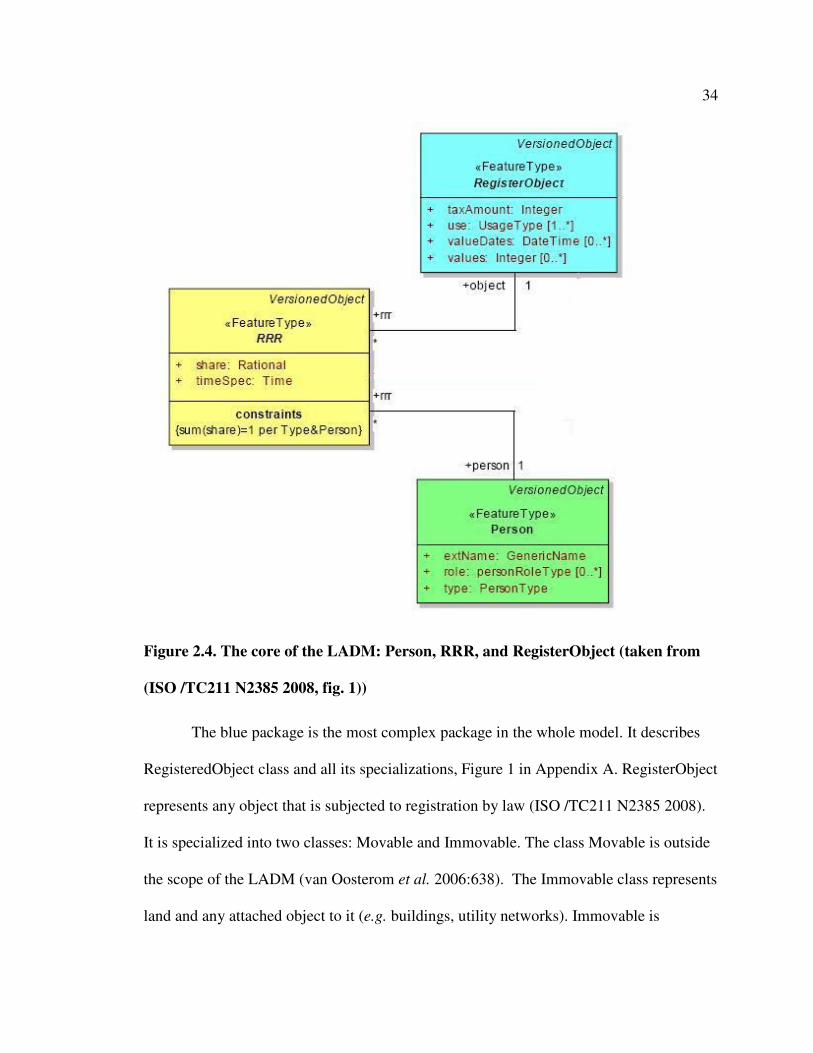
The heart of the LADM is represented by the main three classes: Person (e.g. an
individual, a group), RegisterObject (e.g. a parcel, a building) and RRR (Right,
Restriction, and Responsibility). Person and RegisterObject classes are not related
directly, but via RRR. Figure 2.4 shows the core component of the LADM in UML
diagram (Booch, Rumbaugh, and Jacobson 1999).
The LADM is modelled using UML class diagrams (Booch, Rumbaugh, and
Jacobson 1999), and it is organized into several UML packages. Each package presents
an independent aspect of a cadastral system and is indicated by a specific colour, namely:
1. Person aspects (the green package)
2. RegisterObject, Immovable class specializations (the blue package)
3. Legal/Administrative aspects (the yellow package)
4. Surveying aspects (the pink package)
5. Geometric/topological aspects (the purple package)
The green package represents the different types of persons who are involved in
land administration domain. It includes two classes: Person and GroupPerson, as shown
in Figure 1 in Appendix A. A Person can be of the type natural person or non-natural
person, such as a company or an organization. Also, a person has a designated role, such
as a money provider, a surveyor, or a conveyor. A GroupPerson is a specialization of
Person and it aims to represent communities, co-operatives and other social structures. A
GroupPerson is composed of two or more persons.
34
Figure 2.4. The core of the LADM: Person, RRR, and RegisterObject (taken from
(ISO /TC211 N2385 2008, fig. 1))
The blue package is the most complex package in the whole model. It describes
RegisteredObject class and all its specializations, Figure 1 in Appendix A. RegisterObject
represents any object that is subjected to registration by law (ISO /TC211 N2385 2008).
It is specialized into two classes: Movable and Immovable. The class Movable is outside
the scope of the LADM (van Oosterom et al. 2006:638). The Immovable class represents
land and any attached object to it (e.g. buildings, utility networks). Immovable is

35
classified into two categories: land (i.e. the ‘parcel’ family), and the ‘other objects’(ISO
/TC211 N2385 2008:5). Parcel, shown in Figure 2 in Appendix A, includes the following
classes: RegisterParcel (full topology), SpaghettiParcel (polygons with no topology),
PointParcel (single point), and TextParcel (only description, no geometry). The second
category of immovable includes: BuildingUnit (an apartment or a shared area in a
building), LegalSpaceBuilding (a collection of two or more building units),
OtherRegisterObject (an area of an easement), LegalNetwork (area around a utility
network), and NonGeoRealEstate (a RegisterObject that does not have a geometric
description yet). Each specialization of immovable can be associated with one or more
persons via RRR.
The abstract class RRR (Right, Restriction, and Responsibility) is the main class
in the legal\administrative package (the yellow package). This package is based on the
notion of “one strongest (primary) right, with other limited rights derived [or subtracted]
from it” (van Oosterom et al. 2006). RRR defines the relationship between a Person and a
RegisteredObject and hence is specialized into three classes: Right, Restriction, and
Responsibility. Within the context of LADM, Right represents the strongest interest that a
Person can have in a RegisterObject, e.g. ownership, freehold. Restriction, according to
the authors of the LADM, means “that you [the land holder] have to allow someone to do
something or that you have to refrain from doing something yourself [in the
RegisterObject which (s)he is holding].” (van Oosterom et al. 2006:648), such as
servitudes, zoning regulations and other planning restrictions. Responsibility means that
one has to do something actively, such as snow shovelling and lawn mowing (van
Oosterom et al. 2006). RRR is associated with LegalDocument class; in that, all rights,

36
restrictions and responsibilities originate from a legal document which represents the
source document.
The pink package models observations (survey points) and measurements taken
for immovable object specializations (in particular RegisterParcel, SpaghettiParcel,
PointParcel, LegalSpaceBuilding, and OtherRegisterObject). This package includes two
classes: SurveyPoint (representing observation points), and SurveyDocument (the source
document that provides spatial description of an immovable object, e.g. a survey plan or a
field sketch). A SurveyPoint is associated with a SurveyDocument as one
SurveyDocumnet can be the source of one or more SurveyPoints.
The purple package provides a geometrical and topological representation of
parcels and survey points in 2D and 3D, Figure 3 in Appendix A. The package is based
on ISO and OGC standards (OGC 1999; ISO 1999). A parcel has a spatial representation
attribute which can be composed of a collection of TP_Solids (3D volumes), TP_Faces
(2D polygons), TP_Edges (lines) and TP_Nodes (points). This package is outside the
scope of this research.
Although rights are intangible, they are modelled as a standalone class (RRR) in
the LADM, as portrayed in the figure above. This approach has several advantages, such
as:
1. It gives more emphasis to rights in the model (i.e. grants importance) by
explicitly modelling the rights with its own class, thereby accumulating all rights in one
class. So, if a system operator is looking for information about rights in land, (s)he knows
where to find them in the model.

37
2. It gives the ability to assign attributes to rights, such as type, textual
description, spatial description of the area of the right, and the time when the right is in
effect (start and end time).
3. A stand alone class (RRR) for rights can have specialization classes or
inherit from other classes, such as VersionedObject in LADM. Also, it has the ability to
have relationships with other classes, such as the relationship between RRR and
SourceDocument.
However, rights cannot exist independently. Other information is required to
define a right, such as who holds the right, and the immovable object to which the right
applies. Therefore, rights must be associated with at least one RegisteredObject and one
Person. This is translated in the LADM as shown in the UML notation in Figure 2.4 by
the compulsory association of RRR with Person and RegisterObject. The number ‘1’ at
the end of the association indicates that each right involves exactly one Person and one
RegisterObject. However, this posits a question of how real rights (i.e. rights in rem2) can
be modelled, where a RegisterObject, regardless of its owner, holds rights (e.g. a right of
way) in another adjacent (neighbouring) RegisterObject?
2 Rights in rem: rights which ‘run with the land’; in that, they remain valid even when the land is
transferred and the registered owner is changed (van Oosterom et al. 2006).

38
As mentioned earlier, the class RRR is specialized into Right, Restriction, and
Responsibility. The author questions the need of a separate class for Restriction, as
presented in the LADM (see Figure 1 in Appendix A). In the current thinking of LADM,
there must be at least one right instance, representing the primary (strongest) right, e.g.
ownership or leasehold, between a RegisterObject and a Person. A restriction is regarded
as any non-primary right held by a third party which can be added to or subtracted from
that primary right (ISO /TC211 N2385 2008; van Oosterom et al. 2006). In other words,
a restriction is seen as an additional right to someone’s primary right (positive-side) or as
a subtraction to someone else’s right (negative-side). Hence, a restriction, in essence, is a
right (that is in some way associated with another primary right). Therefore, restrictions
should be stored with other rights in the Right class.
This same conclusion is realized in the CCDM (the earlier version of LADM).
That is, restrictions (subtractions) are not stored in the model. Instead, they are modelled
as views that can be derived when needed (on demand), see Figure 2.5.

39
Figure 2.5. RRR specialization in CCMD. Restriction is a View (taken from (van
Oosterom et al. 2006, fig. 9))
This leads to the question: if restrictions are meant to be derived (implied), how
could this happen? One informed answer could be by applying a spatial overlay function
on a register object to determine which other RegisterObjects overlap with it. This is an
acceptable solution and it is indeed compliant with Cadastre 2014 principle of
independent layers (Kaufmann and Steudler 1998). However, it could be, in some cases,
impossible or inconvenient, such as in case of data availability in different reference
systems or in cases where no geometry of the RegisterObject (TextParcel) is available.
Therefore, the author suggests adding an explicit association from one right to another to
model the negative side (the subtraction) of the restriction, see Figure 2.6. Perhaps, the
main drawback of this approach is if a restriction is affecting many rights, e.g. a pipeline

40
passes through many privately owned parcels, the restriction information should be
related to every primary right (ownership) it encumbers.
Figure 2.6. RR class specializations
Although LADM addresses situations which are clearly different than those
addressed in this research, it is still relevant. The LADM is not designed to address
informal tenure and unstable situations; that is, it does not fulfil all the requirements
needed in customary and informal tenures (Lemmen et al. 2007; Augustinus 2005). The
LADM is more aligned to deal with and record registerable rights and formal land tenure
information (ISO /TC211 N2385 2008:22). Therefore, a specialization of the LADM was
designed. This model is called the Social Tenure Domain Model (STDM) and it is
described in the next section.
2.6.2 The Social Tenure Domain Model (STDM)
The first draft version of the STDM was developed and published in (Lemmen et al.
2007). It is based on a set of requirements presented by Augustinus et al. (2006) at the 5th

41
FIG Regional Conference in Accra, Ghana, in 2006. The requirements mainly mandate
developing legal and technical land tools that are pro-poor, i.e. tools that facilitate
delivery of tenure security for the poor.
The STDM pertains closely to the subject matter of this research. It aims to model
the person-land relationship regardless of its formal\legal status. More specifically,
STDM addresses situations similar to those addressed in this research, viz. post-conflict
situations, informal settlements, and customary areas. As stated in (Lemmen et al. 2007)
the social tenure domain model is developed “specifically for developing countries,
countries with very little cadastral coverage in urban and rural areas, for post conflict
areas, countries with large scale informal settlement and/or large scale customary areas.”
As mentioned earlier, the STDM is a specialization of the LADM. In fact, the
STDM is very strongly biased by the LADM to the degree that it uses almost the same
structure and classes provided by the LADM but with different terminology, e.g.
RegisterObject is called SpatialUnit and RRR is renamed SocialTenureRelation. It is
suggested by (ISO /TC211 N2385 2008) that “the LADM contains the functionality for
the STDM, but under incorrect terminology.” However, it is also stated in (ISO /TC211
N2385 2008:22; Lemmen et al. 2007:2) that “not all the requirements could in fact be
addressed by the LADM [\CCDM] and that additional domain requirements would still
need to be included.” So, the following rhetorical questions are crucial: Why develop the
STDM if it uses the same structure (design) as the LADM? And how does the STDM
address the additional requirements (stated in the second quote) while using the same
design as the LADM?
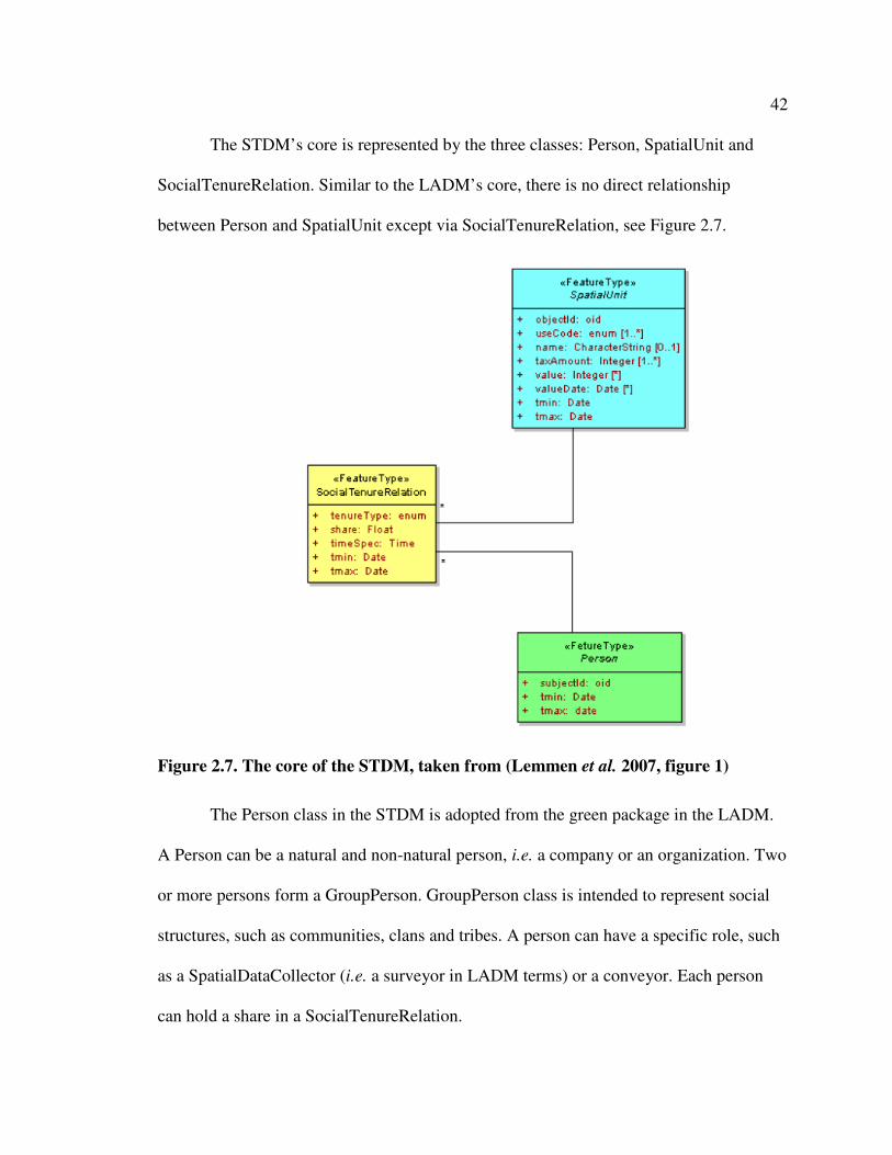
42
The STDM’s core is represented by the three classes: Person, SpatialUnit and
SocialTenureRelation. Similar to the LADM’s core, there is no direct relationship
between Person and SpatialUnit except via SocialTenureRelation, see Figure 2.7.
Figure 2.7. The core of the STDM, taken from (Lemmen et al. 2007, figure 1)
The Person class in the STDM is adopted from the green package in the LADM.
A Person can be a natural and non-natural person, i.e. a company or an organization. Two
or more persons form a GroupPerson. GroupPerson class is intended to represent social
structures, such as communities, clans and tribes. A person can have a specific role, such
as a SpatialDataCollector (i.e. a surveyor in LADM terms) or a conveyor. Each person
can hold a share in a SocialTenureRelation.
43
The SocialTenureRelation class in the STDM replaces the RRR (Right,
Restriction, and Responsibility) class in the LADM. This is necessary because the class
RRR and its specializations suggest a legal basis which is not always the case in social
tenure relations (Augustinus, Lemmen, and van Oosterom 2006:8). Social tenure
relations are merely interests and claims which are not necessarily legally enforced, but
they are recognized by a local social system (Lemmen et al. 2007). As shown in Figure 1
in Appendix B, SocialTenureRelation has a ‘type’ attribute which is used to define the
type of the social tenure relation. This attribute is linked to a lookup table that lists all the
possible tenure relations in a situation, such as ownership, informal type, customary type,
cooperative, etc, a list of tenure types is shown in Figure 1 in Appendix B at the lower
right corner.
The SpatialUnit class, as shown in Figure 2 in Appendix B, is categorized into
several groups:
• Parcel Family (including DescriptiveSpatialUnit, PointBasedSpatialUnit,
IncompleteSpatialUnit, and SketchPhotoSpatialUnit);
• Building family (including Building, IndividualUnit, and SharedUnit);
• and OtherSpatialUnits (including OverlappingSpatialUnit and
FishingRights).
The SpatialUnit class in the STDM re-uses the functionality of RegisterObject
class in the LADM. It allows flexibility in defining land objects (i.e. areas on which
social tenure relations, e.g. rights, are exercised). It allows the definition of land objects
using methods other than accurate surveys and geometrical measurements. SpatialUnits
can be defined by a point (PointBasedSpatialUnit), spaghetti polygons where there are

44
not topological structures and polygons are allowed to overlap and have gaps between
them (IncompleteSpatialUnit), textual description (DescriptiveSpatialUnit), and graphical
(pictorial) data (SketchPhotoSpatialUnit). Further, a SpatialUnit can represent an area
where there is no specific territory (the FishingRights class) and it can represent areas in
cases of conflict where SpatialUnits may overlap (OverlappingSpatialUnits), refer to
Figure 2 in Appendix B. A spatial unit is represented at most by one of the
aforementioned classes. Representing a spatial unit by two or more classes (e.g.
DescriptiveSpatialUnit in addition to SketchPhotoSpatialUnit) is not supported in this
design although it may lead to more comprehensive and complete representation of
spatial units.
In general, the STDM model assumes stability in the situations it addresses and
that these situations are fully understood. The SpatialUnit class exemplifies the latter. In
particular, the model strives to include all the possible specializations of a SpatialUnit
that may be encountered in a situation. However, it is not feasible that all possible types
of SpatialUnits can be known in advance; therefore, any instance of a new type of
SpatialUnit must fall under one of the specializations of the SpatialUnit class. In the
author’s opinion, the STDM should allow far more flexibility in the model to deal with
the uncertainty that characterizes the target situations. That is, it should leave room for
spatial units that outsiders (i.e. system designers and IT experts) do not or cannot know
about or understand, simply because they do not have access to information about them.
To illustrate, an example of this is found in North American aboriginals, where particular
stories are not allowed to be disclosed except to people of a certain social rank in the tribe
(Barry 2008e).

45
The above discussion highlights weaknesses as well as opportunities for an
alternative approach to develop data models that are more flexible and culturally
appropriate. This alternative approach is the focus of this thesis.
2.7 Chapter Summary
This chapter introduced the concepts of land administration, land tenure, and cadastral
systems as well as explained the relationship between these concepts. More specifically,
it showed that land tenure is a subsystem of land administration, and that cadastral
systems can be perceived as a tool to primarily serve the purpose of supporting land
tenure security by collecting and recording land tenure information.
The chapter also demonstrated that in order for cadastral systems to accommodate
the complexity and the wide array of different tenure types, they have to be sufficiently
flexible. Moreover, in case of uncertain situations, the system should accommodate the
uncertainty found in the tenure system in these situations.
Finally, the chapter presented two cadastral models, namely, the Land
Administration Domain Model (LADM) and the Social Tenure Domain Model (STDM).
These models were examined and evaluated. Generally, they assume that the
requirements for the situations they aim to address are rigorously and thoroughly
understood. They therefore tend to impose predefined detailed structures (designs) on the
situations. In fact, this underlines potential research for new model development which
utilizes more participatory and evolutionary approaches.

46
This chapter has addressed the secondary objective (a) stated in Section 1.5 which
is to investigate the characteristics of land tenure in uncertain situations. To achieve this
objective, the first research activity in Section 1.7 has been undertaken.

47
Chapter Three: Software Development Approaches
3.1 Introduction
This chapter augments Chapter 2 as it represents the second part of the literature review
conducted for this research. It investigates Software Engineering literature, aiming
primarily to identify a software development approach that is most suitable for
developing a land information software system for uncertain situations. To do that, a
review of some of the renowned approaches that can be adopted to achieve this goal is
presented. In particular, the author examines theories and practices in the Software
Engineering discipline which address software development for situations where
requirements are uncertain and a short system delivery time is needed. The chapter
partially addresses the primary objective of this research (see Section 1.5), and fulfils one
of the secondary objectives mentioned in Chapter 1, particularly the secondary objective
(b): To identify an appropriate software development approach which is suitable for
uncertain situations.
The chapter commences by describing the importance of software development
approaches. It then presents various development approaches, namely the waterfall
model, the spiral model, prototyping and the evolutionary model. Finally, the software
development approach adopted in this research is justified.
3.2 Software Development Approaches
A software development approach, also known as software process model, is a
framework that describes how the necessary software development activities are usually

48
organized (Budgen 2003). As Boehm (1988) pointed out, a process model addresses the
following software project questions:
1. What should be done next?
2. And for how long should it continue?
The first question indicates the order of the activities involved in software development.
And the second question establishes the transition criteria for progressing from one
activity to the next, defining the entrance and exit criteria for each activity (Boehm 1988).
Software development processes are proven significant as they can provide a
strong management framework for planning and controlling development, and hence they
contribute to the completion of software production on time and within budget. Further,
pursuing an inappropriate process model may lead to grief and failure of the software
project (Boehm 1988).
In this section, the author looks at various software development approaches.
These are the waterfall model, the spiral model, prototyping, and the evolutionary model.
The latter is preceded by a brief description of the iterative and incremental models which
form the basis of the evolutionary model. Each model will be presented in detail in the
following sub-sections.
3.2.1 The waterfall model
The waterfall model (Royce 1970) is described as a logical, stepwise process model in
which software development activities (requirements, design, coding and unit testing,
system integration, operation and maintenance) progress sequentially in a linear fashion
(Leffingwell and Widrig 2003; Budgen 2003). Figure 3.1 illustrates how the waterfall
model consists of successive software development activities where requirements precede

49
design, design precedes coding and implementation and so on. Figure 3.1 also shows the
feedback loops between successive stages acknowledging that design affects
requirements and that coding may sometime cause the design to be revisited (Leffingwell
and Widrig 2003; Boehm 1988).
The waterfall model represents a document-driven approach; that is, transition
from one phase to another depends on a fully elaborate document which marks the
completion of the current phase (Boehm 1988).
Figure 3.1. The waterfall model (after (Leffingwell and Widrig 2003))
The waterfall model has become widely used. It has overcome difficulties
encountered by the earlier two-phase “code-and-fix” model by adding dedicated
requirements and design phases to the model (Boehm 1988). This reinforced the role of
requirements and contributed to producing more well-structured software that can be

50
maintained and fixed at relatively low cost. Further, the simplicity of the waterfall model
and its linear structure makes it relatively easy to manage (Gordon and Gordon 1999).
Despite the aforementioned advantages, many problems of the waterfall model
are highlighted in the literature. Perhaps the most significant one is that requirements of
the eventual software product are identified once (right at the beginning of the
development process) (Budgen 2003). Also, as mentioned earlier, the waterfall model
emphasizes a fully elaborate document as a requirement to exit from each stage thus
acting as a potential barrier. Consequently, this led the waterfall model to become highly
inflexible. In particular, requirements are ‘frozen’ for the life of the project; in that,
development continues independent of changes occurring in requirements (Budgen
2003). Furthermore, using the waterfall model means that the system is delivered as a
whole; no component of the software will be delivered until near the end of the project
(Gordon and Gordon 1999).
To conclude, the waterfall model is most appropriate in stable domains where
system needs are well-identified and understood, they are not likely to change during the
lifetime of the project, and when system delivery time is not a critical factor in the
development process. Therefore, it is not suited to this research problem.
3.2.2 The spiral model
The spiral model is a risk-driven approach which means that the software development
activities are determined according to the result of risk evaluation processes. According
to (Boehm 1991) risk items that may affect the software development process include,
inter alia, personnel shortfalls, unrealistic schedules and budgets, developing the wrong

51
software functions, developing the wrong user-interface, and real-time performance
shortfalls.
Understanding of the spiral model paradigm varies among researchers. One
simplistic description of the spiral model, which regards it merely as a combination of
prototyping and the waterfall model, is pointed out by (Leffingwell and Widrig 2003:27)
as follows:
“In the spiral model, development is initially driven by a series
of risk-driven prototypes; then a structured waterfall-like
process is used to produce the final system.”
However, Boehm, in his pivotal study (1988), outlined the major activities that occur on
each cycle of the spiral, see Figure 3.2, as follows:
1. Objectives, alternatives, and constraints definition: In this phase, the
objectives of the cycle (e.g. achieving a particular functionality), the
alternative means to achieve them (e.g. design A, design B), and the
constraints imposed on application of the alternatives (e.g. schedule,
budget) are identified.
2. Risk Analysis: In this phase, the alternatives are evaluated against the
objectives and constraints. Also, this phase often identifies the areas of
uncertainty that are significant sources of project risks.
3. Development and verification: According to the results of the risk
analysis, a cost-effective strategy for resolving the sources of risk will be
adopted. This might involve development of prototypes, simulations, and

52
benchmarking. This phase also guides the development approach to be
used in the cycle, e.g. evolving prototypes, waterfall model.
4. Planning: A plan for the next cycle of development is created in this
phase.
Figure 3.2. The spiral model (taken from (Boehm 1988))
In light of Boehm’s discussion (Boehm 1988), the spiral model accommodates
any appropriate mixture of software development approaches, and this mixture is chosen
by considering the potential project risks. Therefore, the earlier explanation of
(Leffingwell and Widrig 2003:27) for the spiral model can be considered as a special case
(i.e. one scenario) driven by certain types of risks.

53
The spiral model might be most suitable for extremely large, complex projects
where there are diverse and dynamic risks threatening the development process. Indeed,
the explicit risk consideration is the principal feature of the spiral model. However, for
the purpose of this project, this is not an attractive feature as the project has explicitly
been designed to address particular risks, namely, uncertainty, changing requirements,
and rapid system delivery. As the risks have already been identified, the spiral model is
not required in the form expressed by Boehm (1988).
3.2.3 Prototyping
A prototype, in its simplest form, can be mock-ups of the layout or format of the
software’s user-interface (Budgen 2003). Also, a prototype can refer to a working
software item, given the fact that, as the name suggests, it is technically incomplete
(Budgen 2003). However, in this research, and for use in later chapters, the author adopts
Alavi’s definition of a prototype being: “an early version of a system that exhibits the
essential features of the later operational system” (Alavi 1984).
A software prototype serves different purposes. Generally, prototypes are used to
elicit and validate requirements; evaluate and test key aspects of a possible design; and
investigate execution tradeoffs and measure system performance. Based on the purposes
they serve, prototypes are categorized into two distinct groups (Davis 1992):
1. Throwaway prototypes: This type is built on a quick-and-dirty basis. It is
developed for experimental or exploratory reasons; that is, developers use
it to test some part of the system, or to clarify user requirements. After the
desired information is learned, the prototype is discarded.

54
2. Evolutionary prototypes: This type of prototype is built in a quality
manner. The prototype gradually evolves to form the final system through
implementing the requirements as they become clearer (Budgen 2003:51).
Generally, evolutionary prototypes are used when a working software is
needed very quickly and when system requirements are not known early in
advance.
Prototyping has appeared in information systems (IS) development literature since
the late 1970s (Beynon-Davies, Tudhope, and Mackay 1999); nevertheless, there is no
clear consensus about what prototyping really is. Definitions of prototyping practice vary
amongst researchers. Prototyping has been widely conceived as an alternative IS
development approach (Boehm 1976; Naumann and Jenkins 1982; Graham 1989; Vonk
1990). For instance, Vonk (1990) defines prototyping as being “an approach to building
information systems which uses prototypes.” In contrast, Floyd (1984) asserts that
prototyping is not, in itself, an approach for IS development, but rather it is considered as
a development activity\procedure combined with other approaches, as in the spiral model
(see Section 3.2.2). In essence, prototyping is a technique used to deal with uncertainties
(in user requirements and system behaviour) in information systems development
(Giddings 1984). According to (Bimson and Burris 1990), prototyping is a means for
exploring design alternatives through “an iterative design-code-test loop.” In this
research, the author adopts the concept of prototyping as a development activity within
other information systems development approaches.
The advantages of prototyping are widely acknowledged (Beynon-Davies,
Tudhope, and Mackay 1999). Prototyping is a good practice for coping with uncertain

55
requirements. This is supported by a survey conducted by (Hardgrave 1995) who found
that unclear requirements is the number one reason that pushes industries to use
prototypes. Using prototypes leads to significant improvements in requirements due to
the immediate feedback from users, as well as better user-developer communication
(Beynon-Davies, Tudhope, and Mackay 1999). Further, as mentioned earlier, prototyping
is a general development activity, and hence it can accommodate or be combined with
various system development approaches.
On the other hand, prototyping also has disadvantages. For example, the cost of
development effort increases (particularly in requirement analysis phase) when using
prototyping (Warren 1995). Also, project management becomes more difficult as
prototypes can be difficult to manage and control, especially in terms of budget and scope
(Alavi 1984; Beynon-Davies, Tudhope, and Mackay 1999).
3.2.4 Iterative, incremental and evolutionary development
Iterative development delivers the full system at once, and it keeps revising and refining
the existing functionality iteratively (Pfleeger 1998:56). Unlike the waterfall model, the
iterative approach allows developers to revisit (not sequentially) various activities, such
as requirements, design, and coding, during various iterations of the project (Leffingwell
and Widrig 2003). Ideally, iterations do not involve adding new functionality. In each
iteration, existing functionality is refined or changed (Pfleeger 1998).
Incremental development delivers the system in batches, in an incremental way
(i.e. adding new functionality) (Pfleeger 1998:55). The various parts (functions) of the

56
system are developed at different times, and integrated incrementally when they are
completed.
When the development process combines both approaches, incremental and
iterative, it becomes evolutionary (Ambler 2003:150). An evolutionary development
approach starts with an initial operational system which gradually evolves over time
(Boehm 1988:63). The initial operational system builds only the requirements that are
well-understood and progresses as modifications occur to requirements and\or other
requirements become clearer. The evolutionary approach works well when users do not
know what they want initially (i.e. uncertain user needs), but they can formulate an idea
about them when they see them implemented in a working system (Boehm 1988).
In evolutionary development, the system is changing on an on-going basis. There
is no notion of a ‘final product’, but rather the notion of ‘current state’ of the system
(Budgen 2003; Beynon-Davies, Tudhope, and Mackay 1999).
The advantages of the evolutionary approach are attained from the strengths of the
incremental and iterative approaches. For example, delivery time for the first operational
system is short as the system emerges and is delivered rapidly to users (first iteration, first
increment). Also, the evolutionary approach does not have distinct phases for carrying
out the development activities, e.g. requirement, design and coding phases etc. Rather, all
these activities\tasks take place as needed iteratively throughout the life time of the
project (Ambler 2003:152). As a result, the developed software becomes highly resilient
to change (i.e. has better adaptability to change). As McCracken and Jackson (1982) put
it: “The life cycle concept rigidifies thinking, and thus serves as poorly as possible the
demand that systems be responsive to change.”

57
The evolutionary approach also has its weaknesses. For example, it is usually
based on the assumption that the initial, operational system will be flexible enough to
accommodate all the possible evolution paths (Boehm 1988). This is particularly
unrealistic in case of unplanned evolution where the system may require major
restructuring in order to continue to evolve (Davis, Bersoff, and Comer 1988).
3.3 The Adopted Approach
The previous section discussed several software development approaches. Each of these
has its own strengths and weaknesses. However, for this research project, the author opts
for the evolutionary approach to be used as a basis for the methodology developed in this
research project (see Chapter 4). He also utilizes prototypes (in particular evolutionary
prototypes) as a means for data collection and requirements elicitation during the life
time of the project.
This selection was made primarily because the nature of the evolutionary
approach is most suitable for uncertain situations, where requirements are ill-defined, and
the system is expected to change continuously. In effect, the flexibility of the
evolutionary approach, which allows software development activities to be undertaken
iteratively as needed, qualifies it to be used in such situations. Moreover, the advantages
of the evolutionary approach, presented earlier, namely: ability to deal with uncertain
requirements, willingness\acceptance to change, and short delivery time, are found
attractive as they match what is needed for developing LIS software in uncertain
situations.

58
3.4 Chapter Summary
This chapter presented various software development approaches. It started with the
waterfall model where software is developed by undertaking sequential steps progressing
from requirements elicitation, design, coding and testing. This is followed by a
description of the spiral model in which project risks derive and guide the software
development process. After that, prototyping as a software development technique was
described. Afterwards, the evolutionary approach was discusses as a flexible approach for
software development which combines both iterative and incremental methods. This
chapter is important as it describes and argues the evolutionary approach which will be
used in Chapter 4 as a basis for the methodology developed in this research project.
As per secondary objective (b) in Section 1.5: to identify an appropriate software
development approach that is suitable for uncertain situations, the evolutionary approach
is adopted. Research activities 1 and 3 in Section 1.7 have been undertaken to achieve
this secondary objective.

59
Chapter Four: A Methodology for LIS Software Development in Uncertain
Situations
4.1 Introduction
This chapter presents the major contribution of this research; a methodology which can
be used specifically for developing land information system (LIS) software in uncertain
circumstances. This was accomplished by fulfilling the primary objective of this research
(see Section 1.5). To achieve the primary objective, it was necessary to develop a flexible
and evolving cadastral data model that suits uncertain situations as per the secondary
objective (c) in Section 1.5, which is also presented here.
To re-cap on what has been presented in previous chapters, this research
addresses unusual circumstances characterized by uncertainty, such as post-conflict
situations, informal settlements, and customary tenure areas (Section 2.5). Current
initiatives trying to address these situations such as the Social Tenure Domain Model
(STDM), presume ample understanding of such situations which leads to mechanistic
solutions (Section 2.6.2). However, it is suggested that this is inappropriate as these
situations are very complex, dynamic, and diverse (Section 1.4). For this reason it is
impossible to have a complete understanding of all aspects of these situations, including
tenure, in advance. Thus, it is not feasible to model land tenure information (via a set of
classes and relationships) correctly a priori.
However, although these situations are uncertain, and at times chaotic, there is
still great value in collecting tenure information as quickly as possible. In the long term,
this information, augmented by new data, can be used to support restitution claims,

60
unravel wrongful land allocations, and form the basis of a well-designed LIS in the
future. Hence, LIS software should accommodate uncertainty. In particular, it should
adapt to the changing conditions, and be flexible enough to collect, store and relate tenure
information in a manner which makes it useful in the future when the uncertainty
unravels (Muhsen and Barry 2008).
The author has therefore applied an evolutionary approach (Sections 3.2.4 and
3.3) to design a LIS software development methodology. The methodology could be
employed by local level registration offices, land administration authorities or NGOs
collecting data on land tenure and who have an interest in securing land tenure.
The following section describes the methodology in further detail.
4.2 The Methodology
The methodology uses concepts from the evolutionary approach, such as reliance on user
feedback, heavy use of working systems and prototypes instead of elaborate documents,
and iterative and incremental development.
The methodology proposes a flexible, initial system, called “System 0,”
comprised of a model and a software prototype as a starting point for LIS development,
see Figure 4.1.
This initial system is used for data collection and requirement elicitation. It
evolves gradually over time to suit the current situation and meet the latest requirements.

61
Figure 4.1. High-level view of LIS software methodology
As shown in Figure 4.1, the methodology uses an iterative process. However, the
initial system is not part of the development iterations. The initial system provides the
starting point from which the methodology begins. At the first iteration, the initial system
(“System 0”) becomes the current system used primarily for data collection. The current
system is analysed (Analyse system step in Figure 4.1) on an on-going basis while
considering several factors and conditions, such as the level of stability in the situation in
which the software is being implemented, users’ feedback and consensus over new
requirements of the system. This step may result in a number of change requests that
highlight potential enhancements of the current system. Accordingly, the system evolves
to apply these enhancements resulting in a new release of the system (evolved system).
Then, a data migration process concludes the development iteration where data from the
old system is migrated to the evolved one. Finally, the evolved system starts a new
iteration.
These aforementioned steps are discussed in further detail in the next subsections.

62
4.2.1 The initial system
As part of this research, the author developed a simple, yet flexible, initial system. It is
envisaged that this initial system (‘System 0’ in Figure 4.1) addresses the immediate
situation after a conflict such as a civil war, where the situation is still unstable, chaotic
and uncertain. Thus, the primary purpose of this initial working system is to collect data
at a fast pace, i.e. quick and dirty, allowing different data types to be collected within a
loose structure. In later iterations, as will be shown in Section 4.2.3, the system may
evolve and serve different or expanded purposes.
The initial system represents the first release of an evolutionary prototype (see
Sections 3.2.3 and 3.3). It implements basic and clear requirements only. These include
the fundamental classes of a land information system (such as Person, Land) and database
operations (e.g. add, delete, and modify records). The implementation of the initial
system is described in Section 5.2.
Also, the initial system incorporates multimedia data to augment conventional
written documents, survey plans, and other forms of maps and imagery. In fact, this study
builds on a previous research conducted by Barry (Barry 2008d; Barry and Khan 2005;
Barry 2006a; Barry et al. 2002) which affirms the usefulness of using multimedia data in
land information systems.
The initial system is composed of two main components, the initial model and the
initial software prototype. The following sub-sections elaborate on each component.

63
4.2.1.1 The initial design: the three-class model
The initial design consists of three general abstract classes, namely Person, Land
Object and Media, see Figure 4.2.
Figure 4.2. High-level conceptual view of the three-class model.
The Person class includes anyone who might be an interest holder in land and/or
involved in administering it (e.g. a land surveyor, system operator). It includes juristic
and non-juristic persons, e.g. companies and trusts. The Person class can also represent
social structures and lineage groups via recursive relationships which enable modelling
parent–child relationships, inheritance, and other interpersonal relationships.
The Land Object class may represent things such as parcels, volumes of space,
dwellings, trees, trap lines, religious artefacts, water bodies, and\or any geographic thing
of economic or cultural value (Muhsen and Barry 2008). Recursive relationships on Land
Objects allow situations within and between objects to be modelled. For example, a
64
dwelling is located on a parcel lot, or a piece of land may be subdivided into several
smaller parcels or created from a consolidation of several parcels lots.
Anything else, i.e. an object that is neither a person nor a land object, is deemed a
media item. The Media class contains a mix of records that might represent different
items of evidence relating to individual rights and interests (e.g. titles, deeds, and survey
plans describing parcel lots, marriage certificates, and rent cards), and contextual
evidence (multi-media recordings of dances, stories, and personal testimonies). Media
items comprise digital files such as video clips, digital photographs, oral recordings, word
processor documents and scanned documents of physical artefacts such as maps, survey
plans or written documents. The recursive relationship for the Media class applies when a
media item relates to another media item, e.g. a new survey plan supersedes a cancelled
survey plan.
Media items are incorporated in the model as an independent, separate class rather
than an additional field appended to all other classes (Muhsen and Barry 2008). There are
two primary reasons for this: (1) an independent class for media items allows the
inclusion of attributes describing the media files themselves, such as date captured or
issued, duration, and size; and (2) it enables many-to-many relationships with other
classes; many persons can have many media files related to them, e.g. many people may
appear in many videos.
The Media class is connected to the other classes (Person and Land Object) via
binary relationships: Person–Media and Land–Media. The Person–Media relationship
models cases such as a person appearing in a video clip, or a person who is the primary
landholder as shown in a deed. The Land–Media relationship includes cases such as when

65
a survey plan describes a parcel lot. It becomes very complex when one tries to include
within the data model everything captured in media items that may be relevant to the
situation at hand and how they relate with other classes (Muhsen and Barry 2008). In
fact, this is an advantage of using multimedia; it captures information that cannot be
modelled easily. For example, one cannot include in the model all relationships of all
persons or relevant land objects that appear in a video clip.
The Person class is connected to Land Object via the binary relationship: Person–
Land relationship. This relationship represents the set of interests or claims a person
might have in a land object, e.g. a hope of inheritance. Indeed, the author takes a different
approach to that used in the LADM for modelling the interests and rights that a person
might have in a land object.
In the LADM (see Section 2.6), rights are represented by an independent class
that connects the two other classes, Person and RegisteredObject. These right instances
originate from legal documents (instances of LegalDocument class, e.g. a title or a deed)
that give effect to these rights, see Figure 1 in Appendix A.
In the three-class model, however, the concept of a right is slightly different. A
right, or any other form of interest, is a relation between the person and the land object.
The author models it as a direct relation between the person and the land (Person–Land)
in case of lost or absent instruments (i.e. evidentiary files) or as an indirect relation via
the Media class which represents the evidentiary object (of which a legal instrument may
be an instance) that binds and describes the relation between the person and the land
object. Therefore, when the model is used, the concern is to collect relationships that
define interests in land; these interests can include legal rights, perceived rights, and even

66
conflicting claims and hopes. There is no need to create rights (and define their types) at
this stage, rather only record potential interests. Rights can be inferred from the evidence
and relationships in later stages, perhaps when an adjudication process takes place.
The three-class model is designed to meet two vital requirements: simplicity and
flexibility. As it will be shown later, these requirements influence decisions pertaining to
the model design. The author will discuss later in this subsection how these requirements
are fulfilled.
Simplicity is needed to match the locally available skills of people who are
expected to operate the model, given that skilled IT personnel are likely to be scarce in
the target situations (Muhsen and Barry 2008; Barry 2006b). Also, simplicity impacts
usability; that is, when the model is perceived as simple, it is more likely to be used by
operators. By definition, there are two attributes of simplicity. Firstly, there should be as
few classes (entities) as possible in the model. Secondly, the number of relationships and
the degree of these relationships (number of classes participating in a relationship, e.g.
binary, ternary) should be low (Muhsen and Barry 2008). Thus, to achieve simplicity, the
initial design is limited to the minimum number of classes (the three classes described
above), and it uses three simple binary relationships instead of one complex ternary
relationship. Using binary relationships also contributes to model flexibility.
To cope with the nature of the evolutionary development, the architecture of the
initial design must be resilient to extensive change. In that sense, model flexibility is of
major importance. Moreover, flexibility is required to cater for the uncertainty that
characterizes the situations where the model is expected to operate. Flexibility allows an
operator to record, store and retrieve information where user needs are vague, and the

67
exact nature of all the different relationships between classes and data items may not be
known (Muhsen and Barry 2008). By definition, flexibility means that a model is able to
support the different data types of records and to model the different scenarios\cases that
might be encountered in a situation.
Several factors contribute to the flexibility of the initial model. Firstly, the model
includes only generalized abstract classes. Each class contains fundamental fields only
(i.e. the common fields between different types of records). Further, each class has a
'Type' attribute which is linked to a lookup table that can be accessed and customized by
the user, see Figure 4.3. Using lookup tables in the model design significantly improves
its flexibility. Users have access to lookup tables which define data types in the system
(e.g. LandObjectTypes and MediaTypes). This enables them to define new types, modify
or remove already existing ones. Furthermore, a textual description field is provided for
each class to allow users to flexibly describe records in a free form of text, see Figure 4.3.
These description fields are proven useful, especially when fields within a class are
required but have not been defined\included in the current design yet. Then, values of
these missing fields are included under the description field as bullets of text.
Secondly, the relationships between the classes are designed to be sufficiently
flexible. Specifically, ternary relationships are avoided. Using a ternary relationship to
connect the three classes requires an instance of each of the three classes to be available.
This indeed rigidifies the model and this is not always convenient\applicable. Therefore,
in the three-class model, each class is related to each and every class in the design,
including itself, via binary relationships. Additionally, all relationships are of the type
many-to-many. This approach enhances the flexibility of the model and hence allows it to

68
represent most relationships in reality. Furthermore, each relationship has a textual
description field that enables the users to describe\explain a relation between two records
comprehensively in a free form.
Figure 4.3. Generalized classes with example of possible types.
Thirdly, having the Media class as an integral part of the model design manifestly
contributes to flexibility. Multimedia data can capture and model what is perceived to be
extremely complex to model (Muhsen and Barry 2008). Essentially, the Media class is
regarded as a container of a diverse set of records which each serves a different purpose
(a title, survey plan, image of a person, rental card). Each record has a description field to
allow the user to describe it freely. Also, each record in the Media class has a number of
user-defined attributes, called auxiliary attributes, see Figure 4.4. The user can create and
add an unlimited number of varying auxiliary attributes to each media item (i.e. record).
Therefore, records in the Media class share the fundamental attributes (the basic fields
that constitute the media table), but they may have different auxiliary attributes according
to the user. Auxiliary attributes are crucial in design refinement phases. In particular,

69
media items which share the same auxiliary attributes can be classified and migrated to
an independent, specialized class.
Figure 4.4. Media Auxiliary Attributes
Based on this initial model, an initial software prototype is developed. The
following subsection describes the second component of the initial system (i.e. the initial
prototype) in further detail.
4.2.1.2 An initial prototype for data collection
A software tool with a user-friendly interface (i.e. prototype) is developed to allow
system operators to populate the three-class model with land tenure and other related
data. This prototype is an evolutionary prototype (see Section 3.2.3). This implies that the
initial prototype gradually evolves to form the final system.
As mentioned earlier, the primary purpose which the initial prototype serves is
data collection. The significance of this data collection step emanates from the principle
that the more land tenure information is collected, regardless of its format and type, the
more likely security of tenure can be delivered\achieved in the future. In other words, the
information collected now contributes to security of tenure later in time. Thus, the system
strives to provide users with a flexible data structure and software that can support as the

70
collection and storage of as much tenure information as possible, perhaps not in the most
efficient way, hoping that, in the long term, this information will be useful for future use
(e.g. in land formalization\regularization). Also, the prototype can be used for
requirement elicitation; that is, collected data may inform new and\or clarify existing user
requirements and guide the refinement of the model and the software in future
development iterations (see Section 4.2.3).
Ideally, the prototype should be used to collect information about people, land,
social relations, and other land tenure information on the ground without intervening.
Hence, it is not the aim of the software to create new rights. On the contrary, it aims to
collect the available media items (i.e. evidence) that affirm existing relationships and
interests in land, and link them together.
The prototype can link a variety of data types such as conventional titles/deeds,
survey plans, reports, maps and similar analogue or digital documents, digital audio files,
photographs and video clips. The manner in which data are linked and queried allows a
great deal of flexibility to cater for uncertainties in a situation and unforeseen social
relationships.
Eventually, the prototype can be considered as a “library of evidence” (Kingwill
2008). It becomes of a significant value where it can be consulted to support future
applications and projects. For example, it can support restitution claims; assist in dispute
resolution, unravelling wrongful land allocation, land formalization and regularization. In
addition, the prototype and the information collected can lay the basis for reform projects
in the future.

71
4.2.2 System analysis
This step may provide the trigger that initiates the system evolution. The outcomes of the
analysis inform what changes should be applied to the model and the software prototype
in the following step. For instance, if a new purpose of the system is identified, a new
class should be added to serve that particular purpose.
This step involves examining several factors to determine if there are potential
enhancements for the system. Depending on these factors, the system analysis phase
initiates a change request in which the required changes to the system are declared.
These factors, as shown in Figure 4.1, may include consensus over new
requirements, identification of a new purpose of the system, feedback from operators in
addition to external constraints such as level of stability of the situations, politics,
institutions and governments, and availability of technical and human resources.
Also, the system analysis step entails analysing the data collected using the initial
prototype system. The collected data is used to gain insights about the tenure system
practiced on the ground and learn more about how it can be modelled appropriately.
These insights can clarify existing or drive new requirements that can be implemented
and hence enhance the system. In other words, after analysing the collected data,
presumably, new requirements will emerge and already existing requirements will
perhaps become clearer. Accordingly, the system is refined to reflect and accommodate
all the requirements.
Analysing the collected data involves probing or examining the content of key
fields and tables in the model. For instance, one can analyse the content of the description
field within a class and conclude that a new attribute is needed (if this attribute is

72
common in the textual description for most of the records). Likewise, the description
fields of the relationships. Their content can be very useful to learn more about existing
relationships and to investigate introducing new specific, concrete relationships between
classes if appropriate. Also, lookup tables may play a vital role in identifying types of
records used for each class. Perhaps, based on the available types, new sub-classes can be
introduced as specializations of the original abstract super-class, each with specific
attributes and relationships as appropriate. In addition, the Media class together with its
auxiliary attributes may lead to potential refinement; that is, media items which share the
same auxiliary attributes can be grouped together and transferred to an independent,
specialized class.
In brief, this analysis can identify necessary changes which trigger the system
evolution stage. System evolution is described in the next subsection.
4.2.3 System evolution
The system evolution phase is the step where change requests issued in the previous step
(system analysis) are actually applied. This step produces an evolved system that meets
latest user requirements and is most suitable to the current situation.
In a broad sense, system evolution can be described as adjusting (increasing or
decreasing) the level of flexibility of the system depending on the level of uncertainty in
the situation and how well user needs are understood. It is assumed that the more
uncertainty in the situation the system is meant to serve, the more flexible it should be.
Therefore, since the initial system (see Section 4.2.1) is meant to address the immediate
situation after a conflict such as a civil war or a natural disaster such as a tsunami(i.e.

73
high uncertainty), it represents the most flexible design for collecting various land tenure
information (as they appear, with no clear purpose in mind). However, when the
uncertainty in the situation diminishes; that is, consensus over user needs of the system is
progressively reached, and a new purpose of the system is identified, the flexibility of the
system should be reduced. This can be done by adding new classes, or by decomposing
the generalized classes into more specialized ones. Similarly, if the uncertainty in the
situation increases (instability occurs again), the system should revert back to a more
flexible, general design where subclasses are merged together and synthesised in
generalized classes (Muhsen and Barry 2008).
To illustrate the above, a simple example is given as follow: in the immediate
aftermath of a conflict such as a civil war, or a natural disaster such as a tsunami, land
institutions and records are destroyed, the situation is chaotic, and there is no consensus
over user needs. A team has been told to use the initial system (“System 0”) to collect all
the information relating to land parcels and other important land objects. All the
remaining data are collected: cadastral maps, survey diagrams, survey records, valuation
records, and deeds. Once the situation is understood, or aspects of it are understood, and a
potential purpose of the system has been identified, such as a filing system for titling,
then a fourth class, called Reference Instrument, is added to the system to serve that
particular purpose (Figure 4.5). Moreover, all the records in the Media class which serve
the purpose of titling (such as titles or deeds) are extracted and transferred to the
Reference Instrument class (data migration, see Section 4.2.4). Further, as Reference
Instrument records tend to have a specific purpose, special functions are applied to these

74
records that improve the integrity of the system, e.g. security functions and closing a
record to editing (Muhsen and Barry 2008).
A Reference Instrument can be related with other classes via the many-to-many
relationships between them (Ref–Person; Ref–Land; Ref–Media). Also, the Reference
Instrument class has a recursive many-to-many relationship in order to model situations,
such as a deed superseding another deed.
Figure 4.5. The 4-class model.
A second iteration of system evolution can occur, if, for instance, the purpose of
the system has changed again. In such scenarios, the Reference Instrument class may be
specialized into more sub-classes as it includes media items that serve varying purposes.

75
In the earlier example, say the system purpose is modified to include valuation
records. So, valuation records are then moved from the Media class to the Reference
Instrument class. Deeds and Valuation Records can be considered as subclasses of the
Reference Instrument class, see Figure 4.6.
Similarly, the opposite can take place if the situation deteriorates due to
increasing instability (because instability occurs again). The system might revert back to
three classes, where teams work in data-collection mode again without clearly identified
users or well defined user requirements. So, in the earlier example, if civil war broke out
again, then the system could revert to the more flexible system, the initial system (System
0) to serve the purpose of data-collection again.
Figure 4.6. Specializations of Reference Instrument class.
In short, the model evolution step suggests that the initial system should be
“scaled up” from three classes to four, and possibly more, as reasonable levels of
76
consensus over user requirements are accomplished. Over time, subclasses of Reference
Instrument, and indeed Person and Land Object, might be specified to reduce the
flexibility of the general classes. Or, it can be “scaled down” to three general classes to
increase the flexibility of the system to allow it to work in the data collection mode again.
4.2.4 Data migration
This is the last step of one cycle of the methodology. It aims to move the data from the
old design to the evolved one. In principle, the migration process involves three main
tasks, namely: data extraction from the old model; transformation of data to suit the
format and requirements needed for the new model, and data loading in which data is
imported to the new model. Also, a data verification process may be required at the end
of the migration as errors may have occurred (Kimball and Caserta 2004).
In the context of this study, data migration is case-specific. It can be done
manually or by using automated procedures. It also varies in its simplicity and cost, based
on the amount of refinement and differences between the old and the new models.
However, in concept, when generalizing classes, it should be possible to merge
the subclasses into a single table in the parent class without too many major implications.
But, the opposite process of decomposing classes into subclasses may not be as simple. In
the first case (generalization of classes), attributes’ values of the subclass are merged
together and appended as text in the description field of the parent class. In the second
case (specialization of classes in which data is migrated from the parent class to the
subclasses), extracting attribute values from the raw text of the description field and

77
mapping it to the corresponding attribute in the sub-class is difficult and requires effort
and time to do.
The completion of the data migration step marks the end of one cycle of LIS
development. The evolved system becomes the starting point for another development
cycle where system analysis and evolution are repeated indefinitely.
4.3 Chapter Summary
This chapter described a methodology designed by the author to develop land information
system (LIS) software in uncertain situations. The methodology is based on an
evolutionary approach. In particular, the development begins with a flexible operational
system (cadastral model and software) used for data collection and requirement
elicitation. This system is made to be flexible to cope with the uncertainty in the
situations it addresses. As requirements become clearer and the level of uncertainty
decreases (after analysing the collected data), the system is evolved to a refined version.
Finally, the collected data is migrated into the refined system. System analysis, system
evolution and data migration will continue for as long as necessary, that is while
requirements and uncertainty in the situation continue to change.
This chapter has addressed the primary objective of this research (Section 1.5)
which is to contribute to the development of an appropriate methodology for developing
LIS software for uncertain situations. It also fulfils the secondary objective (c) in Section
1.5 which attempts to develop a flexible and an evolving cadastral data model that suits
uncertain situations. To do this, research activities 2, 3, 4 and 5 in Section 1.7 were
carried out.

78
Chapter Five: Software Implementation and Testing
5.1 Introduction
This chapter describes the implementation and testing of the initial system developed in
Chapter 4. Further, it discusses the attempts made to test the methodology developed in
this research.
This chapter does not set out to test and evaluate the software and its underlying
methodology thoroughly. It provides an indication of their adequacy and potential use.
The testing and evaluation issues are considered as part of future research (see Section
6.3).
The implementation of the initial software is described in the following section.
Thereafter, explanations of the testing process of the software and the methodology are
presented.
5.2 Software Implementation
This section describes the technical realization of the software developed in this research,
the Object Manager (OM). The main motive for developing the OM software was in part
to develop and in part to test the methodology proposed in Chapter 4. In particular, the
OM is a proof of concept. It is implemented to demonstrate the viability of the primary
principle of the proposed methodology; that is, a simple, general cadastral data model
which incorporates multimedia can evolve over time into a more complex, specialized
model if the situation permits and vice versa. In that sense, the Object Manager is the

79
actual implementation of the initial system described in Section 4.2.1 which is designed
to evolve over time according to changes in the situation and the requirements.
The Object Manager is a Windows based desktop application that is designed as a
data management system to handle data stored in the computer as digital files, in database
tables and analogue sources such as written documents, maps, diagrams, video tapes,
DVDs and CDs. In this form, the OM is a good solution for a small survey practice, a
local level registration office or an NGO collecting data on land tenure.
Flexibility is a major requirement of the OM design as it allows tenure data to be
collected, managed, stored, linked, and described in many different ways. The
assumption is that flexibility gives the users an opportunity to use the software in a way
that they find suitable for their purpose and circumstances. This should ensure fewer
possibilities for the software to fall over.
The OM software consists of two components, namely the database and the user-
interface. Each component is described in the following sub-sections.
5.2.1 The database
The back-end database of the OM software is implemented in and managed by Microsoft
Access. MS Access is easy to use, straightforward to install, deploy, and administer.
Thus, it could be appropriate for local, community-level use where the data volumes are
expected to be moderate and computer skills limited. However, since MS Access, is not
able to store large multimedia data in the database, the database is designed to store a
pointer (i.e. file path or location) to the media files, not the files themselves. At this stage
of development, enterprise database management systems (DBMS) with true client–

80
server architecture and robust concurrency control are not required. If the system grows
to serve multiple users simultaneously and the data models become more complex, more
rigorous database engines should be used. Freeware databases, such as MySQL, may be
considered for this purpose (Muhsen and Barry 2008).
The initial design of the database is presented in the physical model depicted in
Figure 5.1. The physical model is a DBMS-dependent model that shows the internal
schema of a database design (Lightstone, Teorey, and Nadeau 2007). It shows the actual
implementation of the conceptual model in a specific database-management system. It
depicts the SQL data tables, the columns contained in them, in addition to their data
types, and the relationships between the tables.
The physical model presented in Figure 5.1 is a transformation of the conceptual
model of the initial data model depicted in Figure 4.2. It appears that the physical model
is significantly more complex than the conceptual model because the numerous many-to-
many relationships require a number of intermediate physical tables in the DBMS.
Moreover, look-up tables are added to the design to enable the users to define types of the
three general main classes of Person, Land Object, and Media. Also, the table
“tblMediaAuxiliary” is added to the design to handle the user-defined attributes of Media
class.

81
Figure 5.1. The OM Physical Model.
As a naming convention followed in creating the physical model, the main tables
start with the prefix “tbl,” the intermediate tables start with “rel” and the look-up tables
start with “lut.” Also, the notation used in the model shows the tables’ primary keys as
underlined, and required fields (that do not accept null values) are in bold print.
5.2.2 The software user-interface
The software front-end is a user-friendly environment that allows the user to populate the
physical model with data. The user-interface is developed using Microsoft Visual Basic

82
.NET (VB .NET). Visual Basic is very useful for producing graphical user-interface
(GUI) applications quickly.
The software user interface, depicted in Figure 5.2, is divided horizontally via two
main horizontal panels, viz. the upper and the lower panels. The upper panel contains tabs
that show records of each class. The lower panel shows the relationships of the selected
record in the upper panel with records from other classes.
Figure 5.2. The OM User-interface.
The functionality offered by the software is varied. It includes adding, modifying,
and deleting records. The system can play or show media items as well as provide record
search functions and procedures for linking and describing records. It also implements
security functions, which keep track of the last modification of a record. Also, the system

83
aims to address the key non-functional requirements, namely flexibility, usability and
ease of use. The reader is advised to refer to Appendix C: System Requirements
Document for a complete list and description of the software functional and non-
functional requirements.
5.3 Testing
This section is divided into two main subsections: testing the implemented initial system
(the OM), and testing the methodology. The former subsection focuses on testing the
technical functionality of the OM software, while, the latter explains the steps taken so
far for testing the methodology.
5.3.1 Testing the OM software
In the context of this section, software testing means to ensure that the functions provided
by the software meet their requirements (validation) and they are actually working
properly (verification). In this section, the focus is to address two primary questions:
a) Does the OM software meet its requirements?
b) What are the problems and limitations associated with the OM
software?
In this context, four means were used to address these questions:
1. In-house testing: performed by the author in addition to other members of the
Land Tenure and Cadastral Systems group at the University of Calgary using

84
fabricated data. Each function has been tested individually (unit testing) during
the development of the software, followed by an overall system testing at the end.
2. Testing via developing the OM tutorial: the software has been tested via
developing a tutorial which simulates various scenarios. The tutorial has been
used to train potential users on operating and managing the system in Nigeria. It
involves entering data of a family in a single house based on a pseudo-customary
system, where land is not registered and land rights are unrecorded. Family
relationships (e.g. parent–child, expected inheritance) are recorded using videos,
audio files, photographs and data from a census type survey. The process then
moves on to formalizing the tenure system through survey and registration, the
subdivision of land, consolidation of land, transferring of land as a consequence
of inheritance and claims arising out of an oral agreement to use the house as
collateral for a loan. The tutorial is included as Appendix D.
3. Testing by actual use: in February 2008, the software was licensed to and
deployed at the Directorate of Land Regularization in Lagos, Nigeria. Feedback
from users was obtained through periodical visits by the author’s advisor, Prof.
Michael Barry (Barry 2006a; Barry 2008b; Barry 2007). This has significantly
contributed to testing and detecting software limitations and problems.
4. Testing by demonstration: the software has been demonstrated to several key
experts in the cadastral domain. Feedback obtained from those experts contributed
to results of the software testing.

85
The results of the tests above established that the system meets its requirements
and it functions correctly. However, it also pinpointed major limitations and problems of
the software, as described below:
Difficulties associated with system flexibility: although the flexibility of the initial
system embodies positive attributes, there are a number of risks associated with this. On
the one hand, flexibility allows data to be collected in spite of its type and format. It also
allows tenure data to be stored, managed, linked, and described in many different ways,
as well as encourages users to think creatively about their land information system
design, and explore alternatives in collecting and relating tenure data. But, on the other
hand, if not used logically, flexibility may result in spaghetti; a meaningless set of
records. This assigns a huge responsibility to the system operators to define and adhere to
rules and procedures prior to working with the system. It also underlines the significant
amount of intuition and skill required from them. Careful design of the various data items
(i.e. records) and how these are to be described and their relationships with other records
is imperative. If users do not plan carefully, they may end up with a dysfunctional set of
records which are not particularly useful. To overcome this, training should be given to
users, and they need to adhere to well defined protocols and strict procedures on how to
use the system.
Further, flexibility may complicate data searching functions. In particular,
querying and searching data becomes difficult when records and relationships are
described in free text within the descriptive fields.
Difficulties associated with using Microsoft-based software: using Visual
Basic.Net and MS Access to implement the initial system was a point of criticism. As the

86
software is meant to address primarily communities in developing countries (poor
communities in general), it is suggested that using free, open source software would be
more suitable.
In addition, the storage capacity of the software is limited by the capacity of MS
Access file size, which cannot exceed the 2 gigabytes limit. However, this is still
acceptable as long as the system is intended for local-level, community use.
The user-interface: in general, the OM software was received enthusiastically by
all the people who viewed it (Barry 2007; Barry 2008a). However, its user-interface
requires more improvement. Although it was made to be intuitive to regular computer
users, feedback obtained from users suggests that the interface should be easier and
simpler (Barry 2008b). This emphasizes the need for training prior to the actual use of the
software.
Spatial data representation: the initial system has limited functionality with
regards to managing and dealing with spatial data. In the initial system, spatial points that
constitute or describe land objects can be included in the system under the description
field as textual XY pairs, or they can be included as media items (e.g. survey plan, shape
file). This hampers integration of the system with GIS and mapping software. To
overcome this issue, the initial system can evolve to include dedicated classes for
representing spatial points. See example of the initial system evolution in Nigeria in
Section 5.3.2.
Testing the initial system is only a part of testing the methodology proposed in
this research. The following section explains the attempts made for testing the
methodology.

87
5.3.2 Testing the methodology
This subsection tackles the question: does the methodology produce LIS software
suitable for uncertain situations? Ideally, this question can be addressed, and hence the
methodology can be tested thoroughly, by applying it in several real life uncertain
situations. Unfortunately, this could not be accomplished within the time frame available
for this research. However, this process has been initiated by licensing the implemented
software (described in Section 5.2) to people and organizations who work within
uncertain situations. Table 5.1 shows the parties for which the software was licensed, the
application and the situation in which the software will be used, in addition to the date
when the software was licensed.
Table 5.1. Software license list
Date Contact\ Job description Application
2008 October Dan Lewis, UN-HABITAT, Nairobi,
Kenya
Application in post-conflict
area in Nepal.
2008 October Solomon Haile, UN-HABITAT,
Nairobi, Kenya
Test the software for
application in Global Land
Tool Network.
2008 August Oliver MacLaren, Attorney Collating and relating First
nations Land Claim evidence.
2008 July Jennifer Whittal, Senior Lecturer,
Geomatics Programme, University of
Cape Town
Use the software for housing,
land reform and land
restitution projects in South
Africa
2008 April Surveyor General of Canada
2008 February Lagos State Government, Director of
Land Regularization, Nigeria
Used for land formalization
and regularization

88
The author was not able to obtain any feedback from the parties above (Table 5.1)
during the time of writing this document except from the Directorate of Land
Regularization in Lagos, Nigeria.
The Directorate of Land Regularization identified the primary purpose of the
software as land formalization and regularization. Hence, the 4-class model, depicted in
Figure 4.5, which includes the ‘Reference Instrument’ class was provided to serve this
specific purpose. Feedback was received through regular visits of the author’s advisor,
Prof. Michael Barry, to the Directorate of Land Regularization. This indicated that the
system needs to be modified (evolved) to accommodate new requirements (Barry 2008b;
Barry 2007).
The first requirement concerns the need to manage and represent spatial data more
explicitly. This need has arisen due to the increasing use of GPS in Nigeria (Barry 2007),
which has allowed the possibility to represent land objects by spatial coordinates (e.g.
GPS fixes). Further, the feedback indicated the need for the initial system to allow
integration with GIS and mapping software, such as ArcGIS and Google Earth (Barry
2008a). Specifically, the system should be able to export a list of X and Y coordinates
that can be read by third party GIS software.
Another requirement which is considered as a crucial development to the initial
system is the ability to georeference media items (photographs and videos) using GPS
coordinates that represent where the media item was taken. This is required due to a
problem with land related fraud where “false” coordinates are used to represent a parcel
in a sketch plan. In Nigeria, this problem is known as the “flying of coordinates” problem
where coordinates of a parcel lot “fly” to represent another parcel (Barry 2008d).

89
Accordingly, the author modified (evolved) the initial system, so that it could
accommodate the new requirements. The conceptual model of the evolved system is
portrayed in Figure 5.3. The figure shows that the Media class is associated with
MediaReferencePoint class to represent that a media item can be referenced by zero or
more GPS fixes. Also, a land object can be represented by many zero or many
LandObjectPoints (e.g. GPS fixes).
Figure 5.3. High-level conceptual model of the evovled system
After evolving the system, the following step in the methodology is data
migration from the old system to the new one. However, the author could not apply this
step as the data of the old system in Nigeria could not be acquired.
The above experience shows that the methodology contributes to building more
customized LIS software that better accommodates requirements as they arise in the

90
situation. However, using the methodology warrants consideration of some issues. These
issues are identified through a general literature review of information system
development and not practical use of the methodology. They are:
Data migration process: this process can be very costly and time consuming. For
example, it could be very difficult to extract the X and Y coordinates that represent a land
object from the textual description field and migrate them to the Geometry and
SpatialPoint classes.
The above experience shows that the methodology contributes to building more
customized LIS software that better accommodates requirements as they arise in the
situation. However, using the methodology warrants consideration of some issues. These
issues are identified through a general literature review of information system
development and not practical use of the methodology. They are:
Data migration process: this process can be very costly and time consuming. For
example, it could be very difficult to extract the X and Y coordinates that represent a land
object from the textual description field and migrate them to the Geometry and
SpatialPoint classes.
Resistance to software change: as with any information system, it is anticipated
that users may resist the new release of the software (the evolved system). This falls
outside the scope of this thesis but its importance cannot be understated. Resistance to
software change should be taken into consideration while using the methodology (Kotter
1996).

91
This section highlights the need for an evaluation framework that can be used for
testing and evaluating the methodology in further detail. This represents one of the
intended future work for this research (Section 6.3).
5.4 Chapter Summary
This chapter presented the actual realization of the initial system (The OM software). It
described the implementation of the physical database design and the user-interface of the
initial system.
The chapter discussed how the initial system and the methodology developed in
this research were tested. In particular, the chapter stated the questions addressed for
testing the software and the methodology, and elaborated on the means used to tackle
them. The software was tested through conducting in-house testing procedures,
developing a training tutorial, and actual use by clients. The methodology, however,
could not be tested thoroughly as the author could not apply it in real life uncertain
situations. The author was able to apply the methodology and evolve the initial system
based on feedback he acquired from Nigeria through his advisor.
This chapter has addressed research activity 6.

92
Chapter Six: Conclusions and Future Work
6.1 Introduction
This final chapter summarizes the research presented in this thesis, draws key findings,
links these to the objectives outlined in Chapter 1, and recommends potential future
work.
This research project has developed a methodology for LIS software development
in uncertain situations, such as informal settlements, customary tenure areas, and post-
conflict situations. To achieve this, a solid understanding of the characteristics of land
tenure in uncertain situations was necessary. In addition, a software development
approach that is suitable for developing LIS software in uncertain situations was
identified.
To summarize, Chapter 1 provided a brief introduction to the topic of this
research as well as setting out the key objectives. Chapter 2 facilitated understanding of
the research problem by presenting a literature review in which salient terms were
defined and the relationships between them explained. These terms are: Land
Administration, Land Tenure, and Cadastral Systems. Further, Chapter 2 examined and
described the characteristics of land tenure in uncertain situations. It also presented
current endeavours for modelling land tenure information, namely the Social Tenure
Domain Model (STDM) and the Core Cadastral Domain Model (CCDM)3. Chapter 3
proceeded with the literature review of Software Engineering practice. It reviewed
several software development approaches, and argued the adoption of one deemed

93
suitable for uncertain situations, namely the evolutionary approach. Chapter 4 presented
the major contribution of this research, namely a methodology that can be used
specifically for developing land information system (LIS) software in uncertain
situations. Chapter 5 described the implementation of the software developed in this
research for testing the methodology. Moreover, it elaborated on the preliminary testing
and efforts made to initiate more rigorous testing in real life uncertain situations. Finally,
this chapter presents the key results of this research relating these back to the objectives
of Chapter 1 and makes recommendations for future work.
6.2 Conclusions
This section presents a synopsis of the findings in terms of the objectives that were
addressed in this thesis. The following presents the results achieved with respect to the
secondary objectives addressed in this research. Afterwards, conclusions drawn with
regard to the primary objective are presented.
Secondary objective (a): To investigate the characteristics of land tenure in
uncertain situations. This objective has been achieved by reviewing literature concerning
land tenure in general, and land tenure in uncertain situations, namely customary tenure
areas, informal settlements in peri-urban areas, and post-conflict situations.
It was found that land tenure, in general, is complex. There are a wide variety of
tenure types that may co-exist in some cases. This complexity is primarily due to
influence of social, political, cultural, and economic factors over land tenure.
3 The Core Cadastral Domain Model (CCDM) model is now referred to as the Land Administration
Domain Model (LADM).

94
In addition to complexity, land tenure in uncertain situations is characterized by
uncertainty. This uncertainty is twofold: Firstly, the tenure itself is uncertain. That is, the
relationship between people and land is ambiguous and unclear in terms of who holds
interests and rights in land, where exactly these rights and interests extend
geographically, and the nature of these rights and interests. Secondly, it is uncertain how
to model tenure as a set of predefined classes and relationships given that these situations
are complex, diverse, and dynamic.
Thus, in these situations, modelling land tenure in a land information system
requires a great deal of flexibility in order to accommodate the uncertainty and the wide
range of tenure categories that may exist in a situation.
Secondary objective (b): To identify an appropriate software development
approach which is suitable for uncertain situations. This objective has been achieved in
Chapter 3 where various software development approaches were examined, namely the
waterfall model, the spiral model, prototyping, and finally the evolutionary model. The
evolutionary approach was identified as suitable for developing LIS software in uncertain
situations (see Section 3.3) where user requirements are ill-defined, and they are expected
to change continuously. Hence, it was adopted as the approach on which the
methodology developed in this thesis is based.
The evolutionary approach allows far more flexibility in software development as
it combines both iterative and incremental development approaches. It does not have
distinct phases for carrying out the development activities. Rather, development activities
are undertaken when required. As a result, software developed using the evolutionary

95
approach is more capable of handling continuous change in user requirements. Also, the
evolutionary approach relies on using prototypes and initial working systems that evolve
over time. These working systems are used for obtaining feedback and communication
with users instead of using elaborate documents, such as user-requirements and design
documents.
However, due to its flexibility, the downside of the evolutionary approach is that
it is relatively difficult to manage and control in terms of meeting schedules and budgets.
In summary, the qualities and characteristics of the evolutionary approach were
found to provide sufficient justification for its adoption in developing LIS software in
uncertain situations.
Secondary objective (c): To develop and test a flexible and evolving cadastral
data model that suits uncertain situations. This objective has been met in Chapter 4 in
which a cadastral model that suits uncertain situations was described. This model, entitled
the 3-class model, incorporates multimedia, and fulfils two important requirements,
namely flexibility and simplicity.
As the name indicates, the 3-class model consists of three general basic classes:
Person, Land Object, and Media. These classes are connected via many-to-many
relationships. This allows a great deal of flexibility in the manner that data are collected
and related. This loose structure allows data to be collected and related in many different
ways and is suited to uncertain situations where user-requirements are ill-defined and
data must be collected rapidly.

96
The model allows evolutionary development of a LIS. It can evolve over time
where general classes are broken down into specialized classes or vice versa; specialized
classes are merged together into general classes, depending on the level of stability and
uncertainty of the situations where it is applied.
The model has been tested in this research by developing an initial system (see
Section 4.2.1). This initial system and its underlying 3-class model are used primarily for
data collection purposes in this study. However, the system holds the potential to be used
as a tool for LIS prototyping where different LIS designs are tested.
The 3-class model differs from the Social Tenure Domain Model (STDM) and the
Land Administration Domain Model (LADM). The major distinction is how rights and
land tenure relations are modelled. Unlike the STDM and LADM (see Section 2.6), the 3-
class model does not represent rights and tenure relations as a separate intermediate class
that connects the person class with the land object class (see Figure 2.4 and Figure 2.7).
Instead, rights and social tenure relations are modelled via the binary many-to-many
relationships between the classes. This approach allows easy modelling of the various
land tenure relations in the model, e.g. personal and real rights. However, it also has a
potential weakness which has not been tested rigorously. Retrieving records pertaining to
rights may become cumbersome as they are created through the various relationships
between classes, and not accumulated in one class.
Finally, the greatest weakness associated with the model is that it requires a
significant amount of intuition and possible skill from the operators in order to be able to
deal with its flexibility. Moreover, due to the loose structure of the model design, it
becomes difficult to query and retrieve data from it.

97
Secondary objective (d): To incorporate multimedia as an unconventional tool
and instrument that allows flexible and quick data capture in uncertain situations. This
objective has been fulfilled in this thesis. Multimedia has been incorporated in the
software system developed in this research (see Chapter 4).
Multimedia has been incorporated as a fundamental, independent class of the 3-
class model, Figure 4.2. Incorporating multimedia has been proven to be a significant
factor that contributes to the model flexibility. Multimedia data can capture several types
of records which augment conventional written documents and survey plans used in a
conventional LIS.
The incorporation of multimedia data in the software developed in this research
was limited due to using MS Access in the system implementation. Storing large
multimedia data in a personal database, such as MS Access, is impractical. Therefore, the
multimedia data is stored as files separate from the database itself. The database stores
the path of the media item file and points to its location where it can be found. In this
way, data stored in both digital and physical media (e.g. paper documents, tapes, and
DVDs) can be handled. However, the drawback of this technique concerns the security of
the multimedia data. They can be accessed, manipulated or deleted from outside the
software and the database.
The primary objective: To contribute to the development of a methodology for
developing land information system (LIS) software for uncertain situations. With regard
to the primary objective, a methodology has been proposed that guides the development

98
of land information system (LIS) software in uncertain situations. As part of the
methodology, a flexible starter system has been developed. The methodology begins by
applying this initial system in an uncertain situation. The system is analyzed on an on-
going basis to observe any potential refinements that can be applied to the system.
Accordingly, the initial system evolves into a refined version. Finally, data migration
processes take place to move the data from the old to the refined system.
The methodology does not impose predefined, fixed notions (i.e. designs) onto the
situations. It is based on the evolutionary approach (see Chapter 3). That is, it starts with
a flexible general system that evolves iteratively based on the needs and requirements of
the users and the situation in which it is being implemented. Thus, the methodology
contributes to building more customized LIS software that can accommodate the
uncertainty in a situation and better suit user needs.
From the above, it can be concluded that the primary objective of this research
has been met. A methodology for developing LIS software in uncertain situations has
been developed.
The methodology has not been tested rigorously in this research. Due to
constraints in time and scope, it was not possible to apply the methodology in real life
uncertain situations. However, the first step of testing was initiated by licensing the initial
system to several parties who work within uncertain situations. It is being used to
administer land regularization in Lagos, Nigeria. In general, the initial system has been
received enthusiastically.
Potential weaknesses of the methodology include the high cost of system
evolution. System evolution can be very costly, especially when major software

99
restructuring is required after carrying out several iterations of the methodology. Another
weakness of the methodology is that it has no clear end point which marks the
completion of LIS software development. This issue emanates from the evolutionary
approach where there is no notion of a ‘final product’, but rather the notion of a ‘current
state’ of the system. In LIS software development projects, this may be unrealistic. The
LIS development projects are restricted by limited budget and time. Lastly, the data
migration at the end of each development cycle in the methodology can be troublesome.
It can be a potential barrier for using the evolved system.
To synthesize, this research has developed a methodology that informs the
development of innovative land information system software that can assist in alleviating
the problem of tenure insecurity in uncertain situations. As part of this process it has
investigated uncertain situations and thus specified the problem situation in more detail
and given its key characteristics (Chapter 2). From this it was possible to identify the
requirements of a software development approach and hence choose an appropriate
software development methodology, i.e. evolutionary (Chapter 3). An initial data model
and a software system which can be applied in these contexts were then developed
(Chapter 4). The initial system is designed to collect data rapidly and respond to
changing requirements and circumstances. Finally, some initial testing and evaluation
was conducted (Chapter 5).

100
6.3 Future Work
This section highlights avenues that warrant further investigation. The author proposes
three primary areas to guide the future research agenda.
The first and foremost research area concerns evaluating and testing the
developed methodology. Unfortunately, the usefulness and value of this methodology
could not be rigorously measured during this research due to scope and time constraints.
Rigorous evaluation can be achieved by applying the methodology in real-life uncertain
situations. The author recommends conducting case study research for applying the
methodology in such situations, or building an evaluation framework that compares the
methodology with other LIS software development approaches.
The second research area pertains to the investigation of suitable data migration
processes. Data migration is the last step in the LIS development cycle which follows the
system evolution phase in the methodology. Depending on the complexity and degree of
difference between the old and the evolved systems, data migration may be difficult and
time-consuming. It can be a potential obstacle that prevents the evolved system from
being used. Thus, the author recommends developing a data migration toolkit which can
be used to manage and perform the extract, transform, and load (ETL) processes
smoothly and effectively.
The third area relates to searching through the data within the initial system. One
of the major advantages of the initial system is its flexibility. However, the inherent
flexibility of the data structure complicates data searching and querying. New searching
techniques, such as semantic searches, should be investigated to assist in this process.

101
Semantic search is a search technique that augments traditional search queries
with the use of semantics, i.e. the science of meaning in language. It uses not only the
literal wording of the search key in finding results but also the implied meaning of it, e.g.
synonyms of the search key. In addition, semantic search should contribute to producing
more relevant search results.
Tools based on semantic search techniques need to be employed in the initial
system to overcome limitations of traditional search techniques, given the flexibility the
user has in describing records using free form text. Textual description may include
synonyms of search keys rather than the same exact phrase used in the search key or it
may contain human errors, such as misspelled words and typos. In short, semantic search
and other techniques allow far more flexibility in searching records in a manner that is
equivalent to the flexibility in which records are described.
6.4 Chapter Summary
This chapter concludes this document. It has summarized the thesis, presented the results
and findings attained and made recommendations for future work.

102
References
Alavi, M. 1984. An assessment of the prototyping approach to information systems
development. Communications of the ACM 27, (6): 556-63.
Ambler, S. 2003. Agile database techniques: Effective strategies for the agile software
developer. New York, NY, USA: John Wiley & Sons, Inc.
Augustinus, C. 2005. Key issues for the future that support and prohibit a more pro-poor
approach and why such an approach is needed, Schermerhorn lecture 2005.
International Institute for Geo-Information Science ITC, the Netherlands.
Augustinus, C., and M. Barry. 2006. Land management strategy formulation in post-
conflict societies. Survey Review 38, (302) (OCT): 668-81.
Augustinus, C., Lemmen, C., and P. van Oosterom. 2006. Social tenure domain model-
requirements from the perspective of pro-poor land management. Paper presented at
5th FIG Regional Conference-Promoting Land Administration and Good
Governance, Accra, Ghana.
Barry, M. 1988. Land information management: An introduction with special reference
to cadastral problems in third world countries. Oxford University Press.
Barry, M. 1999. Evaluating cadastral systems in periods of uncertainty: A study of Cape
Town's xhosa-speaking communities. PhD., University of Natal.
Barry, M. 2006a. Innovative response to land registration, customary title and land
conflicts: Applying talking titler methodology. Nigeria: British Council Security
Justice and Growth Programme, Report number 1.
Barry, M. 2006b. A strategic framework for post-conflict land administration
development: Hargeisa municipality, Somaliland. Nairobi: UN-Habitat.
Barry, M. 2007. Innovative response to land registration, customary title and land
conflicts: Applying talking titler methodology. Nigeria: British Council Security
Justice and Growth Programme, Report number 2.
Barry, M. 2008a. Field notes of talking titler software demonstration at UN-Habitat,
Nairobi, Kenya.
Barry, M. 2008b. Innovative response to land registration, customary title and land
conflicts: Applying talking titler methodology. Nigeria: British Council Security
Justice and Growth Programme, Report number 3.
Barry, M. 2008c. Lecture notes on land and land tenure. Lecture Notes ed. University of
Calgary.

103
Barry, M. 2008d. Multimedia data in land records systems: Field trials in Nigeria. Paper
presented at Proceedings of the Canadian Hydrographic Conference and National
Surveyors Conference.
Barry, M. 2008e. Barry personal communication.
Barry, M., and C. Fourie. 2002. Analysing cadastral systems in uncertain situations: A
conceptual framework based on soft systems theory. International Journal of
Geographical Information Science 16, (1) (01): 23-40.
Barry, M., and K. Khan. 2005. Developing talking titler methods in creating land
records. Research Report to Natural Resources Canada, Surveyor General,Western
Region.
Barry, M. B., D. Dewar, J. F. Whittal, and I. F. Muzondo. 2007. Land conflicts in
informal settlements: Wallacedene in Cape Town, South Africa. Urban Forum 18,
(3): 171-89.
Barry, Michael, Lani Roux, Glynnis Barodien, and Ian Bishop. 2002. Video evidencing
and palmtop computer technology to support the formalisation of land rights.
Development Southern Africa 19, (2): 261.
Beynon-Davies, P., D. Tudhope, and H. Mackay. 1999. Information systems prototyping
in practice. Journal of Information Technology 14, (1): 107-20.
Bimson, K. D., and L. B. Burris. 1990. Evolutionary prototyping: Techniques for
structuring the iterative development of knowledge-based systems. Proceedings of
the Twenty-Third Annual Hawaii International Conference on System Sciences 2:
211-9.
Boehm, B. W. 1976. Software Engineering. IEEE Transactions on Computers 25, (12):
24-60.
Boehm, B. W. 1988. A spiral model of software development and enhancement.
Computer 21, (5): 61-72.
Boehm, B. W. 1991. Software risk management: Principles and practices. Software, IEEE
8, (1): 32-41.
Booch, G., J. Rumbaugh, and I. Jacobson. 1999. The unified modeling language user
guide. Addison-Wesley Reading Mass.
Broten R, Barry M and MacLaren O 2007. Implications of the Delgamuukw Decision.
ALS News, December 2007, 36(3), 21 – 25.

104
Budgen, D. 2003. Software design. 2nd Edition ed. Harlow, England: Addison Wesley.
Christensen, S. F. 2004. The flexible land tenure System–The Namibian solution bringing
the informal settlers under the register. Paper presented at proceedings of the Expert
Group Meeting on Secure Land Tenure: New Legal Frameworks and Tools.
Cousins, B., T. Cousins, D. Hornby, R. Kingwill, L. Royston, and W. Smit. 2005. Will
formalising property rights reduce poverty in South Africa’s ‘second economy’?
questioning the mythologies of Hernando de Soto. PLAAS Policy Brief 18: 1-6.
Dale, P. F., and J. D. McLaughlin. 1999. Land administration. Oxford University Press,
USA.
Dale, Peter. 1997. Land administration - underpinning land management. Paper presented
at Symposium on Cadastral Systems in Developing Countries, Penang, Malaysia.
Darwin, H. 2000. Oral traditions: Practical considerations for communities in light of
the Delgamuukw decision.
Davies, C., and C. Fourie. 1998. A land management approach for informal settlement in
South Africa. South African Journal of Surveying and Mapping 24, (5): 239-46.
Davis, A. 1992. Operational prototyping: A new development approach. Software, IEEE
9, (5): 70-8.
Davis, AM, H. Bersoff, and ER Comer. 1988. A strategy for comparing alternative
software development life cycle models. IEEE Transactions on Software
Engineering 14, (10): 1453-61.
Delgamuukw v. British Columbia. 1991. 5 C.N.L.R. 1, Delgamuukw v. General of
Canada- British Columbia Supreme Court . Carswell.
ECS. The environmental centre for Swaziland: The draft of peri-urban growth policy. in
The Environmental Centre for Swaziland [database online]. 2004 [cited July/14
2008]. Available from http://www.ecs.co.sz/periurban/pup_periurban_policy.htm.
FIG. 1995. Statement on the cadastre. FIG Commission 7.
Floyd, C. 1984. A systematic look at prototyping. Approaches to Prototyping: 1–18.
Giddings, R. V. 1984. Accommodating uncertainty in software design. Communications
of the ACM 27, (5): 428-34.
Gordon, S. R., and J. R. Gordon. 1999. Information systems: A management approach.
2nd Edition ed.Wiley.

105
Graham, D. R. 1989. Incremental development: Review of nonmonolithic life-cycle
development models. Information and Software Technology 31, (1): 7-20.
Hardgrave, B. C. 1995. When to prototype: Decision variables used in industry.
Information and Software Technology 37, (2): 113-8.
Henssen, J. 1995. Basic principles of the main cadastral systems in the world. Paper
presented at Proceedings of the One Day Seminar held during the Annual Meeting
of Commission 7, Cadastre and Rural Land Management, of the International
Federation of Surveyors (FIG).
Hespanha, J., J. van Bennekom-Minnema, P. van Oosterom, and C. Lemmen. 2008. The
model driven architecture approach applied to the land administration domain model
version 1.1 - with focus on constraints specified in the object constraint language.
Paper presented at FIG Working Week 2008, Integrating Generations.
ISO. 1999. TC 211/WG 2, geographic information-spatial schema. filed 1999.
ISO /TC211 N2385. 2008. New work item proposal, geographic information — land
administration domain model (LADM), international organization for standards,
Lysaker, Norway. filed 2008.
Kaufmann, J., and D. Steudler. 1998. Cadastre 2014– A vision for a future cadastral
system. FIG Commission 7.
Kimball, R., and J. Caserta. 2004. The data warehouse ETL toolkit: Practical techniques
for extracting, cleaning, conforming, and delivering data. John Wiley & Sons, Inc.
Kingwill, R. Continuum of land rights. 2008 [cited June/17 2008]. Available from
http://www.gltn.net/en/archive/1.b-continuum-of-land-rights/discussion/view.html.
Kotter, J. P. 1996. Leading change. Harvard Business School Press.
Lamba, A. 2005. Land tenure management in informal settlements- A case study in
Nairobi. ITC.
Lawrance, J. C. D. 1985. Land adjudication. Paper presented at Proceedings World Bank
Seminar on LIS Washington DC.
Leffingwell, D., and D. Widrig. 2003. Managing software requirements: A use case
approach. 2nd Edition ed.Addison-Wesley Professional.
Lemmen, C. H. J., C. Augustinus, P. van Oosterom, and van der Molen, P. 2007. The
social tenure domain model – design of a first draft model. Paper presented at
Strategic Integration of Surveying Services, FIG Working Week 2007.

106
Lemmen, Chrit, and Peter vanOosterom. 2001. Cadastral systems. Computers,
Environment and Urban Systems 25, (4-5) (0): 319-24.
Lemmen, Chrit, and Petervan Oosterom. 2002. Cadastral systems II. Computers,
Environment and Urban Systems 26, (5) (9): 355-60.
Lemmen, Christiaan, and Peter van Oosterom. 2006. Version 1.0 of the core cadastral
domain model. Paper presented at XXIII FIG Congress- Shaping the Change,
Munich, Germany.
Lightstone, S., T. J. Teorey, and T. Nadeau. 2007. Physical database design: The
database professional's guide to exploiting indexes, views, storage, and more.
Morgan Kaufmann.
Lunnay, C. 2006. Land administration in the Asian region lessons learnt, challenges and
opportunities. GIM INTERNATIONAL 20, (3): 15.
Manona, C. W. 1987. Land tenure in an urban area. Development Southern Africa 4, (3):
569-81.
McCracken, D. D., and M. A. Jackson. 1982. Life cycle concept considered harmful.
ACM SIGSOFT Software Engineering Notes 7, (2): 29-32.
McLaughlin, J. D., and S. Nichols. 1989. Resource management: The land administration
and cadastral systems component. Surveying and Mapping 49, (2): 77-85.
Muhsen, A., and M. Barry. 2008. Technical challenges in developing flexible land
records software. Surveys and Land Information Science.
Naumann, J. D., and A. M. Jenkins. 1982. Prototyping: The new paradigm for systems
development. MIS Quarterly 6, (3): 29-44.
Navratil, G., and A. U. Frank. 2004. Processes in a cadastre. Computers, Environment
and Urban Systems 28, (5): 471-86.
Nichols, S. E. 1993. Land registration: Managing information for land administration.
PhD., Department of Surveying Engineering Technical Report No. 168, University
of New Brunswick.
OGC. 1999. OpenGIS consortium inc. simple features specification for SQL. technical
report revision 1.1, OGC. filed 1999.
Payne, Geoffrey. 2001. Urban land tenure policy options: Titles or rights? Habitat
International, 25, (3) (9): 415-29.
Pfleeger, S. L. 1998. Software engineering: Theory and practice. Upper Saddle River,
NJ, USA: Prentice-Hall, Inc.

107
Royce, W. W. 1970. Managing the development of large software systems. Proceedings
of IEEE WESCON 26, (8).
Silva, MariaAugusta, and Erik Stubkjær. 2002. A review of methodologies used in
research on cadastral development. Computers, Environment and Urban Systems 26,
(5) (9): 403-23.
The World Bank and Sida. 2007. Beyond titling. Paper presented at The 4th Urban
Research Symposium 2007.
UN/ECE Working Party on Land Administration (WPLA). 1996. Land administration
guidelines.
UNFPA. 2007. State of world population: Unleashing the potential of urban growth.
United Nations Population Funds.
UN-Habitat. 2004. Pro poor land management: Integrating slums into city planning
approaches. Nairobi, Kenya.
UN-Habitat. 2008. Secure land rights for all. Nairobi, Kenya.
UNHSP. 2003. The challenge of slums - global report on human settlements 2003. United
Nations Human Settlements Programme.
United Nations High Commission on Human Rights. 2003. Indigenous peoples and the
United Nations system: An overview (leaflet no.1)
. www.unhchr.ch/html/racism/indileaflet1.doc.
van der Molen, P. 2002. The dynamic aspect of land administration: An often-forgotten
component in system design. Computers, Environment and Urban Systems 26, (5)
(9): 361-81.
van der Molen, P., and C. Lemmen. 2004. Land administration in post conflict areas.
Paper presented at Proceedings of FIG Symposium.
van Oosterom, P., and C. Lemmen. 2002. Towards a standard for the cadastral domain:
Proposal to establish a core cadastral data model. Paper presented at COST
Workshop ‘Towards a Cadastral Core Domain Model’, Delft, The Netherlands.
van Oosterom, Peter, Christiaan Lemmen, Tryggvi Ingvarsson, van der Molen, P.,
Hendrik Ploeger, Wilko Quak, Jantien Stoter, and Jaap Zevenbergen. 2006. The core
cadastral domain model. Computers, Environment and Urban Systems 30, (5): 627-
60.
Vonk, R. 1990. Prototyping: The effective use of CASE technology. Prentice Hall.
Warren, L. 1995. Reverting to prototype computing. 25 May.

108
Wegerif, M., B. Russell, and I. Grundling. 2005. Still searching for security: The reality
of farm dweller evictions in South Africa. Nkuzi Development Association.
Williamson, I. 2000. Best practices for land administration systems in developing
countries. Paper presented at International Conference on Land Policy Reform,
Jakarta, Indonesia.
Williamson, I., and M. Parkville. 1996. Appropriate cadastral systems. The Australian
Surveyor 41, (1): 35-7.

109
Appendix A: LADM UML Class Diagram
Figure 1. LADM UML class diagram (taken from (ISO /TC211 N2385 2008, fig. 2) )

110
Figure 2. the Parcel family (taken from (ISO /TC211 N2385 2008, fig. 3) )

111
Figure 3. The purple package (taken from (ISO /TC211 N2385 2008, fig. 4))

112
Figure 4. SourceDocument specialization (taken from (ISO /TC211 N2385 2008, fig.
5))

113
Figure 5. Types (taken from (ISO /TC211 N2385 2008, fig. 6))

114
Appendix B: STDM UML Class Diagram
Figure 1. SocialTenureRelation class in STDM (taken from (Lemmen et al. 2007))

115
Figure 2. SpatialUnit in STDM (taken from (Lemmen et al. 2007)

116
Appendix C: Talking Titler Object Manager Software
Requirement Document
TALKING TITLER SOFTWARE
Requirements Document
A R Muhsen and M Barry
Problem situations
In certain situations conventional cadastral systems, i.e. land registration and cadastral
survey systems, are not appropriate functional systems to support land tenure security.
In many of the cases described below, they do not produce the anticipated outcomes,
they tend to fall into disuse, they may be manipulated by powerful elites, or they do not
model the de facto situation on the ground adequately. A number of phenomena may
underlie this:
• Conventional land registration draws on model of individual parcels and
individualized tenure. In many situations, this is culturally inappropriate; land is
held by family groups or lineage groups or it may be inappropriate to divide it up
into individual lots, or there may be overriding community rights in a parcel
which are superior to those of the land holder.
• Further, registration relies on instruments that might not match the manner in
which a situation operates. For example, registration depends on written
evidence, but oral tradition forms the basis of land tenure systems in many
societies.

117
• Registration is expensive and time consuming, which may prevent poor
communities from using and benefiting from it, and lead them to use the
informal market to conduct land transactions.
• Efficient registration requires well established institutions operating under clear
legislative frameworks and follow established land administration policies and
procedures. These institutions do not always exist, such as in situations of
political and social unrest.
The following sub-sections describe typical examples of situations where registration
fails. Each section describes a situation and lists its main characteristics.
A) Post Conflict situations: These situations are chaotic and a high level of
uncertainty in land tenure and tenure information exists. These situations are
characterized by collapsed land administration institutions. They often deal
with refugees, returning refugees and internally displaced persons (IDPs) for
whom land has to be allocated quickly in order to prevent illegal invasions.
Furthermore, in these situations, powerful individuals, including new elites
and dominant factions; criminal groups (i.e. gangs) and the state itself, grab
public and private land. Another challenge of post conflict situations is land
restitution where there may be several claims overlapping the same parcel or
house.
Availability of tenure information in post-conflict situation is essential as it
plays an important role in restitution plans where it helps identifying true
owners, reduces disputes and hopefully does not cause new conflicts to arise
in the future.
B) Customary tenure areas: Land tenure in customary tenure areas is
governed by custom. Rights derived from custom are regarded as
legitimate by the community. In an idealised form, land is a priceless
good, and it cannot be owned by individuals. Rather it is vested in the
group as a whole, e.g. family, clan, or community. However, in some
societies, land is vested in the chief or the traditional leader who holds it
in trust for the whole group.
In customary tenure areas oral traditions, stories, dances, cultural icons and
artefacts give effect to the land tenure system. Also, land transactions in
customary tenure areas are conducted orally in the form of verbal

118
contractual arrangements. Indeed, the oral traditions and the interpretation
thereof constitute an integral part of the customary tenure system and
should be included in any land record system.
Customary systems are not static, and nowadays many evolving customary
systems draw on western or other legal practices such as Islamic property
law. The plural legal system which emerges may have a number of
contradictions and conflicts.
C) Informal Settlements: approximately one third of the world’s urban
population, 1 billion people live in slums. Many of these are informal
settlements. Informal settlements are complex social systems. Each
settlement has its own unique characteristics. However, some of them are:
- Tenure practices: within a settlement, land holding is often based
on a mixture of both customary and western practices.
- High competition over land: an individual can seldom move into
an informal settlement without some social link within the
community itself. Allegiance to a particular group may be
necessary to gain access to the settlement and remain in the
settlement. Powerful cliques and individuals tend to control the
tenure system, and may in fact sell land rights in the settlement.
Weak individuals and minority groups are the most affected; their
security of tenure tends to be dependent on allegiance and
patronage.
- High levels of conflict: conflicts often occur in informal
settlements. These conflicts could be between groups within a
settlement as they vie for access to power and resources, or
between the settlement as a whole and the authorities
responsible for land administration. Solidarity and schism are
natural and to be expected in these situations.
There is a need for alternative systems to support land tenure security which differ from
conventional land registration and cadastral surveying. Capturing a variety of different
data types, which when linked together, may create a complete picture of the tenure
system on the ground in a manner which improves the level of social justice may
contribute to this objective. A software tool, which can link a variety of data types such
as conventional titles / deeds, survey plans, reports, maps and similar analogue or

119
digital documents, digital audio files, photographs and video clips, is one response to
the above need. The manner in which data are linked and queried should allow a great
deal of flexibility to cater for uncertainties in a situation and unforeseen social
relationships.
What are the possible purposes of the tool\software?
The software is intended to serve the following purposes:
(1) Cadastral System Prototyping tool where different data types and client
needs can be simulated and piloted in the system and tested prior to a
more rigid design being implemented. Information system design can be
based on top down, bottom up and open ended evolutionary
approaches. The Talking Titler system may facilitate design using all three
approaches.
(2) Training tool for naïve and beginner land record systems operators.
(3) Land tenure record system: evolving from simple to complex models.
(4) Document management system for agencies such as NGO’s, surveyors,
lawyers, state organizations (titles offices, surveyor general’s offices,
regularization agencies).
(5) A tool for data capturing on a laptop in the field. One can then extract the
data to a larger system in the office.
How does the software\tool improve the situation?
The software utilizes recent technological developments in multimedia and storage
devices to serve as a land record system that is more comprehensive than conventional
registration and cadastral systems. This is achieved by augmenting the conventional
written evidence (titles, deeds) with new forms and types of evidence, namely
multimedia such as videos and audio recordings.
A land record system which includes more comprehensive and more complete data
about land tenure should contribute to improved tenure security. The availability of
tenure information ( in both forms, written and multimedia) assists in reducing conflicts
over land rights and diminishes the incidence of illegal land grabbing.

120
Further, the software should be sufficiently flexible to support a vast array of different
types of data. In fact, multimedia incorporates this by its ability to capture (model)
anything that was conceived as very hard to model (e.g. stories passed down by oral
tradition, testimonies of vulnerable groups such as women describing how they acquire
and hold rights in informal settlements). Multimedia also facilitates the creation of a
culturally neutral system – in an ideal world. Also, flexible data storage, linking and
query may assist participatory development of the system, in that, operators can store,
link, and manage land tenure records in the system in the way they find it suitable to
them, matching their own cultures and traditions, rather than structures imposed by
conventional thinking.
Further, the software is made flexible to support a vast array of different types of data.
In fact, multimedia incorporates to this by its ability to capture (model) anything that
was conceived as very hard to model. Also, with this flexibility, the software allows
participatory development, in that, operators can store, link, and manage land tenure
records in the system in the way they find it suitable to them. Thus, more suitable
systems, which match cultures and traditions, are to be developed.
Who are the beneficiaries?
It is necessary to distinguish the system’s users or operators from people who benefit
from the system. In general, the primary beneficiary is the general public who should
benefit from improved tenure security. This in turn contributes to social and political
stability, which in turn contributes to economic development. Specific beneficiaries may
be:
• Landholders and vulnerable groups claiming rights in
land
• Refugees and internally displaced people.
• People preparing land restitution claims.
• Poor people who cannot afford registration lack the
security of tenure. The system can provide information
about the nature of their tenure (a form of evidence)
resulting in a better tenure security.
• Customary societies including First Peoples: Using
multimedia data, the system is able to capture oral
traditions and customary arrangements that underlie
customary tenure systems more adequately. Hence,

121
the system is more culturally suitable than
conventional registration systems.
• Dwellers of informal settlements and slums: When
comprehensive data pertaining to tenure in those
areas become available, providing the power relations
permit this, dwellers are less likely to be threatened by
powerful actors; the system can improve their security
of tenure. Also, disputes are less likely to occur and
resolutions to them are reached faster.
• The state and its agencies (courts, municipalities, etc.):
The availability of more comprehensive tenure
information can lead to fewer disputes in courts,
better planning and better development projects.
Who are the users?
Potential users of the system could be:
- Non Governmental Organizations (NGOs):
o UN HABITAT
o UNDP
o Training agencies
o NGO’s assisting with informal settlement upgrading and managing
housing waiting lists
o Conflict Management tribunals
- Government Agencies:
o Surveyor General’s office
o First People’s Administration Agencies
o Development Agencies (e.g. Canadian International Development Agency
(CIDA))

122
o Deeds / title s registry offices
o Regularisation agencies
o Rural development agencies
- Local level users: Individuals or committees in a village or a local community.
System Design & Data Types
The system is developed based on a simplified, yet flexible, cadastral data model. The
model incorporates only four basic, general classes, albeit that they are all interrelated:
(1) Person (which represents right holders, e.g. juristic persons, companies,
lineages, nuclear families and social structures);
(2) Reference Instrument (e.g. a title, deed, regularization file, municipal
property file, survey record file or some other form of reference);
(3) Land Object (which includes parcels, dwellings, trees or trap lines);
(4) Media Item (includes a wide range of media files such as video clips,
audio files, maps, images and photographs), see Figure 1 below.

123
Figure 3. Talking Titler 4-class model
The thinking of the system is based on the fact that although in the unstable situations
(addressed by this solution) the system requirements may not be well defined at the
beginning of the implementation, land tenure information is still important and has to
be collected to support land tenure. Thus, the first priority is given to collecting tenure
information, afterwards comes the system design that best suit the situation.
Accordingly, the system design initially follows the stepwise refinement approach (also
called top-down) in that the design starts out with high level classes. Then, these classes
are broken down into further and further specialized classes as uncertainties in a
situation unravel and requirements get clearer. Therefore, the above model is not
regarded as the final solution; rather, it serves a starter prototype of the solution to a
particular set of circumstances to allow data collection and requirement elicitation. It
then allows for open ended evolutionary development.
After analyzing the collected data, presumably, new requirements will emerge and
already existed requirements will perhaps become clearer. Accordingly, the model is
refined to reflect and accommodate all the requirements.
The following lists the classes that constitute the starter model and describe each one in
more detail.

124
Person
The Person class includes anyone who might be entitled to hold rights in land and/or
involved in administering it (e.g. a land surveyor, system operator). It includes juristic
persons and non-juristic persons, e.g. companies and trusts. The Person class can also
represent social structures and lineage groups via recursive relationships which enable
modeling parent-child relationships, inheritance and other interpersonal relationships.
Examples of instances and relationships of person class:
• A person may be a landholder (owner). More than one person may be the
holder.
• A person may be claiming a right in land
• A person may be a partial rights holder (e.g. mineral rights holder, mineral lease
holder, right-of-way holder, usufruct holder)
• A person may be a company or a trust or similar business entity
• A person may be a government department
• A person may be related to more than one other person (e.g. parent – child,
cousin etc, clan, sub-clan, lineage group) which gives them a right in land.
• A person has an identity document, an address and possibly a photograph
(media)
• A person may appear in many media items
Land Object
The Land Object class may represent things such as parcels, dwellings, trees, rights of
way, trap lines (e.g. North American First Peoples), religious artefacts and water bodies.
The recursive relationship on Land Object class allows modelling situations within and
between objects. For example, a dwelling is located on a parcel lot, or a piece of land
may be subdivided into several smaller parcels or created from a consolidation of
several parcels lots.
Possible Land Object instances:
• Parcels
• A 3-d Object of Land Rights such as a strata space, section or condominium unit,
house or a shack

125
• Physical Feature: could be something like a powerline, a fence, a river, a building
or a part of a building (e.g. an apartment or garage).
• Vegetable Garden
• Water body
Media
The Media class is a container of a mixed of records that might represent different items
of evidence relating to individual rights and interests (e.g. titles, deeds, survey plans
describing parcel lots, marriage certificates, and rent cards), and contextual evidence
(multi-media recordings of dances, stories, and personal testimonies). Media items
comprise digital files such as video clips, digital photographs, oral recordings, word
processor documents and scanned documents or physical artefacts such as maps,
survey plans or written documents. The recursive relationship on Media class applies
when a media item relates to another media item, e.g. a new survey plan supersedes a
cancelled survey plan.
Possible Media instances:
• Geodetic Control Coordinate File
• Satellite Image
• Topographic Plan / DTM file of area under survey
• Scanned images of Titles and Deeds
• Document that define partial rights (e.g. Servitudes, Easements, Right of Way,
Lease, Usufruct, profit a Prendre)
• Aerial Photographs
• Survey Plans / Diagrams – legal documents created in the survey
• Photograph of evidence which may be relevant to current survey and to other
surveys
• Video of evidence which may be relevant to current parcels, objects and persons
and for general historical evidence.
• Audio / Sound File
• SAR files
• LIDAR files

126
• Geophysical survey data
• GIS Coverages
• DTM files
• Written documents
• Maps
• Cadastral Information System Plan – government maps of cadastral boundaries
and other cadastral information
Reference Instrument
The Reference Instrument class is a container of a special set of records that were
probably originally in the Media class. These records represent the new purpose of the
system as requirements become clearer and the situation is more fully understood. The
reference instruments serve particular purposes such as: a property reference file in a
municipality; a regularisation, formalisation or titling file; a land title or deed. As
Reference Instrument records tend to have a specific purpose, special functions may be
applied to these records which improve the integrity of the system e.g. security
functions, closing a record to editing.
Possible Reference Instrument instances:
• Titles and/or Deeds
• Partial Rights (e.g. Servitudes, Easements, Right of Way, Lease, Usufruct, profit a
Prendre) and documents (e.g. title instrument) which define them
• Property File
• Rent Card
• Occupation Permit
System Features
System features are separated into two categories, functional requirements and non-
functional requirements.

127
Functional Requirements
There is a basic functionality that applies to each class in the model portrayed in Figure
1, namely Person, Land Object, Reference Instrument, and Media . These functionalities:
Add New Record
Figure 4. Add New Record

128
Modify\View Record Information
Figure 5. Modify record

129
Delete Record
Figure 6. Delete a record

130
Relate Record with other records
Figure 7. Relate a record with another record
Show related Records
Figure 8. Show the relationships of a record

131
Modify\View Relation
Figure 9. Modify\View Relation
Delete Relation
Figure 10. Delete Relation

132
Search for a record
Figure 11. Search for a record
There is class-specific functionality that applies to specific classes, as follows:
i. Media Specific Functions
Show\Play Media item
Figure 12. Show\Play Media item

133
Assign LocationPoint to Media
Figure 13. Assign LocationPoint to Media
Access Media Auxiliary Attributes form
Figure 14. Opening Media Auxiliary Attributes form

134
Add Auxiliary Attributes for Media Items
Figure 15. Add an auxiliary attribute for a Media item
Modify Auxiliary Attributes
Figure 16. Update an auxiliary attribute for a media item
Delete Auxiliary Attributes
Figure 17. Delete an auxiliary attribute
ii. Reference Instrument Specific Functions
Mark Reference Instrument as Closed
Figure 18. Mark Reference as Closed\Obsolete record

135
Make a duplicate of a Reference Instrument
Figure 19. Duplicate Reference record

136
iii. Land Object Specific Functions
View Geometries of a Land Object
Figure 20. Add\View Geometries of a Land Object
iv. Geometry-Specific functions
Add Geometry
Figure 21. Add Geometry
Delete Geometry
Figure 22. Delete Geometry

137
Modify Geometry
Figure 23. Modify Geometry
v. SpatialPoint-specific functions
Add Spatial points of a Geometry
Figure 24. Add a Spatial Point

138
Modify Spatial points of a Geometry
Figure 25. Modify a Spatial Point
Delete Last Point of a Geometry
Figure 26. Delete a Spatial Point

139
Finally, there are also configuration functions required for the system, as follows:
Configure Lookup Tables
Figure 27. Lookup Tables Configuration

140
Configure Project File Location
Figure 28. Configure OM project file location
Configure Database File Location
Figure 29. Configure Database file location

141
Non-Functional Requirement
i. Flexibility:
As the situations addressed by this system are characterized by uncertainty (in tenure,
and in how it should be modelled), flexibility of the system becomes of a particular
importance. Open ended evolutionary development is important. The flexibility is
needed in a manner that allows the system to cater for all the different data types and
to model the different scenarios\cases that might be faced in a situation.
Flexibility is achieved by limiting the system design to 4 generalized abstract classes.
Each abstract class includes only fundamental fields (i.e. the common fields between
different types of records, for example the fields included in the Reference Instrument
class are the common fields in deeds and titles). In addition, a textual description field is
provided for each class to allow the system operators to flexibly describe a record in a
free form, textual description.
Further, the relationships between the classes are designed to be sufficiently flexible.
Each class is related to each and every class in the design, including itself (via a recursive
relationship). All relationships are of the type many-to-many. This models most
relationships in reality. Furthermore, each relationship has a textual description field
that enables the users to describe a relation between two records.
Having the Media class as an integral part of the system design manifestly contributes to
the flexibility of the system. Multimedia data can capture and model what was
perceived to be extremely complex to model. Essentially, the Media class is regarded as
a container of a diverse set of records which each serves a different purpose (a title,
survey plan, image of a person, rental card). Each record has a description field to allow
the user to describe it freely. Also, each record in the media class has a number of user-
defined attributes, called auxiliary attributes. The user can create and add unlimited
number of varying auxiliary attributes to each media item (i.e. record). Therefore,
records in the media class share the fundamental attributes (the basic fields that
constitute the media table), but they may have different auxiliary attributes according
to the user. Auxiliary attributes are very crucial in design refinement phases. In
particular, media items which share the same auxiliary attributes can be classified and
migrated to an independent, specialized class.

142
Using lookup tables in the system design also improves the system’s flexibility. Users
have access to lookup tables which define data types in the system (e.g. Reference
Types, Media Types, and Property Object Types). This authorizes users to define new
types, and customize or remove already existing ones.
ii. Usability and ease of use:
If people have a positive attitude about the system, they are more likely to use it. This
positive attitude can be attained when the system refrains from imposing rigid
procedures and pre-defined structures on users.
Essentially an effective information system should be easy to use, and the people whom
it is supposed to benefit should regard it as useful. The latter is not a matter for a
technical designer, but if operators do not consider the system easy to use, then it will
probably not be used in the manner intended or not at all. Simplicity in system design
and system interface itself and the rules for using it are of primary importance as well.
Future Functions
i. Report generation
The ultimate goals of any information system are to manage, produce, and
communicate information. A primary means to attain the latter gaol is via report
generation.
The system lacks mechanisms for communicating the massive amount of information
stored in it. There is a need to develop a tool that is responsible for generating reports.
A report should show current and comprehensive information about a particular record
(e.g. a person, a land object), all its relationships, and its history.
ii. Relationship Search
As, the primary purpose of the system is to allow storing, managing, and linking various
types of records in a meaningful way, a search tool for retrieving records based on any
meaningful relationship that exists between them is required. A meaningful relationship

143
can be exemplified by relationships between family members, parcel lineages, and a
chain of titles\survey plans where each one supersedes the one before it.
iii. Semantic search
Semantic search is defined as a search technique that augments traditional search
queries with the use of semantics (i.e. the science of meaning in language). It uses not
only the literal wording of the search key in finding results but also the implied meaning
of it (e.g. synonyms of the search key). In addition, semantic search helps producing
more relevant search results.
Semantic search tools can be employed in the system to overcome limitations of
traditional search techniques. Using literal wording only in finding search results
extremely limits the system’s search capabilities, especially when flexible free form text
is used in describing records. Textual description may use synonyms rather than the
same phrase as the search key or it may contain human errors, such as misspelled words
and typos. In short, semantic search allows far more flexibility in searching records in a
manner that is equivalent to the flexibility in which records are described.

144
Appendix D: Talking Titler Object Manager Software
Tutorial
TALKING TITLER OBJECT MANAGER
TUTORIAL
Dr Michael Barry
Geomatics Engineering
University of Calgary

145
Table of Contents
1 Introduction
1.1 Minimum System Requirements
1.2 Installing the Software
1.3 Setting up the Resource Files
1.4 Designing Procedures
2 Tutorial: Talking Titler Object Manager
2.1 Introduction
2.2 Install the Software and Create Data Directories
2.3 Select the Data Directory
2.4 Understanding Data in the System
PART 1 Boundary Conflict Resolution
PART 2 Census and Expected Property Rights
PART 3 Formalisation / Regularisation of Almondville
3 Designing a Project

146
1. INTRODUCTION
Talking Titler is designed as a scalable solution to land records, which
allows the management of data relating to land tenure such as land
surveys and land registration and communal land records. It has limited
vector data storage capabilities – it stores coordinates representing land
objects and positions of media items such as videos or photographs. In
the long term it should be easy to interchange data with various GIS
packages.
Object manager is the simplest form of the Talking Titler system. It is
Windows based and has the minimum number of tables (entities). It is
designed as a data management system to handle data stored in the
computer as digital files, in database tables and analogue sources such
as written documents, maps, diagrams, video tapes, DVDs and CDs. In this
form it is a good solution for a small survey practice, a local level
registration office or an NGO collecting data on land tenure.
Simplicity is the major priority in the design. The assumption is that this
should ensure fewer bugs and fewer possibilities for the software to fall
over. However, the downside is that users need to be cautious how they
use the system. Careful design of the various references and how these
are to be described and their relationships with other references is
imperative. If you do not plan carefully, you may end up with a
dysfunctional set of records which are not particularly useful. Once you
have tested the system, you need to write strict procedures on how it
should be used.
You should work through the tutorial accompanying the system before
you start using it.

147
1.1 MINIMUM SYSTEM REQUIREMENTS:
Computer and processor: 500 megahertz (MHz) processor or higher
Memory: 256 megabyte (MB) RAM or higher
Operating System: MS Windows XP or later
Prerequisite Software: to run the OM application, you need to have
Microsoft .Net Framework v2.0 and MS-Access.
However, you might need to access and work with several multimedia
files formats. Therefore you need to have the appropriate multimedia
applications to open these files, such as:
Windows Media Player or
Real Player or
GOM player (free)
*.mp3, *.wav, *.jpeg, *.avi
MS Office
MS Word
MS Excel
MS Access (required)
*.doc
*.xls
*.mdb
Any image viewer software
*.jpg, *.gif
! If you do not have Microsoft.net Framework then:
Install the .net component before running the TTOM application.
1. Click on download button on the following webpage:
http://www.microsoft.com/downloads/details.aspx?FamilyID=0856EACB-
4362-4B0D-8EDD-AAB15C5E04F5&displaylang=en
2. Download a file “dotnetfx.exe” and install it. (Additional software may
be required. Follow instructions.)

148
1.2 INSTALLING THE SOFTWARE
1. Select a drive and directory for the software and the database.
Example: create a directory C:\TalkingTitler.
2. Copy the software directory OM_date (e.g. OM_20090212) to the
above directory as a subdirectory.
Example: C:\TalkingTitler\OM_20090212
3. Create a directory for a particular project. E.g.
C:\Almondville
4. Create a directory for the database files. E.g.
C:\Almondville\AlmondvilleDatabase
5. Copy the file OM.mdb to this directory, and rename the file
Almondville.mdb.
6. You can start the application by clicking on the following file in the
\OM_20080212 sub-directory:
\The OM\The OM.exe
TIP Create a short cut on your desktop to “The OM.exe”
7. Select Configuration from the top menu. Select Configure Database
File Location and browse to the directory where the database file is
located and select the file. e.g.
C:\Almondville\AlmondvilleDatabase
8. Choose File from the top-most menu and exit.
1.3 SETTING UP THE RESOURCE FILES
9. Create a directory for the data files.
Example: Scanned documents and word-processor files.
C:\ Almondville\ Instruments

149
2. Ensure that you know the type of data you are going to store
before you complete the next step and that you have established
file naming conventions for the different type of data files. See
Appendix A.
3. Create sub-directories for the different types of data.
Example: You may want to store data according to media type, in
which case you might create a set of subdirectories:
C:\ Almondville\ Instruments\Photographs
C:\ Almondville \ Instruments \Survey Plans
C:\ Almondville \ Instruments \Videos
TIP You may choose any system you wish to store the data provided it falls is within the main directory you have chosen i.e.
C:\Instruments.
Example: Some users file data by person e.g. an applicant in a
land regularization scheme as in Lagos State Directorate of
Land Regularisation.
4. Test the software and design your file naming schema.
! TIP Decide on a standard file naming convention for the different types of files before you start using the file.
See appendix A to this manual.
5. In the top-most menu, have a look at the Configuration menu. Look
at configure look up tables; Work out how to add an item to the
Look Up Tables to suit your specific needs. The items entered in the
Look Up Tables will appear in drop down menus in the program.
1.4 DESIGNING PROCEDURES
1. Once you have played with the software, delete it and reinstall.
Now go and work through the DESIGNING A PROJECT section.

150
Write down a formal set of steps for people to use the software.
Ideally personnel who enter data should have done the tutorial first.
You need a procedure to enter the data and create the
relationships.
You also need to standardise the descriptions in each field. It is
adviseable to create a MS-word document with a standard
description. It is important that the first line of the description should
be a summary of the data entry. The following is a standardised
description suggested for Lagos State:
Line 1.RegularisationFileNo; Applicant name; Survey Plan Number;
Date; Media Type (the last item may be unique to each data
entry).
Lines 2 onwards: Free form description of information relevant to the
application
2. Write down a procedure for backing up the software.
You should back up and archive the OM.mdb file, or the name you
have assigned to this file, and your raw data files on a regular basis.
E.g. you should back up weekly and archive monthly. Can you
recover from a major disk crash or a virus infection on your
computer? Have archives of data and the database file (OM.mdb
or Almondville.mdb) for every month going back at least a year,
preferably two years. You should also back up and archive every
time you install a new software update.
!! Do not install OM.mdb when you install a software update – this will overwrite your data files! A software update may also
corrupt all your data. Also, back up the old version of the
software when you install a new version. You may find your
system will not work with a newer version.

151
2. TUTORIAL: TALKING TITLER OBJECT MANAGER
2.1 INTRODUCTION
The following is a tutorial to help you understand the TTOM software and
the processes that it supports. It should be viewed as a means to develop
a participatory design approach to land records which can incorporate a
range of tenure systems.
You should put all preconceived ideas of how a particular system works,
or should work, and all the instruments and the laws with which you are
familiar behind you. The objective is to examine how the software works,
how we can document land tenure and a range of other issues relating to
land. Hopefully we may generate some new ideas which may help in
improving existing systems.
Let’s start with a fictitious land titling project in Almondville. Note that
photographs and other media items have been taken in a variety of
places and every effort has been made to hide the identity of individuals.
The tutorial is best run in groups. Have marker pens, white boards and
pieces of paper available. Draw the relationships between the data items
as you go along. Discuss the relevant issues. Use the exercise to examine
different alternative methods of recording rights in land. What are the
objectives of recording rights? How would you see this contributing to
social and political stability and perhaps economic development?
You Need:
1. Computers as per the System Requirements below
2. Pieces of paper and different colour marker pens
3. Flip charts or white boards / chalk boards

152
2.2 INSTALL THE SOFTWARE AND CREATE DATA
DIRECTORIES
NOTE In the current software version, we can only run one project at a time in a particular directory.
1. On your hard disk, create a directory TTOMTut (Talking Titler Object
Manager tutorial)
D:\TTOMTut
2. Create a subdirectory called Media_Tut1. Let’s say we created your
subdirectory on the D: drive of your hard disk. Your directory tree
should look as follows:
D:\TTOMTut\Media_Tut1
3. Unzip the file “The OM.zip” and extract the contents to the
:\TTOMTut directory. If it is not possible to unzip the files, then copy
the files across from a flash drive or similar.
4. We have some data files for this tutorial in a file Media_Tut1.zip.
Unzip the files and extract them into the Media_Tut1 directory.
5. We are going to work with a fictitious project called Almondville.
Create a subdirectory of :\TTOMTut called Almondville and another
called Almondville Database. Your directory tree should look similar
to the following:
D:\TTOMTut\Almondville
D:\TTOMTut\Almondville Database
6. When you install the software, copy the file “OM.mdb” to the
following directory.
D:\TTOMTut\Almondville Database
7. Create the subdirectories of Almondville called Videos & Audios,
Survey Plans, Photographs, TitleDeeds, and Text Documents. Your
Almondville Directory tree should look as follows:
:\ TTOMTut\Almondville\Photographs
:\ TTOMTut\Almondville\Survey Plans
:\ TTOMTut\Almondville\Text Documents

153
:\ TTOMTut\Almondville\TitleDeeds
:\ TTOMTut\Almondville\Videos & Audios
8. Form the :\ TTOMTut\ Almondville directory:
a. Copy all the files prefixed with PH_ to the directory :\
TTOMTut\Almondville\Photographs
b. Copy all the files prefixed with SP_ to the directory :\
TTOMTut\Almondville\Survey Plans
c. Copy all the files prefixed with GEN_ to the directory :\
TTOMTut\Almondville\Text Documents
d. Copy all the files prefixed with a T_ to the directory :\
TTOMTut\Almondville\TitleDeeds
e. Copy all the files prefixed with a V_ and AU_ to the directory
:\ TTOMTut\Almondville\Videos & Audios
2.3 SELECT THE DATA DIRECTORY
Identify where the project folder is located by doing the following:
1. Run the OM software
2. Click on the Configuration menu item on the top menu
3. Select Configure Database Location
4. Navigate to :\TTOMTut\Almondville Database or any other location
where you have stored the OM.mdb file
5. Next, click on Configure Project File
6. Navigate to the folder which includes the data files:
:\TTOMTut\Almondville
7. Select Save
NOTE If the database has data in it already, we need to delete this for the tutorial.
1. Close OM software
2. In the \The OM subdirectory, open the file OM.Mdb, the MS-
Access file, by clicking on it or opening it in MS-Access
3. Open the table relMediaMedia
Click on Edit; select All Records, and then in the Edit sub-menu
delete all records
Do the same for all the tables prefixed with “rel”
4. Now delete the records in the table tblSpatialPoint (This table

154
must be deleted first). And then do the same for the rest of the
other tables prefixed with “tbl”
! Do not delete the tables themselves.
Do not delete the data in the “lut” (look up) tables. You probably
need them!
2.4 UNDERSTANDING DATA IN THE SYSTEM
DISCUSSION A: DATA ORGANISATION AND FILE NAMING CONVENTIONS
Open some of the data files and examine them. What have you noticed
about the directory structure and the file names? Is there a way we can
improve this system?
DISCUSSION B: MENUS AND DATA ORGANISATION
Have a look at the top or main menu. What are the main objects or things
we use in a land records system? The menu items should give you a hint.
PART 1 BOUNDARY CONFLICT RESOLUTION In the year 2006, the Almondville community has become involved in a
dispute with the adjoining Cedarville community. The State Security
Advisor has arranged to mediate the dispute in the field. A large number
of people have gathered to participate in the process and witness the
proceedings. We have gone along to record the events. We have used
video to capture as much as we can. However, we could not record
everything and so we asked the mediator to keep a digital audio
recorder in his pocket to record parts of the proceedings, which would fill
in any gaps that we have in the video record.
As the boundary line is agreed on, so members of the two communities
cut the agreed line. At points where the line changes direction, concrete
conical monuments are constructed. Surveyors from the Surveyor

155
General’s office take photographs of these monuments and record their
positions using a hand held GPS.
We record the following in our notes about the audio and video files.
Field Notes Page 1
Video and Audio File Field Notes
File name Description
V_20060812
Almondville_Cedarville
dispute
Date: 12 August 2006
File Type: Video
Camera Operator: Mike Barry
Interviewer: Mike Barry
Persons in Video:
Mr Ali Khan Role: State Security Advisor
Mr John Doe Role: Traditional Leader
Almondville
Mr Sifiso Mbeti Role: Traditional Leader Cedarville (many more not mentioned as this is a tutorial)
Position Data:
Not recorded – see photographs of monuments.
Description of Content
Ali Khan mediates the dispute between the two
customary authorities. Mr John Doe leads testimony
from the Almondville representatives and Sifiso Mbeti
from Cedarville.
The discussion moves around from the parking lot to
the boundary line in dispute. Eventually the
discussion group reaches the point on the cut line
where the boundary is still in dispute. A long
discussion follows about how to proceed. Eventually
there is an agreement on a give and take line in a
particular direction.
AU_2006_08_18
Almondvillle_Cedarville
dispute
Date: 12 August 2006
File Type: MP3 audio file
Recorder Operator: Ali Khan
Interviewer: No formal interviews

156
Persons in Audio File:
Same as V_20060812 Almondville_Cedarville dispute
Position Data:
V_20060812 Almondville_Cedarville dispute
Description of Content
V_20060812 Almondville_Cedarville dispute
Note these videos, audio files and photographs are not to be distributed
or passed on to third parties.
There are a number of people who provided evidence in the video.
Normally we would put all their names in the file. For the sake of brevity,
we’ll only put three names in the database. (This is only an exercise!).
Field Notes Page 2
Last
Name
First
Name
Date of
Birth
National ID M/F Relationships and other
Facts
Doe John 1940/02/27 1940022705 M Traditional Leader,
Almondville
Mbeti Sifiso 1951/0315 19510315651 M Traditional Leader
Cedarville
Khan Ali 1960/05/30 19600530538 State Security Advisor
responsible for
mediating boundary
conflicts between
customary authorities.
Let’s enter our first data….
First we need to set out media types in the Look Up tables.
1. Run OM software.
Configuring Look Up Tables
2. Click on the Configuration menu item on the top menu.

157
3. Select Configure look up tables
4. Select Media Types
! Delete any media types that should not be in this look up table. You must do this now before you start using the table.
5. If these are not in the look up table, add Audio File, Digital
Photograph, Scanned Document, Survey Plan, Video and Written
Document using the Add New button. Save changes and exit.
Adding Video Records
6. Select Media in the tab menu
7. Delete any records which are there
8. Select Add New Media
9. Select Video from the Media Type drop down list
10. Click on Get Media File and navigate to the file
V_20060812 Almondville_Cedarville dispute
and select it
11. Click on Show Media to make sure you have selected the correct
file
Adding Video Metadata
12. Use the date function and select 12 August 2006 in the Issue Date
field
The Issue Date field requires some explanation. Click on
the field, then in the data input line, double click on the
year, and enter 2006. Then click on the month and enter
08 in the highlighted section. Note that the month is
changed to August.
Select the day of the month from the drop down
calendar list. Repeat this process for all the media files
you enter in the database.
13. Physical Location: Type the computer name where you have stored
the file

158
The Physical Location tells us where the data is stored.
For example, they may be stored on a hard disk, a
computer, an external hard disk drive or as a physical
paper file.
14. Create a MS Word or similar word processor file of the description
data in the table above. (Better to create type up the field notes in
word processor at the end of the day’s data collection!)
15. Copy the description data into the Description field
16. Click on Save this Record and Add More
Adding Audio Records
17. Select Audio File from the Media Type drop down list.
18. Click on Get Media and navigate to the file
AU_20060812 Almondville_Cedarville dispute
and select it (note this audio file and the video file are actually from two
different projects).
19. Repeat steps 11 – 15 for other media files.
20. Click on Save this Record and Close.
Now let’s relate these two media files …..
Relating Media Files
21.Right click on the Video record V_20060812 Almondville_Cedarville
dispute and select Relate this Media with … and select Another
Media.
22.Select the Audio File for AU_20060812 Almondville_Cedarville
dispute
23. Type “Audio file augments the video record” in the Description field.
24. Copy the Description of Content from the V_20060812
Almondville_Cedarville dispute below this
25. Select Relate and the system returns to the main screen.
Viewing Relations
26. In the main screen, on the top right of your screen, click Relations
and on the menu on the bottom split screen, select Media to
Another Media File.
27. Select the video record in the top screen (Media Details). Examine
the relation in the top and bottom screen.

159
28. Now select the audio record in the top screen, and examine the
relation.
29. Play with the top screen data; e.g. play the media files and such
like.
Now let’s enter the data relating to the people in the video
Adding Persons
30. On the tab menu, click on Person. Select Add New person at the
top right of the screen.
31. Enter the data relating to the three people above.
Adding Relations
32. Now relate each of these three people to the video and the sound
file. Question: What should we put in the description field to
describe the relationship?
33. Select Relations (top right of the screen) and view the Person to
Media relationships for each person.
34. Select Media in the main menu, and view the Media to Person
relationships and the Media to Media relationships.
Photographs and coordinates
A surveyor constructed boundary beacons and took photographs and
GPS fixes as the dispute was being resolved. Let’s enter the data for the photographs described on Field Notes Page 3
and the beacons of which they provide evidence.
Field Notes Page 3
Photograph Date Description
PH_20060812
Almondville_Cedarville
Beacon_17
2006.08.12 Object: Beacon 17
Almondville_Cedarville boundary
Concrete pyramid placed
Date: 2006.08.12
Surveyor / Photographer: Running
Wolf
Hand Held GPS Fix Units D.M.S.
Latitude: 34.00.00.0000 North

160
Longitude 50.00.00.0000 West
PH_20060812
Almondville_Cedarville
beacon_19
2006.08.12 Object: Beacon 19
Almondville_Cedarville boundary
Concrete pyramid placed
Date: 2006.08.12
Surveyor / Photographer: Running
Wolf
Hand Held GPS Fix Units D.M.S.
Latitude: 34.00.02.0000 North
Longitude 50.00.03.0000 West
Adding Photos
35. Select Media from the tab menu; select Add New Media
36. Add the details for the two photographs above
37. Now select Person and add Running Wolf as a person. Put “Surveyor
General’s office” in the address field. Add Photographer / Surveyor
in his description field.
Adding Land or Property Object
38. Now select Land\Property Object from the main menu. Select Add
New Property
39. Enter Beacon 17as the first object. Enter the details for it. Add it’s
coordinates to the coordinate file.
40. Relate Beacon 17 to photograph PH_20060812
Almondville_Cedarville Beacon_17
41. Repeat steps 38 – 40 for Beacon 19

161
PART 2 CENSUS AND EXPECTED PROPERTY RIGHTS
To reduce internal conflicts over land in the Almondville community, we
need to document existing rights and expected rights. We also need to
ensure that we can show the relationships between the people in
Almondville and the land.
We first need to know how many people live in each house, what their
relationships to each other are and then their relationships to land objects
e.g. houses, trees, fields.
House Number 72 and its People
We start off with a census type survey of the community. Who lives here?
What are the relationships between them? Do they have a right to live on
the land? If so, how does the land tenure system work? How does
inheritance work here if a person dies without a will? We limit our exercise
to house number 72 and its occupants.
As a start we collect census data relating to five people and we
photograph them in front of house number 72.
The person at the forefront of the photo is John Doe. We record his details
in Field sheets 6.
At house number 72, on our census form we note the following:
Field Sheets 4 Property Object
Property ID Address
House Number 72 Street Address: 72 Nutty Street, Almondville
Field Sheets 5 Photographs
File name Description
PH_2009_06_10 (1) John Doe, Gladys Brown,
Children Mavis, Ellen and Peter Brown
PH_2009_06_10 (2) House 72, rear view.
Ph_2009_06_10 (3) Rice Field for the use of John Doe and family,
or perhaps for occupants of House 72. Details
not clear.
Ph_2009_02_02_Qkbrd Quickbird image of Almondville settlement.

162
Field Sheets 6 People Living in the House
Last
Name
First
Name
Date of
Birth
National ID M/F Relationships and
other facts
Doe John 1940/02/27 1940022705 M Traditional
Leader,Almondville
Head of House and
de facto owner.
Widower. Wife died
two years ago.
He has three
children and 15
grandchildren.
He lives in house
number 72 with his
daughter, her
husband and her
three children. The
daughter’s husband
was away at the
time of the visit.
Brown Gladys 1980/07/15 1980071509 F John Doe’s
daughter. Married
to Arthur Brown.
Expects to inherit
house from John
Doe.
Brown Arthur 1978/06/21 Not known M Absent. Married to
Gladys Brown.
Employed in Manilla.
Returns to
Almondville over
weekends. Comes
from Coffee town.
Brown Mavis 2006/11/11 F Daughter of Arthur
and Gladys Brown
Brown Ellen 1999/12/26 F Daughter of Arthur
and Gladys Brown
Brown Peter 1997/01/07 M Son of Arthur and

163
Gladys Brown
John Doe has appeared in two videos for us and we did an audio
recording of him.
Field Sheets 7 Video and Audio File Field Notes
Note these videos are not to be distributed or passed on to third parties.
File name Description
V_2009_06_10
JohnDoe (1)
Date: 12 June 2009
File Type: Video
Camera Operator: Mike Barry
Interviewer: Mike Barry
Persons in Video:
Mr John Doe Role: Traditional Leader
Almondville
Position Data:
Not recorded
Description of Content
John Doe appears in front of his house and tells us
his life history, how he came to acquire the house
through his parents, and how they came to
acquire it. He mentions an elder brother David
Doe who left the village some 35 years ago and
with whom people have had no contact since.
He tells us who he expects to inherit the house and
what he expects will happen to their siblings once
this happens.
He also mentions that he has a personal loan, an
IOU, with Manie Slovo using house as guarantee.
Manie Slovo has the written piece of paper
reflecting this, but we cannot trace him. Somehow
we need to show this as an encumbrance on the
property if we choose to title it in future. However,
we have no hard data. So later at the end of the

164
day we decide that we don’t have enough data
in the video interview, so rather than set up a
further video – which will take up unnecessary file
space - we quickly get John Doe to give us a
detailed sound bite on this issue as we did not get
the compete picture on the video.
V_2009_06_10
JohnDoe (2)
Date: 12 June 2009
File Type: Video
Camera Operator: Mike Barry
Interviewer: Mike Barry
Persons in Video:
Mr John Doe Role: Traditional Leader
Almondville
Position Data:
Not recorded
Description of Content
John Doe has a field where he grows subsistence
crops. He describes the boundaries and who has
crops adjacent to his fields.
AU_2009_06_10
JohnDoe(1)
Date: 12 June 2009
File Type: Audio
Camera Operator: Mike Barry
Interviewer: Mike Barry
Persons in Video:
Mr John Doe Role: Traditional Leader
Almondville
Position Data:
Not recorded
Description of Content
Sound file describing an IOU by John Doe to

165
Manie Slovo with details of the transaction. The
house Number 72 is encumbered by this debt as is
John Doe in his personal capacity.
Let’s enter the data relating to the above:
Adding Land or Property Object
1. Click on Land\Property Object on the tab menu.
2. Click Add New Property on the top right of the screen
3. Input 72 for the Property ID, and select House from the Property
Type drop down menu.
4. Add the Street Address in the Address field
5. Type “The Chief’s House” in the Description field.
Discussion:
Have a look at the “Extinguished” check box. Why would we
want to “extinguish” a property object?
We would close this record if the object no longer exists. For
example, a tree is cut down, a parcel is consolidated with
another parcel or is subdivided into a number of lots where there
is no remainder, a servitude is cancelled or a lease expires.
Can you think of any more examples where we might want to
close a record?
6. Click Save this Record and Close.
Viewing Records
7. Right click on the record in the table. Have a look at the various
options. Click on each of these options, examine what happens,
and then close the option.
• To what/whom can we relate the property object?
• Try and relate House 72 to another object by clicking on one
or more of Person, Reference Item, Media or another Property
Object. What happens?

166
• As you can see we can edit and delete the record; we
cannot delete it once a relationship has been created with
another object though.
• Click on the Add/Modify Geometry option. Have a look at
what we should do as part of entering coordinates to
represent a property object.
8. Click on the Relations button. What happens?
9. Try to relate House 72 with another object. Can you do this?
We have now entered the basic data for House 72. As you can see, the
drop down menu also allows other type of Land\Property Object such as
a Parcel. What other objects do you think we could add in here?
Adding Relations
10. On the tab menu, Click on Person. Select John Doe’s record. Modify
it by adding the additional description data in Field Sheets 7
“People Living in the House” and putting House 72 as his address.
11. Select Add New person. Add the details for all the people listed in
the table above. Note that the fields in red with a * next to them are
essential fields. The Title field entry must be selected from the drop
down list; i.e. click in the down arrow at the end of the field.
12. Copy the relationship descriptions into the Description field.
13. Click Add New or Add New and Close to complete the record
entry in each case.
14. Have a look at the Description field in the table. Each time a
change to the record is effected, a note of the change will appear
in the Description field.
Now let’s start trying to model the relationships between the different
people.
15. Highlight the John Doe record. Click the Relations button and
examine the screen. Right click on the John Doe record. Choose to
relate the record with another person.
16. Choose the particular record and the type of relationship. Describe
the relationship if necessary. E.g. Gladys Brown is John Doe’s
daughter and expects to inherit.
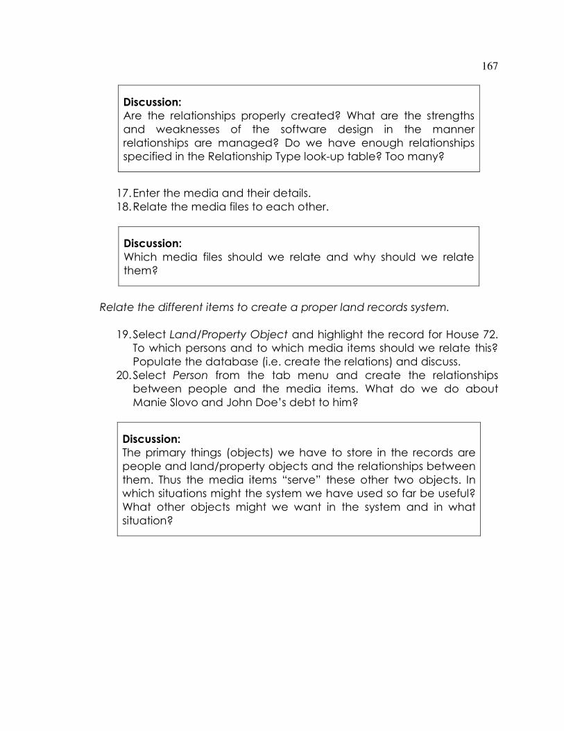
167
Discussion:
Are the relationships properly created? What are the strengths
and weaknesses of the software design in the manner
relationships are managed? Do we have enough relationships
specified in the Relationship Type look-up table? Too many?
17. Enter the media and their details.
18. Relate the media files to each other.
Discussion:
Which media files should we relate and why should we relate
them?
Relate the different items to create a proper land records system.
19. Select Land/Property Object and highlight the record for House 72.
To which persons and to which media items should we relate this?
Populate the database (i.e. create the relations) and discuss.
20. Select Person from the tab menu and create the relationships
between people and the media items. What do we do about
Manie Slovo and John Doe’s debt to him?
Discussion:
The primary things (objects) we have to store in the records are
people and land/property objects and the relationships between
them. Thus the media items “serve” these other two objects. In
which situations might the system we have used so far be useful?
What other objects might we want in the system and in what
situation?

168
PART 3 FORMALISATION / REGULARISATION OF
ALMONDVILLE
Several years and pass and the community decides they want to
formalize their land. The first item needed is a survey plan of the outside
figure of the settlement. Lot holders choose to survey their lots as and
when they want to register their land.
A surveyor Jack Jacobs surveys the outside figure being Lot 1 Almondville
as a land grant and creates a survey plan SP_2015_4567.
Jacobs lodges his survey with the Surveyor General who assigns the above
survey plan number and stores the survey record as SR_2015_100.
This plan then gets registered under a 25 year lease / purchase by
installments scheme as T_A_2015_4376 in the name of the Almondville
Community Trust. (The surveyor General endorses this number on the
survey plan).
In the same survey, SR_2015_100, Jacobs creates lot 2 and lot 3, which are
portions of lot 1. Lot 2 is assigned Survey Plan number SP_2015_4568, and
lot 3 SP_2015_4569. These two subdivisions create a 10 metre wide road to
the south of them.
The Surveyor General “sketches” the subdivisions on the parent Survey
Plan of Lot 1 which is assigned an update number SP_2015_4567_1 to
denote the changes made as a consequence of the subdivisions made in
the survey SR_2015_100.
Lot 2 is transferred to John Doe by deed T_A_2015_4377. Lot 2 includes
House 72.
Lot 3 is transferred to Clare Habermas, John Doe’s sister, by deed
T_A_2015_4378.
In 2017, Manie Slovo claims he owns the property, as John Doe did not
repay his debt, and we go to a community tribunal. We need to get all
the evidence related to the adjudication and titling of the property to
assess the evidence.

169
In the same year, John Doe’s long lost brother challenges John Doe’s
ownership.
In 2020, Clare Habermas dies and lot 3 becomes the property of John
Doe’s family through inheritance.
Land Surveyor Jack Jacobs prepares survey plan SP_2015_567
consolidating the two lots.
Deed T_A_2020_111 transfers lot 3 to John Doe and family
Deed T_A_2020_112 consolidates lots 2 and 3 held by John Doe and family
Discussion:
How do we deal with these various transactions and claims?
How do we query our database to extract the relevant
information in the event of a claim?
Do we have sufficient data to deal with Manie Slovo’s claim and
John Doe’s brother’s claim?
Can we ever have enough information to deal with such claims?
Data Entry
1. Have a look at the Survey Plan SP_2015_4567 and the rest of the
Survey Plans (you may use the term diagram rather than survey
plan).
What is the chain of subdivisions and consolidations that has taken
place?
Enter all the survey plans as media items and their Lot numbers as
Land\Property objects. Enter the Survey Plans as media items in the
following order:
Plan Lot Number / Object
SP_2015_4567
Lot 1 Almondville, outside figure of
settlement.
SP_2015_4568
Lot 2, portion of Lot 1, Almondville

170
SP_2015_4569
Lot 3, portion of Lot 1, Almondville
SP_2015_4567/1
Endorsed to show subdivision creating lots 2
and 3
SP_2020_567
Lot 4 comprising consolidation of lots 2 and
3 into lot 4 Almondville
SP_2015_4568/1 Cancelled as included in consolidation
SP_2015_4569/1 Cancelled as included in consolidation
SP_2015_4567/2 Endorsed to show consolidation of lots 2
and 3 into lot 4 Almondville
Why should we choose this order of entry?
2. Enter the lot numbers as Land\Property objects and then relate
them to the survey plans.
3. What happens to house 72 now? To what should this be related, if
anything?
4. Mark the relevant Survey Plans as Superceded and Lot Numbers as
Extinguished if they are no longer the current document or the lot
has disappeared through consolidation or subdivisions which leave
no remainder.
5. What should we do with the Survey Record numbers assigned by
the Surveyor General of Almondville (Community Surveyor
General?).
Record
Number
Lots
Created
Survey Plans Surveyors
SR_2015_100 Creates Lots
1,2,3
SP_2015_4567,
SP_2015_4568,
SP_2015_4569
Jack Jacobs
We enter SR_2015_100 as a reference item and relate it to the lots
created in the survey and the media items created in the survey.
Relate Jack Jacobs to the Survey Record too.
6. Create Jack Jacobs as a person, describe him as a Land Surveyor in
the description field, and relate the Survey Record and the Survey

171
Plans to him. (E.g. Created plans SP_2015_4567, SP_2015_4568,
SP_2015_4569 by Survey SR_2015_100).
Title Deeds
There are different ways of registering land. We will use a deeds or
improved deeds system, where documents are generated on a word
processor. We can easily use a title based system where every
document is stored individually and linked via a relation. Open the
deeds/titles in MS-Word and browse through the different sections of
them. Have a look at how they are constructed. Could we use the
software to manage these?
Enter and relate the following data.
Title Deed Lawyer Lots People Survey Plan Tenure /
Restriction
T_A_2015
_4376
Catherine
Joan
Renaulds
1 Almondville
Community
Trust
SP_2015_4567 25 year lease
T_A_2015
_4377
Catherine
Joan
Renaulds
2 John Doe SP_2015_4568 25 year lease
T_A_2015
_4378
Catherine
Joan
Renaulds
3 Clare
Habermas
SP_2015_4569 25 year lease
7. Open Deed T_A_2015_4376 first and enter it as a new Reference
File. Discuss and then do the following: Cut and paste what you
think is the relevant text in the deed to the Description field. Repeat
this for all the deeds.
8. Enter the person details for the lawyers.
9. If their details are not in the database already, enter the details of
the people.
10. We do not need to enter the Tenure type as it is in the descriptions.
11. Link the reference instruments to the relevant people, land objects
and survey plans.
12. Once all the data are entered and you feel that the data are
accurate, close the Reference Instruments. Right click on the record
and select Mark as Closed. This is equivalent to registering them.
They now cannot be altered.

172
13. Try to retrieve data which will give us information about the
following:
In 2017, Manie Slovo claims he owns the property (lot 1 and house 72), as
John Doe did not repay his debt, and we go to a community tribunal. We
need to get all the evidence related to the adjudication and titling of the
property to assess the evidence.
In the same year, John Doe’s long lost brother challenges John Doe’s
ownership.
Discussion:
Did we enter either of these two claimants as people?
If we look at the relationships which we have entered
against John Doe, can we track the data which will get
us the necessary evidence?
What should we do in future?
What are the limitations of any land tenure information
system?
14. Enter the details relating to the following:
In 2020, Clare Habermas dies and lot 3 becomes the property
of John Doe’s family through inheritance.
Land Surveyor Jack Jacobs prepares survey plan SP_2020_567
consolidating the two lots.
Deed T_A_2020_111 transfers lot 3 to John Doe and family
Deed T_A_2020_112 consolidates lots 2 and 3 held by John
Doe and family
Discussion:
1. How do we use the above exercises to design a land records
system that can include both customary land tenure data and
surveyed and registered land data? Discuss this is general terms, not
your own local situation.

173
2. How can you use this to develop an integrated Land information
System in your local situation?
3. Design a land information system and a tutorial for one of the
following:
a. A land information system in a land professional’s office (your
own office)
b. A micro-finance system for housing
c. A mortgage system for housing
d. A local level surveyor general’s office
e. A land regularisation system
3. DESIGNING A PROJECT
There are a range of applications and a mix of applications for which The
Talking Titler software can be used as an administrative tool. It is critical
that you prepare a rigorous design for the system and write down proper
procedures for using the system. The system allows a great deal of
flexibility; flexibility which will allow you to create a complete mess if you’re
not careful! Therefore, it is vital that procedures and rules are properly
documented.
STEP 1: List Entities
Let’s first list the various references, or entities, we might be interested in
such as the following:
Persons
A person may be a client; more than one person may be the client
A person may be a landholder; more than one person may be the
holder
A person may be claiming a right in land
A person may be a neighbour to one of the parcels being surveyed
A person may be a partial rights holder (e.g. mineral rights holder,
mineral lease holder, right-of-way holder, usufruct holder)
A person may be a company or a trust or similar business entity
A person may be a government department

174
A person may be the holder of partial rights in a parcel (e.g. servitude
(easement) or lease)
A person may be related to another person (e.g. parent – child, cousin
etc, clan, sub-clan, lineage group) which gives them a right in land
A person has an identity document, an address and possibly a
photograph (media)
A person may appear in many media items
Possible Reference Entities
You should choose one of the following as the reference entity. If the
others in this list appear in your database, they should be listed as media.
Underlying Titles and/or Deeds
Partial Rights (e.g. Servitudes, Easements, Right of Way, Lease, Usufruct,
profit a Prendre) and documents (e.g. title instrument) which define
them
Property File
Rent Card
Occupation Permit
Parcel Number (possible reference if parcel based information system
as opposed to property ownership reference)
Object Number (e.g. shack number, house number)
Possible Media Entities
Survey
A survey will have a survey record number; either from the Surveyor
General or an in house reference number e.g. SR_2009_1234. We
may wish to break the survey down into its components
Survey Plans / Diagrams – legal documents created in the survey
Parcels
Parcels may be those that are being surveyed or affected by a
survey

175
A parcel can have a real right over another parcel. E.g. a servitude /
easement can be in favour of parcel A over parcel B.
A BR
oa
d
Easement / Servitude Right of Way
Dominant Tenement
Parc el A has a rightover parc el B
Servient Tenement
A 3-d Object of Land Rights such as a strata space, section or
condominium unit, house or a shack
Physical Feature
A physical feature will probably be something like a power line, a
river, a tree, a building or a part of a building (e.g. an apartment or
garage).
A physical feature may be represented on a Survey Plan / diagram
or other media form
Vegetable Garden
Maps e.g. 1:50,000 sheets incorporating the area under survey
Cadastral Information System Plan – government maps of cadastral
boundaries and other cadastral information
Geodetic Control Coordinate File
Satellite Images
Topographic Plan / DTM file of area under survey
Aerial Photographs

176
Survey Records from previous surveys which have a bearing on the
current survey
Photographs of evidence which may be relevant to current survey and
to other surveys
Videos of evidence which may be relevant to current survey and to
other surveys. It may also be evidence relating to objects, persons and
for general historical evidence.
Audio / Sound File
SAR files
LIDAR files
Geophysical survey data
GIS Coverages
Cadastral Information System Plan – government maps of cadastral
boundaries and other cadastral information
Written documents
STEP 2: DEVELOP QUESTIONS YOU MIGHT ASK OF THE SYSTEM
• What is the Survey Record Number?
• Is there a reference to a statutory consent (e.g. Subdivision Approval)
• Which parcels are directly affected by this survey?
• Which Cadastral Information Plans underlie the area of interest?
• Which existing survey plans do I need to examine (e.g. neighbouring
parcels, partial rights)
• Which previous surveys (Survey Record Numbers) do I need to examine
and reference as part of the survey process (recursive relationship)
• Which topographic maps (e.g. 1:50,000 sheet) underlies this survey?
• Which Surveys are fall within the borders of a particular map sheet (How
many of the reference entities are contained in one of the media?)
• Which people are affected by the survey?

177
• Which people have registered or recorded rights over a parcel or
object?
• Which people are claiming a particular parcel?
• Who are the clients?
• Do they have representatives and sub-contractors?
• What other relationships between people are relevant to the survey?
• What are the interpersonal relationships in this population that may give
rise to land rights or expectations of land rights?
• Which people are affected by the process; who are the stakeholders
and other role players? What is their interest?
• What are the Titles / Deeds affecting the survey?
• What partial right titles / deeds affect the survey?
• Which people lay claim to these?
• What are the Survey Plans that are being generated by this survey?
• What digital survey files (e.g. DTMs, Geodetic coordinate lists) affect the
survey
• Which multimedia files are relevant to the survey (including ones
generated in previous surveys and as part of this survey)?
• Which parcels are featured in these multimedia files?
• Where is the original evidence stored?
• Which people feature in these multimedia files?
• Which Physical features feature in these multimedia files?
• What other multi-media files are related to each other (e.g. sound file
and video file recorded at same time, previous video is relevant to new
one – different witnesses or contradictory testimony)
STEP 3: Develop Prefixes which uniquely define the entities
We want a prefix which defines a particular entity or reference. For
example we prefixed a survey Record by SR and the suffix is the year in
which it was created SR123/2009. It is preferable that each type of entity
has a unique way of referencing and identifying it. You should not use the
same identifier for two different objects either, even if they are of the
same type. See Appendix C.
STEP 4: Document the Relationships between Entities
I suggest you draw a matrix on a large sheet of paper. List all the entities
along the side and along the top. Then in the square matching two
entities, write the possible relationships between them. Remember an
entity can have a relationship with itself. E.g. A dog fights other dogs. The

178
following is a simple table to determine the relationships between different
entities.
Entities Dog Cat License Owner
Dog fights other chases has
Cat fights other has
License
Owner owns owns purchases
STEP 5: DEVISE A SCHEME TO RELATE THE DIFFERENT ENTITIES AS PER THE
TABLE IN STEP 3
How do these entities relate to each other? The table above should
provide these. Following this you should be able to determine if an entity is
classed as Media or Reference. Remember a video can be related to
another video and each of them can be related to a number of different
people and parcels
STEP 6: LIST THE ENTITIES IN THE LOOK UP TABLE OF REFERENCES AND MEDIA
See appendix A to this manual
STEP 7 PROTOTYPE THE SYSTEM
Enter data and relate them. Play with the system and see what sort of
queries you will require.
Then write down a rigorous set of data entry steps and methods of
performing specific types of queries. This step is essential if you want a
working system. The software allows a great deal of flexibility, which also
means you can create a spaghetti system if you are not careful – you can
create meaningless relationships between data objects.
You also need to write down an independent system of checking and
quality management. Sign off on a record when it checked and properly

179
entered. Close a record once no more editing should take place e.g.
when a title is registered, the record relating to it should be closed.
STEP 8 DEVELOP SYSTEM BACK UP AND ARCHIVING PROCEDURES
This is a new software system and it is easy to delete the database
inadvertently. Develop procedures to do monthly archives of the data
and weekly backups. ALWAYS back up the database file OM.mdb
before you install a software update. You may lose your entire
database otherwise.
EXAMPLE: LAND TENURE RECORDS
Land tenure records can be legally registered records or merely a record
of claims to rights. The latter are commonly referred to as regularization or
adjudication records. They may also be kept as a record of information for
land claims. Video and audio files can be organized in the system as oral
(undocumented) evidence.