development and applications optical interferometric
TRANSCRIPT

I
NASA Technical Memorandum 100299
Development and Applications of Optical Interferometric Micrometrology in the Angstrom and Subangstrom Range
James L. Lauer Rensselaer Polytechnic Institute Troy, New York
and
Phillip B. Abel Lewis Research Center Cleveland, Ohio
El 88- 231 96 [EAS&-TH-100299) D E V E L O P H E N T AND APPLICATIONS OF O P T I C A L I NT EBFERORETR IC HICROl4ETROLOGY I N THE ANGSTROH AND SUBABGSTROH RANGE [ N B S A ) 2 2 P CSCL 14B Unclas
G3/35 01US907 Prepared for the 34th International Instrumentation Symposiwn sponsored by the Instrument Society of America Albuquerque, New Mexico, May 2-5, 1988
r
i
i
i I i
I
P

DEVELOPMENT AND APPLICATIONS OF OPTICAL INTERFEROMETRIC
MICROMETROLOGY I N THE ANGSTROM AND SUBANGSTROM RANGE
James L. Lauer* Department o f Mechanical Engineer ing,
A e r o n a u t i c a l Eng ineer ing and Mechanics Rensselaer P o l y t e c h n i c I n s t i t u t e
Troy, New York 12180-3590
and
P h i l l i p B . Abel N a t i o n a l Ae ronau t i cs and Space A d m i n i s t r a t i o n
Lewis Research Center Cleveland, Ohio 44135-3191
SUMMARY
The r e c e n t development of t h e scanning e l e c t r o n t u n n e l i n g microscope and t h e atomic f o r c e microscope r e q u i r e s a b s o l u t e standards for measurements i n t h e angstrom and subangstrom range. O p t i c a l i n t e r f e r o m e t r y w i t h l a s e r s and m u l t i - p l e mode l a s e r resonances can p r o v i d e abso lu te measurements as t h e l a s e r wave- l eng ths a r e v e r y a c c u r a t e l y known. A key f e a t u r e of such measurements i s t he use o f p i e z o e l e c t r i c c r y s t a l s as t r a n s l a t o r s of t h e h i g h e s t accuracy f o r very smal l d i s t a n c e s . However, t h e dimensional changes of these c r y s t a l s r e s u l t i n g from e l e c t r i c a l p o t e n t i a l changes depend on many v a r i a b l e s , among them t h e method o f mount ing, so t h a t accu ra te c a l i b r a t i o n s a r e necessary.
S t a r t i n g from advances i n o p t i c a l me t ro logy made by p h y s i c i s t s t r y i n g t o f i n d g r a v i t y waves, advances which l e d t o measurements down to 10-5 A , t h e au tho r designed and b u i l t a much s i m p l e r system for t h e angstrom range. major l i m i t i n g f a c t o r s w e r e mechanical v i b r a t i o n s , a i r c u r r e n t s , thermal changes and l a s e r i n s t a b i l i t i e s .
The
INTRODUCTION
The atomic t h e o r y goes back t o t h e Greeks , b u t s i n c e atoms a r e too smal l t o be seen t h e r e always remained a l i n g e r i n g doubt about t h e i r e x i s t e n c e . t h e y " r e a l " or j u s t conven ien t t h e o r e t i c a l concepts? A s o l i d s u r f a c e i s seen as impregnable, b u t if i t c o n s i s t s of atoms spaced a p a r t i n r e g u l a r o r n o t so r e g u l a r l a t t i c e c o n f i g u r a t i o n s , then i t i s mostly open and o n l y appears t o be cont inuous, perhaps on account o f r a p i d mo t ion o f t h e e lementary p a r t i c l e s . X-ray d i f f r a c t i o n p r o v i d e s evidence o f l a t t i c e s t r u c t u r e s o f s o l i d s and o f spacings between t h e "atoms" o f t h e o r d e r o f angstroms. The d i f f r a c t i o n p a t - t e r n s show o n l y the F o u r i e r t rans fo rms of t h e r e a l l a t t i c e o r s o - c a l l e d r e c i p - r o c a l l a t t i c e s , and t h e r e f o r e a r e s t i l l o n l y c o n s t r u c t s . Moreover, x-rays g e n e r a l l y cannot p r o v i d e s u r f a c e maps. Using m u l t i p l e beam o p t i c a l i n t e r - ferometry Tolansky was a b l e t o show t h a t some f l a t su r faces o f c r y s t a l s such
A r e
* A l s o Summer F a c u l t y F e l l o w a t NASA Lewis Research Center i n 1987.
as q u a r t z o r mica can c o n t a i n s teps and t h a t o r g a n i c c r y s t a l l i n e m a t e r i a l s , such as po lye thy lene of h i g h d e n s i t y , can have a s u r f a c e s t r u c t u r e o f p lanes and steps between them, t h a t a re o f mo lecu la r dimensions. He produced su r face maps by noncon tac t i ng techniques; however, r e s o l u t i o n was atomic or mo lecu la r , i . e . , a f e w angstroms, o n l y i n t h e d i r e c t i o n normal t o t h e su r face . H i s l a t - e r a l r e s o l u t i o n was o r d e r s o f magnitude poore r and he c o u l d n o t " s e e " t h e atoms or molecules on the surface.
Low energy e l e c t r o n d i f f r a c t i o n techniques aga in do n o t p e r m i t t h e "see ins " o f atoms and, moreover, a re suspect because o f t h e i n t e r a c t i o n o f " f o r e i g n " bombarding e l e c t r o n s w i t h the e l e c t r o n s su r round in su r face : The bombardment, though o f low energy, must s t i l l su r face . E l e c t r o n d i f f r a c t i o n techniques, moreover, r e q u i r e i n t h e samples. These techniques have a l s o r e l a t i v e l y poor
The announcement of t h e i n v e n t i o n and successful o p e r a t e l e c t r o n t u n n e l i n g microscope p r i m a r i l y u s e f u l f o r e l e c t r i c a sur faces, and, a l i t t l e l a t e r , o f an atomic f o r c e microscope a p p l i c a b l e t o almost any su r face , were t h e r e f o r e immediate ly
t h e atoms o f t h e n t e r a c t w i t h the long-range o r d e r a t e r a l r e s o l u t i o n .
on o f a scanning l y conduc t ing p o t e n t i a1 1 y
g ree ted as major breakthroughs. These ins t rumen ts can p r o v i d e t h e l a t e r a l r e s o l u t i o n necessary t o p r o v i d e atomic s u r f a c e maps. O p t i c a l techniques a re s t i l l needed t o c a l i - b r a t e these new tools, b u t even t h e most s e n s i t i v e o p t i c a l techniques a lone cannot p r o v i d e the l a t e r a l r e s o l u t i o n . The work desc r ibed i n t h i s paper dea ls w i t h the o p t i c a l techniques considered a p p r o p r i a t e for these c a l i b r a t i o n s , b u t they can be o f use e l s e w h e r e . A s a m a t t e r o f f a c t , some o f t h e o p t i c a l t e c h - n iques were developed i n connec t ion w i t h t h e search, so f a r i n v a i n , f o r g r a v i t y waves and can have ex t reme ly h i g h s e n s i t i v i t i e s . One o f these u l t r a - s e n s i t i v e techniques, f l u o r e s c e n c e e x c i t e d by evanescent waves, was never used for metro logy b u t i s l i k e l y t o f i n d a p lace , and i s t h e r e f o r e i n c l u d e d i n t h i s paper . The technique adapted f o r ou r exper imenta l c a l i b r a t i o n setup, a v a r i a - t i o n o f l a s e r i n t e r f e r o m e t r y , t u r n e d o u t to be adequate and w e l l - s u i t e d f o r t h e purpose.
For completeness a b r i e f r e v i e w o f t h e new s u r f a c e a n a l y s i s tools precedes t h e d i s c u s s i o n o f o p t i c a l techniques.
SCANNING TUNNELING MICROSCOPE AND ATOMIC FORCE MICROSCOPE
Scanning Tunnel ing Microscope
The scanning e l e c t r o n t u n n e l i n g microscope (STM) o f B i n n i g and Rohrer ( r e f s . 1 and 21, developed o n l y a f e w years ago, has e x c e l l e n t l a t e r a l r e s o l u - t i o n and does n o t a f f e c t t h e su r face which i t scans w i t h atomic r e s o l u t i o n . I t p rov ides su r face maps o f t h e e l e c t r o n d e n s i t i e s as a f u n c t i o n o f p o t e n t i a l . H igh concen t ra t i ons o f e l e c t r o n s correspond t o t h e c louds su r round ing atoms. The STM i s b a s i c a l l y v e r y s imple: A v e r y sharp m e t a l l i c t i p i s h e l d a t a con- s t a n t smal l d i s t a n c e (subnanometer) above t h e t e s t s u r f a c e moving i n t h e x or y d i r e c t i o n . E l e c t r o n s tunne l across t h e gap i n t o t h e s u r f a c e i f t h e t i p i s b iased n e g a t i v e l y w i t h r e s p e c t t o t h e su r face , o r v i c e ve rsa i f t h e b i a s i s reversed. The b i a s p o t e n t i a i s v e r y low, from m i l l i v o l t s t o a f e w v o l t s . The t u n n e l i n g e l e c t r o n s i n d i c a t e t h e l o c a l e l e c t r o n d e n s i t i e s i n terms o f changes i n t h e t u n n e l i n g c u r r e n t , wh ch depends e x p o n e n t i a l l y on t h e t i p - t o - s u r f a c e
2

separa t i on , and i s t y p i c a l l y an o r d e r o f magnitude fo r eve ry angstrom o f sepa- r a t i o n . By scanning t h e t i p across the su r face an image i n t h e l a t e r a l d i r e c - t i o n i s achieved, whose r e s o l u t i o n depends on t h e s i z e and shape o f t h e t i p ( 2 t o 3 A ) . The v e r t i c a l r e s o l u t i o n depends on t h e mechanical and e l e c t r o n i c s t a b i l i t y o f t h e i n s t r u m e n t and i s now t y p i c a l l y 0.1 A . H o r i z o n t a l scanning i s c a r r i e d o u t w i t h X- and Y - p i e z o e l e c t r i c t r a n s l a t o r s , w h i l e t h e t i p i s h e l d a t a cons tan t d i s t a n c e from t h e su r face by a t h i r d p i e z o e l e c t r i c dev i ce .
The t u n n e l i n g i s a "mys te r ious " way by which e l e c t r o n s flow th rough the gap between t h e t i p and t h e su r face even through a vacuum. I t can be e x p l a i n e d o n l y by quantum mechanics, where e l e c t r o n s a re rep resen ted as e l e c t r o m a g n e t i c waves and, j u s t as l i g h t , can t r a v e r s e a vacuum. P h y s i c a l l y t u n n e l i n g i s read- i l y d i f f e r e n t i a t e d from o r d i n a r y e l e c t r o n f l o w by t h e exponen t ia l dependence on gap w i d t h . An analogy t o e l e c t r o n t u n n e l i n g i s l i g h t t u n n e l i n g between two p a r a l l e l p lanes when i n c i d e n t a t angles g r e a t e r than c r i t i c a l . Th i s i s taken up i n a l a t e r s e c t i o n .
The a b i l i t y o f t h e STM t o o b t a i n the h i g h h o r i z o n t a l and v e r t i c a l r e s o l u - t i o n ment ioned has been a t t r i b u t e d t o f o u r main f e a t u r e s ( r e f . 4 ) :
( 1 ) P i e z o e l e c t r i c t ransducers can achieve r e s o l u t i o n b e t t e r than 0.01 nm over a range o f severa l micrometers.
(2) The mechanical d r i f t r a t e s a t t a i n a b l e ( l e s s than 1 nm/min> a r e i n s i g - n i f i c a n t or can be c o r r e c t e d f o r ove r t h e t y p i c a l image a c q u i s i t i o n t i m e o f 1 sec t o 5 min.
( 3 ) V i b r a t i o n i s o l a t i o n p reven ts b u i l d i n g v i b r a t i o n and a c o u s t i c n o i s e from a f f e c t i n g t h e sample- t ip assembly.
( 4 ) The r a p i d v a r i a t i o n of t he t u n n e l i n g c u r r e n t w i t h d i s t a n c e l o c a l i z e s t h e c u r r e n t a t t h e v e r y end o f the t i p .
Atomic Force Microscope
The m o s t r e c e n t method t o d a y o f s e e i n g atoms on s u r f a c e s i s t h e a t o m i c f o r c e microscope (AFM) o f B i n n i g , Quate, and Gerber ( r e f . 3 ) . Th is i n s t r u m e n t senses m inu te face . I t p r o v i d e s n o n d e s t r u c t i v e su r face p r o f i l o m e t r y a t a r e s o l u t i o n o f be t - t e r than 10 nm, and perhaps down t o t h e atomic l e v e l . No s t y l u s p r o f i l o m e t e r can match t h i s performance. The AFM makes use o f t h e f i r s t t h r e e f e a t u r e s o f t h e STM l i s t e d above b u t d e t e c t s the f o r c e between t h e t i p and t h e s u r f a c e by t h e d e f l e c t i o n o f the c a n t i l e v e r on which the t i p i s mounted. Th is d e f l e c t i o n can be measured by means o f an STM a t tached t o t h e same c a n t i l e v e r . I t can a l s o be measured by o p t i c a l i n t e r f e r e n c e ( r e f . 4 ) . A s p o i n t e d o u t i n r e f e r - ence 4, t h e AFM goes beyond t h e c a p a b i l i t i e s o f s imple p r o f i l o m e t r y , because i t can q u a n t i t a t i v e l y measure p h y s i c a l , chemical , magnet ic , f r i c t i o n a l , and e l e c t r o s t a t i c i n t e r f a c i a l f o r c e s w i t h very h i g h s p a t i a l r e s o l u t i o n . I n t h i s a p p l i c a t i o n t h e AFM i s r e l a t e d t o a much l e s s s e n s i t i v e dev i ce desc r ibed by Tabor and W i n t e r t o n ( r e f . 5) and developed by I s r a e l a c h v i l i and coworkers ( r e f . 6). I n c o n t r a s t t o STM, which e s s e n t i a l l y can o n l y be used w i t h e l e c t r i - c a l conductors , AFM can a l s o be used w i t h i n s u l a t o r s .
t o 10-8 N ) f o r c e s between a sharp t i p and a sample sur-
3
I n the f o l l o w i n g s e c t i o n s we d i scuss o p t i c a l methods, m a i n l y i n t e r f e r - ometry, o f s u f f i c i e n t r e s o l u t i o n t o measure AFM d e f l e c t i o n s . They have an advantage ove r STM as a m e t r o l o g i c a l dev i ce , i n t h a t t hey p r o v i d e abso lu te d i s t a n c e , i . e . , t hey do n o t r e q u i r e c a l i b r a t i o n by a d i f f e r e n t procedure.
REVIEW OF OPTICAL METROLOGY WITH ULTRAHIGH S E N S I T I V I T Y
O p t i c a l Resonators
I n t h e e a r l y 1970's much e f f o r t was expended t o d e t e c t t h e e x i s t e n c e o f g r a v i t y waves. smal l d isp lacements were exp lo red . One o f t h e b e s t was t h a t o f Boersch and coworkers ( r e f . 71, which c l a i m s a b i l i t y t o measure l e n g t h s h i f t s down t o 10-5 A . ment i s a three-mode He/Ne l a s e r f o r which t h e f requency o f one a x i a l mode can be tuned independen t l y from t h e o t h e r modes by a t h i r d , p a r t i a l l y r e f l e c t - i n g and p a r t i a l l y t r a n s m i t t i n g mirror. The coupled resona to r thus produced causes a f requency s h i f t which i s p r o p o r t i o n a l t o t h e change o f t h e o p t i c a l p a t h l e n g t h between t h e t h i r d mirror and t h e n e i g h b o r i n g l a s e r mirror. By o b s e r v i n g t h e bea t f requency o f t h e tube, o p t i c a l p a t h v a r i a t i o n s o f A a r e measurable.
For t h i s purpose v a r i o u s methods capable o f measuring v e r y
F i g u r e 1 shows t h e exper imen ta l setup s c h e m a t i c a l l y . I t s b a s i c e l e -
I For t h i s s y s t e m t o be used w i t h an AFM t h e " t h i r d " mirror must be coupled to the cantilever. This should not be difficult. A piezoceramic translator moves t h i s mirror. Frequency modu la t i on techniques reduced t h e n o i s e . The l a s e r must be w e l l s t a b i l i z e d by a se rvo l oop .
Laser I n t e r f e r o m e t e r o f Moss, M i 1 l e r , and Forward
T h i s i n s t r u m e n t was a l s o des igned f o r g r a v i t y wave d e t e c t i o n ( r e f . 8). The p r i n c i p a l d i f f e r e n c e between i t ( f i g . 2) and t h e c l a s s i c a l two-beam Miche lson i n t e r f e r o m e t e r i s t h e p i e z o e l e c t r i c d r i v e r on one o f t h e i n t e r f e r - ometer mirrors. Th is d r i v e r generates subangstrom (3x10- l4 m) v i b r a t i o n s o f known amp l i t ude . The s l i g h t l y asymmetr ic c o n f i g u r a t i o n p reven ts r e f l e c t e d energy from r e e n t e r i n g t h e l a s e r . I t a l s o p r o v i d e s two o u t p u t s so t h a t two p h o t o d e t e c t o r s can be used i n a ba lanced b r i d g e t o reduce s i g n a l s due t o l a s e r a m p l i t u d e no ise . The o u t p u t o f t h e matched d e t e c t o r b r i d g e i s a m p l i f i e d w i t h a tuned a m p l i f i e r and then mixed w i t h t h e d r i v i n g s i g n a l i n a m u l t i p l i e r t o t r a n s f o r m t h e s i g n a l f requency down t o dc. The s i g n a l i s then passed th rough a 2 . 5 Hz bandwidth low pass f i l t e r t h a t determines t h e system bandwidth. Th is s i g n a l i s then squared t o g i v e an o u t u t p r o p o r t i o n a l t o power and recorded. A d isp lacement s e n s i t i v i t y o f 3 . 5 ~ 1 0 - $6 m was a t t a i n e d .
For use w i t h t h e AFM t h e M iche lson Mirror on t o p o f f i g u r e 2 would be cou- p l e d t o t h e c a n t i l e v e r . The d i s t a n c e o f mirror t r a v e l corresponding t o two success ive maxima o f o u t p u t s i g n a l would be equal t o h a l f a l a s e r wavelength and s m a l l e r d i s tances would be l i n e a r l y p r o p o r t i o n a l t o t h a t d i s t a n c e . The e n t i r e system, i n t e r f e r o m e t e r and AFM, would be mounted on an o p t i c a l , v i b r a - t i o n i s o l a t i o n t a b l e .
I 4

Two Frequency Laser I n t e r f e r o m e t e r
The s i n g l e f requency l a s e r i n t e r f e r o m e t e r has two major drawbacks which subsequent des ign c o u l d c o r r e c t : ( 1 ) v e r y c r i t i c a l mirror a l i gnmen t and ( 2 ) dependence o f t h e t r i g g e r i n g l e v e l o f the photon d e t e c t o r on t h e i n t e n s i t y o f t h e l i g h t beam and t h e r e f o r e on i n t e n s i t y v a r i a t i o n s o f t h e l a s e r source. The f i r s t d i f f i c u l t y was c o r r e c t e d by the s u b s t i t u t i o n o f cube co rne rs (some- t i m e s c a l l e d corner cubes) f o r t h e mirrors, and t h e second by t h e use o f a tw frequency l a s e r ( r e f . 9 ) . i n g beams p a r a l l e l t o t h e i r ang le o f i nc idence r e g a r d l e s s o f how a c c u r a t e l y they a re a l i g n e d to t h e beam. An e x c e l l e n t example o f t h e two f requency l a s e r i n t e r f e r o m e t e r i s t h e o p t i c a l heterodyne p r o f i l o m e t e r o f Sommargren ( r e f . 10). A s t h e name i n d i c a t e s t h i s i n s t r u m e n t was designed t o measure s u r f a c e p r o f i l e s . I t does t h i s w i t h a h e i g h t s e n s i t i v i t y o f 1 A , b u t should be r e a d i l y adaptable t o d isp lacement measurements, f o r example by making use o f a r e f e r e n c e s u r f a c e v i b r a t i n g a x i a l l y on a p i e z o e l e c t r i c mount. r o t a t i n g h i s samples on a t a b l e and used the p o s i t i o n on t h e s u r f a c e t r a v e r s e d by t h e a x i s as h i s r e f e r e n c e . Two o r t h o g o n a l l y p o l a r i z e d beams o f s l i g h t l y d i f f e r e n t f requency were focused on the su r face t o be measured. A magnet ic f i e l d on t h e l a s e r source produced these beams by t h e Zeeman e f f e c t . A s l i g h t l a t e r a l d isp lacement was e f f e c t e d by a Wol laston p r i sm. The phase o f t h e bea t f requency o f the i n t e r f e r i n g r e t u r n beams i s d i r e c t l y p r o p o r t i o n a l t o t h e a x i a l d isp lacement between t h e sample and r e f e r e n c e l o c a t i o n s .
The cube co rne rs have t h e c h a r a c t e r i s t i c o f r e f l e c t -
Sommargren c r e a t e d modu la t i on by
Mult ip le-Beam I n t e r f e r o m e t r y ( M B I )
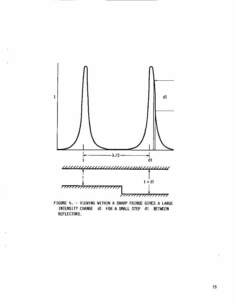
Suppose p a r a l l e l monochromatic l i g h t impinges on and t r a v e r s e s two p a r a l - l e l r e f l e c t i n g su r faces a t a s l i g h t ang le . Because o f i n t e r f e r e n c e between t h e s t r a i g h t - t h r o u g h and t h e t w i c e r e f l e c t e d beams, which i s de layed i n phase, a c i r c u l a r f r i n g e p a t t e r n can be observed i n the f o c a l p lane o f a l e n s on a screen p a r a l l e l to t h e s u r f a c e . The o p t i c a l arrangement ( f i g . 3 ) can be con- s i d e r e d a m o d i f i c a t i o n o f t h e c l a s s i c a l Newton's r i n g s exper iment . Fabry and P e r o t used such an i n s t r u m e n t t o measure t h e wavelengths o f a r c r a d i a t i o n s w i t h extreme accuracy. For t h a t purpose t h e r e f l e c t i v i t y ( g i v i n g r i s e t o mul- t i p l e beams) o f the su r faces had t o be made ve ry h i g h , e.g. by s i l v e r i n g , f o r then t h e sharpness ( f i n e s s e ) o f the f r i n g e s increases d r a m a t i c a l l y . Tolansky ( r e f . 1 1 ) a p p l i e d t h i s p r i n c i p l e i n t h e converse mode. He adapted i t t o f i n d s teps on su r faces by examin ing t h e change i n i n t e n s i t y near t h e peak o f an i n t e r f e r e n c e maximum. I n t h e neighborhood o f h a l f t h e peak i n t e n s i t y a s tep h e i g h t ( f i g . 4 ) o f 3 A i s e a s i l y observable, indeed v i s u a l l y obse rvab le , w i t h r a d i a t i o n o f t h e green (A = 5460 8 ) mercury l i n e . " . .a . . .notewor thy way o f i n d i c a t i n g t h e extreme s e n s i t i v i t y o f t h i s o p t i c a l system i s t h e f a c t t h a t a s i n g l e l a t t i c e spacing i n mica (20 A ) makes no l e s s than a 50 pe rcen t a l t e r a t i o n i n t r a n s m i t t e d i n t e n s i t y ! "
To quote Tolansky ( r e f . 12):
S ince M B I i s a l r e a d y so s e n s i t i v e by o r d i n a r y o b s e r v a t i o n , phase- lock d e t e c t i o n w i t h e l e c t r o n i c d e t e c t o r s and minute d isp lacements by p i e z o c r y s t a l s should make i t a t l e a s t an o r d e r o f magnitude more s e n s i t i v e .
5

Evanescent Wave D e t e c t i o n
The use o f evanescent wave d e t e c t i o n (EWD) f o r t h e measurement o f v e r y smal l d isplacements has n o t been ment ioned i n t h e l i t e r a t u r e t o o u r knowledge, a l t hough work desc r ibed for o t h e r o b j e c t i v e s would seem t o make EWD a l o g i c a l candidate. c a l l y e q u i v a l e n t t o STM.
E lec t romagne t i c t h e o r y ( r e f . 13) s t a t e s t h a t a p l a n e wave p ropaga t ing through an o p t i c a l l y denser medium ( s u f f i x 1) and imp ing ing on t h e i n t e r f a c e s e p a r a t i n g an o p t i c a l l y r a r e medium ( s u f f i x 2) w i t h an i n c i d e n c e angle 8 i ( taken from t h e normal) w i l l be t o t a l l y r e f l e c t e d i f 81 i s l a r g e r than t h e c r i t i c a l angle 8, = s i n - l ( n 2 I n l ) . l e s s p e n e t r a t e t h e r a r e r medium i n t h e form o f an evanescent d i s t u r b a n c e (some- t imes c a l l e d an "evanescent wave"). The energy d i s t r i b u t i o n a long t h e z -ax i s , normal t o t h e i n t e r f a c e , decays e x p o n e n t i a l l y a c c o r d i n g t o
I t i s p a r t i c u l a r l y a p p r o p r i a t e here, for i t can be considered o p t i -
P a r t o f t h e i n c i d e n t energy w i l l n e v e r t h -
The c h a r a c t e r i s t i c p e n e t r a t i o n depth, A , v a r i e s w i t h t h e i n c i d e n c e angle, 8 i , as
where X, i s t h e wavelength o f l i g h t i n vacuum. A i s independent o f t h e p o l a r i z a t i o n o f t h e e l e c t r o m a g n e t i c wave.
The "evanescent" d i s t u r b a n c e t h a t t r a v e l s i n t o t h e r a r e r medium can be found i n d i f f e r e n t ways, one o f them by p u t t i n g a second p a r a l l e l s u r f a c e w i t h i n t h e decay d i s t a n c e o f t h e f i r s t boundary. g i v e s r i s e t o a r e a l wave i n t h e second medium, which can be observed ( f i g . 5 ) . Th is i s t h e c l a s s i c a l method o f " f r u s t r a t i n g " t h e r e f l e c t i o n ( r e f . 14 ) . The e lec t romagne t i c wave i s s a i d t o " t u n n e l " across t h e gap, analogous t o e l e c t r o n t u n n e l i n g i n t h e STM. o f i n t e n s i t y on gap w i d t h g i v e n by e q u a t i o n ( 1 ) . nescent energy i s t h e r e f o r e an o p t i c a l ana log t o STM as a d is tance-measur ing method or, more to t h e p o i n t perhaps for measur ing t h e l e v e r d e f l e c t i o n i n t h e AFM, a method o f d e t e r m i n i n g angu la r d isp lacement i n accordance w i t h equa- t i o n ( 2 ) . I t should be noted t h a t b o t h o f these equa t ions a r e approximate, b u t s u f f i c i e n t f o r o u r purposes. i s g i v e n by H a r r i c k ( r e f . 15) .
The evanescent wave then
Another analogy w i t h STM i s t h e e x p o n e n t i a l dependence The d e t e r m i n a t i o n o f t h e eva-
A summary of r e c e n t work on these equa t ions
A most s e n s i t i v e techn ique o f c o u p l i n g t o t h e evanescent wave i s by f l u o - rescence ( r e f . 16). I f medium 2 c o n s i s t s o f an aqueous s o l u t i o n o f f l u o r e s c e i n i n low enough c o n c e n t r a t i o n t o a v o i d quenching by i n t e r m o l e c u l a r i n t e r a c t i o n , t h e f l uo rescence p i c k e d up by a p h o t o m u l t i p l i e r i s a v e r y s e n s i t i v e f u n c t i o n o f angle (eq. ( 2 ) ) . H a r r i c k ( r e f . 17) p resen ts t a b l e s t o show t h i s dependence fo r a t t a i n a b l e i n d i c e s o f r e f r a c t i o n . F i g u r e 6 c o n t a i n s a schematic diagram o f an angular d isp lacement d e t e c t o r based on t h e f l u o r e s c e n c e e x c i t e d by t h e evanes- cen t wave.
6

EXPERIMENTAL
Atomic Force Microscope Using Optical Interference to Detect Lever Deflection
I
Figure 7 contains a schematic diagram of the atomic force microscope, according to McClelland and coworkers (ref. 4 1 , to which reference was made in an earlier section of this paper. is necessary to achieve a resolution of -0.1 nm (1 A ) perpendicular to the sur- face for levers of reasonable spring constant. Binnig and coworkers (ref. 2 ) achieved this and they also achieved a resolution of -10 nm parallel to the surface.
To sense forces of the order of 10-8 N it
Our experimental effort was limited to obtaining the vertical resolution. The deflection of the lever was to be measured while moving the sample along x and y to scan its surface at a distance close to the tip. For this purpose piezoelectric translators are necessary.
A recent article by Atherton (ref. 19) reviews the state of the art of the piezoelectric translators. (<1 kV). pate very little heat. Positioning to better than 1 nm is now possible with a linearity of 0.1 percent and a response time of less than 0.5 msec with no detectable hysteresis for small displacements.
Most of today's models operate at low voltage They are very stiff and can move fast and with great force and dissi-
Laser Interferometer for AFM
Figure 8 shows schematically our laser interferometer for the AFM. Radia- tion from the He/Ne laser is split by the beamsplitter cube into a part that falls on a screen for visual alignment or on a photocell for possible laser stabilization and into another part that traverses the optical reference flat and i s then focused by the lens onto the reflector (cantilever beam or other mechanical element whose small deflection is to be determined). In the drawing the reflector is attached to a piezoelectric tube whose characteristics are to be determined. After reflection the beam is returned to the beamsplitter and split again into (1) a portion that barely bypasses the laser and falls on a screen where the interference fringes generated by interference with the por- tion of the beam originally reflected by the reference flat can be observed and ( 2 ) a portion that passes the aperture and is ultimately detected by the photodiode. A s pointed out in the discussion of the Moss et al. (ref. 8) laser interferometer, the laser radiation should not be reflected back into the laser cavi ty .
The optical system shown is a combination of the laser interferometer of Moss et al. (ref. 8) and the multiple-beam interferometer of Tolansky (refs. 1 1 and 12) and others. All the optics are of 1 cm or somewhat larger diameter. The lens is a 10 cm focal length (lox) biconvex lens and all the optical surfaces are flat to 0.1 wavelength or better. The optical flat is antireflection-coated on one side. All the components are rigidly mounted on a steel plate, which sits on an optical table.
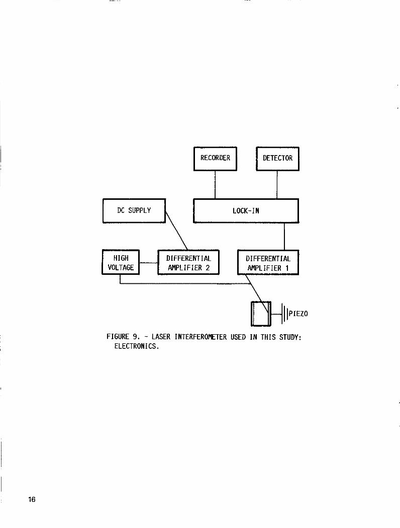
The electronic system (fig. 9) was assembled entirely from commercial parts. Differential amplifiers isolate the relatively high voltage necessary
7

to d r i v e the p i e z o e l e c t r i c t r a n s l a t o r s from t h e dc power supply and t h e l o c k - i n a m p l i f i e r . A t ransformer can be s u b s t i t u t e d for t h e d i f f e r e n t i a l a m p l i f i e r DA1, i . e . , t h e one t h a t t r a n s f e r s t h e o s c i l l a t i n g s i g n a l , t o enhance t h e s igna l - to -no ise r a t i o . The l o c k - i n ' s r e f e r e n c e o s c i l l a t o r a l s o s u p p l i e d t h e modulat ion f requency of 5000 Hz to t h e p i e z o e l e c t r i c t r a n s l a t o r s . E i t h e r t h e r e f l e c t o r or t h e o p t i c a l re fe rence f l a t can be v i b r a t e d ; however, i t t u r n e d o u t t o be p r e f e r a b l e t o v i b r a t e t h e r e f e r e n c e f l a t . a component a r i s e s from ac d e t e c t i o n w i t h t h e l o c k - i n a m p l i f i e r , which i s t h e s tandard method of d e t e c t i o n for smal l s i g n a l - t o - n o i s e r a t i o s .
The need f o r t h e v i b r a t i n g o f
The 5000 Hz o s c i l l a t i o n f requency was a r b i t r a r i l y chosen because o f i t s a u d i b i l i t y . t h e c r y s t a l . A 500 Hz f requency gave b e t t e r s igna l - to -no ise r a t i o s .
However, i t t u r n e d o u t t o be r a t h e r h i g h f o r t h e t i m e c o n s t a n t o f
The l a s e r i n t e r f e r o m e t e r ( f i g . 8 ) measures the changes o f d i s t a n c e between t h e o p t i c a l r e f e r e n c e f l a t and t h e r e f l e c t o r . Because of t he i n t e r p o s e d l e n s the i n t e r f e r e n c e p a t t e r n i n t e r c e p t e d on t h e screen n e x t to t h e l a s e r or i n the p lane o f t h e photodiode c o n s i s t s o f (Newton's) r i n g s . D is tance changes ( d i s - placements) can be determined from changes i n t h e r i n g r a d i i or , more accu- r a t e l y , from changes o f r i n g i n t e n s i t y a t say h a l f h e i g h t ( F i g . 4 ) reco rded p h o t o e l e c t r i c a l l y .
RESULTS
Figures 10 and 1 1 show photographs of t h e r i n g p a t t e r n s f o r two s l i g h t l y d i f f e r e n t p o s i t i o n s o f the r e f l e c t o r . F i g u r e 12 shows a r e c o r d e r t r a c e f o r a t i m e cons tan t o f f o u r seconds. I t was found t h a t t h e innermost f r i n g e o f f i g - u r e 10 moved by h a l f a f r i n g e when a dc p o t e n t i a l of 300 V was p u t on t h e p i e z o e l e c t r i c t r a n s l a t o r ( a tube ) . The n o i s e l e v e l on t h e c h a r t was 0.5 u n i t s , corresponding t o 0.7 V a p p l i e d t o t h e p i e z o e l e c t r i c t r a n s l a t o r . f r i n g e corresponds to approx ima te l y 1500 A of d isp lacement , a d i splacement sen- s i t i v i t y o f
S ince h a l f a
\I' = 1500(%) = 3.5 A ( fo r t i m e c o n s t a n t 4 sec)
= 2.0 A ( f o r t i m e c o n s t a n t 12.5 sec)
was c a l c u l a t e d . When t h e t i m e c o n s t a n t was s e t a t 12.5 sec on t h e l o c k - i n a m p l i f i e r , t h e corresponding \I' was about 2 A . Th is va lue i s about t w i c e t h a t o f B i n n i g ( r e f . 3 > , b u t should s t i l l be adequate f o r t h e purpose. I t would v e r y l i k e l y have been reduced by h a l f if t h e modu la t i on f requency had been 500 i n s t e a d o f 5000 Hz. stage o f t he program.
However, l a c k o f t i m e p reven ted f u r t h e r t e s t i n g a t t h a t
DISCUSSION AND CONCLUSION
I t seems c l e a r t h a t t h e main reason for a t t a i n i n g an accuracy and p r e c i - s i o n o f measurement on t h e l e v e l o f angstroms was t h e p i e z o e l e c t r i c p o s i t i o n - e r s , fo r the l a s e r was n o t s t a b i l i z e d and t h e o p t i c a l t a b l e was o f inadequate q u a l i t y . Tolansky had p a i d c o n s i d e r a b l y more a t t e n t i o n t o d e t a i l , b u t reached o n l y a s e n s i t i v i t y o f about 3.5 A . The o p t i c a l t a b l e c o u l d be improved by a
a

h e a v i e r t a b l e top . However, l a s e r s t a b i l i z a t i o n would p r o b a b l y be more impor- t a n t . The b e s t way of d o i n g t h i s would be t h e use o f two l a s e r f r e q u e n c i e s from t h e same l a s e r source i n a way s i m i l a r to Sommargren's method r e f e r r e d t o e a r l i e r . I n t e n s i t y v a r i a t i o n s a r e thus immed ia te l y compensated. Time d i d n o t p e r m i t c o n s t r u c t i o n o f a three-mode l a s e r system s i m i l a r t o t h a t o f Boersch ( r e f . 71, which was d i scussed . I t i s q u e s t i o n a b l e , however, whether an AFM even i n a vacuum c o u l d be made s t a b l e enough t o b e n e f i t from i t . On t h e o t h e r hand, t h e evanescent wave/ f luorescence system c o u l d be made much s i m p l e r t h a n o u r l a s e r i n t e r f e r o m e t e r and would be p o t e n t i a l l y more p r e c i s e . I t i s c u r - r e n t l y under s tudy .
I t i s wo r th r e p e a t i n g t h a t o p t i c a l m e t r o l o g y i s capab le o f angs t rom or subangstrom accuracy and p r e c i s i o n o n l y i n t h e a x i a l (2-1 d i r e c t i o n . h i g h l a t e r a l accuracy and p r e c i s i o n t h e v e r y f i n e s t y l u s , perhaps o f a tomic d imens ions , used i n t h e STM and AFM i s needed as a p robe.
To g e t
REFERENCES
1. Golovchenko, J.A., "The T u n n e l i n g Microscope: a New Look a t t h e Atomic World," Science, Vol. 232, No. 4746, Apr. 4, 1986, pp. 48-53.
2 . B i n n i g , G. and Rohrer, H . , "Scanning Tunne l i ng Mic roscopy , " IBM J o u r n a l o f Ressarch and Development, Vol. 30, No. 4, J u l y 1986, pp. 355-369.
3. B i n n i g , G., Quate, C.F., and Gerber, C., "Atomic Force Mic roscope, " P h y s i c a l Review L e t t e r s , Vol. 56, No. 9, Mar. 3, 1986, pp. 930-933.
4. McCle l land, G.M., E r landson, R . , and Chiang, S. , "Atomic Force Mic roscopy : General P r i n c i p l e s and a New I n p l e m e n t a t i o n , " Review o f P rog ress i n Q u a n t i t a t i v e N o n d e s t r u c t i e E v a l u a t i o n , Vol. 6B, Plenum Press , New York, 1987, pp. 1307-1314.
5. Tabor, D . and W i n t e r t o n , R.H.S. , "The D i r e c t Measurement o f Normal and Retarded Van Der Waals Forces , " Proceedings o f t h e Royal S o c i e t y o f London, S e r i e s A, Vol. 312, No. 1511, Sept. 30, 1969, pp. 435-450.
6. Horn, R.G. and I s r a e l a c h v i l i , J.N., " D i r e c t Measurement o f S t r u c t u r a l Forces Between Two Sur faces i n a Nonpolar L i q u i d , " J o u r n a l o f Chemical Phys i cs , Vol. 75, NO. 3, AUg. 1 , 1981, pp. 1400-1411.
7. Boersch, H . , E i c h l e r , H.J. , P f u n d s t e i n , M. , and Wiesemann, W . , "Measurement o f Length S h i f t s Down t o Angstrom w i t h a Three-Mode Laser , " Jou rna l o f Quantum E l e c t r o n i c s , Vol. QE-10, No. 6, June 1974, pp . 501-504.
8. Moss, G.E., M i l l e r , L.R., and Forward, R.L.. "Photon-No ise-L imi ted Laser Transducer f o r G r a v i t a t i o n a l Antenna," A p p l i e d O p t i c s , V o l . 10, No. 11, NOV. 1971, pp. 2495-2498.
9. L i u , L.S. and K l i n g e r , J.H., "Theory and A p p l i c a t i o n o f Laser I n t e r f e r o m e t e r Systems," I n t e r f e r o m e t r y , S P I E Vol. 192, G.W. Hopk ins , ed., S P I E , Be l l ingham, HA, 1979, pp. 17-26.
9
10. Sommargren, G.E., "Optical Heterodyne Profilometry," Applied Optics, Vol. 20, No. 4, Feb. 15, 1981, pp. 610-618.
1 1 . Tolansky, S . , Multiple Beam Interferometry of Surfaces and Films, Clarendon Press, Oxford, 1948.
12. Tolansky, S., An Introduction to Interferometry, Second Edition, John Wiley & Sons, New York, 1973, p. 169.
13. Born, M. and Wolf, E . , Principles o f Optics, Second Edition, MacMillan, New York, 1964.
14. Schaefer, C. and Gross, G., "Investigation on Total Reflection," Ann. Physik, Vol. 32, No. 3, June 2 , 1910, pp. 648-672.
15. Mirabella, F . M . Jr. and Harrick, N.J., Internal Reflection Spectroscopy: Review and Supplement, Harrick Scientific Corp., Ossining, NY, 1985.
16. Hirschfeld, T., "Total Reflection Fluorescence Spectroscopy," U . S . Patent 3,604,927, 1971.
17. Harrick, N.J. Internal Reflection Spectroscopy, John Wiley, New York, 1967.
18. Allain, C., Ausserre, D., and Rondelez, F. , "Direct Optical Observation of Interfacial Depletion Layers in Polymer Solutions," Physical Review Letters, Vol. 49, No. 23, Dec. 6, 1982, pp. 1694-1697.
19. Atherton, P. , "Micropositioning Using Piezoelectric Translators," Photonics Spectra, Vol. 21, No. 12, Dec. 1987, pp. 51-54.
10

LR 3- ‘L c
FIGURE 1. - LASER WITH COUPLED RESONATOR.
I I \
. 120 BEAHSPL I TTER
\ PIEZO- \ CYLI N D E R ~
n LASER
FIGURE 2. - MICHELSON INTERFEROMETER OF MOSS ET AL. C81.
11

\
LASER RADIATION
BEAMSPLITTER
REFERENCE FLAT-
FIGURE 3. - TOLANSKY'S SETUP FOR MULTIPLE- BEAM INTERFEROMETRY.
12
I
FIGURE 4. - VIEWING WITHIN A SHARP FRINGE GIVES A LARGE INTENSITY CHANGE dI FOR A SHALL STEP d t BETWEEN REFLECTORS,
13

REFLECTED WAVE
GAP / / INCIDENT WAVE
FIGURE 5 . - FRUSTRATION OF THE EVANESCENT WAVE (0i > 0 ~ ) .
PHOTONULTI PL IER
LENS OF HIGH APERTURE
/ FLUORESCEIN SOLUTION .
LASER BEAN
AFN CANT I LEVER
FIGURE 6. - EVANESCENT WAVE-EXCITED FLUORESCENCE AS AN ANGULAR D I SPLACENENT DETECTOR.
I 14

X
t Y SAMPLE
DEFLECT I ON SENSOR
XYZ TRANSLATOR n LEVER.
FIGURE 7. - ATOMIC FORCE MICROSCOPE (SCHEMATIC).
TREFLECTOR I BEAHSPL I TTER \
-I- APERTURE
I DETECTOR
FIGURE 8. - LASER INTERFEROMETER USED I N THIS STUDY: OPTICS.
15
DC SUPPLY ?
\
LOCK- IN
FIGURE 9. - LASER INTERFEROMETER USED IN THIS STUDY: ELECTRON I CS .
HIGH VOLTAGE
16
DIFFERENTIAL DIFFERENTIAL / AMPLIFIER 2 AMPLIFIER 1
t

OMGINAE PAGE IS OB POOR QUALITY
FIGURE 10. - INTERFERENCE RINGS OF THE LASER INTERFEROMETER (ORIGINAL POSITION OF REFLECTOR).
17

FIGURE 11. - INTERFERENCE RINGS OF THE LASER INTERFEROMETER (SLIGHT DISPLACEMENT OF REFLECTOR). THE CHANGE I N INTENSITY OF THE SIALL- EST RING AND THE CHANGE OF RADIUS OF THE NEXT ONE ARE CLEARLY OB- SERVABLE.
18

FIGURE 12. - RECORDER TRACE FOR A 7-VOLT CHANGE (X = 7 V I OF THE POTENTIAL ON THE PIEZO TRANSLATOR, NOTE THAT THE NOISE LEVEL I S ABOUT ONE TENTH O f THAT OR 0 . 7 VOLT, THE TINE CONSTANT WAS 4 SECONDS. THERE WAS A SLIGHT THERMAL
. DRIFT.
19

cw\sA ~ a m n a l Aeronaul8cs and Report Documentation Page 1. Report No.
NASA TM-100299
Space Administration
2. Government Accession No.
7 . Key Words (Suggested by Author@))
Metrology Interferometry
7. Author(s)
James L. Lauer and Phillip 6 . Abel
18. Distribution Statement
Unclassified - Unlimited Subject Category 35
9. Performing Organization Name and Address
National Aeronautics and Space Administration Lewis Research Center Cleveland, Ohio 44135-3191
National Aeronautics and Space Administration Washington, D.C. 20546-0001
12. Sponsoring Agency Name and Address
9. Security Classif. (of this report)
3. Recipient's Catalog No.
21. No of pages 22. Price' , 20. Security Classif. (of this page)
5. Rewrt Date
Unc 1 ass i f i ed
6. Performing Organization Code
Unclassified 20 A02
8. Performing Organization Report No.
E-3945 10. Work Unit No.
505-63-2A 11. Contract or Grant No.
13. Type of Report and Period Covered
Technical Memorandum 14. Sponsoring Agency Code
15. Supplementary Notes
Prepared f o r t h e 3 4 t h I n t e r n a t i o n a l I n s t r u m e n t a t i o n Symposium sponsored by t h e I n s t r u m e n t S o c i e t y o f America, Albuquerque, New Mexico, May 2-5, 1988. James L. Lauer , Dept . o f Mechanical E n g i n e e r i n g , A e r o n a u t i c a l E n g i n e e r i n g and Mechanics, Rensselaer P o l y t e c h n i c I n s t i t u t e , Troy, New York 12180-3590; a l s o Summer F a c u l t y F e l l o w a t NASA Lewis Research C e n t e r i n 1987. Research C e n t e r .
P h i l l i p 8 . A b e l , NASA Lewis
16. Abstract
The recent development of the scanning electron tunneling microscope and the atomic force microscope requires absolute standards for measurements in the ang- strom and subangstrom range. Optical interferometry with lasers and multiple mode laser resonances can provide absolute measurements as the laser wavelengths are very accurately known. A key feature of such measurements is the use of piezoelectric crystals as translators o f the highest accuracy f o r very small dis- tances. However, the dimensional changes of these crystals resulting from elec- trical potential changes depend on many variables, among them the method of mounting, so that accurate calibrations are necessary. Starting from advances in optical metrology made by physicists trying to find gravity waves, advances which led to measurements down to 10-5 A , the author designed and built a much simpler system for the angstrom range. The major limiting factors were mechanical vibra- tions, air currents, thermal changes and laser instabilities.