development of a computer software for hydraulic design...
TRANSCRIPT

i
DEVELOPMENT OF A COMPUTER SOFTWARE FOR HYDRAULIC DESIGN
OF SMALL HYDROPOWER FACILITY
A THESIS SUBMITTED TO
THE GRADUATE SCHOOL OF NATURAL AND APPLIED SCIENCES
OF
MIDDLE EAST TECHNICAL UNIVERSITY
BY
EMİR ALİMOĞLU
IN PARTIAL FULFILLMENT OF THE REQUIREMENTS
FOR
THE DEGREE OF MASTER OF SCIENCE
IN
CIVIL ENGINEERING
SEPTEMBER 2012

ii
Approval of the thesis:
DEVELOPMENT OF A COMPUTER SOFTWARE FOR HYDRAULIC
DESIGN OF SMALL HYDROPOWER FACILITY
submitted by EMİR ALİMOĞLU in partial fulfillment of the requirements for the
degree of Master of Science in Civil Engineering Department, Middle East
Technical University by,
Prof. Dr. Canan Özgen
Dean, Graduate School of Natural and Applied Sciences ____________
Prof. Dr. Güney Özcebe
Head of Department, Civil Engineering ____________
Prof. Dr. A. Melih Yanmaz
Supervisor, Civil Engineering Dept., METU ____________
Assoc. Prof. Dr. Zafer Bozkuş
Co-Supervisor, Civil Engineering Dept., METU ____________
Examining Committee Members
Prof. Dr. Doğan Altınbilek
Civil Engineering Dept., METU ____________
Prof. Dr. A. Melih Yanmaz
Supervisor, Civil Engineering Dept., METU ____________
Assoc. Prof. Dr. Zafer Bozkuş
Co-Supervisor, Civil Engineering Dept., METU ____________
Assoc. Prof. Dr. Nuri Merzi
Civil Engineering Dept., METU ____________
Dr. Kamil Hakan Turan
Civil Engineer, Mimpaş A.Ş ____________
Date: 07 September 2012

iii
I hereby declare that all information in this document has been obtained and
presented in accordance with academic rules and ethical conduct. I also declare
that, as required by these rules and conduct, I have fully cited and referenced
all material and results that are not original to this work.
Name, Last name : Emir ALİMOĞLU
Signature :

iv
ABSTRACT
DEVELOPMENT OF A COMPUTER SOFTWARE FOR HYDRAULIC DESIGN
OF SMALL HYDROPOWER FACILITY
Alimoğlu, Emir
M.Sc., Department of Civil Engineering
Supervisor: Prof. Dr. A. Melih Yanmaz
Co-Supervisor: Assoc. Prof. Dr. Zafer Bozkuş
September 2012, 183 pages
Run-of-river type hydroelectrical power plants are the facilities that use only the
available flow on the river without storing it to generate electrical energy. These kind
of facilities are composed of structural components such as diversion weir,
conveyance line, forebay, penstock and power house. In this thesis, a computer
program called “MiniHEPP Hydraulic Design” is developed in order to perform the
hydraulic design of run-of-river type hydropower plants. This program which runs
under the Windows operating system, was developed in C# programming language.
MiniHEPP Hydraulic Design is capable of performing hydraulic design of structural
components of diversion weir with sidewise intake and overflow spillway, canal,
forebay, and penstock. In addition, it can determine the optimum design discharge
and penstock diameter of this type of hydropower plants.
Keywords: Hydroelectrical Energy, Run-of-river Type Hydropower Plants,
Computer Aided Design

v
ÖZ
KÜÇÜK HİDROELEKTRİK SANTRALLARIN HİDROLİK TASARIMI İÇİN
BİLGİSAYAR YAZILIMI GELİŞTİRİLMESİ
Alimoğlu, Emir
Yüksek Lisans, İnşaat Mühendisliği Bölümü
Tez Yöneticisi: Prof. Dr. A. Melih Yanmaz
Ortak Tez Yöneticisi: Doç. Dr. Zafer Bozkuş
Eylül 2012, 183 sayfa
Nehir tipi hidroelektrik santrallar, depolaması olmayan, sadece nehirdeki mevcut
akımı kullanarak elektrik enerjisi üretilen tesislerdir. Bu tip sistemlerde, regülatör,
isale hattı, yükleme havuzu, cebri boru ve santral binası yapı elemanları
bulunmaktadır. Bu tezde, nehir tipi hidroelektrik santralların hidrolik tasarımı için
“MiniHEPP Hydraulic Design” adında bir bilgisayar yazılımı geliştirilmiştir. C#
programlama dilinde geliştirilen bu program, Windows işletim sistemi altında
çalışabilmektedir. MiniHEPP Hydraulic Design, yandan alışlı dolu gövdeli
regülatör, iletim kanalı, yükleme havuzu ve cebri boru yapı elemanlarının hidrolik
tasarımını yapabilmektedir. Buna ek olarak, nehir tipi santral sisteminin optimum
tasarım debisini ve cebri boru çapını da belirleyebilmektedir.
Anahtar Kelimeler: Hidroelektrik Enerji, Nehir Tipi Hidroelektrik Santrallar,
Bilgisayar Destekli Tasarım

vi
To my dear family,

vii
ACKNOWLEDGEMENTS
The author wishes to express his appreciation to his supervisors Prof. Dr. A. Melih
Yanmaz and Assoc. Prof. Dr. Zafer Bozkuş for their endless contribution and
guidance throughout this study.
The author would like to thank his brother and colleague Murat Alimoğlu for his
support and guidance throughout the author’s whole educational, professional and
personal life. The remaining family members, Şakir Alimoğlu, Naime Alimoğlu
and Aktuğ Alimoğlu are also acknowledged especially for their love, support, and
understanding.

viii
TABLE OF CONTENTS
ABSTRACT .............................................................................................................. iv
ÖZ........ ...................................................................................................................... v
ACKNOWLEDGEMENTS ..................................................................................... vii
TABLE OF CONTENTS ........................................................................................ viii
LIST OF TABLES ................................................................................................... xii
LIST OF FIGURES ................................................................................................ xiii
LIST OF SYMBOLS AND ABBREVIATIONS .................................................... xv
CHAPTERS
1. INTRODUCTION .......................................................................................... 1
2. HYDROELECTRIC POWER PLANTS ....................................................... 4
2.1 Components of Run-of-river Plants ....................................................... 6
2.1.1 Diversion Weirs ............................................................................. 7
2.1.1.1 Intake .......................................................................................... 8
2.1.1.2 Spillway ..................................................................................... 9
2.1.1.3 Stilling Basin .............................................................................. 9
2.1.1.4 Sluiceway ................................................................................. 10
2.1.1.5 Riprap ....................................................................................... 11
2.1.1.6 Fish Passage ............................................................................. 11

ix
2.1.2 Conveyance Line .......................................................................... 11
2.1.3 Forebay ......................................................................................... 13
2.1.4 Penstock ....................................................................................... 13
2.1.4.1 Determination of Penstock Route ............................................ 14
2.1.4.2 Number of Penstocks and Branches ......................................... 14
2.1.4.3 Support of Penstock ................................................................. 16
2.1.5 Power Plant .................................................................................. 16
3. HYDRAULIC DESIGN OF A SMALL HYDROPOWER FACILITY ...... 18
3.1 Determination of Flow-Duration Curve and Flood Discharges ........... 18
3.1.1 Determination of Flow-Duration Curve ....................................... 19
3.1.2 Determination of Flood Discharges and Water Surface Profile... 19
3.2 Determination of Optimum Design Discharge .................................... 20
3.3 Determination of Optimum Penstock Diameter ................................... 23
3.3.1 Water Hammer ............................................................................. 24
3.3.2 Determination of Penstock Wall Thickness ................................. 25
3.3.3 Penstock Diameter Optimization ................................................. 26
3.4 Design of Forebay and Canal ............................................................... 27
3.5 Design of Diversion Weir .................................................................... 32
3.5.1 Design of Intake ........................................................................... 33
3.5.2 Design of Spillway and Sluiceway .............................................. 42
3.5.3 Design of Energy Dissipators....................................................... 45

x
4. DEVELOPMENT OF COMPUTER SOFTWARE ..................................... 48
4.1 Algorithms of the Program .................................................................. 49
4.1.1 General Flow of the Program ....................................................... 49
4.1.2 Algorithm for the Determination of Optimum Design Discharge
and Optimum Penstock Diameter ................................................................ 50
4.1.3 Program Module for Penstock Design ......................................... 53
4.1.4 Program Module for Forebay and Canal Design ......................... 55
4.1.5 Program Module for Design of Diversion Weir .......................... 55
4.1.5.1 Algorithm for Design of Intake ................................................ 56
4.1.5.2 Program Module for the Design of Energy Dissipator ............ 58
4.2 Interface of the Program....................................................................... 61
5. APPLICATION ............................................................................................ 62
5.1 Characteristics of the System and Input Data ...................................... 62
5.1.1 Hydrological Data ........................................................................ 62
5.1.2 Penstock Inputs ............................................................................ 64
5.1.3 Canal and Forebay Inputs............................................................. 65
5.1.4 Intake Inputs ................................................................................. 65
5.1.5 Spillway, Sluiceway and Energy Dissipator Inputs ..................... 65
5.1.6 Power House and General System Inputs .................................... 66
5.2 Calculations and Outputs ..................................................................... 66
5.3 Summary and Discussion of Outputs ................................................... 70

xi
6. CONCLUSIONS AND RECOMMENDATIONS ....................................... 72
6.1 Summary and Conclusions ................................................................... 72
6.2 Recommendations for Further Development ....................................... 73
REFERENCES ......................................................................................................... 74
APPENDICIES
A. USER-MANUAL FOR MINIHEPP HYDRAULIC DESIGN .................... 76
A.1 Main Window of MiniHEPP Hydraulic Design .................................. 76
A.2 Menu Items .......................................................................................... 77
A.2.1 File Menu Item ................................................................................... 77
A.2.2 View Menu Item................................................................................. 78
A.3 Input Pages ........................................................................................... 80
A.4 Tips for User ........................................................................................ 80
B. SOURCE CODE OF MINIHEPP HYDRAULIC DESIGN ........................ 82

xii
LIST OF TABLES
TABLES
Table 2.1 Recommended side slopes for unlined canals (Chow, 1959) ................... 12
Table 3.1 Fall velocities for quartz sand (Breuser and Raudviki, 1991) ................... 39
Table 5.1 Flood discharges and water surface elevations at riprap section .............. 64
Table 5.2 Outputs of execution ................................................................................. 69
Table 5.3 Comparison of results ............................................................................... 70

xiii
LIST OF FIGURES
FIGURES
Figure 2.1 Definition sketch for a typical pumped-storage plant ................................ 5
Figure 2.2 Definition sketch for a typical run-of-river plant ...................................... 6
Figure 2.3 Typical plan view of a diversion weir with a sidewise intake (Yanmaz,
2006) ................................................................................................................ 8
Figure 2.4 Typical cross-section of an intake structure (Yanmaz, 2006) ................... 8
Figure 2.5 Longitudinal profile of stilling basin and spillway (Yanmaz, 2006) ....... 10
Figure 2.6 Longitudinal profile of sluiceway (Yanmaz, 2006) ................................. 11
Figure 2.7 Types of penstock branches (Yıldız, 1992) ............................................. 15
Figure 3.1 Plan view and cross section of a forebay ................................................. 28
Figure 3.2 Submergence depth .................................................................................. 29
Figure 3.3 Plan and cross sectional view of intake (Yanmaz, 2006) ........................ 35
Figure 3.4 Cross-sectional view of spillway axis (Yanmaz, 2006)........................... 43
Figure 3.5 Flow over the spillway and through the sluiceway (Yanmaz, 2006) ...... 44
Figure 4.1 General flowchart of the software ........................................................... 50
Figure 4.2 Flowchart describing design discharge and penstock diameter
optimization ................................................................................................... 53
Figure 4.3 Flowchart describing determination of penstock wall thickness ............. 54
Figure 4.4 Flowchart describing the design of intake ............................................... 57

xiv
Figure 4.5 Flowchart describing the determination of sluiceway and spillway
discharges ...................................................................................................... 59
Figure 4.6 Flowchart describing the design of energy dissipators ............................ 60
Figure 5.1 Flow duration curve ................................................................................. 63
Figure 5.2 Power duration curve ............................................................................... 63
Figure 5.3 Determination of optimum discharge ...................................................... 67
Figure 5.4 Determination of optimum penstock diameter ........................................ 67
Figure 5.5 Determination of optimum installed capacity .......................................... 68
Figure A.1 Main window of MiniHEPP Hydraulic Design ...................................... 76
Figure A.2 File menu items ....................................................................................... 78
Figure A.3 View menu items .................................................................................... 79
Figure A.4 A typical output window of MiniHEPP Hydraulic Design .................... 79
Figure A.5 A typical input page of MiniHEPP Hydraulic Design ............................ 81

xv
LIST OF SYMBOLS AND ABBREVIATIONS
A : Area of flow
Ag : Gross area of flow
An : Net area of flow
aw : Wave speed of water hammer wave
a : A coefficient as a function of d
b : Width of canal
Bfb : Width of forebay
Btr : Width of the thrashrack in front of the intake of forebay
Bsn : Net width at the entrance of intake
Bs : Width of settling basin
B3n : Net width at the entrance of canal
Cc : Contraction coefficient
Cic : Cost of installed capacity
Cicu : Unit cost of installed capacity
Cp : Cost of penstock
Cpu : Unit cost of penstock
Com : Overall modified discharge coefficient
Ct : Head loss coefficient due to transition
Ce
: Cost of energy loss
CT : Total cost of penstock
C
: Discharge coefficient
c1 : Dimensionless parameter that describes the support of penstock
CRF : Capital recovery factor
D : Penstock diameter

xvi
DA : Diameter of aeration pipe
Dmax : Maximum diameter of particles to be settled in the settling basin
Dm : Median size of a particle
dsl : Depth of sluiceway gates
d : Water depth in canal
E : Modulus of elasticity
Ef : Firm energy
Es : Secondary energy
Et : Total energy
E3s
: Energy level at the downstream of the spillway
E3sl : Energy level at the downstream of the sluiceway
Eu : Upstream energy level
e : efficiency
eh : Efficiency of transformer
et : Efficiency of turbine
eg : Efficiency of generator
f : Friction factor through pipe
fc
: Freeboard of canal
Fr : Froude number
g : Gravitational acceleration
G : Weight of penstock
Hg : Gross head
Hn : Net head
H : Water depth over the spillway
H0 : Spillway design head
Hs : Steady state head
h : Water depth at the upstream of the spillway
ha : Velocity head at the upstream of the spillway
hfb : Difference between maximum and minimum water levels in
forebay
he : Total height of in front of intake

xvii
hd : Difference between upstream and downstream energy gradeline
elevations
hf : Friction loss through the penstock
hl : Total head loss through the penstock
hm : Total minor losses through the penstock
K : Orifice coefficient
Kcd : Bottom elevation at the canal exit
Kcu : Bottom elevation at the canal entrance
Kab : Contraction coefficients due to abutments
Kd : Water surface elevation at riprap section
K5 : Upstream water surface elevation for flood discharge Q5
K10 : Upstream water surface elevation for flood discharge Q10
K25 : Upstream water surface elevation for flood discharge Q25
K50 : Upstream water surface elevation for flood discharge Q50
K100 : Upstream water surface elevation for flood discharge Q100
Kd5 : Water surface elevation at riprap section for flood discharge Q5
Kd10 : Water surface elevation at riprap section for flood discharge Q10
Kd25 : Water surface elevation at riprap section for flood discharge Q25
Kd50 : Water surface elevation at riprap section for flood discharge Q50
Kd100 : Water surface elevation at riprap section for flood discharge Q100
Km : Minor loss coefficient
Kp : Contraction coefficient due to piers
Kpi : Penstock invert elevation
Kr : Bottom elevation at riprap section
Ks : Crest elevation of spillway
Ksf : Crest elevation of side spillway in the forebay
Ksl : Crest elevation of sluiceway gates
Kst : Thalweg elevation at the entrance of intake
Kw : Water surface elevation at a section of intake
Kwi : Water surface elevation in front of intake
L : Length of penstock

xviii
Lspill : Length of spillway
Lsspill : Length of side spillway of forebay
Le : Width of sluiceway gates
Lc : Length of canal
LT : Total length of valley at spillway axis
Leff : Effective length of spillway
Lfb : Length of forebay
m : Horizontal inclination of canal sides
ME : Marginal energy
MaxWL : Maximum water level in forebay
MinWL : Minimum water level in forebay
NWL : Normal water level in forebay
n : Manning’s roughness coefficient
nbr : Number of bridge piers
np : number of piers at the entrance of canal
npi : number of piers at the entrance of intake
ns : Manning’s roughness coefficient in settling basin
nsl : number of sluiceway gates
P : Height of spillway
Pfirm : Firm energy unit price
Pp : Power generated by the plant
Psec : Secondary energy unit price
Q : Discharge
Qd : Design discharge
Q5 : Flood discharge with a return period of 5 years
Q10 : Flood discharge with a return period of 10 years
Q25 : Flood discharge with a return period of 25 years
Q50 : Flood discharge with a return period of 50 years
Q100 : Flood discharge with a return period of 100 years
Qs : Discharge over spillway
Qsl : Discharge through sluiceway

xix
Qeq : Equivalent discharge
Qtur : Design discharge of a single turbine
R : Hydraulic radius
Rb : Radius of bend
s : Degree of submergence
str : Maximum spacing between the rackbars at the entrance of intake
S0 : Canal bottom slope
S0s : Bottom slope of settling basin
: Average friction slope
T : Valve closure time
Tcr : Critical closure time
t : Wall thickness of penstock
tbp : Thickness of bridge piers
tp : Thickness of piers at the entrance of canal
tpi : Thickness of piers at the entrance of intake
tpf : Thickness of piers at the entrance of intake of forebay
tsl : Thickness of piers between the sluiceway gates
ttr : Thickness of rackbars at the entrance of intake
u : Average flow velocity at a section
V : Velocity
Vmax : Maximum allowed velocity in settling basin
Vfb : Volume of forebay
Vf : Final velocity
Vi : Initial velocity
Va : Velocity in front of the thrashrack at the forebay intake
Wf : Fall velocity of a particle
y : Water depth at a section
∆ : Sill height at the end of the stilling basin
∆a : Upward step height at the entrance of forebay intake
∆b : Angle of penstock bends

xx
∆s : End sill height at the stilling basin of spillway section
∆sl : End sill height at the stilling basin of sluiceway section
∆sd : Downward step at the settling basin entrance
∆su : Height of upward sill at the end of stilling basin
∆u : Height of upward sill at the end entrance of intake
∆E3s : Head loss due to the hydraulic jump at the spillway downstream
∆E3sl : Head loss due to the hydraulic jump at the sluiceway downstream
∆t : Equal time interval on flow-duration curve
∆Q : Discharge difference between two consecutive time intervals
∆Ht1 : Minor loss due to transition at section-2 of intake
∆Ht2 : Minor loss due to transition at section-4 of intake
∆H : Head increase due to water hammer
∆Htr : Minor loss due to trashracks
∆Hi : Minor loss above the upward sill, ∆u
∆Hg1 : Minor loss due to gates
∆He : Minor loss due to the upward sill, ∆su
∆Hei : Minor loss due to the submerged curtain wall at the entrance of
intake
∆Hes : Minor loss due to the downward sill, ∆sd
∆Hs : Friction loss through settling basin
σt : Allowable tensile strength of pipe material
γ : Specific weight of water
γp : Specific weight of pipe material
ρ : Density of water

1
CHAPTER 1
1. INTRODUCTION
Hydroelectric power is simply generated by releasing water with a certain
discharge from a certain elevation, to a level with a relatively low elevation where
a water turbine is operated. Hydroelectric power is considered one of the most
important kinds of energy production because of the renewable and sustainable
nature of hydroelectric energy generation. In the recent years, hydropower projects
have gained significant importance in Turkey as a result of the increasing demand
in energy consumption.
The design of hydroelectric power systems has difficulties since the systems
include different components which have various hydraulic and structural
requirements and functions. In addition, each project has multi-disciplinary
engineering aspects including safety and economy. Hydroelectric power systems
also have environmental and social issues associated with them which have
significant importance on the final design of the projects.
Hydraulic design of hydroelectric power systems requires the application of
various hydraulic concepts which are mostly calculation processes. The designer
must seek the optimum design of all structural components because of the
aforementioned reasons and the unique characteristics of each individual project.
Therefore, the numerical procedures are carried out in an iterative manner in order
to compare different design alternatives. The design is finalized by satisfying the

2
safety, economy and also environmental and social issues.
The design of such a system requires time and effort. The utilization of computer
softwares reduces the time required to perform complicated calculation processes
as well as decreases the calculation errors. Furthermore, it enables quick
comparison of several alternatives. Therefore, the aid of computer softwares is
inevitable.
Although design companies use different packages for the design of different
structural components, a computer program that includes the design of all
components is a very useful tool in order to simulate the interaction between the
parts of the hydroelectric power system. Development of a hydraulic design
software for a particular type of system using the worldwide and Turkish
specifications is of importance. Such a program enables a designer to perform
quick runs such that several alternatives can be compared to each other. A
computer program developed by Turan (2004), which performs optimum hydraulic
design of diversion weirs, is considered as a good example serving for this
purpose. The main aim of this study is to develop a computer software that
includes the design of the whole hydropower system for small scaled projects. A
user-friendly, visual computer program called MiniHEPP Hydraulic Design has
been developed for this purpose. MiniHEPP Hydraulic Design includes typical
hydraulic design of the main components of small scaled hydropower systems.
The scope of this study is to allow the user to design the whole system using a
single computer program in order to provide a better simulation of the interaction
between the parts of the system and to increase the efficiency of the design
engineer.
This study is divided into six chapters in the following way: In Chapter 1, the
general scope of this study is explained. Chapter 2 provides the general definitions
of hydroelectric power plants and the functions of the components of small scaled
hydroelectric power systems. In Chapter 3, the computational flow of the software
is explained in detail. Chapter 4 gives the algorithmic logic of the program

3
modules. A case study is given in Chapter 5. Lastly, in Chapter 6, the
recommendations and conclusions are provided. The user manual of MiniHEPP
Hydraulic Design can be found in Appendix A and the source code of MiniHEPP
Hydraulic Design is provided in Appendix B.

4
CHAPTER 2
2. HYDROELECTRIC POWER PLANTS
Hydroelectric power plant types can differ depending on the available water
resources and topographic conditions. Generally, hydroelectric power plants can
be characterized by the way they utilize the water and they may be divided into the
categories given below (Yanmaz, 2006).
a) Pumped-storage plant
A pumped-storage plant consists of a headwater pond, penstock, a tailwater
pond and a reversible pump-turbine unit. The water is pumped from the
tailwater pond to headwater pond during low-demand hours using surplus
power produced by a fuel-fired plant which has a relatively low cost. Then,
releasing water through a penstock from headwater pond to a hydro turbine
during peak hours to generate electricity (see Figure 2.1). The overall
efficiency for these types of power plants is about 70% due to mechanical and
electrical losses during the pumping and generating processes (Yanmaz, 2006).

5
Figure 2.1 Definition sketch for a typical pumped-storage plant
b) Storage Plants
The most important component of a storage plant is the reservoir that stores
water in order to regulate the natural flow in the river to create an increment in
firm flow and thus in firm energy generation. The adequate amount of stored
water is drawn from the reservoir and released through a penstock to a hydro
turbine in order to generate the required power. For storage plants, the main
factor affecting the power generated is the created head since the amount of
flow that is utilized is controlled. The head can be created by a high dam.
However, construction of a very high dam may be very expensive. In these
cases, an application of power tunnels is considered to carry the desired
amount of flow to a suitable location and release water to the power house.
Headwater Pond Penstock
Tailwater Pond Power House
Reversible
Pump-Turbine
Unit

6
c) Run-of-river Plant
Run-of-river plant usually uses the flow in the river rather than storing water.
Therefore, the energy production for these kinds of plants is dependent on the
amount of flow on the river whose path is changed with a diversion weir and
water guided into a conveyance line, such as a channel or tunnel. Generally,
the diverted flow is transmitted to a headwater pond called forebay and then
released to a hydro turbine by means of a pipeline called penstock to generate
power (Figure 2.2). Since the main scope of this study is run-of-river plants,
the components of this kind of systems are explained in detail in this chapter.
Figure 2.2 Definition sketch for a typical run-of-river plant
2.1 Components of Run-of-river Plants
The main components of run-of-river type of hydroelectric power plants are the
following:
Diversion Weir
Diversion
Weir Diversion
Canal Penstock
Forebay
Power House

7
Conveyance Line
Forebay
Penstock
Power Plant
2.1.1 Diversion Weirs
The main function of a diversion weis in run-of-river type of plants is to divert the
flow of river. Then, the sediment is settled in a settling basin constructed after the
intake structure to prevent the entrainment of particles to the system. After the
settling basin, the flow is transmitted to the conveyance line.
Diversion weirs are classified according to (Yanmaz, 2006):
a) Magnitude of Q100
i. Small diversion weir (Q100 < 100 m3/s)
ii. Medium diversion weir (100 ≤ Q100 ≤ 500 m3/s)
iii. Large diversion weir (Q100 > 500 m3/s)
b) Structural Design
i. Diversion weir with spillway
ii. Gated diversion weir
c) Orientation of Intake
i. Diversion weir with sidewise intake
ii. Diversion weir with frontal intake
iii. Diversion weir with drop intake
where Q100 is peak discharge corresponding to a 100 year return period. Among
these different types of diversion weirs, the most common design in Turkey is
diversion weirs with sidewise intake (Yanmaz, 2006). Therefore, the diversion
weirs of sidewise intake type is covered in this study. The plan view of a typical
diversion weir with a sidewise intake is given in Figure 2.3. The main components
of diversion weirs with sidewise intake are covered below.

8
Fig
ure
2.3
Typic
al p
lan v
iew
of
a div
ersi
on w
eir
wit
h a
sid
ewis
e in
take
(Yan
maz
, 2006)

8
2.1.1.1 Intake
The basic function of intakes is to safely withdraw water from the source, i.e the
river in our case. Different types of intake structures are used in practice. Figure 2.4
shows a longitudinal profile of a gate controlled intake.
Figure 2.4 Typical cross-section of an intake structure (Yanmaz, 2006)
An intake structure is composed of following components from upstream to
downstream:
i. The submerged curtain is the part of intake used for the prevention of the
entraintment of floating objects, such as ice, logs, etc., into the intake of
the system. The minimum height of a submerged curtain is about 50-60
cm from the top of the intake and the orientation is perpendicular to the
Bridge Submerged
Curtain
Gate
Upstream
Blanket
Drain Filter Settling
Basin
Flushing
Gate
Sill
Sheet
Piling
9
direction of the flow.
ii. The screens are the racks placed in front of the vertical gate at the
entrance of intake structure. The screens are utilized in order to prevent
the entrainment of floating objects or coarse sediment into the intake.
iii. A a settling basin is provided in order to capture the sediment with a
desired size depending on the characteristics of the system.
iv. A flushing facility is placed at the end of the settling basin in order to
release the captured sediment in the settling basin back to the river. For
self-cleaning purposes, the flushing facility should have an adequate
slope and a diameter with a minimum of 60 cm.
v. Before the entrance of the conveyance line, a transition is constructed in
order to connect the settling basin to the conveyance line.
2.1.1.2 Spillway
A spillway is an important component of diversion weirs. Its main function is to
raise water, divert the project discharge and transmit the remaining flow to the
stilling basin (energy-dissipating basin) which is located just downstream of the
spillway.
2.1.1.3 Stilling Basin
A stilling basin is constructed in order to dissipate the excessive energy of flow,
generally in the occurance of a flood event. By doing so, the riverbed is protected by
means of scour. The longitudinal profile of stilling basin and spillway is shown in
Figure 2.5.

10
Figure 2.5 Longitudinal profile of stilling basin and spillway (Yanmaz,
2006)
2.1.1.4 Sluiceway
A sluiceway is the component that prevents the deposition of the captured sediment
in front of the intake by flushing it downstream of the diversion weir. When the
deposited sediment reaches to a certain elevation, the vertical lift gates of sluiceway
are opened in order to release and guide the sediment downstream by flushing. The
longitudinal profile of a sluiceway is given in Figure 2.6.
Sheet piling
Riprap
Downstream
Sidewall
Drain Filter
Stilling
Basin
Cutoff
Upstream
Blanket
Spillway
Construction
Joints
Sill
Upstream
Sidewall

11
Figure 2.6 Longitudinal profile of sluiceway (Yanmaz, 2006)
2.1.1.5 Riprap
The riprap section is placed just the downstream of stilling basin. The stones are
placed in this section with an adequate thickness and length to protect the riverbed.
2.1.1.6 Fish Passage
The fish passage is composed of successive pools that provides a passage for the fish
to migrate along the river.
2.1.2 Conveyance Line
The conveyance line transports the desired amount of flow which has been diverted
from the river, from intake to forebay. There are various types of conveyance lines,
such as canals, tunnels, pipelines, etc. The governing factor for conveyance line type
Riprap
Upstream
Sidewall
Downstream
Sidewall
Stilling
Basin Cutoff
upstream
blanket
Sheet piling Construction joints
Sill
Bridge
Guiding
wall
Gate
Submerged
curtain

12
is economy and topographic conditions. Canals which usually have rectangular or
trapezoidal cross-sections are the most common type utilized in hydropower
systems. Therefore, in this study, canals are covered in detail.
In order to transport the design discharge from the intake to the forebay, the canal
must have sufficient hydraulic capacity. This hydraulic capacity depends on the
canal bed slope and canal cross-section. Since the governing factor for the canal bed
slope is the hydraulic losses for hydropower plants, the cross-section of the canal
must have adequate dimensions to satisfy hydraulic capacity by taking economy into
account. Canals can be lined or unlined. Unlined canals are designed to have
trapezoidal cross-sections with side slopes decided according to the material of
foundation. The recommended side slopes for unlined canals are given in Table 2.1.
Table 2.1 Recommended side slopes for unlined canals (Chow, 1959)
Material Side Slope (H : V)
Rock Nearly vertical
Muck and peat soils 1/4 : 1
Stiff clay or earth with concrete lining 1/2 : 1 to 1 : 1
Earth with stone lining or earth for large channels 1 : 1
Firm clay or earth for small ditches 1.5 : 1
Loose sandy earth 2 : 1
Sandy loam or porous clay 3 : 1
For lined trapezoidal open canals, 1V : 1.5H side slopes are recommended by United
States Bureau of Reclamation (USBR) and the Turkish State Hydraulic Works (DSİ)
by considering the stability of side inclination as well as the construction techniques
and equipment.
In order to prevent the overtopping of waves and fluctuations in water surface from

13
the sides, a freeboard, fc, which is the vertical distance between the top of the canal
and the water surface at design conditions is provided. Generally, freeboards vary
from less than 5% to greater than 30% of the depth of flow (Chow, 1959).
2.1.3 Forebay
The forebay is the structural component between the canal and penstock. The main
purposes of forebay are the following:
1. Uniform distribution of flow to the penstock
2. Provide a gentle flow
3. Prevent the entrainment of floating objects and sediment to the penstock
4. Provide the sufficient discharge for turbines
5. Prevent the air entrainment to the penstock
6. Absorb the upsurges in case of a load rejection event
The main components of forebay are summarized below:
a) Intake
The intake section of a forebay is located just upstream of the penstock. It
consists of a sluice gate, trashrack and aeration pipe.
b) Bottom Outlet
The bottom outlet is used for flushing of the sediment and the discharge of
water in the forebay.
c) Side spillway and Side spillway Chute
A side spillway is provided in a forebay in order to release the excessive
flow back to the river through side spillway chute in case of a load rejection
event while the turbines are operating at maximum capacity.
2.1.4 Penstock
A penstock is defined as a water conduit which carries pressurized flow between the
forebay and the turbine. Usually, penstocks are made of steel since internal pressure

14
is high.
2.1.4.1 Determination of Penstock Route
Penstock can be installed underground or on the ground surface. The governing
factor for the determination of penstock route is the geological conditions. The
penstock route must be on firm soil. If the geological conditions are unfavourable,
shafts or tunnel can be considered.
The penstock route must be as short as possible. The cost of penstock and head
losses, which decreases energy production, increase with penstock length. For the
same reason, the penstock route must be straight as much as possible in order to
avoid head losses at bends.
2.1.4.2 Number of Penstocks and Branches
As a general rule, utilization of a single penstock with branches depending on the
number of turbines in the power plant, is the most economic solution. Types of
branches are shown in Figure 2.7.
The design of penstock with branches rises the problem of hydraulic losses at these
branches which depends on the deflection angle. These losses can be reduced by
joining the branch to the main pipe with a deflection angle less than 90o. Therefore,
the deflection angle usually varies between 30o and 75
o. The hydraulic efficiency is
increases for smaller deflection angles. However, at angles less than 45o, the
reinforcing of branch outles becomes more difficult (USBR, 1977).

15
Figure 2.7 Types of penstock branches (Yıldız, 1992)
α α
α
α α
R
α
α
HEPP
HEPP HEPP
(c)
(d) (e)
HEPP HEPP
(a) (b)

16
2.1.4.3 Support of Penstock
A long pipe with a number of supports acts like a continuous beam except for the
expansion joints. Therefore, ring girders or stiffener rings used to limit the
deformation of shell at the supports. The shell is subjected to direct beam and hoop
stresses with loads transmitted to supports by shear. In addition, secondary bending
stresses occur in the pipe shell near the ring girder or anchor because of the restraint
imposed by a rigid ring girder or concrete anchor. In order to design the pipeline to
have sufficient resistance to bending and shear forces, the following methods may
be utilized (USBR, 1977):
a. Shell vaving sufficient stiffness.
b. Continuous embedment of part of periphery of the pipe
c. Support cradles or saddles
d. Stiffener rings that carries the load to concrete piers by means of support
columns
2.1.5 Power Plant
The power plant is the structure where the energy is generated. The power plant
contains the necessary electromechanic equipment for energy production, such as
turbines, generators, and transformers. The location of power plant is determined
according to (Yıldız, 1992):
1. The power plant should be on a firm soil or rock. In order to maintain this,
half-buried or buried power plants can be considered.
2. The length of penstock and head losses must be reduced as much as possible.
3. The excavation costs should be minimized by placing the power plant on a
large and plain location.
4. Should be close to a switchyard.

17
5. The tailwater canal should be connected to the river economically.
6. The transportation to power plant should be suitable.

18
CHAPTER 3
3. HYDRAULIC DESIGN OF A SMALL HYDROPOWER
FACILITY
The hydraulic design process of a small scaled run-of-river type hydroelectric power
plant is explained in this chapter. The design of such a system is relatively
complicated because of the number and interaction of different structural
components. Therefore, the calculations must be carried out step by step and in a
systematical manner. The general steps of computations can be summarized as
follows:
Determination of flow-duration curve and flood discharges
Determination of optimum design discharge
Determination of optimum penstock diameter
o Design of penstock
Design of forebay and canal
Design of diversion weir
o Intake
o Spillway
o Sluiceway
o Energy dissipators
3.1 Determination of Flow-Duration Curve and Flood Discharges
The design process of a hydropower system starts with hydrological analysis of the

19
basin. The estimation of water potential i.e. the available flow in the river to be
utilized in energy production is essential since the design of structural components is
directly affected with the available amount of water in the river. The effect of a
possible drought period needs to be considered in the economic analysis of the
system. The accuracy of the flow duration curve can be tested using a sensitivity
analysis. In addition, the flood discharges are also needed for the design of a
spillway to transmit the excessive discharge downstream safely.
3.1.1 Determination of Flow-Duration Curve
The flow-duration curve represents the discharges on the river according to their
occurance percentages. Since the available flow is one of the governing variables for
the design of the system, the accurate estimation of flow-duration curve is very
important.
In Turkey, State Hydraulic Works (DSI) and General Directorate of Electrical Power
Resources Survey and Development Administration (EIE) have constructed Stream
Gaging Stations (SGS) on rivers and collected data throughout the years. By the
hydrological analysis of the data of nearby stations the flow-duration curve i.e the
water potential of the river is determined. In addition to the flow-duration method,
sequential stream routing based on daily flow data can also be used in the
determination of the river potential. Such a hydrological analysis is not in the scope
of this study hence the flow duration curve is assumed to be determined in advance.
3.1.2 Determination of Flood Discharges and Water Surface Profile
After locating structural elements of the system, the flood discharges that may occur
on the river must be determined and especially the design of diversion weir must be
made accordingly. In addition, water surface profile of the river is also needed for
checking hydraulic performance of the diversion weir under various flow conditions
having different return periods. In Turkish practice, return periods ranging between
2 to 100 years are used (Yanmaz, 2006). Therefore, Q5, Q10, Q25, Q50 and Q100 flood
discharges are obtained by the hydrological analysis of the basin and the

20
corresponding water surface profile can be obtained. The determination of flood
discharges and water surface profile are also not covered in this thesis.
3.2 Determination of Optimum Design Discharge
The determination of optimum design discharge is based on comparison of net
benefits of different alternatives. For each design discharge alternative on the flow-
duration curve, the costs of penstock and installed capacity, the energy production
and corresponding benefits are calculated and the net benefits of aforementioned
alternatives are compared. The optimum design discharge is decided based on the
maximum net benefit. This process is explained in this subsection.
Step 1: In order to calculate generated power and corresponding energy
generation, there is a need for an approximate penstock diameter since the
significant part of head losses occurs as the frictional losses through
penstock. In order to determine these initial penstock diameters for each
design discharge alternative the following velocity, V, can be used (Yıldız,
1992):
√ ( .1)
where, V is in m/s, Hg is the gross head of the power plant (m) which is
defined as the vertical distance between the water surface of forebay and the
water surface of tailwater downstream of the turbines. For each discharge on
the flow-duration curve, a corresponding penstock diameter is obtained by
satisfying the the velocity obtained in Equation (3.1).
Step 2: After determination of penstock diameters, corresponding wall
thickness of each penstock diameter is obtained. The process for
determination of wall thickness of penstock is explained in Section 3.3.1.
Step 3: In this step, the flow-duration curve is converted into power-duration
21
curve. Hydroelectric power generated by a plant can be expressed as:
( .2)
where, Pp is the power generated by the plant (Watts), Hn is the net head
(m), γ is the specific weight of water (N/m3) and e is the total efficiency
which is equal to e = eheget where eh is the efficiency of transformer, eg is the
efficiency of generator, and et is the efficiency of turbine.
The hydraulic losses occured through the penstock is the summation of
frictional losses, hf, and minor losses, hm, which is caused by trashracks,
bends, transitions, etc. The net head, Hn, is calculated by subtracting the
frictional head loss, hf, and total minor losses, hm, through the penstock from
gross head, Hg.
( . )
( . )
( . )
where, f is the friction factor through penstock, L is the length of penstock, D
is the diameter of penstock, Q is the discharge and is the minor loss
coefficient for a section concerned. For each value of Q on flow-duration
curve, the corresponding installed capacity is calculated by using Equations
(3.2), (3.3), (3.4) and (3.5). In other words, the power generated for each of
the occurence percentage is determined and power-duration curve is
obtained.

22
Step 4: The energy generation for each alternative is calculated by means of
firm energy, Ef, secondary energy, Es and total energy, Et. For the sake of
simplicity, the flow duration curve is divided into equal time intervals, ∆t,
which corresponds to a total of 8760 hours. In order to calculate the marginal
energy generation between these equal time intervals, an equivalent
discharge, Qeq is computed to represent the average discharge as
Qeq = duration (%) * ∆Q, where ∆Q is the discharge difference between two
consecutive time intervals. Then, marginal energy produced between time
intervals, ME, is expressed as:
( . )
Firm energy generation, Ef, is taken as the energy production which
corresponds to the 95% occurence on the power-duration curve. The
remaining energy generation is taken as secondary energy generation, Es.
Step 5: The costs of penstock and installed capacity are calculated. The
weight of penstock for circular cross-section is:
( . )
where, γp : specific weight of pipe material (kg/m3);
D : penstock diameter (m);
L : penstock length (m);
t : penstock wall thickness (m).
The cost of penstock, Cp for a yearly basis is calculated by:
( . )
where, Cpu is the unit cost of penstock ($/kg) and CRF is the capital recovery

23
factor. Similarly, the cost of installed capacity, Cic is obtained by:
( .9)
where, Cicu is the unit cost of installed capacity ($/MW) and Pp is the
installed capacity (MW).
Step 6: After determination of the costs of penstock and installed capacity,
the total cost is obtained by adding these two values. In addition, the values
of firm and secondary energy generations are multiplied by their
corresponding energy benefits and by doing so the total energy benefit is
obtained. In order to determine the net benefit for each alternative discharge
value, the total cost is subtracted from its corresponding energy benefit.
Step 7: Finally, the candidate discharge value on flow duration curve which
gives the maximum net benefit after following the above steps is selected as
the design discharge.
3.3 Determination of Optimum Penstock Diameter
The optimum penstock diameter is decided according to the design discharge
determined as explained in Section 3.2. The main reason to select an optimum
penstock diameter is that the frictional head loss is reduced with the incrementation
of penstock diameter for a constant discharge hence the energy generation and
energy benefit are increased.
In order to obtain an accurate optimum penstock diameter, the design of penstock is
also made simultaneously by means of the determination of wall thickness by
considering the water hammer effects. The calculation of wall thickness and the
concept of water hammer are explained in the following subsections.

24
3.3.1 Water Hammer
A sudden change of the rate of flow due to opening or closing valves creates a
pressure wave of high magnitude. Pressure wave travels back and forth in the pipe
until it vanishes due to friction or damped out. This pressure changes in the pipe, can
be several times larger than the steady state pressures, therefore the design of such
pipeline must include the consideration of water hammer phenomenon.
The speed of pressure wave depends on the elasticity of water, pipe dimensions and
the Young’s modulus of elasticity of pipe material. Wave speed, aw, is expressed as
(Wylie et al., 1993):
√
( ) (
)
( .10)
where, K : bulk modulus of water;
ρ : density of water;
E : elasticity modulus of pipe material;
D : pipe diameter;
t : wall thickness of the pipe;
c1 : a dimensionless parameter that describes the effect of pipe anchor on the
wave speed. In case of pipes anchored with expansion joints throughout, this
parameter can be taken as unity.
The pressure wave, starts to travel upstream from valve with speed aw, immeadiately
after the closure of valve. The total time for the pressure wave to travel to upstream
end of a pipe with a length of L and return to the downstream end of pipe which is
called critical time is expressed as:

25
( .11)
where, Tcr is the critical time and L is the pipe length. A valve movement that takes
place in less than the critical time is called rapid valve closure. The maximum
change in head for such a case is calculated by (Wylie et al., 1993):
(
) ( ) ( .12)
where, ∆H is the change in head, Vf is the final velocity in the pipe in the end of
valve movement and Vi is the initial velocity in the pipe at the beginning of valve
movement. For cases that the valve closure time is greater than critical time, the
head rise due to water hammer is calculated by:
(
) ( ) ( .1 )
where, T is the valve closure time.
3.3.2 Determination of Penstock Wall Thickness
The penstock wall thickness, t, mainly depends on the maximum tensile strength of
pipe material, σt, pipe diameter, D, and the operating pressure. However, in case of
water hammer events the pressure on the penstock is increased dramatically, hence
the wall thickness must be selected by taking into account the head increase on the
penstock due to water hammer. The wall thickness of penstock is calculated by:
( )
( .1 )
where, t : wall thickness of penstock;
γ : specific weight of water;

26
∆H : head increase due to water hammer;
Hs : steady state head;
D : penstock diameter;
σt : tensile strength.
The pipe must be appropriately rigid in order to manage deformations in the field
sufficiently. Therefore, ASME suggests a minimum wall thickness in mm that is
equal to the 2.5 times of the pipe diameter in meters plus 1.2 mm (ESHA, 2004).
For a certain penstock diameter, the speed of pressure wave and head rise due to
water hammer are calculated by using Equations (3.10), (3.11), (3.12) and (3.13). If
the tensile strength of penstock requires greater wall thickness, then the process is
repeated by increasing wall thickness until Equation (3.14) is satisfied.
Generally, penstocks are made of steel hence subjected to corrosion. Therefore, after
the wall thickness of penstock determined with the above procedure, it is increased
by additional 2 mm to provide safety.
3.3.3 Penstock Diameter Optimization
Following the determination of design discharge, the optimum penstock diameter is
obtained by comparing various diameter alternatives. For each alternative, the cost
of penstock, Cp is calculated by using Equation (3.8). Then, the total hydraulic
losses in the penstock, hl, is calculated by summing the frictional head loss and
minor head losses obtained by using Equations (3.3) and (3.4). By putting the total
hydraulic loss, hl, instead of Hn in Equation (3.6), the loss in energy generation of the
plant is obtained. The cost of energy loss, Ce is obtained by multiplying the cost of
energy benefit with the loss in energy generation. Total cost for each individual
diameter candidate, CT is calculated with the summation of Cp and Ce. The diameter
alternative with the minimum CT value is selected as the optimum penstock
diameter.

27
3.4 Design of Forebay and Canal
The design of forebay and canal is handled simultaneously in this study since the
dimensions and locations of these two components affect the design of each other
significantly. The plan and cross section of a typical forebay is given in Figure 3.1.
The best hydraulic section approach is utilized to determine the dimensions of the
canal which has a trapezoidal cross-section with side slopes m in the present study.
The relationship between the canal bottom width, b and water depth in the canal, d is
given as:
(√ ) ( .1 )
Fluctuations may occur on the water surface due to winds or some other
disturbances. A freeboard which is the height between the water surface and the top
elevation of the canal is provided to handle these fluctuations. An emprical equation
is proposed by USBR for the determination of freeboard, fc, as:
( ) ( .1 )
where, d is the water depth in the canal.
After obtaining the dimensions of canal, the water depth in the canal that
corresponds to the design discharge is computed by Manning’s Equation. The
obtained water surface elevation at this depth also corresponds to the normal water
level, NWL, in the forebay.
The next step in the design of forebay is the determination of minimum water level,
MinWL in the forebay. The purpose of assigning a minimum water level is to
provide sufficient submergence in order to prevent the formation of severe vortices
in the intake. In addition, it provides safety against the air entrainment into the
penstock which would create cavitation problem in the turbines. Therefore, a
minimum submergence height between the centerline of the penstock and the water
surface, s, is provided as in Figure 3.1.

28
Fig
ure
3.1
Pla
n v
iew
and
cro
ss s
ecti
on o
f a
fore
bay

29
Figure 3.2 Submergence depth
To provide sufficient submergence, Knauss (1987) suggested following minimum
water depth expressions with respect to Figure 3.2:
For Fr ≤ 0.2 ( .1 )
For Fr > 0.25 ( ) ( .1 )
where, s : submergence depth;
D : pipe diameter;
V : velocity in the pipe;
g : gravitational acceleration.
Fr: Froude number which is equal to V / √
A certain portion of penstock may remain under the hydraulic grade line and
collapse by sub-atmospheric pressure. The negative pressure can be avoided by an
installation of an aeration pipe. The collapsing depression, Pc, is given as (ESHA,
2004):
(
)
( .19)
D
s

30
where, t is the wall thickness of the penstock in mm, D is the penstock diameter in
mm, and Pc is in GPa. The diameter of aeration pipe in m, DA, can be calculated by
the following expressions (ESHA, 2004):
√
√
≤ ( .20)
√ ( .21)
Assuming all of the turbines having same design discharge, the design discharge of a
single turbine, Qtur, is equal to the total design discharge, Qd, divided by the number
of turbines, ntur. The minimum water depth in the canal is calculated by Manning’s
Equation for 0.75Qtur (Yıldız, 1992) in order to prevent sedimentation in the canal.
The water surface elevation in the canal exit at this depth, corresponds to the
minimum water level, NWL, in the forebay. Hence, with a known invert elevation of
penstock, the bottom elevation at the canal exit, Kcd, can be determined.
A transition at the entrance of penstock is provided in order to create a gentle
approach flow (see Figure 3.1). The total height at the just upstream of the
transition, he, (see Figure 3.1) is computed from:
( .22)
where, b : width of intake section;
D : penstock diameter;
Cc : contraction coefficient.
The contraction coefficient, Cc, can be taken as 0.6 (Yıldız, 1992) and since the
width of intake section, b is equal to the penstock diameter, therefore the only
unknown, he, can be obtained from Equation (3.22).

31
As can be seen in Figure 3.1, an upward step is placed to accumulate sediment. The
height of upward step, ∆a, is suggested as at least 0.3he by USBR. In addition, in
front of the intake section of forebay, a trashrack is provided in order to capture
floating objects. The width of the trashrack is computed by:
( (
))
( .2 )
where, Btr : width of the trashrack;
Q : total design discharge;
Va : velocity in front of the trashrack, can be taken as 0.6 – 0.9 m/s;
∆a : height of upward step;
In addition, an increment at least as much as ∆a is suggested by USBR from the both
sides of the intake sections to determine the total width of forebay, Bfb. In case of a
very wide forebay width, the intake section can be divided into two sections with a
pier in order to provide a gentle flow to penstock. Therefore, Bfb is calculated as:
( .2 )
where, tpf is the thickness of the pier.
The volume of forebay is the governing factor for the determination of forebay
length, Lfb. As a rule of thumb, the required volume in m3 can be taken as 90 times
the total design discharge in m3/s (Yıldız, 1992). The length of forebay, Lfb is
expressed by:
( .2 )
where, Vfb is the forebay volume and hfb is the difference between maximum and
minimum water levels in forebay. The ratio of Lfb to Bfb can be taken about 2.5 3,
however, the main factor at the stage of the determination of forebay dimensions is

32
the topographic conditions and the availability of land space (Yıldız, 1992).
To determine the crest elevation of side spillway, Ksf, normal water level in the
forebay, NWL, is incremented by 10 cm in order to handle fluctuations of water
surface in the forebay tank. The head on the side spillway at the design discharge, H,
needs to be calculated. The head on the side spillway is computed approximately by:
( .2 )
where, Qd : design discharge;
C : discharge coefficient which can be taken 2;
Lsspill : length of side spillway;
H : head on side spillway.
By taking the length of side spillway equal to the length of forebay and following
the iterative process that solves Equations (3.25) and (3.26) simultaneously the
unknowns H and Lfb are calculated. After determining H, the maximum water level
in the forebay, MaxWL, can be obtained by:
( .2 )
3.5 Design of Diversion Weir
After the design of forebay and canal are completed, the next structural element to
be designed is the diversion weir. Since the computations are performed from
downstream to upstream, the boundary condition for the design of diversion weir is
the water level at the entrance of canal which is at the end of the intake structure of
diversion weir. Assuming uniform open channel flow conditions throughout the
length of the canal, the entrance bottom elevation and the water level at that section
are known since the related elevations are obtained at the stage of forebay design.
33
3.5.1 Design of Intake
Starting from the canal entrance, the related head losses and water surface elevations
in the intake section are calculated in order to determine the crest elevation of the
overflow spillway. Since the flow between the intake section and the canal entrance
is in subcritical regime and the boundary condition at the downstream is known, the
calculations are performed from downstream to upstream. The computation process
for the crest elevation is explained by dividing the relevant reach into 9 sections as
the section-1 being the canal entrance at the end of intake. The plan and cross-
sectional view of the intake is given in Figure 3.3. All the computations explained in
this section are made according to Figure 3.3 (Yanmaz, 2006).
Section-1: The bottom elevation at the entrance of the canal is calculated
with the known bottom elevation at the end of the canal which is calculated
in the stage of forebay design along with the water depth in the canal at
design discharge. With the input variables of canal bottom slope, S0 and
canal length, Lc, the canal entrance bottom elevation, Kcu, is calculated as:
( .2 )
where, Kcd is the canal bottom elevation at the downstream end. The water
surface elevation in section-1, Kw1, is calculated by:
( .29)
where, y1 is the water depth in the canal at the design discharge.
Section-2: A transition is provided between the canal with bottom width of b,
and section-2 since the intake and settling basin is generally designed with
rectangular cross section. The head loss due to transition, ∆Ht1 is computed
from:

34
(
) ( . 0)
where, Ct is the contraction coefficient of the transition, u1 and u2 are flow
velocities at sections 1 and 2 respectively. By the use of energy equation
between sections 1 and 2, the flow depth at section 2, y2, is determined from:
(
)
( . 1)
in which, y2 = Q / (B1u2) where B1 is the width at section-2. The minimum
value of B1 is recommended as 2b (Yanmaz and Cihangir, 1996). If the
condition u1 ≥ u2 is not satisfied, B1 is incremented beyond 2b until the
condition is satisfied. After obtaining y2 from Equation (3.31), the water
surface elevation at section 2, Kw2, is calculated from:
(
)
( . 2)
In addition, the length of transition, Lt is obtained from (French, 1987):
( ) ( . )
where, m is the horizontal value of the side slopes of the canal.
Section-3: In order to adjust the flow and prevent flow entrainment to the
canal during the flushing of the settling basin, a gate, which is installed
between piers, is placed at section 3 (see Figure 3.3). Therefore, flow
velocity at section 3, u3, is determined from:
√ ( . )
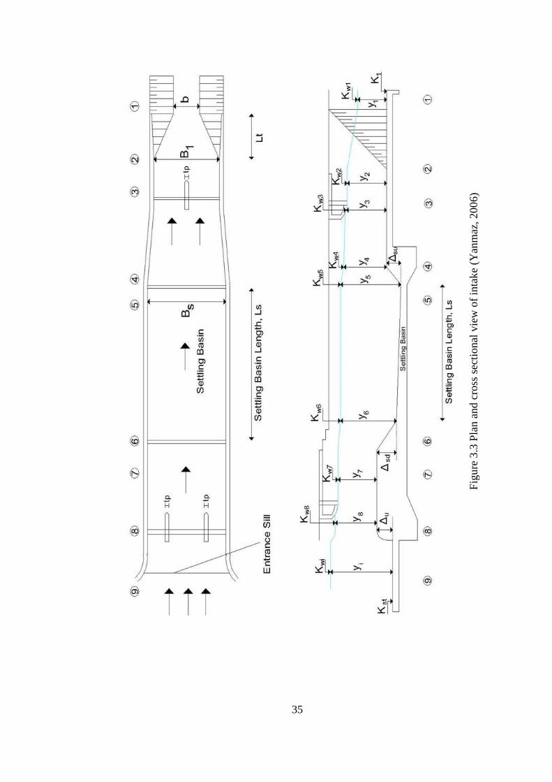
35
Fig
ure
3.3
Pla
n a
nd c
ross
sec
tional
vie
w o
f in
tak
e (Y
anm
az, 200
6)

36
in which, the net width of the canal at section 3, B3n = B1 - nptp where, np is
the number of piers; tp is the thickness of piers; K is the orifice coefficient
and ∆Hg1 is the minor loss due to gate. The orifice coefficient, K, can be
taken as 0.65 (Sungur, 1988).
After obtaining u3, the water depth, y3, and water surface elevation, Kw3, at
section 3 are determined by the Equation (3.35) and (3.36) respectively.
( . )
( . )
Section-4: Section 3 is connected with a transition to the settling basin since
the width of settling basin is greater than the width of section 3. The width of
settling basin can be taken 1-2 m greater than the width of section 3 in order
to provide the sufficient flow area to satisfy the velocity condition in the
settling basin. The minor head loss caused by this transition, ΔHt2 is
computed similarly with section 2:
(
) ( . )
where, u3 and u4 are flow velocities at sections 3 and 4 respectively, Ct is the
contraction coefficient of the transition. Similarly with section 2, the water
depth, y4, and water surface elevation, Kw4, just downstream of the upward
step at the end of the settling basin is computed as follows:
( . )
( . 9)
Section-5: In order to prevent the entrainment of sediment to the canal and

37
divert the accumulated sediment to the flushing pipe, an upward sill is
provided at the end of the settling basin. A relatively low flow velocity is
required for the suspended particles to settle in the settling basin. The
relationship between the maximum permissible flow velocity in the settling
basin and the maximum diameter of the particle to be settled is defined as
(Camp, 1946):
√ ( . 0)
where, Vmax : maximum velocity in the settling basin in cm/s;
Dmax : maximum diameter of the particle in mm;
a : a coefficient determined according to the particle diameter.
The value of a for different particle diameters are (Camp, 1946):
a = 36 for Dmax ≥ 1 mm;
a = 44 for 0.1 mm < Dmax < 1 mm;
a = 51 for Dmax ≤ 0.1.
By selecting the height of upward sill at the end of the settling basin, Δsu,
between 0.5 m and 1.0 m and applying the energy equation between sections
4 and 5:
( . 1)
where, u5 = Q / (Bsy5), and ΔHe is the minor loss caused by the upward sill.
ΔHe is computed from (Sungur, 1988):

38
(
⁄ √ ) ( . 2)
where, Bs is the width of the settling basin. The water depth at section 5, y5,
can be computed from Equations (3.41) and (3.42) while u5 is smaller than
the maximum velocity, Vmax, obtained from Equation (3.40). In case of
u5 > Vmax, firstly, Δsu is increased up to 1 m. If the condition of u5 ≤ Vmax is
not satisfied, the width of settling basin, Bs, is incremented until u5 ≤ Vmax
and the computations are repeated from section 4 since the value of Bs is also
used in calculations at section 4. After obtaining u5 and y5, the water surface
elevation Kw5 is obtained from:
( . )
Section-6: The settling basin starts from section 6 and ends at section 5. In
order to determine the water depth at section 6, the length of settling basin,
Ls, should be determined. To divert the settled sediment to the flushing pipe
at the end of the settling basin, a relatively steep slope of S0s = 0.01 (Sungur,
1988) is assigned through the length of the settling basin. In addition, the
settling basin should have sufficient length and depth to capture the sediment
particles. For this reason, the length of settling basin, Ls, is determined from:
( . )
where, Qd : design discharge;
Bs : width of the settling basin;
Wf : Fall velocity of the particle;
The relation between the size of the particle and fall velocity (Wf) for quartz
sand in water at 20o is given as (Breuser and Raudviki, 1991):

39
for Dm < 0.15 mm; ( . )
for Dm > 1.5 mm; √ ( . )
where, Dm is median sediment size in mm and Wf is in mm/s. For the particle
sizes within the range of 0.1 ≤ Dm ≤ 1.5 mm, the values of Wf are given in
Table 3.1.
Table 3.1 Fall velocities for quartz sand (Breuser and Raudviki, 1991)
Dm (mm) Wf (mm/s)
0.15 14.8
0.20 21.0
0.30 36.0
0.40 50.0
0.50 64.0
0.60 76.4
0.70 88.6
0.80 99.0
0.90 110.0
1.00 121.0
1.20 137.3
1.50 166.0
Particles of considerable size can damage the penstock and the turbines.
Therefore, the median size of the particles to be settled in the settling basin,
Dm, should be determined according to the head of the plant along with the
turbine type and operational conditions. Since the damage caused by the
entrainment of particles to the turbine can be devastating, the median particle
size must be determined carefully by consulting the turbine manufacturer.
After the fall velocity is obtained for the particle size, Dm, the length of the
settling basin, Ls, is calculated by using Equation (3.44). To be on the safe
side, the obtained value of Ls may be incremented by 2.0 m (Yanmaz, 2006).
After the determination of Ls, the water depth at the beginning of settling
basin, y6, is obtained from:

40
( . )
where, ΔHs is the head loss caused by friction through the settling basin
which is calculated by:
( . )
where, is the average friction slope between section 5 and 6 which is
calculated from:
(
(
) )
( . 9)
where, A6 = Q / u6 and y6 = Q / (Bsu6) and R5 is the hydraulic radius at
section 5. Therefore, by solving Equations (3.47) and (3.49) simultaneously,
water depth, y6, and flow velocity, u6, at section 6 can be determined. Then
the water surface elevation at section 6, Kw6 is calculated by the following
equation:
( . 0)
Section-7: As seen in Figure . , a downward step with a height of ∆sd is
placed at the beginning of the settling basin. The minor loss caused by this
step can be taken as ∆Hes = 0.02 m (Sungur, 1988). Therefore, the water
depth in section 7, y7, is obtained from:
( . 1)
where, u7 = Q / (Bsy7). The water surface elevation at section 7, Kw7, is
computed from:

41
( . 2)
Section-8: Similarly with section 3, a minor loss, ∆Hei, which is caused by
the submerged curtain wall located at the entrance of the intake is computed
from:
√ ( . )
in which, the net width, Bsn = Bs - npitpi where, npi is the number of piers; tpi is
the thickness of piers; K is equal to 0.65 (Sungur, 1988). The water depth, y8,
and water surface elevation, Kw8, at section 8 are determined by the following
equations:
( . )
( . )
Section-9: This is the entrance of the intake. An upward sill is provided with
a height of ∆u at this section. The reason for this upward sill is that to prevent
the entrainment of bed material into the intake. Similarly with section 4, the
minor loss caused by this sill, ∆Hi, is calculated by (Sungur, 1988):
(
⁄ √ ) ( . )
In addition to this minor loss at this section, the minor loss caused by the
trashracks, ∆Htr can be determined by (Baban, 1995):
[
(
)
]
( . )
where An is the net area through the rack bars, Ag is the gross area at the

42
beginning of the intake and un = Q / An. Then, the water surface elevation,
Kwi is calculated by the following equation:
( . )
After Kwi is obtained, the height of the upward sill at the entrance of the
intake, ∆u, which is in the range of 0.5 m to 1.0 m (Sungur, 1988), is
calculated by:
( . 9)
where, Kst is the thalweg elevation at the entrance of the intake. If the value
of ∆u is not in the mentioned range, the calculations from section 7 to section
9 are repeated by changing the value of ∆sd, until the condition is satisfied.
For the fluctuations of water level in front of the intake, the value of Kwi is
increased by 10 cm in order to determine the required crest elevation of the
overflow spillway, Ks. The height of the spillway, P, is determined by
subtracting the thalweg elevation at the spillway axis, Kst from the crest
elevation of the spillway, Ks.
3.5.2 Design of Spillway and Sluiceway
The river discharge is transmitted to downstream through sluiceway and over the
spillway. Before the design of energy dissipators, the spillway and sluiceway
discharges, Qs, Qsl, respectively, should be determined. Since the design discharge,
Q100, is transmitted by the sluiceway and spillway simultaneously, the determination
of Qs and Qsl is an iterative process (Yanmaz, 2006). This process is explained
below with reference to Figure 3.4 and 3.5. The condition to be satisfied is
expressed as:
( . 0)
The discharge over the spillway, Qs, can be computed from:

43
( . 1)
where Com is the overall modified discharge coefficient according to USBR (1987)
requirements, Leff is the effective length of spillway and H0 is the design spillway
head. The discharge through the sluiceway can be determined from:
√ ( . 2)
where, C′ is the orifice coefficient which can be taken as 0.65, nsl, Le and dsl are the
number of sluiceways, width and depth of sluiceway gates, respectively, and h is the
upstream water depth.
Figure 3.4 Cross-sectional view of spillway axis (Yanmaz, 2006)
Sluiceways
dsl
Le tsl
Spillway body
LT
L
K100
Ks
Ksl
Kst

44
Figure 3.5 Flow over the spillway and through the sluiceway (Yanmaz, 2006)
For an assumed value of upstream water level, K100, the necessary variables of
upstream water depth, h, velocity head, ha, and design spillway head, H0, are
determined from the following equations:
( . )
(
)
( . )
( . )
Kd100
h
EGL
H0
∆s
y1 y2 y3 Kr
∆E E3s
Eu
K100
Kst
(a) Flow over the spillway
H
ha Ks
Kst
h
d
EGL
∆sl
y1
∆E E3sl
y2
y3 Kr
Kd100
Eu
K100
(b) Flow through the sluiceway
Ksl
(1) (2) (3)
(1) (2) (3)

45
where, LT is the total length of the valley. If Equation (3.60) is not satisfied for the
assumed value of K100, the calculations are made for new values of K100 until
Equation (3.60) holds true. The same process is applied for all of the flood
discharges and the corresponding Qs and Qsl values are obtained (Yanmaz, 2006).
3.5.3 Design of Energy Dissipators
The river flow that is transmitted over the spillway and through the sluiceway
creates different flow conditions at the toe of the structure. Therefore, the analysis of
these sections must be carried out separately. Furthermore, these two different flow
conditions may result in different types of energy dissipators for their respective
sections. The procedure for the design of energy dissipators is as follows with
reference to Figure 3.5:
The relationship between the conjugate depths for a rectangular basin with known
upstream conditions is given as:
(√
) ( . )
where, Fr1 = u1 / √ is the Froude number of the flow at section 1 (see Figure 3.5).
The upstream energy level, Eu, the energy level downstream of the spillway, E3s, and
sluiceway, E3sl, are computed by the following equations respectively (Yanmaz,
2006):
( . )
(
)
( . )
(
( ( ) ) )
( . 9)
where, y3 is the water depth at the riprap section, L is the crest length of the
46
spillway, nsl is the number of sluiceways, Le is the width of the sluiceway and tsl is
the thickness of one pier.
After the computation of upstream and downstream energy levels for both spillway
and sluiceway, the energy loss caused by hydraulic jump can be calculated if the
head loss at the face of the spillway is ignored. By writing the energy equation
between the upstream and riprap section, the head losses can be determined by the
following equations:
( . 0)
( . 1)
The energy loss caused by a hydraulic jump in a rectangular basin is calculated by:
( )
( . 2)
By inserting Equation (3.72) into Equation (3.66), the following expression is
obtained (Yanmaz, 2006):
[
(√
) ]
(√
)
( . )
in which, y1 is the water depth at section 1, q = Q / L where L is the width of the
stilling basin. Equation (3.73) can be solved for y1 and the sequent depth of
hydraulic jump, y2, is obtained from Equation (3.66). The required sill height at the
end of the stilling basin, ∆, is obtained by applying energy equation between
sections 2 and 3. In addition, the stilling basin type is selected according to the
values of Froude Number, Fr1, and velocity, u1, at section 1 (USBR, 1987). The
above process is applied for both spillway and sluiceway. If the final design of
stilling basins at the toe of the spillway and sluiceway are one of USBR Type II, III

47
or IV, then the below inequality is checked in order to decide whether a separate or
common stilling basin is to be constructed (Yanmaz, 2006).
| | ( . )
where, ∆s is the end sill height for spillway section and ∆sl is the end sill height for
sluiceway section. If the above inequality does not hold true, a separate design of
stilling basins should be considered for sluiceway and spillway sections. If
inequality (3.74) is satisfied, then a common design should be considered with a end
sill having the greater magnitude of ∆s and ∆sl values.

48
CHAPTER 4
4. DEVELOPMENT OF COMPUTER SOFTWARE
In this study, a computer software is developed which aims the hydraulic design of
small scaled run-of-river type hydropower projects. The computer software called
MiniHEPP Hydraulic Design is capable of determining optimum design discharge of
the system using the available flow-duration data and designing the diversion weir,
canal, forebay, and penstock from the hydraulics point of view. The general
algorithms of the program and each of its modules are explained in this chapter.
MiniHEPP Hydraulic Design is developed in C# programming language and works
under Microsoft Windows operating system. It is a user-friendly computer program
that provides a simple and easy to use working environment to the user. Mainly, the
program consists of a main input window backed up with several output windows.
Hydropower projects include many different structural components and each
structural component has a different purpose in the system. However, the
characteristics of these structural components differ from project to project
depending on the topographic and geological conditions of the site. Therefore, the
properties of components are limited in the scope of the computer program. The
main types of components that are considered in the software are listed as:
Diversion Weir : Overflow spillway, sidewise intake.
Conveyance Line : Canal with rectangular or trapezoidal cross-section.
Forebay : Since the conveyance line is operating under open channel flow
conditions, a forebay is considered instead of a surge tank.

49
Penstock : Single penstock is taken into account.
4.1 Algorithms of the Program
The hydraulic design of a small hydropower plant is carried out in a logical
sequential manner. The calculations that are explained in Chapter 3 are needed to be
performed in the right order to satisfy the hydraulic requirements of the structural
components. In this chapter, the algorithms that are utilized to carry out the
aforementioned calculations are explained.
4.1.1 General Flow of the Program
MiniHEPP Hydraulic Design is developed to carry out the hydraulic design of
diversion weir, canal, forebay, and penstock components of small scaled run-of-river
hydropower plants. In addition, the program is capable of calculating the optimum
design discharge and penstock diameter. After the related input data are entered, the
design process begins with the optimization of the design discharge and follows with
the design of the components. Since the system is in subcritical flow conditions, the
computations of the hydraulic design of the system are carried out from the
downstream to the upstream direction. Therefore, after the design discharge is
obtained, the calculations start with the design of penstock and end with the design
of diversion weir. The general flowchart of the program is given in Figure 4.1. The
algorithm for the design of different components, which are carried out by different
program modules, are explained in this chapter.

50
Figure 4.1 General flowchart of the software
4.1.2 Algorithm for the Determination of Optimum Design Discharge and
Optimum Penstock Diameter
In order to make a selection between different design discharge alternatives, the
corresponding energy generation benefits and related costs are needed to be
START
INPUT DATA
OVERALL DIMENSIONS OF
HYDRAULIC STRUCTURES
SUBROUTINE: DESIGN DISCHARGE OPTIMIZATION
SUBROUTINE: PENSTOCK DIAMETER OPTIMIZATION
END
SUBROUTINE: PENSTOCK DESIGN
SUBROUTINE: FOREBAY and CANAL DESIGN
SUBROUTINE: DIVERSION WEIR DESIGN
51
calculated. However, one the most important factors in the process of optimization
of design discharge is the characteristics of penstock. The main reason is that the
great portion of the hydraulic losses are caused by the flow through the penstock.
Also, the cost of penstock changes dramatically by the change of its diameter.
Therefore, the design of penstock should be made in detail in order to obtain a more
accurate optimization result. In order to carry out the process explained in Chapter 3,
this part of the program requires inputs related hydroelectrical outputs as well as the
penstock characteristics. The inputs for this module are:
Flow-Duration curve,
Gross head, Hg,
Unit cost of penstock, Cup,
Unit cost of installed capacity, Cicu,
Firm energy unit price, Pfirm,
Secondary energy unit price, Psec,
Capital recovery factor, CRF,
Average turbine efficiency, et,
Average generator efficiency, eg,
Average transformer efficiency, eh,
Penstock length, L,
Friction factor in the penstock, f,
Allowable tensile strength of penstock material, σt,
Elasticity modulus of penstock material, E,
Number of bends in the penstock route with their respective bend angles,
Turbine closure time Tc.
The flow-duration curve is an input by means of river discharges with their
respective exceedence probabilities. The values of flow-duration curve are entered
with 5% increments of exceedence probability.
Although there are many types of minor losses occuring between the intake section
of the forebay and the turbine in the power house, the only type of minor losses

52
considered in this study are the bend losses. The minor losses caused by trashracks
and transitions are not considered by this program. The minor loss coefficient, Km,
may be determined by the following expressions (Yıldız, 1992):
for ∆b ≤ 2 o; ( .1)
for ∆b ≤ 90o and Rb/D > 2; ( .2)
where, ∆b is the angle of bend, Rb is the radius of bend and D is the penstock
diameter. After Km is obtained, the hydraulic loss caused by bends is calculated
using Equation (3.4).
After the input variables are entered, the process explained in detail in Chapter 3 is
carried out by the program. The design discharge is obtained by selecting the one
that gives the maximum net benefit. After the design discharge is obtained, the
calculated value of penstock diameter while optimizing the design discharge, is
taken as the initial value of penstock diameter. By increasing the penstock diameter
with 10 cm increments and calculating the necessary values, the program compares
10 alternatives and selects the penstock diameter alternative that gives minimum
total cost. The general flowchart for this module is given in Figure 4.2.
The outputs for this part are:
Design discharge, Qd,
Penstock Diameter, D,
Net head at design discharge, Hn,
Power generated by the plant, Pp,
Firm, secondary, and total energy generation, Ef, Es, Et.

53
Figure 4.2 Flowchart describing design discharge and penstock diameter
optimization
4.1.3 Program Module for Penstock Design
The input data related to penstock are also needed for design discharge and penstock
diameter optimization processes. After the penstock diameter optimization results
are obtained, these input data, are transferred to penstock design module. The most
important output for penstock design is the wall thickness, t. The flowchart
representing the determination of wall thickness is given in Figure 4.3. After the
wall thickness of penstock is determined, the following parameters are computed:
START
INPUT DATA
-Design Discharge
-Penstock Diameter
SUBROUTINE: Design Discharge Optimization
SUBROUTINE: Penstock Diameter Optimization
END

54
Wave speed, aw,
Pressure increase due to water hammer, ∆H,
Maximum head at the end of penstock, H0 + ∆H,
Aeration pipe diameter, DA,
Head loss due to friction and bends through penstock, hl.
Figure 4.3 Flowchart describing determination of penstock wall thickness
START
INPUT DATA
-PENSTOCK WALL THICKNESS
Assume t = tmin
SUBROUTINE: WAVE SPEED
SUBROUTINE: WATER HAMMER HEAD
σt σtall
NO
YES Increase t
END

55
4.1.4 Program Module for Forebay and Canal Design
As explained in Chapter 3, the designs of forebay and canal are made
simultaneously in the present study. Therefore, the design of both structural
component is included in the same module. The input variables for this module are:
Penstock invert elevation, Kpi,
Required volume of forebay,
Canal bed slope, So,
Canal side slopes, m,
Manning’s roughness coefficient through the canal, n.
This program module gives the following outputs:
Forebay length, Lfb,
Forebay width, Bfb,
Minimum water level in forebay, MinWL,
Normal operating water level in forebay, NWL,
Maximum water level in forebay, MaxWL,
Trashrack width at the forebay intake, Btr,
Side spillway crest elevation, Ksf,
Forebay wall crest elevation,
Forebay bottom elevation,
Step height in front of the forebay intake, ∆e,
Canal width, b,
Canal water depth at design discharge, d,
Canal bottom elevation at the exit, Kcd,
Water surface elevation at the canal exit.
4.1.5 Program Module for Design of Diversion Weir
In this study, the design of diversion weir with the overflow spillway having a

56
lateral intake is considered. In this module, the design of intake structure and energy
dissipators are included.
4.1.5.1 Algorithm for Design of Intake
Since the calculations are made from the dowstream to the upstream, the design of
intake is performed after the design of forebay and canal. Therefore, starting
boundary condition for intake design is the water surface elevation at the entrance of
the canal. In order to obtain the water level and bottom elevation at the entrance of
the canal, the only remaining input is the canal length, since the required
information regarding the canal is obtained at the stage of canal design. The
necessary input variables for this module are listed as:
Length of canal, Lc,
Number of piers at the canal entrance, np,
Thickness of piers at the canal entrance, tp,
Number of piers at the intake entrance, npi,
Thickness of piers at the intake entrance, tpi,
Maximum settlement diameter, Dmax,
Manning’s roughness coefficient in the settling basin, ns,
Maximum spacing between rackbars at the intake entrance, str,
Thickness of rackbars at the intake entrance, ttr,
Thalweg elevation, Kst.
Starting from the canal entrance, the head losses occured in all of the sections are
calculated. The water surface profile between the intake structure and the canal
entrance is determined and the dimensions of each section are obtained as explained
in Chapter 3. At the end of this procedure, the crest elevation of overflow spillway is
also determined. The flowchart representing the design of intake is given in Figure
4.4.
After the mentioned procedure is processed, the following outputs are obtained from
this module:

57
Figure 4.4 Flowchart describing the design of intake
START
INPUT DATA
-Dimensions and water levels of intake sections
-Spillway crest elevation
SUBROUTINE: Section 1
u1 > u2 NO
YES
Increase B2
END
SUBROUTINE: Section 2
SUBROUTINE: Section 3
SUBROUTINE: Section 4
SUBROUTINE: Section 5
u5 < u5max ∆su = 1 m
YES
NO
SUBROUTINE: Section 6
SUBROUTINE: Section 7
SUBROUTINE: Section 8
SUBROUTINE: Section 9
0. m < ∆u < 1.0 m
YES
YES
Increase B5
NO
Increase ∆su
Increase or
decrease ∆sd
58
Water levels for each of the intake sections,
Overall dimensions for each of the intake sections,
Spillway crest elevation, Ks.
4.1.5.2 Program Module for the Design of Energy Dissipator
In order to design the energy dissipator, the discharge that will pass through the
sluiceway, Qsl, and over the spillway, Qs, need to be determined, as explained in
Chapter 3. For each flood discharge, Q5, Q10, Q25, Q50 and Q100, the values of Qs and
Qsl are determined along with the corresponding upstream water level, Ki. The
flowchart that represents the determination of Qs and Qsl is given in Figure 4.5.
After the values of Qs, Qsl and Ki are determined for each flood discharge, this
module designs energy dissipators according to USBR (1987) specifications for
stilling basins having rectangular cross-sections. USBR Type II, III and IV stilling
basins are included in this module since these types are the most common. The
flowchart for the design of energy dissipator is given in Figure 4.6.
The input data needed for this module are:
Flood discharges, Q5, Q10, Q25, Q50, Q100,
Riprap section water level for each flood discharge, Kd5, Kd10, Kd25, Kd50,
Kd100,
Riprap section bottom elevation, Kr,
Spillway crest elevation, Ks,
Spillway crest length, Lspill,
Depth of sluiceway gates, dsl,
Width of sluiceway gates, Le,
Number of sluiceway gates, nsl,
Thickness of walls between sluiceway gates, tsl.

59
Figure 4.5 Flowchart describing the determination of sluiceway and spillway
discharges
START
INPUT DATA
-Spillway discharge, Qs
-Sluiceway discharge, Qsl
-Corresponding upstream water level, Ki
Assume Ki = Ks
SUBROUTINE: Spillway Discharge
SUBROUTINE: Sluiceway Discharge
Qs + Qsl ≥ Qi
NO
YES Increase Ki
END

60
Figure 4.6 Flowchart describing the design of energy dissipators
START
INPUT DATA
-Energy dissipator types and
corresponding dimensions
SUBROUTINE: Sluiceway energy
level, for each flood discharge
Energy dissipators are
one of USBR Type II,
III, IV
NO
YES
END
SUBROUTINE: Spillway energy
level, for each flood discharge
SUBROUTINE: Sluiceway energy
dissipator for each flood discharge
SUBROUTINE: Spillway energy
dissipator for each flood discharge
TERMINATE TERMINATE NO
SUBROUTINE: Sluiceway energy
dissipator selection according to Lsl
and ∆sl
SUBROUTINE: Spillway energy
dissipator selection according to Ls
and ∆s
YES
|∆sl - ∆s| < 50 cm
SUBROUTINE: Seperate energy
dissipator with common length
SUBROUTINE: Common energy
dissipator
YES NO

61
In addition, in case of an existence of a bridge over the spillway, the following input
variables are also needed:
Thickness of piers of bridge, tbp,
Number of piers of bridge, nbp,
Contraction coefficient due to abutments, Kab,
Contraction coefficient due to piers, Kp.
This module gives the following outputs after execution:
Discharge over spillway for each flood discharge,
Discharge through sluiceway for each flood discharge,
Upstream water level for each flood discharge,
Spillway and sluiceway energy dissipator types and corresponding
dimensions considering separate or common design decision.
4.2 Interface of the Program
MiniHEPP Hydraulic Design is a user-friendly program. The user interface is simple
and easy to use. The detailed information about the interface along with user manual
is given in Appendix A.

62
CHAPTER 5
5. APPLICATION
The hydraulic design of a run-of-river type hydropower plant is to be performed
with MiniHEPP Hydraulic Design. The characteristics of the structural components
and the input data necessary to execute the program are given in this chapter. In
addition, the obtained dimensions and related outputs are also given.
5.1 Characteristics of the System and Input Data
5.1.1 Hydrological Data
As mentioned before, MiniHEPP Hydraulic Design is not capable of performing
hydrological analysis. At the start of the execution of the program, it is assumed that
the hydrological analysis of the river has been completed. Hence, the flow duration
curve and flood data are input for the execution of the program. In this chapter, data
of an existing project will be used to demonstrate the use of the software developed
in the present study, Paşa HPP located in Bolu, Turkey. It’s a run-of-river type
hydropower plant. The flow duration curve for Paşa HPP is provided in Figure 5.1
and flood discharges and water surface elevations at riprap section can be found in
Table 5.1.

63
Figure 5.1 Flow duration curve
The power duration curve is generated from the flow duration curve represented in
Figure 5.1. The power duration curve is given in Figure 5.2.
Figure 5.2 Power duration curve
0
5
10
15
20
25
30
35
40
45
0 20 40 60 80 100
Q (
m3/s
)
Percent time (%)
0
5
10
15
20
25
30
0 20 40 60 80 100
Pow
er (
MW
)
Percent time (%)

64
Table 5.1 Flood discharges and water surface elevations at riprap section
Flood Discharge
Discharge
(m3/s)
Water Surface Elevations at
Riprap Section (m)
Q5 113.6 589.49
Q10 139.7 589.85
Q25 175.7 590.32
Q50 205.2 590.68
Q100 237.4 591.06
5.1.2 Penstock Inputs
A single penstock connected with two branches to the turbines is to be constructed
between the forebay and power house. The related input variables regarding
penstock are listed as follows:
Length of penstock, Lpen = 254.00 m,
Friction factor, f = 0.012,
Elasticity modulus of pipe material, E = 206 GPa,
Allowable tensile stress, σt = 400 MPa,
Unit price of penstock, Cpu = 7.52 $/kg,
Turbine closure time, Tc = 5 sec,
Number of penstocks, npen = 1,
Penstock invert elevation, Kpi = 581.25 m,
Bulk modulus of elasticity of water, K = 2200 GPa.
The annual cost of penstock, Cp, in US dollars is determined using Equation (3.7)
and (3.8) as explained in Chapter 3. For the sake of simplicity in calculations, the
following power equation is fitted to the results having a correlation coefficient of
0.99:
( .1)

65
where D is penstock diameter in m.
5.1.3 Canal and Forebay Inputs
The canal between the diversion weir and forebay has a trapezoidal cross-section
having side slopes 1V:1.5H. The other necessary information for canal design is
listed below:
Canal side slope, m = 1.5,
Roughness coefficient, n = 0.016,
Canal bottom slope, S0 = 0.0003,
Canal length, Lcanal = 17214 m.
5.1.4 Intake Inputs
The sidewise intake structure will divert the flow at the left bank. The necessary
input variables for the design of intake are given as:
Number of piers at section 3, np = 1,
Thickness of piers at section 3, tp = 0.5 m,
Number of piers at section 8, npi = 1,
Thickness of piers at section 8, tpi = 0.5 m,
Maximum settlement diameter, Dmax = 0.2 mm,
Thickness of rackbars at section 8, ttr = 0.015 m,
Maximum spacing between rackbars at section 8, str = 0.10 m,
Roughness coefficient at settling basin, ns = 0.016.
5.1.5 Spillway, Sluiceway and Energy Dissipator Inputs
For the design of energy dissipators, the dimensions of overflow spillway and
sluiceway are needed. A bridge is not preferred to be constructed on the spillway
and the upstream face of spillway is not inclined. The remaining data are listed as:

66
Number of sluiceway gates, nsl = 1,
Width of sluiceway gate, wsl = 4.50 m,
Height of sluiceway gate, dsl = 2.00 m,
Spillway crest length, Lspill = 60 m,
Bed elevation at riprap section, Kr = 587.00 m,
Thalweg elevation at the entrance of intake, Kst = 589.40 m.
5.1.6 Power House and General System Inputs
Finally, the remaining necessary input variables are given as follows:
Gross head, Hg = 78.00 m,
Number of turbines, ntur = 2,
Turbine efficiency, et = 0.94,
Generator efficiency, eg = 0.97,
Transformer efficiency, eh = 0.98,
Firm energy unit price, Pfirm = 8 $/kWh,
Secondary energy unit price, Psec = 8 $/kWh,
Unit cost of installed capacity, Cicu = 1,200,000 $/MW,
Capital recovery factor, CRF = 0.11.
5.2 Calculations and Outputs
MiniHEPP Hydraulic Design was executed in order to perform the hydraulic design
of structures with the input data given in previous sections. The program follows the
procedure explained in detail in Chapter 3.
After the program is executed, the optimum design discharge, Qd, is obtained as
10.79 m3/s (see Figure 5.3) and the corresponding optimum penstock diameter, D,
and installed capacity, Pp, are calculated as 1.70 m (see Figure 5.4), 7.18 MW (see
Figure 5.5) respectively. The outputs of the program are presented in Table 5.2.

67
Figure 5.3 Determination of optimum discharge
Figure 5.4 Determination of optimum penstock diameter

68
Figure 5.5 Determination of optimum installed capacity

69
Table 5.2 Outputs of execution
Unit MiniHEPP HD Outputs
Design Discharge, Qd m3/s 10.79
Penstock Diameter, D m 1.70
Crest elevation of spillway, Ks m 593.24
Maximum water level for Q100, K100 m 594.44
Intake entrance bottom elevation m 590.55
Settling basin length, Ls m 33.76
Settling basin width, Bs m 16.18
Velocity in settling basin, u5 m/s 0.197
Forebay width, Bfb m 18.10
Forebay length, Lfb m 52.80
Minimum water level in the forebay,
MinWL m 586.90
Normal water level in the forebay,
NWL m 587.66
Maximum water level in the
forebay, MaxWL m 587.98
Forebay wall crest elevation m 588.08
Penstock wall thickness, t mm 8.00
Installed capacity, Pp MW 7.18
Firm Energy, Ef GWh/year 8.34
Seconder Energy, Es GWh/year 22.97
Total Energy, Et GWh/year 31.31
Energy dissipator length m 31.00
Energy dissipator type USBR Type IV
However, in Paşa HPP the design discharge is taken as 13.50 m3/s and the penstock
diameter is taken as 2.40 m. The reason for these differences may be caused by the
selection of different unit costs for penstock and installed capacity or different
energy benefit values for firm and secondary energy generation. Therefore, to
provide a better comparison with an existing project, the program is executed with
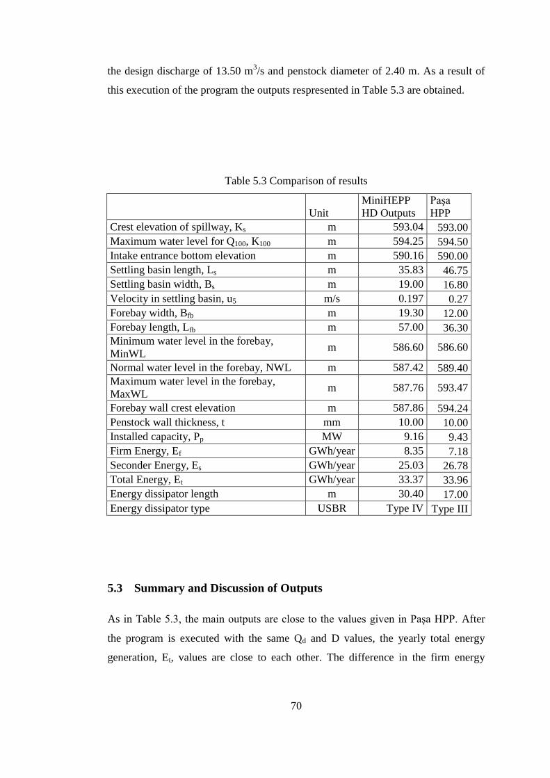
70
the design discharge of 13.50 m3/s and penstock diameter of 2.40 m. As a result of
this execution of the program the outputs respresented in Table 5.3 are obtained.
Table 5.3 Comparison of results
Unit
MiniHEPP
HD Outputs
Paşa
HPP
Crest elevation of spillway, Ks m 593.04 593.00
Maximum water level for Q100, K100 m 594.25 594.50
Intake entrance bottom elevation m 590.16 590.00
Settling basin length, Ls m 35.83 46.75
Settling basin width, Bs m 19.00 16.80
Velocity in settling basin, u5 m/s 0.197 0.27
Forebay width, Bfb m 19.30 12.00
Forebay length, Lfb m 57.00 36.30
Minimum water level in the forebay,
MinWL m 586.60 586.60
Normal water level in the forebay, NWL m 587.42 589.40
Maximum water level in the forebay,
MaxWL m 587.76 593.47
Forebay wall crest elevation m 587.86 594.24
Penstock wall thickness, t mm 10.00 10.00
Installed capacity, Pp MW 9.16 9.43
Firm Energy, Ef GWh/year 8.35 7.18
Seconder Energy, Es GWh/year 25.03 26.78
Total Energy, Et GWh/year 33.37 33.96
Energy dissipator length m 30.40 17.00
Energy dissipator type USBR Type IV Type III
5.3 Summary and Discussion of Outputs
As in Table . , the main outputs are close to the values given in Paşa HPP. After
the program is executed with the same Qd and D values, the yearly total energy
generation, Et, values are close to each other. The difference in the firm energy
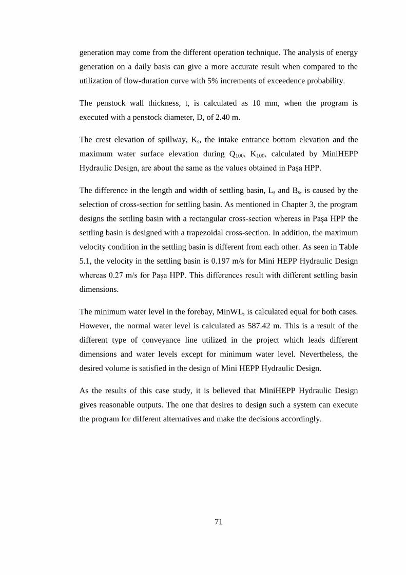
71
generation may come from the different operation technique. The analysis of energy
generation on a daily basis can give a more accurate result when compared to the
utilization of flow-duration curve with 5% increments of exceedence probability.
The penstock wall thickness, t, is calculated as 10 mm, when the program is
executed with a penstock diameter, D, of 2.40 m.
The crest elevation of spillway, Ks, the intake entrance bottom elevation and the
maximum water surface elevation during Q100, K100, calculated by MiniHEPP
Hydraulic Design, are about the same as the values obtained in Paşa HPP.
The difference in the length and width of settling basin, Ls and Bs, is caused by the
selection of cross-section for settling basin. As mentioned in Chapter 3, the program
designs the settling basin with a rectangular cross-section whereas in Paşa HPP the
settling basin is designed with a trapezoidal cross-section. In addition, the maximum
velocity condition in the settling basin is different from each other. As seen in Table
5.1, the velocity in the settling basin is 0.197 m/s for Mini HEPP Hydraulic Design
whereas 0.2 m/s for Paşa HPP. This differences result with different settling basin
dimensions.
The minimum water level in the forebay, MinWL, is calculated equal for both cases.
However, the normal water level is calculated as 587.42 m. This is a result of the
different type of conveyance line utilized in the project which leads different
dimensions and water levels except for minimum water level. Nevertheless, the
desired volume is satisfied in the design of Mini HEPP Hydraulic Design.
As the results of this case study, it is believed that MiniHEPP Hydraulic Design
gives reasonable outputs. The one that desires to design such a system can execute
the program for different alternatives and make the decisions accordingly.

72
CHAPTER 6
6. CONCLUSIONS AND RECOMMENDATIONS
6.1 Summary and Conclusions
In this study, a computer software called MiniHEPP Hydraulic Design is developed
for the hydraulic design of run-of-river hydropower plants. The program is capable
of selecting optimum design discharge and penstock diameter and performing the
hydraulic design of structural components, such as diversion weir, canal, forebay,
and penstock accordingly.
The main objective for this thesis is to create a guideline for the hydraulic design of
small run-of-river type hydropower plants and process this guideline in a logical
manner. Therefore, almost every structural component of these type of systems are
considered.
The program runs with the assumptions that the locations of the structures are pre-
determined and fairly close to their final locations and the topographic and
geological conditions are suitable. It is believed that one may run the program
succesively to include these kinds of effects, however limited, by changing the input
variables and make decisions for the final design of the project.
A case study was used to demonstrate the capabilities of the program developed in
the present study. The results showed that the program has achived the objectives of
the study within an acceptable accuracy.

73
6.2 Recommendations for Further Development
The computer program that is developed in this study is a basic introductory
guideline and software for the hydraulic design of small run-of-river type
hydropower plants. Since there are various kinds for each structural component, the
inclusion of different types of these components that is not considered in this study
can be suggested. In addition, the effect of topographic and geological conditions
can also be studied which leads to a need to design the components from a structural
point of view rather than only hydraulic. The possible inclusions can be summarized
as follows:
Different types of diversion weir intakes such as tyrolean or radial gates,
Appurtenant facilities of diversion weir and other structural components,
Conveyance line options other than canal and composite systems,
Design of forebay and penstock according to multiple number of penstocks,
Design of power house,
Design of turbines.

74
7. REFERENCES
Baban, R. B., (199 ). “Design of Small Diversion Weirs”, New York: John Wiley
and Sons.
Breusers, H.N.C., and Raudviki, A.J., (1991). “Scouring-Hydraulics Structures
Design Manual”, International Association for Hydraulic Research, A.A.
Bakema, Rotterdam/Brookfield, Netherlands.
Camp, T.R., (1946). “Sedimentation and the Design of Settling Tanks”, Transactions
ASCE, Vol. 3, No. 2285, pp. 895-936.
Chow, V.T., (1959). “Open Channel Hydraulics”, McGraw Hill, New York.
ESHA, (200 ). “Guide on How to Develop a Small Hydropower Plant”, Publication
of the European Small Hydropower Association.
French, R.H., (1987). "Open Channel Hydraulics", Singapore: McGraw Hill.
Knauss, J., (19 ). “Swirling Flow Problems at Intakes”, AIHR Hydraulic Structure
Design Manual, Rotterdam, Netherlands.
Sungur, T., (1988). “Hydraulic Structures-Vol.2: Diversion Weirs”, Ankara,
Publications of Turkish State Hydraulic Works (in Turkish).
Turan, K. H., (200 ). “Development of a Computer Program for Optimum Design of
Diversion Weirs”, M.Sc. Thesis, Department of Civil Engineering, METU,
Ankara.

75
USBR, (19 ). “Design of Small Dams”, Third Edition, Washington: Water
Resources Technical Publication.
USBR, (19 ). “Engineering Monograph No : Welded Steel Penstocks”, Revised
Edition, Washington: Water Resources Technical Publication.
Wylie, E.B., Streeter, V.L., and Suo L., (199 ). “Fluid Transients in Systems”,
Prentice Hall, NJ 07458.
Yanmaz, A.M., and Cihangir, E., (1996). “A Computer Program for Hydraulic
Design of Diversion Weirs with Lateral Intakes”, Turkish J. of Engineering
and Environmental Sciences, 20, pp. 1-6.
Yanmaz, A.M., (2006). “Applied Water Resources Engineering”, Third Edition,
METU Press, Ankara.
Yıldız, K., (1992). “Hydropower Plants: Calculation Guidelines and Design”,
Ankara, Publications of Turkish State Hydraulic Works (in Turkish).

76
APPENDIX A
8. USER-MANUAL FOR MINIHEPP HYDRAULIC DESIGN
A.1 Main Window of MiniHEPP Hydraulic Design
The window that appears after the program is started is the main window. It contains
the menu items and the input data pages as seen in Figure A.1.
Figure A.1 Main window of MiniHEPP Hydraulic Design

77
A.2 Menu Items
There are four menu item in the main window of MiniHEPP Hydraulic Design. Each
of these individual menu items have sub-menu items to group the related functions.
These menu items can be listed as:
File
Contains the related sub-menu items regarding file management.
View
Output windows are included in this menu item.
Design
The “Run” item, which will be activated by the user to make the program to
calculate the desired outputs, can be found under “Design”.
Help
The general information regarding the program can be found under the
“Help” item.
A.2.1 File Menu Item
Under this menu item, there exist three different sub-items as seen in Figure A.2.
These items are listed as follows:
Open
Opens a existing MiniHEPP Hydraulic Design file.
Save
Creates a MiniHEPP Hydraulic Design file under the desired location with a
desired name. The extension of files created by MiniHEPP Hydraulic Design
is “.hpp”. If there is a file with the same name entered in the save file dialog,
the existed file is overwritten by the new one.
Quit
Closes all the windows and quits the program.

78
Figure A.2 File menu items
A.2.2 View Menu Item
View menu item contains the output windows. Each of these seven output window
can be opened and closed seperately. The output windows, as can be seen in Figure
A.3, are:
General Characteristics of the Project
Optimization Results
o Installed Capacity Optimization
o Penstock Diameter Optimization
Penstock Characteristics
Canal and Forebay Characteristics
Intake Characteristics
Spillway and Energy Dissipators
These windows display the resulting values and dimensions regarding the part of the
calculations as their name implies. A typical output window is given in Figure A.4.
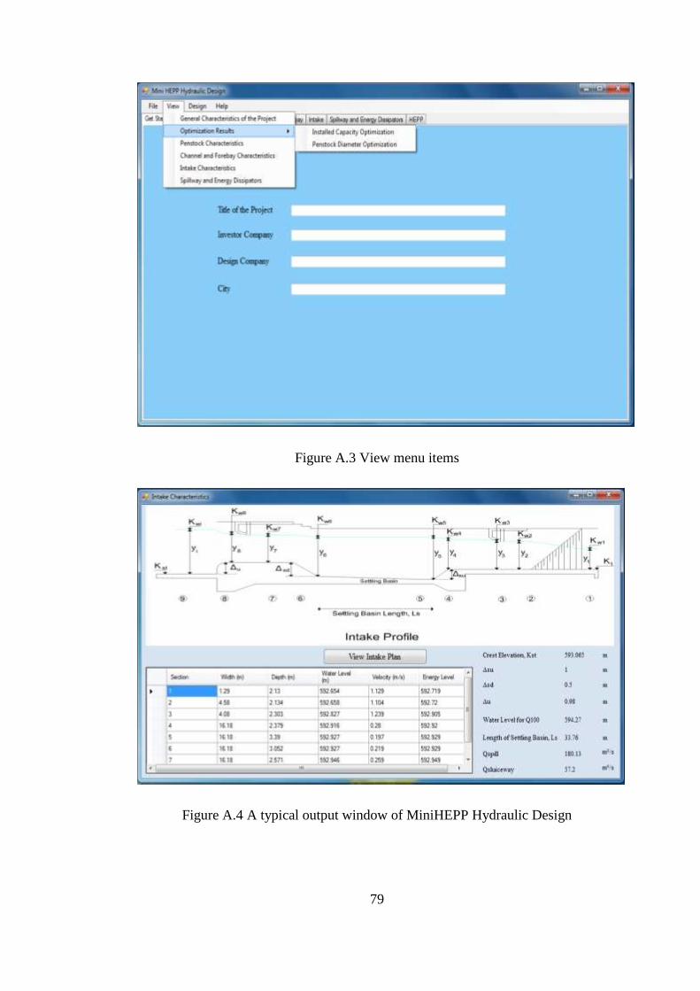
79
Figure A.3 View menu items
Figure A.4 A typical output window of MiniHEPP Hydraulic Design

80
A.3 Input Pages
The input pages are located in the main window of MiniHEPP Hydraulic Design.
The input pages are seperated and each of these pages have related sections for the
data to be entered regarding their corresponding parts. There are seven different
pages for input data which are as follows:
Get Started
Hydrological Data
Penstock
Canal and Forebay
Intake
Spillway and Energy Dissipators
HEPP
A typical input page is given in Figure A.5. After all the necessary input variables
are entered, the calculation process is started by clicking the “Run” item in the
“Design” menu. In order to obtain the outputs, all of the input data must be entered.
A.4 Tips for User
The MiniHEPP Hydraulic Design is capable of designing the system for a specified
design discharge and / or penstock diameter by ignoring the optimization results if
desired. By checking the coressponding box in the hydrological data page and
entering the desired values in the text box next to the check box, the program can be
run according to these values. This gives flexibility to the user in four different
design choice:
Design accoding to the optimization results for both design discharge and
penstock diameter
Design according to a design discharge specified by the user and penstock
optimization for this discharge
Design according to a penstock diameter specified by the user with the

81
design discharge taken from optimization results.
Design according to design discharge and penstock diameter choosen by the
user
Figure A.5 A typical input page of MiniHEPP Hydraulic Design

82
APPENDIX B
9. SOURCE CODE OF MINIHEPP HYDRAULIC DESIGN
/////////////////////////////////////////////////////////////////////////////////////////////
//Form Decleration: Form 1: Main and Input Page //
////////////////////////////////////////////////////////////////////////////////////////////
namespace WindowsFormsApplication1
{
public partial class Form1 : Form
{
public Form1()
{
Application.CurrentCulture =
System.Globalization.CultureInfo.CreateSpecificCulture("en-US");
InitializeComponent();
}
///////////////////////////////////////////////////////////////////////////////////////////
//Decleration: Main and Input Page //
//Menu Items and Page Functionalities //
/////////////////////////////////////////////////////////////////////////////////////////

83
private void menuQuit_Click(object sender, EventArgs e)
{
Application.Exit();
}
private void menuOpen_Click(object sender, EventArgs e)
{
openFD1.InitialDirectory = "C:";
openFD1.FileName = "";
openFD1.Filter = "MiniHEPP Projects|*.hpp";
openFD1.FileName = String.Empty;
DialogResult result = openFD1.ShowDialog();
if (result == DialogResult.OK)
{
Stream fs = openFD1.OpenFile();
StreamReader reader = new StreamReader(fs);
TitleBox.Text = reader.ReadLine();
InvestorBox.Text = reader.ReadLine();
DesignCoBox.Text = reader.ReadLine();
CityBox.Text = reader.ReadLine();
flowBox1.Text = reader.ReadLine();
flowBox2.Text = reader.ReadLine();
flowBox3.Text = reader.ReadLine();
flowBox4.Text = reader.ReadLine();
flowBox5.Text = reader.ReadLine();
flowBox6.Text = reader.ReadLine();

84
flowBox7.Text = reader.ReadLine();
flowBox8.Text = reader.ReadLine();
flowBox9.Text = reader.ReadLine();
flowBox10.Text = reader.ReadLine();
flowBox11.Text = reader.ReadLine();
flowBox12.Text = reader.ReadLine();
flowBox13.Text = reader.ReadLine();
flowBox14.Text = reader.ReadLine();
flowBox15.Text = reader.ReadLine();
flowBox16.Text = reader.ReadLine();
flowBox17.Text = reader.ReadLine();
flowBox18.Text = reader.ReadLine();
flowBox19.Text = reader.ReadLine();
flowBox20.Text = reader.ReadLine();
flowBox21.Text = reader.ReadLine();
PenLenBox.Text = reader.ReadLine();
FrictionFBox.Text = reader.ReadLine();
ElasticityBox.Text = reader.ReadLine();
StressBox.Text = reader.ReadLine();
PenCurveBigBox.Text = reader.ReadLine();
PenCurveSmallBox.Text = reader.ReadLine();
PenQuanBox.Text = reader.ReadLine();
PenEntElevBox.Text = reader.ReadLine();
RVCoeffBox.Text = reader.ReadLine();
PierNumberBox.Text = reader.ReadLine();

85
PierThickBox.Text = reader.ReadLine();
MaxSettDiaBox.Text = reader.ReadLine();
RemovalRatioBox.Text = reader.ReadLine();
RoughnessBox.Text = reader.ReadLine();
DRackBox.Text = reader.ReadLine();
tRackBox.Text = reader.ReadLine();
PierIntakeThickBox.Text = reader.ReadLine();
PierIntakeNumberBox.Text = reader.ReadLine();
KthalwegBox.Text = reader.ReadLine();
LspillBox.Text = reader.ReadLine();
AlphaBox.Text = reader.ReadLine();
wslBox.Text = reader.ReadLine();
nslBox.Text = reader.ReadLine();
dslBox.Text = reader.ReadLine();
tslBox.Text = reader.ReadLine();
KrBox.Text = reader.ReadLine();
Q5Box.Text = reader.ReadLine();
Kd5Box.Text = reader.ReadLine();
Q10Box.Text = reader.ReadLine();
Kd10Box.Text = reader.ReadLine();
Q25Box.Text = reader.ReadLine();
Kd25Box.Text = reader.ReadLine();
Q50Box.Text = reader.ReadLine();
Kd50Box.Text = reader.ReadLine();
Q100Box.Text = reader.ReadLine();

86
Kd100Box.Text = reader.ReadLine();
PenUnitCostBox.Text = reader.ReadLine();
TcBox.Text = reader.ReadLine();
headBox.Text = reader.ReadLine();
TurEffBox.Text = reader.ReadLine();
GenEffBox.Text = reader.ReadLine();
TranEffBox.Text = reader.ReadLine();
EnergyFPriceBox.Text = reader.ReadLine();
EnergySPriceBox.Text = reader.ReadLine();
CapCostBox.Text = reader.ReadLine();
CRFBox.Text = reader.ReadLine();
ChanSlopeBox.Text = reader.ReadLine();
ChanLenBox.Text = reader.ReadLine();
ChanSSlopeBox.Text = reader.ReadLine();
ChanRoughBox.Text = reader.ReadLine();
TurQuanBox.Text = reader.ReadLine();
TurTypeBox.Text = reader.ReadLine();
BridgePierNumberBox.Text = reader.ReadLine();
BridgePierThickBox.Text = reader.ReadLine();
KpBox.Text = reader.ReadLine();
KaBox.Text = reader.ReadLine();
DsgnDischargeBox.Text = reader.ReadLine();
PenDiaDsgnBox.Text = reader.ReadLine();
DsuMaxBox.Text = reader.ReadLine();
DsuMinBox.Text = reader.ReadLine();

87
DsdMaxBox.Text = reader.ReadLine();
DsdMinBox.Text = reader.ReadLine();
DuMaxBox.Text = reader.ReadLine();
DuMinBox.Text = reader.ReadLine();
reader.Close();
fs.Close();
}
}
private void menuSave_Click(object sender, EventArgs e)
{
string name = saveFD1.FileName;
saveFD1.Filter = "MiniHEPP Project|*.hpp";
saveFD1.FileName = String.Empty;
saveFD1.DefaultExt = ".hpp";
DialogResult result = saveFD1.ShowDialog();
if (result == DialogResult.OK)
{
FileStream fs = new FileStream(saveFD1.FileName, FileMode.Create);
StreamWriter writer = new StreamWriter(fs);
writer.WriteLine(TitleBox.Text);
writer.WriteLine(InvestorBox.Text);
writer.WriteLine(DesignCoBox.Text);
writer.WriteLine(CityBox.Text);
writer.WriteLine(flowBox1.Text);
writer.WriteLine(flowBox2.Text);

88
writer.WriteLine(flowBox3.Text);
writer.WriteLine(flowBox4.Text);
writer.WriteLine(flowBox5.Text);
writer.WriteLine(flowBox6.Text);
writer.WriteLine(flowBox7.Text);
writer.WriteLine(flowBox8.Text);
writer.WriteLine(flowBox9.Text);
writer.WriteLine(flowBox10.Text);
writer.WriteLine(flowBox11.Text);
writer.WriteLine(flowBox12.Text);
writer.WriteLine(flowBox13.Text);
writer.WriteLine(flowBox14.Text);
writer.WriteLine(flowBox15.Text);
writer.WriteLine(flowBox16.Text);
writer.WriteLine(flowBox17.Text);
writer.WriteLine(flowBox18.Text);
writer.WriteLine(flowBox19.Text);
writer.WriteLine(flowBox20.Text);
writer.WriteLine(flowBox21.Text);
writer.WriteLine(PenLenBox.Text);
writer.WriteLine(FrictionFBox.Text);
writer.WriteLine(ElasticityBox.Text);
writer.WriteLine(StressBox.Text);
writer.WriteLine(PenCurveBigBox.Text);
writer.WriteLine(PenCurveSmallBox.Text);

89
writer.WriteLine(PenQuanBox.Text);
writer.WriteLine(PenEntElevBox.Text);
writer.WriteLine(RVCoeffBox.Text);
writer.WriteLine(PierNumberBox.Text);
writer.WriteLine(PierThickBox.Text);
writer.WriteLine(MaxSettDiaBox.Text);
writer.WriteLine(RemovalRatioBox.Text);
writer.WriteLine(RoughnessBox.Text);
writer.WriteLine(DRackBox.Text);
writer.WriteLine(tRackBox.Text);
writer.WriteLine(PierIntakeThickBox.Text);
writer.WriteLine(PierIntakeNumberBox.Text);
writer.WriteLine(KthalwegBox.Text);
writer.WriteLine(LspillBox.Text);
writer.WriteLine(AlphaBox.Text);
writer.WriteLine(wslBox.Text);
writer.WriteLine(nslBox.Text);
writer.WriteLine(dslBox.Text);
writer.WriteLine(tslBox.Text);
writer.WriteLine(KrBox.Text);
writer.WriteLine(Q5Box.Text);
writer.WriteLine(Kd5Box.Text);
writer.WriteLine(Q10Box.Text);
writer.WriteLine(Kd10Box.Text);
writer.WriteLine(Q25Box.Text);

90
writer.WriteLine(Kd25Box.Text);
writer.WriteLine(Q50Box.Text);
writer.WriteLine(Kd50Box.Text);
writer.WriteLine(Q100Box.Text);
writer.WriteLine(Kd100Box.Text);
writer.WriteLine(PenUnitCostBox.Text);
writer.WriteLine(TcBox.Text);
writer.WriteLine(headBox.Text);
writer.WriteLine(TurEffBox.Text);
writer.WriteLine(GenEffBox.Text);
writer.WriteLine(TranEffBox.Text);
writer.WriteLine(EnergyFPriceBox.Text);
writer.WriteLine(EnergySPriceBox.Text);
writer.WriteLine(CapCostBox.Text);
writer.WriteLine(CRFBox.Text);
writer.WriteLine(ChanSlopeBox.Text);
writer.WriteLine(ChanLenBox.Text);
writer.WriteLine(ChanSSlopeBox.Text);
writer.WriteLine(ChanRoughBox.Text);
writer.WriteLine(TurQuanBox.Text);
writer.WriteLine(TurTypeBox.Text);
writer.WriteLine(BridgePierNumberBox.Text);
writer.WriteLine(BridgePierThickBox.Text);
writer.WriteLine(KpBox.Text);
writer.WriteLine(KaBox.Text);

91
writer.WriteLine(DsgnDischargeBox.Text);
writer.WriteLine(PenDiaDsgnBox.Text);
writer.WriteLine(DsuMaxBox.Text);
writer.WriteLine(DsuMinBox.Text);
writer.WriteLine(DsdMaxBox.Text);
writer.WriteLine(DsdMinBox.Text);
writer.WriteLine(DuMaxBox.Text);
writer.WriteLine(DuMinBox.Text);
writer.Close();
fs.Close();
}
}
private void ınstalledCapacityOptimizationToolStripMenuItem_Click(object
sender, EventArgs e)
{
Form2 CapOpt = new Form2();
CapOpt.Show();
}
private void penstockDiameterOptimizationToolStripMenuItem_Click(object
sender, EventArgs e)
{
Form3 PenOpt = new Form3();
PenOpt.Show();
}
private void menuIntakeChar_Click(object sender, EventArgs e)
{

92
Form4 IntakeChar = new Form4();
IntakeChar.Show();
}
private void menuSpillwayChar_Click(object sender, EventArgs e)
{
Form5 SpillwayChar = new Form5();
SpillwayChar.Show();
}
private void menuForebayChar_Click(object sender, EventArgs e)
{
Form6 ForebayChar = new Form6();
ForebayChar.Show();
}
private void menuPenChar_Click(object sender, EventArgs e)
{
Form7 PenChar = new Form7();
PenChar.Show();
}
private void menuGenChar_Click(object sender, EventArgs e)
{
Form8 GenChar = new Form8();
GenChar.Show();
}
private void IntakeImageButton_Click(object sender, EventArgs e)
{

93
if (boolIntake == true)
{
IntakeImagePB.Image =
WindowsFormsApplication1.Properties.Resources.IntakePlan;
IntakeImageButton.Text = "View Intake Profile";
boolIntake = false;
}
else
{
IntakeImagePB.Image =
WindowsFormsApplication1.Properties.Resources.IntakeProfile;
IntakeImageButton.Text = "View Intake Plan";
boolIntake = true;
}
}
private void ForebayImageButton_Click(object sender, EventArgs e)
{
if (boolForebay == true)
{
ForebayImagePB.Image =
WindowsFormsApplication1.Properties.Resources.ForebayPlan;
ForebayImageButton.Text = "View Forebay Cross Section";
boolForebay = false;
}
else
{
ForebayImagePB.Image =

94
WindowsFormsApplication1.Properties.Resources.ForebaySide;
ForebayImageButton.Text = "View Forebay Plan";
boolForebay = true;
}
}
private void BridgeCheckBox_CheckStateChanged(object sender, EventArgs
e)
{
if (BridgeCheckBox.Checked == true)
{
SpillwayImagePB.Image =
WindowsFormsApplication1.Properties.Resources.SpillwayCrossSectionBridge;
boolBridge = true;
}
else
{
SpillwayImagePB.Image =
WindowsFormsApplication1.Properties.Resources.SpillwayCrossSection;
boolBridge = false;
}
///////////////////////////////////////////////////////////////////////////////////////////////////////
//Installed Capacity and Penstock Diameter Optimization Variables //
//Written by: EMIR ALIMOGLU //
//Date: 15.01.2011 //
////////////////////////////////////////////////////////////////////////////////////////////////////
double PenUnitCost, CapUnitCost, EnergyFPrice, EnergySPrice, FrictionF,

95
TurEff, GenEff, TranEff, CRF, Elasticity, StressAll, PenCurveBig, PenCurveSmall,
Tc;
public const double g = 9.81;
double PenDiaTrial, TE, Ct;
public static double DsgnDischarge, PenDiaDsgn, PenLen, GrossHead,
FlowOccurPercent, NetHeadDsgn, PowerDsgn, WaveSpeed, PenThickDsgn,
PenThickTrial, DeltaHead, MaxHeadValve, PenVel, FirmEnergy,
SecondaryEnergy, TotalEnergy, TotalEff, FrictionLoss, AerDia, Pc;
public static double[] FlowData = new double[21];
double[] Qeq = new double[21];
double[] FricLoss = new double[21];
public static double[] NetHead = new double[21];
public static double[] Power = new double[21];
public static double[] Diameter = new double[21];
double[] MEnergy = new double[21];
public static double[] TEnergy = new double[21];
public static double[] SEnergy = new double[21];
public static double[] FEnergy = new double[21];
public static double[] PenCost = new double[21];
public static double[] CapCost = new double[21];
public static double[] Benefit = new double[21];
public static double[] NetBenefit = new double[21];
public static double[] TotalCost = new double[21];
public static double[] TrialPenDia = new double[10];
public static double[] TrialPenThick = new double[10];
public static double[] TrialPenCost = new double[10];
public static double[] EnergyLoss = new double[10];

96
public static double[] CostEnergyLoss = new double[10];
public static double[] TotalLossCost = new double[10];
public static double[] PenThickness = new double[21];
public static bool RunCondition = false;
int i, k;
bool boolIntake = true;
bool boolForebay = true;
bool boolBridge = true;
//////////////////////////////////////////////////////////////////////////////////////////////
//Functions related to optimization and penstock design //
/////////////////////////////////////////////////////////////////////////////////////////////
static double f_NetHead(double Q, double PenLen, double GrossHead, double
FrictionF, double PenDia)
{
double NetHead;
if (PenDia == 0 || Q == 0)
{
NetHead = GrossHead;
}
else
{
NetHead = GrossHead - f_hf(Q, PenLen, FrictionF, PenDia);
}
if (NetHead < 0)
{
NetHead = 0;

97
}
return NetHead;
}
static double f_TenStress(double NetHead, double DeltaHead, double PenDia,
double PenThick)
{
double TenStress;
TenStress = (DeltaHead + NetHead) * g * PenDia / 2 / PenThick;
return TenStress;
}
static double f_hf(double Q, double PenLen, double FrictionF, double PenDia)
{
double hf;
hf = 8 * FrictionF * PenLen * Math.Pow(Q, 2) / (g * Math.Pow(Math.PI, 2)
* Math.Pow(PenDia, 5));
return hf;
}
static double f_Power(double Q, double NetHead, double TotalEff)
{
double Power;
Power = Q * NetHead * TotalEff * g / 1000;
return Power;
}
static double f_ME(double Qeq, double Efficiency, double NetHead)
{
double ME;

98
ME = Qeq * Efficiency * NetHead * g * 8.76 / 1000;
return ME;
}
static double f_PenWeight(double PenDia, double PenThickness, double
PenLen)
{
double PenWeight, UWeight = 7850;
if (PenDia == 0)
{
PenWeight = 0;
}
else
{
PenWeight = (UWeight * Math.PI * PenDia * PenLen * PenThickness /
1000) * 1.20;
}
return PenWeight;
}
static double f_area(double Diameter)
{
double area;
area = Math.PI * Math.Pow(Diameter, 2) / 4;
return area;
}
static double f_Velocity(double Discharge, double Area)
{

99
double Velocity;
Velocity = Discharge / Area;
return Velocity;
}
static double f_WaveSpeed(double PenDia, double PenThick, double
Elasticity)
{
double WaveSpeed, BulkModulus = 2200000, Density = 1, AnchorCoeff =
1;
WaveSpeed = Math.Sqrt(BulkModulus / Density) / Math.Sqrt(1 +
((BulkModulus / 1000 / Elasticity) * (PenDia * 1000 / PenThick) * AnchorCoeff));
return WaveSpeed;
}
static double f_DeltaHead(double WaveSpeed, double Velocity, double
PenLen, double Tc)
{
double DeltaHead;
if (Tc < 2 * PenLen / WaveSpeed) //Sudden Closure
{
DeltaHead = WaveSpeed * Velocity / g;
}
else
{
DeltaHead = WaveSpeed * Velocity / g / Tc * (2 * PenLen / WaveSpeed);
}
return DeltaHead;
}

100
static double f_PenThick(double PenDia, double GrossHead, double PenLen,
double Discharge, double FrictionF, double StressAll, double Elasticity, double Tc)
{
double PenThick, WaveSpeed, PenVel, DeltaHead;
PenVel = f_Velocity(Discharge, f_area(PenDia));
PenThick = Math.Ceiling((PenDia * 1000 + 480) / 400);
do
{
WaveSpeed = f_WaveSpeed(PenDia, PenThick, Elasticity);
DeltaHead = f_DeltaHead(WaveSpeed, PenVel, PenLen, Tc);
if (StressAll >= (f_TenStress(f_NetHead(Discharge, PenLen, GrossHead,
FrictionF, PenDia), DeltaHead, PenDia, PenThick)))
{
break;
}
PenThick++;
} while (StressAll < (f_TenStress(f_NetHead(Discharge, PenLen,
GrossHead, FrictionF, PenDia), DeltaHead, PenDia, PenThick)));
return PenThick;
}
////////////////////////////////////////////////////////////////////////////////////////////////////////
//Forebay and Canal Design Variables //
//Written by: EMIR ALIMOGLU //
//Date: 01.03.2011 //
///////////////////////////////////////////////////////////////////////////////////////////////////////
public static double ForebayLen, ForebayWidth, ForBottomElev, ForTopElev,
ForSpillCrest, ForH0, ForStep, TrashRackWidth, VortexH, MinWL, MaxWL,
NorWL, he;

101
public static double ChanSlope, ChanSSlope, ChanLen, ChanEntWL,
ChanEntElev, ChanExitElev, ChanWidth, ChanWDepth, ChanExitWL,
ChanFreeboard, ReqVol, RVCoeff, FRPen;
public static int TurQuan;
public static string TurType;
double TrashRackVel = 0.6, PenEntElev, CForCont = 0.6, ChanRough;
////////////////////////////////////////////////////////////////////////////////////////////////////////
//Intake and Energy Dissipator Design Variables //
//Written by: EMIR ALIMOGLU //
//Date: 11.04.2011 //
///////////////////////////////////////////////////////////////////////////////////////////////////////
double PierThick, PierIntakeThick, MaxSettDia, SettVel, Roughness,
IntakeGrossArea, IntakeNetArea, Kd5, Kd10, Kd25, Kd50, Kd100, Q5, Q10, Q25,
Q50, Lsluice, Kr, Alpha, wsl, dsl, tsl, DRack, tRack;
double BridgePierThick, Kp, Ka;
double DsuMax, DsuMin, DuMax, DuMin, DsdMin, DsdMax;
int BridgePierNumber, nRack;
double OrificeCoeff = 0.65, CSettContraction = 0.2, CTransition = 0.3;
public static double[] IntakeDepths = new double[8];
public static double[] IntakeWidths = new double[8];
public static double[] IntakeWL = new double[8];
public static double[] IntakeVelocity = new double[8];
public static double[] IntakeEGL = new double[8];
public static double[] EDSpillDepths5 = new double[3];
public static double[] EDSluiceDepths5 = new double[3];
public static double[] EDSpillDepths10 = new double[3];
public static double[] EDSluiceDepths10 = new double[3];

102
public static double[] EDSpillDepths25 = new double[3];
public static double[] EDSluiceDepths25 = new double[3];
public static double[] EDSpillDepths50 = new double[3];
public static double[] EDSluiceDepths50 = new double[3];
public static double[] EDSpillDepths100 = new double[3];
public static double[] EDSluiceDepths100 = new double[3];
double HeadLossGate, HeadLossGate2, HeadLossTrash, HeadLossContraction,
VMaxSett;
double Kv = 0.42, ustar, lamda, beta, RemovalRatio;
public static double Lspill, Q100, Kthalweg;
public static double LEDSpill, LEDSpill5, LEDSpill10, LEDSpill25,
LEDSpill50, LEDSpill100, LEDSluice, LEDSluice5, LEDSluice10, LEDSluice25,
LEDSluice50, LEDSluice100, Eu5, Eu10, Eu25, Eu50, Eu100, ha5, ha10, ha25,
ha50, ha100, E3sl5, E3sl10, E3sl25, E3sl50, E3sl100, E3s5, E3s10, E3s25, E3s50,
E3s100;
public static double DeltaEs5, DeltaEs10, DeltaEs25, DeltaEs50, DeltaEs100,
DeltaEsl5, DeltaEsl10, DeltaEsl25, DeltaEsl50, DeltaEsl100, SpillwaySill,
SpillwaySill5, SpillwaySill10, SpillwaySill25, SpillwaySill50, SpillwaySill100,
SluiceSill, SluiceSill5, SluiceSill10, SluiceSill25, SluiceSill50, SluiceSill100;
public static double Qspill, Qspill5, Qspill10, Qspill25, Qspill50, Qspill100,
Qsluice, Qsluice5, Qsluice10, Qsluice25, Qsluice50, Qsluice100, EDSpilly1,
EDSpilly2, EDSluicey1, EDSluicey2;
public static double s1spill, s2spill, s3spill, h1spill, h2spill, h3spill, h4spill,
w1spill, w2spill, w3spill, s1sluice, s2sluice, s3sluice, h1sluice, h2sluice, h3sluice,
h4sluice, w1sluice, w2sluice, w3sluice;
public static double FR1Spill, U1Spill, FR1Sluice, U1Sluice;
public static double Kcrest, KcrestWL, SettUpStep, SettDownStep,
LSettBasin, IntakeStep, K5, K10, K25, K50, K100;
public static int a, PierNumber, PierIntakeNumber, nsl;
public static string BasinTypeSpill, BasinTypeSluice;
103
/////////////////////////////////////////////////////////////////////////////////////////
//Open Channel Hydraulic Functions //
////////////////////////////////////////////////////////////////////////////////////////
static double f_area(double width, double depth, double m)
{
double A;
A = width * depth + m * Math.Pow(depth, 2);
return A;
}
static double f_wettedP(double depth, double width, double m)
{
double P;
P = 2 * Math.Sqrt(Math.Pow(m, 2) + 1) * depth + width;
return P;
}
static double f_hydRadius(double depth, double width, double m)
{
double hydRadius;
hydRadius = f_area(width, depth, m) / f_wettedP(depth, width, m);
return hydRadius;
}
static double f_hydDia(double width, double depth, double sideslope)
{
double hydDia;

104
hydDia = f_area(width, depth, sideslope) / f_topwidth(width, depth,
sideslope);
return hydDia;
}
static double f_wBHS(double depth, double sideslope)
{
double w;
w = 2 * depth * (Math.Sqrt(1 + Math.Pow(sideslope, 2)) - sideslope);
return w;
}
static double f_topwidth(double width, double depth, double m)
{
double T;
T = width + 2 * depth * m;
return T;
}
static double f_vel(double Q, double A)
{
double u;
u = Q / A;
return u;
}
static double f_Qmanning(double roughness, double y, double b, double m,
double S)
{
double Q;

105
Q = f_area(b, y, m) / roughness * Math.Pow(f_hydRadius(y, b, m), 0.66667)
* Math.Sqrt(S);
return Q;
}
static double f_yBHS(double Q, double roughness, double ChanSideSlope,
double ChanSlope) //Depth in channel according to the best hydraulic section
{
double y1, y0, func_val0, func_val1, trial_val;
y0 = 20;
y1 = 10;
while (Math.Abs(y1 - y0) >= 0.001)
{
func_val0 = Q - f_Qmanning(roughness, y0, f_wBHS(y0,
ChanSideSlope), ChanSideSlope, ChanSlope);
func_val1 = Q - f_Qmanning(roughness, y1, f_wBHS(y1,
ChanSideSlope), ChanSideSlope, ChanSlope);
trial_val = y1 - (func_val1 * (y1 - y0) / (func_val1 - func_val0));
y0 = Math.Round(y1, 3);
y1 = Math.Round(trial_val, 3);
}
return y1;
}
static double f_yQmanning(double Q, double roughness, double
ChanSideSlope, double ChanSlope, double width) //Depth in channel for known
width
{
double y1, y0, func_val0, func_val1, trial_val;
y0 = 20;

106
y1 = 10;
while (Math.Abs(y1 - y0) >= 0.001)
{
func_val0 = Q - f_Qmanning(roughness, y0, width, ChanSideSlope,
ChanSlope);
func_val1 = Q - f_Qmanning(roughness, y1, width, ChanSideSlope,
ChanSlope);
trial_val = y1 - (func_val1 * (y1 - y0) / (func_val1 - func_val0));
y0 = Math.Round(y1,3);
y1 = Math.Round(trial_val,3);
}
return y1;
}
static double f_vel_head(double u)
{
double vel_head;
vel_head = Math.Pow(u, 2) / 2 / g;
return vel_head;
}
static double f_Froude(double Q, double width, double depth, double m)
{
double Fr;
Fr = Q / f_area(width, depth, m) / Math.Sqrt(g * f_hydDia(width, depth, m));
return Fr;
}
static double f_AvgFricSlope(double uDownstr, double uUpstr, double yUpstr,
double yDownstr, double roughness, double width, double sideslope)

107
{
double AvgFricSlope;
AvgFricSlope = (Math.Pow(roughness, 2) * Math.Pow(uDownstr, 2) /
Math.Pow(f_hydRadius(yDownstr,width, sideslope), 1.33333) +
(Math.Pow(roughness, 2) * Math.Pow(uUpstr, 2)) / Math.Pow(f_area(width, yUpstr,
sideslope) / (width + 2 * yUpstr), 4 / 3)) / 2;
return AvgFricSlope;
}
static double f_depth_iter(double Q, double BUpstr, double BDownstr, double
yDownstr, double slope, double coeff)
{
//secant method is utilized
double y1, y0, func_val0, func_val1, trial_val, hl;
y0 = 20;
y1 = 10;
while (Math.Abs(y1 - y0) >= 0.001)
{
hl = coeff * (f_vel_head(f_vel(Q, f_area(BDownstr, yDownstr, slope))) -
f_vel_head(f_vel(Q, f_area(BUpstr, y0, 0))));
func_val0 = (yDownstr + f_vel_head(f_vel(Q, f_area(BDownstr,
yDownstr, slope)))) + hl - y0 - f_vel_head(f_vel(Q, f_area(BUpstr, y0, 0)));
hl = coeff * (f_vel_head(f_vel(Q, f_area(BDownstr, yDownstr, slope))) -
f_vel_head(f_vel(Q, f_area(BUpstr, y1, 0))));
func_val1 = (yDownstr + f_vel_head(f_vel(Q, f_area(BDownstr,
yDownstr, slope)))) + hl - y1 - f_vel_head(f_vel(Q, f_area(BUpstr, y1, 0)));
trial_val = y1 - (func_val1 * (y1 - y0) / (func_val1 - func_val0));
y0 = Math.Round(y1, 3);
y1 = Math.Round(trial_val, 3);
}

108
return y1;
}
static double f_settbegin(double Q, double uDownstr, double yDownstr, double
roughness, double length, double width, double sideslope)
{
double y1, y0, func_val0, func_val1, trial_val, hl, SettBasinSlope = 0.01;
y0 = 20;
y1 = 10;
while (Math.Abs(y1 - y0) >= 0.001)
{
hl = f_AvgFricSlope(uDownstr, f_vel(Q, f_area(width, y0, sideslope)), y0,
yDownstr, roughness, width, sideslope) * length;
func_val0 = SettBasinSlope * length + y0 + f_vel_head(f_vel(Q,
f_area(width, y0, sideslope))) - hl - yDownstr - f_vel_head(uDownstr);
hl = f_AvgFricSlope(uDownstr, f_vel(Q, f_area(width, y1, sideslope)), y1,
yDownstr, roughness, width, sideslope) * length;
func_val1 = SettBasinSlope * length + y1 + f_vel_head(f_vel(Q,
f_area(width, y1, sideslope))) - hl - yDownstr - f_vel_head(uDownstr);
trial_val = y1 - (func_val1 * (y1 - y0) / (func_val1 - func_val0));
y0 = Math.Round(y1, 3);
y1 = Math.Round(trial_val, 3);
}
return y1;
}
static double f_section7_depth(double Q, double u6, double y6, double width,
double DownSillSize)
{
double y1, y0, func_val0, func_val1, trial_val;

109
y0 = 20;
y1 = 10;
while (Math.Abs(y1 - y0) >= 0.001)
{
func_val0 = y6 + f_vel_head(f_vel(Q, f_area(width, y6, 0))) + 0.02 -
DownSillSize - y0 - f_vel_head(f_vel(Q, f_area(width, y0, 0)));
func_val1 = y6 + f_vel_head(f_vel(Q, f_area(width, y6, 0))) + 0.02 -
DownSillSize - y1 - f_vel_head(f_vel(Q, f_area(width, y1, 0)));
trial_val = y1 - (func_val1 * (y1 - y0) / (func_val1 - func_val0));
y0 = Math.Round(y1, 3);
y1 = Math.Round(trial_val, 3);
}
return y1;
}
static double f_UpSill_loss(double Q, double Bs, double yDownstr)
{
double hl0, hl1, func_val0, func_val1, trial_val;
hl0 = 0.005;
hl1 = 0.001;
while (Math.Abs(hl1 - hl0) >= 0.0001)
{
func_val0 = 2.88 * Bs * (2 / 3 * Math.Pow(hl0, 1.5) + yDownstr *
Math.Pow(hl0, 0.5)) - Q;
func_val1 = 2.88 * Bs * (2 / 3 * Math.Pow(hl1, 1.5) + yDownstr *
Math.Pow(hl1, 0.5)) - Q;
trial_val = hl1 - (func_val1 * (hl1 - hl0) / (func_val1 - func_val0));
hl0 = Math.Round(hl1, 3);

110
hl1 = Math.Round(trial_val, 3);
}
return hl1;
}
static double f_sett_depth(double Q, double UpSillLoss, double BDownstr,
double Bs, double yDownstr, double SillSize)
{
double y1, y0, func_val0, func_val1, trial_val;
y0 = 20;
y1 = 10;
while (Math.Abs(y1 - y0) >= 0.001)
{
func_val0 = yDownstr + f_vel_head(f_vel(Q, f_area(BDownstr,
yDownstr, 0))) + f_UpSill_loss(Q, Bs, yDownstr) + SillSize - y0 -
f_vel_head(f_vel(Q, f_area(Bs, y0, 0)));
func_val1 = yDownstr + f_vel_head(f_vel(Q, f_area(BDownstr,
yDownstr, 0))) + f_UpSill_loss(Q, Bs, yDownstr) + SillSize - y1 -
f_vel_head(f_vel(Q, f_area(Bs, y1, 0)));
trial_val = y1 - (func_val1 * (y1 - y0) / (func_val1 - func_val0));
y0 = Math.Round(y1, 3);
y1 = Math.Round(trial_val, 3);
}
return y1;
}
static double f_Co(double P, double Ho)
{
double Co;
if (P / Ho > 2.75)

111
{
Co = 2.18;
}
else
{
Co = -0.0201 * Math.Pow(P / Ho, 6) + 0.2148 * Math.Pow(P / Ho, 5) -
0.915 * Math.Pow(P / Ho, 4) + 1.982 * Math.Pow(P / Ho, 3) - 2.3081 * Math.Pow(P
/ Ho, 2) + 1.414 * Math.Pow(P / Ho, 1) + 1.7719;
}
return Co;
}
static double f_Cinc(double P, double Ho, double Alpha)
{
double Cinc;
if (Alpha == 33)
{
Cinc = 1.04 - 0.06 * P / Ho + 0.04 * Math.Pow(P / Ho, 2) - 0.01 *
Math.Pow(P / Ho, 3);
}
else if (Alpha == 18)
{
Cinc = 1.01 - 0.02 * P / Ho + 0.01 * Math.Pow(P / Ho, 2) - 0.004 *
Math.Pow(P / Ho, 3);
}
else if (Alpha == 0)
{
Cinc = 1;

112
}
else
{
Cinc = 1;
}
return Cinc;
}
static double f_Cma(double hd, double d, double He)
{
double Cma;
if ((hd + d) / He > 1.7)
{
Cma = 1;
}
else
{
Cma = -30.015 * Math.Pow((hd + d) / He, 6) + 246.11 * Math.Pow((hd +
d) / He, 5) - 836.08 * Math.Pow((hd + d) / He, 4) + 1506.7 * Math.Pow((hd + d) /
He, 3) - 1520.1 * Math.Pow((hd + d) / He, 2) + 815.14 * (hd + d) / He - 180.98;
}
return Cma;
}
static double f_Cms(double hd, double He)
{
double Cms;
if (hd / He > 0.7)

113
{
Cms = 1;
}
else
{
Cms = -161.95 * Math.Pow(hd / He, 6) + 416.35 * Math.Pow(hd / He, 5) -
426.22 * Math.Pow(hd / He, 4) + 224.51 * Math.Pow(hd / He, 3) - 66.258 *
Math.Pow(hd / He, 2) + 11.212 * hd / He + 0.0242;
}
return Cms;
}
static double f_Cme(double Ho, double He)
{
double Cme;
Cme = 0.03 * Math.Pow(He / Ho, 3) - 0.14 * Math.Pow(He / Ho, 2) + 0.32 *
He / Ho + 0.79;
return Cme;
}
static double f_Ki(double Qi, double Lspill, double wsl, double Kdi, double Kr,
double Kcrest, double Kthalweg, double Alpha, int nsl, double dsl, double tsl, int
BridgePierNumber, double BridgePierThick, double Kp, double Ka)
{
double Ki, Qspill, Qsluice, Ki1, Ki2, func_val1, func_val2, func_valnew;
Ki1 = Kthalweg + 0.001;
Ki2 = Kthalweg + 0.001;
do
{
Ki2 = Ki2 + 5;

114
Qspill = f_QSpill(Ki2, Kthalweg, Qi, Lspill, wsl, Kr, Kcrest, Kdi, Alpha,
nsl, dsl, tsl, BridgePierNumber, BridgePierThick, Kp, Ka);
Qsluice = f_QSluice(Ki2, Kthalweg, wsl, nsl, dsl);
} while (Qi - Qspill - Qsluice > 0);
do
{
Qspill = f_QSpill(Ki1, Kthalweg, Qi, Lspill, wsl, Kr, Kcrest, Kdi, Alpha,
nsl, dsl, tsl, BridgePierNumber, BridgePierThick, Kp, Ka);
Qsluice = f_QSluice(Ki1, Kthalweg, wsl, nsl, dsl);
func_val1 = Qi - Qspill - Qsluice;
Qspill = f_QSpill(Ki2, Kthalweg, Qi, Lspill, wsl, Kr, Kcrest, Kdi, Alpha,
nsl, dsl, tsl, BridgePierNumber, BridgePierThick, Kp, Ka);
Qsluice = f_QSluice(Ki2, Kthalweg, wsl, nsl, dsl);
func_val2 = Qi - Qspill - Qsluice;
Ki = (func_val2 * Ki1 - func_val1 * Ki2) / (func_val2 - func_val1);
Qspill = f_QSpill(Ki, Kthalweg, Qi, Lspill, wsl, Kr, Kcrest, Kdi, Alpha,
nsl, dsl, tsl, BridgePierNumber, BridgePierThick, Kp, Ka);
Qsluice = f_QSluice(Ki, Kthalweg, wsl, nsl, dsl);
func_valnew = Qi - Qspill - Qsluice;
if (Math.Sign(func_val1) == Math.Sign(func_valnew))
{
Ki1 = Ki;
}
else if (Math.Sign(func_val2) == Math.Sign(func_valnew))
{
Ki2 = Ki;
}

115
} while (Math.Abs(func_valnew) >= 0.1);
return Ki;
}
static double f_Ho(double Q, double L, double C)
{
double Ho;
Ho = Math.Pow(Q / L / C, 0.66667);
return Ho;
}
static double f_ForLen(double Q, double ReqVol, double ForWidth, double
CrestElev, double MinWL, double C)
{
double L0, L1, func_val0, func_val1, trial_val;
L0 = 100;
L1 = 90;
while (Math.Abs(L1 - L0) >= 0.001)
{
func_val0 = L0 - (ReqVol / ForWidth / (CrestElev - MinWL + f_Ho(Q,
L0, C)));
func_val1 = L1 - (ReqVol / ForWidth / (CrestElev - MinWL + f_Ho(Q,
L1, C)));
trial_val = L1 - (func_val1 * (L1 - L0) / (func_val1 - func_val0));
L0 = Math.Round(L1,3);
L1 = Math.Round(trial_val,3);
}
return L1;
}

116
static double f_QSpill(double Ki, double Kthalweg, double Qi, double Lspill,
double wsl, double Kr, double Kcrest, double Kdi, double Alpha, int nsl, double dsl,
double tsl, int BridgePierNumber, double BridgePierThick, double Kp, double Ka)
{
double H, h, ha, Ho, hd, d, Cmo, P, Qspill, Cinc, Cma, Cme, Cms, Co,
LspillNet, LspillEff;
if (Ki > Kcrest)
{
h = Ki - Kthalweg;
H = Ki - Kcrest;
ha = Math.Pow(Qi / h / (Lspill + wsl * nsl + (nsl - 1) * tsl), 2) / 2 / g;
Ho = H + ha;
hd = Kcrest + Ho - Kdi;
d = Kdi - Kr;
P = Kcrest - Kthalweg;
Cinc = f_Cinc(P, Ho, Alpha);
Cma = f_Cma(hd, d, Ho);
Cme = f_Cme(Ho, Ho);
Cms = f_Cms(hd, Ho);
Co = f_Co(P, Ho);
Cmo = Cinc * Cma * Cme * Cms * Co;
LspillNet = Lspill - BridgePierNumber * BridgePierThick;
LspillEff = LspillNet - 2 * (BridgePierNumber * Kp + Ka) * Ho;
Qspill = 2.18 * LspillEff * Math.Pow(Ho, 1.5);
}
else
{

117
Qspill = 0;
}
return Qspill;
}
static double f_QSluice(double Ki, double Kthalweg, double wsl, int nsl,
double dsl)
{
double h, Qsluice;
h = Ki - Kthalweg;
if (h > 0)
{
Qsluice = 0.65 * nsl * wsl * dsl * Math.Sqrt(2 * g * h);
}
else
{
Qsluice = 0;
}
return Qsluice;
}
static double f_ycritic(double Q, double width, double sideslope)
{
double y1, y0, func_val0, func_val1, trial_val;
y0 = 20;
y1 = 10;
while (Math.Abs(y1 - y0) >= 0.001)
{
118
func_val0 = Math.Pow(Q, 2) * f_topwidth(width, y0, sideslope) -
Math.Pow(f_area(width, y0, sideslope), 2) * g;
func_val1 = Math.Pow(Q, 2) * f_topwidth(width, y1, sideslope) -
Math.Pow(f_area(width, y1, sideslope), 2) * g;
trial_val = y1 - (func_val1 * (y1 - y0) / (func_val1 - func_val0));
y0 = Math.Round(y1, 3);
y1 = Math.Round(trial_val, 3);
}
return y1;
}
static double f_hydjumpy1(double Qi, double width, double deltaE)
{
double y1, y0, func_val0, func_val1, trial_val;
y0 = 0.01;
y1 = 0.005;
while (Math.Abs(y1 - y0) >= 0.001)
{
func_val0 = (Math.Pow(y0 / 2 * (Math.Sqrt(1 + Math.Pow(Qi / width, 2)
* 8 / (g * Math.Pow(y0, 3))) - 1) - y0, 3)) - (2 * Math.Pow(y0, 2) * (Math.Sqrt(1 +
Math.Pow(Qi / width, 2) * 8 / (g * Math.Pow(y0, 3))) - 1)) * deltaE;
func_val1 = (Math.Pow(y1 / 2 * (Math.Sqrt(1 + Math.Pow(Qi / width, 2)
* 8 / (g * Math.Pow(y1, 3))) - 1) - y1, 3)) - (2 * Math.Pow(y1, 2) * (Math.Sqrt(1 +
Math.Pow(Qi / width, 2) * 8 / (g * Math.Pow(y1, 3))) - 1)) * deltaE;
trial_val = y1 - (func_val1 * (y1 - y0) / (func_val1 - func_val0));
y0 = Math.Round(y1, 3);
y1 = Math.Round(trial_val, 3);
}
return y1;

119
}
static double f_hydjumpsequent(double Q, double width, double y1)
{
double y2;
y2 = (Math.Sqrt(1 + Math.Pow(Q / width, 2) * 8 / (g * Math.Pow(y1, 3))) -
1) / 2 * y1;
return y2;
}
static string f_BasinType(double Froude, double Velocity)
{
string BasinType;
if (Froude >= 4.5)
{
if (Velocity >= 15)
{
BasinType = "TypeII";
}
else
{
BasinType = "TypeIII";
}
}
else if (Froude < 4.5 && Froude > 2.5)
{
BasinType = "TypeIV";
}

120
else
{
BasinType = "Type N/A";
}
return BasinType;
}
static double f_BasinLength(string BasinType, double y2)
{
double BasinLength;
if (BasinType == "TypeII")
{
BasinLength = 4.3 * y2;
}
else if (BasinType == "TypeIII")
{
BasinLength = 2.7 * y2;
}
else if (BasinType == "TypeIV")
{
BasinLength = 6.1 * y2;
}
else
{
BasinLength = 0;
}

121
return BasinLength;
}
static double f_FallVel(double ParticleDiameter)
{
double FallVel;
if (ParticleDiameter == 0.15)
{
FallVel = 14.8;
}
else if (ParticleDiameter == 0.20)
{
FallVel = 21;
}
else if (ParticleDiameter == 0.30)
{
FallVel = 36;
}
else if (ParticleDiameter == 0.40)
{
FallVel = 50;
}
else if (ParticleDiameter == 0.50)
{
FallVel = 64;

122
}
else if (ParticleDiameter == 0.60)
{
FallVel = 76.4;
}
else if (ParticleDiameter == 0.70)
{
FallVel = 88.6;
}
else if (ParticleDiameter == 0.80)
{
FallVel = 99;
}
else if (ParticleDiameter == 0.90)
{
FallVel = 110;
}
else if (ParticleDiameter == 1.00)
{
FallVel = 121;
}
else if (ParticleDiameter == 1.20)
{
FallVel = 137.3;
}

123
else if (ParticleDiameter == 1.50)
{
FallVel = 166;
}
else
{
FallVel = 0;
}
return FallVel;
}
/////////////////////////////////////////////////////////////////////////////////////////////////
//Module Decleration: Calculation Module //
//Note: All of the calculations for the whole design are made in //
//this module after the “Run” button is clicked //
//Written by: EMIR ALIMOGLU //
//Date: 14.06.2012 //
/////////////////////////////////////////////////////////////////////////////////////////////
private void runToolStripMenuItem1_Click(object sender, EventArgs e)
{
///////////////////////////////////////////////////////////////////////////////////////////////
//Module Decleration: Optimization Module //
//Note: All of the calculations regarding the installed capacity //
//(design discharge) and penstock diameter //
//Written by: EMIR ALIMOGLU //

124
//Date: 14.02.2011 //
/////////////////////////////////////////////////////////////////////////////////////////////
FlowData[0] = Double.Parse(flowBox1.Text);
FlowData[1] = Double.Parse(flowBox2.Text);
FlowData[2] = Double.Parse(flowBox3.Text);
FlowData[3] = Double.Parse(flowBox4.Text);
FlowData[4] = Double.Parse(flowBox5.Text);
FlowData[5] = Double.Parse(flowBox6.Text);
FlowData[6] = Double.Parse(flowBox7.Text);
FlowData[7] = Double.Parse(flowBox8.Text);
FlowData[8] = Double.Parse(flowBox9.Text);
FlowData[9] = Double.Parse(flowBox10.Text);
FlowData[10] = Double.Parse(flowBox11.Text);
FlowData[11] = Double.Parse(flowBox12.Text);
FlowData[12] = Double.Parse(flowBox13.Text);
FlowData[13] = Double.Parse(flowBox14.Text);
FlowData[14] = Double.Parse(flowBox15.Text);
FlowData[15] = Double.Parse(flowBox16.Text);
FlowData[16] = Double.Parse(flowBox17.Text);
FlowData[17] = Double.Parse(flowBox18.Text);
FlowData[18] = Double.Parse(flowBox19.Text);
FlowData[19] = Double.Parse(flowBox20.Text);
FlowData[20] = Double.Parse(flowBox21.Text);
GrossHead = Double.Parse(headBox.Text);
PenLen = Double.Parse(PenLenBox.Text);
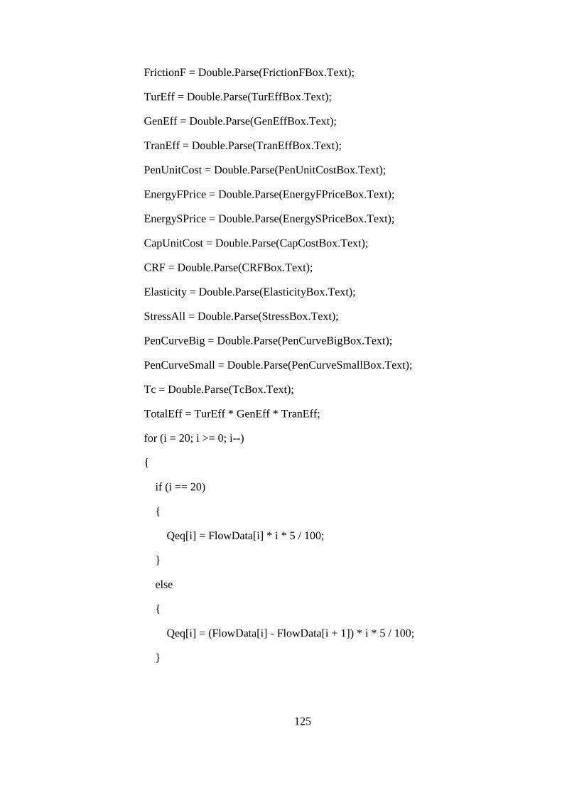
125
FrictionF = Double.Parse(FrictionFBox.Text);
TurEff = Double.Parse(TurEffBox.Text);
GenEff = Double.Parse(GenEffBox.Text);
TranEff = Double.Parse(TranEffBox.Text);
PenUnitCost = Double.Parse(PenUnitCostBox.Text);
EnergyFPrice = Double.Parse(EnergyFPriceBox.Text);
EnergySPrice = Double.Parse(EnergySPriceBox.Text);
CapUnitCost = Double.Parse(CapCostBox.Text);
CRF = Double.Parse(CRFBox.Text);
Elasticity = Double.Parse(ElasticityBox.Text);
StressAll = Double.Parse(StressBox.Text);
PenCurveBig = Double.Parse(PenCurveBigBox.Text);
PenCurveSmall = Double.Parse(PenCurveSmallBox.Text);
Tc = Double.Parse(TcBox.Text);
TotalEff = TurEff * GenEff * TranEff;
for (i = 20; i >= 0; i--)
{
if (i == 20)
{
Qeq[i] = FlowData[i] * i * 5 / 100;
}
else
{
Qeq[i] = (FlowData[i] - FlowData[i + 1]) * i * 5 / 100;
}

126
}
for (i = 0; i < 21; i++)
{
if (FlowData[i] == 0)
{
Diameter[i] = 0;
NetHead[i] = GrossHead;
Power[i] = 0;
PenThickness[i] = 0;
}
else
{
Diameter[i] = Math.Sqrt(4 * FlowData[i] / 0.125 / Math.PI /
Math.Sqrt(2 * g * GrossHead));
Diameter[i] = Math.Round(Diameter[i], 2);
PenThickness[i] = f_PenThick(Diameter[i], GrossHead, PenLen,
FlowData[i], FrictionF, StressAll, Elasticity, Tc);
NetHead[i] = f_NetHead(FlowData[i], PenLen, GrossHead, FrictionF,
Diameter[i]);
Power[i] = f_Power(FlowData[i], f_NetHead(FlowData[i], PenLen,
GrossHead, FrictionF, Diameter[i]), TotalEff);
}
}
for (k = 20; k >= 0; k--)
{
for (i = 20; i >= k; i--)
{

127
if (i == 20)
{
TEnergy[k] = f_Power(FlowData[i], f_NetHead(FlowData[i],
PenLen, GrossHead, FrictionF, Diameter[k]), TotalEff) * 8.76;
}
else
{
TEnergy[k] = TEnergy[k] + f_ME(Qeq[i], TotalEff,
f_NetHead(FlowData[i], PenLen, GrossHead, FrictionF, Diameter[k]));
}
if (i == 20 || i == 19)
{
FEnergy[k] = TEnergy[k];
}
}
}
for (i = 20; i >= 0; i--)
{
SEnergy[i] = TEnergy[i] - FEnergy[i];
}
for (i = 20; i >= 0; i--)
{
PenCost[i] = f_PenWeight(Diameter[i], PenThickness[i], PenLen) *
PenUnitCost * CRF;
CapCost[i] = Power[i] * CapUnitCost * CRF;
TotalCost[i] = CapCost[i] + PenCost[i];
Benefit[i] = (FEnergy[i] * EnergyFPrice + SEnergy[i] * EnergySPrice) *

128
Math.Pow(10, 6);
NetBenefit[i] = Benefit[i] - TotalCost[i];
}
for (i = 0; i < 21; i++)
{
FlowData[i] = Math.Round(FlowData[i], 2);
Diameter[i] = Math.Round(Diameter[i], 2);
NetHead[i] = Math.Round(NetHead[i], 2);
Power[i] = Math.Round(Power[i], 3);
FEnergy[i] = Math.Round(FEnergy[i], 3);
SEnergy[i] = Math.Round(SEnergy[i], 3);
TEnergy[i] = Math.Round(TEnergy[i], 3);
PenCost[i] = Math.Round(PenCost[i], 0);
CapCost[i] = Math.Round(CapCost[i], 0);
TotalCost[i] = Math.Round(TotalCost[i], 0);
Benefit[i] = Math.Round(Benefit[i], 0);
NetBenefit[i] = Math.Round(NetBenefit[i], 0);
}
for (i = 20; i >= 0; i--)
{
if (i == 20)
{
DsgnDischarge = FlowData[i];
NetHeadDsgn = NetHead[i];

129
PowerDsgn = Power[i];
FlowOccurPercent = i * 5;
PenDiaDsgn = Diameter[i];
FirmEnergy = FEnergy[i];
SecondaryEnergy = SEnergy[i];
TotalEnergy = TEnergy[i];
PenThickDsgn = PenThickness[i];
}
else if (NetBenefit[i] >= NetBenefit[i + 1])
{
DsgnDischarge = FlowData[i];
FlowOccurPercent = i * 5;
TotalEnergy = TEnergy[i];
PenDiaDsgn = Diameter[i];
PenThickDsgn = PenThickness[i];
}
}
if (DischargeCheckBox.Checked == true)
{
DsgnDischarge = Double.Parse(DsgnDischargeBox.Text);
}
PenDiaTrial = PenDiaDsgn; // Initial values for //
PenThickTrial = PenThickDsgn; // Penstock Optimization //
for (k = 0; k < 10; k++)
{

130
for (i = 20; i >= 0; i--)
{
if (i == 20 && DsgnDischarge >= FlowData[i])
{
TE = f_ME(Qeq[i], TotalEff, f_hf(FlowData[i], PenLen, FrictionF,
PenDiaTrial));
}
else if (DsgnDischarge >= FlowData[i])
{
TE = TE + f_ME(Qeq[i], TotalEff, f_hf(FlowData[i], PenLen,
FrictionF, PenDiaTrial));
}
else
{
EnergyLoss[k] = Math.Round(TE, 3);
TrialPenCost[k] = Math.Round(f_PenWeight(PenDiaTrial,
PenThickTrial, PenLen) * PenUnitCost * CRF, 0);
CostEnergyLoss[k] = Math.Round(TE * EnergySPrice *
Math.Pow(10, 6), 0);
TotalLossCost[k] = Math.Round(TrialPenCost[k] +
CostEnergyLoss[k], 0);
TrialPenDia[k] = PenDiaTrial;
TrialPenThick[k] = PenThickTrial;
PenDiaTrial = PenDiaTrial + 0.1;
PenThickTrial = f_PenThick(PenDiaTrial, GrossHead, PenLen,
DsgnDischarge, FrictionF, StressAll, Elasticity, Tc);
break;
}

131
}
}
for (k = 0; k < 10; k++)
{
if (k == 0)
{
PenDiaDsgn = TrialPenDia[k];
PenThickDsgn = TrialPenThick[k];
Ct = TotalLossCost[k];
}
else if (Ct >= TotalLossCost[k])
{
PenDiaDsgn = TrialPenDia[k];
PenThickDsgn = TrialPenThick[k];
Ct = TotalLossCost[k];
}
}
if (PenDiaCheckBox.Checked == true)
{
PenDiaDsgn = Double.Parse(PenDiaDsgnBox.Text);
PenThickDsgn = f_PenThick(PenDiaDsgn, GrossHead, PenLen,
DsgnDischarge, FrictionF, StressAll, Elasticity, Tc);
}
for (i = 20; i >= 0; i--)
{
if (i == 20 && DsgnDischarge >= FlowData[i])

132
{
TotalEnergy = f_ME(Qeq[i], TotalEff, f_NetHead(FlowData[i],
PenLen, GrossHead, FrictionF, PenDiaDsgn));
}
else if (DsgnDischarge >= FlowData[i])
{
TotalEnergy = TotalEnergy + f_ME(Qeq[i], TotalEff,
f_NetHead(FlowData[i], PenLen, GrossHead, FrictionF, PenDiaDsgn));
}
if (i == 20 || i == 19)
{
FirmEnergy = TotalEnergy;
}
if (DsgnDischarge < FlowData[i])
{
SecondaryEnergy = TotalEnergy - FirmEnergy;
break;
}
}
PowerDsgn = f_Power(DsgnDischarge, f_NetHead(DsgnDischarge, PenLen,
GrossHead, FrictionF, PenDiaDsgn), TotalEff);
NetHeadDsgn = f_NetHead(DsgnDischarge, PenLen, GrossHead, FrictionF,
PenDiaDsgn);
////////////////////////////////////////////////////////////////////////////////////////////////////////
//Module Decleration: Penstock Design Module //
//Note: The calculations for the decided penstock diameter are //
//carried out //

133
//Written by: EMIR ALIMOGLU //
//Date: 17.02.2011 //
/////////////////////////////////////////////////////////////////////////////////////////////////////
PenVel = f_Velocity(DsgnDischarge, f_area(PenDiaDsgn));
FrictionLoss = f_hf(DsgnDischarge, PenLen, FrictionF, PenDiaDsgn) +
f_vel_head(PenVel) * PenCurveSmall * 0.05 + f_vel_head(PenVel) * PenCurveBig
* 0.14;
WaveSpeed = f_WaveSpeed(PenDiaDsgn, PenThickDsgn, Elasticity);
DeltaHead = f_DeltaHead(WaveSpeed, PenVel, PenLen, Tc);
MaxHeadValve = GrossHead + DeltaHead - FrictionLoss;
Pc = 882500 * Math.Pow(PenThickDsgn / (PenDiaDsgn * 1000),3);
if (Pc <= 0.49)
{
AerDia = 7.47 * Math.Sqrt(DsgnDischarge / Math.Sqrt(Pc));
}
else
{
AerDia = 8.94 * Math.Sqrt(DsgnDischarge);
}
PenThickDsgn = PenThickDsgn + 2; //Corrosion
FirmEnergy = Math.Round(FirmEnergy, 2);
SecondaryEnergy = Math.Round(SecondaryEnergy, 2);
TotalEnergy = Math.Round(TotalEnergy, 2);
PowerDsgn = Math.Round(PowerDsgn, 2);
NetHeadDsgn = Math.Round(NetHeadDsgn, 2);
MaxHeadValve = Math.Round(MaxHeadValve, 2);

134
FrictionLoss = Math.Round(FrictionLoss, 2);
PenVel = Math.Round(PenVel, 2);
WaveSpeed = Math.Round(WaveSpeed, 2);
DeltaHead = Math.Round(DeltaHead, 2);
AerDia = Math.Round(AerDia, 2);
///////////////////////////////////////////////////////////////////////////////////////////////////
//Module Decleration: Forebay and Canal Design Module //
//Written by: EMIR ALIMOGLU //
//Date: 12.03.2012 //
//////////////////////////////////////////////////////////////////////////////////////////////////
ChanRough = Double.Parse(ChanRoughBox.Text);
PenEntElev = Double.Parse(PenEntElevBox.Text);
RVCoeff = Double.Parse(RVCoeffBox.Text);
ChanSSlope = Double.Parse(ChanSSlopeBox.Text);
ChanLen = Double.Parse(ChanLenBox.Text);
ChanSlope = Double.Parse(ChanSlopeBox.Text);
TurType = TurTypeBox.Text;
TurQuan = Int16.Parse(TurQuanBox.Text);
ChanWDepth = f_yBHS(DsgnDischarge, ChanRough, ChanSSlope,
ChanSlope);
ChanWidth = 2 * ChanWDepth * (Math.Sqrt(1 + Math.Pow(ChanSSlope,
2)) - ChanSSlope);
FRPen = PenVel / Math.Sqrt(g * PenDiaDsgn);
if (FRPen <= 0.25)
{
VortexH = 1.5 * PenDiaDsgn;

135
}
else
{
VortexH = (0.5 + 2 * FRPen) * PenDiaDsgn;
}
he = Math.Round(f_area(PenDiaDsgn) / CForCont / PenDiaDsgn,1);
ForStep = 0.3 * he;
ForBottomElev = PenEntElev - (he - PenDiaDsgn) / 2 - ForStep;
MinWL = PenEntElev + PenDiaDsgn / 2 + VortexH;
ReqVol = RVCoeff * DsgnDischarge;
TrashRackWidth = DsgnDischarge / TrashRackVel / (0.3 * he + VortexH +
he / 2);
ForebayWidth = TrashRackWidth + 1 + 2 * 0.3 * he;
ChanExitElev = MinWL - f_yQmanning(0.75 * DsgnDischarge / TurQuan,
ChanRough, ChanSSlope, ChanSlope, ChanWidth);
ChanExitWL = ChanExitElev + ChanWDepth;
ForSpillCrest = 0.1 + ChanExitWL;
do
{
ForebayLen = f_ForLen(DsgnDischarge, ReqVol, ForebayWidth,
ForSpillCrest, MinWL, 2);
if (ForebayLen / ForebayWidth > 3)
{
ForebayWidth = ForebayWidth + 1;
}
else
{

136
break;
}
} while (ForebayLen / ForebayWidth > 3);
ForH0 = f_Ho(DsgnDischarge,ForebayLen,2);
ForTopElev = ForSpillCrest + ForH0 + 0.1;
MaxWL = ForSpillCrest + ForH0;
NorWL = ChanExitWL;
ChanFreeboard = 0.2 * (ChanWDepth + 1);
NorWL = Math.Round(NorWL, 2);
MaxWL = Math.Round(MaxWL, 2);
TrashRackWidth = Math.Round(TrashRackWidth, 2);
ForSpillCrest = Math.Round(ForSpillCrest,2);
ForTopElev = Math.Round(ForTopElev, 2);
ForBottomElev = Math.Round(ForBottomElev, 2);
ForebayWidth = Math.Round(ForebayWidth, 1);
ForebayLen = Math.Round(ForebayLen, 1);
ChanWidth = Math.Round(ChanWidth, 2);
ChanWDepth = Math.Round(ChanWDepth, 2);
ChanExitElev = Math.Round(ChanExitElev, 2);
ChanExitWL = Math.Round(ChanExitWL, 2);
MinWL = Math.Round(MinWL, 2);
MaxWL = Math.Round(MaxWL, 2);
NorWL = Math.Round(NorWL, 2);
VortexH = Math.Round(VortexH, 2);
ChanFreeboard = Math.Round(ChanFreeboard, 2);

137
////////////////////////////////////////////////////////////////////////////////////////////////////
//Module Decleration: Diversion Weir Intake Design Module //
//Written by: EMIR ALIMOGLU //
//Date: 19.04.2011 //
///////////////////////////////////////////////////////////////////////////////////////////////////
PierNumber = Int16.Parse(PierNumberBox.Text);
PierThick = Double.Parse(PierThickBox.Text);
MaxSettDia = Double.Parse(MaxSettDiaBox.Text);
RemovalRatio = Double.Parse(RemovalRatioBox.Text);
Roughness = Double.Parse(RoughnessBox.Text);
DRack = Double.Parse(DRackBox.Text);
tRack = Double.Parse(tRackBox.Text);
PierIntakeThick = Double.Parse(PierIntakeThickBox.Text);
PierIntakeNumber = Int32.Parse(PierIntakeNumberBox.Text);
Kthalweg = Double.Parse(KthalwegBox.Text);
DuMax = Double.Parse(DuMaxBox.Text);
DuMin = Double.Parse(DuMinBox.Text);
DsuMax = Double.Parse(DsuMaxBox.Text);
DsuMin = Double.Parse(DsuMinBox.Text);
DsdMax = Double.Parse(DsdMaxBox.Text);
DsdMin = Double.Parse(DsdMinBox.Text);
Lspill = Double.Parse(LspillBox.Text);
Alpha = Double.Parse(AlphaBox.Text);
wsl = Double.Parse(wslBox.Text);
nsl = Int16.Parse(nslBox.Text);

138
dsl = Double.Parse(dslBox.Text);
tsl = Double.Parse(tslBox.Text);
Kr = Double.Parse(KrBox.Text);
Kd5 = Double.Parse(Kd5Box.Text);
Kd10 = Double.Parse(Kd10Box.Text);
Kd25 = Double.Parse(Kd25Box.Text);
Kd50 = Double.Parse(Kd50Box.Text);
Kd100 = Double.Parse(Kd100Box.Text);
Q5 = Double.Parse(Q5Box.Text);
Q10 = Double.Parse(Q10Box.Text);
Q25 = Double.Parse(Q25Box.Text);
Q50 = Double.Parse(Q50Box.Text);
Q100 = Double.Parse(Q100Box.Text);
if (BridgeCheckBox.Checked == true)
{
BridgePierNumber = Int16.Parse(BridgePierNumberBox.Text);
BridgePierThick = Double.Parse(BridgePierThickBox.Text);
Kp = Double.Parse(KpBox.Text);
Ka = Double.Parse(KaBox.Text);
}
else
{
BridgePierNumber = 0;
BridgePierThick = 0;
Kp = 0;

139
Ka = 0;
}
//Section 1-2
ChanEntElev = ChanExitElev + ChanSlope * ChanLen;
ChanEntWL = ChanEntElev + ChanWDepth;
IntakeDepths[0] = ChanWDepth;
IntakeWL[0] = ChanEntWL;
IntakeWidths[0] = ChanWidth;
IntakeWidths[1] = 2 * ChanWidth;
IntakeVelocity[0] = f_vel(DsgnDischarge, f_area(IntakeWidths[0],
IntakeDepths[0], ChanSSlope));
do
{
IntakeDepths[1] = f_depth_iter(DsgnDischarge, IntakeWidths[1],
IntakeWidths[0], IntakeDepths[0], ChanSSlope, CTransition);
IntakeVelocity[1] = f_vel(DsgnDischarge, f_area(IntakeWidths[1],
IntakeDepths[1], 0));
if (IntakeVelocity[0] < IntakeVelocity[1])
{
IntakeWidths[1] = IntakeWidths[1] + 0.1;
}
} while (IntakeVelocity[0] < IntakeVelocity[1]);
IntakeWL[1] = IntakeWL[0] + f_vel_head(IntakeVelocity[0]) + CTransition
* (f_vel_head(IntakeVelocity[0]) - f_vel_head(IntakeVelocity[1])) -
f_vel_head(IntakeVelocity[1]);
//Section 2-3
IntakeWidths[2] = IntakeWidths[1] - PierNumber * PierThick;
IntakeVelocity[2] = DsgnDischarge / IntakeWidths[2] / IntakeDepths[1];

140
HeadLossGate = Math.Pow(IntakeVelocity[2] / OrificeCoeff, 2) / 2 / g;
IntakeDepths[2] = f_vel_head(IntakeVelocity[1]) + IntakeDepths[1] +
HeadLossGate - f_vel_head(IntakeVelocity[2]);
IntakeWL[2] = IntakeWL[1] + f_vel_head(IntakeVelocity[1]) +
HeadLossGate - f_vel_head(IntakeVelocity[2]);
//Section 3-4
IntakeWidths[3] = IntakeWidths[2] + 1;
IntakeDepths[3] = f_depth_iter(DsgnDischarge, IntakeWidths[3],
IntakeWidths[2], IntakeDepths[2], 0, CSettContraction);
IntakeVelocity[3] = f_vel(DsgnDischarge, f_area(IntakeWidths[3],
IntakeWidths[3], 0));
HeadLossContraction = CSettContraction * (f_vel_head(IntakeVelocity[2]) -
f_vel_head(IntakeVelocity[3]));
IntakeWL[3] = IntakeWL[2] + f_vel_head(IntakeVelocity[2]) +
HeadLossContraction - f_vel_head(IntakeVelocity[3]);
//Section 4-5
if (MaxSettDia > 1)
{
a = 36;
}
else if (MaxSettDia < 1 && MaxSettDia > 0.1)
{
a = 44;
}
else
{
a = 51;
}

141
VMaxSett = (Math.Sqrt(MaxSettDia) * a) / 100;
IntakeWidths[4] = IntakeWidths[3];
SettUpStep = DsuMin;
do
{
IntakeDepths[4] = f_sett_depth(DsgnDischarge,
f_UpSill_loss(DsgnDischarge, IntakeWidths[4], IntakeDepths[3]), IntakeWidths[3],
IntakeWidths[4], IntakeDepths[3], SettUpStep);
IntakeVelocity[4] = f_vel(DsgnDischarge, f_area(IntakeWidths[4],
IntakeDepths[4], 0));
if (IntakeVelocity[4] > VMaxSett)
{
if (SettUpStep >= DsuMax)
{
IntakeWidths[4] = IntakeWidths[4] + 0.05;
IntakeWidths[3] = IntakeWidths[4];
IntakeDepths[3] = f_depth_iter(DsgnDischarge, IntakeWidths[3],
IntakeWidths[2], IntakeDepths[2], 0, CSettContraction);
IntakeVelocity[3] = f_vel(DsgnDischarge, f_area(IntakeWidths[3],
IntakeDepths[3], 0));
HeadLossContraction = CSettContraction *
(f_vel_head(IntakeVelocity[2]) - f_vel_head(IntakeVelocity[3]));
IntakeWL[3] = IntakeWL[2] + f_vel_head(IntakeVelocity[2]) +
HeadLossContraction - f_vel_head(IntakeVelocity[3]);
}
else
{
SettUpStep = SettUpStep + 0.05;
}

142
}
else
{
IntakeDepths[4] = f_sett_depth(DsgnDischarge,
f_UpSill_loss(DsgnDischarge, IntakeWidths[4], IntakeDepths[3]), IntakeWidths[3],
IntakeWidths[4], IntakeDepths[3], SettUpStep);
IntakeVelocity[4] = f_vel(DsgnDischarge, f_area(IntakeWidths[4],
IntakeDepths[4], 0));
break;
}
} while (IntakeVelocity[4] > VMaxSett);
if (MaxSettDia < 0.15)
{
SettVel = 663 * Math.Pow(MaxSettDia, 2);
}
else if (MaxSettDia > 1.5)
{
SettVel = 134.5 * Math.Sqrt(MaxSettDia);
}
else
{
SettVel = f_FallVel(MaxSettDia);
}
LSettBasin = (DsgnDischarge / (SettVel / 1000) / IntakeWidths[4]) + 2;
IntakeWL[4] = IntakeWL[3] + f_vel_head(IntakeVelocity[3]) +
f_UpSill_loss(DsgnDischarge, IntakeWidths[4], IntakeDepths[3]) -
f_vel_head(IntakeVelocity[4]);
//Section 5-6

143
IntakeWidths[5] = IntakeWidths[4];
IntakeDepths[5] = f_settbegin(DsgnDischarge, IntakeVelocity[4],
IntakeDepths[4], Roughness, LSettBasin, IntakeWidths[4], 0);
IntakeVelocity[5] = f_vel(DsgnDischarge, f_area(IntakeWidths[5],
IntakeDepths[5], 0));
IntakeWL[5] = IntakeWL[4] + f_vel_head(IntakeVelocity[4]) +
f_AvgFricSlope(IntakeVelocity[4], IntakeVelocity[5], IntakeDepths[5],
IntakeDepths[4], Roughness, IntakeWidths[4], 0) * LSettBasin -
f_vel_head(IntakeVelocity[5]);
//Section 6-7
IntakeWidths[6] = IntakeWidths[5];
IntakeWidths[7] = IntakeWidths[6] - PierIntakeNumber * PierIntakeThick;
SettDownStep = DsdMin;
do
{
IntakeDepths[6] = f_section7_depth(DsgnDischarge, IntakeVelocity[5],
IntakeDepths[5], IntakeWidths[6], SettDownStep);
IntakeVelocity[6] = f_vel(DsgnDischarge, f_area(IntakeWidths[6],
IntakeDepths[6], 0));
IntakeWL[6] = IntakeWL[5] + f_vel_head(IntakeVelocity[5]) + 0.02 -
f_vel_head(IntakeVelocity[6]);
//Section 7-8
IntakeVelocity[7] = DsgnDischarge / IntakeWidths[7] / IntakeDepths[6];
HeadLossGate2 = Math.Pow(IntakeVelocity[7] / OrificeCoeff, 2) / 2 / g;
IntakeDepths[7] = f_vel_head(IntakeVelocity[6]) + IntakeDepths[6] +
HeadLossGate2 - f_vel_head(IntakeVelocity[7]);
IntakeWL[7] = IntakeWL[6] + f_vel_head(IntakeVelocity[6]) +
HeadLossGate2 - f_vel_head(IntakeVelocity[7]);
//Section 8-9
nRack = (int) Math.Floor(IntakeWidths[7] / (DRack + tRack));

144
IntakeGrossArea = IntakeWidths[7] * IntakeDepths[6];
IntakeNetArea = (IntakeWidths[7] - nRack * tRack) * IntakeDepths[6];
HeadLossTrash = (1.45 - 0.45 * IntakeNetArea / IntakeGrossArea -
Math.Pow(IntakeNetArea / IntakeGrossArea, 2)) * f_vel_head(DsgnDischarge /
IntakeNetArea);
KcrestWL = IntakeWL[6] + f_vel_head(IntakeVelocity[6]) +
HeadLossGate2 + HeadLossTrash + f_UpSill_loss(DsgnDischarge,
IntakeWidths[7], IntakeDepths[7]) - f_vel_head(IntakeVelocity[7]);
IntakeStep = KcrestWL - Kthalweg - IntakeDepths[7] - HeadLossTrash;
if (IntakeStep < DuMin)
{
SettDownStep = SettDownStep + 0.05;
}
else if (IntakeStep > DuMax)
{
SettDownStep = SettDownStep - 0.05;
}
} while (IntakeStep < DuMin || IntakeStep > DuMax);
for (i = 0; i < 8; i++)
{
IntakeEGL[i] = IntakeWL[i] + f_vel_head(IntakeVelocity[i]);
}
Kcrest = KcrestWL + 0.10;
Lsluice = nsl * wsl + (nsl - 1) * tsl;
//////////////////////////////////////////////////////////////////////////////////////////////////
//Module Decleration: Energy Dissipator Design Module //
//Written by: EMIR ALIMOGLU //

145
//Date: 22.08.2011 //
////////////////////////////////////////////////////////////////////////////////////////////////
// 100 years frequency
K100 = f_Ki(Q100, Lspill, wsl, Kd100, Kr, Kcrest, Kthalweg, Alpha, nsl,
dsl, tsl, BridgePierNumber, BridgePierThick, Kp, Ka);
Qspill100 = f_QSpill(K100, Kthalweg, Q100, Lspill, wsl, Kr, Kcrest, Kd100,
Alpha, nsl, dsl, tsl, BridgePierNumber, BridgePierThick, Kp, Ka);
Qsluice100 = f_QSluice(K100, Kthalweg, wsl, nsl, dsl);
ha100 = Math.Pow(Q100 / (K100 - Kthalweg) / (Lsluice + Lspill), 2) / 2 / g;
Eu100 = K100 + ha100;
EDSpillDepths100[2] = Kd100 - Kr;
E3s100 = EDSpillDepths100[2] + f_vel_head(f_vel(Qspill100, f_area(Lspill,
EDSpillDepths100[2], 0))) + Kr;
DeltaEs100 = Eu100 - E3s100;
EDSpillDepths100[0] = f_hydjumpy1(Qspill100, Lspill, DeltaEs100);
EDSpillDepths100[1] = f_hydjumpsequent(Qspill100, Lspill,
EDSpillDepths100[0]);
SpillwaySill100 = EDSpillDepths100[1] + f_vel_head(f_vel(Qspill100,
f_area(Lspill, EDSpillDepths100[1], 0))) - EDSpillDepths100[2] +
f_vel_head(f_vel(Qspill100, f_area(Lspill, EDSpillDepths100[2], 0)));
LEDSpill100 = f_BasinLength(f_BasinType(f_Froude(Qspill100, Lspill,
EDSpillDepths100[0], 0), f_vel(Qspill100, f_area(Lspill, EDSpillDepths100[0],
0))), EDSpillDepths100[1]);
EDSluiceDepths100[2] = EDSpillDepths100[2];
E3sl100 = EDSluiceDepths100[2] + f_vel_head(f_vel(Qsluice100,
f_area(Lsluice, EDSluiceDepths100[2], 0))) + Kr;
DeltaEsl100 = Eu100 - E3sl100;
EDSluiceDepths100[0] = f_hydjumpy1(Qsluice100, Lsluice, DeltaEsl100);
EDSluiceDepths100[1] = f_hydjumpsequent(Qsluice100, Lsluice,
EDSluiceDepths100[0]);

146
SluiceSill100 = EDSluiceDepths100[1] + f_vel_head(f_vel(Qsluice100,
f_area(Lsluice, EDSluiceDepths100[1], 0))) - EDSluiceDepths100[2] +
f_vel_head(f_vel(Qsluice100, f_area(Lsluice, EDSluiceDepths100[2], 0)));
LEDSluice100 = f_BasinLength(f_BasinType(f_Froude(Qsluice100,
Lsluice, EDSluiceDepths100[0], 0), f_vel(Qsluice100, f_area(Lsluice,
EDSluiceDepths100[0], 0))), EDSluiceDepths100[1]);
// 50 years frequency
K50 = f_Ki(Q50, Lspill, wsl, Kd50, Kr, Kcrest, Kthalweg, Alpha, nsl, dsl,
tsl, BridgePierNumber, BridgePierThick, Kp, Ka);
Qspill50 = f_QSpill(K50, Kthalweg, Q50, Lspill, wsl, Kr, Kcrest, Kd50,
Alpha, nsl, dsl, tsl, BridgePierNumber, BridgePierThick, Kp, Ka);
Qsluice50 = f_QSluice(K50, Kthalweg, wsl, nsl, dsl);
ha50 = Math.Pow(Q50 / (K50 - Kthalweg) / (Lsluice + Lspill), 2) / 2 / g;
Eu50 = K50 + ha50;
EDSpillDepths50[2] = Kd50 - Kr;
E3s50 = EDSpillDepths50[2] + f_vel_head(f_vel(Qspill50, f_area(Lspill,
EDSpillDepths50[2], 0))) + Kr;
DeltaEs50 = Eu50 - E3s50;
EDSpillDepths50[0] = f_hydjumpy1(Qspill50, Lspill, DeltaEs50);
EDSpillDepths50[1] = f_hydjumpsequent(Qspill50, Lspill,
EDSpillDepths50[0]);
SpillwaySill50 = EDSpillDepths50[1] + f_vel_head(f_vel(Qspill50,
f_area(Lspill, EDSpillDepths50[1], 0))) - EDSpillDepths50[2] +
f_vel_head(f_vel(Qspill50, f_area(Lspill, EDSpillDepths50[2], 0)));
LEDSpill50 = f_BasinLength(f_BasinType(f_Froude(Qspill50, Lspill,
EDSpillDepths50[0], 0), f_vel(Qspill50, f_area(Lspill, EDSpillDepths50[0], 0))),
EDSpillDepths50[1]);
EDSluiceDepths50[2] = EDSpillDepths50[2];
E3sl50 = EDSluiceDepths50[2] + f_vel_head(f_vel(Qsluice50,
f_area(Lsluice, EDSluiceDepths50[2], 0))) + Kr;
DeltaEsl50 = Eu50 - E3sl50;

147
EDSluiceDepths50[0] = f_hydjumpy1(Qsluice50, Lsluice, DeltaEsl50);
EDSluiceDepths50[1] = f_hydjumpsequent(Qsluice50, Lsluice,
EDSluiceDepths50[0]);
SluiceSill50 = EDSluiceDepths50[1] + f_vel_head(f_vel(Qsluice50,
f_area(Lsluice, EDSluiceDepths50[1], 0))) - EDSluiceDepths50[2] +
f_vel_head(f_vel(Qsluice50, f_area(Lsluice, EDSluiceDepths50[2], 0)));
LEDSluice50 = f_BasinLength(f_BasinType(f_Froude(Qsluice50, Lsluice,
EDSluiceDepths50[0], 0), f_vel(Qsluice50, f_area(Lsluice, EDSluiceDepths50[0],
0))), EDSluiceDepths50[1]);
// 25 years frequency
K25 = f_Ki(Q25, Lspill, wsl, Kd25, Kr, Kcrest, Kthalweg, Alpha, nsl, dsl,
tsl, BridgePierNumber, BridgePierThick, Kp, Ka);
Qspill25 = f_QSpill(K25, Kthalweg, Q25, Lspill, wsl, Kr, Kcrest, Kd25,
Alpha, nsl, dsl, tsl, BridgePierNumber, BridgePierThick, Kp, Ka);
Qsluice25 = f_QSluice(K25, Kthalweg, wsl, nsl, dsl);
ha25 = Math.Pow(Q25 / (K25 - Kthalweg) / (Lsluice + Lspill), 2) / 2 / g;
Eu25 = K25 + ha25;
EDSpillDepths25[2] = Kd25 - Kr;
E3s25 = EDSpillDepths25[2] + f_vel_head(f_vel(Qspill25, f_area(Lspill,
EDSpillDepths25[2], 0))) + Kr;
DeltaEs25 = Eu25 - E3s25;
EDSpillDepths25[0] = f_hydjumpy1(Qspill25, Lspill, DeltaEs25);
EDSpillDepths25[1] = f_hydjumpsequent(Qspill25, Lspill,
EDSpillDepths25[0]);
SpillwaySill25 = EDSpillDepths25[1] + f_vel_head(f_vel(Qspill25,
f_area(Lspill, EDSpillDepths25[1], 0))) - EDSpillDepths25[2] +
f_vel_head(f_vel(Qspill25, f_area(Lspill, EDSpillDepths25[2], 0)));
LEDSpill25 = f_BasinLength(f_BasinType(f_Froude(Qspill25, Lspill,
EDSpillDepths25[0], 0), f_vel(Qspill25, f_area(Lspill, EDSpillDepths25[0], 0))),
EDSpillDepths25[1]);
EDSluiceDepths25[2] = EDSpillDepths25[2];

148
E3sl25 = EDSluiceDepths25[2] + f_vel_head(f_vel(Qsluice25,
f_area(Lsluice, EDSluiceDepths25[2], 0))) + Kr;
DeltaEsl25 = Eu25 - E3sl25;
EDSluiceDepths25[0] = f_hydjumpy1(Qsluice25, Lsluice, DeltaEsl25);
EDSluiceDepths25[1] = f_hydjumpsequent(Qsluice25, Lsluice,
EDSluiceDepths25[0]);
SluiceSill25 = EDSluiceDepths25[1] + f_vel_head(f_vel(Qsluice25,
f_area(Lsluice, EDSluiceDepths25[1], 0))) - EDSluiceDepths25[2] +
f_vel_head(f_vel(Qsluice25, f_area(Lsluice, EDSluiceDepths25[2], 0)));
LEDSluice25 = f_BasinLength(f_BasinType(f_Froude(Qsluice25, Lsluice,
EDSluiceDepths25[0], 0), f_vel(Qsluice25, f_area(Lsluice, EDSluiceDepths25[0],
0))), EDSluiceDepths25[1]);
// 10 years frequency
K10 = f_Ki(Q10, Lspill, wsl, Kd10, Kr, Kcrest, Kthalweg, Alpha, nsl, dsl,
tsl, BridgePierNumber, BridgePierThick, Kp, Ka);
Qspill10 = f_QSpill(K10, Kthalweg, Q10, Lspill, wsl, Kr, Kcrest, Kd10,
Alpha, nsl, dsl, tsl, BridgePierNumber, BridgePierThick, Kp, Ka);
Qsluice10 = f_QSluice(K10, Kthalweg, wsl, nsl, dsl);
ha10 = Math.Pow(Q10 / (K10 - Kthalweg) / (Lsluice + Lspill), 2) / 2 / g;
Eu10 = K10 + ha10;
EDSpillDepths10[2] = Kd10 - Kr;
E3s10 = EDSpillDepths10[2] + f_vel_head(f_vel(Qspill10, f_area(Lspill,
EDSpillDepths10[2], 0))) + Kr;
DeltaEs10 = Eu10 - E3s10;
EDSpillDepths10[0] = f_hydjumpy1(Qspill10, Lspill, DeltaEs10);
EDSpillDepths10[1] = f_hydjumpsequent(Qspill10, Lspill,
EDSpillDepths10[0]);
SpillwaySill10 = EDSpillDepths10[1] + f_vel_head(f_vel(Qspill10,
f_area(Lspill, EDSpillDepths10[1], 0))) - EDSpillDepths10[2] +
f_vel_head(f_vel(Qspill10, f_area(Lspill, EDSpillDepths10[2], 0)));
LEDSpill10 = f_BasinLength(f_BasinType(f_Froude(Qspill10, Lspill,

149
EDSpillDepths10[0], 0), f_vel(Qspill10, f_area(Lspill, EDSpillDepths10[0], 0))),
EDSpillDepths10[1]);
EDSluiceDepths10[2] = EDSpillDepths10[2];
E3sl10 = EDSluiceDepths10[2] + f_vel_head(f_vel(Qsluice10,
f_area(Lsluice, EDSluiceDepths10[2], 0))) + Kr;
DeltaEsl10 = Eu10 - E3sl10;
EDSluiceDepths10[0] = f_hydjumpy1(Qsluice10, Lsluice, DeltaEsl10);
EDSluiceDepths10[1] = f_hydjumpsequent(Qsluice10, Lsluice,
EDSluiceDepths10[0]);
SluiceSill10 = EDSluiceDepths10[1] + f_vel_head(f_vel(Qsluice10,
f_area(Lsluice, EDSluiceDepths10[1], 0))) - EDSluiceDepths10[2] +
f_vel_head(f_vel(Qsluice10, f_area(Lsluice, EDSluiceDepths10[2], 0)));
LEDSluice10 = f_BasinLength(f_BasinType(f_Froude(Qsluice10, Lsluice,
EDSluiceDepths10[0], 0), f_vel(Qsluice10, f_area(Lsluice, EDSluiceDepths10[0],
0))), EDSluiceDepths10[1]);
// 5 years frequency
K5 = f_Ki(Q5, Lspill, wsl, Kd5, Kr, Kcrest, Kthalweg, Alpha, nsl, dsl, tsl,
BridgePierNumber, BridgePierThick, Kp, Ka);
Qspill5 = f_QSpill(K5, Kthalweg, Q5, Lspill, wsl, Kr, Kcrest, Kd5, Alpha,
nsl, dsl, tsl, BridgePierNumber, BridgePierThick, Kp, Ka);
Qsluice5 = f_QSluice(K5, Kthalweg, wsl, nsl, dsl);
ha5 = Math.Pow(Q5 / (K5 - Kthalweg) / (Lsluice + Lspill), 2) / 2 / g;
Eu5 = K5 + ha5;
EDSpillDepths5[2] = Kd5 - Kr;
E3s5 = EDSpillDepths5[2] + f_vel_head(f_vel(Qspill5, f_area(Lspill,
EDSpillDepths5[2], 0))) + Kr;
DeltaEs5 = Eu5 - E3s5;
EDSpillDepths5[0] = f_hydjumpy1(Qspill5, Lspill, DeltaEs5);
EDSpillDepths5[1] = f_hydjumpsequent(Qspill5, Lspill,
EDSpillDepths5[0]);
SpillwaySill5 = EDSpillDepths5[1] + f_vel_head(f_vel(Qspill5,

150
f_area(Lspill, EDSpillDepths5[1], 0))) - EDSpillDepths5[2] +
f_vel_head(f_vel(Qspill5, f_area(Lspill, EDSpillDepths5[2], 0)));
LEDSpill5 = f_BasinLength(f_BasinType(f_Froude(Qspill5, Lspill,
EDSpillDepths5[0], 0), f_vel(Qspill5, f_area(Lspill, EDSpillDepths5[0], 0))),
EDSpillDepths5[1]);
EDSluiceDepths5[2] = EDSpillDepths5[2];
E3sl5 = EDSluiceDepths5[2] + f_vel_head(f_vel(Qsluice5, f_area(Lsluice,
EDSluiceDepths5[2], 0))) + Kr;
DeltaEsl5 = Eu5 - E3sl5;
EDSluiceDepths5[0] = f_hydjumpy1(Qsluice5, Lsluice, DeltaEsl5);
EDSluiceDepths5[1] = f_hydjumpsequent(Qsluice5, Lsluice,
EDSluiceDepths5[0]);
SluiceSill5 = EDSluiceDepths5[1] + f_vel_head(f_vel(Qsluice5,
f_area(Lsluice, EDSluiceDepths5[1], 0))) - EDSluiceDepths5[2] +
f_vel_head(f_vel(Qsluice5, f_area(Lsluice, EDSluiceDepths5[2], 0)));
LEDSluice5 = f_BasinLength(f_BasinType(f_Froude(Qsluice5, Lsluice,
EDSluiceDepths5[0], 0), f_vel(Qsluice5, f_area(Lsluice, EDSluiceDepths5[0], 0))),
EDSluiceDepths5[1]);
//Searching the worst hydraulic conditions for spillway section
LEDSpill = LEDSpill5;
SpillwaySill = SpillwaySill5;
Qspill = Qspill5;
EDSpilly1 = EDSpillDepths5[0];
EDSpilly2 = EDSpillDepths5[1];
if (LEDSpill <= LEDSpill10)
{
LEDSpill = LEDSpill10;
SpillwaySill = SpillwaySill10;
Qspill = Qspill10;
EDSpilly1 = EDSpillDepths10[0];
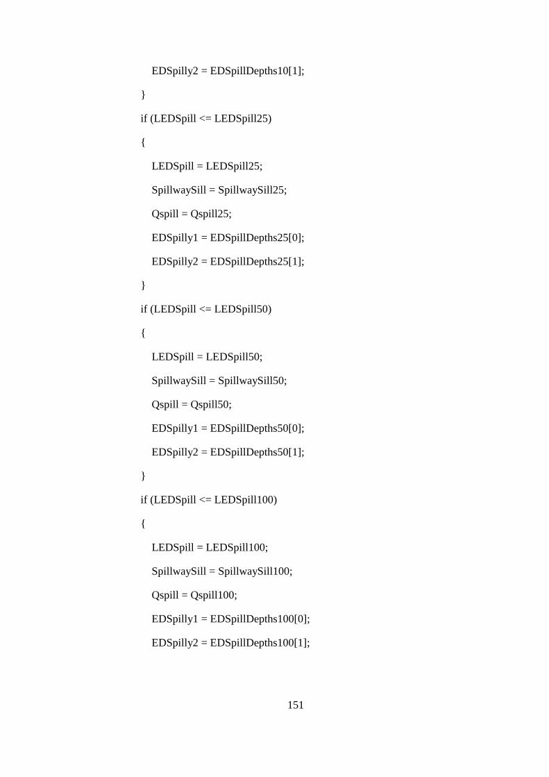
151
EDSpilly2 = EDSpillDepths10[1];
}
if (LEDSpill <= LEDSpill25)
{
LEDSpill = LEDSpill25;
SpillwaySill = SpillwaySill25;
Qspill = Qspill25;
EDSpilly1 = EDSpillDepths25[0];
EDSpilly2 = EDSpillDepths25[1];
}
if (LEDSpill <= LEDSpill50)
{
LEDSpill = LEDSpill50;
SpillwaySill = SpillwaySill50;
Qspill = Qspill50;
EDSpilly1 = EDSpillDepths50[0];
EDSpilly2 = EDSpillDepths50[1];
}
if (LEDSpill <= LEDSpill100)
{
LEDSpill = LEDSpill100;
SpillwaySill = SpillwaySill100;
Qspill = Qspill100;
EDSpilly1 = EDSpillDepths100[0];
EDSpilly2 = EDSpillDepths100[1];
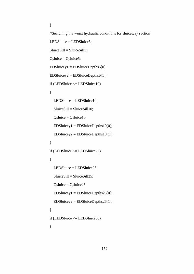
152
}
//Searching the worst hydraulic conditions for sluiceway section
LEDSluice = LEDSluice5;
SluiceSill = SluiceSill5;
Qsluice = Qsluice5;
EDSluicey1 = EDSluiceDepths5[0];
EDSluicey2 = EDSluiceDepths5[1];
if (LEDSluice <= LEDSluice10)
{
LEDSluice = LEDSluice10;
SluiceSill = SluiceSill10;
Qsluice = Qsluice10;
EDSluicey1 = EDSluiceDepths10[0];
EDSluicey2 = EDSluiceDepths10[1];
}
if (LEDSluice <= LEDSluice25)
{
LEDSluice = LEDSluice25;
SluiceSill = SluiceSill25;
Qsluice = Qsluice25;
EDSluicey1 = EDSluiceDepths25[0];
EDSluicey2 = EDSluiceDepths25[1];
}
if (LEDSluice <= LEDSluice50)
{
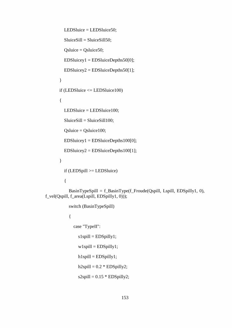
153
LEDSluice = LEDSluice50;
SluiceSill = SluiceSill50;
Qsluice = Qsluice50;
EDSluicey1 = EDSluiceDepths50[0];
EDSluicey2 = EDSluiceDepths50[1];
}
if (LEDSluice <= LEDSluice100)
{
LEDSluice = LEDSluice100;
SluiceSill = SluiceSill100;
Qsluice = Qsluice100;
EDSluicey1 = EDSluiceDepths100[0];
EDSluicey2 = EDSluiceDepths100[1];
}
if (LEDSpill >= LEDSluice)
{
BasinTypeSpill = f_BasinType(f_Froude(Qspill, Lspill, EDSpilly1, 0),
f_vel(Qspill, f_area(Lspill, EDSpilly1, 0)));
switch (BasinTypeSpill)
{
case "TypeII":
s1spill = EDSpilly1;
w1spill = EDSpilly1;
h1spill = EDSpilly1;
h2spill = 0.2 * EDSpilly2;
s2spill = 0.15 * EDSpilly2;

154
w2spill = 0.15 * EDSpilly2;
s3spill = 0;
w3spill = 0;
h3spill = 0;
h4spill = 0;
break;
case "TypeIII":
s1spill = EDSpilly1;
w1spill = EDSpilly1;
h1spill = EDSpilly1;
h3spill = EDSpilly1 * (4 + f_Froude(Qspill, Lspill, EDSpilly1, 0))
/ 6;
h4spill = EDSpilly1 * (9 + f_Froude(Qspill, Lspill, EDSpilly1, 0))
/ 9;
s3spill = 0.75 * h3spill;
w3spill = 0.75 * h3spill;
h2spill = 0;
s2spill = 0;
w2spill = 0;
break;
case "TypeIV":
s1spill = 0;
w1spill = 0;
h1spill = 0;
h3spill = 0;
h4spill = EDSpilly1 * (9 + f_Froude(Qspill, Lspill, EDSpilly1, 0))
/ 9;

155
s3spill = 0;
w3spill = 0;
h2spill = 0;
s2spill = 0;
w2spill = 0;
break;
case "Type N/A":
s1spill = 0;
w1spill = 0;
h1spill = 0;
h3spill = 0;
h4spill = 0;
s3spill = 0;
w3spill = 0;
h2spill = 0;
s2spill = 0;
w2spill = 0;
break;
}
LEDSluice = LEDSpill;
BasinTypeSluice = BasinTypeSpill;
s1sluice = s1spill;
w1sluice = w1spill;
h1sluice = h1spill;
h3sluice = h3spill;

156
h4sluice = h4spill;
s3sluice = s3spill;
w3sluice = w3spill;
h2sluice = h2spill;
s2sluice = s2spill;
w2sluice = w2spill;
}
else
{
BasinTypeSluice = f_BasinType(f_Froude(Qsluice, Lsluice,
EDSluicey1, 0), f_vel(Qsluice, f_area(Lsluice, EDSluicey1, 0)));
switch (BasinTypeSluice)
{
case "TypeII":
s1sluice = EDSluicey1;
w1sluice = EDSluicey1;
h1sluice = EDSluicey1;
h2sluice = 0.2 * EDSluicey2;
s2sluice = 0.15 * EDSluicey2;
w2sluice = 0.15 * EDSluicey2;
s3sluice = 0;
w3sluice = 0;
h3sluice = 0;
h4sluice = 0;
break;
case "TypeIII":

157
s1sluice = EDSluicey1;
w1sluice = EDSluicey1;
h1sluice = EDSluicey1;
h3sluice = EDSluicey1 * (4 + f_Froude(Qsluice, Lsluice,
EDSluicey1, 0)) / 6;
h4sluice = EDSluicey1 * (9 + f_Froude(Qsluice, Lsluice,
EDSluicey1, 0)) / 9;
s3sluice = 0.75 * h3sluice;
w3sluice = 0.75 * h3sluice;
h2sluice = 0;
s2sluice = 0;
w2sluice = 0;
break;
case "TypeIV":
s1sluice = 0;
w1sluice = 0;
h1sluice = 0;
h3sluice = 0;
h4sluice = EDSluicey1 * (9 + f_Froude(Qsluice, Lsluice,
EDSluicey1, 0)) / 9;
s3sluice = 0;
w3sluice = 0;
h2sluice = 0;
s2sluice = 0;
w2sluice = 0;
break;
case "Type N/A":

158
s1sluice = 0;
w1sluice = 0;
h1sluice = 0;
h3sluice = 0;
h4sluice = 0;
s3sluice = 0;
w3sluice = 0;
h2sluice = 0;
s2sluice = 0;
w2sluice = 0;
break;
}
LEDSpill = LEDSluice;
BasinTypeSpill = BasinTypeSluice;
s1spill = s1sluice;
w1spill = w1sluice;
h1spill = h1sluice;
h3spill = h3sluice;
h4spill = h4sluice;
s3spill = s3sluice;
w3spill = w3sluice;
h2spill = h2sluice;
s2spill = s2sluice;
w2spill = w2sluice;
}

159
for (i = 0; i < 8; i++)
{
IntakeDepths[i] = Math.Round(IntakeDepths[i], 3);
IntakeVelocity[i] = Math.Round(IntakeVelocity[i], 3);
IntakeWidths[i] = Math.Round(IntakeWidths[i], 3);
IntakeWL[i] = Math.Round(IntakeWL[i], 3);
IntakeEGL[i] = Math.Round(IntakeEGL[i], 3);
}
FR1Spill = f_Froude(Qspill, Lspill, EDSpilly1, 0);
U1Spill = f_vel(Qspill, f_area(Lspill, EDSpilly1, 0));
FR1Sluice = f_Froude(Qsluice, Lsluice, EDSluicey1, 0);
U1Sluice = f_vel(Qsluice, f_area(Lsluice, EDSluicey1, 0));
s1spill = Math.Round(s1spill, 1);
s2spill = Math.Round(s2spill, 1);
s3spill = Math.Round(s3spill, 1);
w1spill = Math.Round(w1spill, 1);
w2spill = Math.Round(w2spill, 1);
w3spill = Math.Round(w3spill, 1);
h1spill = Math.Round(h1spill, 1);
h2spill = Math.Round(h2spill, 1);
h3spill = Math.Round(h3spill, 1);
h4spill = Math.Round(h4spill, 1);
s1sluice = Math.Round(s1sluice, 1);
s2sluice = Math.Round(s2sluice, 1);
s3sluice = Math.Round(s3sluice, 1);

160
w1sluice = Math.Round(w1sluice, 1);
w2sluice = Math.Round(w2sluice, 1);
w3sluice = Math.Round(w3sluice, 1);
h1sluice = Math.Round(h1sluice, 1);
h2sluice = Math.Round(h2sluice, 1);
h3sluice = Math.Round(h3sluice, 1);
h4sluice = Math.Round(h4sluice, 1);
LEDSluice = Math.Round(LEDSluice, 1);
LEDSpill = Math.Round(LEDSpill, 1);
EDSluicey1 = Math.Round(EDSluicey1, 2);
EDSluicey2 = Math.Round(EDSluicey2, 2);
EDSpilly1 = Math.Round(EDSpilly1, 2);
EDSpilly2 = Math.Round(EDSpilly2, 2);
FR1Spill = Math.Round(FR1Spill, 2);
U1Spill = Math.Round(U1Spill, 2);
FR1Sluice = Math.Round(FR1Sluice, 2);
U1Sluice = Math.Round(U1Sluice, 2);
Kcrest = Math.Round(Kcrest, 3);
SettDownStep = Math.Round(SettDownStep, 2);
SettUpStep = Math.Round(SettUpStep, 2);
IntakeStep = Math.Round(IntakeStep, 2);
K100 = Math.Round(K100, 2);
LSettBasin = Math.Round(LSettBasin, 2);
Qspill = Math.Round(Qspill,2);
Qsluice = Math.Round(Qsluice,2);

161
Qspill100 = Math.Round(Qspill100, 2);
Qsluice100 = Math.Round(Qsluice100, 2);
ChanEntElev = Math.Round(ChanEntElev, 2);
RunCondition = true; //Indicating the Run Button clicked and calculations
completed successfully
}
}
}
}
//////////////////////////////////////////////////////////////////////////////////////////////////////
//Form Decleration: Form 2: Installed Capacity Optimzation Output //
//Window //
/////////////////////////////////////////////////////////////////////////////////////////////////////
namespace WindowsFormsApplication1
{
public partial class Form2 : Form
{
public Form2()
{
InitializeComponent();
}
int i;
private void Form2_Load(object sender, EventArgs e)
{
if (Form1.RunCondition)
{

162
OptTable.Rows.Clear();
for (i = 20; i >= 0; i--)
{
OptTable.Rows.Add(i*5,Form1.FlowData[i], Form1.Diameter[i],
Form1.PenThickness[i], Form1.NetHead[i], Form1.Power[i], Form1.FEnergy[i],
Form1.SEnergy[i], Form1.TEnergy[i], Form1.PenCost[i].ToString("#,##0"),
Form1.CapCost[i].ToString("#,##0"), Form1.TotalCost[i].ToString("#,##0"),
Form1.Benefit[i].ToString("#,##0"), Form1.NetBenefit[i].ToString("#,##0"));
}
for (i = 0; i < 21; i++)
{
if (Form1.DsgnDischarge == Form1.FlowData[i])
{
OptTable.Rows[20-i].DefaultCellStyle.BackColor = Color.Aqua;
break;
}
}
FlowOccurPercentLabel.Text = Form1.FlowOccurPercent.ToString();
OptDisLabel.Text = Form1.DsgnDischarge.ToString();
FEnergyLabel.Text = Form1.FirmEnergy.ToString();
SEnergyLabel.Text = Form1.SecondaryEnergy.ToString();
TEnergyLabel.Text = Form1.TotalEnergy.ToString();
PenDiaLabel.Text = Form1.PenDiaDsgn.ToString();
PowerLabel.Text = Form1.PowerDsgn.ToString();
NetHeadLabel.Text = Form1.NetHeadDsgn.ToString();
}

163
}
private void CapOptGraphButton_Click(object sender, EventArgs e)
{
Form9 CapOptGraph = new Form9();
CapOptGraph.Show();
}
}
}
////////////////////////////////////////////////////////////////////////////////////////////////////////
//Form Decleration: Form 3: Penstock Diameter Optimzation Output //
//Window //
//////////////////////////////////////////////////////////////////////////////////////////////////////
namespace WindowsFormsApplication1
{
public partial class Form3 : Form
{
public Form3()
{
InitializeComponent();
}
int k;
private void Form3_Load(object sender, EventArgs e)
{
if (Form1.RunCondition)
{

164
PenOptTable.Rows.Clear();
for (k = 0; k < 10; k++)
{
PenOptTable.Rows.Add(Form1.TrialPenDia[k],
Form1.TrialPenThick[k], Form1.TrialPenCost[k].ToString("#,##0"),
Form1.EnergyLoss[k], Form1.CostEnergyLoss[k].ToString("#,##0"),
Form1.TotalLossCost[k].ToString("#,##0"));
}
for (k = 0; k < 10; k++)
{
if (Form1.PenDiaDsgn == Form1.TrialPenDia[k])
{
PenOptTable.Rows[k].DefaultCellStyle.BackColor = Color.Aqua;
break;
}
}
FlowOccurPercentLabel.Text = Form1.FlowOccurPercent.ToString();
OptDisLabel.Text = Form1.DsgnDischarge.ToString();
FEnergyLabel.Text = Form1.FirmEnergy.ToString();
SEnergyLabel.Text = Form1.SecondaryEnergy.ToString();
TEnergyLabel.Text = Form1.TotalEnergy.ToString();
PenDiaLabel.Text = Form1.PenDiaDsgn.ToString();
PowerLabel.Text = Form1.PowerDsgn.ToString();
NetHeadLabel.Text = Form1.NetHeadDsgn.ToString();
}
}
private void button1_Click(object sender, EventArgs e)

165
{
Form10 PenOptGraph = new Form10();
PenOptGraph.Show();
}
}
}
///////////////////////////////////////////////////////////////////////////////////////////////////////
//Form Decleration: Form 4: Intake Charactersitics Output Window //
//////////////////////////////////////////////////////////////////////////////////////////////////////
namespace WindowsFormsApplication1
{
public partial class Form4 : Form
{
public Form4()
{
InitializeComponent();
}
int i;
bool boolIntake = true;
private void Form4_Load(object sender, EventArgs e)
{
if (Form1.RunCondition)
{
for (i = 0; i < 8; i++)
{

166
IntakeOutTbl.Rows.Add(i + 1, Form1.IntakeWidths[i],
Form1.IntakeDepths[i], Form1.IntakeWL[i], Form1.IntakeVelocity[i],
Form1.IntakeEGL[i]);
}
CrestLabel.Text = Form1.Kcrest.ToString();
SettDownStepLabel.Text = Form1.SettDownStep.ToString();
SettUpStepLabel.Text = Form1.SettUpStep.ToString();
IntakeStepLabel.Text = Form1.IntakeStep.ToString();
K100Label.Text = Form1.K100.ToString();
LSettBasinLabel.Text = Form1.LSettBasin.ToString();
QsluiceLabel.Text = Form1.Qsluice100.ToString();
QspillLabel.Text = Form1.Qspill100.ToString();
}
}
private void IntakeImageButton_Click(object sender, EventArgs e)
{
if (boolIntake == true)
{
IntakeImagePB.Image =
WindowsFormsApplication1.Properties.Resources.IntakePlan;
IntakeImageButton.Text = "View Intake Profile";
boolIntake = false;
}
else
{
IntakeImagePB.Image =
WindowsFormsApplication1.Properties.Resources.IntakeProfile;

167
IntakeImageButton.Text = "View Intake Plan";
boolIntake = true;
}
}
}
}
/////////////////////////////////////////////////////////////////////////////////////////////////////////////
//Form Decleration: Form 5: Energy Dissipators Design Output Window //
////////////////////////////////////////////////////////////////////////////////////////////////////////////
namespace WindowsFormsApplication1
{
public partial class Form5 : Form
{
public Form5()
{
InitializeComponent();
}
private void Form5_Load(object sender, EventArgs e)
{
if (Form1.RunCondition)
{
BasinTypeSluiceLabel.Text = Form1.BasinTypeSluice;
if (Form1.BasinTypeSpill == "TypeII")
{
pictureBox1.Image =
WindowsFormsApplication1.Properties.Resources.USBRTypeIIBasin;

168
label40.Visible = false;
h4SpillLabel.Visible = false;
label8.Visible = false;
y1SpillLabel.Text = Form1.EDSpilly1.ToString();
y2SpillLabel.Text = Form1.EDSpilly2.ToString();
s1SpillLabel.Text = Form1.s1spill.ToString();
s2SpillLabel.Text = Form1.s2spill.ToString();
h1SpillLabel.Text = Form1.h1spill.ToString();
h2SpillLabel.Text = Form1.h2spill.ToString();
w1SpillLabel.Text = Form1.w1spill.ToString();
w2SpillLabel.Text = Form1.w2spill.ToString();
}
else if (Form1.BasinTypeSpill == "TypeIII")
{
pictureBox1.Image =
WindowsFormsApplication1.Properties.Resources.USBRTypeIIIBasin;
label13.Text = "W3";
label15.Text = "h3";
label11.Text = "s3";
y1SpillLabel.Text = Form1.EDSpilly1.ToString();
y2SpillLabel.Text = Form1.EDSpilly2.ToString();
s1SpillLabel.Text = Form1.s1spill.ToString();
s2SpillLabel.Text = Form1.s3spill.ToString();
h1SpillLabel.Text = Form1.h1spill.ToString();
h2SpillLabel.Text = Form1.h3spill.ToString();
w1SpillLabel.Text = Form1.w1spill.ToString();

169
w2SpillLabel.Text = Form1.w3spill.ToString();
h4SpillLabel.Text = Form1.h4spill.ToString();
}
else if (Form1.BasinTypeSpill == "TypeIV")
{
pictureBox1.Image =
WindowsFormsApplication1.Properties.Resources.USBRTypeIVBasin;
label12.Text = "2 x y1";
label13.Text = "h4";
label14.Visible = false;
h1SpillLabel.Visible = false;
label22.Visible = false;
label10.Visible = false;
s1SpillLabel.Visible = false;
label18.Visible = false;
label15.Visible = false;
h2SpillLabel.Visible = false;
label23.Visible = false;
label11.Visible = false;
s2SpillLabel.Visible = false;
label19.Visible = false;
label40.Visible = false;
h4SpillLabel.Visible = false;
label8.Visible = false;
y1SpillLabel.Text = Form1.EDSpilly1.ToString();
y2SpillLabel.Text = Form1.EDSpilly2.ToString();

170
w1SpillLabel.Text = (2*Form1.EDSpilly1).ToString();
w2SpillLabel.Text = Form1.h4spill.ToString();
}
else
{
pictureBox1.Image =
WindowsFormsApplication1.Properties.Resources.USBRTypeIIBasin;
}
BasinTypeSpillLabel.Text = Form1.BasinTypeSpill;
if (Form1.BasinTypeSluice == "TypeII")
{
pictureBox2.Image =
WindowsFormsApplication1.Properties.Resources.USBRTypeIIBasin;
label42.Visible = false;
h4SluiceLabel.Visible = false;
label41.Visible = false;
y1SluiceLabel.Text = Form1.EDSluicey1.ToString();
y2SluiceLabel.Text = Form1.EDSluicey2.ToString();
s1SluiceLabel.Text = Form1.s1sluice.ToString();
s2SluiceLabel.Text = Form1.s2sluice.ToString();
h1SluiceLabel.Text = Form1.h1sluice.ToString();
h2SluiceLabel.Text = Form1.h2sluice.ToString();
w1SluiceLabel.Text = Form1.w1sluice.ToString();
w2SluiceLabel.Text = Form1.w2sluice.ToString();
}
else if (Form1.BasinTypeSluice == "TypeIII")

171
{
pictureBox2.Image =
WindowsFormsApplication1.Properties.Resources.USBRTypeIIIBasin;
label34.Text = "W3";
label32.Text = "h3";
label36.Text = "s3";
y1SluiceLabel.Text = Form1.EDSluicey1.ToString();
y2SluiceLabel.Text = Form1.EDSluicey2.ToString();
s1SluiceLabel.Text = Form1.s1sluice.ToString();
s2SluiceLabel.Text = Form1.s3sluice.ToString();
h1SluiceLabel.Text = Form1.h1sluice.ToString();
h2SluiceLabel.Text = Form1.h3sluice.ToString();
w1SluiceLabel.Text = Form1.w1sluice.ToString();
w2SluiceLabel.Text = Form1.w3sluice.ToString();
h4SluiceLabel.Text = Form1.h4sluice.ToString();
}
else if (Form1.BasinTypeSluice == "TypeIV")
{
pictureBox2.Image =
WindowsFormsApplication1.Properties.Resources.USBRTypeIVBasin;
label35.Text = "2 x y1";
label34.Text = "h4";
label33.Visible = false;
h1SluiceLabel.Visible = false;
label25.Visible = false;
label37.Visible = false;

172
s1SluiceLabel.Visible = false;
label29.Visible = false;
label32.Visible = false;
h2SluiceLabel.Visible = false;
label24.Visible = false;
label36.Visible = false;
s2SluiceLabel.Visible = false;
label28.Visible = false;
label42.Visible = false;
h4SluiceLabel.Visible = false;
label41.Visible = false;
y1SluiceLabel.Text = Form1.EDSluicey1.ToString();
y2SluiceLabel.Text = Form1.EDSluicey2.ToString();
w1SluiceLabel.Text = (2 * Form1.EDSluicey1).ToString();
w2SluiceLabel.Text = Form1.h4sluice.ToString();
}
else
{
pictureBox1.Image =
WindowsFormsApplication1.Properties.Resources.USBRTypeIIBasin;
}
LEDsluiceLabel.Text = Form1.LEDSluice.ToString();
LEDspillwayLabel.Text = Form1.LEDSpill.ToString();
FR1SluiceLabel.Text = Form1.FR1Sluice.ToString();
U1SluiceLabel.Text = Form1.U1Sluice.ToString();
FR1SpillLabel.Text = Form1.FR1Spill.ToString();

173
U1SpillLabel.Text = Form1.U1Spill.ToString();
}
}
}
}
////////////////////////////////////////////////////////////////////////////////////////////////////////////
//Form Decleration: Form 6: Forebay and Canal Design Output Window//
////////////////////////////////////////////////////////////////////////////////////////////////////////////
namespace WindowsFormsApplication1
{
public partial class Form6 : Form
{
public Form6()
{
InitializeComponent();
}
bool boolForebay = true;
private void Form6_Load(object sender, EventArgs e)
{
if (Form1.RunCondition)
{
ForebayWidthLabel.Text = Form1.ForebayWidth.ToString();
ForebayLenLabel.Text = Form1.ForebayLen.ToString();
MinWLLabel.Text = Form1.MinWL.ToString();
MaxWLLabel.Text = Form1.MaxWL.ToString();

174
NorWLLabel.Text = Form1.NorWL.ToString();
ChanExitElevLabel.Text = Form1.ChanExitElev.ToString();
ChanWDepthLabel.Text = Form1.ChanWDepth.ToString();
ChanExitWLLabel.Text = Form1.ChanExitWL.ToString();
ChanWidthLabel.Text = Form1.ChanWidth.ToString();
TrashRackWidthLabel.Text = Form1.TrashRackWidth.ToString();
ForSpillCrestLabel.Text = Form1.ForSpillCrest.ToString();
ForTopElevLabel.Text = Form1.ForTopElev.ToString();
ForBottomElevLabel.Text = Form1.ForBottomElev.ToString();
ForStepLabel.Text = Form1.ForStep.ToString();
AerDiaLabel.Text = Form1.AerDia.ToString();
VortexHLabel.Text = Form1.VortexH.ToString();
ChanFreeBoardLabel.Text = Form1.ChanFreeboard.ToString();
}
}
private void ForebayImageButton_Click(object sender, EventArgs e)
{
if (boolForebay == true)
{
ForebayImagePB.Image =
WindowsFormsApplication1.Properties.Resources.ForebayPlan;
ForebayImageButton.Text = "View Forebay Cross Section";
boolForebay = false;
}
else
{

175
ForebayImagePB.Image =
WindowsFormsApplication1.Properties.Resources.ForebaySide;
ForebayImageButton.Text = "View Forebay Plan";
boolForebay = true;
}
}
}
}
/////////////////////////////////////////////////////////////////////////////////////////////////////////
//Form Decleration: Form 7: Penstock Characteristics Output Window//
////////////////////////////////////////////////////////////////////////////////////////////////////////
namespace WindowsFormsApplication1
{
public partial class Form7 : Form
{
public Form7()
{
InitializeComponent();
}
private void Form7_Load(object sender, EventArgs e)
{
if (Form1.RunCondition)
{
PenDiaDsgnLabel.Text = Form1.PenDiaDsgn.ToString();
DeltaHeadLabel.Text = Form1.DeltaHead.ToString();
MaxHeadValveLabel.Text = Form1.MaxHeadValve.ToString();

176
PenVelLabel.Text = Form1.PenVel.ToString();
FrictionLossLabel.Text = Form1.FrictionLoss.ToString();
PenThickLabel.Text = Form1.PenThickDsgn.ToString();
WaveSpeedLabel.Text = Form1.WaveSpeed.ToString();
AerDiaLabel.Text = Form1.AerDia.ToString();
}
}
}
}
////////////////////////////////////////////////////////////////////////////////////////////////////////
//Form Decleration: Form 8: General Characteristics Output Window //
///////////////////////////////////////////////////////////////////////////////////////////////////////
namespace WindowsFormsApplication1
{
public partial class Form8 : Form
{
public Form8()
{
InitializeComponent();
}
private void Form8_Load(object sender, EventArgs e)
{
GenCharTbl.Rows.Add("Weir Characteristics", "" , "");
GenCharTbl.Rows.Add("Thalweg Elevation", "m", Form1.Kthalweg);
GenCharTbl.Rows.Add("Crest Elevation", "m", Form1.Kcrest);

177
GenCharTbl.Rows.Add("Flood Discharge Q100", "m3", Form1.Q100);
GenCharTbl.Rows.Add("Maximum Water Level for Q100", "m",
Form1.K100);
GenCharTbl.Rows.Add("Spillway Crest Length", "m", Form1.Lspill);
GenCharTbl.Rows.Add("Intake Characteristics", "", "");
GenCharTbl.Rows.Add("Intake Entrance Bottom Elevation", "m",
Form1.Kthalweg + Form1.IntakeStep);
GenCharTbl.Rows.Add("Width of Intake Entrance Gates", "m",
Form1.IntakeWidths[7] / (Form1.PierIntakeNumber+1));
GenCharTbl.Rows.Add("Height of Intake Entrance Gates", "m",
Form1.IntakeDepths[6]);
GenCharTbl.Rows.Add("Design Discharge", "m3/s",
Form1.DsgnDischarge);
GenCharTbl.Rows.Add("Settling Basin", "", "");
GenCharTbl.Rows.Add("Length", "m", Form1.LSettBasin);
GenCharTbl.Rows.Add("Width", "m", Form1.IntakeWidths[4]);
GenCharTbl.Rows.Add("Bottom Slope", "m/m", 0.01);
GenCharTbl.Rows.Add("Conveyance Channel", "", "");
GenCharTbl.Rows.Add("Length", "m", Form1.ChanLen);
GenCharTbl.Rows.Add("Width", "m", Form1.ChanWidth);
GenCharTbl.Rows.Add("Water Depth", "m", Form1.ChanWDepth);
GenCharTbl.Rows.Add("Side Slopes", "1V:H", Form1.ChanSSlope);
GenCharTbl.Rows.Add("Entrance Bottom Elevation", "m",
Form1.ChanEntElev);
GenCharTbl.Rows.Add("Exit Bottom Elevation", "m",
Form1.ChanExitElev);
GenCharTbl.Rows.Add("Channel Bottom Slope", "m/m",
Form1.ChanSlope);
GenCharTbl.Rows.Add("Forebay", "", "");

178
GenCharTbl.Rows.Add("Width", "m", Form1.ForebayWidth);
GenCharTbl.Rows.Add("Length", "m", Form1.ForebayLen);
GenCharTbl.Rows.Add("Height", "m", Math.Round(Form1.ForTopElev -
Form1.ForBottomElev,2));
GenCharTbl.Rows.Add("Minimum Water Level", "m", Form1.MinWL);
GenCharTbl.Rows.Add("Normal Water Level", "m", Form1.NorWL);
GenCharTbl.Rows.Add("Maximum Water Level", "m", Form1.MaxWL);
GenCharTbl.Rows.Add("Bottom Elevation", "m", Form1.ForBottomElev);
GenCharTbl.Rows.Add("Top Elevation", "m", Form1.ForTopElev);
GenCharTbl.Rows.Add("Volume", "m3", Form1.ReqVol);
GenCharTbl.Rows.Add("Penstock", "", "");
GenCharTbl.Rows.Add("Length", "m", Form1.PenLen);
GenCharTbl.Rows.Add("Diameter", "m", Form1.PenDiaDsgn);
GenCharTbl.Rows.Add("Thickness", "mm", Form1.PenThickDsgn);
GenCharTbl.Rows.Add("Power Plant", "", "");
GenCharTbl.Rows.Add("Installed Capacity", "MW", Form1.PowerDsgn);
GenCharTbl.Rows.Add("Firm Energy", "GWh/year", Form1.FirmEnergy);
GenCharTbl.Rows.Add("Seconder Energy", "GWh/year",
Form1.SecondaryEnergy);
GenCharTbl.Rows.Add("Total Energy", "GWh/year", Form1.TotalEnergy);
GenCharTbl.Rows.Add("Gross Head", "m", Form1.GrossHead);
GenCharTbl.Rows.Add("Net Head", "m", Form1.NetHeadDsgn);
GenCharTbl.Rows.Add("Turbine Type", "", Form1.TurType);
GenCharTbl.Rows[0].DefaultCellStyle.BackColor = Color.GreenYellow;
GenCharTbl.Rows[6].DefaultCellStyle.BackColor = Color.GreenYellow;
GenCharTbl.Rows[11].DefaultCellStyle.BackColor = Color.GreenYellow;

179
GenCharTbl.Rows[15].DefaultCellStyle.BackColor = Color.GreenYellow;
GenCharTbl.Rows[23].DefaultCellStyle.BackColor = Color.GreenYellow;
GenCharTbl.Rows[33].DefaultCellStyle.BackColor = Color.GreenYellow;
GenCharTbl.Rows[37].DefaultCellStyle.BackColor = Color.GreenYellow;
}
}
}
/////////////////////////////////////////////////////////////////////////////////////////////////////////
//Form Decleration: Form 9: Installed Capacity Optimzation Graphical//
//Output Window //
//Note: For the generating of graphical output, a patch for .NET //
//called zedgraph is utilized (http://zedgraph.org/) //
//////////////////////////////////////////////////////////////////////////////////////////////////////
namespace WindowsFormsApplication1
{
public partial class Form9 : Form
{
public Form9()
{
InitializeComponent();
}
private void Form9_Load(object sender, EventArgs e)
{
if (Form1.RunCondition == true)

180
{
CreateGraph(zedGraphControl1);
SetSize();
}
}
private void Form9_Resize(object sender, EventArgs e)
{
SetSize();
}
private void SetSize()
{
zedGraphControl1.Location = new Point(10, 20);
zedGraphControl1.Size = new Size(ClientRectangle.Width - 20,
ClientRectangle.Height - 20);
}
private void CreateGraph(ZedGraphControl zgc)
{
GraphPane myPane = zgc.GraphPane;
myPane.Title.Text = "Installed Capacity Optimization Graph";
myPane.XAxis.Title.Text = "Power (MW)";
myPane.YAxis.Title.Text = "Net Benefit ($/year)";
double x, y;
PointPairList list1 = new PointPairList();
PointPairList list2 = new PointPairList();
for (int i = 0; i < 21; i++)
{

181
x = Form1.Power[i];
y = Form1.NetBenefit[i];
list1.Add(x, y);
}
LineItem myCurve = myPane.AddCurve("", list1, Color.Black,
SymbolType.Diamond);
myCurve.Line.Width = 2.0F;
myCurve.Symbol.Fill = new Fill(Color.Black);
zgc.AxisChange();
}
}
}
////////////////////////////////////////////////////////////////////////////////////////////////////////////
//Form Decleration: Form 10: Penstock Diameter Optimzation Graphical//
//Output Window //
//Note: For the generating of graphical output, a patch for .NET //
//called zedgraph is utilized (http://zedgraph.org/) //
//////////////////////////////////////////////////////////////////////////////////////////////////////////
namespace WindowsFormsApplication1
{
public partial class Form10 : Form
{
public Form10()
{
InitializeComponent();

182
}
private void Form10_Load_1(object sender, EventArgs e)
{
if (Form1.RunCondition == true)
{
CreateGraph(zedGraphControl1);
SetSize();
}
}
private void Form10_Resize(object sender, EventArgs e)
{
SetSize();
}
private void SetSize()
{
zedGraphControl1.Location = new Point(10, 20);
zedGraphControl1.Size = new Size(ClientRectangle.Width - 20,
ClientRectangle.Height - 20);
}
private void CreateGraph(ZedGraphControl zgc)
{
GraphPane myPane2 = zgc.GraphPane;
myPane2.Title.Text = "Penstock Diameter Optimization Graph";
myPane2.XAxis.Title.Text = "Penstock Diameter (m)";
myPane2.YAxis.Title.Text = "Total Cost ($/year)";
double x, y;

183
PointPairList list1 = new PointPairList();
for (int i = 0; i < 10; i++)
{
x = Form1.TrialPenDia[i];
y = Form1.TotalLossCost[i];
list1.Add(x, y);
}
LineItem myCurve = myPane2.AddCurve("", list1, Color.Black,
SymbolType.Diamond);
myCurve.Line.Width = 2.0F;
myCurve.Symbol.Fill = new Fill(Color.Black);
zgc.AxisChange();
}
}
}