development of a new pylon material in transtibial...
TRANSCRIPT

DEVELOPMENT OF A NEW PYLON MATERIALIN TRANSTIBIAL PROSTHESIS
HANIE NADIA SHASMIN
FACULTY OF ENGINEERINGUNIVERSITY OF MALAYA
KUALA LUMPUR
2012

UNIVERSITI MALAYA
ORIGINAL LITERARY WORK DECLARATION
Name of Candidate: HANIE NADIA BT SHASMIN (I.C/Passport No: 8 3 0 9 2 4 - 0 4 - 5 4 8 0)
Registration/Matric No: K G A 0 6 0 0 2 7
Name of Degree: MAS T ER OF E N G I N E E R I NG S C I E N CE
Title of Project Paper/Research Report/Dissertation/Thesis (“this Work”):
DEVELOPMENT OF A NEW PYLON MATERIAL IN TRANSTIBIAL PROSTHESIS
Field of Study:
I do solemnly and sincerely declare that:
(1) I am the sole author/writer of this Work;(2) This Work is original;(3) Any use of any work in which copyright exists was done by way of fair dealing and for
permitted purposes and any excerpt or extract from, or reference to or reproduction ofany copyright work has been disclosed expressly and sufficiently and the title of theWork and its authorship have been acknowledged in this Work;
(4) I do not have any actual knowledge nor do I ought reasonably to know that the makingof this work constitutes an infringement of any copyright work;
(5) I hereby assign all and every rights in the copyright to this Work to the University ofMalaya (“UM”), who henceforth shall be owner of the copyright in this Work and that anyreproduction or use in any form or by any means whatsoever is prohibited without thewritten consent of UM having been first had and obtained;
(6) I am fully aware that if in the course of making this Work I have infringed any copyrightwhether intentionally or otherwise, I may be subject to legal action or any other actionas may be determined by UM.
Candidate’s Signature Date
Subscribed and solemnly declared before,
Witness’s Signature Date
Name:Designation:

i
DEVELOPMENT OF A NEW PYLON MATERIALIN TRANSTIBIAL PROSTHESIS
HANIE NADIA SHASMIN
DISSERTATION SUBMITTED IN FULFILLMENTOF THE REQUIREMENTS
FOR THE DEGREE OF MASTER OF ENGINEERING SCIENCE
FACULTY OF ENGINEERINGUNIVERSITY OF MALAYA
KUALA LUMPUR
2012

ii
Acknowledgements
I would like to express my deep gratitude towards my supervisor, Associate Professor
Dr. Noor Azuan Abu Osman for his scientific guidance and whole-hearted advices to
encourage me throughout this thesis.
My special thanks to my co-supervisor, Associate Professor Dr. Lydia Abd Latif for her
valuable comments, advice, and guidance during the course of research.
My warm thanks go to all colleagues at the Motion Analysis Laboratory (Sofiah,
Hazliana, Fariza, Syazwani, Aleesha and Azman). In particular I would like to
acknowledge the help of Mohd Firdaus Mohd Jamil for his technical support. Also my
thank you to Mr Haider from Prosthetics and Orthotics Workshop of University Malaya
Medical Centre for his support in related to the patients.
My final and most deeply felt appreciation goes to my parents and my heartening
husband, Herman Shah Abd Rahman, for their love, understanding, endless patience
and encouragement when they were most required.

iii
List of Publ ications & Awards
The research described in this thesis has led to the following presentations, publications,
awards and patent:
Journal:
H N Shasmin, N A Abu Osman, L Abd Latif and W A B Wan Abas (2007), A New Pylon
Materials in Transtibial Prosthesis: A Preliminary Study, Journal of Biomechanics,
vol. 40 (S2): pp.297.
Proceedings:
H N Shasmin, N A Abu Osman, L Abd Latif and W A B Wan Abas (2007), Comparison
between Biomechanical Characteristics of Stainless Steel and Bamboo Pylons: A Preliminary
Study, 4th Kuala Lumpur International Conference in Biomedical Engineering, 25-28 June
2008, vol. 21, no. 4, pp. 851-853.
H N Shasmin, N A Abu Osman, L Abd Latif and W A B Wan Abas (2007), Economical
Tube Adapter Material in Below Knee Prosthesis, 4th Kuala Lumpur International
Conference in Biomedical Engineering, 25-28 June 2008, vol. 21, no. 3, pp. 407-409.
H N Shasmin, N A Abu Osman, L Abd Latif and W a B Wan Abas (2009), Bamboo pylon
Below Knee Prosthesis, XXIInd Congress of the International Society of Biomechanics, Cape
Town, South Africa, July 5-9.
H N Shasmin, N A Abu Osman, L Abd Latif and W A B Wan Abas (2007), Development of
New Pylon Material in Transtibial Prosthesis, International Conference on Engineering,
Applied Sciences and Technology, ICEAST07, Bangkok, Thailand, 21-23 2007.
Patent: PYLON, Grant Number: MY – 143247
Awards:
Gold Medal - Design (Technical), The Invention & New Product Exposition (INPEX), 11-14 June 2008.
Gold Medal, 18th International Invention, Innovation & Technology Exhibition (ITEX), 18-20 May 2007.
Bronze Medal, Research, Invention & Innovation (UMEXPO), 26-28 July 2007.

v
Abstract
Introduction: Amputations among Malaysia citizens is increasing at an alarming rate. This
people are in need of lower leg prostheses but are unable to afford the high costs of current
prosthetic components. In this study, bamboo was used to replace the conventional pylon
material to reduce the cost in below knee prosthesis. Bamboo is a natural fiber-reinforced
composite material possesses good mechanical properties to warrant its use as a structural
material.
Methodology: The bamboo pylon was produced from proper harvesting of Bambusa
Heterostachya. It was then dried in an oven at 200o Celsius for 72 hours. Before lamination,
the bamboo culm underwent pre-treatment with V-Sawit oil at about 120°C for about 30 to
90 minutes. Bamboo pylon was laminated with at least 3 layers, using vinyl urethane
adhesive and polyvinyl acetate. The processes involved in producing bamboo pylon ensure
its durability and protection against pest. In second part of the study, bamboo pylon was
tested for flexural, compressive and tensile properties under Universal Testing Machine
based on ASTM standards. In addition, computer simulation of subject walking with
bamboo pylon was performed. The third part of the study involved gait comparisons on six
transtibial amputees while walking with bamboo and stainless steel pylon with the
prosthetic legs.
Results and Discussions: The results showed with yield compressive stress and Young’s
modulus of 132.6 MPa (SD ± 3.3 MPa) and 30.7 GPa (SD ± 4.7 GPa) respectively, bamboo
pylon was three times stronger than fibre reinforced plastic and two times stronger than
Aluminum. There was no significant difference found in vertical and antero-posterior
ground reaction forces (p > 0.05) in Bamboo prosthetic leg compared to Stainless steel
prosthetic leg. Joint kinematics for Bamboo prosthetic leg was also comparable to joint
kinematics for Stainless steel prosthetic leg (p > 0.05) except for the hip extension (p <
0.05). In spatio-temporal parameters; cadence, step length and walking speed of Bamboo
prosthetic leg were comparable to Stainless steel prosthetic leg (p > 0.05).
Conclusions: Bamboo is a low-cost material and possesses great mechanical properties. It
will make an excellent new pylon material in transtibial prosthesis.

vi
Abstrak
Pengenalan: Amputasi di kalangan warga Malaysia semakin meningkat pada kadar yang
membimbangkan. Golongan ini amat memerlukan kaki palsu tetapi tidak mampu untuk
membayar kos kaki palsu yang tinggi di pasaran semasa. Dalam kajian ini, buluh telah
digunakan untuk menggantikan bahan konvensional untuk mengurangkan kos kaki palsu.
Buluh adalah bahan komposit semulajadi dan memiliki kekuatan mekanikal untuk
menjamin penggunaannya sebagai bahan pembinaan.
Metodologi: Bamboo pylon dihasilkan daripada kaedah penuaian yang betul dari spesis
Bambusa Heterostachya. Ia dikeringkan di dalam oven pada suhu 200oC selama 72 jam.
Sebelum laminasi, buluh menjalani pra-rawatan dengan minyak V-sawit pada suhu 120°C
selama kira-kira 30 hingga 90 minit. Bamboo pylon dilaminasi dengan 3 lapisan
menggunakan pelekat urethane vinil dan asetat polyvinyl. Proses ini memastikan ketahanan
dan perlindungan bamboo pylon terhadap makhluk perosak. Dalam bahagian kedua kajian
ini, bamboo pylon telah diuji dengan sifat mekanikal seperti lenturan, mampatan dan
tegangan berdasarkan piawaian ASTM. Di samping itu, simulasi komputer bagi bamboo
pylon telah dilakukan. Bahagian ketiga kajian melibatkan perbandingan gaya berjalan bagi
enam pesakit menggunakan bamboo pylon dan stainless steel pada kaki palsu.
Keputusan dan Perbincangan: Keputusan menunjukkan dengan tekanan hasil mampatan
dan modulus Young 132.6 MPa (SD ±3.3 MPa) dan 30.7 GPa (SD ±4.7 GPa) bamboo
pylon adalah tiga kali lebih kuat daripada plastik gentian fiber dan dua kali ganda lebih kuat
daripada Aluminium. Tidak ada perbezaan yang signifikan di dalam daya tindak balas
menegak dan antero-posterior (p > 0.05) di kaki palsu bamboo pylon berbanding dengan
kaki palsu stainless steel. Kinematik sendi bagi kaki palsu bamboo pylon juga setanding
dengan kinematik sendi untuk kaki palsu stainless steel (p > 0.05) kecuali bagi sudut
lanjutan pinggul. Dalam spatio-temporal parameter, cadence, panjang langkah dan kelajuan
berjalan kaki palsu bamboo pylon setanding dengan kaki palsu stainless steel (p > 0.05).
Kesimpulan: Buluh adalah bahan kos rendah dan mempunyai sifat-sifat mekanikal yang
hebat. Ia akan menjadi bahan pylon baru yang cemerlang dalam kaki palsu transtibia.

vii
Table of ContentsPage
Acknowledgements iiList of Publications & Awards iiiOriginal Literary Work Declaration ivAbstract vTable of Contents viiList of Figures ixList of Tables xivList of Abbreviations xv
Chapter 1 – Introduction1.1 Transtibial Amputation 11.2 History of Prostheses 31.3 Components of Prosthetics 61.4 Prosthetics in Malaysia 91.5 Objectives of Study 15
Chapter 2 – Literature Review2.1 Taxonomy, Growth and Climate 162.2 Anatomy of Bamboo 182.3 Physical and mechanical properties 222.4 Lower Limb Prosthetic in Developing Countries 252.5 Prosthetic Pylons 282.6 Mechanical Properties of Bamboo 332.7 Mechanical Properties of Modified Bamboo 352.8 Mechanical Properties of Prosthetic Pylon 362.9 Clinical Assessments on Transtibial Patients 43
Chapter 3 – Methodology3.1 Development of Bamboo Pylon 46
3.1.1 Harvesting Local bamboo 473.1.2 Node Removal 483.1.3 Culm Drying 513.1.4 Hot Oil Soaking 523.1.5 Culm Laminating 53
3.2 Mechanical Property Tests 553.2.1 Materials for Mechanical Tests 553.2.2 Experiments Set-Up 56
3.2.2.1 Tensile Test 563.2.2.2 Compression Test 58

viii
3.2.2.3 Bending Test 593.2.3 Finite Element Analysis 60
3.3 Clinical Assessment 623.3.1 Fitting Bamboo Pylon to the Subjects 633.3.2 Systems Preparation 64
3.3.2.1 Gait Analysis System 653.3.2.2 Stump/socket interface pressure 68
3.3.3 Subjects 703.3.4 Clinical Assessment Protocol 71
3.4 Statistical Test 75
Chapter 4 – Results and Discussions4.1 Variables 764.2 Mechanical Strength 784.3 Finite Element Analysis 874.4 Spatio-Temporal Parameters 894.5 Ground Reaction Forces 914.6 Range of Motions 964.7 Socket Interface Pressure Analysis 98
Chapter 5 – Conclusions and Recommendations 102References 103Appendixes 113

ix
List of Figures
Figures Titles of Figures PageFigure 1.1 : Classification of lower limb amputation. Reproduced from Abdullah &
Uday (2005).2
Figure 1.2 : From the ancient pyramid to the present day, the field of prosthetics haschanged due to more sophisticated designs. Reproduced from Norton(2007).
4
Figure 1.3 : Artificial leg invented by Ambroise Paré in the mid-sixteenth century.Reproduced from The Cultural Body (2006).
5
Figure 1.4 : Main components in a transtibial prosthesis. From Left: Theendoskeletal system and exoskeletal system. Reproduced from Schuch(1998).
7
Figure 1.5 : Traditional process for fabricating prosthesis socket. From top left:Wrapping residual limb/stump with moistened cast sock, dried negativemould, filling POP to obtain positive mould. From bottom left:Rectifying positive mould, socket lamination, lower limb socket. (Referpada reference)
7
Figure 1.6 : Different types of prosthetic feet. Clockwise: SACH foot, dynamicresponse foot and multi-axial foot. Reproduced from Umbehr (2008)
9
Figure 1.7 : Statistics of disabled people in Malaysia from 2004 to 2006.Reproduced from Syed Putra (2007).
11
Figure 1.8 : From left: Jaipur Foot, Niagara Foot. Reproduced from Strait (2006). 14
Figure 2.1 : (A) Sympodial rhizome of Bambusa beecheyana. (B) Monopodialrhizome of Arundinaria amabilis. Reproduced from Farelly (1984).
17
Figure 2.2 : Anatomy of Bamboo. Reproduced from Farelly (1984). 18
Figure 2.3 : Vascular bundle with two metaxylem vessels (V), phloem (Ph) withsieve tubes and companion cells, protoxylem, and surroundings fibre(F) sheaths in Phyllostachys edulis. Reproduced from Liese (1998)
19
Figure 2.4 : Illustration of vascular bundles within the nodal region. Reproducedfrom Liese (1998).
20
Figure 2.5 : Cross section of a bamboo culm. Reproduced from Liese (1985). 20

x
Figures Titles of Figures Page
Figure 2.6 : Basic vascular bundle types. Reproduced from Grosser & Liese, (1971). 21
Figure 2.7 : From left: Hand-held pole legs and “sawed-off crutch” leg. Reproducedfrom Strait (2006).
26
Figure 2.8 : From left the “bamboo leg”, traditional peg leg, and adjustable bicyclelimb. Reproduced from Strait (2006).
27
Figure 2.9 : From top left: IPOP prosthesis in bilateral amputation, the adjustablecoupling assembled used in IPOP and interim prosthesis, a below kneeadjustable pylon used in current practice. From bottom left:Scotchcast® interim pylon in alignment process, Endolite® Telescopic-Torsion pylon, Sathi limb. Reproduced from Wu et al. (1979)
30
Figure 2.10 : A load-displacement curve for a bamboo-epoxy laminate specimenunder three-point bending. Reproduced from Shin et al. (1989).
34
Figure 2.11 : A schematic of the entire test fixture setup. Reproduced from Neo et al.(2007).
38
Figure 2.12 : Photograph of the test set up for mechanical testing of the prosthesis.Satisfies the ISO 10328 Standard. Reproduced from Hahl & Taya(2000).
40
Figure 2.13 : Load versus displacement as the prosthesis was loaded in compression.Reproduced from Hahl & Taya (2000).
40
Figure 2.14 : Test set-up of the fatigue test. Reproduced from Lee & Zhang (2006). 42
Figure 2.15 : GRF for vertical and antero-posterior components for transtibialsubjects. Reproduced from Su et al., 2007.
43
Figure 2.16 : Joint angles for hip, knee and ankle for transtibial subjects. Reproducedfrom Su et al. (2007).
44
Figure 3.1 : Flowchart of the study. 45
Figure 3.2 : Flow chart of the bamboo pylon process. 46
Figure 3.3 : The officers from FRIM were helping locating the matured bamboo. 47
Figure 3.4 : Culm color (Bambusa Heterostachya) in different ages. A - one year oldculm; B - Two years old; C - Three years old; and D - Five years old.
48
Figure 3.5 : The average volume of the bamboo clump was about 4 meter beforeharvesting.
49

xi
Figures Titles of Figures Page
Figure 3.6 : The author was holding a potential bamboo with suitable harvest length. 50
Figure 3.7 : A good sample of bamboo culm (left) versus poor sample (right). 50
Figure 3.8 : The bamboo culms were placed in an oven to remove its water content 51
Figure 3.9 : Position and direction of measurement: (a) Measurement for wall-thickness shrinkage (b) Measurement for diameter shrinkage.Reproduced from Talukder & Sattar (1980).
52
Figure 3.10 : The end product of bamboo pylon. 54
Figure 3.11 : Bamboo coordinate system. 55
Figure 3.12 : Instron Universal Testing Machine 57
Figure 3.13 : From left: Half-culm (A), tension test specimen (B) and specimendimensions (C).
57
Figure 3.14 : Specimen for compression test was clamped by metal adapters. 58
Figure 3.15 : From left: Half-culm (A), bending specimens (B) and dimension ofbending specimens (C).
59
Figure 3.16 : Finite element model of a reformed bamboo. 60
Figure 3.17 : Flowchart of the clinical study. 62
Figure 3.18 : VICON Motion Systems architure. From left: The MX camera andForce plate were connected to the Nexus software through MX Ultranetand MX Control.
66
Figure 3.19 : Cameras and force plates placement in the motion analysis system.Note: This placement and volume scale were obtained after the systemcalibration
66
Figure 3.20 : Calibration wand placed on top of KISTLER force plates for staticcalibration. Note: Force plates were embedded in floor and covered withrug.
67
Figure 3.21 : From top Left: F-socket sensors #9811 used in the study. PCI cuff heldthe sensor; it was connected to computer via PCI cable. The bottompicture shows Tekscan Research Software v6.51.
69
Figure 3.22 : Air bladder with its components as equilibration/calibration device inthe study.
69

xii
Figures Titles of Figures Page
Figure 3.23 : F-socket sensor placement. It covers anterior, posterior, medial andlateral part of subject’s residual limb and secured by skin sock.
72
Figure 3.24 : Marker placements at front and back of a subject. PCI cuffs werefastened to subject with Velcro strap. Cables of F-Socket system werehandled by a research assistant during gait trial.
73
Figure 3.25 : 3D skeletal frame was generated from nodes after subject calibrationwas done in the Nexus software.
74
Figure 4.1 : Stress-strain curves for ten dried bamboo samples under tensile load. 80
Figure 4.2 : Stress-strain curves for ten bamboo pylon samples under tensile load. 80Figure 4.3 : Stress-strain curves for ten dried bamboo samples under compression
load.81
Figure 4.4 : Stress-strain curves for ten bamboo pylon samples under compressionload.
82
Figure 4.5 : Stress-strain curves for 3-point bending test of dried bamboo andbamboo pylon. Graphs are average value of 50 samples (N=50).
83
Figure 4.6 : Cross section of bamboo showing location of oil in between the cellwall and in the lumen of the cell. Reproduced from Sulaiman et al.,2006.
85
Figure 4.7 : Young’s modulus for conventional pylon materials, bamboo pylons andbone. Bamboo pylon has higher Young’s Modulus than Aluminum andFibre reinforced plastic. Reproduced from Rho (1993)
86
Figure 4.8 : Von Mises stress for bamboo pylon under 100 kg loads. 88
Figure 4.9 : Maximum displacement for bamboo pylon under 100 kg loads. 88
Figure 4.10 : Box Plots of subjects’ cadence. 90
Figure 4.11 : Vertical GRF of sound side for one subject walking using the BPL andSPL at self-selected speed. GRFs were normalized by body weight(BW). Shaded area represents standard deviation.
92
Figure 4.12 : Vertical GRF of prosthetic side for one subject walking using the BPLand SPL at self-selected speed. GRFs were normalized by body weight(BW). Shaded area represents standard deviation.
92

xiii
Figures Titles of Figures Page
Figure 4.13 : A/P GRF of sound side for one subject walking using the BPL and SPLat self-selected speed. GRFs were normalized by body weight (BW).Shaded area represents standard deviation.
93
Figure 4.14 : A/P GRF of prosthetic side for one subject walking using the BPL andSPL at self-selected speed. GRFs were normalized by body weight(BW). Shaded area represents standard deviation.
93
Figure 4.15 : Hip joint angular position for all subjects (N=6). Positive valuesindicate flexion and negative values indicate extension.
96
Figure 4.16 : Knee joint angular position for all subjects (N=6). Positive valuesindicate flexion and negative values indicate extension.
97
Figure 4.17 : Ankle joint angular position for all subjects (N=6). Positive valuesindicate dorsiflexion and negative values indicate plantarflexion.
97
Figure 4.18 : Colour bar for stance pressures. 98
Figure 4.19 : Maximum stance pressures for BPL and SPL at anterior and posteriorresidual limb’s area.
99
Figure 4.20 : Maximum stance pressures for BPL and SPL at medial and lateralresidual limb’s area.
100
Figure 4.21 : Average peak distribution at the anterior area of residual limbs for 6subjects when walking using BPL and SPL for 2 consecutive steps.
101
xiv
List of Tables
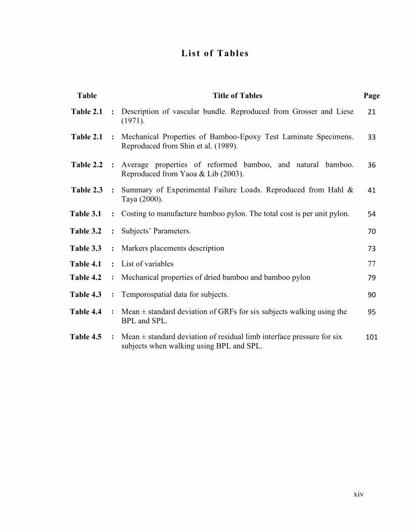
Table Title of Tables Page
Table 2.1 : Description of vascular bundle. Reproduced from Grosser and Liese(1971).
21
Table 2.1 : Mechanical Properties of Bamboo-Epoxy Test Laminate Specimens.Reproduced from Shin et al. (1989).
33
Table 2.2 : Average properties of reformed bamboo, and natural bamboo.Reproduced from Yaoa & Lib (2003).
36
Table 2.3 : Summary of Experimental Failure Loads. Reproduced from Hahl &Taya (2000).
41
Table 3.1 : Costing to manufacture bamboo pylon. The total cost is per unit pylon. 54
Table 3.2 : Subjects’ Parameters. 70
Table 3.3 : Markers placements description 73
Table 4.1 : List of variables 77
Table 4.2 : Mechanical properties of dried bamboo and bamboo pylon 79
Table 4.3 : Temporospatial data for subjects. 90
Table 4.4 : Mean ± standard deviation of GRFs for six subjects walking using theBPL and SPL.
95
Table 4.5 : Mean ± standard deviation of residual limb interface pressure for sixsubjects when walking using BPL and SPL.
101

xv
List of Abbreviat ions
3D Three Dimension
kPa 1x10³ Pascal
Mpa 1x10⁶ Pascal
Gpa 1x10⁹ Pascal
ASTM American Society for Testing and Materials
A/P Anterior-Posterior
BPL Bamboo Prosthetic Leg
cm Centimeter
CCD Charge-coupled device
F/E Flexion-Extension
GRFs Ground Reaction Forces
IPOP Immediate Postoperative Prosthesis
kg Kilogram
m Meter
mm Milimeter
N Newton
PTB Patellar Tendon Bearing
POP Plaster of Paris
PVC Polyvinyl Chloride
ROM Range of motion
RB Reformed Bamboo
SAPs Shock-absorbing pylons
SACH Solid Ankle Cushion Heel
SPL Stainless Steel Leg
SD Standard deviation
UTM Universal Testing machine
VSP Vertical Shock Pylon

1
C h a p t e r 1
Introduction
Chapter 1 defines the background of transtibial amputations as well as the history of
prosthetics. The sections are followed by a summary of the study objectives.
1.1 Transtibial Amputation
Amputation of a lower limb body is defined as a surgical procedure that involves
the removal of a leg or part of a leg, usually as a result of severe traumatic injury or
diseases such as cancer and peripheral vascular disease. National Limb Loss Information
Center reported that in America, 90 percent of the amputations performed were resulted
from neuropathy (Dillingham et al., 2002). In India about 74 percent of lower limb
amputations were due to serious trauma sustained in road traffic accidents (Paudel et al.,
2005) and in war-torn countries such as Cambodia and Afghanistan, about 80 percent of
lower limb amputees are land mine survivors (Pe, 2005).
The current situation in Malaysia is that more than 65 percent of non-traumatic
lower limb amputations are performed on patients with diabetes (Hazmy et al., 2001). Foot
ulcers that occur as the result of high blood glucose levels in diabetics contribute to
peripheral vascular disease causing poor blood circulation and neuropathy or nerve death
which causes sensory loss in the feet (Tang, 2006).

2
As the foot tissue dies, infection can set in providing a strong base to various type of
bacteria which lead to critical phase of irreversible gangrene (dead tissue throughout the
limb). When there is no hope for the damaged tissues can be restored to a healthy condition
an amputation is crucial to protect the whole limb from the spreading infection. During the
procedure the surgeons will determine the level of amputation and cut off the damaged
tissues but still preserve the maximum possible amount of muscle and nerve tissue to leave
the patient with the greatest possible range of motion for effective rehabilitation post-
procedure (Sajja, 2005). Lower limb amputations can be categorized by several levels;
partial foot, ankle disarticulation, transtibial, knee-disarticulation, transfemoral and hip
disarticulation. The position of lower limb amputations is shown in Figure 1.1.
Figure 1.1: Classification of lower limb amputation. Reproduced from Abdullah & Uday (2005).

3
Transtibial amputation is an amputation performed anywhere between the ankle and
the knee joints (Smith, 2001). The transtibial amputee, who preserves the knee joint after
the surgery, has an advantage compared to transfemoral patient particularly. The knee joint
has a major function in maintaining overall body balance and provides the power to lower
body. Many transtibial amputees are reported to successfully establish total ambulatory as
the advantage retaining the knee joint (Smith, 2003).
After amputation surgery is performed, most of the patients experience pain in the
residual limb, as well as pain in phantom limb where they feel as if the amputated limb is
still in its former place (Carnesale, 2003). As the pain persistently bothered the patients,
many of them give up on therapy and abandon their prosthesis. Hence to reduce the
incidence rate of this problem, rehabilitation and physical therapy start as early as possible
after the surgery, usually within 48 hours after amputation, and better prosthetic-fitting are
introduced. Early rehabilitation develops a positive relationship between effective
functioning of the prosthesis and residual limb (Sajja, 2005).
1.2 History of Prostheses
The story of prostheses spans a long historic period, from its ancient beginnings to
its contemporary present to the exciting visions beyond what is currently possible.
Amputations in the early history were performed for legal punishment, religious sacrifice
and war injury (Padula & Friendmann, 1987). The first record of an amputation is in “Rig-
Vieda”, an Indian poem written sometime between 3500 and 1800BC. The poem tells the
story of a warrior queen who lost her leg in a battle was equipped with a prosthesis made of
iron (Sanders, 1986). In other ancient cultures, prosthesis began as simple leather cups and
crutches tied to the upper which then grew into modified peg to free the patient’s hands.

4
The Egyptians also made use of prosthetic limbs; archaeologists have found a prosthetic leg
which made from fibres in the wrapping of an Egyptian mummy. These prostheses were
conceivably made by the burial priests for a sense of “perfectness” and not for functioning
purposes (The Cultural Body, 2006). Figure 1.2 is the drawing found in France dating back
to 500 BC shows a man working in a field with a wooden stick under his knee showing
how important it was for people to have functioning legs in those times.
Figure 1.2: From the ancient pyramid to the present day, the field of prosthetics has changed due to
more sophisticated designs. Reproduced from Norton (2007).
Despite these early findings, humankind’s concern for rehabilitation is very difficult
to establish as many of these primitive civilizations had few written document, most history
being conveyed through generations verbally in poems and songs. Herodotus, a Greek
Historian, wrote in 484 BC about a Persian soldier called Hegistratus who was locked up
by his enemies. He was able to successfully escape by amputating his own foot and later
replaced it with wood filler prosthesis (Wilson, 1970). Pliny the Elder who was the Roman
scholar, wrote that a Roman General in the Second Punic War (218-210 BC) who had his
right arm amputated. He had a hand fashioned from iron to hide his missing limb and was

5
able to return to battle. Enhancement of prosthesis started during the Dark Ages, and even
then it was not limited just to hand hooks and peg legs. Most prostheses of that time were
made for battle and hiding deformities or injuries. A knight would be fitted with prosthetic
leg which is designed to connect with stirrups (Wilson, 1970). Efficient as they were for
their intended use, this particular device could not much use to any group other than the
knights. Civilian amputees for the most part would have relied upon pylons and other
rudimentary prostheses. During this era, the practice of ligature to stop amputee sites from
bleeding was a dead end when the surgeon at that period used to crush the residual limb or
dip it in boiling oil. A French army surgeon, Ambroise Paré later discovered a better way to
perform amputations in 1529. After a number of successful procedures, he designed the
first artificial leg for hip disarticulation which employed an articulated joint. His design is
shown in Figure 1.3. The renaissance era later steered and revitalized scientific
development through refinements in medicine, surgery and prosthetic science employed by
the Greeks and Romans. This greatly improved amputation surgery and the function of the
prosthesis.
Figure 1.3: Artificial leg invented by Ambroise Paré in the mid-sixteenth century.
Reproduced from The Cultural Body (2006).

6
After the world wars, many soldiers returned home with missing limbs and, with the
escalated number of amputees, the awareness of the problems these people faced while
attempting to return to the normal lifestyle increased. Functional prostheses were still
uncomfortable to wear but the user was much more independent and mobile with the use of
such devices. Prosthetics has come a long way; from immovable, heavy limbs to models
that are lighter, more functional and easier to wear. More recently, prostheses with
advanced designs which allow the patient to perform better ambulation and expend less
energy have become more common.
1.3 Components of Prosthetics
A prosthetic leg acts as an artificial replacement for any or all parts of the lower
limb. By using prosthesis, an individual with an amputated limb has an opportunity to
perform functional tasks, such as ambulation, more normally. Throughout the years, many
important developments in prosthetics have brought us the variety and complexity of
artificial limbs available. The basic design of the transtibial prosthesis has three major
components; socket, pylon, and foot-ankle assembly (Figure 1.4). The socket is the custom
made top portion of the prosthesis; it attaches to the residual limb and disperses pressure
around it. There are two types of socket; hard socket and soft socket. The hard socket is
directly in contact with the residual limb. It has less friction, is easy to clean and is more
durable. However, this socket is difficult to fit and adjust with residual limb changes. The
soft socket surrounds with liner as a cushion between the residual limb and the socket. It
provides comfortability to patients but may increase bulk and friction. Transtibial socket
types include silicone suction, energy-storing, patellar tendon bearing (PTB) and bent knee
designs. Figure 1.5 shows the conventional steps on making the prosthesis socket.

7
Figure 1.4: Main components in a transtibial prosthesis. From Left: The endoskeletal system andexoskeletal system. Reproduced from Schuch (1998).
Figure 1.5: Traditional process for fabricating prosthesis socket. From top left: Wrapping residual
limb/stump with moistened cast sock, dried negative mould, filling POP to obtain positive mould.
From bottom left: Rectifying positive mould, socket lamination, lower limb socket. Reproduced
from Francis et al., (2002).

8
Of all the transtibial sockets, the most common model fabricated by a prosthetist is
the PTB socket as it fully utilise the presence of patellar ligament as one of the principle
weight-bearing areas. In a regular PTB prosthesis, patient seated with knee flex about 30o
and residual limb/stump relaxed. The prosthetist will identify bony landmarks by palpation
and draw them for later use in modification of the model (Fleer & Wilson, 1962). The
negative cast is produced by applying Plaster of Paris (POP) bandage to the stump. Then, a
positive mould is created by filling the negative mould with water and POP and then
allowing it to harden (United Nations, 1997). This mould is rectified and smoothed by
prosthetist and padding is added to create pressure relief areas. Finally, the mould will be
laminated by polyethylene or carbon fibre to create a socket that can be used by the
amputee.
The pylon component corresponds to the anatomical shank and is used to connect
the socket to the foot. In an endoskeletal shank the shape is tubular as in a tube adapter, a
narrow vertical support, and sometimes rests inside a foam leg cosmetic cover. The
exoskeletal shank is made of hard outer shell that is hollow inside or filled with lightweight
material (Figure 1.4). The advantage of endoskeletal systems is it allows for realignment of
prosthetic components and it is lighter, but it less durable when compared to the exoskeletal
system. The third component of transtibial prosthesis is the foot. The foot provides a base
of support during patient’s ambulation, in addition to provide shock absorption and
additional push off during walking. Foot-ankle assemblies usually fall into four categories;
articulated, non-articulated, elastic keel and dynamic response (Figure 1.6). The most
widely prescribed foot around the world is the solid ankle cushion heel (SACH) foot due to
its simplicity, durability and low cost (Michael, 1999). The SACH foot is inappropriate for
active community ambulators and sports participants. Articulated assembly allows motion

9
on a similar level to the human ankle; the motion depends on whether it is a single or multi
axis foot while the dynamic response foot is designed to benefit athletic users with
additional power for running and jumping included in the design.
Figure 1.6: Different types of prosthetic feet. Clockwise: SACH foot, dynamic response foot and
multi-axial foot. Reproduced from Umbehr (2008).
1.4 Prosthetics in Malaysia
Today, transtibial and transfemoral amputees have a variety of fully functioning
options for their prosthesis. For instance, amputated athletes have an equal number of
options available in the market to fit sprinting, skiing, golf, swimming and other extreme
activities. However, these high-tech prostheses can cost several thousand dollars in western
countries and benefit to a very minimal patients in Malaysia. Having affordable prosthetic
legs is vital for every amputee as most jobs in the country require some level of physical
labour.

10
Moreover, a basic transtibial prosthesis which consists of SACH foot, aluminum
pylon, PTB socket and low-priced polyethylene liner is likely to cost RM4800 and above
(Baitulmal News, 2009). This price is considered too high for average-income transtibial
amputees and therefore most of the amputees cannot afford to buy the prosthesis. In 2008,
the government reported that the average annual income per household in Malaysia central
areas and rural areas were RM4000 and RM2200 respectively (Utusan Malaysia, 2009).
According to the Malaysian Social Welfare Department, less than 10 percent of amputees
use prosthetic devices (Syed Putra, 2007). The remaining 90 percent chose crutches and
low-priced wheelchairs to assist their daily ambulation. As a result of this problem, many
amputees fail to achieve complete rehabilitation and most likely give up their pre-
amputation life including their occupations and careers. In some instances amputees have to
resort to begging on the streets in order to survive.
The Social Welfare Department, based on their National Health and Morbidity
Survey findings, also reported that the incidence of below knee amputations in Malaysia is
estimated to be 1500 per annum (Syed Putra, 2007). Figure 1.7 shows the distribution of
disabled people in Malaysia in 2007, noting that the most common cause of amputation is
diabetes. The Minister of Health declared that in 2008 nearly 1.4 million Malaysians,
including teenagers, suffer from diabetes and this number is likely to rise if Malaysian food
consumption habits remain unchanged (Cruz & Goran, 2004).

11
Figure 1.7: Statistics of disabled people in Malaysia from 2004 to 2006. Reproduced from Syed
Putra (2007).
The first prosthetic workshop in Malaysia was set up in 1937 by a British doctor,
Dr. B. D. Molesworth in the small town of Sungai Buloh, Selangor, close to the capital
Kuala Lumpur. Unwanted prostheses donated by Britain and Australia veteran’s
administration were shipped to Malaysia or, as it was known at the time, Malaya. In 1949, a
similar workshop was set up in the Kuala Lumpur General Hospital by Mr. Mellowship
(Omar, 1998). This little workshop was then converted into the National Limb Fitting
Centre Kuala Lumpur in 1969 and had three main staffs, each comprising of one
rehabilitation physician and three prosthetic technicians (Category III). Staff in the
prosthetic centres primarily had on-the-job training and the number of staff that underwent
appropriate Category III training was very limited. The function of a prosthetic technician
(Category III), as described by International Society of Prosthetics and Orthotics (ISPO), is
to work under direct assistance of Category I and II in fabricating sockets and assembling
prosthetic components. However, Dr. Zaliha Omar stated in 1998 in her final report to the
ISPO workshop that Malaysia, and the South East Asia (SEA) region in particular, suffers
from a lack of certified prosthetists (Category I) and prosthetist technologists (Category II).

12
This problem leads to lack supervision of Category III staff and causes difficulties in final
production of prosthetic legs that have been subscribed to amputees.
Proper construction, aligning, fitting and adjusting a prosthetic limb requires a high
level of skill, thus there is high demand for people with these expertise. This in turn
contributes to an increase in the device’s final price. Furthermore, prosthetic components
are usually imported from western and industrialized countries. In an effort to help the low
income amputee victims, the Malaysian Government’s Rehabilitation Medicine Unit and
other non-government organizations, such as Social Security Organization (SOCSO) and
Lions Clubs International, are playing a vital role by subsidising artificial limbs to patients
and supporting them with physiotherapy sessions. However, only a small number of the
patients have the chance to rehabilitate as the aid from the organizations and hospital
machinery required are very limited. In some cases, the amputees wait for 3 or 4 years to
obtain a prosthetic leg. Below is an example story from a newspaper about an amputee who
went out into his local community to appeal for contributions and donations as his
application for a prosthetic leg through a subsidiary plan was rejected.
“When he was able-bodied, Veeran Vingan, 53, owned mini-markets in Bukit Pelanduk
and Seremban in Negeri Sembilan. But fate dealt him cruel blow as he suffers from
diabetes and lost his right leg. He used to receive aid from the Social Welfare
Department but, after a while, the money stopped coming. His wife S. Saroja, 44, is
still unemployed and the childless couple who live in Semenyih are finding it difficult
to make end meet. “With a prosthetic leg I will be mobile and hope to start small
business again, maybe selling snacks and titbits from home. These few months we have
been surviving by selling milk and flowers;” Veeran told the Kajang Rhanee who
visited him recently. Rhanee said that Taman Kajang Raya would help Veeran by
checking on his aid status with the Social Welfare Department” (Krishnan, 2007).

13
Because of costs and manufacturing, transtibial prosthetics are not readily available
in this nation. At RM 4800 to RM 8000 per unit, they are too expensive for the average
income person. Though research on advanced functional prosthetics continues, it illustrates
that sometimes improving the technology is not the solution. As the demand increases, it is
becoming more significant to take the cost and complexity out of the design to make more
affordable prosthetic devices for everyone. In an effort to describe appropriate lower limb
prosthetic function for the low income amputees, some articles have been made statements
suggesting they be “only for walking” (Edelstein, 1998) and restore some “function and
appearance” of the human limb (Craig, 2005) including the provision of a “base of
support”.
The previous method used for producing a low cost prosthetic by researchers
employed simple techniques, minimalistic designs and even utilized recycled items. The
hydrostatic cast system developed by Syed Shikh (2008), for example, introduced socket
fabrication methods that did not required a highly skilled prosthetist. The system applies
uniform water pressure to produce the negative mould. When uniform pressure is applied in
this way the socket takes the exact shape of the residual limb, thus creating total contact for
the socket. Mukti Limb by the Mukti Organization is another research project that used
techniques requiring less skill to generate a low-cost prosthetic leg.
A high density polyethylene (HDPE) irrigation pipe is used to make the socket and
the shank of the limb. The pipe moulds easily when it has been heated. Once a plaster
mould is made of the residual limb, a cardboard cone is glued to the bottom of the mould
and the cone is filled with POP to make a positive mould for the shank of the limb (Strait,
2006). Another well-known, low-cost prosthetic component is the Jaipur foot. The Jaipur
foot has an appearance like a real foot, is able to bend in all directions enough to allow a

14
person to squat and walk on uneven terrain and is manufactured at a very low cost (less
than $5 USD) (Werner, 1998). The foot is made from wood, sponge and rubber and is
created using a heat-moulding process in iron moulds. The outer rubber gives the foot its
realistic appearance and natural colour as well as providing waterproofing for the wooden
block inside. This is shown in Figure 1.8.
Figure 1.8: From left: Jaipur Foot, Niagara Foot. Reproduced from Strait (2006).
The Niagara foot as shown in Figure 1.8 is a simple yet practical, inexpensive and
sturdy alternative. The foot is made of a single piece of Delrin plastic formed to imitate the
biomechanic function of a normal human foot. The shape of the foot provides energy return
similar to high-end feet models offered in the United States. Although weight and energy
expenditure are not an issue, the cosmetic appeal of the foot and the ability to wear shoes
create a few problems for this design. The foot appears to be less stable as it produces an
irregular motion throughout the gait cycle (Strait, 2006).
There are numerous published articles on producing low cost artificial leg, but
according to ISPO consensus conference on appropriate technology in developing countries
in 1995 most rehabilitation research target low cost production of socket fabrication and
foot components (Heim, 2000). This study attempts a new approach to reduce transtibial
prosthetic price by creating an economical pylon from a naturally-sourced material;

15
bamboo. Bamboo is a natural fibre-reinforced composite material which possesses
favourable mechanical properties to warrant its use as a structural material. In this paper,
the bamboo pylon was evaluated in mechanical properties tests and clinical tests with
transtibial amputation patients.
1.5 Objectives of Study
The objectives of this study are:
To evaluate the mechanical strength of bamboo to asses that it is appropriate as a
prosthesis component.
To develop a bamboo pylon from natural resources with minimal manufacturing
process and cost.
To determine through gait analysis test whether a change in prosthetic pylon will
affect the prosthetic leg efficiencies.

16
C h a p t e r 2
Literature Review
Bamboo is a unique plant on earth and it is acknowledged as “the wood of the poor”
in India, “the friend of the people” in China and “the brother” in Vietnam (Farrely, 1984).
Bamboo is a composite materials, built with combination of fibres and cellulose. Bamboo
plants are utilized for many different applications since thousand years ago. A few species
are chosen for specialize uses, while other species are still abandon. The bamboo has been
seen into diversity of products ranging from household products to industrial purposes.
Among the examples of bamboo products are food containers, handicrafts, toys, furniture,
flooring material, pulp and paper, boats, charcoal, musical instruments and weapons. The
outstanding of the mechanical behavior of bamboo in various daily usages has shown its
great potential to be used as a supportive material for amputees. In many overly populated
regions of the tropics, certain bamboos supply the one suitable material that is sufficiently
cheap and plenteous to meet the need for eco-material pylon.
2.1 Taxonomy, Growth and Climate
Bamboo belongs to the member of the natural grass family Gramineae, under the
subfamily Bambusoideae, in the group of angiosperms (Chapman, 1996; 1997). Some
examples of bamboo genera are Bambusa, Arundinaria, Chimonobambusa, Holttumochloa,
Oxytenanthera and Sinarundinaria. It grows in a warm atmosphere, plentiful moisture, and
fertile soil, except for extremely sandy, saline, or drenched soils with about 1250 species.
The bamboo plants are identified throughout the globe (Austin & Ueda, 1972; McClure,
1966; Wang & Shen, 1987) and half of these species grow in Asia, typically within the

17
Indo-Burmese region, which is measured to be their area of origin (Grosser & Liese, 1971).
In the study of bamboo habitat, Lee et al., (1994) found that the smaller bamboo species are
mostly found in high elevations or temperate latitudes, and the larger ones are abundant in
the tropic and subtropic areas. Bamboo new line can be distinct by its root system as either
sympodial (clumping) or monopodial (running) (Figure 2.1). The monopodial bamboos are
invasive and spread rapidly, while the sympodial bamboos generally stay cramped to a
single area. Even though there are species that flower annually, bamboo reproduces
asexually without flowering and without seeds, but sometimes it can also reproduce with
flower throughout the year.
Figure 2.1: (A) Sympodial rhizome of Bambusa beecheyana. (B) Monopodial rhizome of
Arundinaria amabilis. Reproduced from Farelly (1984).
Malaysia, a tropical country has approximately 70 known bamboo species, 50 in
Peninsular Malaysia, 30 in Sabah and 20 in Sarawak (Wong, 1989). However, only l0 to 15
species are known to be valuable and commonly used (Abd. Latif, 1987). In this country,
bamboo distributes from sea level to 3000 meter above. All the species are grouped under

18
10 genera: Bambusa, Chusquea, Dendrocalamus, Dinochloa, Gigantochloa, Phyllostachys,
Racemobambos, Schizostachyum, Thyrsostachys and Yushania. The most common species
are Gigantochloa scortechinii, Dendrocalamus pendulus, bambusa heterostachya,
Schizostachyum grande and Schizostachyum zollingeri in the Southwest coast and Bambusa
farinacea, Gigantochloa ligulata, Bambusa blumeana, Gigantochloa levis, and
Gigantochloa latifolia in the Northern area of Malaysia (Mohamed & Appanah, 1998).
2.2 Anatomy of Bamboo
The anatomical structure of bamboo has been discovered for decades and numerous
studies have been published (Velasquez & Santos 1931; Ghosh & Negi 1959; Grosser &
Liese, 1971; Wu & Wan, 1976; Hsiung et al., 1980; Farelly, 1984; Kawase et al., 1986;
Abd Latif et al., 1990; 1993a; 1993b; Janssen, 1991; Liese, 1992; Wu et al., 1996).
Generally, the main components of a bamboo plant include rhizomes, culms/stems,
branches, and leaves as shown in Figure 2.2.
Figure 2.2: Anatomy of Bamboo. Reproduced from Farelly (1984).

19
Culms or Stems are the most noticeably element of a bamboo plant. It is comprises
of about 60 percents parenchyma, 40 percents fibres and 10 percents conducting tissue. The
culm consists of internodes and nodes. At the internodes, the cells structures are axially
oriented, while at the nodes, cells provide the transverse interconnections (Liese, 1986).
The internodal sections of the culm are hollow and the vascular bundles in the cross section
are scattered throughout the culm instead of in a cylindrical arrangement. The properties of
the culm are determined by its anatomical structure of a transverse section by the shape,
size, arrangement and number of the vascular bundles (Ghavami et al., 2003). The vascular
bundles of bamboo internodes consist of two metaxylem vessels, phloem, protoxylem
attached fibre sheaths and depending on the species, additional fibre bundles (Figure 2.3).
Figure 2.4 represents a three-dimensional (3D) structure of the vascular system at the nodal
region. The model was reconstructed from successive sections and vascular bundle figure
left in decomposed culm.
Figure 2.3: Vascular bundle with two metaxylem vessels (V), phloem (Ph) with sieve tubes
and companion cells, protoxylem, and surroundings fibre (F) sheaths in Phyllostachys edulis.
Reproduced from Liese (1998).
Ph
VV
F

20
Figure 2.4: Illustration of vascular bundles within the nodal region. Reproduced from Liese (1998).
At the peripheral zone of the culm, the vascular bundles are smaller and more
numerous (Figure 2.5). Across the culm wall, the total number of vascular bundles
decreases from bottom outside to the inside, while their density (parenchyma) increases at
the same time.
Figure 2.5: Cross section of a bamboo culm. Reproduced from Liese (1985).
Both the metaxylem vessels and the phloem tissue are surrounded by sclerenchyma
sheaths. The sheaths vary significantly in size and shape according to their position in the
culm and the bamboo species (Grosser & Liese, 1971, 1973; Wu & Wang, 1976; Jiang &
Li, 1982). Liese (1985) has come out with a simple classification (Table 2.1) of vascular

21
bundle of the bamboo to differentiate between genera and species. Monopodial rhizomes,
such as Sinanundinaria and Chimonobambusa, represent the Type I and have generally
lower fibre content than sympodial rhizomes, such as Bambusa Dendrocalamus and
Gigantochloa, especially with Type III and IV. These differences in arrangement of
vascular bundle affect (Figure 2.6) the physical and mechanical properties like density,
strength, bending behavior, splitting and shrinkage.
Table 2.1: Description of vascular bundle. Reproduced from Grosser & Liese, (1971)
Type Vascular bundles configuration
I Consisting of one central vascular strand; supporting tissue only assclerenchyma sheaths
II Consisting of one central vascular strand; supporting tissue only assclerenchyma sheaths; sheath at the intercellular space (protoxylem)strikingly larger than the other three
III Consisting-of two parts, the central vascular strand with sclerenchymasheaths and one isolated fibre bundles
IV Consisting of three parts, the central vascular strand with smallsclerenchyma sheaths and two isolated fibre bundles outside and inside ofthe central strand
Figure 2.6: Basic vascular bundle types. Reproduced from Grosser & Liese, (1971).

22
2.3 Physical and mechanical properties
Bamboo has an appealing microstructure and macrostructure with outstanding
features which contribute to its structural integrity (Amada, 1992; Amada & Lakes, 1997).
The bamboo consists of 50 to 70 percents cellulose, 20 to 30 percents hemicellulose and 20
to 30 percents lignin, depending on the species (Liese, 1992). Cellulose fibres are aligned
along the length of bamboo providing maximum tensile, flexural strength and rigidity in the
direction of growth (Lakkad & Patel, 1981). Apart of this, density of bamboo is closely
related to the relative proportion of vascular bundle and ground tissue, in which increases
from the centre to the periphery of the culm (Sekhar & Bhartari, 1960; Sharma & Mehra,
1970) and this explains the variation of strength along the culm height. The maximum
density can be gained once the culm reaches three year old (Liese, 1986; Kabir et al., 1993;
Espiloy, 1994).
Water exists in intra-cellular and extra-cellular fluid contributes the most to the
weight of the bamboo culm. Water in bamboo culm is normally referred as moisture
content which can affect the behavior of bamboo culms (Dransfield & Widjaja, 1995),
thereby it influences the usage of bamboo. Dransfield & Widjaja, (1995) had found that the
moisture content is determined by the weight of water in bamboo culm and expressed as a
percentage of the oven dry weight of bamboo culm (Equation 2.1). The moisture content of
bamboo varies vertically from the bottom to the top portions and horizontally from the
outer layer to the inner layers. Bamboo possesses very high moisture content with green
bamboo may have 100 percent moisture and can be as high as 155 percent for the
innermost layers (Sharma & Mehra, 1970).

23
MC(%)= GW-ODWODW
×100 .Where MC = Moisture Content (%)
GW = Green Weight of bambooODW = Oven-dry Weight of bamboo
Bamboo dominates excellent strength properties, especially tensile strength. It
depends on the species, the climatic conditions and also differs along the culm height
(Sekhar & Gulati, 1973). Compressive strength increases with height but for bending, it’s
the opposite trend (Sekhar & Bhartari, 1960; Liese, 1986; Espiloy, 1987; Janssen, 1987;
Sattar et al., 1990; Kabir et al., 1991; 1993). While Liese (1986) had found that, at three to
four years of growth, the bamboo strength increased and it will decrease in the year
after. Thus, aging of a bamboo culm influences physical and mechanical properties, and
consequently it’s processing and utilization. Culm maturity is a must for the optimum
utilization of bamboo in construction and other structural uses.
Moreover, bamboo has functional gradient properties in which there is a variation of
Young's modulus across the culm section (Amada et al., 1996). Bamboo also exhibits
significant anisotropy in strength: it is more than ten times stronger in tension in the
longitudinal direction than in the transverse direction (Jain et al., 1992). The difference in
anisotropy with density in the bamboo is ascribed to the greater number of vascular bundle
sheaths in the denser bamboo (Amada et al., 1996). In addition, the specific gravity
determines to a large extent for the mechanical properties of the culm. It can be concluded
that the mechanical strength is all depends on the fibre build up, fibre diameter, and cell
wall thickness.

24
A different profile of species often results from a different anatomical, as it has been
shown for some Philippine bamboos by Espiloy (1987), Indonesian bamboos by Widjaja &
Risyad (1987) and Malaysian bamboo by Abd. Latif et al. (1990). However, a lot of
research has a common finding that, in the dry condition, the strength is higher than in the
green condition.
Bamboo shows advantages in relation to other natural fibre materials for its
lightness, high bending capacity and the fact that it is the fastest growing plant on earth. In
addition bamboo is a renewable natural resource and requires simple and low cost
processing techniques (Ghavami & Hombeeck, 1981; Liese, 1986; Ghavami & Zielinski,
1988; Ghavami 1988; Ghavami & Solorzano 1995; Amada 1996; Ghavami & Rodrigues
2000).

25
The development of a low cost pylon material in prosthetic leg involves
multidisciplinary studies. One must look into the possibility of introducing a natural
resource to the system as an alternative to produce a pylon. The most important aspect to
consider when producing a new pylon for prosthetic leg is the high in compression, long
durability and lightness. In order to achieve this, a suitable bamboo culm had been selected
to replace the conventional pylon.
2.4 Lower Limb Prosthetic in Developing Countries
In developing countries, when amputees cannot access a mobile clinic, they resort
to anything they can construct at home in an effort to continue engaging in their daily lives.
The hand-held pole leg was one of the simplest lower limb assisting devices which used
either a leather strap or a platform to support residual limb during walking (Fillauer, 1999).
This device also can be transformed into “crutch leg” by cutting away the top half of a
crutch and secured the residual limb with several straps (Figure 2.7). These types of limbs
are temporarily fine when nothing else is available. However, the device can lead to long
term fitting problems as contractures can easily form in the knee. Moreover, the
contractures will appear very rapidly if the muscle in the limb is not stretch daily (Finney,
2000).

26
Figure 2.7: From left: Hand-held pole legs, and “sawed-off crutch” leg. Reproduced from Strait(2006).
Akiode et al., (2005) described the bicycle-based limb which utilize the materials
and knowledge, used to be popular in Bangladesh. The components of this leg are
adjustable for the growth of children and parts of the limb can be adjusted with the use of a
wrench. Initially the weight of this prosthesis was an issue, but a slightly increased weight
in limb can resultant in improvement stability. The leg is built from the foot up by first
removing the seat of the bike from the frame and separating the seat post from the seat by
loosening and using the bolts and washers. The seat post is the base upside down and
forms the lower shin which then attached to a prosthetic foot. A one inch thick piece of
wood is cut to resemble a foot and lined with rubber on the undersurface for traction. The
seat support frame and rear wheel supports are separated from the bike, and the rear wheel
supports are bent to form the calf support for the socket (Akiode et al., 2005). This
prosthesis is held on with a suspension strap connecting the prosthesis to a belt worn
around the waist. The shin and foot are attached to the socket holder and the length can be
adjusted at this juncture.

27
Another common lower limb prosthesis used for developing countries is the
“bamboo leg” that is a step above from pole legs as the limb is held in a more natural, in
line position with socket. The limb design is similar to the “Peg Leg” from Dark Ages in
the 15th century (Figure 2.8). Sockets from the limb prevent the formation contractures
during patient ambulation because the knee has full range of movement. The “bamboo leg”
is constructed by adding padding to the bottom of the stump and long socks are used to
hold the padding in place. The limb is then ready to be circumferentially wrapped in plaster
bandages and attached to a piece of bamboo with a thin wire (Fillauer, 1999).
Figure 2.8: From left the traditional peg leg, and adjustable bicycle limb. Reproduced from Strait,
2OO6.
The “bamboo leg” in the limb differs from prosthetic bamboo pylon since it comes
straight from bamboo plants and does not encounter any manufacturing process. Though it
will greatly work as a temporary limb, the limb has a small base of end support that
contributes to high pressure and lead to stump contractures if it has less padding. Besides,
this limb risks on cracks of its ground base (disperse of bamboo fibres) after a series of
walking and less durable compared to traditional peg leg which was made of solid wood.
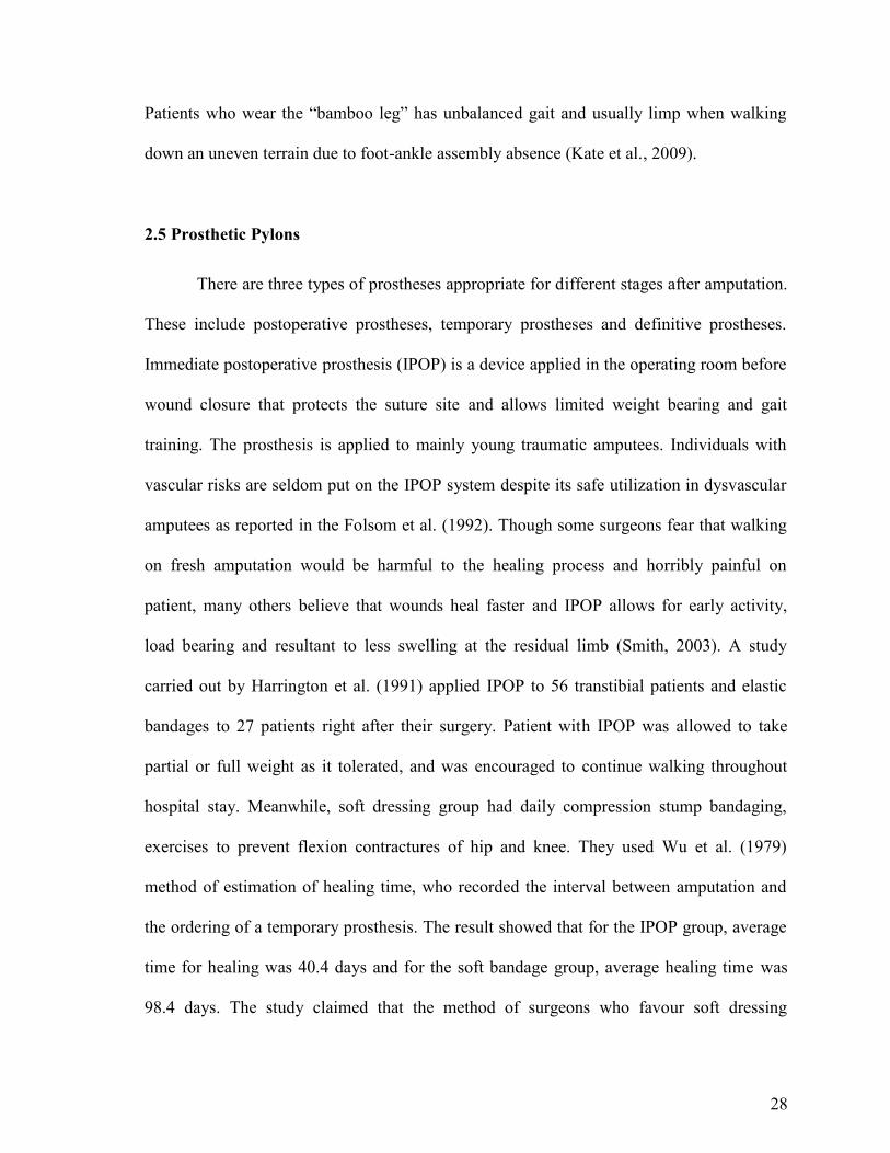
28
Patients who wear the “bamboo leg” has unbalanced gait and usually limp when walking
down an uneven terrain due to foot-ankle assembly absence (Kate et al., 2009).
2.5 Prosthetic Pylons
There are three types of prostheses appropriate for different stages after amputation.
These include postoperative prostheses, temporary prostheses and definitive prostheses.
Immediate postoperative prosthesis (IPOP) is a device applied in the operating room before
wound closure that protects the suture site and allows limited weight bearing and gait
training. The prosthesis is applied to mainly young traumatic amputees. Individuals with
vascular risks are seldom put on the IPOP system despite its safe utilization in dysvascular
amputees as reported in the Folsom et al. (1992). Though some surgeons fear that walking
on fresh amputation would be harmful to the healing process and horribly painful on
patient, many others believe that wounds heal faster and IPOP allows for early activity,
load bearing and resultant to less swelling at the residual limb (Smith, 2003). A study
carried out by Harrington et al. (1991) applied IPOP to 56 transtibial patients and elastic
bandages to 27 patients right after their surgery. Patient with IPOP was allowed to take
partial or full weight as it tolerated, and was encouraged to continue walking throughout
hospital stay. Meanwhile, soft dressing group had daily compression stump bandaging,
exercises to prevent flexion contractures of hip and knee. They used Wu et al. (1979)
method of estimation of healing time, who recorded the interval between amputation and
the ordering of a temporary prosthesis. The result showed that for the IPOP group, average
time for healing was 40.4 days and for the soft bandage group, average healing time was
98.4 days. The study claimed that the method of surgeons who favour soft dressing

29
whenever IPOP method is possible and delayed weight-bearing after amputation is
unreliable. The biggest benefit of IPOP is that patients often become less focused on the
loss limb but switches to a mind set of recovering and regaining an active life.
The temporary prostheses also known as interim prosthesis are used in the interval
between amputation and the fitting of a permanent prosthesis (Fulford & Hall, 1968).
Superior to IPOP, this prosthesis is applicable for every amputee while it still allows early
ambulation and promotes residual limb shrinkage and continued process of residual limb
maturation which can take 6 months and sometimes longer (Pandian et al., 2001).
Definitive prostheses as described in Chapter 1 may have either endoskeletal (modular) or
exoskeletal design. The endoskeletal design is more common (Harrington, 1984) which is
made of metal, titanium, steel, aluminum alloys or sometimes from carbon fibre. Pylons in
the IPOP and interim prosthesis systems are always endoskeletal and modifiable. The pylon
in IPOP and interim prosthesis usually has an adjustment mechanism so that the prosthetist
can alter the alignment as the patient’s ability to walk improves. The adjustable coupling
(Figure 2.9) consists essentially of two plate assemblies which is held together by a central
toggle pin. It is mounted to a middle plate and part of one plate assembly comes with four
screw subassemblies, spaced 90 degrees apart, which contain independently adjustable to
provide adjustment for flexion-extension and adduction-abduction. Modifications to the
adjustable pylon of these two prostheses may correct gait deviations and increase energy
efficiency while the sockets significantly reduces edema (Seymour, 2002).
Another interim prosthesis for transtibial, Scotchcast® P.V.C was introduced by
Wu et al. (1980). The Scotchcast tape is applied all over the residual limb as the stump
socket and wound protector, then pylon unit is made of thermoplastic polyvinyl chloride
(PVC). The pipe is softened on one end with a heavy-duty hot air blower such as heat gun,

30
then snugly fitted to the metal plug attached to the top of the SACH foot. The junction of
pipe over plug is further reinforced with a hose clamp. Then, the proximal end of the PVC
pipe is then sliced longitudinally into four sections, and bent outward into X-shaped bars
(Figure 2.9). An advantage of this technique, besides light weight, comfortable fitting, and
only rare need for realignment, is the reduction of fabricating time, often to less than 2
hours. Wu et al. claimed that using Scotchcast® interim pylon had resulted in improved
patient care at Veteran Affairs Medical Centre, Chicago.
Figure 2.9: From top left: IPOP prosthesis in bilateral amputation, the adjustable coupling
assembled used in IPOP and interim prosthesis, a below knee adjustable pylon used in current
practice. From bottom left: Scotchcast® interim pylon in alignment process, Endolite® Telescopic-
Torsion pylon, Sathi limb. Reproduced from Wu et al. (1979).

31
Therefore, the choice of appropriate prosthetic components as part of prosthetic
prescription is critical to user comfort. Shock-absorbing pylons (SAPs) are designed to
reduce shock forces during walking and other high impact activities. SAPs are spring like
mechanisms that are fitted in the shank section of transtibial prostheses (Figure 2.9). They
shorten telescopically with applied axial loads, thereby decreasing the stiffness of the
prosthesis and presumably reducing the impact forces associated with walking. The
kinematic responses of locomotor system during walking actively attenuate impact forces,
while passive attenuation is provided by the structure and viscoelastic properties of tissues
(Lafortune, 1994). Insufficient shock absorption during gait has been attributed to low back
pain (Voloshin & Wosk, 1982; Collins & Whittle, 1989), cartilage degeneration at the
joints (Radin et al., 1973), and osteoarthritis in the ankle, knee and spine (Collins &
Whittle, 1989; Nack & Phillips, 1990).
Mooney et al. (1995) examined the differences in the ground reaction forces (GRFs)
and moments of force during gait between the sound and residual limbs of a single
transtibial amputee using the Flex Foot Re-Flex Vertical Shock Pylon (VSP), a type of SAP
that uses a pistoning pylon assembly along with a leaf spring. The subject was tested at
with the VSP and then with the shock absorber immobilized. The investigators found that
when the VSP was disabled, the vertical GRF during prosthetic stance exhibited a third
peak in midstance and slightly decreased forces during the loading response phase and the
anterior-posterior GRFs were slightly decreased. Based on Gard & Konz (2003) study, shot
term benefits for amputees walking with SAPs may include comfort and better prosthetic
performance during gait, whereas long-term use of these devices may prevent joint and
back problems that can arise from walking on a rigid prosthesis.

32
In developing countries, the Transtibial Plastic Modular Component also called as
Sathi Limb can be used with any socket design and any foot including the bare foot models.
The use of thermoplastic components in prosthetics enables technicians to utilize the
inherent characteristics of plastics in that they are lightweight, inexpensive, non-corrosive,
and water resistant. The lighter the prosthesis, the less energy the amputee has to use to
walk. A light prosthesis also reduces shear forces on the limb and decreases the pistoning
action on the limb (Sarani, 2004). The Sathi limb is made out of lightweight, high–density
polyethylene water pipes with four ribs to give the pipe strength (Figure 2.9). The Sathi
limb is made up of a polypropylene pylon, and has 20 different sizes to suit almost all
lengths of residual limbs below the knee, a socket adapter and 2 discs, one placed below the
socket and the other above the foot piece for alignment in the anterior-posterior, medial-
lateral and able to tilt in all directions.
Several types of prosthetic pylons were described in this sub-chapter as well as the
techniques used for their manufacture. The advantages of traditional modular pylon from
Titanium or Steel Alloys are it has great accuracy in alignment, alignment can be changed
at any point of time and the other components can be reused after changing sockets to
definitive prosthesis. On the other hand, the traditional endoskeletal pylon can be
expensive, heavy and unlike the Sathi limb, it cannot be assemble to the feet without a
pyramid adaptor. The current study concerns is the same as Sathi Limb to produce a low
cost pylon with easy and quick alignment but rather than manufacture pylon from high
density polyethylene, the bamboo pylon is made from natural resources with less
manufacturing process and come along with biodegradable properties.

33
2.6 Mechanical Properties of Bamboo
Researchers in the last twenty years had focused on mechanical properties of green,
dried and reinforced bamboo. Other literatures on bamboo had discussed on methods to
enhance the strength and durability by altering the original structure of the plant. To
maximize the utilization of bamboo, its fundamental physical and mechanical properties
must be fully understood. Studies have demonstrated that the physical and mechanical
properties of bamboo mostly depend on the species, soil, silvicultural treatment, harvesting
season, felling age and moisture content (Jain et al., 1992; Sulaiman et al., 2006; Lee et al.,
1994). Shin et al. (1989) investigated tensile, compressive, flexural and inter-laminar shear
properties of bamboo-epoxy composites of varying lamina numbers. In this study, the
bamboo tested belonged to species Bambusa Paravariabilis which is laminated into three
layers, five layers and seven layers. These samples were then tested on Universal Testing
machine (UTM) with crosshead speed of 1 mm/min. The samples dimensions and results of
the tests are presented in Table 2.2.
Table 2.2: Mechanical Properties of Bamboo-Epoxy Test Laminate Specimens. Reproduced from
Shin et al. (1989).

34
Additional in lamination layers was accompanied by a decrease in tensile strength
and an increase in Poisson Ratio and Young’s modulus. This is possibly because the
decrease in longitudinal strain is greater than decrease in tensile strength. The group
investigated compressive properties by using a thin-plate compression set up which was
modified from American Society for Testing and Materials (ASTM) D3410 standards. To
ensure that fractures occurred in the middle portion of the test laminate, the two ends were
reinforced with aluminium tabs. Flexural properties of specimens were tested by three-
point bending. In Figure 2.10 the load-displacement curve showed an early linear segment,
followed by a non-linear segment beyond 50 percent of fracture load until ultimate strength
was applied. Following that, an irregular, staggered decreased in load was observed. This
can be attributed to a demonstration of strength in the respective laminae and at the end of
the study, Shin et al. (1989) could conclude that, at 61 GPa of Tensile Modulus, 27.9 GPa
Compressive Modulus and 20.2 GPa of Flexural Modulus; bamboo reinforced composites
posses specific strength superior to that of ordinary fibre-glass reinforced composites and is
3 to 4 times stronger than mild steel.
Figure 2.10: A load-displacement curve for a bamboo-epoxy laminate specimen under three-point
bending. Reproduced from Shin et al. (1989).

35
2.7 Mechanical Properties of Modified Bamboo
In order to make a pylon for a prosthetic leg, one must consider the weight, durability,
shock absorption rate, life span and also the strength of bamboo in order to get a successful
prosthetic restoration. Reformed bamboo is one kind of bamboo which uses a simple
technique that will increase the properties of a normal bamboo. It is said that this reformed
bamboo is denser than normal bamboo, and thus contains more bamboo components within
the same volume (Yaoa & Lib, 2003). There are several ranges of reformed bamboo which
currently being produced: the plain reformed bamboo, the reformed bamboo/aluminum
composite, and the reformed bamboo/glass fabric/aluminum composite.
Various types of reformed bamboo resultants to different mechanical properties of
bamboo (Chung & Yu, 2002, Amada et al. 1997, Gibson et al., 1995, Ray et al. 2004, Silva
et al., 2006, Li, 2004, Ghavami et al., 2003) and many of researchers tends to replace
tubular steel to bamboo for construction purposes due to its superior properties like high
strength to weight ratio, high tensile strength and other factors like low cost, easy
availability and harmless to the environment during service. The average properties of
reformed bamboo and natural bamboo were listed in Table 2.3. It was found from the table
that all the properties of reformed bamboo are obviously better than that of natural one
(Yaoa & Lib, 2003).

36
Table 2.3: Average properties of reformed bamboo, and natural bamboo. Reproduced from
Yaoa & Lib (2003).
.
This study will use only one type of modified bamboo which is plain reformed
bamboo as prosthetic pylon because in the end, the researcher wants to produce a reliable,
strong, durable and economical using natural ecomaterial that can be disposes with
minimum impact on the environment.
2.8 Mechanical Properties of Prosthetic Pylon
Within the field of prosthetics in the world today, there is a great variation in
fabrication techniques and choices of pylon-to-socket attachment systems. The prosthetist
chooses a combination materials and components that will provide sufficient strength and
function. When presented with fabrication and componentry options, the practitioner
prefers to be guided by empirical, objective data. Because of the lack of data, the prosthetic
device is often overbuilt. The result may be the extra weight of unnecessary materials or a
pylon attachment system that one assumes is safer but may be only heavier. Very few

37
published research has been conducted on the stiffness and mechanical properties of pylon-
to-socket attachment systems.
Current et al, 1999 is one of the first published articles which introduced the testing
method on a whole set of prosthetic leg. Loading parameters and methods were developed
practically to imitate the International Standards Organisation (ISO) standards since
structural testing of lower limb prostheses have not yet been established. However, this
design method makes the results are relatively doubtful. The purpose of the investigation
was to quantify the structural strength of various transtibial composite sockets. The
experimental setup simulated the instant of maximum loading during the late stance phase
of gait. A standard four holes distal attachment plate was used to connect the socket and
pylon. Each sample was loaded to failure in a servo hydraulic materials test machine at 100
N/s. Their results showed that all failures occurred at the site of the pyramid attachment
plate and none of the composites in the study met the ISO standards for level A100, loading
condition II (4025 N), as required for other prosthetic componentry.
According to Neo et al, (2000) from National University of Singapore; in order to
achieve compound loadings via the application of a single test force likewise Current et al.
(1999) study, the prosthesis tested must be aligned and set up strictly according to the
specifications as documented in ISO 10328. In Neo et al. (2000) study, a simple alignment
device and method is applied to prepare transtibial prosthetic assemblies for structural tests.
Actual socket and pylon were used in the test but the foot was replaced by an aluminum
foot block as there were concerns that the flexibility of a prosthetic foot might cause
excessive deflection altering the loading conditions on the socket.

38
The alignment apparatus consisted of the main frame, the top plate, the knee locator
and an alignment rod (Figure 2.11). With the aid of the alignment apparatus, the test
prosthesis was aligned as stipulated in ISO 10328 as follows:
a. The knee joint centre was directly above the origin of the (loading) coordinate axes
and lying on the u-axis (a line extending from the origin and passing through
effective ankle and knee joint centres)
b. The knee joint centre was at a height of 500 mm from the origin
c. The knee joint centre-line was parallel to the o-axis (a line perpendicular to u-axis
and parallel to effective knee joint centre-line)
d. The components were adjusted to a "worst alignment" configuration
Figure 2.11: A schematic of the entire test fixture setup. Reproduced from Neo et al. (2007).

39
For the transtibial prosthetic socket, the location of the knee centre-line and knee
centre is not easily identified due to the absence of a knee unit. In the study, a simple knee
locator was designed to provide a mechanical means of identifying the direction of the knee
centre-line and the position of the knee. The locator, together with the main frame and the
alignment rod enabled the various components within the prosthetic assembly to be
properly orientated and positioned.
In year 2000, Hahl and Taya from Seattle modified Saito et al. (1997) transtibial
prosthesis design by replacing the Aluminum pylon with fibre reinforced plastic material.
The new design was then tested to ensure that it satisfied the ISO 10328 standard
prostheses. At first Young’s Modulus of the new material fibre reinforced plastic was
discovered. The Young’s Modulus of fibre reinforced plastic in form of tube shell is 12.23
GPa with Poisson’s Ratio 0.03 while the Aluminum Young’s Modulus is 48 GPa with
Poisson’s Ration 0.35.
Figure 2.12 is a photograph of the prosthesis during testing. The test set up
consisted of a data acquisition system, a charge-coupled device (CCD) camera and an
Instron mechanical testing machine. A set of jigs attached to the machine. The jigs created
compound loading conditions on the prosthesis by the application of a single offset axial
force. A failure test was performed on the prosthesis to determine the load at which it will
break. The prosthesis was arranged in the jigs at a horizontal displacement of 110 mm,
which represents the toe-off condition. A compressive load was applied to the prosthesis
using position control at a constant displacement rate of 1 mm/min.

40
Figure 2.12: Photograph of the test set up for mechanical testing of the prosthesis. Satisfies the ISO
10328 Standard. Reproduced from Hahl & Taya (2000).
Figure 2.13 is a graph for a load versus displacement as the prosthesis was loaded.
A distinct system of cracks was seen in the base of the stiffener section at a load of 6,600 N
(point A on Figure 2.13). The onset of the crack occurred at the midline of the thickness of
the foot (2.5 mm) at the base of the stiffener. The authors assumed that the crack was
caused by interlaminar failure at a load of 6,600 N. Table 2.4 is a summary of the failure
loads for the original prosthesis and the optimized design.
Figure 2.13: Load versus displacement as the prosthesis was loaded in compression. Reproduced
from Hahl & Taya (2000).

41
Table 2.4: Summary of Experimental Failure Loads. Reproduced from Hahl & Taya (2000).
In a study by Lee and Zhang (2006), a fatigue test was done on monolimb prosthetic.
Monolimb refers to a kind of transtibial prostheses with the socket and shank moulded into
one piece of thermoplastic material. Fatigue test of the monolimb was performed using a
material testing machine. As shown in Figure 2.14, the monolimb was offset by an
extension aluminum block and mounted to the actuator linked to a linear voltage
displacement transducer (LVDT) which shows the vertical displacement of the actuator.
The monolimb was loaded against a 208 rigid tilting block at the frefoot, which was
related to the heel-off phase of the gait. The tilting block was attached securely to the load
cell. The prosthetic foot was aligned such that there was no toe-in and toe-out, and the long
axes of the extension block and the tilting block were aligned with that of the prosthetic
foot. At the beginning, a 50 N test force was applied to the forefoot and the original
actuator position was recorded by the LVDT. Next, a sinusoidal waveform of pulsating
force oscillating between 800 N and 50 N at a frequency of 1 Hz was applied to the forefoot
until 500,000 cycles was reached or the test monolimb structurally failed.

42
Figure 2.14: Test set-up of the fatigue test. Reproduced from Lee and Zhang, 2006.
The result showed that the monolimb which used an elliptical foot bolt adaptor
failed the fatigue test as structural failure occurred before reaching 20,000 cycles. The
anterior aspect of the distal end of the shank created a hole on the top surface of the wooden
keel of the SACH foot. At the end, the screw broke into two separating the prosthetic foot
and the shank portion of the monolimb before completing 20,000 cycles. A better adaptor
design spreading and reducing the pressure at the junction between the shank distal end and
the top surface of the wooden keel is desired. Previous studies applied loads according to
consensus reached at the International Society for Prosthetics and Orthotics (1978) or test
methods laid out in the International Standard ISO 10328:1996 (Current et al., 1999; Neo et
al., 2000). The Compliance International Standards ensures the structural integrity on
loading. However, the authors suggested that it has been commented that the load levels set
by the standards are too severe, that many prosthetic components failed to comply with the
standards. In addition to the load level, the strict restriction on the allowable deformation
makes it difficult for plastic prostheses to comply with the standard.

43
2.9 Clinical Assessments on Transtibial Patients
Fundamentally, the goal in fitting a lower-limb amputee with prosthetic leg is to
restore the ability to perform everyday activities in an easy, natural, and comfortable
manner. Gait analysis is useful for evaluating an amputee's prosthesis by providing
objective measurements that characterize the walking pattern. As with normal walking,
amputee gait is characterised by kinetic and kinematic parameters. Comparisons are made
in terms of ground reaction forces (GRF), joint angles, moments and powers and spatial-
temporal parameters. The GRF is the propulsive force in the walking. It is equal in
magnitude and opposite in direction to the force that the body exerts on the supporting
surface through the foot. For the purpose of analysis, it is commonly broken down into
vector components. These components are orthogonal to each other along a 3D coordinate
system which knows as Fz-vertical component, Fy-antero-posterior component and Fx-
medio-lateral component. Figure 2.15 shows common vertical and antero-posterior GRF
for transtibial patients.
Figure 2.15: GRF for vertical and antero-posterior components for transtibial subjects.
Reproduced from Su et al., 2007.

44
Joint angles are important when describing the kinematics of locomotion. During
lower limb gait analysis, joint angles are observed at the pelvis, hip, knee, and ankle. The
hip reaches the adduction peak during the stance loading response, extension peak in the
terminal stance and flexion peak during the loading response. The small amount of knee
flexion observed in the loading response allows for weight absorption. Finally, the ankle
shows peak plantar flexion in terminal stance and plantar flexion at heel strike and in the
initial swing. Figure 2.16 shows common joint angles for transtibial patients.
Figure 2.16: Joint angles for hip, knee and ankle for transtibial subjects.
Reproduced from Su et al. (2007).

45
C h a p t e r 3
METHODOLOGY
Chapter 3 is divided into two sections. The first section illustrates the development of
bamboo pylon from the plant in detail. The second part of this chapter describes the
mechanical and clinical test procedures that were performed to evaluate the efficacy of the
bamboo pylon.
Figure 3.1: Flowchart of the study.
Green bamboo culms were collectedfrom farm
START
Clinical Assessment
Gait & Socket Interface PressureAnalysis
Bamboo were dried and cut
Bamboo processed:Heating & Lamination to createDried Bamboo & Bamboo pylon
Mechanical Property Tests
Experimental tests &Finite element analysis
Subjects were fitted with bamboopylon
Application of ethical clearance forclinical assessment
FINISH
Green bamboo culms were collectedfrom farm
START

46
3.1 Development of Bamboo Pylon
This subchapter explains the process to develop a piece of strong and long-lasting
plain reformed bamboo pylon from the raw material. There were 4 stages in bamboo pylon
process; harvesting, culm drying, bamboo treatment, and bamboo lamination. Each of this
process is explained in detail throughout this chapter. In this study, sympodial rhizomes
bamboo, Bambusa Heterostachya was chosen to produce a bamboo pylon as this species
can be found vastly and abundantly in Malaysia. Besides, the physical properties of the
species itself make it an excellent resource for a practical work. Furthermore, the size of the
fully grown Bambusa Heterostachya was incredibly fit for pylon manufacturing. A
flowchart of bamboo process is shown in Figure 3.2.
Figure 3.2: Flow chart of the bamboo pylon process.
Harvesting Bamboo (BambusaHeterostachya)
Node removal
Culm drying
Culm laminating
Mechanical Test
Hot Oil Soaking

47
The strength of bamboo pylon would be uncovered when the bamboo was handled
best from the moment of harvesting, transportation, storage, construction and maintenance.
Bamboo harvested at the right time of year, and abruptly out in the open to ground contact
or rain, would damage just as quickly as improperly harvested material. This would make
the physical properties of the bamboo become worst compared to others.
3.1.1 Harvesting Local bamboo
It was very important to harvest the culms when at their maturity and possessed low
moisture content, as high moisture content increased the ease and rate of pest infestation.
Harvesting of bamboo would be carrying out according to the following condition as this
ensure that the end product would last to a maximum years with no substantial defect.
Sound internodes of matured bamboo were harvested from bambusetum in Forest Research
Institute Malaysia (FRIM) between August 20th and 30th, 2006 (Figure 3.3). The samples
were placed under shades before transported to Motion Analysis Laboratory at Department
of Biomedical Engineering, University of Malaya for the next process.
Figure 3.3: The officers from FRIM were helping locating the matured bamboo.

48
Maturity of culm was a requirement for the optimum use of bamboo when
harvesting. In comparison to wood trees, bamboo lacks the vascular cambium layer
(Nguyen, 2006; Xiaobing, 2007), so that it has no marking of growth diameter and
consequently no year rings. Thus, to identify the maturity of the culm (3 to 4 years), the
author had employed methods suggested by Fu (2001) by judging the colour of culm and
measuring the volume of the bamboo clump from a diameter between 5 meter and 3 meter.
In this study, the age of bamboo culms was determined based on experience of FRIM’s
officer by using a combination of the two methods.
Figure 3.4: Culm colour (Bambusa Heterostachya) in different ages. A - one year old culm; B -
Two years old; C - Three years old; and D - Five years old.
3.1.2 Node Removal
Once the ideal bamboo had been chosen, it was removed from a clump by cutting
them just above a node about 20 cm above the ground as shown in Figure 3.5. This length
became a buffer zone for the younger ones to remain for further edibles of the rhizome.

49
Figure 3.5: The average volume of the bamboo clump was about 4 meter before harvesting.
To prepare the samples, bottom portion of three year old bamboo was used. The
length and diameter of each chosen culm was the same with the conventional pylon
measurements which was about 200 mm and 30mm ± 2mm (outer diameter) (Figure 3.6).
Nevertheless, the length and diameters of the prepared culms could be varied from the
above mentioned dimension in order to customize the prosthetic pylon for different need of
the patients.
The suitable culm in a bamboo pole was chosen when the inner diameter was half
compared to the outer diameter (Figure 3.7) which usually at 4th, and 5th internodes or 2/3
of the bamboo length from the ground level of Bambusa Heterostachya. If the inner
diameter became less than half, bamboo pylon could easily break. Results from
compression test by Ghavami and Hombeeck, (1982) had shown that the bamboo culm
with the inner diameter half of the outer diameter produce a strong rigid body compared to
inner diameter less than half of outer diameter.

50
Figure 3.6: The author was holding a potential bamboo with suitable length and size.
Figure 3.7: A good sample of bamboo culm (left) versus poor sample (right).
50
Figure 3.6: The author was holding a potential bamboo with suitable length and size.
Figure 3.7: A good sample of bamboo culm (left) versus poor sample (right).
50
Figure 3.6: The author was holding a potential bamboo with suitable length and size.
Figure 3.7: A good sample of bamboo culm (left) versus poor sample (right).

51
3.1.3 Culm Drying
The culms were treated soon after having been cut. A key factor was the sufficient
preservation of the culm. The well-shape samples were oven-dried to remove its water
content thus avoiding fungus growth or decomposition of the culms. The presence of large
amounts of starch made bamboo highly susceptible to attack by staining fungi and powder-
post beetles (Mathew and Nair, 1988). The drying treatment was conducted in an oven at
200o Celsius for 72 hours (Figure 3.8).
Figure 3.8: The bamboo culms were placed in an oven to remove its water content
The shrinkage in wall thickness and the diameter shrinkage were determined from
green to oven-dry condition. The wall thickness was determined at four perpendicular
positions while the diameter shrinkage was measured along two diameters perpendicular to
each other (Figure 3.9). Shrinkage was measured by using Equation 3.1.
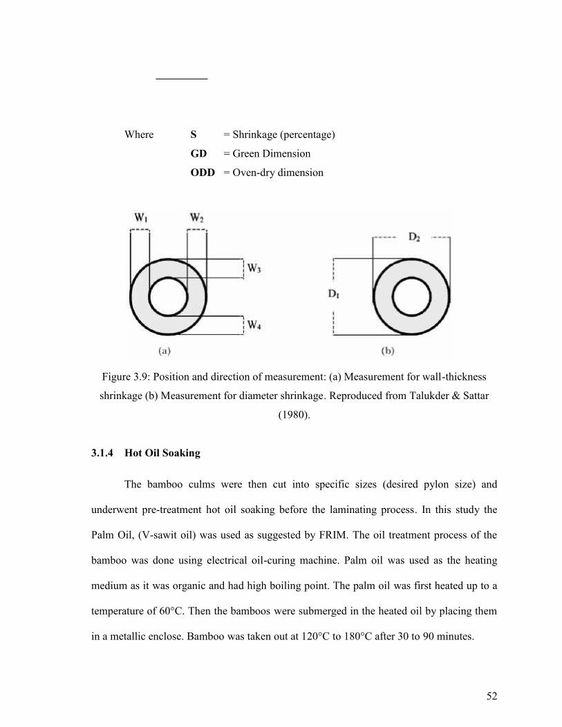
52
Where S = Shrinkage (percentage)
GD = Green Dimension
ODD = Oven-dry dimension
Figure 3.9: Position and direction of measurement: (a) Measurement for wall-thickness
shrinkage (b) Measurement for diameter shrinkage. Reproduced from Talukder & Sattar
(1980).
3.1.4 Hot Oil Soaking
The bamboo culms were then cut into specific sizes (desired pylon size) and
underwent pre-treatment hot oil soaking before the laminating process. In this study the
Palm Oil, (V-sawit oil) was used as suggested by FRIM. The oil treatment process of the
bamboo was done using electrical oil-curing machine. Palm oil was used as the heating
medium as it was organic and had high boiling point. The palm oil was first heated up to a
temperature of 60°C. Then the bamboos were submerged in the heated oil by placing them
in a metallic enclose. Bamboo was taken out at 120°C to 180°C after 30 to 90 minutes.

53
The heat treatment did not improve the mechanical strength of the bamboo as the oil
penetrates between the cells and reduce the adhesion between them. However, the oil
treatment method greatly improved the durability of the bamboo and this method was
recognized and widely used. If the bamboo was not treated by oil, the percentage of
durability would fall to 34 to 48 percents (Wahab et al., 2004).
3.1.5 Culm Laminating
To develop bamboo pylon, it was important to consider the technological properties
of the culm and its low durability against organisms. In a suitable environment, the culms
were easily attacked by fungi and beetles. Following the size preparation and drying step, at
least one layer of coating was applied on to the external surface of the culms. These
external coating would provide aesthetic effect to the culms and served as a protective layer
to prevent fungus or mites infestation that might possibly degrade the mechanical integrity
of the pylon later. Thus durability of the bamboo pylon derived from the process was
greatly improved. For the lamination, one layer of vinyl urethane adhesive with polyvinyl
acetate as hardener at ratio of 100:15 tangentially was applied to the outer and inner surface
of the culm.
The culms after application of the coating layer was subjected to 24 hours drying.
This step would harden the coating materials before adding another layer until it became
three and each laminated being approximately 1mm thick (Figure 3.10). After the
lamination layers dried, the culms were ready for the mechanical test.

54
Figure 3.10: The end product of bamboo pylon.
Table 3.1 shows the cost of bamboo pylon.
Table 3.1: Cost to produce bamboo pylon. The cost is for one unit pylon.
No Item Cost (RM)
1 Fresh bamboo (supply by bamboo plantation owner) 2
2 Oven dry 5
3 Polyvinyl acetate (adhesive) 1
4 Labor 2
Total 10

55
3.2 Mechanical Property Tests
3.2.1 Materials for Mechanical Tests
Fifty bamboo culms of Bambusa Heterostachya were collected for the mechanical
property analysis at the aged of 3 to 4 years. This bamboo had an average culm length of
5.49 m, culm diameter at the bottom was about 3.5 cm, while the top culm was about 2.3
cm. Average thickness of the culm wall was 0.97 cm. Within the study, ten samples of each
culm 1 to culm 5 were chosen for the experiments. Figure 3.11 shows the location of the
selected culms in the bamboo coordinate system. During the experiments, every bamboo
internodes with physical defects that caused by pests or chemical processed was excluded
from the sampling group. There were three mechanical tests designed for the study; tensile,
compression and flexural/bending tests. Dimensions as well as shapes for all the samples
were cut based on the assigned mechanical test according to American Society for Testing
and Materials (ASTM) Standards. In this study, the mechanical property tests were divided
into two categories of Bambusa Heterostachya bamboo; the dried bamboo and reformed
bamboo.
Figure 3.11: Bamboo coordinate system.
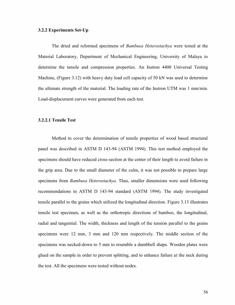
56
3.2.2 Experiments Set-Up
The dried and reformed specimens of Bambusa Heterostachya were tested at the
Material Laboratory, Department of Mechanical Engineering, University of Malaya to
determine the tensile and compression properties. An Instron 4400 Universal Testing
Machine, (Figure 3.12) with heavy duty load cell capacity of 50 kN was used to determine
the ultimate strength of the material. The loading rate of the Instron UTM was 1 mm/min.
Load-displacement curves were generated from each test.
3.2.2.1 Tensile Test
Method to cover the determination of tensile properties of wood based structural
panel was described in ASTM D 143-94 (ASTM 1994). This test method employed the
specimens should have reduced cross-section at the center of their length to avoid failure in
the grip area. Due to the small diameter of the culm, it was not possible to prepare large
specimens from Bambusa Heterostachya. Thus, smaller dimensions were used following
recommendations in ASTM D 143-94 standard (ASTM 1994). The study investigated
tensile parallel to the grains which utilized the longitudinal direction. Figure 3.13 illustrates
tensile test specimen, as well as the orthotropic directions of bamboo, the longitudinal,
radial and tangential. The width, thickness and length of the tension parallel to the grains
specimens were 12 mm, 3 mm and 120 mm respectively. The middle section of the
specimens was necked-down to 5 mm to resemble a dumbbell shape. Wooden plates were
glued on the sample in order to prevent splitting, and to enhance failure at the neck during
the test. All the specimens were tested without nodes.

57
Figure 3.12: Instron Universal Testing Machine
Figure 3.13: From left: Half-culm (A), tension test specimen (B) and specimen dimensions (C).
C
57
Figure 3.12: Instron Universal Testing Machine
Figure 3.13: From left: Half-culm (A), tension test specimen (B) and specimen dimensions (C).
C
57
Figure 3.12: Instron Universal Testing Machine
Figure 3.13: From left: Half-culm (A), tension test specimen (B) and specimen dimensions (C).
C

58
3.2.2.2 Compression Test
Compressive strength properties had been evaluated using the specimens made
parallel to the grains. The specimens were investigated using modified ASTM D 3410
standards. Shape of compression and bending test specimens was in tubular forms which
maintaining the original look of the dried and reformed bamboo. 50 specimens were tested
without bamboo nodes. As bamboo in natural tubular forms varies in diameter from bottom
to top of bamboo culm, the specimens were carefully chosen by taking the middle section
of every internode. The average length of compression specimens was 200 mm with
diameter of 30 mm. Samples in this test were clamped by metal adapters at both ends as
shown in Figure 3.14. This procedure was to ensure that fractures would occur in the
middle portion of the culm. In theory, the compression test is simply the opposite of the
tension test with respect to the direction of loading. In compression testing, the sample was
squeezed while the load and the displacement were recorded.
Figure 3.14: Specimen for compression test was clamped by metal adapters.

59
3.2.2.3 Three Point Bending Test
Standard test method to cover the determination of flexural properties of wood
based structural panels was described in ASTM D 3043 - 95 (ASTM 1994). The test
specimens were rectangular in cross-section and the length of the specimens was parallel to
grains. Specimens were prepared without bamboo nodes. Figure 3.15 illustrates how the
bending specimens were cut from the culm. The span, width and thickness of the bending
specimens were 18 mm, 4.5 mm and 1.3 mm respectively. The bending test was conducted
on an Instron 5548 Micro-Tensile Tester Machine at the Biomaterials Laboratory,
Department of Biomedical Engineering. The cross head motion was set at 3 mm/min. In
this experimental study, the specimen was supported horizontally by two steel pins and the
load was applied at the mid-point of the two supports. The resulting deflection was then
measured. The test proceeded at a constant rate of head motion until either sufficient
deflection data in the elastic range had been gathered or until specimen failure occurred.
The BlueHill 2 © Software from the Micro-Tensile Tester Machine plotted load against
center point displacement graph.
Figure 3.15: Half-culm (A), bending specimens (B), dimension of bending specimens (C).

60
3.2.3 Finite Element Analysis
Finite element analysis (FEA) is a particularly useful tool for predicting
stress behavior and can be employed before producing an optimal prosthetic design so that
it can reduce the possibility for clinical failure. In this study, FEA was performed to
investigate the maximum stress and displacement of a reformed bamboo pylon during
patient ambulation. The aim of this investigation was to assess the changes of its
mechanical behavior, specifically compression and flexural properties by using simulation
technique.
A finite element model of a reformed bamboo pylon had been constructed in Patran
© 2001 r2a software. To aid the convergence tests, simplified loading, constraints and
material properties were applied. Each of the components was modelled as a linear
geometry model and were represented by 4-noded quadrilateral elements which defined
internally by Patran © 2001 r2a software.
Figure 3.16: Finite element model of a reformed bamboo.

61
The pylon model was in tubular shape with diameter, length and wall thickness
were 30 mm, 200 mm and 10 mm respectively (Figure 3.16). Various configurations which
affected the physical properties of this material such as lamination layer and structural
composition were in consideration. A load of approximately 100 kg, of human body weight
was applied directly on the top part of the bamboo pylon with inclination of 15o to imitate
below knee walking condition. Steel adapters at both end of bamboo pylon were set to
connect the pylon to the residual limb. These adapters would be a static constraint to the
pylon. The Compressive Modulus, (Ec) and Poisson ratio (γ) applied for the FEA were
132.6 MPa and 30.7GPa respectively. These values were obtained from the previous
mechanical tests. The FEA conducted parametric analyses to investigate the stress and
displacement distributions. It also demonstrated possible fracture and distortion of the
bamboo pylon.

62
3.3 Clinical Assessment
Apart of the mechanical properties experiments, the study had carried out clinical
evaluation on the transtibial amputees. The purpose of this clinical study was to evaluate
the bamboo pylon efficiency. Differences between the bamboo pylon over the conventional
component in gait and socket interface pressure was assessed. Figure 3.17 shows the flow
chart of the clinical study.
Figure 3.17: Flowchart of the clinical study.
FLOWCHART OF THE CLINICAL STUDY
Identification of subjects &consents were taken
Ethics approval from UMMC
Subjects were casted for new PTB socketused for bamboo pylon prosthetic sets
Bamboo pylon prosthetic leg alignment
Gait and socket interface pressureanalysis after the adaptation period
Stainless steel pylonprosthetic leg
training period
Bamboo pylonprosthetic leg

63
3.3.1 Fitting Bamboo Pylon to the Subjects
Subjects involved in the study were chosen from those who were wearing similar
component of transtibial prosthesis. The components were PTB socket with liner, Stainless
Steel pylon and SACH foot. Standardisation of the components was made as to minimise
potential errors due to different component materials and designs. Each subject was given a
new socket and a SACH foot to match bamboo pylon approximately four weeks before the
clinical assessments. This was an adaptation period for the subjects to practice on the new
prosthesis set in order to obtain optimal results in gait and socket interface pressure analysis
as compared to their conventional prosthesis sets.
The new transtibial prosthetic leg was fitted to the amputee subjects at Prothetics
and Orthotics Workshop, UMMC. Due to maximum possible control over the variables
involved, one prosthetist was responsible for stump casting and subsequent cast
rectification for all patients. Manufacture of the prostheses was carried out by one skilled
senior prosthetic technician following standard procedures. The prosthetist also made sure
the patient was in healthy condition and that no pressure wounds were observed on the
residual limb. Production of PTB socket had been described in Subchapter 1.3.
Once the socket was ready, the same prosthetist would install the PTB socket with
other prosthetic components and worked on the alignment. The main principle of alignment
is to position the prosthetic socket with respect to the foot so that undesirable patterns of
force applied to the residual limb were avoided. Another purpose is to produce a normal
pattern of gait (Lannon, 2003). Basically, there were three types of alignment; bench, static
and dynamic alignment. At first, the prosthesis was bench aligned to the settings
recommended by Radcliffe and Foort (1961). Although, good bench alignment alone did

64
not guarantee the patient efficiency and comfort during gait, but it provided a good starting
point of prosthesis fitting. Proper bench alignment also meant fewer changes to the
prosthesis when initially aligned to the patient especially if the materials were made of
wood-based components (Lannon, 2004).
Once bench alignment was complete, the prosthesis must be aligned to the patient in
static standing position, therefore not moving. The goal of the static alignment procedure
was to place the socket in an optimum position in relation to the prosthetic foot at normal
stance. In the static alignment, the weight bearing must be equally distributed between the
prosthetic limb and the intact limb.
Assuming a successful static evaluation, a dynamic evaluation followed. During the
dynamic alignment, the patient walked while the prosthetist observed the impact on the gait
kinematics (Lusardi & Nielsen, 2007). The alignment of the prosthesis depended on the
prosthetist skills and experience and also the patient’s feeback. To modify the alignment,
the prosthetist adjusted the setscrews located on the lower and upper part of the bamboo
pylon adapters.
3.3.2 Systems Preparation
Clinical evaluations were done in Motion Analysis Laboratory, Department of
Biomedical Engineering, UM. Two systems involved were the gait analysis system and
socket/stump interface pressure analysis. Both were utilised to evaluate full biomechanical
changes of gait and socket interface pressure between the two different pylons, stainless
steel and bamboo.

65
3.3.2.1 Gait Analysis System
Three-dimensional biomechanics of lower limb of each participant was recorded by
using a commercial motion capture coordination known as VICON motion capture System
® integrated with two KISTLER ® force plates and Nexus 1.3 software. The VICON
System provided kinematic data for instance angular position, velocity and acceleration
while the KISTLER plates gave kinetic information like ground reaction force (GRF) and
moment. This integrated VICON system connection is shown in Figure 3.18. Motion
capture system within this study consisted of six specialized infra-red, high speed video
cameras, Model FX-20. All cameras were mounted about 2.5 meters from the ground to
provide a capture volume with length, width and height of 4 m, 4 m, and 2m respectively
(Figure 3.19). A capture volume covered an area where any point within it could be
detected by at least 2 cameras in order for the system to reconstruct a 3D model of the
point. In video acquisition, the FX-20 cameras tracked and resolved the 3D coordinates of
small reflective spheres attached to the participant’s body segments and joints to construct
human 3D model. This 3D model was determined by using Plug-In-Gait template in the
Nexus 1.3 software and used for joints range of motion calculation. Force plate is
rectangular metal platform that houses force transducers to measure the 3D forces applied
to the plate’s top surface. The force plates were rigidly embedded into the walkway and its
top surfaces were level and equal height with the floor, making it a part of the floor surface.
The plates recorded the forces exerted by the participants against the ground with a
sampling rate of 1000 Hz. Kinetic data collected from the KISTLER force plates were
integrated and synchronized with the VICON Systems ® by using MX Control and MX
Ultranet boxes. These boxes provided power, synchronization and communication between
all cameras, analog devices and the host PC. There was no time lag between both VICON

66
system and KISTLER force plates as the frame rates were set equally. The advantage of
using integrated VICON Systems ® was that it gave a clear view of real time data that were
being collected. All the analog signals from the force plates and the 3D view of the retro
reflective markers in the capture volume were readily available to the researcher in real
time (Mohd Ismail & Abu Osman, 2009).
MX Camera MX Ultranet & MX Control VICON Nexus 1.3. Software
KISTLER Forceplate Forceplate Junction Box
Figure 3.18: VICON Motion Systems architure. From left: The MX camera and Force plate were
connected to the Nexus software through MX Ultranet and MX Control.
Figure 3.19: Cameras and force plates placement in the motion analysis system.
Note: This placement and volume scale were obtained after the system calibration

67
The integrated VICON Systems ® calibration was performed prior to gait trial
began for each participant. Two types of calibration were done in the study; dynamic and
static calibration. Both calibrations used special VICON calibration wand (Figure 3.20).
Dynamic calibration worked through an algorithm to establish the scale of the experiment
volume by knowing the distance between wand markers. It involved movement of a
calibration wand which also known as ‘wand dance’ throughout the whole volume and
allowed the system to calculate the relative positions and orientations of the cameras. This
method enabled the system to reconstruct 3D position of one captured marker from 2D MX
camera images. Apart from this, static calibration was used to establish an absolute
reference of origin (0,0,0) and axes orientation (X,Y,Z). The global origin (0,0,0)
represented the center of the capture volume, and the global axes (X,Y,Z) represented the
horizontal, vertical and rotation axes of the capture volume. The KISLTER force platform
calibration was completed by the manufacture during the device installation. In this study,
the force platforms just need to be zeroed each time before a subject step.
Figure 3.20: Calibration wand placed on top of KISTLER force plates for static calibration.
Note: Force plates were embedded in floor and covered with rug.

68
3.3.2.2 Stump/socket interface pressure
F-Socket System® from Tekscan Inc. provided the pressure distribution and forces
acting on the interface between the residual limb and the prosthetic socket. The system
instantly detected displays and recorded the pressure without disturbing the normal gait of
the respective participant. F-Socket sensors, #9811 measured residual limb’ pressure
distribution using a thin disposable sheet composed of an array of pressure sensing
elements or sensels. The sensor was resistive sensor whose electrical resistance was the
result of its contact resistance of the pressure sensitive ink. In the study, two F-socket
sensors were each slotted in two PCI cuffs (Figure 3.21) which acted as a data transmitter.
The PCI cuffs were connected into 2 ports in PCI interface card of a host PC. Data from
stump/socket interface pressure was then captured and analysed by using Tekscan Research
Software v6.51. The software used a map to convert the pressure detected by the socket
sensors into the pressure data displayed in the Real-time window.
Equilibration and calibration were carried out to F-socket sensors prior to the
clinical assessments. These two methods were completed by using an air bladder. The air
bladder was consisted of an aluminum frame, and thin flexible membrane that was
pressurized against the sensor. The purpose of equilibration was to eliminate the variations
of output between sensels. As each sensel was unique and might respond slightly different,
equilibration was important for data accuracy. In equilibration, an air bladder (Figure 3.22)
applied a highly uniform pressure across the entire sensor and each individual sensel to
compensate for differences in outputs. Pressure used to equilibrate a sensor was about 100
– 200 kPa. A faulty sensor could be detected during the equilibration step; it showed in the
Real-time window map display; a different output between its sensels. After equilibrating
the sensor, the calibration procedure was carried out. The calibration was done in the same

69
technique of that equilibration but instead of using a high uniform load, the calibration
loaded the sensor with a known weight, which was the respective participant’s body mass.
This step when observed in the Real-time window would convert the raw digital output of
the sensor to actual pressure units, Pascal.
Figure 3.21: From top Left: F-socket sensors #9811 used in the study. PCI cuff held the sensor; it
was connected to computer via PCI cable. The bottom picture shows Tekscan Research Software
v6.51.
Figure 3.22: Air bladder with its components as equilibration/calibration device in the study.

70
3.3.3 Subjects
A total of five amputee patients from Department of Rehabilitation Medicine,
University of Malaya Medical Centre (UMMC) were enlisted for the clinical experiments.
The inclusion criteria of the enrolled subjects were healthy transtibial amputees, which
were able to walk independently for at least 15 metres without complication. Subjects with
neurological or orthopaedics impairments and walking with support of gait aid were
excluded from the trial. Table 3.2 will describe the demographics data of the subjects.
The clinical study of bamboo pylon was approved by the Medical Ethics
Committee, UMMC. Prior to participating in the study, the participants were given a verbal
and written explanation of the study’s protocol by the researcher. They were also explained
about the instrumentation used in the study. After the description, participants had the
option to continue in the study or drop out at any time. Those that decided to continue
signed the University of Malaya (UM) approved consent form (Appendix 2). All subjects
were scheduled for clinical evaluations at the Motion Analysis Laboratory four weeks after
they got the bamboo prosthetic leg. The four weeks interval was served as their adaptation
period and to familiarise themselves with the use of the new prosthetic leg.
Table 3.2: Subjects’ Parameters.
Subject Age(year)
Bodymass(kg)
Height(m)
Years sinceamputation
Amputatedside
Reason foramputation
Prostheticshank
length (cm)
S1 35 108 1.76 1 Right Diabetes 25.4
S2 62 55 1.49 4 Right Diabetes 19.3
S3 57 86 1.72 5 Right Diabetes 23.7
S4 45 79 1.57 4 Right Diabetes 22.1
S5 64 100 1.63 7 Right Diabetes 24.5

71
3.3.4 Clinical Assessment Protocol
Data acquisition of integrated VICON System® and F-Socket System® were done
simultaneously in the study. The goal of the clinical assessments was to evaluate the
difference on gait and socket interface pressure distribution between Bamboo prosthetic leg
and Stainless Steel prosthetic leg.
First of all, anthropometric parameters of the respective subject were taken.
Appendix 3 shows the descriptions of anthropometric parameters and how to measure
them. These measurements were entered into the VICON Nexus 1.3 software to assist in
the 3D model processing. After being introduced to all the apparatus, F-Socket sensors and
motion reflective sphere markers were placed on the participant. F-socket sensors were
firstly trimmed to allow good intact and further conformity on top of stump curved
surfaces. When trimming a sensor, the red lines within the non-conductive rows and
columns on it were carefully cut, avoiding the sensels area. If any of the sensels were cut,
they would not be usable, and would not produce any readings. Four F-socket sensors were
placed on the subject’s residual limb to gain pressure reading from all sides; anterior,
posterior, medial and lateral. Pressure from the distal part of the residual limb was not
taken. In order to prevent sensor movement, the sensor were sprayed with non-aggressive
3M Spray Mount Repositionable Adhesive before applied it on subject’s stump. The sensor
was then wrapped with a thin, flexible skin sock before putting the prosthetic leg on (Figure
3.23). The advantage of putting the sensors on subject’s stump instead of the inner of hard
socket, was that they did not have to be removed and would be re-used when the subject
changed to the other set of prosthetic leg. Sensors would only be changed if faulty was
detected at the Real-time window display.

72
With a two-PCI Cuff F-Socket System, the data from anterior-posterior part was
recorded concurrently before recording the data from medial-lateral part. The cuffs were
fastened with Velcro straps onto the subject’s thigh and cables for PCI cuffs were handled
by a research assistant when subject walked. This step was carried out to minimise
interference during gait trials. There was no need to remove the prosthetic socket when the
two sensors exchanged as they were simply removed from the cuff units and then
reattached to the sensors from medial-lateral positions.
Figure 3.23: F-socket sensor placement. It covers anterior, posterior, medial and lateral part of
subject’s residual limb and secured by skin sock.
After the subject had put on the prosthetic leg, sixteen 14 mm motion reflective
markers were placed on the subject’s lower limb body to mark bone segments (Figure
3.24). Table 3.3 describes the placements of the markers used for the study. A diagram for
full body marker placements with label is shown in Appendix 4. Markers were adhered to
the subject’s body with hypoallergenic double-sided tape. VICON system was completely
passive and required no cables to be attached to the subject.

73
Figure 3.24: Marker placements at front and back of a subject. PCI cuffs were fastened to subject
with Velcro strap. Cables of F-Socket system were handled by a research assistant during gait trial.
Table 3.3 Markers placements description
Marker label Definition Position
LASI/RASI Anterior superior iliac spine/ASIS Placed directly over the ASIS
LPSI/ RPSI Posterior superior iliac spine/PSIS Placed directly over the PSIS
LTHI/ RTHI Thigh Placed over the lower lateral 1/3
surface of the thigh
LKNEE/ RKNEE Knee Placed on the lateral epicondyle
LTIB/ RTIB Tibia Placed over the lower 1/3 of shank
LANKL/ RANKL Ankle Placed on lateral malleolus
LTOE/ RTOE Toe Placed over the 2nd metatarsal head
LHEEL/ RHEEL Heel Placed on the calcaneous bone
Note: L and R in front of all the labels indicate left and right side respectively.

74
Prior to data acquisition, subject calibration was carried out for the VICON
System® based on the VICON Skeleton Template (.vst file) from the manufacturer. In the
capture volume, subject stood in a stationary neutral pose, to enable the VICON System®
to determine the location of all sixteen markers. Nexus then automatically displayed sixteen
nodes in the 3D Perspective view pane from the detected markers. By labelling all the
nodes, the system would generate 3D skeletal frame of the respective subject (Figure 3.25).
All calculations of range of joints motions and joints’ forces were calculated based on this
vst file.
Figure 3.25: 3D skeletal frame was generated from nodes after subject calibration was done
in the Nexus software.
Once the systems and the subject were ready, the subject was acquired to walk
several times across the two embedded KISTLER force plates before the gait trials started.
This was done to familiarise the subject with the set-up, minimise discomfort and observe
any fault in the system set-up. Ten gait trials with self selected speed were captured for the
analysis and each one would produce about five to six gait cycles. The researcher would

75
obtain socket interface measurements from anterior-posterior part of residual limb at the
first five gait trials and medial-lateral on the other five trials. Subject was also ascertained
to step on both KISTLER force plates without being informed of the locations.
All data were tracked simultaneously and in Real-time windows by using two side
by side hosts PC for each system. Post experiment evaluations will produce kinetic and
kinematic data of the subject; range of joints motions, Ground Reaction Forces and socket
interface pressure distribution which were all processed and analysed through the F-Scan
6.11 and Vicon Nexus 1.3 software.
3.4 Statistical Test
T-Test and a single factor analysis of variance (ANOVA) were used to determine
statistical significance between subjects walking using bamboo and stainless steel proshetic
legs. The parameters analyzed were bamboo mechanical strengths, spatio-temporal
parameters, GRF, joint angles and socket interface pressure. Statistical difference between
prosthetic and sound leg for both pylon materials used in gait were also analysed. The
statistical analysis was performed in SPSS ® software version 12.0. Significant level was
set at 0.05.

76
C h a p t e r 4
Results and Discussions
Chapter 4 features the results of the mechanical tests and the outcome of clinical
evaluations obtain from the preceding experiments. The chapter interprets the experimental
results in order to reflect the objectives of the study, which is to evaluate the mechanical
strength of bamboo pylon whether it is appropriate as a prosthesis component and to
compare the efficiency of gait between the Bamboo prosthetic leg (BPL) and Stainless
Steel prosthetic leg (SPL).
4.1 Variables
There were six sets of data discovered from the mechanical and clinical assessments.
Table 4.1 shows the list of all variables used within the study. Three variables were chosen
as key data to support the final research outcome and categorized as follow:
Primary data : Mechanical strength properties; tensile, compressive and flexural
modulus.
Secondary data : Ground Reaction Forces (GRF) of vertical, anterior-posterior (A/P)
and medial lateral components from the gait trials.
Tertiary data : Range of motion (ROM); hip, knee and ankle flexion-extension
(F/E) from the gait trials.

77
Table 4.1: List of variables
Outcome Category Variable Units
Mechanical Strength TensileMax. tensile strengthTensile modulus
CompressionMax. compressive strengthCompressive modulus
3-Point BendingMax. bending strengthBending modulus
σ, MPaE, Gpa
σ, MpaE, Gpa
σ, MpaE, Gpa
FEA Max. StressMax. Displacement
Mpamm
Spatio-Temporal CadenceStep lengthStep widthWalking speed
Step/minmm
m/s
GRF Vertical GRFForce normalisedPercentage of stance time
A/P GRFForce normalisedPercentage of stance time
N/kg%
N/kg%
ROM Hip, knee and ankle; flexion-extension
MinimumMaximum
DegreesDegrees
Residual LimbPressure
Anterior, posterior, medial andlateral areas
MinimumMaximum
kPakPa

78
4.2 Mechanical Strength
Bambusa Heterostachya is found in all states of Peninsular Malaysia, which has
about 70 different species of bamboo. Bamboo culm is strong and has found various
applications; from basket making to house construction. The length of the internodes varies
appreciably along the tree, while the wall is up to 20 mm thick. This plant has a wide
ecological tolerance, able to withstand severe harvesting and was chosen for the study
because of its plentiful supply. Bamboo is known to possess good strength to weight ratio
and a fast growth rate. It takes only about one quarter of the time taken by trees to reach
maturity and with present rate of deforestation, bamboo may become an increasingly
important substitute for timber in the near future (Ali, 1984).
In this project, mechanical properties of dried bamboo and bamboo pylon of
Bambusa Heterostachya were investigated to demonstrate whether it was suitable as a new
low-cost pylon material. Fifty samples from each dried bamboo and bamboo pylon
category were tested under tensile, compression and 3-point bending experiments.
Generally, it was observed that the mechanical strength was lower for the cases with nodes
within the specimen length compared to the cases where there were no nodes within the
specimen length (Subrahmanyam, 1984; Lee et al., 1994). Therefore, all the specimens
within the study were prepared without the nodes. Specimens of bamboo pylon had an
average specific gravity of 0.52 and the average moisture content was 12 percent. The
average percent shrinkages of the specimens from green to bamboo pylon were 18.21%,
9.25% and 0.02% in radial, tangential and longitudinal directions, respectively. The results
of mechanical tests are presented in Table 4.2.

79
Table 4.2: Mechanical properties of dried bamboo and bamboo pylon
Mechanical Properties Units Dried Bamboo Bamboo Pylon
Tensile Yield σt ,MPa 200.5 ± 3.1 230.3 ± 6.2
Tensile Modulus Et , GPa 43.0 ± 6.2 49.5 ± 6.9
Compression Yield σc , MPa 120.0 ± 4.6 132.6 ± 3.3
Compressive Modulus Ec , GPa 26.2 ± 4.0 30.7 ± 4.7
Flexural Yield σb , MPa 192.8 ± 8.2 220.6 ± 3.5
Flexural Modulus Eb , GPa 23.1 ± 5.5 27.2 ± 4.5
No. of samples, N = 50Values are mean ± standard deviationNo significant difference for both groups (p > 0.05)
The mean strength, σt of the dried bamboo was 200.5 MPa (SD ±3.1 MPa) and
230.3 MPa (SD ±6.2MPa) for the bamboo pylon. Modulus tensile, Et for dried bamboo and
bamboo pylon were 43.0 GPa (SD ±6.2 GPa) and 49.5 GPa (SD ± 6.9 GPa) respectively.
Tensile specimens that were tested under ASTM D 143-94 showed similar stress-strain
curves between both categories (Figure 4.1 and Figure 4.2). Basically, the tensile loads
increased linearly with the increasing strain until the point of ultimate load; when bamboo
fibres underwent breakage and exhibiting brittle fracture. The stress-strain curves showed
sharp, staggered decreases beyond the rupture points. Tensile fracture of bamboo was
mainly longitudinal cracking in the same orientation of the fibres. The tensile curves
pointed that bamboo was a brittle material which had no strain-harden property. Rosler et
al. (2007) explained that the breaking strength and the ultimate strength of one brittle
material were equal. In this type of material, tensile strength was normally negligible and
the use of the material was mostly utilized on other kind of mechanical strength.

80
Figure 4.1: Stress-strain curves for ten dried bamboo samples under tensile load.
Figure 4.2: Stress-strain curves for ten bamboo pylon samples under tensile load.
0
40
80
120
160
200
240
0 1 2 3 4 5 6 7
Stre
ss,σ
(MPa
)
Strain, E (%)
Dried Bamboo Samples in Tensile Test
Sample 1
Sample 2
Sample 3
Sample 4
Sample 5
Sample 6
Sample 7
Sample 8
Sample 9
Sample 10
0
40
80
120
160
200
240
0 1 2 3 4 5 6 7
Stre
ss,σ
(MPa
)
Strain, E (%)
Bamboo Pylon Samples in Tensile Test
Sample 1
Sample 2
Sample 3
Sample 4
Sample 5
Sample 6
Sample 7
Sample 8
Sample 9
Sample 10

81
Compressive properties were investigated by using ASTM D 3410 standards. To
ensure that fractures occurred in the middle portion of the test laminate, the two ends of a
sample were clamped with pylon adapters with diameter of 30 mm (SD ±4.5 mm). The
sample was then aligned to the Universal Testing Machine with the help of a pair of
longitudinal strain gauges attached to the sides, the position adjusted until the gauges
showed identical strain to guarantee the absence of bending moment. Mean compressive
strength, σc observed in dried bamboo, being 120 MPa (SD ±4.6 MPa). Its compressive
modulus, Ec was 26.2 GPa (SD ±4.0 GPa) which was less than its tensile modulus. Figure
4.3 shows the stress-strain curves for dried bamboo samples under compression stress.
Figure 4.3: Stress-strain curves for ten dried bamboo samples under compression load.
0
20
40
60
80
100
120
140
160
0 1 2 3 4 5 6 7 8 9 10 11
Stre
ss,σ
(MPa
)
Strain, E (%)
Dried Bamboo Samples in Compression Test
Sample 1
Sample 2
Sample 3
Sample 4
Sample 5
Sample 6
Sample 7
Sample 8
Sample 9
Sample 10

82
In bamboo pylon the compressive strength, σc and modulus, Ec were 132.6 MPa (SD
±3.3 MPa) and 30.7 GPa (SD ±4.7 GPa) respectively. Even though dried bamboo and
bamboo pylon had lower compressive strength than the tensile strength, the stress-strain
curves showed that both bamboos had better physical property under compression loads
with appearance of strain-hardening region (Figure 4.4).
Figure 5.4: Stress-strain curves for ten bamboo pylon samples under compression load.
A material with strain-hardening region will not rupture at the ultimate strength due
to its plastic-deformity property (Verterra, 2007). This shows that the bamboo, when
applied under compression load would behave like steel and any other ductile materials;
which was different when it was applied under tensile load. The difference between these
was possible as bamboo is not a homogenous substance unlike the industrial materials as
Stainless Steel and Titanium. These industrial materials may possess equal strength under
compressive and tensile stress as result of their homogeneity design.
0
20
40
60
80
100
120
140
160
0 1 2 3 4 5 6 7 8 9 10 11
Stre
ss,σ
(MPa
)
Strain, E (%)
Bamboo Pylon Samples in Compression Test
Sample 1
Sample 2
Sample 3
Sample 4
Sample 5
Sample 6
Sample 7
Sample 8
Sample 9
Sample 10

83
The 3-point bending test was performed by using ASTM D 3043 – 95 standards.
The mean flexural strength, σb was 192.8 MPa (SD ±8.2 MPa) and the flexural modulus, Eb
23.1 GPa (SD ±5.5 GPa) for dried bamboo while mean flexural strength, σb was 220.6 MPa
(SD ±3.5 MPa) and the flexural modulus, Eb 27.2 GPa (SD ±4.5 GPa) for bamboo pylon.
Stress-strain curves for 3-point bending test of both categories are shown in Figure 4.5.
Bending fractures concentrated in the middle of the sample where load was applied. The
stress-strain curve in this study showed an early linear segment, followed by a non-linear
segment beyond 50% of fracture load until ultimate strength was applied. Following that,
an irregular, staggered decrease in load was observed.
Figure 4.5: Stress-strain curves for 3-point bending test of dried bamboo and bamboo pylon.
Graphs are average value of 50 samples (N=50).
0
20
40
60
80
100
120
140
160
180
200
220
240
0 2 4 6 8 10
Stre
ss,σ
(MPa
)
Strain, E (%)
Average Stress-Strain Curves for Bending Test
Dry Bamboo
Bamboo Pylon

84
The bamboo pylon in this study was treated with hot oil. The oil treatment has been
used for various wood products to improve their dimensional stability and durability
against bio-deterioration. Different types of oil treatment process has been investigated and
it was found that process conditions, such as wet or dry application and types of oils and
their temperatures were major parameter influencing overall properties of the treated
products.
Sulaiman et al. (2006) had evaluated influence of treatment process on adhesion of
laminated bamboo by using vinyl urethane adhesive. Pre-treatments of the test specimens
were conducted before mechanical test that included hot soaking. Analysis of oil absorption
was done by using Weld emission scanning electron microscope. The results showed that
as oil treatment was more severe, over 200oC for more than 120 minutes, the delamination
would increase thus reducing the mechanical properties. The reason for the lower
mechanical strength might be the presence of oil in the cell which also contributed to the
weight gained. The presence of oil could be seen as the weight of samples increased after
treatment indicating a gain in weight after heat treatment. The presence of oil could be seen
in FESEM micrographs as shown in Figure 4.6.
Treated oil penetrated in the cell wall as well as in the cell lumen. The penetration
of oil in the cell wall and lumen interfered with interfacial surface of bamboo and this
reduced the adhesion. Thus, the bamboo pylon for the trantibial prosthesis was treated at
120oC to 180oC for less than 90 minutes to avoid the circumstance.

85
Figure 4.6: Cross section of bamboo showing location of oil in between the cell wall and in the
lumen of the cell. Reproduced from Sulaiman et al., 2006.
Generally, the mechanical properties of bamboo pylon under tensile, compressive
and flexural loads were higher when compared to dried bamboo. However, there was no
significant difference (p > 0.05) when comparing the means of both groups with T-Test. No
difference was found when comparing mechanical properties between different culms’
coordinates too (p > 0.05) which was differ than Ahmad (2000). This was probably due to
different bamboo species used in the study. The author used Calcutta Bamboo which was
reported to have significant different in culm diameters between the coordinates. Bamboo,
being a biological material like timber, was subjected to greater variability and complexity,
due to various growing conditions as moisture, soil, culm coordinates, fibre bundles and the
manner of their scattering. The percentage of fibres increased from the bottom to the top of
the culm. These fibres played major role in determining the bamboo hardness (Abullah,
1983).

86
Stainless Steel and Aluminum are widely used in conventional trantibial pylon. In
annealed state, the mechanical strength of Aluminum is 48 MPa (Shasmin et al., 2008).
Other material that recently use in prosthetic pylon is fibre reinforced plastic which has
Young’s modulus at 12.23 GPa (Hahl et al., 2000). Comparing to these two conventional
substances, bamboo is expected to be a good alternative for the new pylon material in
transtibial prosthesis. With yield compressive stress and Young’s modulus of 132.6 MPa
(SD ± 3.3 MPa) and 30.7 GPa (SD ± 4.7 GPa) respectively, bamboo pylon is three times
stronger than fibre reinforced plastic and two times stronger than Aluminum. Figure 4.7
shows the Young’s modulus for various materials to compare with bamboo pylon.
Figure 4.7: Young’s modulus for conventional pylon materials, bamboo pylons and bone. Bamboo
pylon has higher Young’s Modulus than Aluminum and Fibre reinforced plastic. Reproduced from
Rho (1993)

87
4.3 Finite Element Analysis
The FEA was performed to simulate the actual condition for transtibial amputee
when walking with the BPL. Failure criteria of the BPL were made based on two criteria;
Von Mises stress test and the displacement of the model due to the applied loading
condition. The von Mises stress was used because this stress values “allow the most
complicated stress situation to be represented by a single quantity” (Shigley et al., 2004).
In essence, the von Mises stress values are a combination of all of the stress components
present in the bamboo pylon model into one value. This is a good measure of the overall
reaction of the BPL to the loading condition, because it takes all of the stress components
and outputs one stress value. This value was compared to the Yield Strength to ensure that
the material did not exceed the stress limit presented from the experimental tests.
As load of 100 kg was applied directly on the top part of the bamboo pylon with
inclination of 15o as socket to feet alignment, the maximum stress produced from the
condition was 15.6 MPa and the maximum displacement resultant from the condition was
5.66 cm. Figure 4.8 and Figure 4.9 show the diagrams from the Patran FEA software of the
Von Mises stress and displacement distribution. Since the maximum stress was lower than
the Yield compressive strength which was 132.6 MPa and the 5.66 cm was considered as a
very minimal displacement (Richardson, 2008), the bamboo was considered as safe and
would make an adequate pylon material.

88
Figure 4.8: Von Mises stress for bamboo pylon under 100 kg loads.
Figure 4.9: Maximum displacement for bamboo pylon under 100 kg loads.

89
4.4 Spatio-Temporal Parameters
Six subjects with unilateral transtibial amputation were enrolled in this study. Their
average age was 52.60 years (SD ±12.30 years). Their average height and mass were
163.00 cm and 75.40 kg, respectively. The subjects were on average 4.20 years since
amputation and walked without an assistive device. Analyses for spatio-temporal
parameters were categorized into 4 components; prosthetic and sound side from both
prosthetic legs. Data was averaged from at least three gait cycles from each subject.
Statistical test was performed by using one-way ANOVA, with significant level set at 0.05.
For the spatio-temporal parameters tabulated in Table 4.3, there was no significant
difference (p > 0.05) found between prosthetic and sound side when subjects walking with
either BPL or SPL. Values for all sound sides were slightly higher than prosthetic side
except for step length and step width for BPL which slightly higher from the sound side.
Significant difference between BPL and SPL category was found in the step width (p =
0.01). Cadence, step length and walking speed of BPL were comparable to SPL (p > 0.05).
All values from walking with SPL showed higher values compared to BPL. Figure 4.10
shows the box plots for cadence. Cadence for sound side with SPL was the highest value
among all while cadence for prosthetic side with BPL being the lowest. The cadence value
between sound side of BPL and prosthetic side of SPL was almost equal.
It has not been shown that the use of lightweight prosthesis is beneficial for
amputees. None of the previous studies (Godfrey et al., 1977; Skinner and Mote, 1989;
Hale, 1990; Czerniecki et al., 1994) evaluating the effect of prosthetic weight on gait in
amputees has shown an improvement in subject preference, walking speed or energy
expenditure with a lighter prosthesis.

90
Table 4.3: Temporospatial data for subjects.
Variables Units BPL SPL
Prosthetic Side Sound Side Prosthetic Side Sound Side
Cadence steps/min 73.59 ± 4.55 76.79 ± 4.33 76.80 ± 6.91 81.52 ± 9.05
Step Length m 0.38 ± 0.08 0.37 ± 0.16 0.40 ± 0.14 0.47 ± 0.17
Step Width m 0.25 ± 0.04 0.24 ± 0.04 0.33 ± 0.10* 0.33 ± 0.12*
Walking Speed m/s 0.45 ± 0.13 0.48 ± 0.13 0.57 ± 0.20 0.59 ± 0.18
Values are mean ± standard deviation from (N=6)*Significant difference (p < 0.05) between category (BPL and SPL)No significant difference was recorded between legs within same category (p > 0.05)
Figure 4.10: Box Plots of subjects’ cadence.
65.00
70.00
75.00
80.00
85.00
90.00
95.00
BPLProsthetic Side BPL Sound Side SPL Prosthetic Side SPL Sound Side
Step
s/m
in
Box Plots of Cadence
Q1, Q3
Min, Max
Median

91
Meikle et al. (2003) indicated that short-term intervention with increased prosthetic
mass had no significant adverse affect on gait speed. Therefore, there was no different in
spatio-temporal parameters detected when subjects wore BPL which was lighter than SPL
during the gait analysis.
4.5 Ground Reaction Forces
Although GRF were collected in the three directions, only the vertical and A/P
directions were analysed. Medial-lateral forces are important forces, but were left out in
order to focus on the forces where greater effects were identified. Figure 4.11-4.14
compares the prosthetic and sound side mean vertical and A/P GRF curves for both the
BPL and SPL used for one subject (S3), normalized by the body weight. When S3 walked
with SPL, the vertical GRF of sound side produced classic curve (Figure 4.11) as a normal
subject walked barefoot (Whittle, 1996) and the prosthetic side showed some asymmetrical
curve from the time of initial contact to the loading phase (Figure 4.12). Apart of this, when
S3 walked with BPL, the vertical GRF was asymmetrical on the sound leg while producing
flat curve between loading to terminal stance phase on the prosthetic leg. A/P GRF for S3
displayed relatively identical curves on the sound side when walking with BPL and SPL
(Figure 4.13). On the other hand, breaking force was lower on the prosthetic side when
walking with BPL than SPL. The propulsion forces on the prosthetic side were equal for
both prosthetic legs (Figure 4.14). These observations were similarly noted across all
subjects (Table 4.4).

92
Figure 4.11: Vertical GRF of sound side for one subject walking using the BPL and SPL at self-
selected speed. GRFs were normalized by body weight (BW). Shaded area represents standard
deviation.
Figure 4.12: Vertical GRF of prosthetic side for one subject walking using the BPL and SPL at
self-selected speed. GRFs were normalized by body weight (BW). Shaded area represents standard
deviation.

93
Figure 4.13: A/P GRF of sound side for one subject walking using the BPL and SPL at self-selected
speed. GRFs were normalized by body weight (BW). Shaded area represents standard deviation.
Figure 4.14: A/P GRF of prosthetic side for one subject walking using the BPL and SPL at self-
selected speed. GRFs were normalized by body weight (BW). Shaded area represents standard
deviation.

94
The highest peak on the force curve was defined as the maximal force amplitude.
Vertical GRF represented by three maximal forces (Figure 4.11). Fz1 was maximum
vertical force during the loading phase. Fz2 was vertical force during mid-stance and Fz3
was maximum vertical force in late terminal stance. In A/P GRF, two forces were identified
for analysis purposes which were Fx1 as the maximum breaking force and Fx2 as the
maximum propulsion force (Figure 4.14). The time is measured in seconds and represents
the time between the start of the stride, to the moment the force reaches the maximal
amplitude indicated by the peak. All the force data were normalized to body mass.
The magnitude of the first peak of the vertical GRF typically indicates the capability
of the locomotor system to absorb shock during gait. Previous studies of persons with
unilateral transtibial amputations reported that the first peak of the vertical GRF on the
prosthetic limb was about 5 to 15 percent higher than the sound limb (Power et al., 1994;
Snyder et al., 1995). Contrary to these finding, there was no significant difference (p >
0.05) found in the vertical GRFs between the prosthetic and sound side. The vertical GRFs
when walking with BPL or SPL was comparable (p > 0.05).
A/P GRF values would show if the alignment in prosthesis was properly done.
Significant difference for A/P GRF was found (p < 0.05) in Fx1 of SPL prosthetic side
which had greatest value among all breaking force. This showed that the ability of the
subjects to control their breaking forces when wearing the SPL. Fx1 for prosthetic and
sound side of BPL were comparable (p > 0.05) with the sound side of SPL. No significant
difference was found in Fx2 (p > 0.05) for sound and prosthetic side of BPL and SPL.

95
Table 4.4: Mean ± standard deviation of GRFs for six subjects walking using the BPL and SPL.
BPL Prosthetic Side BPL Sound Side SPL Prosthetic Side SPL Sound Side
GRF (N/kg)
Vertical Fz1 1.05 ± 0.45 1.13 ± 0.34 1.17 ± 0.31 1.02 ± 0.33
Fz2 1.01 ± 0.67 0.97 ± 0.52 0.89 ± 0.50 0.87 ± 0.45
Fz3 0.95 ± 0.34 1.06 ± 0.23 1.11 ± 0.32 1.01 ± 0.30
A/P Fx1 -0.20 ± 0.03 -0.23 ± 0.05 -0.43 ± 0.01* -0.22 ± 0.01
Fx2 0.43 ± 0.07 0.31 ± 0.04 0.47 ± 0.03 0.26 ± 0.02
Range Of Motion, Degree (o)
Hip Angle Maximum Extension 5.25 ± 0.26 0.02 ± 0.00* 4.79 ± 0.24 14.17 ± 0.71*
Maximum Flexion 37.97 ± 1.90 32.12 ± 1.65 29.27 ± 1.45 28.75 ± 1.45
Knee Angle Maximum Extension 10.00 ± 0.50 7.38 ± 0.21 8.92 ± 0.45 10.15 ± 0.51
Maximum Flexion 60.26 ± 3.05 58.41 ± 2.92 45.68 ± 2.28 39.19 ± 1.96
Ankle Angle Maximum Plantar Flexion 17.93 ± 0.89 19.80 ± 0.99 28.44 ± 1.42* 19.80 ± 0.99
Maximum DorsiFlexion 4.60 ± 0.23 3.92 ± 0.09 4.84 ± 0.24 4.02 ± 0.20
Values are mean ± standard deviation from (N=6)
*Significant difference (p < 0.05)

96
4.6 Range of Motions
Table 4.4 shows average results for hip, knee and ankle joint kinematics for all
subjects. Significant differences were found (p < 0.05) in the maximum hip extension for
both sound sides when subjects wore either BPL or SPL. Magnitudes for sound side of SPL
were highest compared to other groups (Figure 4.15). Clearly, subjects felt better stability
during gait when their body weights were supported by the sound leg.
Figure 4.15: Hip joint angular position for all subjects (N=6). Positive values indicate flexion and
negative values indicate extension.
Walking with BPL did not show any significant difference (p > 0.05) with SPL in
the knee flexion and extension of both limbs. The subjects in this study walked with 15
percent less knee flexion and 10 percent more extension than the normal individual (Su et
al., 2007). The subjects might reduce the knee flexion to minimise relative motion between
the residual limb and the prosthetic socket. Figure 4.16 shows knee joint angular position
for both limbs when wearing BPL and SPL. Ankle joint angular values were comparable (p
-20
-10
0
10
20
30
40
50
0 20 40 60 80 100
Ang
le
Percentage of Gait Cycle
Hip Angle
BPL Prosthetic Side BPL Sound SideSPL Prosthetic Side SPL Sound Side

97
> 0.05) between BPL and SPL for the maximum dorsi flexion values. Significant difference
(p < 0.05) was only found in prosthetic side of SPL for maximum plantar flexion. In
addition, the prosthetic side of SPL produced the highest magnitudes for both dorsi flexion
and plantar flexion among all limbs (Figure 4.17).
Figure 4.16: Knee joint angular position for all subjects (N=6). Positive values indicate flexion and
negative values indicate extension.
Figure 4.17: Ankle joint angular position for all subjects (N=6). Positive values indicate
dorsiflexion and negative values indicate plantarflexion.
-10
0
10
20
30
40
50
60
0 20 40 60 80 100
Ang
le
Percentage of Gait Cycle
Knee Angle
BPL Prosthetic Side BPL Sound SideSPL Prosthetic Side SPL Sound Side
-35
-30
-25
-20
-15
-10
-5
0
5
10
0 20 40 60 80 100
Ang
le
Percentage of Gait Cycle
Ankle Angle
BPL Prosthetic Side BPL Sound Side
SPL Prosthetic Side SPL Sound Side

98
4.7 Socket Interface Pressure Analysis
The residual limb interface pressure was the supporting data of this study to confirm
that there was no high stress pressure or pain occurred on subjects’ residual limbs. Socket
interface pressure analyses were made based on anterior, posterior, medial and lateral
sensor groups. The length of the sensor was divided into three boxes; the top, medial and
distal regions of the respective areas. Figure 4.18 shows colour codes used to indicate
the pressure values. The upper and lower values however did not act as a threshold that
limited the displayed pressure.
Figure 4.19 and Figure 4.20 shows the maximum pressure produced in S1’s stance
phase when wearing BPL and SPL. Maximum pressure for each box is displayed at the top
right corner of the respective boxes. Based on the diagrams and Table 4.5, SPL had higher
values in residual limb interface pressures for most of the areas when compared to BPL.
The reason for this was that the socket for BPL was newly made for every subjects based
on their present residual limb shapes and skin-bone profiles. Subjects possibly felt more
convenient and less pain when wearing the new socket from BPL.
Figure 4.18: Colour bar for stance pressures.

99
Figure 4.19: Maximum stance pressures for BPL and SPL at anterior and posterior residual limb’s area.

100
Figure 4.20: Maximum stance pressures for BPL and SPL at medial and lateral residual limb’s area.

101
Table 4.5: Mean ± standard deviation of residual limb interface pressure for six subjects when
walking using BPL and SPL.
BPL SPLMaximum pressure, kPa
Anterior 61.34 ± 32.23 62.31 ± 44.26
Posterior 31.14 ± 17.81 60.64 ± 14.53*
Medial 55.16 ± 26.55 63.75 ± 31.89
Lateral 51.96 ± 15.32 59.06 ± 15.43
Values are mean ± standard deviation
*Significant difference (p < 0.05)
In the above diagrams and Figure 4.21, pressure interface were high on anterior
and medial area especially for SPL which were 104 kPa and 140 kPa respectively. These
areas mark the patellar tendon and tibial tuberosity which had high pressure tolerant. Zhang
and Lee (2006) reported that the pain threshold for patellar tendon was 1.00 MPa while
pain threshold for tibial tuberosity was 0.89 MPa. Lowest pain threshold recorded in their
study was 0.45 MPa for distal end of fibula.
Figure 4.21: Average peak distribution at the anterior area of residual limbs for 6 subjects when
walking using BPL and SPL for 2 consecutive steps.
0
20
40
60
80
100
120
140
160
Peak
Pre
ssur
e, k
Pa
Pressure Distribution (Anterior)
SPL
BPL

102
C h a p t e r 5
Conclusions and Recommendations
Bamboo pylon was tested under three mechanical tests and evaluated under finite
element model. The results showed that bamboo was three times stronger than fibre
reinforced plastic and two times stronger than Aluminum. Fibre reinforced plastic and
Aluminum are widely used as the transtibial pylon material.
Despite the strength, bamboo had physical limitation on water resistance and
durability. These limitations were overcome through lamination process and oil treatment
that enhancing its anatomical structures. The total cost to develop bamboo pylon was
RM10 with minimal manufacturing processes involved. Apart of this, evaluation on
bamboo pylon durability was not made in this study. This evaluation could be done through
dynamic test under Universal Testing Machine for further study.
Clinical assessment was carried out to determine the efficiency of bamboo
transtibial pylon in amputees’ gait. There was no significant difference found in vertical
and A/P GRF (p > 0.05) in BPL compared to SPL. Joint kinematics for BPL was also
comparable to joint kinematics for SPL (p > 0.05) except for the hip extension (p < 0.05).
In spatio-temporal parameters, cadence, step length and walking speed of BPL were
comparable to SPL (p > 0.05).

103
References
Abang Ali, A.A. (1984). Development of basic mechanical tests for Malaysian bamboos.Pertanika 7(2), 13-17.
Abd. Latif, M. (1987). Guideline on the production of bamboo products. FRI, TechnicalInformation, No.2.
Abd.Latif, M., & Mohd. Tamizi, M.. (1993b). Variation in anatomical properties of threeMalaysian bamboos from natural stands. Journal Tropical Forest Science, 5(1), 90-96.
Abd.Latif, M., Ashaari A., Jamaludin K., & Mohd. Zin J.. (1993a). Effects of anatomicalcharacteristics on the physical and mechanical properties of Bambusa bluemeana. JournalTropical Forest Science, 6(2), 159-170.
Abd.Latif, M., Wan Tarmeze, W.A., & Fauzidah, A. (1990). Anatomical features andmechanical properties of three Malaysian bamboos. Journal Tropical Forest Science, 2(3), 227-234.
Abullah A.A.A. (1983). Utilization of bamboo s a low cost structural material. Proc. Of thesymposium on appropriate building materials for low cost housing, Nairobi, Kenya, 7-14 nov.
Abdullah, M., & Uday, P. (2005). Amputation. A publication of the National Cancer Centre ofSingapore. Retrieved 28 September 2009 fromhttp://www.nccs.com.sg/pbcation/CU/vol3_05/p7.htm.
Ahmad, M. (2000). Analysis of Calcutta Bamboo for structural composite materials, doctor ofphilosophy dissertation submitted to the faculty of Virginia Polytechnic Institute Ans StateUniversity.
Akiode, O., Shonubi, A.M., Musa, A., & Sule, G. (2005). Major limb amputations: an audit ofindications in a suburban surgical practice. J Natl Med Assoc. 97(1),74-78.
Amada, S. & Lakes, R.S., (1997). Viscoelastic properties of bamboo, Journal of MaterialsScience, 32, 2693-2697.
Amada, S., (1995). Hierarchical functionally gradient structures of bamboo, barley, and corn,MRS Bulletin, 20, 35-36.
Amada, S., (1996). The mechanical structures of bamboos in viewpoint of functionally gradientand composite materials, Journal of Composites Materials, 30(7), 800-819.
Amada, S., Ichikawa, Y., Munekata, T., Nagase, Y., Shimizu, H. (1997). Fiber texture andmechanical graded structure of bamboo. Compos. Part B, 28B,13-20.
American Society for Testing Materials (ASTM). (1994). Standard Test Methods for TestingStructural Panels in Flexure, Annual Book of ASTM Standards, ASTM D 3043 – 95, Vol.04.10, Philadelphia, PA.
American Society of Testing Materials (ASTM). (1994). Standard methods of testing smallclear specimens of timber. Annual Book of ASTM Standards. ASTM D 143-94 (Reapproved1997), Vol. 04.10, Philadelphia, PA.

104
American Society of Testing Materials (ASTM). (1994). Standard Test Methods for TestingComposite Materials in Compression. Annual Book of ASTM Standards. ASTM D3410, Vol.04.10, Philadelphia, PA.
Austin, R., & Ueda K., (1972). Bamboo, Weather Hill Publishing, New York.
Baitulmal news, (2009). Pengidap diabetes terima kaki palsu, pusat pungutun zakat. Retrieved18 May 2010 from http://www.maiwp.gov.my/index.php/berita-maiwp-informasi-28/312-hasiah-gembira-terima-kaki-palsu-setelah-21-tahun-menanti.html
Carnesale, P.G., (2003). Amputations of the lower extremity. In: S.T. Canale, Editor, Cambell’soperative orthopaedics (10th ed), Mosby, Philadelphia, PA, 575–586.
Chapman, G.P. (1996). The biology of grasses. Department of Biochemistry and BiologicalSciences, Wye College, University of London, U.K. CAB International. 14-19.
Chapman, G.P. (1997). The bamboos. Papers presented at an international symposiumorganized by the Linnean Society of London. The Royal Botanic Gardens Kew and WyeCollege, University of London, London. Linnean Society Symposium Series No. 19. AcademicPress.
Chung, K. F., & Yu, W. K. (2002). Mechanical properties of structural bamboo for bambooscaffoldings. Eng. Struct, 24,429-442.
Collins, J.J., & Whittle, M.W. (1989). Impulsive forces during walking and their clinicalimplications. Clin Biomech, 4(3), 179–187 .
Craig, J. (2005). Prosthetic Feet for Low Income Countries. Journal of Prosthetics andOrthotic,.17, 47-49.
Cruz, M.L., & Goran, M.I. (2004). The metabolic syndrome in children and adolescents. CurrDiabetes Rep. 4, 53-62.
Current, T.A., Kogler, G.F., & Barth, D.G. (1999). Static structural testing of trans-tibialcomposite sockets. Prosthet Orthot Int. 23(2),113-122.
Czerniecki, J.M., Gitter, A., & Weaver, K. (1994). Effect of alterations in prosthetic shank masson the metabolic costs of ambulation in above-knee amputees. Am J Phys Med Rehabil, 73,348-352.
Dillingham, T.R., Pezzin, L.E., MacKenzie, E.J., (2002). Limb amputation and limb deficiency:Epidemiology and recent trends in the United States. South Med J, 95(8), 875-883.
Dransfield, S., & Widjaja, E.A., (eds), (1995). Plant Resources of South-East Asia, No 7.Bamboos. Backhuys Publishers, Leiden. 15-49.
Edelstein, J. (1998). Prosthetic feet-state of the art. Phys Ther, 68, 1874–1876.
Espiloy, Z.B. (1987). Physico-mechanical properties and anatomical relationships of somePhilippine bamboos. In: Recent Research on Bamboo, Ed. Rao, A.N., Dhanarajan, G., Sastry,C.B., Proc. Interno Workshop Hangzhou, P.R. China, 1985, Singapore 1987, 257-264

105
Espiloy, Z.B. (1994). Effect of age on the physico-mechanical properties of some Phil-ippinebamboo. In Bamboo in Asia and the Pacific. Proceedings of the 4th International BambooWorkshop, Chiangmai, Thailand, 27-30 November 1991. International Develop-ment ResearchCentre, Ottawa, Canada; Forestry Research Support Programme for Asia and the Pacific,Bangkok, Thailand. 180-182.
Farrely, D. (1984). The Book of Bamboo: A Comprehensive Guide to This Remarkable Plant,Its Uses, and Its History. Sierra Club Books
Fillauer, C.E., Pritham, C.H., & Fillauer, K.D., (1989). Evaluation and development of thesilicone suction socket (3S) for below-knee prostheses. J Prosthet Orthot Int, 1, 92-103
Finney, L., (2000). Proceedings of the 10th Int Conf Biomed Eng. Singapore, 71
Fleer, B. & Wilson A.B., (1962). Construction of the patellar tendon bearing below kneeprosthesis, Artificial Limbs, 25-73
Folsom, D., King, T., & Rubin, J.R. (1992). Lower-extremity amputation with immediate post-operative prosthetic placement. Am J Surg, 164, 320–322
Francis, E.H., Tay, M.A., & Manna, L.X.(2002) "A CASD/CASM method for prosthetic socketfabrication using the FDM technology", Rapid Prototyping Journal, 8(4), 258 – 262.
Fu, J., (2001). The Competitive Strength of Moso Bamboo in the Natural Mixed EvergreenBroad-Leaved Forests of the Fujian Province, China. Doctoral Dissertation, Faculty of ForestryScience and Forest Ecology. Georg-August-Universität Göttingen, Germany.
Fulford, G. E., & Hall, M. J. (1968). Amputation and Prostheses: A Survey in North-WestEurope and North America. John Wright & Sons Ltd., Bristol, England.
Gard, S.A., & Konz, R.J. (2003). The Effect of a Shock-absorbing pylon on the gait of personswith unilateral transtibial amputation. Journal of Rehabilitation Research and Development.40(2), 109-124.
Ghavami, K. (2005). Bamboo as reinforcement in structural concrete elements. Cem. Concr.Compos, 27,637-649.
Ghavami, K. & Hombeeck, R.V., (1981). Application of bamboo as a construction material:Part I. Mechanical properties and water-repellent treatment of bamboo, Part II. Bambooreinforced concrete beams; Proc. of Latin American Symposium on Rational Organization ofBuilding Applied to Low- Cost Housing, IPT/CIB, São Paulo, Brazil, 49-66.
Ghavami, K. & Solorzano, I.G., (1995). Comparison between microstructure of bamboo culmand wood, Acta Microscopia, 3rd Inter-American Conference on Electron Microscopy and XVMeeting of the Brazilian Society for Electron Microscopy, Caxambu, M.G., Brazil.
Ghavami, K. & Zielinski, Z.A. (1988). Permanent shutter bamboo reinforced concrete slab;BRCS1, Civil Eng. Dept., Concordia University, Montreal, Canada.
Ghavami, K., (1988). Application of bamboo as a low-cost construction material, Proceedingsof International Bamboo Workshop, Cochin, India, 270-279.
Ghavami, K., Rodrigues C.S & Paciornik S. (2003) Bamboo: Functionally Graded. Asian

106
Journal of Civil Engineering (Building and Housing), 4(1), 1-10.
Ghosh, S.S. & Negi, B.S. (1959). Anatomical features of bamboo used for paper manufacture.Cell. Res. Symp. Council of Scientific and Industrial Research, New Delhi, India.139-148.
Gibson, L.J., Ashby, M.F., Karam, G.N., Wegst,U, & Shercliff, H.R. (1995). The mechanicalproperties of natural materials. II. Microstructures for mechanical efficiency. Proc. R. Soc.Lond. A., 450,141-162.
Godfrey, C.M., Brett, R., & Jousse, A.T. (1977). Foot mass effect on gait in the prosthetic limb.Arch Phys Med Rehabil, 58,268-269.
Grosser, D. & Liese. W. (1973). Present status and problems of bamboo classification. J.Arnold Arboret. 54, 293-308.
Grosser, D., & Liese, W. (1971). On the anatomy of Asian bamboos, with special reference totheir vascular bundles. Wood Sci. Technol. 5, 290-312Hahl, J., & Taya, M. (2000). Experimental and numerical predictions of the ultimate strengthof a low-cost composite transtibial prosthesis. Journal of Rehabilitation Research andDevelopment, 37(4), 405–413.Hale, S.A. (1990). Analysis of the swing phase dynamics and muscular effort of the above-kneeamputee for varying prosthetic shank loads. Prosthet Orthot Int, 14,125-135.
Harrington, I.J., Eases, S.I., & White, R.C. (1984). Use ofa pylon for early ambulation afterbelow-knee amputation : a preliminary report. Can J Surg, 27 ,500-502.
Harrington, I.J., Lexier,R., Woods, J.M., McPolin, M.F.J., & James, G.F. (1991). A plasterpylon technique for below knee amputation, J Bone Joint Surgery, 73-B, 76-78
Hazmy, W., Mahamud, M., Ashikin, N., Jamilah, S., Yee, L.E., Shong, H.K., (2001). Majorlimb amputations in Seremban Hospital: a review of 204 cases from 1997-1999. Med JMalaysia. 56 Suppl C:3-7
Heim, S. (2000). Prosthetic foot design. Paper presented at the ISPO Consensus Conference onAppropriate Orthopaedic Technology for Low-Income Countries, Moshi, Tanzania, September18–22.
Hsiung, W.Y., Quiao, S.Y., & Li, Y.F. (1980). The anatomical structure of culms ofPhyllostachys pubescens Mazel ex H. de Lehaie. Acta Botanica Sinica, 22(4), 343-348.
Jain, S., Kumar, R., & Jindal, U.C., (1992). Mechanical behaviour of bamboo and bamboocomposite, J. Materials Science, 27, 4598-4604.
Janssen, J.J.A. (1987). Recent Research on Bamboo. Proceedings of the InternationalBamboo Workshop, Hangzhou, China, 6-14 October 1985. Chinese Academy of Forestry,Beijing, China; International Development Research Centre, Ottawa, Canada. 250-256.
Janssen, J.J.A. (1991). Mechanical properties of bamboo. Kluwer Academic Publishers.Forestry Sciences, Vol.37.
Jiang, X. & Li Q. (1982). Preliminary study on vascular bundles of bamboo native to Sichuan,Journal of Bamboo Research, 1, 17-21
107
Joachim, R. Harald, H., Martin, B. (2007). Mechanical behaviour of engineering materials:metals, ceramics, polymers, and composites. Springer. ISBN 978-3642092527.
Kabir, M.F., Bhattacharjee, D.K., & Sattar, M.A. (1993). Effect of age and height onstrength properties of Dendrocalamus longispaths. Bamboo Information Centre India Bulletin,3(l), 11-15
Kate, J. J., Jennekens, F. G. I. & Vos-Niël, J. M. E. (2009) . Rembrandt’s 'Beggar with awooden leg’ and other comparable prints. Journal of Bone and Joint Surgery - British Volume,91-B(2), 278-282
Kawase, K., Sato, K., Imagawa, H. & Ujie, M. (1986). Studies on utilization of Sasa bamboosas forest resources - pulping of young culms and histological change of cell structure of theculms in growing process. Research Bulletin of the College of Forestry, Hokkaido University,Japan. 43(1), 73-98
Kiam T.S., Sulaiman, R., Manggil, P., & Hwai, Y.Y., (2005). Global Forest ResourcesAssessment Update (GBRA), Malaysia: Country Report On Bamboo Resources, KualaLumpur, 9 May, Working Paper 124.
Krishnan, G. (2007). Two families in need of help. Retrieved 15 September 2008 fromhttp://thestar.com.my/metro/story.asp?file=/2007/9/5/central/18579364&sec=central.
Lafortune, M.A., Lake, M.J., & Wilson, R. (1994). Shock transmissibility of the human body.Proceedings of the Eighth Biennial Conference of the Canadian Society for Biomechanics, Aug18–20, Calgary, AB, Canada, 168–169.
Lakkad, S. C. & J. M. Patel (1981). "Mechanical properties of bamboo, a natural composite."Fibre Science and Technology 14(4): 319-322.
Lannon, N. (2003). Trans-tibial alignment, normal bench alignment. OrthoLetter. Retrieved 20February 2009 from http://home.ica.net/~cocinc/Alignment.html.
Lannon, N. (2004). Trans-tibial alignment, static alignment. OrthoLetter, A Newsletter OnOrthopaedic Technology In Low Income Countries, 13, 11-14.
Lee, A.W.C., Xuesong, B., & Perry, N.P. (1994). Selected physical and mechanical propertiesof giant timber bamboo grown in South Carolina. Forest Prod.J. 44(9), 40-46Lee Andy, W.C., Xuesong, B., Peralt, Perry, N. (1994). Selected physical and mechanicalproperties of giant timber bamboo grown in South Carolina. Forest Products Journal. 44(9) 40-47.Lee, W.C.C., & Zhang, M. (2006). Fatigue Test of Low-Cost Flexible-Shank Monolimb Trans-Tibial Prosthesis. Prosthet Orthot Int. 30(3), 305-315.
Li, X. B. (2004). Physical, Chemical, and Mechanical Properties of Bamboo and Its UtilizationPotential for Fiberboard Manufacturing. PhD thesis, Louisiana State University.
Liese W. (1985). Anatomy and properties of bamboo. In : A.N Rao, G. Dhanarajan and C.BSastry (Eds.). Recent Research on Bamboo. Proceedings. International Bamboo Workshop,China, Hangzhou, China. Chinese Acad. For. Beijing, China and IDRC, Canada, 196-208.

108
Liese W. (1992). The structure of bamboo in relation to its Properties and Utilization,International Symposium on industrial use of bamboo Beijing, China 7-11 Dec.
Liese W. (1998). The anatomy of bamboo culms. ISBN 81-86247-26-2.
Liese, W., “Characterization and utilization of bamboo: Production and utilization of bambooand related species”, Wood Biology University, Japan, 1986.
Lusardi, M.M., & Nielsen, C.C. (2007). Orthotics and prosthetics in rehabilitation (2nd ed.). St.Louis, Mo.: Saunders Elsevier.
Mathew, G. & Nair, K.S.S. (1990). Storage pests of bamboos in Kerala. In: (R. Rao, R.Gnanaharan, and C.B. Sastry, Eds.). Bamboos: Current Research. IV. Proc. InternationalBamboo Workshop, KFRI/IDRC. 212-214.
McClure, F.A, (1966). The Bamboos, Harvard Univ. Press, Cambridge, MA.
Meikle, B., Boulias, C., Pauley, T., & Devlin, M. (2003). Does Increased Prosthetic WeightAffect Gait Speed and Patient Preference in Dysvascular Transfemoral Amputees? Arch PhysMed Rehabil, 84,1657-1661.
Michael, J.W., (1999). Modern prosthetic knee mechanisms, Clin Orthoped Related Res, 361,39–47.
Mohamed, A. H., & Appanah, S., (1998). Bamboo resources conservation and utilization inMalaysia. In: A.N. Rao, V. Ramanatha Rao (Eds.), Bamboo - Conservation, Diversity,Ecogeography, Germplasm, Resource Utilization and Taxonomy. Proceedings of TrainingCourse Cum Workshop 10-17 May, Kunming & Xishuanbanna, Yunnan, China.IPGRI/INBAR.
Mohd Ismail, M.A. & Abu Osman, N. A. (2009). Motion Analysis System: An IntegratedApproach, 2ND Ed. University Malaya. Kuala Lumpur. ISBN 978-983-42035-4-2.
Mooney, J., Hill, S., Supan, T., & Barth, D. (1995). Comparison of floor reaction and rotationalforces in the gait of a transtibial amputee using a Re-Flex VSP Flex Foot design: A pilot study.Proceedings of the 21st Annual Meeting & Scientific Symposium of the AAOP (AmericanAcademy of Orthotists and Prosthetists), March 21–25, New Orleans (LA), 24
Nack, J.D., & Phillips, R.D. (1990). Shock absorption. Clin Podiatr Med Surg, 7(2), 391–397.
Neo, L.D., Lee, P.V.S., & Goh, J.C.H. (2000). Principal structural testing of trans-tibialprosthetic assemblies: Specimen preparation. Prosthetics and Orthotics International, 24, 241-245.
Nghia, N.H., (2006). Bamboos of Vietnam. Agricultural publishing house. Hanoi.
Norton, K.N. (2007). A Brief History of Prosthetics, A Publication of the AmputeeCoalition ofAmerica, 17(7). Retrieved 26 October 2009 from http://www.amputee-coalition.org/inmotion/nov_dec_07/history_prosthetics.html.
Omar, Z.(1998). Local Technology and Social Service of Prosthetics and Orthotics in Malaysia.Tazawa, E. & McHugh, B. (Eds.). ISPO An Asian Prosthetics and Orthotics Workshop '98 inJapan Final Report

109
Padula, P.A. & Friedmann, L.W., (1987). Acquired amputation and prostheses before thesixteenth century, Angiology, 38, 133–141.
Pandian, G., Huang, M.E., & Duffy, D.A. (2001). Acquired limb deficiencies. Perioperativemanagement. Arch Phys Med Rehabil, 82,S9–16.
Paudel, B., Shrestha, B.K., Banskota, A.K., (2005). Two faces major lower limb amputations.Kathmandu University Medical Journal, 3(3), 11, 212-216.
Pe, H.L. (2005). A 15 year survey of Burmese Amputees. Prosthet Orthot Int. 12(2), 65-72
Radcliffe C.W., & Foort, J. (1961). The patellar tendon bearing belowknee prosthesis.Berkeley: Biomechanics Laboratory, University of California, 114-118.
Powers, C.M., Torburn, L., Perry, J., & Ayyappa, E. (1994). Influence of prosthetic foot designon sound limb loading in adults with unilateral below-knee amputations. Arch Phys MedRehabil. 75(7),825–829.
Radin, E.L., Parker, H.G., Pugh, J.W., Steinberg, R.S., Paul, I.L., & Rose, R.M. (1973).Response of joints to impact loading—III: Relationship between trabecular microfractures andcartilage degeneration. J Biomech, 6(1), 51–57.
Ray, A. K., Mondal, S., Das, S. K., & Ramachandrarao, P. (2004). Microstructuralcharacterization of Bamboo. J. Mater. Sci., 39, 1055-1060.
Rho, J.Y. (1993). Young's modulus of trabecular and cortical bone material: ultrasonic andmicrotensile measurements. Journal of Biomechanics 26(2), 111–119.
Richardson, V.S. & Vozzola, E.J. (2008). Analysis of a Lower Limb Prosthesis . Project ReportSubmitted to the Faculty of Worcester Polytechnic Institute.
Sajja, S., (2005). Below Knee Amputation Operative Techniques in General Surgery, 7(2), 82-89.
Sanders, G.T., (1986). Amputation prosthetics, FA Davis Company, Philadelphia.
Sarani, H.K. (2004). Trans-Tibial Modular Component (TTPMC). Mobility India. Retreived 12April 2007. from http://www.mobility-india.org/download/sathimanual.pdf
Sattar, M.A., Kabir, M.F. & Bhattacharjee, D.K. (1990). Effect of age and height position of muli (Melocanna bmcifea) and borak (Bumbusa bulcooa) on the physical andmechanical properties. Bangladesh Journal Forestry Science, l9(l&2), 29-38
Schuch, C.M., (1998). Consumer Guide for Amputees: A Guide to Lower Limb Prosthetics:Part I -- Prosthetic Design: Basic Concepts. A Publication of the AmputeeCoalition of America.8(2). Retrieved 13 January 2010 from http://www.amputee-coalition.org/inmotion/mar_apr_98/pros_primer/page1.html.
Scotchcast, P.V.C, (1980). Interim prosthesis for below knee amputees. Yeongchi wu, MichaelBrncick, Harold J Krick, , Timothy D Putnam & Joseph S Stratigos. Technical Note.conference,american Academy of Physical Medicine and Rehabilitation, Washington DC.

110
Sekhar, A.C., & Bhartari, R.K. (1960). Studies of strength of bamboo. A note on its mechanicalbehaviour. Indian Forester, 86(5), 296-301.
Sekhar, A.C., & Gulati, A.S. (1973). Anote on the physical and mechanicalproperties Dendrocalamus strictus from different localities. Van Vigyan,- 11(314), 17-22 .
Seymour, R. (2002). Prosthetics and orthotics: lower limb and spinal. Lippincott Williams &Wilkins.
Sharma, S.N. & Mehra, M.I. (1970). Variation of specific gravity and tangential shrinkage inthe wall thickness of bamboo and its possible influence on trend of the shrinkage-moisture content characteristics. Indian Forest Bulletin.
Shasmin, H.N., Abu Osman, N.A. & Abd Latif, (2008),Economical Tube Adapter Material inBelow Knee Prosthesis. Proceedings of the International Federation for Medical andBiological Engineering (IFMBE Proc.) Springer, 21, 407-410. ISBN 978-3-540-691389.
Shigley, J.E., Mischke, C.R., & Budynas, R.G., (2004). Mechanical Engineering Design, 7thEd., McGraw-Hill, 163.
Shin, F.G., Xian, X.J., Zhena, W.P., & Yipp, M.W., (1989). Analysis of the mechanicalproperties and microstructure of bamboo epoxy composites, Journal Materials Science, 24,3483-3490.
Silva, E. C. N., Walters, M. C., & Paulino, G. H. (2006). Modeling bamboo as a functionallygraded material: lessons for the analysis of affordable materials. J. Mater. Sci., 41, 6991-7004.
Skinner, H.B., & Mote, C.D. (1989). Optimization of amputee prosthetic weight and weightdistribution. Rehabil Res Dev Prog Rep, 32-33.
Smith, D.G., (2001). Amputation. Preoperative assessment and lower extremity surgicaltechniques. Foot Ankle Clin, 6(2), 271–296.
Smith, D.G., (2003). A Transtibial Amputations: Successes and Challenges In motion.Retrieved 26 October 2009 from http://www.amputee-coalition.org/inmotion/jul_aug_03/meddir.html.
Smith, D.G., (2003). A Transtibial Amputations: Successes and Challenges In motion.Retrieved 26 October 2009 from http://www.amputee-coalition.org/inmotion/jul_aug_03/meddir.html.
Snyder, R.D., Powers, C.M., Fontaine, C., & Perry, J. (1995). The effect of five prosthetic feeton the gait and loading of the sound limb in dysvascular below-knee amputees. J Rehabil ResDev. 32(4),309–315.
Strait, E. (2006). Prosthetics in Developing Countries. Prosthetics and Orthotics. California,University of Southern California.
Strait, E. (2006). Prosthetics in Developing Countries. Prosthetics and Orthotics. California,University of Southern California.
Subrahmanyam, B.V. (1984). Bamboo Reinforcement for Cement Matrices. ConcreteTechnology and Design. 2. New Reinforced Concretes. Surrey University Press, London, U.K.

111
Sulaiman, O., Hashim, R., Wahab, R., Ismail, Z.A., Samsi, H.W. & Mohamed, A. (2006).Evaluation of shear strength of oil treated laminated bamboo. Bioresour. Technol., 97, 2466-2469.
Su, P., Gard, S.A., Lipschutz, R.D., & Kuiken, T.A. (2007). Gait characteristics of personswith bilateral transtibial amputations, Journal of Rehabilitation Research & Development,44(4), 491–502.
Syed Putra, S.M. (2007) Komuniti Orang Kurang Upaya, Article in Press of Berita HarianKuala Lumpur, Malaysia.
Syed Shikh, S.S, Abu Osman, N.A., & Abdul Latif, L. (2008). Development of an AlternativeSocket Fabrication Method Using Hydrostatic Cast System: A Preliminary Study. N.A. AbuOsman, F. Ibrahim, W.A.B. Wan Abas, H.S. Abd Rahman, H.N. Ting (Eds.): Biomed 2008,Proceedings 21, 766–768.
Taihu, W., & Wenwei, C. (1985). A study on the anatomy of the vascular bundles of bamboofrom China. In: Recent Research on Bamboo, Ed. Rao, A.N., Ohanarajan, G., Sastry, C.B. Proc.Intern. Workshop Hangzhou, P.R. China, 230-243.
Talukdar, Y.A. & Sattar, M.A. (1980). Shrinkage and density studies on two bamboo species.Bano Biggyan Patrika, 9: 65–70.
Tang, A. (2006). Poor leg circulation. Retrieved 15 October 2006 fromhttp://thestar.com.my/health/story.asp?file=/2006/10/15/health/15723194&sec=health%27.
The cultural body, (2006). Medical museum, University of Iowa Healthcare. Retreived 13December 2010 fromhttp://www.uihealthcare.com/depts/medmuseum/wallexhibits/body/histofpros/histofpros.html.
The Engineering ToolBox. (2000). Elastic Properties and Young Modulus for some Materials.Retrieved 06 January 2012 from http://www.engineeringtoolbox.com/young-modulus-d_417.html.
Umbehr, J. (2008). Dr. Sethi and the Jaipur Foot. Retrieved 4 September 2009 fromhttp://medgadget.com/2008/01/dr_sethi_and_the_jaipur_foot.html.
United Nations. (1997). Production and distribution of assistive devices for people withdisabilities: Supplement3 - Chapter 1 -UNITED NATIONS PUBLICATION. 1997. iSBN: 92-1-119775-9.
Utusan Malaysia, (2009). ARKIB : 27/07/2009 . Bumiputera tak minat lagi saham amanah?Retrieved 12 November 2009 fromhttp://www.utusan.com.my/utusan/info.asp?y=2009&dt=0727&pub=Utusan_Malaysia&sec=Rencana&pg=re_06.htm&arc=hive.
Velasquez, G. & Santos, J. (1931). Anatomical study of the culm of five Philippine bamboos.Natural and Applied Science Bulletin, University of the Philippines, 1(4), 281-296.
Verterra, R.T.F. (2007). Stress-strain Diagram. Retrieved 20 February 2008 fromhttp://www.mathalino.com/reviewer/mechanics-and-strength-of-materials/stress-strain-diagram.

112
Voloshin A, & Wosk J. (1982). An in vivo study of low back pain and shock absorption in thehuman locomotor system. J Biomech ,15(1), 21–27.
Wahab, R., Samsi, H., Sudin, M. & Mokhtar, J. (2004). Performance Of An Oil-Cured TropicalBamboo Gigantochloa scortechinii in a 6 month ground contact test. Borneo Science, 16, 25-32.
Wang, D. & Shen S.J. (1987). Bamboos of China. Timber Press, Portland, Oregon.
Werner, D. (1998). Nothing about Us without Us. Chapter 18 part 2, Chapter 19 part 2,Chapter29 part 4, Chapter 67 part 3.
Widjaja, E.A., & Rlsyad, Z. (1985). Anatomical properties of some bamboo utilized in In-donesia. In: Recent Research on Bamboo, Ed. Rao, A.N., Dhanarajan, G., Sastry, C.B. Proc.Intern. Workshop Hangzhou, P.R. China, 244-246.
Wilson, A.B. (1970). Limb prosthetics, , Artificial Limbs, 14(1), 1-52.
Whittle, M.W. (1996). Ground Reaction Forces. Gait Analysis: An Introduction. SecondEdition. Reed Educational and Professional Publishing Ltd. 90-91.
Wong, K.M. (1989). Current and potential use of bamboo in Peninsular Malaysia. JournalAmerican Bamboo Society, 7(1&2),1-15.
Wu, S.C., & Wang, H.H. (1976). Studies on the structure of bamboos grown in Taiwan. Bull.Nat. Taiwan Univ., 16, 79.
Wu, S.C., Hsieh, J.S., & Liou, J.L. (1996). The anatomical properties of some bamboo speciesgrown in mainland China (III). Quart. J. Exp. Forest, NTU, 10(2), 37-59.
Wu, Y., Keagy, R.D., Krick, H.J., Stratigos, J.S. & Betts, H.B. (1979). An innovativeremoveable rigid dressing technique for the below knee amputation. J bone joint Surg, 61-A,724-724.
Xiaobing, Y., (2007). Bamboo: Structure and Culture: Utilizing Bamboo in the IndustrialContext with Reference to Its Structural and Cultural Dimensions. Doctoral Dissertation,Fachbereich Kunst und Design der Universität Duisburg-Essen, Germany.
Yaoa, W., & Lib, Z. (2003). Flexural behavior of bamboo–fiber-reinforced mortar laminates,Cement and Concrete Research, 33, 15–19.
Zhang, M. & Lee, W.C.C. (2006). Quantifying the regional load-bearing ability of trans-tibialstumps, Prosthetics and Orthotics International, 30(1), 25 - 34, DOI:10.1080/03093640500468074.
Zhang, J.Y., Yu, T.X., Kim, J.K., & Sui, G.X. (2000). Static indentation and impact behaviourof reformed bamboo/aluminium laminated composites, Composite Structures, 50, 207-216.

113
Appendix I
Distribution of Bamboo by Forest District in Peninsular Malaysia (The number indicatesthe species shown in Table below).
113
Appendix I
Distribution of Bamboo by Forest District in Peninsular Malaysia (The number indicatesthe species shown in Table below).
113
Appendix I
Distribution of Bamboo by Forest District in Peninsular Malaysia (The number indicatesthe species shown in Table below).

114
Bamboo Species of Malaysia (Kiam et al, 2005)
114
Bamboo Species of Malaysia (Kiam et al, 2005)
114
Bamboo Species of Malaysia (Kiam et al, 2005)

115115115

116
Appendix IICONSENT BY PATIENT FOR CLINICAL RESEARCH
I, …………………………………………………………Identity Card No……….…………………………………(Name of Patient)
of …………………………………………………………………………………………………………………………………...
(Address)
hereby agree to take part in the clinical research (clinical study/questionnaire study/drug trial)
specified below:
Title of Study:…...………………………………………………………………………………………….….…………………
the nature and purpose of which has been explained to me by Dr. .....................................................
(Name & Designation of Doctor) and interpreted by …………………..……………………………….…..…………
(Name & Designation of Interpreter) ……………………………………….. to the best of his/her ability in
…………………….…………… language/dialect.
I have been told about the nature of the clinical research in terms of methodology, possible adverse
effects and complications (as per patient information sheet). After knowing and understanding all the
possible advantages and disadvantages of this clinical research, I voluntarily consent of my own free
will to participate in the clinical research specified above.
I understand that I can withdraw from this clinical research at any time without assigning any reason
whatsoever and in such a situation shall not be denied the benefits of usual treatment by the
attending doctors.
Date: ……………...……….. Signature or Thumbprint …………….……………………………(Patient)
IN THE PRESENCE OF
Name ………………………………………..….……..… SignatureIdentity Card No. ………………………….…….…… (Witness for Signature of Patient)Designation ……………………………….……………
I confirm that I have explained to the patient the nature and purpose of the above-mentioned clinicalresearch.
Date ……………………………. Signature……………………………………………………
(Attending Doctor)CONSENT BY PATIENT R.N.:
FOR Name:

117
CLINICAL RESEARCH Sex: Age:

118
KEIZINAN OLEH PESAKIT UNTUK PENYELIDIKAN KLINIKAL
Saya,……………………………………………….……………No. Kad Pengenalan …………………..…………………(Nama Pesakit)
beralamat……………………………………………………………………………….………..………………………………(Alamat)
dengan ini bersetuju menyertai dalam penyelidikan klinikal (pengajian klinikal/pengajian soal-
selidik/percubaan ubat-ubatan) disebut berikut:
TajukPenyelidikan: .…………………………………………………………….…………………………………………….
yang mana sifat dan tujuannya telah diterangkan kepada saya oleh Dr……………………………………
(Nama & Jawatan Doktor) mengikut terjemahan ………………….……………………………………………
(Nama & Jawatan Penterjemah) ………………………………………. yang telah menterjemahkan kepada
saya dengan sepenuh kemampuan dan kebolehannya di dalam Bahasa /
loghat………………………………………………………
Saya telah diberitahu bahawa dasar penyelidikan klinikal dalam keadaan methodologi, risiko dan
komplikasi (mengikut kertas maklumat pesakit). Selepas mengetahui dan memahami semua
kemungkinan kebaikan dan keburukan penyelidikan klinikal ini, saya merelakan/mengizinkan
sendiri menyertai penyelidikan klinikal tersebut di atas.
Saya faham bahawa saya boleh menarik diri dari penyelidikan klinikal ini pada bila-bila masa tanpa
memberi sebarang alasan dalam situasi ini dan tidak akan dikecualikan dari kemudahan rawatan
dari doktor yang merawat.
Tarikh: …………………….. Tandatangan/Cap Jari ……………………………………………….(Pesakit)
DI HADAPAN
Nama …………………………………………………) Tandatangan…………………………………
No. K/P……………………………………………….) (Saksi untuk Tandatangan Pesakit)
Jawatan …………..………………………………….)
Saya sahkan bahawa saya telah menerangkan kepada pesakit sifat dan tujuan penyelidikan klinikaltersebut di atas.
Tarikh: …….…………………. Tandatangan ………………………………………………………………………(Doktor yang merawat)
No. Pendaftaran:KEIZINAN OLEH PESAKIT UNTUK Nama:

119
PENYELIDIKAN KLINIKAL Jantina: Umur:

120
Appendix III
SUBJECT MEASUREMENTS
Mass (required): This is the mass of the subject in kilograms.
Height (required): This is the height of the subject in centimeters.
Inter-ASIS distance (optional): If this is not entered the model will calculate this distancebased on the position of the LASI and RASI markers (recommended). If you are collectingdata on an obese patient and cannot properly place the ASIS markers, place those markerslaterally and preserve the level of the ASIS. Palpate the LASI and RASI points andmanually measure this distance. This measurement should be entered here for thisscenario.
Head Angle (Calculated): This is the absolute angle of the head with the global coordinatesystem.
Leg Length (required): This is the true leg length measurement. It is measured from theASIS to the medial malleolus. In the case of a patient who can straighten their legs, themeasurement should be taken in two pieces. The leg length will be the sum of the lengthfrom the ASIS to the Knee and from the knee to the medial malleolus.
Knee Width (required): This is the measurement of the knee width, about the flexion axis,in centimeters.
Ankle Width (required): This is the measurement of the ankle width, about the medial andlateral malleoli, in centimeters.
ASIS-Trochanter Distance (optional): This is the perpendicular distance from thetrochanter to the ASIS point. If this value is not entered, then a regression formula is usedto calculate the hip joint centre. This value will be calculated as part of this process. If thisvalue is entered, it will be factored into an equation which represents the hip joint centre.For more details on this, please refer to the paper by Davis, et. al in the reference section. Itis recommended that this value not be entered when processing the model.
Tibial Torsion (optional): Tibial torsion is the angle between the ankle flexion axis and theknee flexion axis. The sign convention is that if a negative value of tibial torsion is entered,the ankle flexion axis is rotated externally with respect to the knee flexion axis. If tibialtorsion is entered while using a KAD, the ankle flexion/extension axis will be adjustedfrom the KAD's defined position to a position dictated by the tibial torsion value.
Thigh Rotation Offset (calculated): When a KAD is used, this value is calculated toaccount for the position of the thigh wand (marker). By using the KAD, placement of thethigh wand in the plane of the hip joint centre and the knee joint centre is not crucial.Please note that if you do not use a KAD, this value will be reported as zero because the

121
model is assuming that the thigh wand has been placed exactly in the plane of the hip jointcentre and the knee joint centre.
Shank Rotation Offset (calculated): The shank rotation offset is similar to the thighrotation offset. This value is calculated if a KAD is present and removes the importance ofplacing the shank wand in the exact plane of the knee joint centre and the ankle joint centre.As above, if you do not use a KAD, then these values will be zero.* A note about the foot: VCM previously treated the foot as a vector, using only two markers during dynamictrials. Plug in Gait will process the foot as a vector if the heel marker is missing during dynamic trials. If allthree markers are present then Plug in Gait will treat the foot as a three dimensional segment and NOT as avector. The following parameters are used only if the foot is treated as a vector.
Foot Plantar Flexion Offset (calculated): Calculated as a rotation about the ankle flexionaxis. This angle is measured between the line joining the heel and toe markers and the linejoining the heel marker and the toe marker. This is one of the rotations performed inestablishing the foot vector.
Foot Rotation Offset (calculated): This is a rotation about the foot rotation axis, which isperpendicular to the foot vector (after applying the foot plantar flexion offset) and the ankleflexion axis. This angle is measured between the line joining the heel and the toe markersand the line joining the ankle joint centre and the toe marker. This is the final rotationperformed in establishing the orientation of the foot vector.
Shoulder Offset (required): This is the vertical distance from the centre of theglenohumeral joint to the marker on the acromion calivicular joint. Some researchers haveused the (anterior/posterior girth)/2 to establish a guideline for the parameter.
Elbow Width (required): This is the distance between the medial and lateral epicondyles ofthe humerus.
Wrist Width (required): This is the distance between the ulnar and radial styloids.
Hand Thickness (required): This is the distance between the dorsal and palmar surfaces ofthe hand. On a normal monitor the required, optional, and calculated fields will all havedifferent colored backgrounds. Some laptops may not display these color differences.

122
Appendix IV
Plug-in-Gait Marker Placement
122
Appendix IV
Plug-in-Gait Marker Placement
122
Appendix IV
Plug-in-Gait Marker Placement

123
The following describes in detail where the Plug-in-Gait markers should be placed on thesubject (Lower Limb). Where left side markers only are listed, the positioning is identicalfor the right side.
Lower Body
PelvisLASI Left ASIS Placed directly over the left anterior superior iliac spineRASI Right ASIS Placed directly over the right anterior superior iliac spine
The above markers may need to be placed medially to the ASIS to get the marker to thecorrect position due to the curvature of the abdomen. In some patients, especially thosewho are obese, the markers either can't be placed exactly anterior to the ASIS, or areinvisible in this position to cameras. In these cases, move each marker laterally by an equalamount, along the ASIS-ASIS axis. The true inter-ASIS Distance must then be recordedand entered on the subject parameters form. These markers, together with the sacral markeror LPSI and RPSI markers, define the pelvic axes.
LPSI Left PSIS Placed directly over the left posterior superior iliac spineRPSI Right PSIS Placed directly over the right posterior superior iliac spine
LPSI and RPSI markers are placed on the slight bony prominences that can be feltimmediately below the dimples (sacro-iliac joints), at the point where the spine joins thepelvis.
SACR Sacral wandmarker
Placed on the skin mid-way between the posterior superior iliacspines (PSIS). An alternative to LPSI and RPSI.
SACR may be used as an alternative to the LPSI and RPSI markers to overcome theproblem of losing visibility of the sacral marker (if this occurs), the standard marker kitcontains a base plate and selection of short "sticks" or "wands" to allow the marker to beextended away from the body, if necessary. In this case it must be positioned to lie in theplane formed by the ASIS and PSIS points.
Leg MarkersLKNE Left knee Placed on the lateral epicondyle of the left knee
To locate the "precise" point for the knee marker placement, passively flex and extend theknee a little while watching the skin surface on the lateral aspect of the knee joint. Identifywhere knee joint axis passes through the lateral side of the knee by finding the lateral skinsurface that comes closest to remaining fixed in the thigh. This landmark should also be thepoint about which the lower leg appears to rotate. Mark this point with a pen. With an adultpatient standing, this pen mark should be about 1.5 cm above the joint line, mid-waybetween the front and back of the joint. Attach the marker at this point.

124
LTHI Left thigh Place the marker over the lower lateral 1/3 surface of the thigh, justbelow the swing of the hand, although the height is not critical.
The thigh markers are used to calculate the knee flexion axis location and orientation. Placethe marker over the lower lateral 1/3 surface of the thigh, just below the swing of the hand,although the height is not critical. The antero-posterior placement of the marker is criticalfor correct alignment of the knee flexion axis. Try to keep the thigh marker off the belly ofthe muscle, but place the thigh marker at least two marker diameters proximal of the kneemarker. Adjust the position of the marker so that it is aligned in the plane that contains thehip and knee joint centers and the knee flexion/extension axis. There is also another methodthat uses a mirror to align this marker, allowing the operator to better judge the positioning.
LANK Left ankle Placed on the lateral malleolus along an imaginary line thatpasses through the transmalleolar axis
LTIB Left tibialwandmarker
Similar to the thigh markers, these are placed over the lower 1/3of the shank to determine the alignment of the ankle flexion axis
The tibial marker should lie in the plane that contains the knee and ankle joint centers andthe ankle flexion/extension axis. In a normal subject the ankle joint axis, between themedial and lateral malleoli, is externally rotated by between 5 and 15 degrees with respectto the knee flexion axis. The placements of the shank markers should reflect this.
Foot MarkersLTOE Left toe Placed over the second metatarsal head, on the mid-foot side of
the equinus break between fore-foot and mid-footLHEE Left heel Placed on the calcaneous at the same height above the plantar
surface of the foot as the toe marker