development of a simple and pragmatic approach to ... 159 web.pdf · benchmarking of leakage in sa...
TRANSCRIPT

Photograph courtesy of Pressure Management SystemsUSER GUIDE
Development of a simple and pragmatic approach
to benchmark real losses in potable water distribution systems in South Africa
Development of a simple and pragmatic approach
to benchmark real losses in potable water distribution systems in South Africa
Development of a simple and pragmatic approach
to benchmark real losses in potable water distribution systems in South Africa
by
Ronnie McKenzie&
Allan Lambert
BBENCHLEAKENCHLEAK
TT 159/01Water Research Commission

Benchmarking of Leakage in SA
TT 159-01.doc i 09/07/15
TT 159/01
BENCHMARKING OF LEAKAGE FOR
WATER SUPPLIERS IN SOUTH AFRICA
User Guide
For the
BENCHLEAK Model
developed through
SOUTH AFRICAN WATER RESEARCH COMMISSION
by
RS McKenzie, AO Lambert, JE Kock and W Mtshweni
Report TT 159/01
January 2002

Benchmarking of Leakage in SA
TT 159-01.doc ii 09/07/15
TT 159/01
Obtainable from:
Water Research Commission PO Box 824 Pretoria 0001 or www.wrc.org.za (manual and software)
The publication of this report emanates from a project entitled: Benchmarking of
Leakage for Water Suppliers in South Africa (WRC Project No. 1145)
ISBN 1 86845 773 7
Printed in the Republic of South Africa
DISCLAIMER
This report has been reviewed by the Water Research Commission (WRC) and
approved for publication. Approval does not signify that the contents necessarily
reflect the views and policies of the WRC, not does mention of trade names or
commercial products constitute endorsement of recommendation for use.
Every effort has been taken to ensure that the model and manual are accurate and
reliable. Neither the Water Research Commission nor the model developers
(R Mckenzie, A Lambert), shall, however, assume any liability of any kind resulting
from the use of the program. Any person making use of the BENCHLEAK Model, does
so entirely at his/her own risk.

Benchmarking of Leakage in SA
TT 159-01.doc iii 09/07/15
TT 159/01
IMPORTANT PREFACE This document is the User Manual for the Water Losses Benchmarking Software (BENCHLEAK), which has been developed for the South African Water Research Commission. The objectives of the Software and the Manual are: • to introduce a standard terminology for components of the annual water balance
calculation • to encourage South African water suppliers to calculate components of Non-Revenue
Water, Apparent Losses and Real Losses using the standard annual water balance • to promote performance indicators suitable for national and international
benchmarking of performance in managing water losses from public water supply transmission and distribution systems
The methodologies used in BENCHLEAK draw strongly on recent ‘best practice’ recommendations of Task Forces of the International Water Association (IWA)
The BENCHLEAK software is available directly from the Water Research Commission and further details can be obtained from the web site at: http://www.wrc.org.za. COPYRIGHT The model and manual have been developed through the South African Water Research Commission (WRC). The WRC encourages the use and dissemination of information and software emanating from their research projects. Copies of the software and manual can be ordered from the WRC. The duplication and re-distribution of the software and/or user manual is not permitted. TECHNICAL SUPPORT The WRC does not provide technical support on the BENCHLEAK model and any questions or problems associated with the program should be directed to the model developers at [email protected] or [email protected].

Benchmarking of Leakage in SA
TT 159-01.doc iv 09/07/15
TT 159/01
ACKNOWLEDGEMENTS
The authors of this report would like to acknowledge the South African Water
Research Commission for its support in funding the project and also to the
members of the Steering Committee who provided invaluable support and direction
during the project. The members of the steering committee are listed below:
Name Organisation Email
Mr JN Bhagwan Water Research Commission [email protected]
Ms L Boyd Department of Water Affairs & Forestry [email protected]
Mr C Chapman City of Cape Town [email protected]
Mr P Coetzee City of Johannesburg [email protected]
Mr H Cronjé Emalahleni Local Municipal Council
Mr I Govender Durban Metro Water and Waste
Mr D James Buffalo City [email protected]
Mr EH Johnson Stewart Scott (Pty) Ltd [email protected]
Dr SA Mitchell Water Research Commission [email protected]
Mr JA Müller Tshwane Metropolitan Municipality [email protected]
Mr L Naudé IMESA [email protected]

Benchmarking of Leakage in SA
TT 159-01.doc v 09/07/15
TT 159/01
BENCHLEAK: User Guide
Executive Summary
The BENCHLEAK software and this User Manual are part of the ongoing process of refining and
improving the methodologies for calculating and presenting performance data associated with
management of public water supply systems in South Africa. Recent recommendations of
International Water Association Task Force, which have been developing ‘best practice’
approaches to this topic, have demonstrated that it is now appropriate to improve on the
terminology, calculation process and performance indicators traditionally used for calculating Water
Losses in South African public water supply systems.
The Water Research Commission already supports many initiatives that are currently being
undertaken in South Africa to improve the levels of leakage in potable water distribution systems.
The whole question of how to evaluate such leakage, however, has not been addressed in
sufficient detail to allow meaningful comparison of leakage between different systems. The
BENCHLEAK model has been developed to facilitate the evaluation of leakage levels and, in
particular, non-revenue water, in potable water distribution systems.
A transition from traditional familiar terminology and methods is never easy to accomplish, and a
commitment is needed from all water suppliers in South Africa to effect some important changes.
For example, the terms ‘Non-Revenue Water’ and ‘Water Losses’ should replace the familiar (but
often vague) term ‘Unaccounted-for-Water’ – since, with modern techniques, it is now possible to
account for virtually all water entering a water distribution system. The use of percentages to
express real losses is now also recognised internationally as being potentially misleading when
used as a measure of the efficiency of managing real losses (leakage and overflows) from
distribution systems with different levels of consumption.
The process of change can be eased through the use of the BENCHLEAK software since it
includes definitions for all the components of the standard Water Balance, and greatly facilitates
the annual water balance calculation. It also calculates the ‘Unavoidable’ real losses for any
system, taking into account just 3 key parameters: Length of Mains, Number of Service
Connections and Average Operating Pressure, assuming that customer meters are located close
to the street/property boundary. The Unavoidable Annual Real Losses are used in the calculation
of a new and versatile Performance Indicator – the Infrastructure Leakage Index (ILI) as described
by Lambert (1999).

Benchmarking of Leakage in SA
TT 159-01.doc vi 09/07/15
TT 159/01
Various Performance Indicators for Non-Revenue Water and Real Losses are calculated
automatically by BENCHLEAK. This User Manual explains the background to the development of
the International Water Association (IWA) recommended methodologies, and takes the reader
through the BENCHLEAK calculations on a step-by-step basis. BENCHLEAK also includes an
example calculation alongside the actual calculation to assist users and to clarify the calculations.
It is anticipated that all main Water Supply organisations in South Africa, and their consultants and
regulators will eventually use the BENCHLEAK software for calculating and comparing their
performance in managing Water Losses in a standard format. All Water Supply organisations
should at least undertake an annual calculation on a ‘whole system’ basis. In this manner, the
information supplied to the Water Research Commission by the water suppliers on an annual basis
will be captured using the standard IWA terminology and would be directly comparable both within
South Africa and also with many other organisations worldwide.
This manual contains full details of the leakage benchmarking procedures as well as a simple
User-Guide to the BENCHLEAK Model. It also contains a summary of the results obtained from
more than 20 completed benchmarking forms. Although the information requested in the
BENCHLEAK Model is relatively simple, it was found that many of the water suppliers in South
Africa are currently unable to supply all of the information requested. For this reason, the
document containing the results from the various completed forms only provides information on
approximately half of the water suppliers who were willing to supply the requested information. It is
anticipated that this situation will improve with time especially after the official release of the
BENCHLEAK Model and the presentation of various courses throughout the country to assist water
suppliers with the completion of the various forms.

Benchmarking of Leakage in SA
TT 159-01.doc vii 09/07/15
TT 159/01
BENCHLEAK: USER GUIDE South African Leakage Benchmarking Model
Table of Contents
Page No. EXECUTIVE SUMMARY v
1. LAYOUT OF THIS USER MANUAL .................................................................................... 1—1
2. INTRODUCTION .................................................................................................................. 2—1
2.1. THE PROBLEM OF USING PERCENTAGES TO DEFINE LEAKAGE ........................ 2—1
2.2. MOVING FORWARD .................................................................................................... 2—2
3. DETAILS OF THE BENCHLEAK MODEL ........................................................................... 3—1
3.1. HOW THE BENCHLEAK MODEL WORKS .................................................................. 3—1
3.2. ESTIMATION OF UNAVOIDABLE ANNUAL REAL LOSSES (UARL) .......................... 3—2
3.3. SYSTEM INPUT VOLUME ............................................................................................ 3—3
3.4. AUTHORISED CONSUMPTION ................................................................................... 3—4
3.5. ESTIMATION OF WATER LOSSES ............................................................................. 3—5
3.6. OPERATIONAL PERFORMANCE INDICATORS ......................................................... 3—6
3.7. ESTIMATION OF THE INFRASTRUCTURE LEAKAGE INDEX ................................... 3—6
3.8. FINANCIAL PERFORMANCE INDICATORS ................................................................ 3—7
3.9. POTENTIAL FOR SAVINGS IN REAL LOSSES ........................................................... 3—9
3.10. PRESENTATION OF RESULTS ................................................................................. 3—10
4. USING BENCHLEAK ........................................................................................................... 4—1
4.1. HARDWARE AND SOFTWARE REQUIREMENTS ...................................................... 4—1
4.2. INSTALLING BENCHLEAK ........................................................................................... 4—1
4.3. DATA REQUIREMENTS ............................................................................................... 4—1
5. REFERENCES ..................................................................................................................... 5—1
APPENDIX A: Glossary of Terms APPENDIX B: Introduction to BABE and FAVAD Concepts and Calculation of UARL APPENDIX C: Methods of Calculating Average Pressure in Distribution Systems APPENDIX D: Listing of the BENCHLEAK Model and Data Entry Form APPENDIX E: Results and Analysis of Local Authorities Data Using BENCHLEAK
APPENDIX F: Results in Graphical Format

Benchmarking of Leakage in SA
TT 159-01.doc 1—1 09/07/15
TT 159/01
1. LAYOUT OF THIS USER MANUAL The user manual contains 4 sections and 6 appendices, as described below.
Section 2: Introduction Problems associated with the traditional use of percentages for comparing water losses
are explained in Section 2. The objectives of the leakage benchmarking project, and
design considerations for the software, are described.
Section 3: Outline of the BENCHLEAK Software This section is essentially the “User Guide”, in which each component of the BENCHLEAK
software is explained and examples are provided to assist the new user to understand the
benchmarking process.
Section 4: Using the BENCHLOSS Software The Hardware and Software requirements of BENCHLEAK are provided together with
details of how the software should be installed and executed.
Section 5: References This section provides a few useful references for users wishing to gain more in-depth
knowledge of the subject of leakage benchmarking. Sufficient information is already
provided in the report for most users and the references will only be needed by those who
wish to gain a more comprehensive understanding of the subject or the BABE procedures.
Appendix A: Glossary of Terms Appendix A provides a small glossary of terms to assist new users with the standardised
terminology used throughout the user-guide.
Appendix B: Introduction to Leakage Modelling Concepts (BABE and FAVAD) Appendix B outlines the basic BABE (Bursts and Background Estimates) concepts of
components of real losses, and the FAVAD (Fixed and Variable Area Discharges) concept
of pressure:leakage relationships. It is then explained how these concepts were used in
the development of the equation for calculating Unavoidable Annual Real Losses.
Appendix C: Methods of Calculating Average Pressure Methods of calculating average pressure for a distribution system, for entering in the
calculation for Unavoidable Annual Real Losses, are described.

Benchmarking of Leakage in SA
TT 159-01.doc 1—2 09/07/15
TT 159/01
Appendix D: Printout of the BENCHLEAK Worksheets The five sheets making up the BENCHLEAK model are listed together with a listing of the
data capture sheet which can be used by water suppliers who are unable to run the model
but would like their system to be analysed.
Appendix E: Results and Analysis of Local Authorities Data Using BENCHLEAK As part of the Benchmarking of Leakage project undertaken for the Water Research
Commission (WRC), it was decided to carry out a number of case studies to assess the
ease-of-use of the BENCHLEAK Model and also to gain a perspective on the level of
leakage in South African water reticulation networks. Appendix E provides details and the
results obtained from more than 20 completed benchmarking forms from various water
suppliers across all categories and throughout South Africa.
Appendix F: Results in Graphical Format Appendix F contains the results from the case studies in graphical format.

Benchmarking of Leakage in SA
TT 159-01.doc 2—1 09/07/15
TT 159/01
2. INTRODUCTION
2.1. THE PROBLEM OF USING PERCENTAGES TO DEFINE LEAKAGE As awareness grows that South African water resources are finite and require careful
management, the water lost from potable water distribution systems is becoming an
important issue. Figures for the ‘Unaccounted-for Water’ are often quoted in the media or
in public presentations, usually expressed as a simple percentage of system input volume.
Such figures tend to be accepted blindly by both the media and public, who find them
easy to grasp and assume they are a meaningful indicator of performance.
Over the last decade, however, it has been recognised that percentages are often
unsuitable and can be very misleading when used to assess the operational efficiency of
management of real losses (leakage and overflows) in distribution systems (see SABS, 1999). This is due to the fact that percentage figures are strongly influenced by the
consumption of water in each individual system.
A simple example can be used to highlight this problem. In this example a distribution
system with 100 000 service connections experiences real losses of 15 000 m3/day
(150 litres/service connection/day). The % Real Losses can easily be calculated for a
range of different unit consumption as shown in Table 2.1.
Table 2.1: Problems with using % Real Losses as a Performance Indicator
Consumption per service connection
(l/conn/d)
Real losses
(l/conn/d)
System Input
(l/conn/d)
Real losses as % of system input
250 (e.g. Malta) 150 400 38
500 (e.g. UK) 150 650 23
1000 (e.g. Australia) 150 1150 13
2000 (e.g. Japan) 150 2150 7
3000 (e.g. California) 150 3150 5
8000 (e.g. Singapore) 150 8150 2
From Table 2.1 it can be seen that although the real losses in litres/connection/day are
identical in all cases, the percentage losses vary between 2% and 38%. It is clearly not
meaningful to compare the percentage losses of a water distribution system in South
Africa with the percentage losses for systems in other countries with different levels of

Benchmarking of Leakage in SA
TT 159-01.doc 2—2 09/07/15
TT 159/01
average consumption. This is not only true for comparisons between one country and
another but it is also true for comparisons between different systems in the same country.
In addition, if demand management activities or seasonal factors influence consumption,
the percentage Real Losses will increase or decrease despite the fact that the volume of
Real Losses remains unchanged. In many parts of South Africa, these considerations are
particularly relevant and it is for this reason that the final worksheet (Detail_2) provides
details of the various water balance components expressed in terms of both percentage
and litres/connection/day. The spreadsheet automatically undertakes a calculation similar
to the one presented in Table 2.1 for each particular system (after the water balance
calculations have been completed) and depicts the information in graphical form to
demonstrate these effects.
2.2. MOVING FORWARD
The problem to be overcome is how to express real losses in such terms that the leakage
in one system can be meaningfully compared to the leakage in other systems. Following
various presentations and international developments during 1999, the South African
Water Research Commission commissioned a study to develop a leakage benchmarking
system to enable the leakage rates in the many water supply systems throughout South
Africa to be defined, calculated and compared in a standard and more meaningful
manner. The objectives of the project were therefore:
• to promote the systematic identification and accounting of all components of the
Water Balance;
• to promote a standard terminology and methodology for calculating components of
Non-Revenue Water in South Africa;
• to identify appropriate Performance Indicators, for comparison and Benchmarking
purposes, with the emphasis on Real Losses and Non-Revenue Water;
• to draw on similar initiatives being undertaken elsewhere in the world to ensure that
an internationally recognised methodology is adopted;
• to promote the use of the approach through close liaison with the various water
suppliers;
• to produce nationally applicable user-friendly software with a high quality User
Manual.
The success or failure of the proposed methodology will depend on how diligently water
suppliers complete the various forms and obtain the required information. If the
information requested is too onerous, the water supplier may refuse to complete the form
Benchmarking of Leakage in SA
TT 159-01.doc 2—3 09/07/15
TT 159/01
on the grounds that it is too time-consuming and there are insufficient resources to devote
valuable time and effort to form filling. On the other hand, users of the methodology
require sufficient detail to be able to gain familiarity with the process and confidence in the
calculations. A key objective of the BENCHLEAK software is to ensure that the
information requested is relatively simple to provide. At the same time, the results and
details provided from the software should be of interest and use to the water suppliers by
detailing their water balances in a simple and pragmatic manner.
The potential problems of ‘too much detail’, or ‘not enough detail’ have been tackled by
developing a colour-coded piece of software – BENCHLEAK: Version 1a – which, with this
User Manual, provides all the optional details that are likely to be required. Most of the
items in the software are calculated fields with the result that the user need only provide
some very basic information that should be readily available from its information system,
or can be determined with minimal effort (e.g. average pressure, see Appendix C).
The BENCHLEAK software has been designed in such a manner that it can easily be
condensed into a single worksheet for all data entry once the water suppliers are
accustomed to the data requirements and use of the software.
In order to add value to the South African leakage benchmarking initiatives, it was
necessary to ensure that the proposed methodology is fully compatible with the latest
current international best practice. For this reason Mr Allan Lambert of International
Water Data Comparisons Ltd (IWDC) assisted the project in a key advisory capacity. Mr
Lambert is widely recognised as an international expert in leakage management and
recently chaired the Water Losses Task Force of the International Water Association
(IWA). He was instrumental in the development of the Burst and Background Estimate
(BABE) methodology and more recently established a procedure to estimate the minimum
level of leakage that can be achieved in any given water supply system. The
BENCHLEAK software is based on the most recent work undertaken by Mr Lambert and
represents the current “best practice” with regard to the benchmarking of leakage.
It should be noted that while percentage values are not recommended for comparing
leakage rates from one system to another, they are still useful for comparing the leakage
rates for the same system from one year to another. They can be used for “internal
benchmarking”, but should not be used for “external benchmarking”.
Benchmarking of Leakage in SA
TT 159-01.doc 3—1 09/07/15
TT 159/01
3. DETAILS OF THE BENCHLEAK MODEL
3.1. HOW THE BENCHLEAK MODEL WORKS The BENCHLEAK Model is simply an Excel spreadsheet comprising three forms that
utilise certain basic information supplied by the water supplier. Definitions of the various
terms used in the BENCHLEAK Model are provided in Appendix A.
The information provided by the Water Supplier is processed in such a way that the
leakage can be evaluated and compared between supply systems in a meaningful and
realistic manner.
The model contains three parts namely:
• The Summary form (1 sheet when printed)
• The Detail-1 form (3 sheets when printed)
• The Detail-2 form. (1 sheet when printed)
The Summary Sheet: The Summary form simply provides a one-page summary of certain key performance
indicators and requires no input from the user with the exception of the reference number
for the water supply system (optional). It should be noted that most of the cells on the
Summary sheet are protected to prevent the user from over-writing any of the cell
formulae. In addition, all cells are colour coded to indicate which cells require user input
(yellow cells) and which cells are either examples (blue) or calculated fields (green).
The Detail-1 Sheet: The Detail-1 sheet is the sheet where most of the information required in the model is
supplied by the user or water supplier. Only the yellow cells need to be considered since
all other cells are calculated by the model or are simply examples supplied to help new
users to understand the calculations. It should be noted that the Detail-1 sheet has been
split into three sheets for printing purposes.
The Detail-2 Sheet: Most of the information used in the Detail-2 sheet is taken from the previous sheet and
very little additional information is required. The only information required from the user is
the Target Loss Factor as explained in Section 3.10.

Benchmarking of Leakage in SA
TT 159-01.doc 3—2 09/07/15
TT 159/01
The model carries out several basic functions that can be summarised as follows:
• Estimate the current annual real leakage (CARL) occurring from the system based
on the water purchases, water sales and the suppliers estimate of apparent losses
(see definitions in Section 3.1.
• Estimate the unavoidable annual real losses (UARL) that will occur from the system
based on the methodology developed by A Lambert (1999) together with the required
system data (i.e., length of mains, number of connections etc).
• Estimate an appropriate target annual real leakage (TARL) for the system based on
the theoretical minimum level factored up by a suitable multiplier. For example, it may
be considered to be appropriate to set the acceptable leakage at three times the
theoretical minimum level of leakage in a particular region, in which case a multiplier
of three would be used.
• Estimate the potential for savings in leakage (PSL) based on the difference
between the actual real leakage and the acceptable leakage. This provides a realistic
estimate of the potential savings in leakage that can be achieved in a particular
system based on a simple yet pragmatic approach.
The analysis procedure is depicted in Fig. 3.1.
3.2. ESTIMATION OF UNAVOIDABLE ANNUAL REAL LOSSES (UARL) The procedure to estimate the unavoidable annual real losses (UARL) was developed by
Lambert as part of the International Water Association’s Task Force on Water losses. The
methodology is fully described in the paper by Lambert (1999) and basically involves
estimating the unavoidable leakage for three components; namely, mains, connections at
street edge and service connections after street edge. In South Africa the third term of
service connections after street edge can normally be ignored since the losses associated
with this component are usually insignificant.
Full details of the procedure developed by Lambert are provided in Appendix B in
Section B5.

Benchmarking of Leakage in SA
TT 159-01.doc 3—3 09/07/15
TT 159/01
WRP_P0041_Fig3.1&3.2
Estimate UnavoidableAnnual Real Leakage
(UARL)
Calculate TargetAnnual Real Leakage
(TARL = UARL * SF)
Compare Actual Leakagewith Acceptable Leakage
(CARL TARL)
Estimate of targetreduction in Leakage
(Target Reduction = CARL - ARL) T
Select Appropriate Scaling Factor
(SF)
Estimate CurrentAnnual Real Leakage
(CARL)
Figure 3.1: Procedure for using BENCHLOSS
The UARL calculation is undertaken in Section D3 of the BENCHLEAK Model and no
user input is required. Details of the calculation are shown in Figure 3.2.
Figure 3.2: Details of the UARL calculation in the BENCHLEAK Model
3.3. SYSTEM INPUT VOLUME The System Input comprises the water supplied from the supplier’s own sources as well
as water purchased from other sources. A correction is allowed for the source bulk
meters as well as any input from unmetered sources which would usually be relatively

Benchmarking of Leakage in SA
TT 159-01.doc 3—4 09/07/15
TT 159/01
small. The details are entered into Section D4b of the BENCHLEAK Model as shown in
Fig. 3.3.
Figure 3.3: Components of System Input Volume in BENCHLEAK
3.4. AUTHORISED CONSUMPTION Details of the components of Authorised Consumption included in the BENCHLEAK
Model are shown in Fig. 3.4.
Figure 3.4: Components of Authorised Consumption included in BENCHLEAK
From Fig. 3.4 it can be seen that the total authorised consumption has been split into
several components including exports, households, non-households, standpipes, fire-
fighting, mains flushing, building water and the option for adding another two user-defined
categories. In most instances the categories included will be sufficient to allow the
supplier to provide a reasonable breakdown of the water use in the area of supply and
some of the items listed may be excluded or estimated since they may not be recorded
directly. The various headings (billed metered, billed unmetered etc) are self-explanatory
and no further details are necessary.

Benchmarking of Leakage in SA
TT 159-01.doc 3—5 09/07/15
TT 159/01
3.5. ESTIMATION OF WATER LOSSES There are basically three elements of water losses considered in the BENCHLEAK Model
namely:
• Total Losses;
• Apparent Losses; and
• Real Losses.
The Total Losses are estimated as the difference in the System Input and the Authorised
Consumption as discussed in the previous sections.
Apparent losses are generally considered to be losses associated with:
• Meter error;
• Unauthorised use;
• Administration errors.
The BENCHLEAK Model allows the water supplier to provide an estimate of losses
associated with bulk meter error as mentioned in Section 3.4, but this does not include
the losses associated with the consumer accounts which are based on the consumer
meters. The individual components of the Apparent Losses are not listed separately in the
model since few, if any, of the water suppliers will be in a position to supply reliable
information in this regard. Instead, the Apparent Losses are simply considered to be a
percentage of the Total Losses mentioned above. A value to the order of 20% is normally
considered appropriate, although it can vary from system to system. The Apparent
Losses represent the water that escapes the revenue system and any reduction in
Apparent Losses will result in a greater income to the water supplier at the effective selling
price of the water. In some South African situations the Apparent Losses can be very high
and can even exceed the physical losses, especially in cases where levels of payment are
low and the payment is based on a flat tariff rather than measured consumption.
The Real Losses are then calculated directly as the difference between the Total Losses
and the estimated Apparent Losses. The Real Losses represent the physical water lost
from the system and any reduction in Real Losses will result in lower purchases of water
by the water supplier. The reductions must be applied to the purchase price (or
production cost) of the water and not the selling price.
Details of the loss calculations are provided in Section D4d of the BENCHLEAK Model
and are also shown in Fig. 3.5.

Benchmarking of Leakage in SA
TT 159-01.doc 3—6 09/07/15
TT 159/01
Figure 3.5: Components of water losses included in BENCHLEAK
3.6. OPERATIONAL PERFORMANCE INDICATORS Various performance indicators can be used to measure the operational performance of a
particular system. For the purpose of the BENCHLEAK Model it was decided that the
main performance indicator would be the Real Losses expressed in terms of l/conn/d
which can then be compared to the total consumption in the same units. This calculation
is undertaken in Section D5a of the model and is shown in Fig. 3.6. No user input is
required for the calculation.
Figure 3.6: Operational performance indicators included in BENCHLEAK
3.7. ESTIMATION OF THE INFRASTRUCTURE LEAKAGE INDEX (ILI) As mentioned previously, the infrastructure leakage index is a non-dimensional index
which provides an indication of how serious the leakage occurring in a particular area is
compared to the theoretical minimum level of leakage that can be achieved. Details of
the ILI calculation are given in Section D5b of the BENCHLEAK Model as shown in
Fig. 3.6. No user input is required for the calculation.

Benchmarking of Leakage in SA
TT 159-01.doc 3—7 09/07/15
TT 159/01
Figure 3.6: Calculation of the ILI value in BENCHLEAK
The non-revenue water is then expressed in terms of the percentage of the system input.
The non-revenue water includes the Total Losses (ie Real and Apparent) plus the unbilled
consumption which also represents a loss of revenue to the supplier. It has been stated
that percentages are not favoured for expressing leakage from a system since they can
be misleading and cannot be used to compare leakage from different systems. Despite
these shortcomings with the use of percentages, it is often useful to revert to percentages
for comparing certain losses in a system with the same losses in the same system in
subsequent years. In this manner the percentages can still be used as a performance
indicator. Details of the performance indicators for the non-revenue water are provided in
Section D5c of the BENCHLEAK Model as shown in Fig. 3.7. No user input is required
for the calculation.
Figure 3.7: Non-revenue water performance indicators in BENCHLEAK
3.8. FINANCIAL PERFORMANCE INDICATORS It is often useful to express the leakage from a system in some form of monetary values or
to express the losses as a percentage of the operating costs of the system. Various
financial performance indicators are calculated in Section D6 of the BENCHLEAK Model.
The various losses are expressed in financial terms and it is first necessary to provide
information on the unit cost of water (purchases and sales) as well as the annual cost of

Benchmarking of Leakage in SA
TT 159-01.doc 3—8 09/07/15
TT 159/01
running the system. These details are entered into Section D6 of the BENCHLEAK
Model as shown in Fig. 3.8.
It should be noted that the purchase and selling price of the water is given in R/m3 while
the annual running cost for the system is given in thousands of Rand. It should also be
noted that the selling price is the average selling price and does not permit details of
block-tariffs to be included in the analysis since most water suppliers have difficulty in
providing the breakdown of the water sales into the different tariff blocks.
Figure 3.8: Details of water costs and system running costs in ECONOLEAK
Having supplied the buying and selling costs of the water, it is possible to calculate a few
simple financial performance indicators. The financial performance indicators are
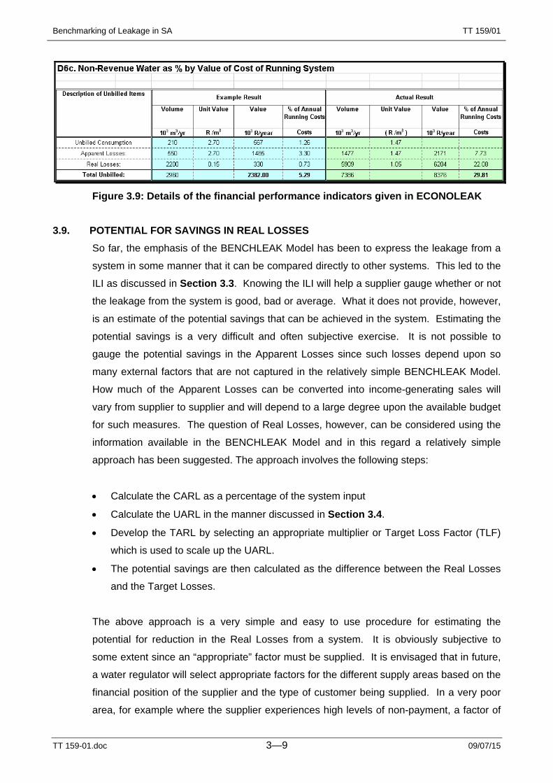
provided in Section D6c of the ECONOLEAK Model and are shown in Fig. 3.9.
From the sample values shown in Figs. 3.9 and 3.7, it can be seen that the performance
indicators are significantly different when expressed in terms of percentage of system
input and percentage of system running costs. Both measures are useful under certain
circumstances.
Benchmarking of Leakage in SA
TT 159-01.doc 3—9 09/07/15
TT 159/01
Figure 3.9: Details of the financial performance indicators given in ECONOLEAK
3.9. POTENTIAL FOR SAVINGS IN REAL LOSSES So far, the emphasis of the BENCHLEAK Model has been to express the leakage from a
system in some manner that it can be compared directly to other systems. This led to the
ILI as discussed in Section 3.3. Knowing the ILI will help a supplier gauge whether or not
the leakage from the system is good, bad or average. What it does not provide, however,
is an estimate of the potential savings that can be achieved in the system. Estimating the
potential savings is a very difficult and often subjective exercise. It is not possible to
gauge the potential savings in the Apparent Losses since such losses depend upon so
many external factors that are not captured in the relatively simple BENCHLEAK Model.
How much of the Apparent Losses can be converted into income-generating sales will
vary from supplier to supplier and will depend to a large degree upon the available budget
for such measures. The question of Real Losses, however, can be considered using the
information available in the BENCHLEAK Model and in this regard a relatively simple
approach has been suggested. The approach involves the following steps:
• Calculate the CARL as a percentage of the system input
• Calculate the UARL in the manner discussed in Section 3.4.
• Develop the TARL by selecting an appropriate multiplier or Target Loss Factor (TLF)
which is used to scale up the UARL.
• The potential savings are then calculated as the difference between the Real Losses
and the Target Losses.
The above approach is a very simple and easy to use procedure for estimating the
potential for reduction in the Real Losses from a system. It is obviously subjective to
some extent since an “appropriate” factor must be supplied. It is envisaged that in future,
a water regulator will select appropriate factors for the different supply areas based on the
financial position of the supplier and the type of customer being supplied. In a very poor
area, for example where the supplier experiences high levels of non-payment, a factor of

Benchmarking of Leakage in SA
TT 159-01.doc 3—10 09/07/15
TT 159/01
4 or 5 may be selected until such time as the non-payment is under control. In other
areas where the water supplier has a reliable income base, a lower factor of 2 or 3 may be
appropriate. This approach has yet to be ratified and is simply one possible way of
deriving the potential reduction in Real Losses from an area. The calculation is provided
in Section D7c of the BENCHLEAK Model and the only input required from the user is to
set the Target Loss Factor. Details of the calculation are shown in Fig. 3.10.
Figure 3.10: Estimation of potential savings in Real Leakage in BENCHLEAK
From Fig. 3.10, it can also be seen that the potential level of Real Losses is provided as a
percentage of the system input. Again, this is not considered good practice. However, it
can be used to compare results from the same system in subsequent years in which case
it is permitted to use percentages.
It should be noted that the factor used in Section D7d of the BENCHLEAK Model is a
new concept and it has yet to be fully tested throughout South Africa. The intention is to
provide some methodology for setting a realistic leakage target based on the actual
ground conditions. For example, it is not appropriate to set the same Target Loss Factor
for an affluent area with low leakage as would be selected for an informal area with high
leakage. Until further investigations using BENCHLEAK have been completed, it is
recommended that TLF of between 2 and 5 be selected. A factor of 2 will be used for an
area with relatively low leakage and sound infrastructure while a factor of 5 will be used
for areas with high leakage and poor infrastructure. Eventually it is envisaged that even
the areas with high levels of leakage will be managed properly to reduce leakage, in which
case the Target Loss Factors will gradually be reduced.
3.10. PRESENTATION OF RESULTS Although the spreadsheet is self-explanatory and requires little added information, it was
decided to add some figures as part of the BENCHLEAK Model to assist suppliers in

Benchmarking of Leakage in SA
TT 159-01.doc 3—11 09/07/15
TT 159/01
understanding the different loss components and the potential for saving. In this regard,
two additional figures are provided in Sections 7b and 7e of the BENCHLEAK Model.
The first figure simply presents details of the different components of the water balance
(see Section 3.1) in terms of litres/service connection per day. These units are often
used when checking on the validity of the data and the values obtained can often highlight
problem areas. A typical example is shown in Fig. 3.11 and it should be noted that the
size of the compartment for each element in the water balance is not to scale.
Figure 3.11: Figure showing the overall water balance in BENCHLEAK
The second figure provided in the BENCHLEAK Model is more complicated and helps to
portray a very important concept that is often overlooked. As mentioned in Section 3.1,
the percentage leakage from a system is heavily influenced by the consumption. In many
countries, the leakage is expressed in terms of l/conn/d and so too is the consumption.
Based on this, a set of curves can be prepared which indicate the percentage leakage for
different consumption and real leakage, the latter two of which are expressed in
Litres/service connection per day. This is best explained using the figure provided in the
BENCHLEAK Model. A typical example is shown in Fig. 3.12.
If a system has an average Total Consumption of 4 000 l/conn/d and the Real Leakage is
1 000 l/conn/d, it can be seen from Fig. 3.12 that the Real Losses are 20%. If, however,
the Total Consumption is only 1 000 l/conn/d, then the percentage losses rise to 50%
despite the fact that the real losses have not changed.

Benchmarking of Leakage in SA
TT 159-01.doc 3—12 09/07/15
TT 159/01
This figure can be used to explain why many water services providers will struggle to bring
their leakage levels below 20% or even 30% when their Total Consumption is in the order
of 500 l/conn/d (as is the case in the UK). In countries such as Singapore, however,
where the Total consumption is more than 8 000 l/conn/d due to the high number of
apartment blocks with a single connection, the percentage losses can easily drop to 5% or
below.
Figure 3.12: Curves demonstrating the importance of consumption on % real losses
Suppliers in South Africa tend to operate between Total Consumption of 1 000 to 2 000
l/conn/d. If an acceptable level of leakage is considered to be 200 l/conn/d, the
percentage leakage will lie somewhere between 10% and 20%.
On Fig. 3.12 it can also be seen that the actual Real Losses and the Target Real Losses
are depicted on the chart. The Total Consumption in this example was found to be 1 582
l/conn/d with the result that the two points are fixed on the horizontal at 1 582. In the
example it can be seen that the Real Losses are 23% of the System Input while the target
setting is below 10%. In this example, the potential reduction in leakage is estimated to
be 379 l/conn/d (i.e. more than 18% of system input). The target leakage level is
estimated to be 5% compared to the current leakage level of 23% as can be seen from
Figs. 3.10 and 3.11.

Benchmarking of Leakage in SA
TT 159-01.doc 4—1 09/07/15
TT 159/01
4. USING BENCHLEAK
4.1. HARDWARE AND SOFTWARE REQUIREMENTS In order to run the BENCHLEAK Model the user requires a basic PC with the Windows
operating system and the EXCEL spreadsheet program. If the EXCEL program is not
available, the user can still complete a hard copy of the spreadsheet forms, although the
numerous calculated fields will have to be completed manually when they are normally
calculated automatically by the Excel program. Some users have successfully copied the
spreadsheet onto QUATRO without experiencing any major problems.
4.2. INSTALLING BENCHLEAK The BENCHLEAK Model can be downloaded directly from the WRC web site. It is a
relatively small file at approximately 130K and can be run from anywhere on the user’s PC
as long as the Excel program can be accessed. There is no sophisticated installation
shield and it is simply the case of copying the BENCHLEAK.XLS file into a suitable
directory and using the model in the same manner as a normal Excel spreadsheet.
4.3. DATA REQUIREMENTS The BENCHLEAK Model is colour-coded in such a manner that:
• Yellow blocks must be completed by the user
• Blue blocks simply provide an example data set;
• Green blocks are calculated fields and require no user input.
The user must complete only the yellow blocks which involves the following information:
• System name and contact details (Section D1)
• System data: length of mains, number of connections, percentage of time system is
pressurised and the average operating pressure of the system;
• Period over which the information refers i.e. calendar year, financial year
• Details of water input to the system (i.e. water purchased from bulk supplier and water
produced from own sources etc);
• Details of water supplied to customers including estimates of all unmetered and
unbilled water;
• Estimate of Apparent Losses as a percentage of the total losses.
To facilitate the capture of data from water suppliers, a data request form has been
created that includes only the basic information required. This form is included at the end
of Appendix D.
Benchmarking of Leakage in SA
TT 159-01.doc 5—1 09/07/15
TT 159/01
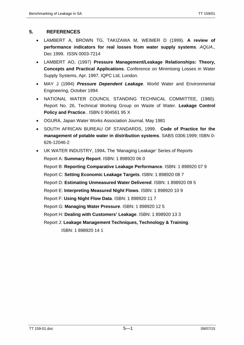
5. REFERENCES • LAMBERT A, BROWN TG, TAKIZAWA M, WEIMER D (1999). A review of
performance indicators for real losses from water supply systems. AQUA., Dec 1999. ISSN 0003-7214
• LAMBERT AO, (1997) Pressure Management/Leakage Relationships: Theory, Concepts and Practical Applications. Conference on Minimising Losses in Water Supply Systems, Apr. 1997. IQPC Ltd, London.
• MAY J (1994) Pressure Dependent Leakage. World Water and Environmental Engineering, October 1994
• NATIONAL WATER COUNCIL STANDING TECHNICAL COMMITTEE, (1980). Report No. 26, Technical Working Group on Waste of Water. Leakage Control Policy and Practice.. ISBN 0 904561 95 X
• OGURA, Japan Water Works Association Journal, May 1981
• SOUTH AFRICAN BUREAU OF STANDARDS, 1999. Code of Practice for the management of potable water in distribution systems. SABS 0306:1999; ISBN 0-626-12046-2
• UK WATER INDUSTRY, 1994. The ‘Managing Leakage’ Series of Reports
Report A: Summary Report. ISBN: 1 898920 06 0
Report B: Reporting Comparative Leakage Performance. ISBN: 1 898920 07 9
Report C: Setting Economic Leakage Targets. ISBN: 1 898920 08 7
Report D: Estimating Unmeasured Water Delivered. ISBN: 1 898920 09 5
Report E: Interpreting Measured Night Flows. ISBN: 1 898920 10 9
Report F: Using Night Flow Data. ISBN: 1 898920 11 7
Report G: Managing Water Pressure. ISBN: 1 898920 12 5
Report H: Dealing with Customers’ Leakage. ISBN: 1 898920 13 3
Report J: Leakage Management Techniques, Technology & Training.
ISBN: 1 898920 14 1

Benchmarking of Leakage in SA
Appendix A 09/07/15
TT 159/01
APPENDIX A
GLOSSARY OF TERMS
Benchmarking of Leakage in SA
Appendix A A - 1 09/07/15
TT 159/01
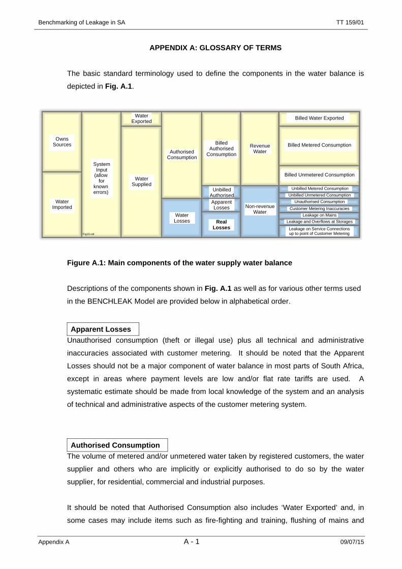
APPENDIX A: GLOSSARY OF TERMS The basic standard terminology used to define the components in the water balance is
depicted in Fig. A.1.
OwnsSources
Water Imported
System Input
(allow for
known errors)
Water Supplied
Water Exported
AuthorisedConsumption
Water Losses
Unbilled AuthorisedApparentLosses
Real Losses
Non-revenueWater
RevenueWater
BilledAuthorised
Consumption
Billed Water Exported
Billed Metered Consumption
Billed Unmetered Consumption
Unbilled Metered ConsumptionUnbilled Unmetered Consumption
Unauthorised ConsumptionCustomer Metering Inaccuracies
Leakage on MainsLeakage and Overflows at Storages
Leakage on Service Connectionsup to point of Customer MeteringFig10.cdr
Figure A.1: Main components of the water supply water balance
Descriptions of the components shown in Fig. A.1 as well as for various other terms used
in the BENCHLEAK Model are provided below in alphabetical order.
Apparent Losses Unauthorised consumption (theft or illegal use) plus all technical and administrative
inaccuracies associated with customer metering. It should be noted that the Apparent
Losses should not be a major component of water balance in most parts of South Africa,
except in areas where payment levels are low and/or flat rate tariffs are used. A
systematic estimate should be made from local knowledge of the system and an analysis
of technical and administrative aspects of the customer metering system.
Authorised Consumption The volume of metered and/or unmetered water taken by registered customers, the water
supplier and others who are implicitly or explicitly authorised to do so by the water
supplier, for residential, commercial and industrial purposes.
It should be noted that Authorised Consumption also includes ‘Water Exported’ and, in
some cases may include items such as fire-fighting and training, flushing of mains and
Benchmarking of Leakage in SA
Appendix A A - 2 09/07/15
TT 159/01
sewers, street cleaning, watering of municipal gardens, public fountains, frost protection,
building water, etc. These may be billed or unbilled, metered or unmetered, according to
local practice.
Average Operating Pressure The average operating pressure for the whole system over the period in question. Details
of the methodology used to calculate the average operating pressure are provided in
Appendix C.
Billed Authorised Consumption The volume of authorised consumption which is billed and paid for. This is effectively the
Revenue Water which, in turn, comprises:
• Billed Water Exported;
• Billed Metered Consumption;
• Billed Unmetered Consumption.
Current Annual Real Losses (CARL) The real losses for the period under consideration expressed in terms of l/conn/d or
m3/year etc. Same as Real Losses.
Infrastructure Leakage Index (ILI) The infrastructure leakage index is a non-dimensional index which provides an indication
of how serious the leakage occurring in a particular area is compared to the theoretical
minimum level of leakage that can be achieved. The ILI is defined as:
ILI = CARL / UARL
Length of Mains (Lm) The length of mains is the total length of bulk and distribution mains in a particular system.
All pipes excluding the connection pipes are considered to be mains. The length of mains
is normally given in km.

Benchmarking of Leakage in SA
Appendix A A - 3 09/07/15
TT 159/01
Non-Revenue Water The Non-Revenue Water is becoming the standard term replacing Unaccounted-for Water
in many water balance calculations. It is a term that can be clearly defined, unlike the
Unaccounted-for Water term which often represents different components to the various
water suppliers. Non-Revenue Water incorporates the following items:
• Unbilled Authorised Consumption;
• Apparent Losses; and
• Real Losses.
The above terms can be further sub-divided into the following;
• Unbilled Metered Consumption;
• Unbilled Unmetered Consumption;
• Unauthorised Consumption (theft);
• Customer meter inaccuracies;
• Mains leakage;
• Overflow leakage from storage facilities;
• Connection leakage before customer meter.
Number of Service Connections (Ns) The number of connections to the mains. In cases where one saddle connection
branches to two or more erf connections, the number of erfs (not properties) can be used.
Real Losses Physical water losses from the pressurised system, up to the point of measurement of
customer use. Calculated as:
‘System Input’ – (‘Authorised Consumption’ + ‘Apparent Losses’)
The annual volume lost through all types of leaks, bursts and overflows depends on
frequencies, flow rates, and average duration of individual leaks.

Benchmarking of Leakage in SA
Appendix A A - 4 09/07/15
TT 159/01
System Input The volume input to that part of the water supply system to which the water balance
calculation relates, allowing for known errors. Equal to:
• ‘Own Sources’ + ‘Water Imported’
• ‘Water Exported’ + ‘Water Supplied’
• ‘Authorised Consumption’ + ‘Water Losses’
Total Consumption Total consumption is the sum of the following three components:
• Billed authorised consumption
• Unbilled authorised consumption
• Apparent losses.
Target Annual Real Loss (TARL) The target annual real loss is the level of real losses that a particular water supplier
considers to be appropriate for their system. The TARL can be estimated from the UARL
using a simple multiplier. For example, a water supplier in South Africa may judge that a
realistic target level may be three times the theoretical minimum level in which case the
TARL would simply be set to three times the UARL.
Total Losses Total losses are the sum of the real and apparent losses
Unavoidable Annual Real Losses (UARL) The minimum level of real losses for a specific system that can be achieved under the
most efficient operating conditions. It is an indication of the level of leakage that can
theoretically be achieved if everything possible is done to minimise the leakage and is
generally not an achievable target for most water suppliers since the UARL is normally
well below the economic level of leakage.
Unbilled Authorised Consumption The volume of authorised consumption that is not billed or paid for.
Water Losses The sum of the Real and Apparent losses.

Benchmarking of Leakage in SA
Appendix B 09/07/15
TT 159/01
APPENDIX B
Introduction to BABE and FAVAD Concepts, and Calculation of
Unavoidable Annual Real Losses
Benchmarking of Leakage in SA
Appendix B B - 1 09/07/15
TT 159/01
APPENDIX B: INTRODUCTION TO BABE AND FAVAD CONCEPTS, AND CALCULATION OF UNAVOIDABLE ANNUAL REAL LOSSES
B1: HISTORICAL BACKGROUND As a result of the privatisation of the England & Wales Water Service Companies in
1989, it became necessary for all water suppliers to be able to demonstrate to their
regulators that they fully understood their position on leakage. This did not imply
that all water suppliers had to achieve the lowest possible leakage levels, but simply
that correct and appropriate technical and economic principles were being applied to
leakage management.
Accordingly, in 1990 a National Leakage Control Initiative (NLCI) was established in
England & Wales by the Water Services Association and the Water Companies
Association, to update and review the ‘Report 26’ guidelines (NWCSTC, 1980) for
leakage control that had been in use in the UK since 1980. Considerable progress
that had been made in equipment and metering technology over the previous ten-
year period, but methods of data analysis had not kept pace with these technical
improvements.
In order to co-ordinate the various research efforts described in the ‘Managing
Leakage’ Reports (UK Water Industry, 1994), Mr Allan Lambert, then Technical
Secretary of the NLCI, developed an overview concept of components of real
losses, and the parameters which influence them. This concept, based on
internationally-applicable principles, is known as the Burst and Background
Estimates (BABE) methodology. The BABE concepts were first applied and
calibrated in the UK, and three simple pieces of standard software using the BABE
concepts were made available at the time of issue, in 1994, of the ‘Managing
Leakage’ Reports.
Prior to 1994, a single relationship between minimum night flow and pressure was
normally assumed in the UK, based on the ‘Leakage Index’ curve in Report 26. The
1994 ‘Managing Pressure’ Report recognised that there was not a single
relationship, but did not offer an alternative method. However, a much improved
understanding of the range of relationships between pressure and leakage rate was
introduced separately from the ‘Managing Leakage’ Reports in 1994, when John
May published his FAVAD (Fixed and Variable Areas Discharges) concept
(May, 1994). Using FAVAD, it has been possible to reconcile apparently diverse

Benchmarking of Leakage in SA
Appendix B B - 2 09/07/15
TT 159/01
relationships and data from laboratory tests and distribution sector tests in Japan,
UK, Brazil, Saudi Arabia, and Malaysia,
Since 1994, the BABE and FAVAD concepts have been applied in many countries
for the solution of a wide range of leakage management problems.
Fig. B.1 shows the typical range of problems that can be successfully tackled with
these concepts. The remainder of this Appendix explains the application of BABE
and FAVAD concepts to the development of the International Performance
Indicators for Real Losses.
Figure B.1: Problem-Solving using BABE and FAVAD concepts
B2: BURST AND BACKGROUND ESTIMATE (BABE) procedures In order to address leakage it was considered necessary to first understand the
various components making up the water balance for a typical water supply network.
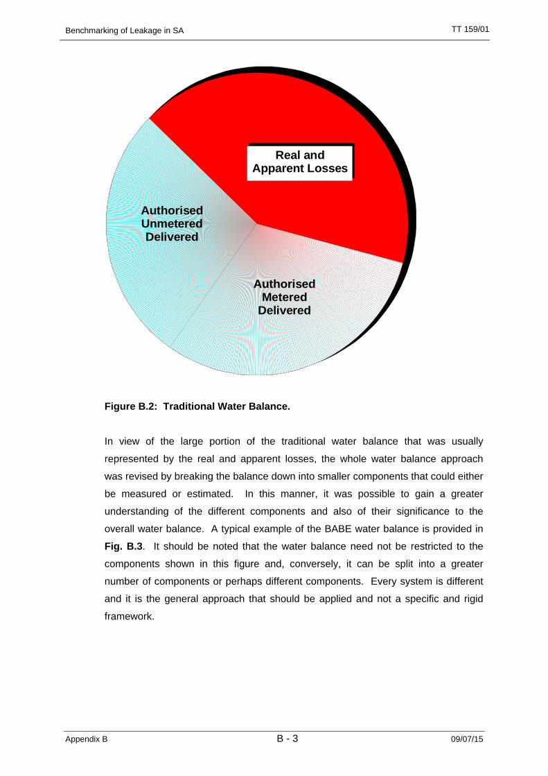
The previous approach as shown in Fig. B.2 was to consider three main
components: Authorised Metered, Authorised Unmetered and the remainder which
represents all unaccounted-for water, and is often referred to as the real and
apparent losses. Further details on real and apparent losses are provided later in
this section and are also shown in Fig. B.4.
Benchmarking of Leakage in SA
Appendix B B - 3 09/07/15
TT 159/01
AuthorisedUnmeteredDelivered
Authorised Metered
Delivered
Real and Apparent Losses
Figure B.2: Traditional Water Balance.
In view of the large portion of the traditional water balance that was usually
represented by the real and apparent losses, the whole water balance approach
was revised by breaking the balance down into smaller components that could either
be measured or estimated. In this manner, it was possible to gain a greater
understanding of the different components and also of their significance to the
overall water balance. A typical example of the BABE water balance is provided in
Fig. B.3. It should be noted that the water balance need not be restricted to the
components shown in this figure and, conversely, it can be split into a greater
number of components or perhaps different components. Every system is different
and it is the general approach that should be applied and not a specific and rigid
framework.
Benchmarking of Leakage in SA
Appendix B B - 4 09/07/15
TT 159/01
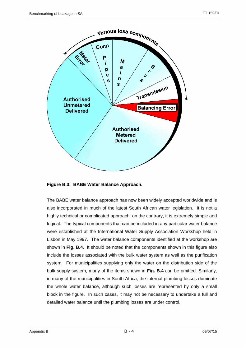
Figure B.3: BABE Water Balance Approach.
The BABE water balance approach has now been widely accepted worldwide and is
also incorporated in much of the latest South African water legislation. It is not a
highly technical or complicated approach; on the contrary, it is extremely simple and
logical. The typical components that can be included in any particular water balance
were established at the International Water Supply Association Workshop held in
Lisbon in May 1997. The water balance components identified at the workshop are
shown in Fig. B.4. It should be noted that the components shown in this figure also
include the losses associated with the bulk water system as well as the purification
system. For municipalities supplying only the water on the distribution side of the
bulk supply system, many of the items shown in Fig. B.4 can be omitted. Similarly,
in many of the municipalities in South Africa, the internal plumbing losses dominate
the whole water balance, although such losses are represented by only a small
block in the figure. In such cases, it may not be necessary to undertake a full and
detailed water balance until the plumbing losses are under control.

Benchmarking of Leakage in SA
Appendix B B - 5 09/07/15
TT 159/01
Figure B.4: Recommended BABE Water Balance Components.
Fig. B.4 provides a breakdown of the most important components that can be
included in a water balance for a specific water supplier. It is important to note that
the losses have been broken down into real and apparent losses. Real losses are
those where the water has left the system and has not been utilised in any way. If
such losses can be reduced, the total water required by the supplier will also be
reduced. Apparent losses, on the other hand, are simply “paper” losses that do not
represent a loss from the system. They are usually due to illegal connections, and
meter and billing errors. If such losses are eliminated, the total water required by
the supplier may not change. However, the “unaccounted-for” component in the
water balance will be reduced. In such, cases certain other components such as
“Authorised Metered” or even “Authorised Unmetered” will increase as the apparent
losses are reduced.
B3: WHAT ARE BURST AND BACKGROUND LEAKS ? The larger detectable events are referred to as bursts, while those too small to be
located (if not visible) are referred to as background leaks. The threshold between
bursts and background leaks can vary from country to country, depending on factors
such as minimum depth of pipes, type of ground and surface, etc. In the UK a
threshold limit of 500 l/h was used in the 1994 Managing Leakage Reports, but
Benchmarking of Leakage in SA
Appendix B B - 6 09/07/15
TT 159/01
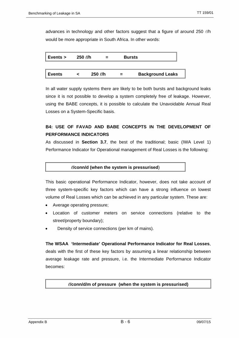
advances in technology and other factors suggest that a figure of around 250 l/h
would be more appropriate in South Africa. In other words:
Events > 250 l/h = Bursts
Events < 250 l/h = Background Leaks
In all water supply systems there are likely to be both bursts and background leaks
since it is not possible to develop a system completely free of leakage. However,
using the BABE concepts, it is possible to calculate the Unavoidable Annual Real
Losses on a System-Specific basis.
B4: USE OF FAVAD AND BABE CONCEPTS IN THE DEVELOPMENT OF PERFORMANCE INDICATORS As discussed in Section 3.7, the best of the traditional; basic (IWA Level 1)
Performance Indicator for Operational management of Real Losses is the following:
l/conn/d (when the system is pressurised)
This basic operational Performance Indicator, however, does not take account of
three system-specific key factors which can have a strong influence on lowest
volume of Real Losses which can be achieved in any particular system. These are:
• Average operating pressure;
• Location of customer meters on service connections (relative to the
street/property boundary);
• Density of service connections (per km of mains).
The WSAA ‘Intermediate’ Operational Performance Indicator for Real Losses,
deals with the first of these key factors by assuming a linear relationship between
average leakage rate and pressure, i.e. the Intermediate Performance Indicator
becomes:
l/conn/d/m of pressure (when the system is pressurised)

Benchmarking of Leakage in SA
Appendix B B - 7 09/07/15
TT 159/01
The justification for this assumption can be explained using the FAVAD concept. In
its’ simplest form; this assumes that leakage rate (L) varies with Pressure (P) to the
power N1, i.e.
L varies with PN1
International research has shown that different types of leakage paths have different
values of N1, which can range from 0.5 to 2.5. Values of N1 derived from tests on
small sectors of distribution systems are usually in the range 0.5 to 1.5. When a
weighted average of these N1 values is calculated, for application to larger
distribution systems, the average N1 value is usually quite close to 1.0 (see Ogura, 1981 and Lambert, 1997), i.e. a linear relationship can be assumed.
The ‘Intermediate’ Operational Performance Indicator does not, however, deal with
the second and third of the system-specific key factors which can influence the
lowest volume of Real Losses which can be achieved in any particular system, i.e.
• Location of customer meters on service connections (relative to street/property
boundary);
• Density of service connections (per km of mains).
The ‘Detailed’ Operational Performance Indicators for Real Losses, deals with
both these factors, and average operating pressure, by calculating a system-specific
value for ‘Unavoidable Annual Real Losses’ (UARL). The ratio of the Current Annual
Real Losses (CARL, calculated from the standard Water Balance) to the UARL, is
the Infrastructure Leakage Index (ILI), i.e.
Infrastructure Leakage Index ILI = CARL/UARL
The equation for UARL is based on BABE concepts, using auditable assumptions.
With BABE concepts, it is possible to calculate, from first principles, the components
which make up the annual volume of Real Losses. This is because the leaks
occurring in any water supply system can be considered conceptually in three
categories:
• Background leakage – small undetectable leaks at joints and fittings;
• Reported bursts – events with larger flows which cause problems and are
reported to the water supplier;

Benchmarking of Leakage in SA
Appendix B B - 8 09/07/15
TT 159/01
• Unreported bursts – significant events that do not cause problems and can only
be found by active leakage control.
B5: CALCULATION OF UNAVOIDABLE ANNUAL REAL LOSSES (UARL) The procedure to estimate the UARL was developed by Lambert during the period
of the International Water Association’s Task Force on Water Losses. The
methodology is described in a paper in AQUA (Lambert et.al, 1999) and involves
estimating the unavoidable losses for three components of infrastructure, namely:
• Transmission and distribution mains (excluding service connections);
• Service connections, mains to street/property boundary;
• Private underground pipe between street/property boundary and customer
meter.
In South Africa, the third of these components can normally be ignored since
customer meters are located close to the edge of the street.
The parameters used in the calculation of the losses are indicated in Table B1.
From this table it can be seen that the one variable common to all elements is
pressure. This is also the one variable that is normally excluded from most
commonly used leakage performance indicators such as percentage, leakage per
connection per year and leakage per km of mains per year.
Table B1: Parameters required for the calculation of UARL
Component of Infrastructure
Background Losses
Reported Bursts
Unreported bursts
Mains • Length • Pressure
• Minimum loss rate/km*
• Number/year • Pressure
• Average flow rate* • Average duration
• Number/year • Pressure
• Average flow rate • Average duration
Service connections to street/property line
• Number • Pressure • Minimum loss rate/conn*
• Number/year • Pressure • Average flow rate* • Average duration
• Number/year • Pressure • Average flow rate • Average duration
Service connections after street/property line
• Length • Pressure
• Minimum loss rate/km*
• Number/year • Pressure
• Average flow rate* • Average duration
• Number/year • Pressure
• Average flow rate • Average duration
* these flow rates are initially specified at 50m pressure

Benchmarking of Leakage in SA
Appendix B B - 9 09/07/15
TT 159/01
Each of the elements in Table B1 can be allocated a value appropriate to
infrastructure in good condition, operated in accordance with best practice, based on
the analysis of data from numerous systems throughout the world. The results are
provided in Table B2. It should be noted that the general guideline for infrastructure
replacement is in the order of 2% per annum. In the South African context, this
figure is too high and a more realistic value of between 0.25% and 0.5% is
applicable due to the severe financial constraints placed on most of the country’s
water suppliers.
Table B2: Parameter values used to calculate UARL
Component of Infrastructure
Background Losses
Reported Bursts
Unreported Bursts
Mains 20*
l/km/h
• 0.124 bursts /km/year at • 12 m3/h per burst*
• average duration of 3 d
• 0.006 bursts /km/year at • 6 m3/h per burst*
• average duration of 50 d
Service connections to street/property line
1.25*
l/conn/h
• 2.25/1000 connections/year at
• 1.6 m3/h per burst* • average duration of 8 d
• 0.75/1000 conn/yr at
• 1.6 m3/h per burst* • average duration of 100 d
Unmetered Service connections after street/property line
0.50*
l/conn/h per 15 m length
• 1.5/1000 connections/year at
• 1.6 m3/h per burst* • average duration of 9 d
• 0.50/1000 conn/yr at • 1.6 m3/h per burst*
• average duration of 101 d
* these flow rates are initially specified at 50m pressure
The parameter values indicated in Table B2 include data for minimum background
loss rates and typical burst frequencies for infrastructure in good condition, and for
typical average flow rates of bursts and background leakage at 50m pressure. The
average duration assumed for reported bursts is based on best practice world-wide.
The average duration for unreported bursts is based on intensive active leakage
control, approximating to night flow measurements once per month on highly
sectorised water distribution systems.
Methods for calculating the average pressure in the system under consideration are
explained in Appendix C.
Assuming a simplified linear relationship between leakage rate and pressure, the
components of UARL can be expressed in modular form, for ease of calculation, as
shown in Table B3. Sensitivity testing shows that differences in assumptions for

Benchmarking of Leakage in SA
Appendix B B - 10 09/07/15
TT 159/01
parameters used in the ‘Bursts’ components have relatively little influence on the
‘Total UARL’ values in the 5th column of Table B3.
Table B3: Calculated Components of Unavoidable Annual Real Losses (UARL)
Component of Infrastructure
Background Losses
Reported Bursts
UnreportedBursts
Total UARL
Units
Mains 9.6 5.8 2.6 18 l/km mains/d per m of pressure
Service connections to
street/property line
0.60 .04 0.16 0.8 l/conn/d/ m of pressure
Unmetered Service connections after
street/property line
16.0 1.9 7.1 25 l/km underground. pipe/d/m of pressure
NOTE: the UARL from Unmetered Service Connections after the street/property line can be ignored in the South
African context, as all customers are metered and these meters are located close to the street/property line. This
component of UARL has not, therefore, been included in the BENCHLEAK software. The losses from the service
connections (main to meter) tend to dominate the calculation of UARL in most parts of South Africa, except at low
density of connections (less than 20 per km of mains).
Based on the figures provided in Table B3, the calculation of the UARL can be
expressed as follows:
UARL = (18 * Lm + 0.80 * Nc + 25 * Lp) * P
Where:
UARL = Unavoidable annual real losses (l/d) Lm = Length of mains (km) Nc = Number of service connections (main to meter) Lp = Length of unmetered underground pipe from street edge to customer
meters (km) P = Average operating pressure at average zone point (m)
Example: A system has 114 km of mains, 3920 service connections all located at
the street property boundary edge and an average operating pressure of 50 m.
UARL = (18 * 114 + 0.80 * 3920 + 25 * 0) * 50 l/d = 102 600 + 156 800 l/d = 259 400 l/d = 259.4 m3/d = 94 681 m3/yr = 66 l/conn/d

Benchmarking of Leakage in SA
Appendix C 09/07/15
TT 159/01
APPENDIX C
Methods Of Calculating Average Pressure In Distribution Systems

Benchmarking of Leakage in SA
Appendix C C - 1 09/07/15
TT 159/01
APPENDIX C: METHODS OF CALCULATING AVERAGE PRESSURE IN DISTRIBUTION SYSTEMS
C1: A SYSTEMATIC APPROACH TO CALCULATING AVERAGE PRESSURE As pressure is a key parameter in modelling and understanding leakage, it is
worthwhile to adopt a systematic approach to its calculation. The procedure is as
follows:
• For each individual zone or sector, calculate the weighted average ground level;
• Near the centre of the zone, identify a convenient pressure measurement point
which has the same weighted average ground level – this is known as the
Average Zone Point;
• Measure the pressure at the Average Zone Point, and use this as the surrogate
average pressure for the Zone.
AZP pressures should be calculated as average 24-hour values; night pressures at
the AZP point are known as AZNP’s (Average Zone Night Pressures).
For relatively small sectors with well-sized mains in good condition, with reliable
information on average Zone inlet pressure at a single inlet point, preliminary
estimates of average pressure can be made as follows:
• Measure or estimate the average pressure at the Inlet Point to the zone or
sector, and estimate the average zone pressure, taking into account the
difference in datum levels between the Inlet Point and the AZP point, assuming
no frictional loss.
To obtain Average Pressure for aggregations of Zones, calculate the weighted
average value of pressure using (preferably) number of service connections in each
zone.
If Network Analysis models are not available, the approach used in part B2 of this
Appendix should be followed. If Network Analysis models are available, follow the
approach in Section C3.

Benchmarking of Leakage in SA
Appendix C C - 2 09/07/15
TT 159/01
C2. AVERAGE ZONE PRESSURES WHERE NO NETWORK MODELS EXIST C2.1 Calculate Weighted Average Ground Level for Each Sector Split the distribution system conceptually into sectors defined by pressure
management zones or district metered areas; break the system down into the
smallest areas for which average pressures may be required.
Next, for each sector, superimpose a plan of the distribution system over a contour
map, preferably with 2-metre intervals. Allocate to each contour band one of the
following infrastructure parameters (parameters are in order of preference):
• Number of service connections;
• Number of hydrants;
• Length of mains.
Whichever infrastructure parameter is selected, the weighted average ground level
can then be calculated as shown in Table C1 below.
Table C1: Example calculation of weighted ground level
Contour Band (m) Number of Service
Connections
Contour Band Mid Point * Number of
Connections Lower Limit Upper Limit Mid-Band
2.0 4.0 3.0 18 54
4.0 6.0 5.0 43 215
6.0 8.0 7.0 40 280
8.0 10.0 9.0 41 369
10.0 12.0 11.0 63 693
12.0 14.0 13.0 70 910
14.0 16.0 15.0 41 615
16.0 18.0 17.0 18 306
18.0 20.0 19.0 12 228
20.0 22.0 21.0 8 168
22.0 24.0 23.0 3 69
24.0 26.0 25.0 0 0
Totals 357 3907
Weighted Average Ground Level = 3907 / 357 = 10.9 m

Benchmarking of Leakage in SA
Appendix C C - 3 09/07/15
TT 159/01
C2.2 Measure or Calculate Average Zone Pressure Obtain the average pressure at the Average Zone Point in the following manner:
• Measurements over a period of one year;
• Preliminary estimate based on average Inlet pressure adjusted for difference in
ground levels between Inlet Point and AZP.
Example: In the sector data in Table C1, the average inlet pressure at a service
reservoir is 1.5 m below the overflow level (which is 65.0 m above sea level).
• The average inlet pressure is (65.0 – 1.5) = 63.5 m above sea level;
• The ground level at the AZP point is 10.9 m above sea level;
• The average zone pressure is therefore estimated as (63.5 – 10.9) =
43.6 m.
C2.3 Calculate Weighted Average Pressure for Aggregation of Zones The weighted average pressure for sectors of a distribution system, consisting of
aggregations of individual zones with different average pressures, is obtained by
calculating a weighted average for all the zones. If possible, the Number of Service
Connections should be used as the weighting parameter (if not available, use length
of mains or number of hydrants). An example calculation is shown in Table C2.
Table C2: Example calculation of weighted ground level
Area Reference
Number of Service Connections
Average Zone Pressure
Number of service
Connections * AZP
A 420 55.5 23 310 B 527 59.1 31 146 C 443 69.1 30 611 D 1352 73.3 99 102 E 225 64.1 14 423 F 837 42.0 35 154 G 1109 63.7 70 643 H 499 56.3 28 094 I 1520 57.0 86 640
6932 419 122
Weighted average pressure for the whole area = 419,122/6932 = 60.5 m
Benchmarking of Leakage in SA
Appendix C C - 4 09/07/15
TT 159/01
C3. AVERAGE ZONE PRESSURES USING NETWORK MODELS C3.1 Calculate Weighted Average Ground Level for Each Sector Because each node of a Network Analysis Model will normally have a number of
properties, a datum ground level, and an average pressure value, it is relatively easy
to calculate the weighted average pressure for all the nodes in the model (or any
defined part of it).
It is worthwhile, however, to ensure that a weighted average ground level, and an
AZP point are defined for each zone/sector, as these will occasionally be required
for test measurement.

Benchmarking of Leakage in SA
Appendix D 09/07/15
TT 159/01
APPENDIX D
• Example of completed BENCHLEAK Form
• Listing of Data Request Form

Benchmarking of Leakage in SA
Appendix E 09/07/15
TT 159/01
APPENDIX E
BENCHMARKING REAL WATER LEAKAGE IN SOUTH AFRICA: RESULTS AND ANALYSIS OF
LOCAL AUTHORITIES DATA USING BENCHLEAK

Benchmarking of Leakage in SA
Appendix E E - 1 09/07/15
TT 159/01
BENCHMARKING REAL WATER LEAKAGE IN SOUTH
AFRICA: RESULTS AND ANALYSIS OF LOCAL AUTHORITIES DATA USING BENCHLEAK
Executive Summary
Until recently (mid 1990’s) no standard methodology or terminology for the calculation of water
losses existed. Misunderstandings and problems arose often because of differences in the
definitions and methods used by different people in different parts of the world to calculate and
describe water losses. National and international comparisons of the performance of a system
cannot be made in the absence of standard terminology and methodology to calculate and
describe losses. The main issue to be addressed is how leakage and losses should be calculated
to provide meaningful results and what performance indicators should be used to allow meaningful
comparison of leakage between different systems.
The South African Water Supply Industry has undergone some dramatic changes in recent years.
Not only did the industry see numerous changes in the institutional arrangements, but the
emphasis of demand and supply has also changed. Local authorities are becoming more
autonomous, with the result that more of the responsibilities from the national government bodies
are being transferred to the local authorities.
As part of the Benchmarking of Leakage project undertaken for the Water Research Commission
(WRC), it was decided to carry out a number of case studies to assess the ease-of-use of the
BENCHLEAK Model and also to gain a perspective on the level of leakage in South African water
reticulation networks. Water suppliers across all categories and throughout South Africa were
contacted and invited to participate in this study. To facilitate the capture of data from water
suppliers, a data request form was created that includes the basic information required. The data
request form was sent to water suppliers and the BENCHLEAK model was sent to those with
access to the MS Excel program. Most water suppliers could not complete the form within the
required four-week period due to the required information not being readily available and also due
to a lack of resources.
It is important to note that the study was carried out before the new 2001 municipal demarcation
and the water suppliers therefore relate to the former municipal areas. The total number of forms
sent out represented approximately 10% of the total number of water suppliers in South Africa.
They included Transitional Local Councils (TLCs), Transitional Rural Councils (TRCs), Regional
Benchmarking of Leakage in SA
Appendix E E - 2 09/07/15
TT 159/01
Councils (RCs), District Councils (DCs) and Metropolitan Local Councils (MLCs). Of the total
number of forms sent out, approximately 60% were returned from which only 85% were finally
selected after detailed screening. The other 15% were rejected due to anomalous data. The final
selected entities represented about 4% of the total number of water suppliers in South Africa. It is
interesting to note that all the MLC’s contacted responded positively to the request for data and
most were very interested in receiving feedback from the project team.
In order to validate the results, the data were thoroughly checked for any obvious anomalies.
Numerous mistakes and incorrect data were identified during this screening process. In cases
where dubious date were identified the water supplier was contacted again to verify the data. While
most of the large errors were identified, there are still likely to be other less obvious errors which
can only be identified through thorough and regular completion of the BENCHLEAK form. Typical
errors and mistakes identified included:
• Mistakes related to the units of the input data.
• Errors in the input data, e.g. Authorised Consumption equal or more than the Input Volume.
• Where parts of the supply area are excluded from certain data, but included in other data,
e.g. a certain area would be metered by one bulk meter only and would be included in the
System Input Volume but not in the Authorised Consumption since individual consumers
are not metered.
• Inaccurate or incorrect data leading to unrealistic results, e.g. where the inputs to Length of
Mains and Number of Service Connections results in a Density of Service Connections of
200 conn/ km of mains. This would suggest a property every 10 m on both sides of the road
which is unrealistic in South Africa.
One of the key concepts on which the BENCHLEAK Model is based concerns the development of
a method to estimate the minimum level of leakage for any given water distribution system. This
theoretical lowest possible achievable annual volume of Real Losses is termed the Unavoidable
Annual Real Losses (UARL). While the calculation of the minimum level of leakage for a system
initially appears very simple and almost empirical, it is in fact based on considerable research and
factual information taken from many of the best-managed water supply systems throughout the
world.
Another key concept is the introduction of a new performance indicator which can be used to
gauge the level of leakage in any given system. This is termed the Infrastructure Leakage Index
(ILI), which is a non-dimensional index that compares the current real leakage to the theoretical
minimum level of leakage that can be achieved. The ILI therefore provides an indicator of the
current level of leakage management in the particular system in relation to the (absolute) minimum
level of leakage. A high ILI value indicates poor performance with large potential for improvement,

Benchmarking of Leakage in SA
Appendix E E - 3 09/07/15
TT 159/01
while a small ILI value indicates a well-managed system with little scope for improvement. The
index would normally be expected to range form 1.0 (excellent) to in excess of 10.0 (poor). In
South Africa it is unusual to achieve an ILI value of below 2.0 and values in the order of 5.0 are
common which represent systems in a reasonable condition with some scope for improvement.
The key performance indicators for the case study are provided in Table 1.
Table 1: Key Performance Indicators
Utility Ref No. Unavoidable Annual Real Losses Infrastructure Leakage Index (Ml/yr) (l/conn/d)
Group 1 – Large (No of service connections > 50 000)1 6 086 53 6.22 4 510 44 5.23 2 722 46 4.24 3 322 57 3.05 3 202 83 5.26 1 576 41 2.67 3 526 121 9.18 1 237 48 5.49 1 452 58 2.9
10 1 752 70 4.311 1 682 77 10.212 1 083 51 3.4
Group Ave 2 679 62 5.1Group 2 – Medium (10 000 < No of service connections < 50 000)
13 860 50 2.214 604 39 4.615 499 38 11.816 722 58 3.717 776 66 4.318 829 73 4.419 349 53 9.420 305 51 1.921 190 49 17.522 275 73 19.8
Group Ave 541 55 8.0Group 3 – Small (No of service connections < 10 000)
23 203 58 2.924 165 49 6.425 119 37 2.026 120 56 3.727 113 73 10.028 124 85 2.729 39 40 6.530 33 50 9.431 28 58 4.432 21 40 11.333 26 73 1.034 7 74 17.0
Group Ave 83 58 6.4Sample Ave 1 134 59 6.4

Benchmarking of Leakage in SA
Appendix E E - 4 09/07/15
TT 159/01
From examination of the completed case study forms, the following conclusions can be drawn:
• The South African water supply industry is generally lagging best international practices
with respect to leakage management in potable water distribution systems. It was only
during 1996 that the Water Research Commission (WRC) identified the need to control the
level of unaccounted-for water in South Africa with the result that the development of a
standard methodology or terminology for the calculation of water losses was only initiated in
the late 1990’s.
• The information required to calculate the various performance indicators used in this case
study is often not available from the water suppliers despite the fact that the information is
very basic. For example, many water suppliers have difficulties in providing information
such as the total length of mains and number of service connections in their system.
• While the benchmarking procedure was initially developed for complete water distribution
systems, the same approach can easily be used for individual management zones within a
single supply system. In this manner this approach can be used to identify problem
management zones within a system as well as to compare one system with another.
• Water supply systems in South Africa are poorly metered with regard to both bulk and
consumer metering.
• Of the total sample group consisting of 34 local councils, 35% have more than 50 000
service connections (Group 1), 30% have less than 50 000 but more than 10 000
connections (Group 2) and 35% have less than 10 000 service connections (Group 3). The
sample group is considered to be representative of local councils in South Africa. Since the
sample group contains all of the Metropolitan Local Councils, making up the majority but
not 100% of Group 1, it is evident that most supply systems in the country would typically
have less than 50 000 connections.
• In the respective groupings, 100% of cases in Group 1 has mains in excess of 1 000 km,
90% of cases in Group 2 has mains less than 1 000 km but more than 300 km, while in
Group 3 80% of cases has mains less than 300 km. It is evident that most supply systems
in the country would typically have less than 1 000 km of mains, while very few would have
a total length of mains less than 10 km.
• No conclusive remarks can be made with regard to the density of connections in relation to
the size of the distribution system until more data are collected and analysed for supply
systems in South Africa. The average density of connections for Group 1, Group 2 and
Group 3 are 57, 52 and 38 respectively. Based on this case study, 50 connections per km
of mains is considered to be an average value for supply systems. Few systems have a
density of less than 20 connections/ km or more than 100 connections/ km of mains.
• For Group 1 System Input Volume is typically more than 25 000 Ml/yr, while for Group 2 it
is typically more than 10 000 Ml/yr. Water systems in Group 3 typically reported System
Benchmarking of Leakage in SA
Appendix E E - 5 09/07/15
TT 159/01
Input Volume of more than 1 000 Ml/yr, but less than 10 000 Ml/yr. The distribution within
the respective groups is erratic and displays a larger variance. This is simply because
System Input Volume is not directly proportional to system size. The average System Input
Volume for the total sample group is about 36 000 Ml/yr (or 36 x 106 m3/ yr). Assuming that
there are approximately 300 municipalities in the country (under the new demarcation
system), it means that the total System Input Volume in the country is approximately
11 000 x 106 m3/ yr, almost as much as the mean annual runoff (MAR) of the Orange-Vaal
River system (approximately 12 000 x 106 m3/ yr).
• In terms of Authorised Consumption, Groups 1, 2 and 3 typically reported values of more
than 20 000 Ml/yr, between 20 000 Ml/yr and 6 000 Ml/yr, and between 6 000 Ml/yr and
200 Ml/yr, respectively. The average for the total sample group is approximately
29 000 Ml/yr (or 29 x 106 m3/ yr). If this figure is assumed to be representative of the 300
municipalities in the country, it suggests that the total water used could be as high as 40
times the Authorised Consumption for Durban Metro or more than 25 times the water
supplied by Rand Water.
• Group 1 displays the largest Total Losses (more than 5 000 Ml/yr) followed by Group 2
(more than 1 500 Ml/yr) and Group 3 (less than 1500 Ml/yr). The average Total Losses for
Groups 1, 2, 3 and the total sample group is 18 000, 4 000, 500 and 8 000 Ml/yr
respectively. The losses in the Group 1 systems are of particular concern since they
represent the average System Input Volume of 19 000 Ml/yr for Group 2. Similarly, the
Group 2 Total Losses are almost equal to the average System Input Volume for Group 3 of
4 000 Ml/yr.
• Apparent Losses for Group 1 ranges from about 860 Ml/yr to about 9 380 Ml/yr with an
average of about 3 570 Ml/yr. For Group 2 it ranges from a minimum of approximately
150 Ml/yr to a maximum of 1 480 Ml/yr with an average of 830 Ml/yr. Group 3 reports
Apparent Losses of minimum, maximum and average of approximately 6 Ml/yr, 280 Ml/yr
and 100 Ml/yr respectively.
• The Real Losses (also termed Current Annual Real Losses or CARL) for Group 1 range
from approximately 3 700 Ml/yr to approximately 37 500 Ml/yr with an average of almost
14 500 Ml/yr. For Group 2 the Real Losses range from less than 600 Ml/yr to a maximum
of 6 000 Ml/yr with an average of 3 300 Ml/yr. Group 3 reports Real Losses of between
25 Ml/yr and 1 100 Ml/yr with an average value of 400 Ml/yr. The median (or 50th
percentile) value of Real Losses for Groups 1, 2 and 3 are approximately 10 700 Ml/yr,
3 300 Ml/yr and 300 Ml/yr respectively. The average Real Losses for the total sample
group is approximately 6 000 Ml/yr (or 6 x 10⁶ m3/ yr). If it is assumed that this average

Benchmarking of Leakage in SA
Appendix E E - 6 09/07/15
TT 159/01
value can be used for the 300 systems for the whole of South Africa this equates to
approximately 1.8 x 10⁹ m3/ yr. If the average selling price of water is accepted to be
R2.00/kl, it suggests that the value of Real Losses throughout South Africa is almost
R3 600 million/ yr. Furthermore, if it is assumed that the average urban water demand in
South Africa is approximately 250 l/c/d, then the Real Losses could supply the daily water
demand of almost 20 million people.
• The average Real Losses per service connection per day for Groups 1, 2 and 3 are 353,
447 and 375l/conn/d respectively. Based on these figures, it is reasonable to assume that
an average of 400 l is lost per connection per day in South African water supply systems.
Almost twice the average urban water demand of 250 l/c/d or almost 4 full domestic baths
every day for every connection!
• Expressing Real Losses per connection shows no definite trends with regard to grouping,
which indicates that it is not biased in terms of system size, system input, unit consumption,
etc. As in the case of CARL per connection/day, expressing Real Losses per kilometre of
mains or per connection per metre of pressure also show no definite trends or distribution
patterns.
• The total Non-Revenue water as percentage of System Input Volume ranges from
approximately 6% to 52%. No definite trends can be identified between the different
groupings and the distribution seems to be almost random. The average percentage for the
groups is almost uniform with 26%, 23% and 21% for Groups 1, 2 and 3 respectively. It is
therefore reasonable to assume that approximately one fifth of water supplied will not
contribute to revenue collection.
• Water Suppliers found it difficult to provide details of the various components of Non-
Revenue water. It is even more difficult for Water Suppliers to provide a break-up of the
components of the Unbilled Authorised portion of Non-Revenue water. 9% of Water
Suppliers could not provide an estimate of the average annual operating cost of the system.
This is a major part of the problem of successful cost recovery for water services.
• No definite trends are evident with regard to the distribution of the Unavoidable Annual Real
Losses (UARL) or the Infrastructure Leakage Index (ILI) for the three groups, proving the
effectiveness of this methodology as an unbiased tool that successfully removes various
influential factors when benchmarking the performance of one system against that of
another.
• The average UARL value for Groups 1, 2 and 3 are 62, 55 and 58 l/conn/d respectively.
Based on this case study, it is considered reasonable to assume that the UARL for South
African systems is in the order of 60 l/conn/d. More data need to be collected and analysed
to add greater confidence to these figures. Accepting that the Real Losses are in the order
Benchmarking of Leakage in SA
Appendix E E - 7 09/07/15
TT 159/01
of 400 l/conn/d, it implies that only 15% of Real Losses per connection are unavoidable
and that the remaining 85% could be recovered.
• The ILI values for the sample group range from 1.0 to approximately 28.0 with an average
value in the order of 7.0. The average values are 5.1, 8.0 and 6.4 for Groups 1, 2 and 3
respectively. This can be compared to ILI values calculated by International Water Data
Comparisons Ltd for 27 supply systems in 19 countries that range from 1.0 to 10.0 with an
average value of 4.2.
• For South African conditions it would be unusual to achieve an ILI value of below 2.0 and
values in the order of 5.0 are common and represent systems in a reasonable condition.
For smaller systems one would expect that since these systems are smaller and easier to
manage, it should be possible to achieve an ILI of 3.0 through improved management
practices. This suggests that there is considerable scope for improvement in Groups 2 and
3, while Group 1 could probably achieve an ILI of about 4.0.
Based on the conclusions from this report, it is recommended that:
• The importance of leakage management should gain greater exposure and emphasis from
water services institutions such as the Water Research Commission and the Department of
Water Affairs and Forestry.
• Water services authorities and providers should be made aware of the existence of the
leakage-benchmarking methodology in order to create an environment of cooperation when
water services institutions embark on further case studies.
• The performance indicators used to benchmark different water suppliers should be chosen
carefully in order to make benchmarking across different categories of service providers or
demarcation areas meaningful.
• Users of the benchmarking model should familiarise themselves fully with the content of the
BENCHLEAK User Guide, before embarking on applying the model.
• The benchmarking model should be compiled into a full database for the South African
water supply industry to facilitate collection and collation of data for an ongoing annual
national benchmarking exercise. The results can then be presented in a standard format
and sent to all water suppliers participating in the exercise. Obviously some of the figures
quoted in this case study are based on a number of broad assumptions and the true
situation can only be established if all of the approximately 300 service providers complete
the BENCHLEAK form. The figures do, however, indicate the possible magnitude of Real
Losses throughout the country.
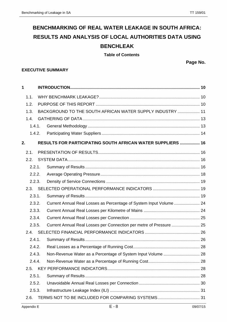
Benchmarking of Leakage in SA
Appendix E E - 8 09/07/15
TT 159/01
BENCHMARKING OF REAL WATER LEAKAGE IN SOUTH AFRICA: RESULTS AND ANALYSIS OF LOCAL AUTHORITIES DATA USING
BENCHLEAK Table of Contents
Page No. EXECUTIVE SUMMARY
1 INTRODUCTION ............................................................................................................... 10
1.1. WHY BENCHMARK LEAKAGE? ...................................................................................... 10 1.2. PURPOSE OF THIS REPORT ......................................................................................... 10 1.3. BACKGROUND TO THE SOUTH AFRICAN WATER SUPPLY INDUSTRY ................... 11 1.4. GATHERING OF DATA .................................................................................................... 13
1.4.1. General Methodology ................................................................................................ 13 1.4.2. Participating Water Suppliers .................................................................................... 14
2. RESULTS FOR PARTICIPATING SOUTH AFRICAN WATER SUPPLIERS ................. 16
2.1. PRESENTATION OF RESULTS ....................................................................................... 16 2.2. SYSTEM DATA ................................................................................................................. 16
2.2.1. Summary of Results .................................................................................................. 16 2.2.2. Average Operating Pressure ..................................................................................... 18 2.2.3. Density of Service Connections ................................................................................ 19
2.3. SELECTED OPERATIONAL PERFORMANCE INDICATORS ........................................ 19 2.3.1. Summary of Results .................................................................................................. 19 2.3.2. Current Annual Real Losses as Percentage of System Input Volume ...................... 24 2.3.3. Current Annual Real Losses per Kilometre of Mains ................................................ 24 2.3.4. Current Annual Real Losses per Connection ............................................................ 25 2.3.5. Current Annual Real Losses per Connection per metre of Pressure ........................ 25
2.4. SELECTED FINANCIAL PERFORMANCE INDICATORS ............................................... 26 2.4.1. Summary of Results .................................................................................................. 26 2.4.2. Real Losses as a Percentage of Running Cost ......................................................... 28 2.4.3. Non-Revenue Water as a Percentage of System Input Volume ............................... 28 2.4.4. Non-Revenue Water as a Percentage of Running Cost ............................................ 28
2.5. KEY PERFORMANCE INDICATORS ............................................................................... 28 2.5.1. Summary of Results .................................................................................................. 28 2.5.2. Unavoidable Annual Real Losses per Connection .................................................... 30 2.5.3. Infrastructure Leakage Index (ILI) ............................................................................. 31
2.6. TERMS NOT TO BE INCLUDED FOR COMPARING SYSTEMS .................................... 31
Benchmarking of Leakage in SA
Appendix E E - 9 09/07/15
TT 159/01
3. CONCLUSIONS AND RECOMMENDATIONS ................................................................ 33
3.1. CONCLUSIONS ................................................................................................................ 33 3.2. RECOMMENDATIONS ..................................................................................................... 34

Benchmarking of Leakage in SA
Appendix E E - 10 09/07/15
TT 159/01
1. INTRODUCTION
1.1. WHY BENCHMARK LEAKAGE? There is a growing realisation that water resources in South Africa are becoming
increasingly stressed in many parts of the country and careful water resources
management is becoming more important. The development of the National Water
Resources Strategy and the Water Conservation and Demand Management National
Strategy by the Department of Water Affairs and Forestry (DWAF), are examples
demonstrating the Government’s commitment to water conservation and the efficient use
of the available resources. As awareness grows internationally about issues such as
sustainability of resources, economic efficiency and protection of the environment, the
leakage from water distribution systems is becoming a topical issue worldwide.
Water losses from water distribution systems are inevitable and cannot be eliminated
completely. Such losses may be due to infrastructure-related problems,
administrative-related problems or theft and usually have financial implications. The
volume of water lost from a system is an indicator of planning and construction efficiency,
distribution efficiency, and operational and maintenance activities. The annual volume of
water lost is therefore an important indicator of the performance of a water supply and
distribution system.
Until recently (mid 1990’s) no standard methodology or terminology for the calculation of
water losses existed. Misunderstandings and problems often arose because of differences
in the definitions and methods used by different people in different parts of the world to
calculate and describe water losses. National and international comparisons of the
performance of a system cannot be made in the absence of standard terminology and
methodology to calculate and describe losses. The main issue to be addressed is how
leakage and losses should be calculated to provide meaningful results and what
Performance Indicators should be used to allow meaningful comparison of leakage
between different systems.
1.2. PURPOSE OF THIS REPORT The purpose of this report is to present the results of the benchmarking exercise that was
carried out as part of this study. This created the opportunity to test the methodology on
real data. It is not the purpose of this report to explain the concepts of the
BENCHLEAK model in great detail. The reader is referred to the BENCHLEAK User
Guide for more detailed information in that regard.

Benchmarking of Leakage in SA
Appendix E E - 11 09/07/15
TT 159/01
Apart from presenting the results of the benchmarking exercise carried out for various
water suppliers, this report will also attempt to provide interpretation of the results and to
report on the significance and meaning of the key performance indicators that are used to
benchmark leakage.
This report contains three sections each of which is described below.
Chapter 1: provides background information to leakage benchmarking and the South
African Water Supply Industry. It also describes the purpose of this report and the
benchmarking exercise carried out as part of the project.
Chapter 2: provides a discussion of the results of the benchmarking exercise. The details
obtained from the different water suppliers are documented and the key results from the
analysis are presented.
Chapter 3: provides a brief summary of the results together with some concluding
remarks regarding leakage benchmarking in South Africa.
1.3. BACKGROUND TO THE SOUTH AFRICAN WATER SUPPLY INDUSTRY The South African Water Supply Industry has undergone some dramatic changes in
recent years. Not only has the industry experienced numerous changes in the institutional
arrangements, but the emphasis from supply management has also changed to one of
Integrated Resource Planning in which demand management is given a very high priority.
Local authorities have been empowered and encouraged to be more autonomous with the
result that more of the responsibilities from the national government bodies are being
transferred to the local authorities.
It is considered worthwhile to reflect briefly on the key elements of the institutional
framework with regard to the provision of water services:
• Central Government’s primary functions include the establishment of national
policy guidelines and development strategies, formulating criteria for subsidies,
and monitoring and regulating service provision and water-related institutions.
• Provincial Government has as its key activity the promotion of effective local
government. Where local government does not have the capacity to carry out its
service function, provincial government can take over.
• Local Government: Service provision is the primary responsibility of local
authorities.

Benchmarking of Leakage in SA
Appendix E E - 12 09/07/15
TT 159/01
• Water Boards: The role of water boards has now expanded beyond their previous
function of bulk water supply and can also include the provision of basic services.
• Water Service Committees have the function of providing water supply and
sanitation services, generally in a rural context.
In metropolitan areas local government takes on two forms. Firstly, Metropolitan Councils
have been established to manage large-scale functions and within them Metropolitan
Local Councils are responsible for more local functions. Secondly, outside the
metropolitan areas, urban local government has been established in the form of local
councils. These local councils elect representatives to the district councils which are
established to provide local government services to the rural areas.
Local Government has the primary responsibility of ensuring that people in their areas of
jurisdiction are provided with water supply and sanitation services. In particular, local
government is allocated the function of water service authority and in an urban context the
local council is normally the obvious sphere of local government to take on this
responsibility. In metropolitan areas, however, the allocation of the water services
authority function may be made to the metro local council or the metro council.
Having the function of water service authority, the local government then decides whether
it will be the water service provider itself or whether this function will be contracted out to
others: the private sector, a neighbouring local authority or a water board, for example.
It is important to note that the study was carried out before the new 2001 municipal
demarcation and the water suppliers therefore relate to the former municipal areas. The
total number of forms that was sent out represented about 10% of the total number of
water suppliers in South Africa. This included Transitional Local Councils (TLCs),
Transitional Rural Councils (TRCs), Regional Councils (RCs), District Councils (DCs) and
Metropolitan Local Councils (MLCs).
At present the great majority of service providers in South Africa are local authorities,
many of who also run their own bulk service arrangements, both for water and
wastewater. There are also many local authorities, however, particularly in larger centres,
which secure their bulk services from other sources such as a water board, a metropolitan
council or another local authority.
Benchmarking of Leakage in SA
Appendix E E - 13 09/07/15
TT 159/01
1.4. GATHERING OF DATA
1.4.1. General Methodology The BENCHLEAK Model is simply a spreadsheet (in Microsoft-Excel format) comprising
three forms that utilise certain basic information provided by the water supplier. The model
can be run from anywhere on the users PC as long as the Excel program can be
accessed. There is no sophisticated installation shield and the BENCHLEAK.XLS file is
simply copied into a suitable directory and the model is used in the same manner as a
normal Excel spreadsheet. Definitions of the various terms used in the BENCHLEAK
Model and the Model installation are provided in the BENCHLEAK User Guide.
The information provided by the Water Supplier is processed in such a way that the
leakage can be evaluated and compared between supply systems in a meaningful and
realistic manner. The model contains three parts namely:
• The Summary form (1 sheet when printed)
• The Detail-1 form (3 sheets when printed)
• The Detail-2 form (1 sheet when printed).
The users are only required to complete the Detail-1 form, which utilises the following
information:
• System name and contact details.
• System data: length of mains, number of connections, percentage of time that the
system is pressurised and the average operating pressure of the system;
• Period to which the information refers i.e. calendar year, financial year;
• Details of water input to the system (i.e. water purchased from bulk supplier and water
produced from own sources etc.);
• Details of water supplied to customers including estimates of all unmetered and
unbilled water;
• Estimate of Apparent Losses as a percentage of the Total Losses.
To facilitate the capture of data from water suppliers, a data request form was created that
includes the basic information required. The BENCHLEAK User Guide provides details of
this form as well as the different sheets that make up the model. The data request form
was specifically created for those water suppliers who would like to analyse their system
using BENCHLEAK, but cannot use the model for some reason.
Various water suppliers were contacted and the purpose of the study explained to them.
The water suppliers were then asked to complete the Detail-1 form and to send the

Benchmarking of Leakage in SA
Appendix E E - 14 09/07/15
TT 159/01
completed form back to the study team. Some water suppliers indicated that they do not
have access to the MS Excel program and in such cases the data request form was sent
to them. The water suppliers were then contacted again after a period of about four weeks
to request the completed forms.
Most water suppliers could not complete the form within the required four-week period due
to the required information not being readily available and also due to a lack of capacity.
Those water suppliers, who did not complete the form after the initial required four weeks,
were contacted again after a second four-week period. A number of water suppliers to
whom the form was sent never completed it, not even after a few months and despite
numerous telephonic discussions and written requests, due to a lack of personnel and/or
details of their supply network.
In order to validate the results, the data were thoroughly checked for any obvious
anomalies. Numerous mistakes and incorrect data were identified during this screening
process. Typical errors and mistakes identified included:
• Mistakes related to the units of the input data.
• Errors in the input data, e.g. Authorised Consumption equal to or more than the
Input Volume.
• Where parts of the supply area are excluded from certain data, but included in
other data, e.g. a certain area would be metered by one bulk meter only and would
be included in the System Input Volume but not in the Authorised Consumption
since individual consumers are not metered.
• Inaccurate or incorrect data leading to unrealistic results, e.g. where the inputs to
Length of Mains and Number of Service Connections results in a Density of
Service Connections of 200 connections/km of mains. This would suggest a
property every 10 m on both sides of the road which is unrealistic in South Africa.
In case where dubious data were identified the water supplier was contacted again to
verify the data. While most of the large errors were identified, there are still likely to be
other less obvious errors, which can only be identified through thorough and regular
completion of the BENCHLEAK form.
1.4.2. Participating Water Suppliers Participation in the leakage benchmarking methodology was not limited to any water
services provider groups or geographical regions. In fact, water services providers
throughout South Africa were encouraged to participate through a series of presentations
at national conferences. As indicated, mixed responses were received from water services

Benchmarking of Leakage in SA
Appendix E E - 15 09/07/15
TT 159/01
providers with some who were enthusiastic and keen to participate and others who were
negative and, in some instances, even suspicious. Eventually sufficient results were
received from a range of water services providers covering the whole sphere of service
provision: from metropolitan councils to district councils. The participants included those
supplying systems in excess of 300 000 connections to those supplying systems of less
than 300 connections.
The total number of forms that was sent out represented about 10% of the total number of
water suppliers in South Africa. Of the total number of forms sent out, only about 60% was
received back from water suppliers. Out of the total number of positive responses
received, only 85% was finally used in the case study after detailed screening, while the
other 15% was rejected due to anomalous data. The final selected entities represented
about 4% of the total number of water suppliers in South Africa. It is interesting to note
that all the MCs that were contacted responded positively to the request for data.
Appendix F provides the results from the benchmarking exercise that was carried out.
Participating water suppliers were grouped into three groups based on the size of the
system as dictated by the number of service connections. The groups are briefly
described in Table 1.1. As can be seen from Table 1.1 the groups are considered to be
representative of the total sample group in terms of the number of water suppliers in each
group. The total sample group is considered to be representative of South African water
suppliers as it contains all of the Metropolitan Council areas in the country (which each
have more than 100 000 connections in their systems), a number of smaller water
suppliers, which each have less than 1 500 connections in their systems as well as water
suppliers covering the range in between. The sample group represent about 4% of the
total number of water suppliers in the country.
Table 1.1: Grouping for case study participants
Grouping Criteria Group Size % of Total
1. Large No of connections > 50 000 12 35
2. Medium 10 000 </= No of Connections </= 50 000 10 30
3. Small No of Connections < 10 000 12 35

Benchmarking of Leakage in SA
Appendix E E - 16 09/07/15
TT 159/01
2. RESULTS FOR PARTICIPATING SOUTH AFRICAN WATER SUPPLIERS
2.1. PRESENTATION OF RESULTS Before proceeding to document the results from the various domestic/urban water
suppliers it is considered worthwhile to explain briefly how the results from the
benchmarking exercise are presented. Various performance indicators are provided in
graphical format for each Water Supplier within the various groups and these graphs are
shown in Appendix F. Each Water Supplier is given a reference number in order to
provide anonymity. Reference is made to the graphs in Appendix F throughout the
discussions in Sections 2.2 to 2.5. At the start of each sub-section Tables 2.1, 2.2, 2.5
and 2.7 provide a summary of the performance indicators as discussed under
Sections 2.2, 2.3, 2.4 and 2.5 respectively.
2.2. SYSTEM DATA
2.2.1. Summary of Results Table 2.1 provides a summary of the system data for the sample group. As can be seen,
the sample group has been split into three sub-groups based on the size of the system in
terms of number of service connections (as explained in Table 1.1). Of the total sample
group consisting of 34 Water Suppliers, 35% have more than 50 000 service connections
(Group 1), 30% have less than 50 000 but more than 10 000 connections (Group 2) and
35% have less than 10 000 service connections (Group 3). In the respective groupings,
100% of cases in Group 1 have mains in excess of 1 000 km, 90% of cases in Group 2
have mains less than 1 000 km but more than 300 km, while in Group 3 80% of cases
have mains less than 300 km. None of the sample cases have a total length of mains of
less than 10 km.
Based on that distribution, it is accepted that each of the sub-groups is representative of
the total sample group. The total sample group is considered to be representative of
Water Suppliers in South Africa as it contains all of the Metropolitan Councils as well as
some of the smallest systems (e.g. less than 1 500 connections). If the sample group is
grouped according to the size of the system, as determined by the number of service
connections in the system, it is clear that for that scenario, the size of the system is also
proportional to the length of mains in the system i.e. there is a relationship between length
of mains and number of service connections, although not a direct proportionality. This is
evident through the density of connections where no specific distribution pattern is
observed (refer to Fig. F.2), although the average density of connections for Group 1,
Group 2 and Group 3 is 57, 52 and 38 respectively.

Benchmarking of Leakage in SA
Appendix E E - 17 09/07/15
TT 159/01
Table 2.1: System Data
Utility Ref No.
Length of
mains
No of Service Connections
Density of service connections
Average Operating Pressure
System input
volume
Authorised Consumption
(km) (No) (No /km of mains) (m) (Ml/yr) (Ml/yr) (l/conn /day)
Group 1 – Large (No of service connections > 50 000) 1 6 544 315 911 48 45 285 276 238 360 2 0672 2 900 278 000 96 45 123 220 94 108 9273 2 050 161 000 79 45 87 152 73 453 1 2504 3 000 160 000 53 50 100 000 87 700 1 5025 2 251 106 000 47 70 75 369 54 392 1 4066 1 331 105 000 79 40 54 836 49 642 1 2957 3 600 80 000 22 75 122 846 82 946 2 8418 1 073 70 000 65 45 27 952 19 600 7679 1 352 69 000 51 50 29 477 24 300 965
10 1 400 68 500 49 60 41 080 31 610 1 26411 1 600 60 000 38 60 44 831 23 423 1 07012 1 085 58 031 53 45 24 713 20 175 952
Group Ave 2 349 127 620 57 53 84 729 66 642 1 359
Group 2 – Medium (10 000 < No of service connections < 50 000) 13 834 46 700 56 45 19 565 17 200 1 00914 761 42 000 55 35 29 020 25 550 1 66715 320 35 530 111 40 26 426 19 040 1 46816 677 34 200 51 50 16 324 12 950 1 03717 722 32 087 44 55 26 818 22 624 1 93218 717 31 200 44 60 22 039 17 440 1 53119 380 18 000 47 45 17 694 13 603 2 07020 456 17 264 38 40 9 799 9 061 1 43821 255 10 500 41 40 12 845 8 700 2 27022 300 10 400 35 55 13 505 6 700 1 765
Group Ave 542 27 788 52 47 19 403 15 287 1 619
Group 3 – Small (No of service connections < 10 000) 23 260 9 620 37 45 3 774 3 034 86424 329 9 197 28 34 14 869 13 549 4 03625 215 8 737 41 30 6 162 5 858 1 83726 103 5 872 57 50 4 459 3 902 1 82127 114 4 226 37 57 4 160 2 750 1 78328 450 4 000 9 30 2 648 2 227 1 52529 43 2 661 62 37 1 556 1 238 1 27530 45 1 844 41 40 1 715 1 322 1 96431 60 1 650 28 40 2 904 2 750 4 56632 28 1 429 51 35 1 433 1 135 2 17633 22 962 44 60 271 240 68434 13 275 21 45 994 836 8 329
Group Ave 140 4 206 38 42 3 745 3 237 2 572
Sample Ave 1 038 54 700 49 47 36 933 29 159 1 863

Benchmarking of Leakage in SA
Appendix E E - 18 09/07/15
TT 159/01
Considering the historical design of suburbs and towns in South Africa, it is typically the
larger systems that would contain a large number of high-density, low-income suburbs.
Smaller systems would typically contain one or two high-density suburbs where the
average size of erven would be larger than those high-density suburbs located in the
cities. However, no conclusive remarks can be made with regard to the density of
connections in relation to the size of the distribution system until more data are collected
and analysed for water suppliers in South Africa.
It is obvious that larger systems would rank higher with regard to System Input Volume.
For Group 1, System Input Volume is typically more than 25 000 Ml/yr, while for Group 2
it is typically more than 10 000 Ml/yr. Water systems in Group 3 typically reported System
Input Volume of more than 1 000 Ml/yr, but less than 10 000 Ml/yr. The distribution within
the respective groups is much more erratic and displays a larger variance.
There are isolated cases where the smallest value for System Input Volume for a water
supplier in a higher order group is less than the high values in a lower order group, e.g.
the smallest value in Group 1 is 24 715 Ml/yr. In Group 2 three water suppliers have
values of System Input Volume of 26 426, 26 818 and 29 020 Ml/yr. This is simply
because System Input Volume is not directly proportional to system size.
The same is true for Authorised Consumption, where Groups 1, 2 and 3 typically reported
values of more than 20 000 Ml/yr, between 20 000 Ml/yr and 6 000 Ml/yr, and between
6 000 Ml/yr and 200 Ml/yr, respectively.
2.2.2. Average Operating Pressure The frequency at which new leaks occur and the rate of flow of leaks are related to
operating pressure. The exact relationship between operating pressure and leakage has
not been established, but the weighted average relationship for large systems appears to
be that leakage varies with pressure approximately to the power 1.15. The simplified
assumption is that leakage varies linearly with pressure is often adopted and yields
realistic results.
Operating pressure is constrained by local topography and minimum levels of service and
will vary significantly between different water supply systems. As can be seen from
Fig. F.1, the average operating pressure varies from about 30 m to about 75 m for the
reference set with an average value of 47 m.

Benchmarking of Leakage in SA
Appendix E E - 19 09/07/15
TT 159/01
It is often assumed that the system is supplied continuously. This, however, is not the
case in other countries (particular developing countries) and the percentage of time that
the system is pressurised is an important parameter to be taken into account. All the water
suppliers included in the reference data set indicated that their systems are pressurised
100 percent of the time. For this reason, this parameter is not discussed separately.
2.2.3. Density of Service Connections Density of connections (number of connections per km of mains) is an important indicator
and can vary significantly from one system to another. From Fig. F.2 it can be seen that it
varies from 9 service connections/km to 111 service connections/km. The average value
for the reference set is approximately 50 service connections/km.
The density of connections can also be used as a quick check in the verification of data.
For example, a low value of 5 connections per km of mains suggests that on average
there is one connection for every 200 m of mains. In the South African context this is
possible where the supply system consists mainly of large plots and smallholdings. On the
other hand, high density of connections can be expected in some of the large urban
centres in South Africa due to the existence of high-density low-income areas where erf
sizes are relatively small.
It should be noted that care should be taken in cases where the person providing the
information estimates the number of connections as being equal to the number of
properties. It is not always the case that the number of connections is equal to the number
of properties, since it is common practice to have one saddle connection branching to two
or more erf connections. It is also often found that undeveloped properties are often not
connected. For comparison purposes the number of service connections can usually be
considered to be equal to the number of serviced erven.
2.3. SELECTED OPERATIONAL PERFORMANCE INDICATORS
2.3.1. Summary of Results Table 2.2 provides a summary of the operational performance indicators for the sample
group in terms of the sub-groups as explained in Table 1.1. Group 1 displays the largest
Total Losses (more than 5 000 Ml/yr) followed by Group 2 (more than 1 500 Ml/yr) and
Group 3 (less than 1500 Ml/yr).
This distribution is expected, because Total Losses is simply a function of System Input
Volume and Authorised Consumption. The same is true for Apparent Losses and Current

Benchmarking of Leakage in SA
Appendix E E - 20 09/07/15
TT 159/01
Annual Real Losses (CARL) expressed in terms of volume (Ml/yr), as these two
parameters have been estimated for the whole data set as 20% and 80% of Total Losses
respectively.
Because System Input Volume and Authorised Consumption are not directly proportional
to system size (in terms of number of connections) and Total Losses is a function of these
two parameters, it is obvious that Total Losses is not directly proportional to system size.
Apparent Losses for Group 1 ranges from about 860 Ml/yr to about 9 380 Ml/yr with an
average value of about 3 570 Ml/yr. For Group 2 it ranges from a minimum of about 150
Ml/yr to a maximum of 1 480 Ml/yr with an average of 830 Ml/yr. Group 3 reports
Apparent Losses of minimum, maximum and average of about 6 Ml/yr, 280 Ml/yr and
100 Ml/yr respectively.
The BENCHLEAK Model allows the water supplier to provide an estimate of losses
associated with bulk meter error, but this does not include the losses associated with the
consumer accounts, which, in turn, are based on the consumer meters. The individual
components of the Apparent Losses are not listed separately in the model since few, if
any, of the water suppliers will be in a position to supply reliable information in this regard.
Instead, the Apparent Losses are simply considered to be a percentage of the Total
Losses. A value to the order of 20% is normally considered to be appropriate, although it
can vary from system to system.
The Apparent Losses represent a component of the water that escapes the revenue
system and any reduction in Apparent Losses will result in a greater income to the water
supplier at the effective selling price of the water. In some South African situations the
Apparent Losses can be very high and can even exceed the physical losses (or real
losses), especially in cases where levels of payment are low and the payment is based on
a flat tariff rather than measured consumption.
CARL for Group 1 ranges from about 3 700 Ml/yr to about 37 500 Ml/yr with an average
of about 14 500 Ml/yr. For Group 2 it ranges from a minimum of about 600 Ml/yr to a
maximum of 6 000 Ml/yr with an average of 3 300 Ml/yr. Group 3 reports CARL of
minimum, maximum and average of about 25 Ml/yr, 1 100 Ml/yr and 400 Ml/yr
respectively. The median (or 50th percentile) value of CARL for Group 1, 2 and 3 is
approximately 10 700 Ml/yr, 3 300 Ml/yr and 300 Ml/yr respectively.

Benchmarking of Leakage in SA
Appendix E E - 21 09/07/15
TT 159/01
Table 2.2: Selected Operational Performance Indicators
Utility Ref No.
Total Losses
Ratio of Total Losses to
Authorised Consumption
Ratio of Authorised
Consumption to System
Input Volume
Apparent Losses
Current Annual Real Losses CARL per conn per metre of pressure
(Ml/yr) (Ml/yr) (Ml/yr) (l/conn/d) (l/ km of mains/ d)
(l/conn/d/ m of press)
Group 1 – Large (No of service connections > 50 000) 1 46 916 0.20 0.84 9 383 37 533 325 15 713 7.232 29 112 0.31 0.76 5 822 23 289 230 22 002 5.103 13 699 0.19 0.84 2 192 11 507 196 15 379 4.354 12 300 0.14 0.88 2 460 9 840 168 8 986 3.375 20 977 0.39 0.72 4 195 16 781 434 20 425 6.206 5 194 0.10 0.91 1 039 4 155 108 8 553 2.717 39 900 0.48 0.68 7 980 31 920 1 093 24 292 14.588 8 352 0.43 0.70 1 670 6 682 262 17 060 5.819 5 177 0.21 0.82 1 035 4 142 164 8 393 3.29
10 9 470 0.30 0.77 1 894 7 576 303 14 826 5.0511 21 408 0.91 0.52 4 282 17 126 782 29 326 13.0312 4 538 0.22 0.82 862 3 676 174 9 282 3.86
Group Ave 18 087 0.32 0.77 3 568 14 519 353 16 186 6.21Group 2 – Medium (10 000 < No of service connections < 50 000)
13 2 365 0.14 0.88 473 1 892 111 6 215 2.4714 3 470 0.14 0.88 694 2 776 181 9 994 5.1715 7 386 0.39 0.72 1 477 5 909 456 50 589 11.3916 3 374 0.26 0.79 709 2 665 214 10 787 4.2717 4 194 0.19 0.84 839 3 355 286 12 732 5.2118 4 599 0.26 0.79 920 3 679 323 14 059 5.3819 4 091 0.30 0.77 818 3 273 498 23 599 11.0720 738 0.08 0.92 148 590 99 3 547 2.4721 4 145 0.48 0.68 829 3 316 865 35 626 21.6322 6 805 1.02 0.50 1 361 5 444 1 434 49 717 26.08
Group Ave 4 117 0.32 0.78 827 3 290 447 21 686 9.51Group 3 – Small (No of service connections < 10 000)
23 740 0.24 0.80 148 592 169 6 238 3.7524 1 319 0.10 0.91 264 1 055 314 8 789 9.2525 304 0.05 0.95 61 243 76 3 099 2.5426 557 0.14 0.87 111 446 208 11 862 4.1627 1 410 0.51 0.66 282 1 128 731 27 109 12.8328 421 0.19 0.84 84 336 230 2 048 7.6829 318 0.26 0.80 64 255 262 16 224 7.0930 393 0.30 0.77 79 314 467 19 123 11.6731 154 0.06 0.95 31 123 255 5 607 6.3732 298 0.26 0.79 60 238 457 23 335 13.0633 31 0.13 0.89 6 25 71 3 088 1.1834 158 0.19 0.84 32 126 1 259 26 639 27.98
Group Ave 509 0.20 0.84 102 407 375 12 763 8.96Sample
Ave 7 774 0.28 0.80 1 538 6 236 388 16 596 8.16
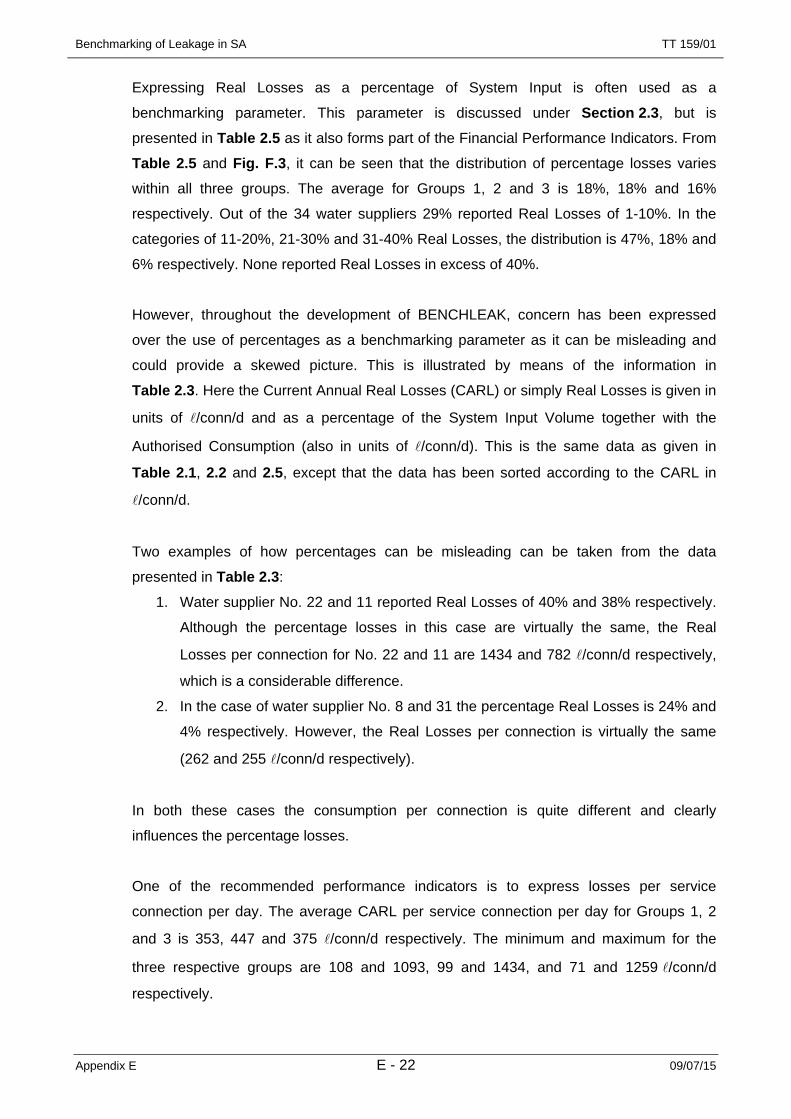
Benchmarking of Leakage in SA
Appendix E E - 22 09/07/15
TT 159/01
Expressing Real Losses as a percentage of System Input is often used as a
benchmarking parameter. This parameter is discussed under Section 2.3, but is
presented in Table 2.5 as it also forms part of the Financial Performance Indicators. From
Table 2.5 and Fig. F.3, it can be seen that the distribution of percentage losses varies
within all three groups. The average for Groups 1, 2 and 3 is 18%, 18% and 16%
respectively. Out of the 34 water suppliers 29% reported Real Losses of 1-10%. In the
categories of 11-20%, 21-30% and 31-40% Real Losses, the distribution is 47%, 18% and
6% respectively. None reported Real Losses in excess of 40%.
However, throughout the development of BENCHLEAK, concern has been expressed
over the use of percentages as a benchmarking parameter as it can be misleading and
could provide a skewed picture. This is illustrated by means of the information in
Table 2.3. Here the Current Annual Real Losses (CARL) or simply Real Losses is given in
units of l/conn/d and as a percentage of the System Input Volume together with the
Authorised Consumption (also in units of l/conn/d). This is the same data as given in
Table 2.1, 2.2 and 2.5, except that the data has been sorted according to the CARL in
l/conn/d.
Two examples of how percentages can be misleading can be taken from the data
presented in Table 2.3:
1. Water supplier No. 22 and 11 reported Real Losses of 40% and 38% respectively.
Although the percentage losses in this case are virtually the same, the Real
Losses per connection for No. 22 and 11 are 1434 and 782 l/conn/d respectively,
which is a considerable difference.
2. In the case of water supplier No. 8 and 31 the percentage Real Losses is 24% and
4% respectively. However, the Real Losses per connection is virtually the same
(262 and 255 l/conn/d respectively).
In both these cases the consumption per connection is quite different and clearly
influences the percentage losses.
One of the recommended performance indicators is to express losses per service
connection per day. The average CARL per service connection per day for Groups 1, 2
and 3 is 353, 447 and 375 l/conn/d respectively. The minimum and maximum for the
three respective groups are 108 and 1093, 99 and 1434, and 71 and 1259 l/conn/d
respectively.

Benchmarking of Leakage in SA
Appendix E E - 23 09/07/15
TT 159/01
From these figures it is evident that expressing Real Losses per connection shows no
definite trends with regard to grouping, which proves that it is not biased in terms of
system size, system input, unit consumption, etc. As in the case of CARL per connection/
day, expressing Real Losses per kilometre of mains or per connection per meter of
pressure also shows no definite trends or distribution patterns. This is proof of the
successfulness of the BENCHLEAK Model as a benchmarking tool.
Table 2.3: Illustrating the problem with percentages
Ref No. Current Annual Real Losses
Current Annual Real Losses
Authorised Consumption
(l/conn/d ) (% of System Input) (l/conn/d) 22 1 434 40.3 1 765
34 1 259 12.7 8 329 7 1 093 26.0 2 841
21 865 25.8 2 270 11 782 38.2 1 070 27 731 27.1 1 783 19 498 18.5 2 070 30 467 18.3 1 964 32 457 16.6 2 176 15 456 22.4 1 468 5 434 22.3 1 406 1 325 13.2 2 067
18 323 16.7 1 531 24 314 7.1 4 036 10 303 18.4 1 264 17 286 12.5 1 932 29 262 16.4 1 275 8 262 23.9 767
31 255 4.2 4 566 28 230 12.7 1 525 2 230 18.9 927
16 214 16.3 1 037 26 208 10.0 1 821 3 196 13.2 1 250
14 181 9.6 1 667 12 174 14.9 952 23 169 15.7 864 4 168 9.8 1 502 9 164 14.1 965
13 111 9.7 1 009 6 108 7.6 1 295
20 99 6.0 1 438 25 76 3.9 1 837 33 71 9.2 684

Benchmarking of Leakage in SA
Appendix E E - 24 09/07/15
TT 159/01
2.3.2. Current Annual Real Losses as Percentage of System Input Volume The use of Current Annual Real Losses expressed as a percentage of System Input
Volume as an indicator of leakage can often be misleading. This is due to the fact that the
percentage leakage is heavily dependent upon the total consumption, which, in turn,
varies significantly from one system to another. The same leakage can result in
significantly different percentage losses, and for this reason percentage losses are not
recommended as a comparative performance indicator.
In South Africa, this is particularly important due to the extreme conditions encountered in
various parts of the country. In many parts of the country there are areas of great
affluence where the water consumption per capita is very high. Adjoining these affluent
areas are areas of extreme poverty where the per capita consumption is very low and
often closer to 25 l /head/day. If the two systems have similar levels of real leakage, the
water supplier to the affluent area will be able to show a percentage leakage of less than
10% while the supplier to the low-income area may struggle to achieve leakage levels of
below 20%. In reality, however, the supplier to the low-income area may be more efficient
in reducing leakage than its counterpart in the affluent area, although this is not indicated
by the percentage losses.
From Fig. F.3 it can be seen the “Current Annual Real Losses” as percentage of System
Input Volume range from about 4% to about 40% for the reference data set with an
average value of 16%.
2.3.3. Current Annual Real Losses per Kilometre of Mains The length of mains in a system provides an indication of the size of the system. “Length
of mains” is defined as the total length of supply and distribution mains in the system.
“Current Annual Real Losses by Volume” is the total “System Input Volume” minus the
“Authorised Consumption” and the “Apparent Losses” (Refer to the BENCHLEAK User
Guide for more detail).
This parameter is also closely linked to the size of the system and will depend largely on
the “System Input Volume”, the basis of estimating “Apparent Losses” and the distribution
of the “Authorised Consumption”.
The parameter provides an indication of the real water losses that are occurring in the
system and the accuracy of this value depends on the reliability of the estimates of
“System Input” and “Authorised Consumption”. An individual water supplier can rate the
performance of his own system on an annual basis by using the “Annual Real Losses by

Benchmarking of Leakage in SA
Appendix E E - 25 09/07/15
TT 159/01
Volume”. This parameter, however, can’t be used to benchmark performance against
other systems, since “System Input Volume”, “Authorised Consumption” and “Apparent
Losses by Volume” are different for each system.
The distribution of “Current Annual Real Losses by Volume” for the reference set ranges
from approximately 25 M l/yr to approximately 37 500 M l/yr. Expressing “Current Annual
Real Losses” as losses per kilometre of mains per day provides a more meaningful
performance indicator and allows a direct comparison between different systems.
From Fig. F.4, it can be seen the “Current Annual Real Losses per Kilometre of Mains”
ranges from approximately 2 000 l/km of mains/d to approximately
50 000 l/ km of mains/ day with an average value in the order of 17 000 l/ km of mains/
day.
2.3.4. Current Annual Real Losses per Connection As discussed in the previous section for the “Current Annual Real Losses per Kilometre of
Mains”, expressing the “Current Annual Real Losses” as losses per connection per day
also helps to remove the influence of the size of the system, and allows a more direct
comparison between different systems.
From Fig. F.5 it can be seen the “Current Annual Real Losses per Connection” range from
approximately 70 l/conn/d to approximately 1 400 l/conn/d with an average value in the
order of 400 l/conn/d.
2.3.5. Current Annual Real Losses per Connection per metre of Pressure Different systems operate under different average operating pressures, as can be seen in
Section 2.2.2. It is also known that leakage is influenced directly by pressure and in order
to remove this influence the previous indicators of Real Losses can be divided by the
average operating pressure.
Fig. F.6 shows the “Current Annual Real Losses per Connection per Metre of Pressure”
and it can be seen that the values range from approximately 1.0 l/conn/d /m pressure to
almost 30 l/conn/d/m pressure with an average value of approximately 10 l/conn/d/m
pressure.

Benchmarking of Leakage in SA
Appendix E E - 26 09/07/15
TT 159/01
2.4. SELECTED FINANCIAL PERFORMANCE INDICATORS
2.4.1. Summary of Results Table 2.5 provides a summary of the financial performance indicators for the sample
group. Real Losses as a percentage of the System Input Volume is discussed under
Section 2.3. The total Non-Revenue water as percentage of System Input Volume ranges
from about 6% to about 52%. Again, no definite trends can be picked up between the
different groupings and the distribution seems to be irregular. The average percentage for
the groups is almost uniform with 26%, 23% and 21% for Groups 1, 2 and 3 respectively.
Little confidence is attached to the data with regard to Non-Revenue water as a
percentage of Running Cost. The reason for this is simply because it was evident that
Water Suppliers found it difficult to provide a reasonably accurate break-up between the
components of Non-Revenue water, which are:
• Unbilled Authorised Consumption,
• Apparent Losses, and
• Real Losses.
It is even more difficult for Water Suppliers to provide a break-up of the components of the
Unbilled Authorised portion of Non-Revenue water. 9% of Water Suppliers could not
provide an estimate of the average annual operating cost of the system. To this end, the
distribution of Non-Revenue Water as a percentage of Running Cost is as given in
Table 2.4.
Table 2.4: Distribution of Non-Revenue Water as % of Running Cost
Non-Revenue Water as % of Running Cost % of Water Suppliers in this category
No data 9
1 – 10 % 15
11 – 20 % 31
21 – 30 % 15
31 – 40 % 15
41 – 50 % 6
51 – 60 % 0
61 – 70 % 3
71 – 80 % 3
81 – 90% 3
91 – 100% 0

Benchmarking of Leakage in SA
Appendix E E - 27 09/07/15
TT 159/01
Table 2.5: Selected Financial Performance Indicators
Utility Ref No.
Non-Revenue Water components as % of System Input Volume
Total Non-revenue
water as % of
Non-Revenue Water components as % of Cost of Running System
Total Non-Revenue
Water as % of
Unbilled Consumption
Apparent Losses
Real Losses
System Input Volume
Unbilled Consumption
Apparent Losses
Real Losses
Annual Running Cost
Group 1 – Large (No of service connections > 50 000) 1 18 3 13 34 19 4 8 312 0 5 19 24 03 0 3 13 16 0 3 10 134 5 2 10 17 5 2 5 125 0 6 22 28 2 27 56 866 10 2 8 20 19 4 8 317 0 6 26 33 1 8 15 248 0 6 24 30 0 9 17 269 0 4 14 18 0 6 10 16
10 2 5 18 25 2 6 11 1911 4 10 38 52 10 21 38 6912 0 3 15 18 0 5 11 16
Group Ave 3 5 18 26 5 9 17 28Group 2 – Medium (10 000 < No of service connections < 50 000)
13 0 2 10 12 0 4 7 1114 0 2 10 12 0 3 7 1015 0 6 22 28 0 8 22 3016 0 4 16 21 017 0 3 13 16 018 0 4 17 21 0 7 12 1919 6 5 18 29 10 8 17 3520 0 2 6 8 0 3 14 1821 2 6 26 35 5 14 24 4222 0 10 40 50 0 31 41 72
Group Ave 1 4 18 23 2 10 18 24Group 3 – Small (No of service connections < 10 000)
23 0 4 16 20 0 6 12 1824 0 2 7 9 0 1 5 625 9 1 4 14 23 2 3 2826 18 3 10 30 14 2 9 2527 0 7 27 34 0 14 18 3228 24 3 13 40 35 5 7 4629 0 4 16 20 0 5 7 1130 7 5 18 30 10 7 18 3531 0 1 4 6 1 4 3 832 0 4 17 21 0 0 1 133 0 2 9 11 0 2 9 1134 0 3 13 16 0 0 1 1
Group Ave 5 3 12 21 7 4 8 19Sample Ave 3 4 16 23 5 7 14 24

Benchmarking of Leakage in SA
Appendix E E - 28 09/07/15
TT 159/01
2.4.2. Real Losses as a Percentage of Running Cost “Real Losses” are generally valued in terms of the purchase price of the water by the
water supplier or the cost of producing the water in the case of suppliers who abstract and
purify their own water rather than purchasing from a bulk supplier. In order to express the
“Real Losses” in financial terms they are often given as a percentage of the total running
cost of the system. Expressing the losses in such terms often serves as an incentive for
water suppliers to play a more active role in leakage management. The “Real Losses as a
percentage of Running Cost” are shown in Fig. F.7 and range from approximately 1% to
55% with an average value in the order of 15%.
2.4.3. Non-Revenue Water as a Percentage of System Input Volume Non-Revenue water comprises the following components:
• Unbilled Authorised Consumption,
• Apparent Losses,
• Real Losses.
Apparent losses represent direct loss of income to the water supplier and are therefore
usually expressed in terms of the selling price of the water and not the purchase price, as
was the case for the “Real Losses”. The “Unbilled Authorised Consumption” would also
normally be expressed in terms of the selling price of water by the supplier. It is
sometimes useful to express the total “Non-Revenue Water” as a percentage of the total
volume of water going into the system in order to gauge the performance of the system
from year to year. “Non-Revenue Water as Percentage of System Input Volume” is shown
in Fig. F.8 and range from approximately 6% to more than 50% with an average value of
almost 25%.
2.4.4. Non-Revenue Water as a Percentage of Running Cost A more meaningful performance indicator for the non-revenue water is to express it as a
percentage of the annual system operating cost. The results form the sample data sets
are shown in Fig. F.9, and as can be seen, the values range from approximately 1% to
more than 80% with an average value of almost 25%.
2.5. KEY PERFORMANCE INDICATORS
2.5.1. Summary of Results Table 2.6 provides a summary of the key performance indicators for the sample group,
which is the Unavoidable Annual Real Losses (UARL) and the Infrastructure Leakage
Index (ILI). These two parameters are the ultimate measure of the BENCHLEAK Model as

Benchmarking of Leakage in SA
Appendix E E - 29 09/07/15
TT 159/01
an unbiased tool that successfully removes various influential factors when benchmarking
the performance of one system against that of another.
Table 2.6: Key Performance Indicators
Utility Ref No.
Unavoidable Real Losses Infrastructure Leakage Index
(Ml/yr) (l/conn/d)
Group 1 – Large (No of service connections > 50 000) 1 6 086 53 6.2 2 4 510 44 5.2 3 2 722 46 4.2 4 3 322 57 3.0 5 3 202 83 5.2 6 1 576 41 2.6 7 3 526 121 9.1 8 1 237 48 5.4 9 1 452 58 2.9
10 1 752 70 4.3 11 1 682 77 10.2 12 1 083 51 3.4
Group Ave 2 679 62 5.1Group 2 – Medium (10 000 < No of service connections < 50 000)
13 860 50 2.2 14 604 39 4.6 15 499 38 11.8 16 722 58 3.7 17 776 66 4.3 18 829 73 4.4 19 349 53 9.4 20 305 51 1.9 21 190 49 17.5 22 275 73 19.8
Group Ave 541 55 8.0Group 3 – Small (No of service connections < 10 000)
23 203 58 2.9 24 165 49 6.4 25 119 37 2.0 26 120 56 3.7 27 113 73 10.0 28 124 85 2.7 29 39 40 6.5 30 33 50 9.4 31 28 58 4.4 32 21 40 11.3 33 26 73 1.0 34 7 74 17.0
Group Ave 83 58 6.4Sample Ave 1 134 59 6.4

Benchmarking of Leakage in SA
Appendix E E - 30 09/07/15
TT 159/01
No definite trends are evident with regard to the distribution of the UARL or the ILI for the
three groups. The average value for the UARL for Groups 1, 2 and 3 are 62, 55 and
58 l/conn/d respectively. For the ILI it is 5.1, 8.0 and 6.4 for Groups 1, 2 and 3
respectively.
The distribution of the UARL and ILI for the total sample group is given in Table 2.7.
Table 2.7: Distribution of UARL and ILI
UARL Category (l/conn/d)
% in this category ILI Category
% in this category
31 – 40 15 1 – 5 62
41 – 50 24 6 – 10 23
51 – 60 28 11 – 15 6
61 – 70 6 16 – 20 9
71 – 80 18 > 20 0
81 – 90 6
91 – 100 0
> 101 3
2.5.2. Unavoidable Annual Real Losses per Connection It is impossible, even in well-managed systems, to eliminate leakage completely. It is clear
that there is some minimum level of leakage that can be considered as the “Unavoidable
Annual Real Losses” for any given system. The method for calculating the unavoidable
leakage is provided in the BENCHLEAK User Guide and is not repeated in the current
document. The volume of unavoidable leakage for any system is directly related to the
size of the system (length of mains and number of service connections) together with the
average operating pressure.
The “Unavoidable Annual Real Losses” by volume is on its own a meaningless parameter,
unless it is divided by the length of mains or number of service connections. The
“Unavoidable Annual Real Losses per Connection” is the preferred performance indicator.
The “Unavoidable Annual Real Losses” per connection for the reference data set are
shown in Fig. F.10 and vary from approximately 40 l/conn/d to almost 120 l/conn/d with
an average value in the order of 60 l/conn/d.
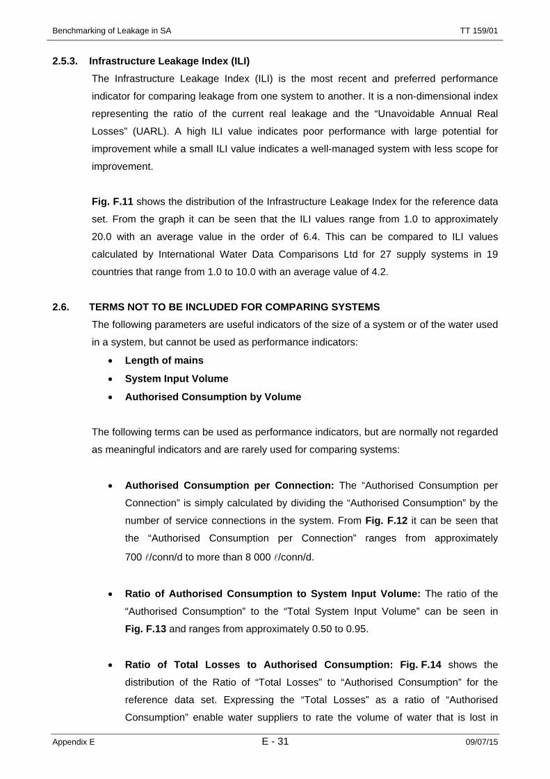
Benchmarking of Leakage in SA
Appendix E E - 31 09/07/15
TT 159/01
2.5.3. Infrastructure Leakage Index (ILI) The Infrastructure Leakage Index (ILI) is the most recent and preferred performance
indicator for comparing leakage from one system to another. It is a non-dimensional index
representing the ratio of the current real leakage and the “Unavoidable Annual Real
Losses” (UARL). A high ILI value indicates poor performance with large potential for
improvement while a small ILI value indicates a well-managed system with less scope for
improvement.
Fig. F.11 shows the distribution of the Infrastructure Leakage Index for the reference data
set. From the graph it can be seen that the ILI values range from 1.0 to approximately
20.0 with an average value in the order of 6.4. This can be compared to ILI values
calculated by International Water Data Comparisons Ltd for 27 supply systems in 19
countries that range from 1.0 to 10.0 with an average value of 4.2.
2.6. TERMS NOT TO BE INCLUDED FOR COMPARING SYSTEMS The following parameters are useful indicators of the size of a system or of the water used
in a system, but cannot be used as performance indicators:
• Length of mains
• System Input Volume
• Authorised Consumption by Volume
The following terms can be used as performance indicators, but are normally not regarded
as meaningful indicators and are rarely used for comparing systems:
• Authorised Consumption per Connection: The “Authorised Consumption per
Connection” is simply calculated by dividing the “Authorised Consumption” by the
number of service connections in the system. From Fig. F.12 it can be seen that
the “Authorised Consumption per Connection” ranges from approximately
700 l/conn/d to more than 8 000 l/conn/d.
• Ratio of Authorised Consumption to System Input Volume: The ratio of the
“Authorised Consumption” to the “Total System Input Volume” can be seen in
Fig. F.13 and ranges from approximately 0.50 to 0.95.
• Ratio of Total Losses to Authorised Consumption: Fig. F.14 shows the
distribution of the Ratio of “Total Losses” to “Authorised Consumption” for the
reference data set. Expressing the “Total Losses” as a ratio of “Authorised
Consumption” enable water suppliers to rate the volume of water that is lost in

Benchmarking of Leakage in SA
Appendix E E - 32 09/07/15
TT 159/01
terms of the volume of water that is consumed. Although this is not one of the
preferred performance indicators, it can be of interest to water suppliers. For the
reference data set, the highest ratio was found to be 1.02, indicating that the “Total
Losses” were slightly more than the “Authorised Consumption” (clearly a situation
of concern). The smallest ratio of 0.05 indicates that the “Total Losses” are only
5% of the “Authorised Consumption by Volume”.

Benchmarking of Leakage in SA
Appendix E E - 33 09/07/15
TT 159/01
3. CONCLUSIONS AND RECOMMENDATIONS 3.1. CONCLUSIONS
From the information gathered during the leakage-benchmarking case study, several
conclusions can be drawn:
• The South African water supply industry is generally lagging best international
practices with respect to leakage management in potable water distribution
systems. It was only during 1996 that the Water Research Commission (WRC)
identified the need to control the level of unaccounted-for water in South Africa
with the result that the development of a standard methodology or terminology for
the calculation of water losses was only initiated in the late 1990’s.
• The information required to calculate the various performance indicators used in
this case study is often not available from the water suppliers, despite the fact that
the information is very basic. For example, many water suppliers have difficulties
in providing information such as the total length of mains and number of service
connections in their system.
• While the benchmarking procedure was initially developed for complete water
distribution systems, the same approach can easily be used for individual
management zones within a single supply system. In this manner this approach
can be used to identify problem management zones within a system as well as to
compare one system with another.
• Water supply systems in South Africa are poorly metered with regard to both bulk
and consumer metering.
• The ILI values for the sample group range from 1.0 to approximately 28.0 with an
average value in the order of 7.0. The average values are 5.1, 8.0 and 6.4 for
Groups 1, 2 and 3 respectively. This can be compared to ILI values calculated by
International Water Data Comparisons Ltd for 27 supply systems in 19 countries
that range from 1.0 to 10.0 with an average value of 4.2.
• For South African conditions it would be unusual to achieve an ILI value of below
2.0 and values in the order of 5.0 are common and represent systems in a
reasonable condition. For smaller systems one would expect that since these
systems are smaller and easier to manage, it should be possible to achieve an ILI
of 3.0 through improved management practices. This suggests that there is
considerable scope for improvement in Groups 2 and 3, while Group 1 could
probably achieve an ILI of about 4.0.

Benchmarking of Leakage in SA
Appendix E E - 34 09/07/15
TT 159/01
3.2. RECOMMENDATIONS Based on the conclusions from this report, it is recommended that:
• The importance of leakage management should gain greater exposure and
emphasis from water services institutions such as the Water Research
Commission and the Department of Water Affairs and Forestry.
• Water services authorities and providers should be made aware of the existence of
the leakage-benchmarking methodology in order to create an environment of
cooperation when water services institutions embark on further case studies.
• The performance indicators used to benchmark different water suppliers should be
chosen carefully in order to make benchmarking across different categories of
service providers or demarcation areas meaningful.
• Users of the benchmarking model should familiarise themselves fully with the
content of the BENCHLEAK User Guide, before embarking on applying the model.
• The benchmarking model should be compiled into a full database for the South
African water supply industry to facilitate collection and collation of data for an
ongoing annual national benchmarking exercise. The results can then be
presented in a standard format and sent to all water suppliers who will participate
in the exercise. Obviously some of the figures quoted in this case study are based
on a number of broad assumptions and the true situation can only be established if
all of the approximately 300 service providers complete the BENCHLEAK form.
The figures do, however, indicate the possible magnitude of Real Losses
throughout the country.

Benchmarking of Leakage in SA
Appendix F 09/07/15
TT 159/01
APPENDIX F
Results for Participating Water Suppliers

Benchmarking of Leakage in SA
Appendix F F - 2 09/07/15
TT 159/01
Benchmarking of Real Water Leakage in South Africa Results and Analysis of Local Authorities Data Using
BENCHLEAKAverage operating pressure Fig. F.1
0
20
40
60
80
1 2 3 4 5 6 7 8 9 10 11 12 13 14 15 16 17 18 19 20 21 22 23 24 25 26 27 28 29 30 31 32 33 34
Reference Number
Met
re
Average = 47
0
20
40
60
80
1 2 3 4 5 6 7 8 9 10 11 12 13 14 15 16 17 18 19 20 21 22 23 24 25 26 27 28 29 30 31 32 33 34
Reference Number
Met
re
Average = 47

Benchmarking of Leakage in SA
Appendix F F - 3 09/07/15
TT 159/01
Benchmarking of Real Water Leakage in South Africa Results and Analysis of Local Authorities Data Using
BENCHLEAKDensity of connections Fig. F.2
0
50
100
150
1 2 3 4 5 6 7 8 9 10 11 12 13 14 15 16 17 18 19 20 21 22 23 24 25 26 27 28 29 30 31 32 33 34
Reference Number
Con
nect
ions
/ kilo
met
er o
f mai
n
Average = 49
0
50
100
150
1 2 3 4 5 6 7 8 9 10 11 12 13 14 15 16 17 18 19 20 21 22 23 24 25 26 27 28 29 30 31 32 33 34
Reference Number
Con
nect
ions
/ kilo
met
er o
f mai
n
Average = 49

Benchmarking of Leakage in SA
Appendix F F - 4 09/07/15
TT 159/01
Benchmarking of Real Water Leakage in South Africa Results and Analysis of Local Authorities Data Using
BENCHLEAK
Current Annual Real Losses as a percentage of the System
Inout VolumeFig. F.3
0
10
20
30
40
50
1 2 3 4 5 6 7 8 9 10 11 12 13 14 15 16 17 18 19 20 21 22 23 24 25 26 27 28 29 30 31 32 33 34
Reference Number
Perc
ent
Average = 16
0
10
20
30
40
50
1 2 3 4 5 6 7 8 9 10 11 12 13 14 15 16 17 18 19 20 21 22 23 24 25 26 27 28 29 30 31 32 33 34
Reference Number
Perc
ent
Average = 16

Benchmarking of Leakage in SA
Appendix F F - 5 09/07/15
TT 159/01
Benchmarking of Real Water Leakage in South Africa Results and Analysis of Local Authorities Data Using
BENCHLEAKCurrent Annual Real Losses per
km of mains per day Fig. F.4
0
10
20
30
40
50
60
1 2 3 4 5 6 7 8 9 10 11 12 13 14 15 16 17 18 19 20 21 22 23 24 25 26 27 28 29 30 31 32 33 34
Thousands
Reference Number
Litr
es/k
m o
f mai
n/da
yAverage = 16 600
0
10
20
30
40
50
60
1 2 3 4 5 6 7 8 9 10 11 12 13 14 15 16 17 18 19 20 21 22 23 24 25 26 27 28 29 30 31 32 33 34
Thousands
Reference Number
Litr
es/k
m o
f mai
n/da
yAverage = 16 600

Benchmarking of Leakage in SA
Appendix F F - 6 09/07/15
TT 159/01
Benchmarking of Real Water Leakage in South Africa Results and Analysis of Local Authorities Data Using
BENCHLEAKCurrent Annual Real Losses in litres per connection per day Fig. F.5
0
200
400
600
800
1000
1200
1400
1600
1 2 3 4 5 6 7 8 9 10 11 12 13 14 15 16 17 18 19 20 21 22 23 24 25 26 27 28 29 30 31 32 33 34
Reference Number
Litr
es/c
onn/
day
Average = 388
0
200
400
600
800
1000
1200
1400
1600
1 2 3 4 5 6 7 8 9 10 11 12 13 14 15 16 17 18 19 20 21 22 23 24 25 26 27 28 29 30 31 32 33 34
Reference Number
Litr
es/c
onn/
day
Average = 388
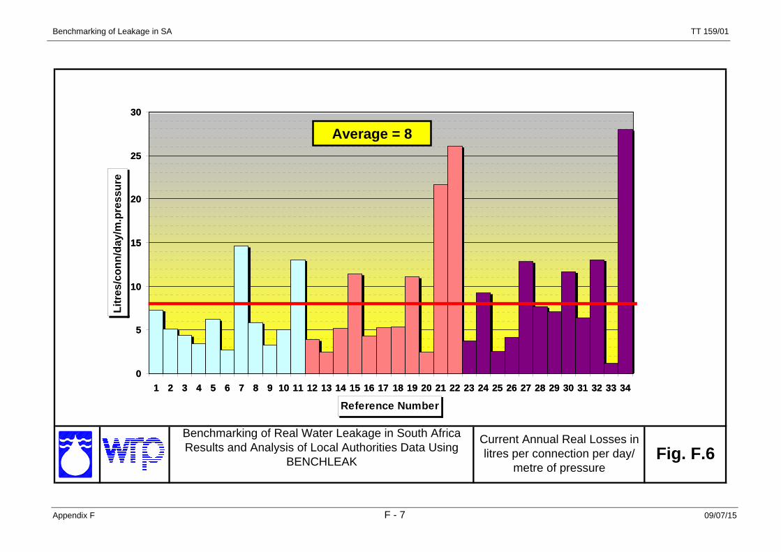
Benchmarking of Leakage in SA
Appendix F F - 7 09/07/15
TT 159/01
Benchmarking of Real Water Leakage in South Africa Results and Analysis of Local Authorities Data Using
BENCHLEAK
Current Annual Real Losses in litres per connection per day/
metre of pressureFig. F.6
0
5
10
15
20
25
30
1 2 3 4 5 6 7 8 9 10 11 12 13 14 15 16 17 18 19 20 21 22 23 24 25 26 27 28 29 30 31 32 33 34
Reference Number
Litr
es/c
onn/
day/
m.p
ress
ure
Average = 8
0
5
10
15
20
25
30
1 2 3 4 5 6 7 8 9 10 11 12 13 14 15 16 17 18 19 20 21 22 23 24 25 26 27 28 29 30 31 32 33 34
Reference Number
Litr
es/c
onn/
day/
m.p
ress
ure
Average = 8

Benchmarking of Leakage in SA
Appendix F F - 8 09/07/15
TT 159/01
Benchmarking of Real Water Leakage in South Africa Results and Analysis of Local Authorities Data Using
BENCHLEAKReal Losses as a percentage of
the annual Running Cost Fig. F.7
0
20
40
60
1 2 3 4 5 6 7 8 9 10 11 12 13 14 15 16 17 18 19 20 21 22 23 24 25 26 27 28 29 30 31 32 33 34
Reference Number
Perc
ent
Average = 14
0
20
40
60
1 2 3 4 5 6 7 8 9 10 11 12 13 14 15 16 17 18 19 20 21 22 23 24 25 26 27 28 29 30 31 32 33 34
Reference Number
Perc
ent
Average = 14
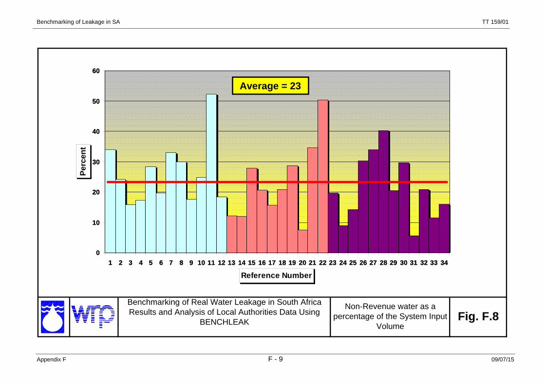
Benchmarking of Leakage in SA
Appendix F F - 9 09/07/15
TT 159/01
Benchmarking of Real Water Leakage in South Africa Results and Analysis of Local Authorities Data Using
BENCHLEAK
Non-Revenue water as a percentage of the System Input
VolumeFig. F.8
0
10
20
30
40
50
60
1 2 3 4 5 6 7 8 9 10 11 12 13 14 15 16 17 18 19 20 21 22 23 24 25 26 27 28 29 30 31 32 33 34
Reference Number
Perc
entAverage = 23
0
10
20
30
40
50
60
1 2 3 4 5 6 7 8 9 10 11 12 13 14 15 16 17 18 19 20 21 22 23 24 25 26 27 28 29 30 31 32 33 34
Reference Number
Perc
entAverage = 23

Benchmarking of Leakage in SA
Appendix F F - 10 09/07/15
TT 159/01
Benchmarking of Real Water Leakage in South Africa Results and Analysis of Local Authorities Data Using
BENCHLEAK
Non-Revenue water as a percentage of the annual
Running CostFig. F.9
0
20
40
60
80
100
1 2 3 4 5 6 7 8 9 10 11 12 13 14 15 16 17 18 19 20 21 22 23 24 25 26 27 28 29 30 31 32 33 34
Reference Number
Perc
ent
Average = 24
0
20
40
60
80
100
1 2 3 4 5 6 7 8 9 10 11 12 13 14 15 16 17 18 19 20 21 22 23 24 25 26 27 28 29 30 31 32 33 34
Reference Number
Perc
ent
Average = 24
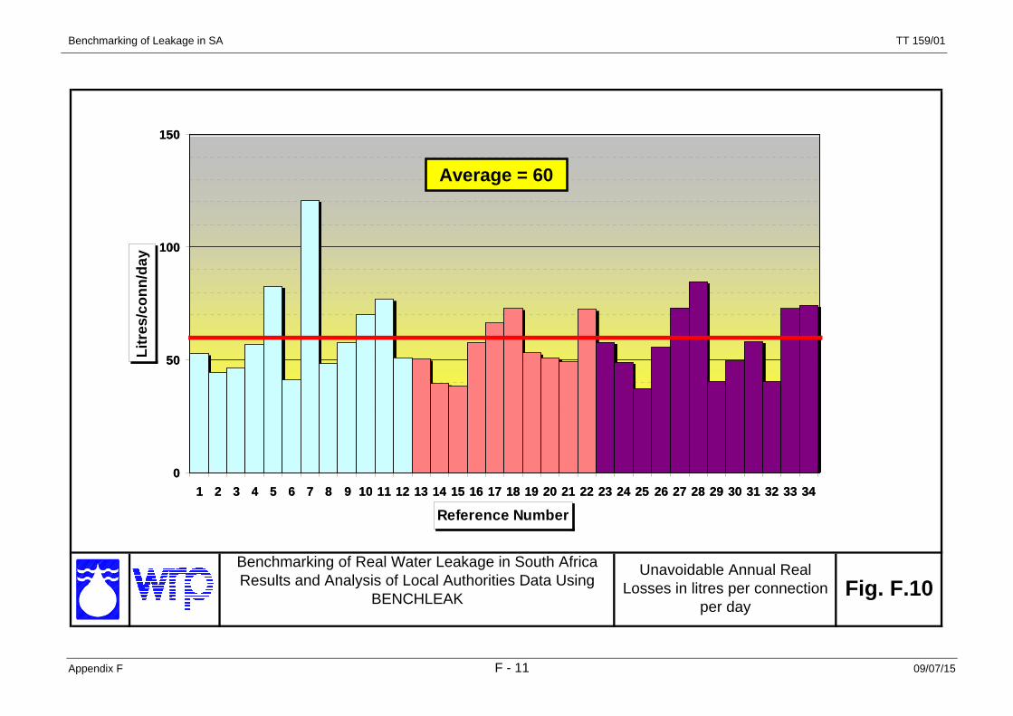
Benchmarking of Leakage in SA
Appendix F F - 11 09/07/15
TT 159/01
Benchmarking of Real Water Leakage in South Africa Results and Analysis of Local Authorities Data Using
BENCHLEAK
Unavoidable Annual Real Losses in litres per connection
per dayFig. F.10
0
50
100
150
1 2 3 4 5 6 7 8 9 10 11 12 13 14 15 16 17 18 19 20 21 22 23 24 25 26 27 28 29 30 31 32 33 34
Reference Number
Litr
es/c
onn/
day
Average = 60
0
50
100
150
1 2 3 4 5 6 7 8 9 10 11 12 13 14 15 16 17 18 19 20 21 22 23 24 25 26 27 28 29 30 31 32 33 34
Reference Number
Litr
es/c
onn/
day
Average = 60

Benchmarking of Leakage in SA
Appendix F F - 12 09/07/15
TT 159/01
Benchmarking of Real Water Leakage in South Africa Results and Analysis of Local Authorities Data Using
BENCHLEAKInfrastructure Leakage Index Fig. F.11
0
10
20
30
1 2 3 4 5 6 7 8 9 10 11 12 13 14 15 16 17 18 19 20 21 22 23 24 25 26 27 28 29 30 31 32 33 34
Reference Number
Infr
astr
actu
re le
akag
e in
dex
Average = 6
0
10
20
30
1 2 3 4 5 6 7 8 9 10 11 12 13 14 15 16 17 18 19 20 21 22 23 24 25 26 27 28 29 30 31 32 33 34
Reference Number
Infr
astr
actu
re le
akag
e in
dex
Average = 6

Benchmarking of Leakage in SA
Appendix F F - 13 09/07/15
TT 159/01
Benchmarking of Real Water Leakage in South Africa Results and Analysis of Local Authorities Data Using
BENCHLEAKAuthorised Consumption in
litres per connection per day Fig. F.12
0
1
2
3
4
5
6
7
8
9
1 2 3 4 5 6 7 8 9 10 11 12 13 14 15 16 17 18 19 20 21 22 23 24 25 26 27 28 29 30 31 32 33 34
Thousands
Reference Number
Litr
es/c
onn/
day
Average = 1900
0
1
2
3
4
5
6
7
8
9
1 2 3 4 5 6 7 8 9 10 11 12 13 14 15 16 17 18 19 20 21 22 23 24 25 26 27 28 29 30 31 32 33 34
Thousands
Reference Number
Litr
es/c
onn/
day
Average = 1900

Benchmarking of Leakage in SA
Appendix F F - 14 09/07/15
TT 159/01
Benchmarking of Real Water Leakage in South Africa Results and Analysis of Local Authorities Data Using
BENCHLEAK
Ratio of Authorised Consumption to System Input
VolumeFig. F.13
0.00
0.20
0.40
0.60
0.80
1.00
1.20
1.40
1.60
1.80
2.00
1 2 3 4 5 6 7 8 9 10 11 12 13 14 15 16 17 18 19 20 21 22 23 24 25 26 27 28 29 30 31 32 33 34
Reference Number
Rat
io
Average = 0.80
0.00
0.20
0.40
0.60
0.80
1.00
1.20
1.40
1.60
1.80
2.00
1 2 3 4 5 6 7 8 9 10 11 12 13 14 15 16 17 18 19 20 21 22 23 24 25 26 27 28 29 30 31 32 33 34
Reference Number
Rat
io
Average = 0.80

Benchmarking of Leakage in SA
Appendix F F - 15 09/07/15
TT 159/01
Benchmarking of Real Water Leakage in South Africa Results and Analysis of Local Authorities Data Using
BENCHLEAKRatio of Total Losses to Authorised Consumption Fig. F.14
0.00
0.20
0.40
0.60
0.80
1.00
1.20
1 2 3 4 5 6 7 8 9 10 11 12 13 14 15 16 17 18 19 20 21 22 23 24 25 26 27 28 29 30 31 32 33 34
Reference Number
Rat
ioAverage = 0.30
0.00
0.20
0.40
0.60
0.80
1.00
1.20
1 2 3 4 5 6 7 8 9 10 11 12 13 14 15 16 17 18 19 20 21 22 23 24 25 26 27 28 29 30 31 32 33 34
Reference Number
Rat
ioAverage = 0.30