development of a vera capability for cilc screening · •fy18 objective to demonstrate in two...
TRANSCRIPT

Development of a VERA Capability for CILC Screening
Authors
Bob Salko1, Travis Lange1, Aaron Wysocki1, Marc-Oliver Delchini1, Ben Collins1, Emre
Tatlie2, Stuart Slattery1, Will Gurecky3, and Analisa Manera4
1. Oak Ridge National Laboratory
2. Westinghouse Electric Company
3. University of Texas, Austin
4. University of Michigan
CASL Industry Council Meeting
April 10, 2018

2
IntroductionPath to development of a CILC screening tool
• Path forward involves:– Developing a capability in VERA-CS for running full-core, pin-resolved simulations for reasonably
accurate identification of areas at risk for CILC
– Developing a high-fidelity capability for analyzing core sub-regions that have been identified to be at risk and for benchmarking with VERA-CS CILC capability
• VERA-CS capability– Development of approach for capturing grid heat transfer effects on crud growth
– Assessment of effect of mesh resolution on crud deposits
– Implementation of corrosion-modeling capability
• High-fidelity capability tool, Cicada– STAR-CCM+ coupled to MAMBA and clad heat transfer and corrosion
– Extension to rod-bundle geometry, two-phase CFD, and usability improvements
• Improvements to crud predictions– System-level calibration
– Fidelity improvements
– Critical for both CIPS and CILC predictions
3
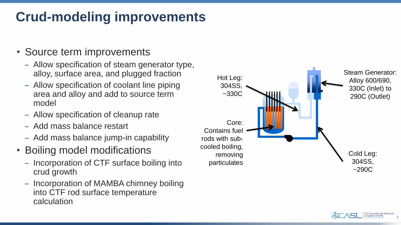
Crud-modeling improvements
• Source term improvements– Allow specification of steam generator type,
alloy, surface area, and plugged fraction
– Allow specification of coolant line piping area and alloy and add to source term model
– Allow specification of cleanup rate
– Add mass balance restart
– Add mass balance jump-in capability
• Boiling model modifications– Incorporation of CTF surface boiling into
crud growth
– Incorporation of MAMBA chimney boiling into CTF rod surface temperature calculation
Cold Leg:
304SS,
~290C
Steam Generator:
Alloy 600/690,
330C (Inlet) to
290C (Outlet)
Core:
Contains fuel
rods with sub-
cooled boiling,
removing
particulates
Hot Leg:
304SS,
~330C

4
High-fidelity CILC modeling with Cicada
• Cicada provides coupled crud, oxidation, and thermal models of cladding
• General interface being developed for core-scale analysis within VERA-CS with coupling to CTF
• Demonstrated multiple state point coupling with STAR-CCM+ for high-fidelity, rod/assembly-level analysis at CFD resolution– Collaboration in progress with both Siemens (STAR-
CCM+ developer) and Westinghouse on development and use of this feature
• Crud model incorporates latest CASL work on MAMBA
• FY18 objective to demonstrate in two separate use cases:– Cicada on 5x5 CFD problem with two-phase flow
– Within VERA-CS for CILC screening
• Benchmarking against VERA-CS CILC capability
Cicada model diagram. Fluid parameters are provided by subchannel and CFD and heat fluxes provided by VERA-CS are used as boundary conditions on each
Cicada pin.
CicadaSTAR/MAMBA WEC Results
10
Cicada CFD coupling example output. CILC results are obtained on the STAR-CCM+ mesh and can be analyzed directly in STAR-CCM+
5
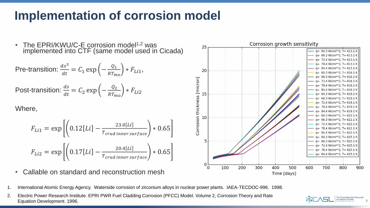
Implementation of corrosion model
• The EPRI/KWU/C-E corrosion model1,2 was implemented into CTF (same model used in Cicada)
Pre-transition: 𝑑𝑠3
𝑑𝑡= 𝐶1 exp −
𝑄1
𝑅𝑇𝑚𝑜∗ 𝐹𝐿𝑖1,
Post-transition: 𝑑𝑠
𝑑𝑡= 𝐶2 exp −
𝑄2
𝑅𝑇𝑚𝑜∗ 𝐹𝐿𝑖2
Where,
𝐹𝐿𝑖1 = exp 0.12 𝐿𝑖 −23.0 𝐿𝑖
𝑇𝑐𝑟𝑢𝑑 𝑖𝑛𝑛𝑒𝑟 𝑠𝑢𝑟𝑓𝑎𝑐𝑒∗ 0.65
𝐹𝐿𝑖2 = exp 0.17 𝐿𝑖 −20.4 𝐿𝑖
𝑇𝑐𝑟𝑢𝑑 𝑖𝑛𝑛𝑒𝑟 𝑠𝑢𝑟𝑓𝑎𝑐𝑒∗ 0.65
• Callable on standard and reconstruction mesh
1. International Atomic Energy Agency. Waterside corrosion of zirconium alloys in nuclear power plants. IAEA-TECDOC-996. 1998.
2. Electric Power Research Institute. EPRI PWR Fuel Cladding Corrosion (PFCC) Model. Volume 2, Corrosion Theory and Rate
Equation Development. 1996.

6
Development of CFD-informed grid heat transfer modelCalibration of global CTF models
• Calibration of turbulent-mixing coefficient to match CTF temperature distributions to STAR-CCM+
• Calculation of grid loss coefficient on per-channel basis from STAR-CCM+ for specific spacer grid design
• Calibration of CTF heat transfer model to STAR-CCM+ results
Calibrated mixing coefficient1
1. R. Smith, et al. “High-to-Low Activities across VVI, AMA, and PHI,” CASL-U-2017-
1447-000, 2017
RMSE for subchannel temperatures
compared to STAR-CCM+ predictions
drops by factor of two after calibration
Improvement of rod surface temperature
prediction compared to STAR-CCM+ after
calibration of Dittus-Boelter model

7
Development of CFD-informed grid heat transfer modelReconstruct CFD rod surface effects in CTF
• Develop heat transfer and turbulent kinetic energy multiplier maps as function of rod surface location and grid geometry
• Add capability in CTF to create a refined coupling mesh for MAMBA coupling
𝑀 𝑧 − 𝑧𝑔, 𝜃 =𝑁𝑢𝑔𝑟𝑖𝑑 𝑧 − 𝑧𝑔, 𝜃
𝑁𝑢𝑏𝑎𝑟𝑒 𝑧 − 𝑧𝑔
• Develop CFD models to generate data for reconstruction
Example of HTC rod surface data map developed
by STAR-CCM+ and read by CTF
8
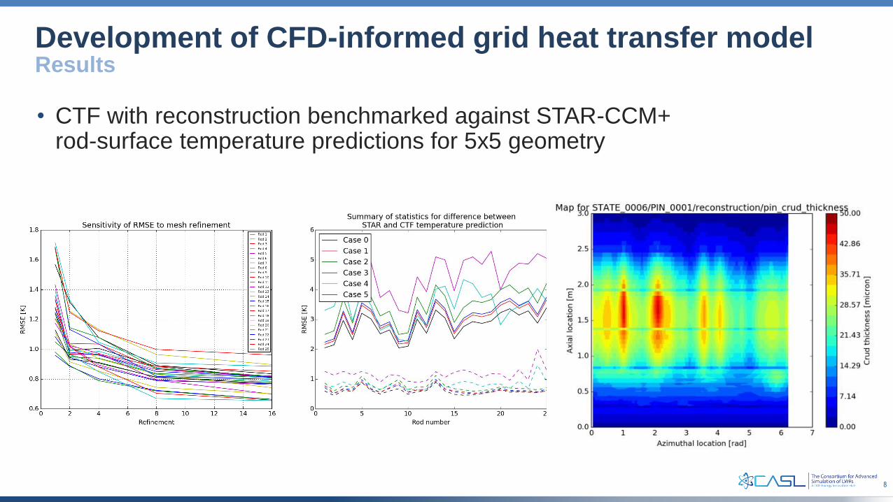
Development of CFD-informed grid heat transfer modelResults
• CTF with reconstruction benchmarked against STAR-CCM+ rod-surface temperature predictions for 5x5 geometry

9
Demonstration for Progression Problem 9
Case Refinement
Maximum Corrosion
Thickness [u]
Minimum Corrosion
Thickness [u] Difference [u]
No Grid N/A 30.89 29.36 1.53
YHL N/A 30.67 29.07 1.60
Hi2lo #1 1x1 28.83 24.53 4.30
Hi2lo #2 2x2 29.02 20.61 8.41
Hi2lo #3 4x4 29.65 19.38 10.27
* data chosen for random pin in model
Maximum Crud Thickness [u]
Maximum Corrosion Thickness [u]
Case No Grid YHL Hi2lo #1 Hi2lo #2 Hi2lo #3
Maximum Pin Crud
Thickness [u]51.03 50.9 42.47 42.57 42.56
Core Crud Mass
[kg]42.97 40.18 33.11 33.13 33.17
*Generic grid HTC/TKE data file used for demonstration

10
Future Work
• Modeling of Seabrook Cycle 5 and assessment of crud and corrosion behavior
• Assessment of effect of coupling mesh refinement
• Benchmarking of VERA-CS and Cicada for 5x5 geometry
• Development of STAR-CCM+ models for Seabrook and Palo-Verde 17x17 spacer grids to generate data for reconstruction
