development of an oil extraction machine for jatropha ... · aim: this study aimed to solve one of...
TRANSCRIPT
_____________________________________________________________________________________________________ *Corresponding author: Email: [email protected];
Journal of Scientific Research & Reports 6(4): 313-328, 2015; Article no.JSRR.2015.157
ISSN: 2320-0227
SCIENCEDOMAIN international www.sciencedomain.org
Development of an Oil Extraction Machine for Jatropha curcas Seeds
A. T. Salawu1*, M. Isiaka1 and M. L. Suleiman1
1Department of Agricultural Engineering, Ahmadu Bello University, Zaria, Nigeria.
Authors’ contributions
This work was carried out in collaboration between all authors. Author ATS designed the study, wrote the protocol, wrote the first draft of the manuscript, and carried out the literature searches. Author MI
coordinated the performance evaluation. Author MLS managed the experimental process. All authors read and approved the final manuscript.
Article Information
DOI: 10.9734/JSRR/2015/15148
Editor(s): (1) Ana Ribeiro-Barros, Biotrop Center - Environment, Agriculture and Development, Tropical Research Institute (IICT),
Oeiras, Portugal. (2) Francesco Montemurro, C.R.A. SSC - Research Unit of the Study of Cropping Systems, Metaponto, Italy.
Reviewers: (1) Anonymous, Ghana. (2) Anonymous, Brazil. (3) Anonymous, India.
(4) Anonymous, Russia. Complete Peer review History: http://www.sciencedomain.org/review-history.php?iid=965&id=22&aid=8441
Received 10th November 2014 Accepted 24th February 2015
Published 13th
March 2015
ABSTRACT
Aim: This study aimed to solve one of the problems which Jatropha curcas seeds (JCS) oil extraction industry is facing in the Northern part of Nigeria; the lack of efficient small scale oil extraction machines. A small scale JCS oil extraction machine was therefore designed, developed, and evaluated for performance. Study Design: The study was conducted using 3 × 3 × 3 Factorial Experimental Design. The results obtained were analysed using ANOVA while Least Significant Difference (LSD) test was used to separate the means. Place and Duration of Study: Department of Agricultural Engineering, Ahmadu Bello University, Zaria, Nigeria between January 2011 and April 2013. Methodology: Base on design calculations, locally sourced materials with indigenous technology were used for the development of the machine. In evaluating the developed prototype machine, the effect of speed, feed-rate, and moisture content on throughput, extraction rate, and extraction efficiency were determined.
Original Research Article
Salawu et al.; JSRR, 6(4): 313-328, 2015; Article no.JSRR.2015.157
314
Results: The throughput, extraction rate and extraction efficiency of the machine were in the range of 27.86 to 54.96 kg/hr, 4.45 to 9.42 L/hr, and 27.86 to 65.17%, respectively. The best throughput, extraction rate and extraction efficiency of the machine were obtained at 40 rpm with a feed-rate of 48 kg/hr and moisture content of 7.0% on dry basis (db). The average throughput, extraction rate and extraction efficiency of the machine were 32.67 kg/hr, 7.76 L/hr, and 62.22%, respectively. Conclusion: The seed-machine factors suggest that the machine should be operated at a speed of 40 rpm, feed-rate of 48 kg/hr and moisture content of 7.0% db to enhance its best performance.
Keywords: Jatropha curcas seeds; extraction machine.
1. INTRODUCTION The drive to reduce dependence on fossil fuels has been great. This is attributed to gradual depletion of world petroleum reserves and the impact of increasing exhaust emissions on environment and global warming. In view of this, there is an urgent need to develop alternative energy resources such as biofuel [1,2]. Jatropha curcas seeds (JCS) have appreciable amounts of oil that can be extracted and processed to biofuel [3-8]. The calorific value and cetane number of J. curcas oil are similar to diesel [9]. The oil is safe for use in diesel engines, offers the same performance and engine durability as petroleum-based diesel fuel. It is non-flammable and is characterized with reduced tail-pipe emissions, reduced visible smoke, non noxious fumes and odours [10]. JCS oil can be mixed with petroleum-based diesel in any proportion [11]. Its oil blends can be used in most compression-ignition (diesel) engines with little or no modifications. These features make this oil an outstanding substitute for fossil fuel and also a counter measure to greenhouse gas accumulation in the atmosphere. Government promotion of J. curcas cultivation in Nigeria with budgetary allocation to some Research Institutes has made its production to increase. Also, in order to encourage green fuel (biofuel) and to reduce dependency on fossil fuel, the Legumes and Oil Seeds Research Programme, of the Institute for Agricultural Research, Ahmadu Bello University Zaria, Nigeria, is putting in more inputs to cultivate JCS. Therefore, there is a need to process the seeds into bio-fuel. Though, there are many oil seeds extraction machines for large scale production in Nigeria with satisfactory and encouraging efficiency, these machines are not used for J. curcas oil extraction. This was attributed to the toxic nature of both the seed and the oil extract. A separate
machine is required for this seed. Also, the cultivation of J. curcas in Nigeria is currently at small to medium scale, while there is no oil extraction machine for small scale or cottage industry production capacity.
Currently, processing of this crop is being done manually with hydraulic press. This operation is energy sapping, time consuming, and less efficient leading to low output per unit time. A general overview of existing constructions of the machines and other oil extraction methods adopted for JCS oil extraction revealed that the ram/hydraulic press has a low extraction rate, i.e. 1.75 litres per hour [12] though it has low capital cost, low requirements for skilled operators, and limited maintenance. Also, one often reported disadvantage of the ram press is the high amount of physical energy involved to operate it. Extraction rate of 28% reported by [13] for their machine was low, while the extraction rate obtained by [14] was not reported though their machine had a high throughput of 180 kg/hr. On the other hand, solvent extraction are time consuming, labour intensive, high capital and operating costs, risk of fire and explosions from solvents and the complexity of the process [15]. In this particular research, screw pressing is adopted because of the following outstanding features: it simplicity in design, ease of use, flexibility and safety, continuous operation, low investment, low operating and maintenance costs [16,17].
In order to mechanize JCS processing, there is an urgent need to develop a cost effective J. curcas seeds oil extraction machine for cottage industry production capacity, making use of locally sourced materials with indigenous technology. It is evident that when the machine is developed problems like the lack of technological knowhow and the lack of necessary spare parts will not surface. Therefore, the objective of this study was to design, develop and evaluate an oil extraction machine for small scale processing of JCS.
2. MATERIALS AND METHODS Materials selection for the various components of the machine was based on calculations; in which strength, durability and their ease of availability in local market were taken into consideration. fabrication procedures adopted for the machine construction included measuring, markingcutting, shaping, folding, drilling, grinding, turning, machining keyways and welding.
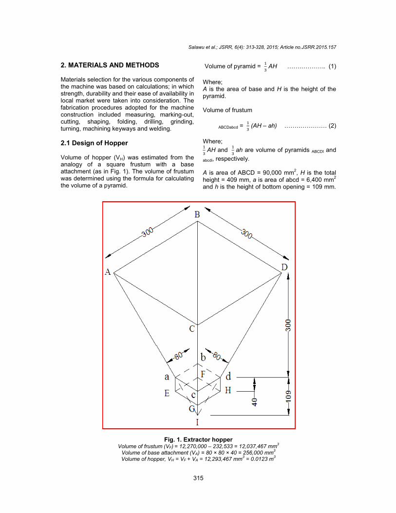
2.1 Design of Hopper Volume of hopper (VH) was estimated from the analogy of a square frustum with a base attachment (as in Fig. 1). The volume of frustum was determined using the formula for the volume of a pyramid.
Volume of frustum (VVolume of base attachment (VVolume of hopper, V
Salawu et al.; JSRR, 6(4): 313-328, 2015; Article no.
315
2. MATERIALS AND METHODS
Materials selection for the various components of as based on calculations; in which
strength, durability and their ease of availability in local market were taken into consideration. The fabrication procedures adopted for the machine construction included measuring, marking-out,
, drilling, grinding, turning, machining keyways and welding.
) was estimated from the analogy of a square frustum with a base
. The volume of frustum was determined using the formula for calculating
Volume of pyramid = �
� AH ……………….
Where; A is the area of base and H is the height of the pyramid. Volume of frustum
ABCDabcd = �
� (AH – ah) …………………
Where; �
� AH and
�
� ah are volume of pyramids
abcdi, respectively. A is area of ABCD = 90,000 mm2
height = 409 mm, a is area of abcd = 6,400 mmand h is the height of bottom opening = 109 mm.
Fig. 1. Extractor hopper Volume of frustum (VF) = 12,270,000 – 232,533 = 12,037,467 mm
3
Volume of base attachment (VA) = 80 × 80 × 40 = 256,000 mm3
Volume of hopper, VH = VF + VA = 12,293,467 mm3 = 0.0123 m
3
, 2015; Article no.JSRR.2015.157
………………. (1)
is the height of the
………………… (2)
ume of pyramids ABCDI and
2, H is the total is area of abcd = 6,400 mm
2
is the height of bottom opening = 109 mm.
Salawu et al.; JSRR, 6(4): 313-328, 2015; Article no.JSRR.2015.157
316
2.2 Determination of Volume of Barrel for JCS Pressing
To determine the volume of barrel required for seeds’ pressing, the following design requirements and calculations were established:
[i] Diameter of press barrel, DPB = 100 mm; [ii] Length of press barrel, LPB = 390 mm; [iii] Thread (screw winding) breadth, B = 7
mm. The geometric mean diameter, Dg of JCS ranges between 10.46 – 12.62 mm [18]. The thread pitch should be able to accommodate all the ranges of Dg of JCS;
[iv] Thread pitch, Tp = 15 mm; [v] Considering a tapered screw shaft with
outside diameter of 90 mm; [vi] Root diameter of screw shaft at intake =
70 mm; [vii] Root diameter of screw shaft at exit = 80
mm; [viii] Root diameter of screw winding at
midpoint, d1 = 85 mm; [ix] Thickness of screw winding at intake, ti =
10 mm; [x] Thickness of screw winding at exit, te = 5
mm; [xi] Average thickness of screw winding, t =
��� ��
� = 7.5 mm, and
[xii] Length of shaft covered with screw, L1 = 380 mm.
Total number of screw windings on the screw shaft
= ��
� � �� ………………… (3)
= ���
���� = 17.3
≈18 windings [should be whole number]
The perimeter (or length) of a screw winding was determined using the formula for calculating the circumference of a circle.
Circumference of a circle = π d …………… (4)
Where; d is diameter of the circle. Perimeter or length of a screw winding,
L = π × 85 = 267.04 mm For the determination of volume of a screw winding, the formula for calculating the volume of a cuboid was used.
Volume of a cuboid = L × B × h ..……… (5) Where; L, B and h are length, breadth and height or thickness of the cuboid, respectively. Volume of a screw winding,
VSW = L × B × t = 267.04 × 7 × 7.5 = 14,019.6 mm3
Volume of 18 screw windings, 18 VSW = 252,352.8 mm
3
In determining the volume of screw shaft (VSS) and the inner volume of press barrel, the formula for calculating the volume of a cylinder were used.
Volume of a cylinder = π r2 h …………… (6)
Where; r and h are the radius and height of the cylinder respectively. VSS considering root diameter = π r1
2 l1 ….. (7) Where; r1 and l1 are the root radius of screw winding at midpoint and the length of shaft covered with screw, respectively.
VSS considering root diameter = π × (��
�)2 × 380
= 2.156 × 10⁶
mm3
Inner volume of press barrel = π r2
2 l2 …. (8)
Where; r2 and l2 are the radius and length of press barrel respectively. Inner volume of press barrel = π × 502 × 390
= 3.063 × 106 mm
3
Inner vol. of PB occupied by screw shaft = Vol. of 18 screw windings + Vol. of screw shaft considering the root diameter ………… (9) = 2.524 × 10
5 + 2.156 × 10
6 mm
3
= 2.408 × 10⁶
mm3
Inner vol. of barrel for JCS pressing = Inner vol. of barrel – Inner vol. of barrel occupied by screw shaft ……………………………………… (10) = 3.063 × 10⁶ – 2.408 × 106
= 6.55 × 105 mm3 = 655 cm3 [vol. for seed pressing]
Salawu et al.; JSRR, 6(4): 313-328, 2015; Article no.JSRR.2015.157
317
Bulk density of JCS = 400 kg/m3 [18]
If the volume of JCS can be reduced by half (�
�)
by crushing and pressing, its bulk density after pressing, ρba will be twice of its bulk density before pressing, ρbb. Therefore, the mass of JCS that barrel can accommodate, (which can be expressed as M = ρba × Inner vol. of barrel for JCS pressing) will be equal to (0.8 × 655) = 524 g.
2.3 Power Required for Moving and Rotating of Screw Shaft, P SSMR
The power required for continuous moving and rotating of screw shaft can be estimated using equation 11, while the torque developed can be obtained using equation 12 [20].
P = � � � �
�� ………………… (11)
T = Fr ……...…..……… (12)
Where; F, N and r are the weight of screw shaft (187.5 N), screw shaft speed (50 rpm), and radius of
screw shaft (�.��
� m), respectively.
From equation 12; T = 8.44 Nm
P SSMR = � π � �� � �.��
�� = 44.18 Watts
2.4 Power Required for Transporting JCS in the Press Barrel, P Transport
Indeed, 1,000 mass unit of JCS will have a mass of 578.04 g [18], such that the weight of 1 unit of
JCS will be equal to �.��
�,��� × 9.81 = 5.69 × 10
-3 N
Based on the design’s throughput capacity of 50
kg/hr, ��,���
�,��� g of JCS can be processed per
second.
This implies that ��.�
�.�� seeds are transported per
second, and (24 × 3,600) = 86,400 seeds are transported per hour.
T = 5.69 × 10⁻³ × �.��
� = 2.56 × 10⁻⁴ Nm
P = � π � �� � �.�� � ����
�� = 1.34 × 10⁻³
Considering a coefficient of static friction of 0.48
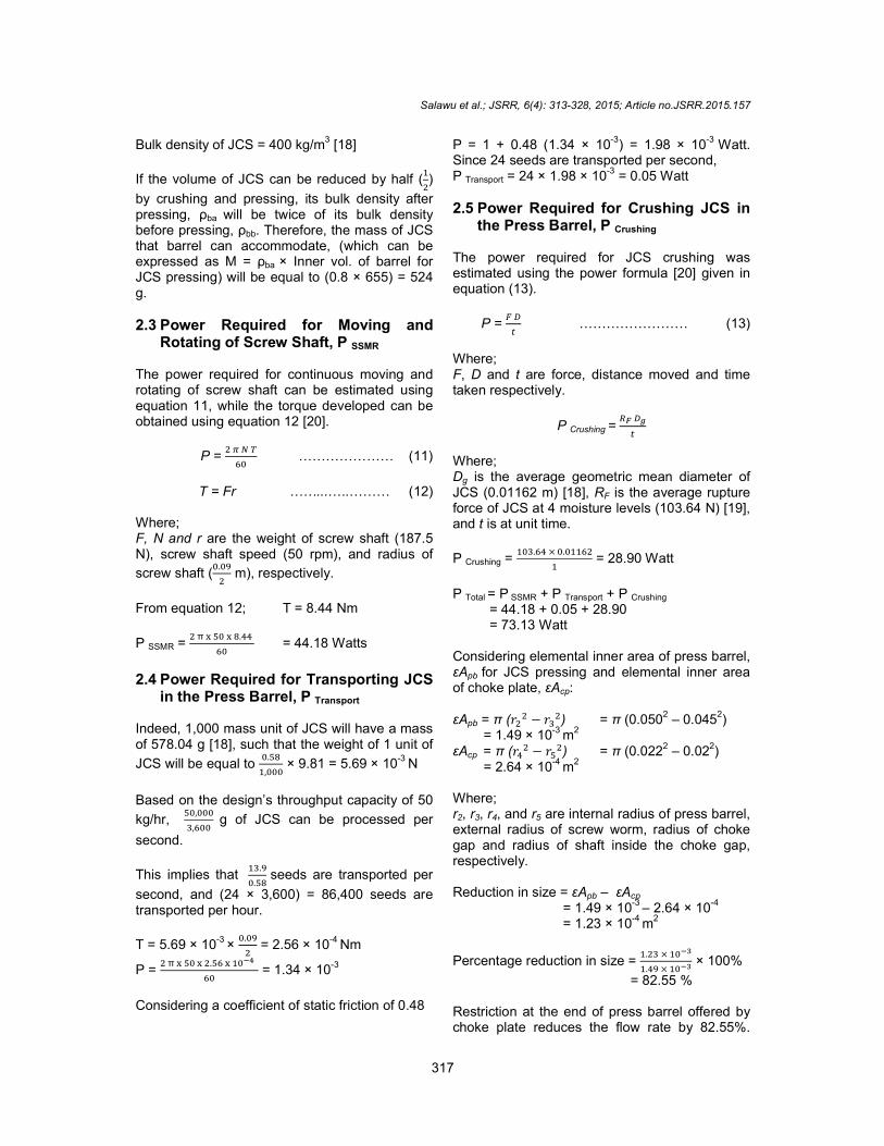
P = 1 + 0.48 (1.34 × 10⁻³
) = 1.98 × 10⁻³
Watt. Since 24 seeds are transported per second, P Transport = 24 × 1.98 × 10
-3 = 0.05 Watt
2.5 Power Required for Crushing JCS in the Press Barrel, P Crushing
The power required for JCS crushing was estimated using the power formula [20] given in equation (13).
P = � �
� …………………… (13)
Where; F, D and t are force, distance moved and time taken respectively.
P Crushing = �� ��
�
Where; Dg is the average geometric mean diameter of JCS (0.01162 m) [18], RF is the average rupture force of JCS at 4 moisture levels (103.64 N) [19], and t is at unit time.
P Crushing = ���.�� × �.�����
� = 28.90 Watt
P Total = P SSMR + P Transport + P Crushing
= 44.18 + 0.05 + 28.90 = 73.13 Watt Considering elemental inner area of press barrel, εApb for JCS pressing and elemental inner area of choke plate, εAcp: εApb = π (��
� − ���) = π (0.050
2 – 0.045
2)
= 1.49 × 10⁻³ m2 εAcp
= π (��� − ��
�) = π (0.0222 – 0.022) = 2.64 × 10
-4 m
2
Where; r2, r3, r4, and r5 are internal radius of press barrel, external radius of screw worm, radius of choke gap and radius of shaft inside the choke gap, respectively. Reduction in size = εApb – εAcp
= 1.49 × 10⁻³
– 2.64 × 10-4
= 1.23 × 10⁻⁴
m2
Percentage reduction in size = �.�� × ����
�.�� × ���� × 100%
= 82.55 % Restriction at the end of press barrel offered by choke plate reduces the flow rate by 82.55%.

Salawu et al.; JSRR, 6(4): 313-328, 2015; Article no.JSRR.2015.157
318
Hence, the total power obtained should be increased to achieve the design throughput. Assuming that total power, P Total should be increased by multiplying it with 0.4 of percentage reduction in choke plate; Design power, P Design = 0.4 × 82.55 × P Total
= 2,417 Watt ≈ 2.4 kW
2.6 Determination of Belt Tension
P = (T1 – T2) V ……………..... (14)[20] Where; P is the design power in Watt, T1 and T3 are belt tension at tight side, T2 and T4 are belt tension at slack side in Newton, and V is the speed of belt in m/s.
N1 D1 = N2 D2 1440 × 0.1 = N2 × 0.3
=> N2 = 480 rpm
N2 D2 = N3 D3 480 × 0.15 = N3 × 0.3
=> N3 = 240 rpm Where; N1, N2 & N3 are speed at; prime mover, speed reduction shaft & screw shaft, respectively [rpm] D1, D2 & D3 are diameter of pulley at; prime mover, speed reduction shaft & screw shaft respectively [m].
Belt speed, V = � � �
�� [20]
V = 7.54 m/s [Main driver] V = 3.77 m/s [Auxiliary driver]
2.7 Determination of Angle of Wrap
θ = [180 – 2sin-1
( � � �
�� )]
�
��� …..… (15)[20]
Where; θ, D, d and C are the angle of wrap [rad], diameter of the driven pulley [mm], diameter of the driver pulley [mm] and centre distance between the driver & the driven pulley [mm], respectively. Considering speed reduction shaft,
θ = [180 – 2sin-1
(��� � ���
� � ��� )]
π
���
= 2.83 rad
Considering screw shaft,
θ = [180 – 2sin-1 (��� � ���
� � ��� )]
π
���
= 2.87 rad
Recall: Design power, P = 2,400 W Considering the horizontal drive, [Main driver] 2,400 = (T1 – T2) 7.54
T1 – T2 = 318.30 N ................... (16)
2.3 log (��
��) = µ θ cosec β .............. (17)
Where; µ, θ, and β are the frictional co efficient of belt and pulley (0.4) [20], angle of wrap (2.83 rad), and half of groove angle (17.5
0), respectively.
log (��
��) =
µ θ ����� β
�.�
T1 = 43.32 T2 .......................... (18)
Substitute T1 = 43.32 T2 in equation 16 42.32 T2 = 318.30 N T2 = 7.52 N From equation 18, T1 = 325.77 N
T = T1 + Cf …..……............ [20] (19)
Cf = MV2 ………............... [20] (20)
M = ½ (W1 + W2) t × ρ ……… [20] (21)
Where; T, Cf and M are the maximum tension [N], centrifugal force on belt [N] and belt mass per meter [kg/m], respectively.
Using standard V- Belt of “type A”; W1, top width of belt = 17 mm; W2, bottom width of belt = 9.5 mm; t, belt thickness = 11 mm; and ρ, mass density of belt = 1,250 kg/m3 [20].
From equation (21), M = 0.1822 kg/m From equation (20) Cf = 0.1822 × 7.54
2
= 10.36 N From equation (19), T = 325.77 + 10.36
= 336.13 N
Considering vertical drive, [Auxiliary drive] P = (T3 – T4) 3.77 2,400 = (T3 – T4) 3.77
Salawu et al.; JSRR, 6(4): 313-328, 2015; Article no.JSRR.2015.157
319
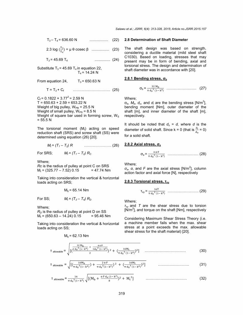
T3 – T4 = 636.60 N .................. (22)
2.3 log (��
��) = µ θ cosec β ................. (23)
T3 = 45.69 T4 ............... (24)
Substitute T3 = 45.69 T4 in equation 22,
T4 = 14.24 N From equation 24, T3 = 650.63 N
T = T3 + Cf ………………………… (25) Cf = 0.1822 × 3.77
2 = 2.59 N
T = 650.63 + 2.59 = 653.22 N Weight of big pulley, WPB = 25.5 N Weight of small pulley, WPS = 8.5 N Weight of square bar used in forming screw, WS = 55.5 N The torsional moment (Mt) acting on speed reduction shaft (SRS) and screw shaft (SS) were determined using equation (26) [20].
Mt = (T1 – T2) R …………………. (26)
For SRS; Mt = (T1 – T2) RC
Where; Rc is the radius of pulley at point C on SRS Mt = (325.77 – 7.52) 0.15 = 47.74 Nm
Taking into consideration the vertical & horizontal loads acting on SRS;
Mb = 65.14 Nm
For SS; Mt = (T3 – T4) RD Where; RD is the radius of pulley at point D on SS Mt = (650.63 – 14.24) 0.15 = 95.46 Nm
Taking into consideration the vertical & horizontal loads acting on SS;
Mb = 62.13 Nm
2.8 Determination of Shaft Diameter The shaft design was based on strength, considering a ductile material (mild steel shaft C1030). Based on loading, stresses that may present may be in form of bending, axial and torsional stress. The design and determination of shaft diameter was in accordance with [20]. 2.8.1 Bending stress, σb
σb = �� ��
π ��� (�� ��)
…………………… (27)
Where; σb, Mb, do, and di are the bending stress [N/m
2],
bending moment [Nm], outer diameter of the shaft [m], and inner diameter of the shaft [m], respectively. It should be noted that do = d, where d is the
diameter of solid shaft. Since k = 0 (that is ��
�� = 0)
for a solid shaft.
2.8.2 Axial stress, σa
σa = � α �
π ��� (�� ��)
……….…………… (28)
Where; σa, α, and F are the axial stress [N/m
2], column
action factor and axial force [N], respectively
2.8.3 Torsional stress, τxy
τxy = ���
π ��� (�� ��)
……………………. (29)
Where; τxy and T are the shear stress due to torsion [N/m
2], and torque on the shaft [Nm], respectively
Considering Maximum Shear Stress Theory (i.e. a machine member fails when the max. shear stress at a point exceeds the max. allowable shear stress for the shaft material) [20].
τ allowable = �[(
�� ��
π ���
��� ��� �
� α �
�
��� ���
�) � + (
����
π ��� (�� ��)
)�] …………………………… (30)
τ allowable = �[(����
π ���(�� ��)
) + � α �
π ���(�� ��)
) � + (����
π ��� (�� ��)
)�] ……………………. (31)
τ allowable = ��
π ���(�� ��)
�[(M� + α � �� (�� ��)
�)� + M�
�] …………………………… (32)

Salawu et al.; JSRR, 6(4): 313-328, 2015; Article no.JSRR.2015.157
320
Shafts are normally acted upon by gradual and sudden loads [20]. Hence, equation 32 can be modified to equation 33 by considering a suitable load factors.
τ allowable = ��
π ���(�� ��)
�[(K�M� + α � �� (� � ��)
�)� + (K� M� )�] …………………… (33)
Where; Kb = Combined shock and fatigue factor applied to bending moment = 1.5 to 2.0 for load suddenly applied with minor shock Kt = Combined shock and fatigue factor applied to torsional moment = 1.0 to 1.5 for load suddenly applied with minor shock
Since shafts under consideration are solid shafts; k = 0,
τ allowable = ��
π �� �[(K�M� + α � �
� )� + (K� M� )�] …………………………… (34)
d3 =
��
π τ���������
�[(K�M� + α � �
� )� + (K�M�)
�] ……………... …………………….. (35)
Since no axial stress acts on SRS, (α � �
�)� becomes zero, hence equation 35 becomes equation 36
d3 =
��
π τ���������
�[(K�M�)� + (K�M�)�] …………………….................................... (36)
Considering a mild steel shaft CS 1030 with keyway The ultimate strength, Su and yield strength, Sy of the steel CS 1030 are: Su = 500 × 106 N/m2
Sy = 250 × 106 N/m
2
τ allowable of CS 1030 = 18 % of Su = 90 × 106 N/m
2
τ allowable of CS 1030 = 30 % of Sy = 75 × 106 N/m2
Allowable shear stress of 75 × 106 N/m2 is selected for the design. There is presence of keyway on the shaft, hence; the allowable shear stress with allowance for keyway, (τ allowable +
keyway) can be express as [20]: τ allowable + keyway = (1 – 0.25) × 75 × 10
6
= 56.25 × 10⁶
N/m2
Diameter of Speed Reduction Shaft (SRS);
d3=
��
π × ��.�� × ��� �(2.0 × 65.14)� + (1.5 × 47.74 )�
d = 0.02379 m = 23.79 mm
d = 23.79 × 1.5 = 35.69 mm (…considering factor of safety of 1.5) d = 40 mm (Nearest available shaft diameter to 35.69 mm) For screw shaft diameter determination; assuming the axial force acting is very small,
then (α � �
�)� can be approximate to be zero in
equation 35.
d3=
��
π × ��.�� ×��� �(2.0 × 62.13 )� + (1.5 × 95.46)�
= 1.7166 × 10⁻⁵ m3 d
= 0.02580 m = 25.80 mm
d = 25.80 × 1.5 = 38.70 mm (… considering factor of safety of 1.5) d = 40 mm is the nearest available shaft diameter to 38.70 mm 2.9 Machine Construction The main components of the developed machine were the frame, hopper, slide rails, feed rate control device, screw shaft, speed reduction shaft, press barrel, choke plate, choke plate hanger, oil outlet, cake outlet, pulleys, pillow bearings, V-belts, prime mover seat, and prime mover. The front elevation and the side view of the developed machine are as shown in Figs. 2 and 3, respectively. The outlines of the procedure used for the construction of the components of the machine were as follows: 2.9.1 Frame The frame was constructed from 45 × 45 × 4 mm mild steel (MS) angle iron. The choice of MS was based on its moderate strength with good

weldability. The frame serves as the skeleton for other parts, and a means of coupling the parts together. The frame stand, frame support support 2, and frame support 3 had a length of 600 mm, 240 mm, 480 mm, and 550 mm, respectively. They were welded together to form the frame. 2.9.2 Hopper A square frustum-shaped hopper was constructed and mounted at the intake of the press barrel. It was constructed from 2 mm thick MS sheet. The height, top (inlet) opening and bottom (exit) opening to press barrel are 300 mm, 300 mm × 300 mm, and 80 mm × 80 mm, respectively. Provision for feeddevice and two slide rails (on which the feed rate control device moves) are provided. By this means, the quantity of seeds entering into the press barrel per unit time can be regulated. 2.9.3 Screw shaft A tapered screw shaft was used for the design. It was used because it has a high rate of pressure increase along the shaft. The length of the screw was 380 mm with outside diameter of 90 mm which was constant throughout the length. The root diameter was inclined through the screw with thread depth decreases continuously along the screw shaft. The thread depth, screw pitch
Fig. 2. Front elevation of JCS oil extraction
machine
Salawu et al.; JSRR, 6(4): 313-328, 2015; Article no.
321
The frame serves as the skeleton for er parts, and a means of coupling the parts
together. The frame stand, frame support 1, frame had a length of
600 mm, 240 mm, 480 mm, and 550 mm, welded together to form
shaped hopper was mounted at the intake of the
It was constructed from 2 mm thick MS sheet. The height, top (inlet) opening and bottom (exit) opening to press barrel are 300
mm × 300 mm, and 80 mm × 80 mm, Provision for feed-rate control
device and two slide rails (on which the feed rate control device moves) are provided. By this means, the quantity of seeds entering into the
per unit time can be regulated.
apered screw shaft was used for the design. It was used because it has a high rate of pressure increase along the shaft. The length of the screw was 380 mm with outside diameter of 90 mm which was constant throughout the length. The
ned through the screw with thread depth decreases continuously along the screw shaft. The thread depth, screw pitch
and the clearance of the screw from the press barrel were established in relationship to JCS axial dimensions [18]. Thread depth at the intaand exit were 10 mm and 5 mm, respectively. The thread thickness and the pitch of the screw were 7 mm and 15 mm, respectively. The total length of the shaft was 650 mm with a diameter of 40 mm based on bending and torsion moment analysis. The screw winding covered a length of 380 mm, leaving a clearance of 75 mm and 195 mm for seed intake and pressed cake outlet side, respectively. These clearances facilitate mounting of bearings and pulleys. 2.9.4 Speed reduction shaft, SRS A mild steel shaft (CS 1030) was used as SRS. The shaft had a total length of 340 mm with diameter of 40 mm. At left side end, 45 mm length was stepped down to 30 mm diameter, at a length of 195 from the left side end another 45 mm length was stepped down to 30 mm diameter. The shaft section with 30 mm diameter was used for pillow bearings mounting while the remaining 100 mm length of the shaft (right side end) was stepped down to 25 mm diameter for the mounting of pulleys. Two pulleys of different diameters (φ 150 mm and φ 300 mm) mounted on the SRS. One of the pulleys (φ 300 mm) was meant for speed reduction and the other pulley (φ 150 mm) served as the driver for the screw shaft.
oil extraction
Fig. 3. Side view of JCS oil extramachine
, 2015; Article no.JSRR.2015.157
clearance of the screw from the press barrel were established in relationship to JCS
Thread depth at the intake and exit were 10 mm and 5 mm, respectively. The thread thickness and the pitch of the screw were 7 mm and 15 mm, respectively. The total length of the shaft was 650 mm with a diameter of 40 mm based on bending and torsion moment
ing covered a length of 380 mm, leaving a clearance of 75 mm and 195 mm for seed intake and pressed cake outlet side, respectively. These clearances facilitate
SRS
0) was used as SRS. The shaft had a total length of 340 mm with diameter of 40 mm. At left side end, 45 mm length was stepped down to 30 mm diameter, at a length of 195 from the left side end another 45 mm length was stepped down to 30 mm
ft section with 30 mm diameter was used for pillow bearings mounting while the remaining 100 mm length of the shaft (right side end) was stepped down to 25 mm diameter for the mounting of pulleys. Two pulleys of different diameters (φ 150 mm and φ 300 mm) were mounted on the SRS. One of the pulleys (φ 300 mm) was meant for speed reduction and the other pulley (φ 150 mm) served as the driver for
oil extraction

Salawu et al.; JSRR, 6(4): 313-328, 2015; Article no.JSRR.2015.157
322
2.9.5 Press barrel, PB
It was the housing for the screw shaft. Galvanized steel (GS) pipe was used for PB. The length, internal diameter and thickness were 390 mm, 100 mm and 5 mm, respectively. 80 mm × 80 mm opening for mounting of hopper was machined from 20 mm distance at the beginning of the barrel. Oil drain holes of 3 mm diameter were drilled at the bottom mid zone of the barrel with centre to centre spacing of 20 mm in zigzag manner.
2.9.6 Choke plate
It provided restriction at the end of PB. It was connected to the end of the PB with four (4) M17 bolts and nuts. The choke plate was made from GS plate. It had a dimension of 140 mm × 140 mm × 5 mm. A centre bore of diameter 44 mm was machined on the choke plate. With a centre bore of diameter 44 mm, a choke gap of 2 mm was produced when a 40 mm diameter shaft of the screw was inserted.
2.9.7 Choke plate hanger
Four (4) choke plate hangers (CPHs) were welded to each end of the PB at the circumference. They were made from 45 mm × 45 mm × 5 mm MS angle iron. The CPHs have lengths of 50 mm each with a centre drilled hole of 15 mm diameter. The drilled holes were used to secure choke plate to the PB with four (4) M17 bolts and nuts for each plate.
2.9.8 Oil outlet
It was located below the PB. A GS sheet of 2 mm thickness was used to form it. The oil outlet was made up of oil channel, 2 side plates, drain pipe and diverge pipe. The oil channel was U–shaped, inclined at angle of 16º to the horizontal. It had an internal diameter of 110 mm and length of 240 mm. Each of the side plates comprised of two sections, a semi circular and a rectangular section. The drain pipe and the diverge pipe were made of 50 mm internal diameter pipe with length of 60 mm and 300 mm, respectively. The drain pipe serves as intermediary between oil channel and diverge pipe. Drain pipe was welded vertically below the oil channel’s exit while the diverging pipe was horizontally welded to the drain pipe. The diverging pipe carries the oil to final destination where the oil can easily be collected.
2.9.9 Cake outlet The cake outlet was located at the end of the PB. A rectangular channel with open ends was used for cake outlet and it was made from MS of 2 mm thickness. The length, breadth and vertical height of the channel were 100 mm, 50 mm and 450 mm, respectively. The cake outlet channel extended from the choke plate and was vertically positioned downward. 2.9.10 Pulley Cast iron pulleys were used for the transmission of power. Cast iron pulleys were selected because of their low cost of production with good machinability quality. Three pulleys were used. Two of these pulleys (φ 300 mm and φ 150 mm) were fixed on the SRS while the third pulley of 300 mm diameter was fixed on the SS. The pulley with diameter 300 mm on the SRS was connected to the prime mover through V-belt. The second pulley (φ 150 mm) on the SRS was connected to the SS pulley (φ 300 mm) via a V-belt. 2.9.11 Pillow bearings They were the most commonly used type of mounting units, designed to provide shaft support where the mounting surface is parallel to the shaft axis. Pillow bearings were selected because they can be used for light to heavy duty applications. Four (4) pillow bearings of 30 mm internal bore diameter for shaft were used. 2.9.12 V-Belt The selection of V-Belt for power transmission was based on: (i) the type of work to be done, (ii) power rating & speed (rpm) of the driver, (iii) speed of the driven machine / required speed ratio, and (iv) the approximate centre distance required. V-Belts of “type A” were used because their features were in-line with the design requirements [21]. 2.9.13 Prime mover Selection of prime mover was guided by the power requirements for driving the machine, transporting JCS in the PB, crushing JCS, and exerting adequate pressure for oil extraction and ejecting of press cake from the PB. Three horse power (2.6 kW) diesel prime mover was recommended to power the extraction machine based on design calculation. However, five horse

Salawu et al.; JSRR, 6(4): 313-328, 2015; Article no.JSRR.2015.157
323
power (3.7 kW) diesel prime mover was the minimum available in the local market and therefore can be used to power the oil extractor.
2.9.14 Prime mover seat
This was designed with bolt slot that can accommodate both the diesel engine and electric motor. The design was to allow the machine to be powered by either diesel engine or electric motor.
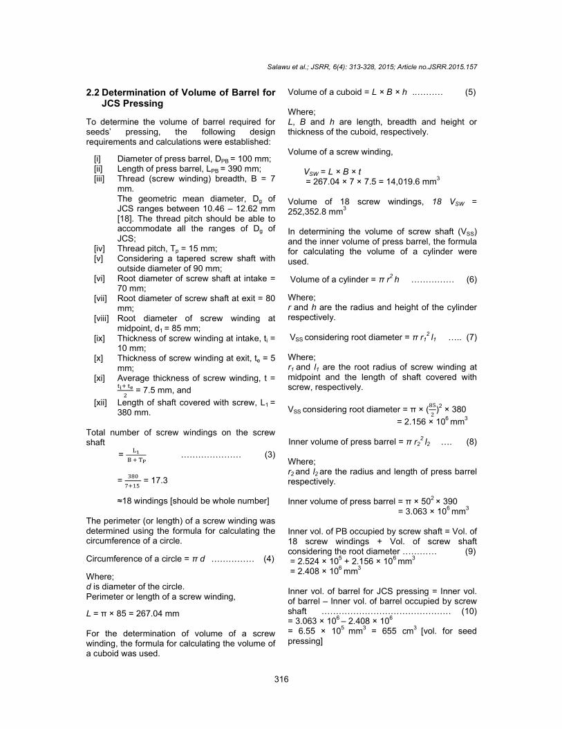
The developed Jatropha curcas seeds oil extraction machine is shown in Fig. 4.
2.10 Production Cost
The production cost of the developed prototype of J. curcas seeds oil extraction machine is approximately ₦105,010.00 (US dollars 636.42).
2.11 Machine Performance Evaluation 2.11.1 Choice of experimental factors
2.11.1.1 Moisture content
Selection of moisture content was guided by [14]. Three moisture levels of JCS (7.0, 10.0 and 13.0% db) were used for the experiment.
2.11.1.2 Feed rate
Preliminary investigations were conducted to select the range of feed rate. The minimal feed rate of JCS selected was 36 kg/hr, with successive increment of 12 kg; at feed rate of 72 kg/hr prime mover stalled and went off. Therefore, the three levels of feed rate chosen were 36, 48 and 60 kg/hr. 2.11.1.3 Machine speed Rotational speed of screw shaft that have been used for JCS oil extraction range between 25 and 55 rpm [13,14]. During preliminary investigations to select the range of speed, at speed of 30 and 35 rpm the machine went off repeatedly when the feed rate was raised from 36 kg/hr to 60 kg/hr. At speed of 40 rpm, the machine operates smoothly. Three levels of speed chosen for the experiment were 40, 50 and 60 rpm. 2.11.2 Performance indicators The performance indicators that were evaluated are the throughput capacity, extraction rate, and extraction efficiency.
2.11.2.1 Throughput capacity
It quantifies the machine's capability in terms of quantity of JCS it can process per unit time. It can be quantified using the [13] relationship as stated in equation 37.
Throughput capacity = �
� [kg/hr] ………. (37)
Where; M = Mass of seeds processed [kg] T = Time taken for expelling [hr]
2.11.2.2 Extraction rate
It quantifies the volume of oil that the machine is capable of expelling per unit time.
Extraction rate = ��
� [l/hr] ………. (38)
Where; VO = Volume of oil extract [l]
2.11.2.3 Extraction efficiency
It depicts the level of effectiveness of the developed machine comparing the volume of oil extracted to the volume of extractable oil in the processed seed. It can be quantified using the [22] relationship as in equation 39:
Extraction efficiency =
��
�� × 100 [%] …….. (39)
Where; YO = Mass of oil extract [kg] EO = Expected oil (or Extractable oil) [kg]
= Percentage oil content × Mass of seeds processed [kg]
= 0.35 × Mass of seeds processed [kg]
The oil content of J. curcas seeds ranges between 30 – 40% [4]. The average was assumed for purpose of computation.
2.11.3 Experimental design
The experiment was conducted using 3 × 3 × 3 factorial experimental design at three levels of; speed (S1 = 40, S2 = 50, & S3 = 60 rpm), feed-rate (F1 = 36, F2 = 48, & F3 = 60 kg/hr), and moisture content (M1 = 7.0, M2 = 10.0 & M3 = 13.0% db). Each of the experimental treatment units was subjected to three replications.
3. RESULTS AND DISCUSSION The mean value of machine’s performance is shown in Table 1.

Salawu et al.; JSRR, 6(4): 313-328, 2015; Article no.JSRR.2015.157
324
Fig. 4. The developed prototype of Jatropha curcas seeds oil extraction machine
3.1 Throughput The analysis of variance showed that the (all the main effects) screw speed (S), feed-rate (F) and moisture content (M) significantly affected throughput (Table 2) (P=0.01). The effect of speed was the most significant, followed by feed-rate, and moisture content. Among the first-order interactions, the order of importance was FM, SM and SF all being significant (P =0.05). In the second-order interactions, SFM was not significant (P <0.05). The throughput of the machine increased as speed increased. Similar trend has been reported [23]. The increase in throughput may be attributed to the fact that, as the speed increases, the rate at which the seeds are transported into the press barrel per unit time increases. At high speed, the retention time of feed-stock in the press barrel is shortened, therefore the amount of feed-stock (JCS) processed per unit time increased, and this is evident in these results. Further analysis using LSD revealed that the mean throughput at speed
of 60 rpm is statistically higher than those for speed 50 and 40 rpm. The mean throughput for speed 50 rpm is also statistically higher than that of 40 rpm (Table 3).
The significant difference in the throughput as feed-rate increased can be attributed to the fact that the quantity of JCS been introduced to the press barrel has increased, and consequently more quantity of seeds are processed which account for increase in the throughput. Further analysis using LSD revealed that throughput at 60 kg/hr is different statistically from the mean throughput at 48 and 36 kg/hr. The mean throughput at 48 kg/hr is also different statistically from the mean throughput at 36 kg/hr. An average throughput of 41.88 kg/hr was recorded for the highest feed-rate, 40.05 kg/hr for the medium, while 33.21 kg/hr was obtained as the throughput for the low feed-rate. The effect of moisture content on throughput was found to be significant (P =0.01). Further analysis showed that the mean throughput at 7.0% moisture content (db) was different statistically
Hopper
Screw shaft
Prime mover
Prime mover seat
Speed reduction shaft
Cake outlet
Press barrel
Speed reduction pulley
Frame
Choke plate hanger
Pillow bearing
Choke plate
Screw shaft pulley
V-Belt
Salawu et al.; JSRR, 6(4): 313-328, 2015; Article no.JSRR.2015.157
325
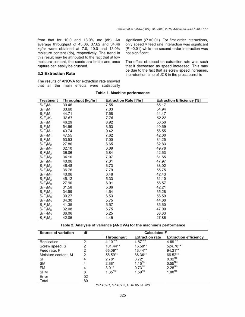
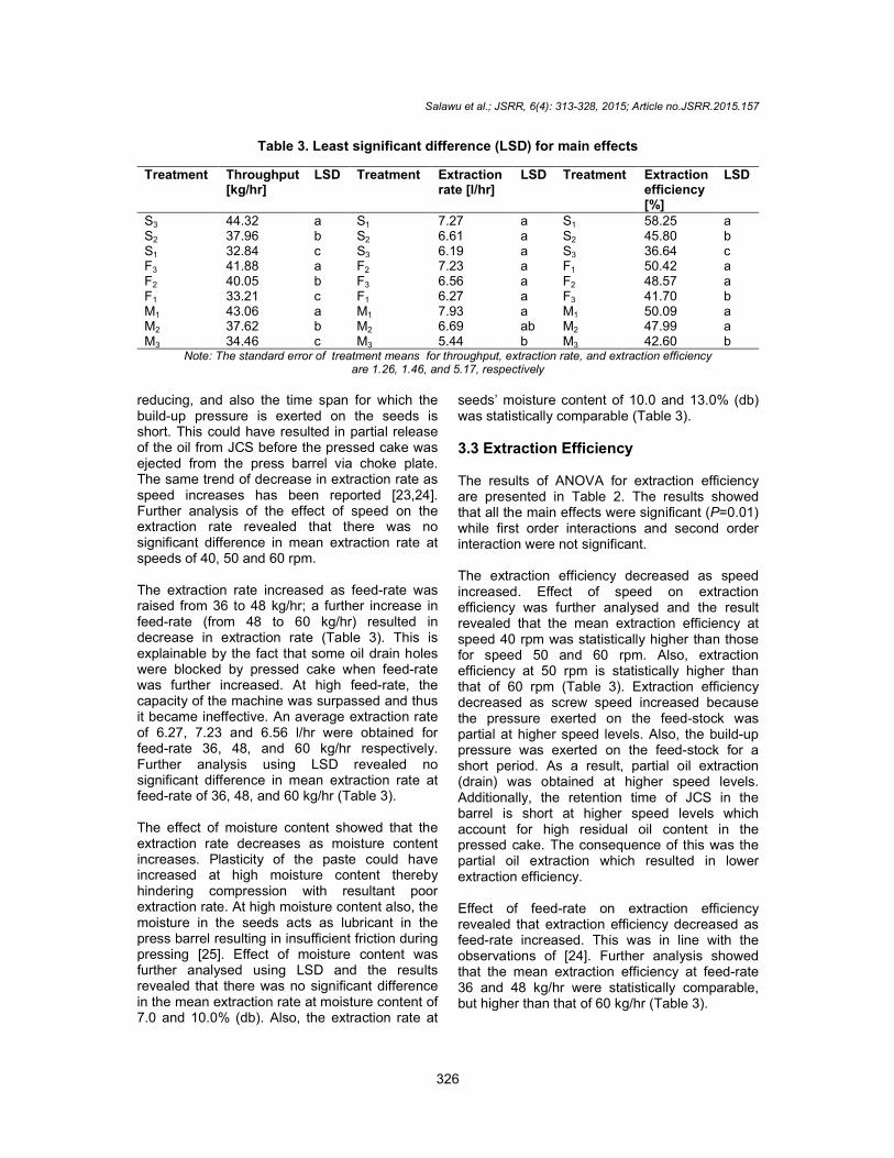
from that for 10.0 and 13.0% mc (db). An average throughput of 43.06, 37.62 and 34.46 kg/hr were obtained at 7.0, 10.0 and 13.0% moisture content (db), respectively. The trend in this result may be attributed to the fact that at low moisture content, the seeds are brittle and once rupture can easily be crushed.
3.2 Extraction Rate
The results of ANOVA for extraction rate showed that all the main effects were statistically
significant (P =0.01). For first order interactions, only speed × feed rate interaction was significant (P =0.01) while the second order interaction was not significant. The effect of speed on extraction rate was such that it decreased as speed increased. This may be due to the fact that as screw speed increases, the retention time of JCS in the press barrel is
Table 1. Machine performance
Treatment Throughput [kg/hr] Extraction Rate [l/hr] Extraction Efficiency [%] S1F1M1 30.46 7.55 65.17 S2F1M1 33.60 7.03 54.94 S3F1M1 44.71 7.58 44.47 S1F2M1 32.67 7.76 62.22 S2F2M1 46.29 8.92 50.50 S3F2M1 54.96 8.53 40.69 S1F3M1 43.74 9.42 56.55 S2F3M1 47.55 7.62 42.00 S3F3M1 53.53 7.00 34.25 S1F1M2 27.86 6.65 62.83 S2F1M2 32.10 6.09 49.78 S3F1M2 36.06 5.84 42.53 S1F2M2 34.10 7.97 61.55 S2F2M2 40.06 7.31 47.97 S3F2M2 46.48 6.73 38.02 S1F3M2 36.76 7.79 55.75 S2F3M2 40.06 6.48 42.43 S3F3M2 45.12 5.33 31.10 S1F1M3 27.90 6.01 56.57 S2F1M3 31.58 5.06 42.21 S3F1M3 34.59 4.64 35.28 S1F2M3 30.27 6.53 56.59 S2F2M3 34.30 5.75 44.00 S3F2M3 41.35 5.57 35.60 S1F3M3 32.08 5.75 47.00 S2F3M3 36.06 5.25 38.33 S3F3M3 42.05 4.45 27.86
Table 2. Analysis of variance (ANOVA) for the machine’s performance
Source of variation df Calculated F Throughput Extraction rate Extraction efficiency
Replication 2 4.10 NS 4.67 NS 4.69 NS Screw speed, S 2 101.44** 16.59** 524.78** Feed rate, F 2 65.09** 13.44** 94.31** Moisture content, M 2 58.59** 86.36** 66.52** SF 4 2.78* 3.72* 0.32NS SM 4 2.88* 1.15
NS 0.55
NS
FM 4 3.01* 0.73NS
2.28NS
SFM 8 1.35NS 1.59NS 1.08NS Error 52 Total 80
**P =0.01, *P =0.05, P <0.05 i.e. NS
Salawu et al.; JSRR, 6(4): 313-328, 2015; Article no.JSRR.2015.157
326
Table 3. Least significant difference (LSD) for main effects
Treatment Throughput [kg/hr]
LSD Treatment Extraction rate [l/hr]
LSD Treatment Extraction efficiency [%]
LSD
S3 44.32 a S1 7.27 a S1 58.25 a S2 37.96 b S2 6.61 a S2 45.80 b S1 32.84 c S3 6.19 a S3 36.64 c F3 41.88 a F2 7.23 a F1 50.42 a F2 40.05 b F3 6.56 a F2 48.57 a F1 33.21 c F1 6.27 a F3 41.70 b M1 43.06 a M1 7.93 a M1 50.09 a M2 37.62 b M2 6.69 ab M2 47.99 a M3 34.46 c M3 5.44 b M3 42.60 b
Note: The standard error of treatment means for throughput, extraction rate, and extraction efficiency are 1.26, 1.46, and 5.17, respectively
reducing, and also the time span for which the build-up pressure is exerted on the seeds is short. This could have resulted in partial release of the oil from JCS before the pressed cake was ejected from the press barrel via choke plate. The same trend of decrease in extraction rate as speed increases has been reported [23,24]. Further analysis of the effect of speed on the extraction rate revealed that there was no significant difference in mean extraction rate at speeds of 40, 50 and 60 rpm. The extraction rate increased as feed-rate was raised from 36 to 48 kg/hr; a further increase in feed-rate (from 48 to 60 kg/hr) resulted in decrease in extraction rate (Table 3). This is explainable by the fact that some oil drain holes were blocked by pressed cake when feed-rate was further increased. At high feed-rate, the capacity of the machine was surpassed and thus it became ineffective. An average extraction rate of 6.27, 7.23 and 6.56 l/hr were obtained for feed-rate 36, 48, and 60 kg/hr respectively. Further analysis using LSD revealed no significant difference in mean extraction rate at feed-rate of 36, 48, and 60 kg/hr (Table 3). The effect of moisture content showed that the extraction rate decreases as moisture content increases. Plasticity of the paste could have increased at high moisture content thereby hindering compression with resultant poor extraction rate. At high moisture content also, the moisture in the seeds acts as lubricant in the press barrel resulting in insufficient friction during pressing [25]. Effect of moisture content was further analysed using LSD and the results revealed that there was no significant difference in the mean extraction rate at moisture content of 7.0 and 10.0% (db). Also, the extraction rate at
seeds’ moisture content of 10.0 and 13.0% (db) was statistically comparable (Table 3).
3.3 Extraction Efficiency The results of ANOVA for extraction efficiency are presented in Table 2. The results showed that all the main effects were significant (P=0.01) while first order interactions and second order interaction were not significant. The extraction efficiency decreased as speed increased. Effect of speed on extraction efficiency was further analysed and the result revealed that the mean extraction efficiency at speed 40 rpm was statistically higher than those for speed 50 and 60 rpm. Also, extraction efficiency at 50 rpm is statistically higher than that of 60 rpm (Table 3). Extraction efficiency decreased as screw speed increased because the pressure exerted on the feed-stock was partial at higher speed levels. Also, the build-up pressure was exerted on the feed-stock for a short period. As a result, partial oil extraction (drain) was obtained at higher speed levels. Additionally, the retention time of JCS in the barrel is short at higher speed levels which account for high residual oil content in the pressed cake. The consequence of this was the partial oil extraction which resulted in lower extraction efficiency. Effect of feed-rate on extraction efficiency revealed that extraction efficiency decreased as feed-rate increased. This was in line with the observations of [24]. Further analysis showed that the mean extraction efficiency at feed-rate 36 and 48 kg/hr were statistically comparable, but higher than that of 60 kg/hr (Table 3).
Salawu et al.; JSRR, 6(4): 313-328, 2015; Article no.JSRR.2015.157
327
Effect of moisture content on extraction efficiency revealed that extraction efficiency decreases as moisture content increases. Further analysis using LSD revealed that extraction efficiency at 7.0 and 10.0% moisture content (db) were statistically comparable, but higher than that of 13.0% moisture content (Table 3). A decline in extraction efficiency as moisture content increases can be attributed to the fact that at high moisture content, there is an increase in plasticity of the seeds and thus reduced level of compression resulting in low extraction efficiency [25]. Also at high moisture content, the moisture in the seeds acts as lubricant in the press barrel resulting in insufficient friction during pressing [21]. This might also be the cause of low extraction efficiency recorded at high moisture levels.
4. CONCLUSION Since Jatropha curcas seeds oil is essential for production of an environmental friendly fuel that can substitute fossil fuel, a cost effective small scale JCS oil extraction machine was designed, developed and evaluated. Presently, the targeted users of the developed prototype machine are the cottage industries. Cottage industries are targeted because they require minimal investment to set up, production is flexible (allowing persons to work at their own pace), and it is a possible answer to the unemployment problem plaguing many Nigerians (as it provides a source of self-employment with income). The throughput, extraction rate and extraction efficiency of the machine was found to be in the range of 27.86 to 54.96 kg/hr, 4.45 to 9.42 l/hr, and 27.86 to 65.17%, respectively. The best throughput, extraction rate, and extraction efficiency were obtained at a speed of 40 rpm, feed-rate of 48 kg/hr and moisture content of 7.0%. The average throughput, extraction rate and extraction efficiency of the machine were 32.67 kg/hr, 7.76 l/hr, and 62.22%, respectively.
ACKNOWLEDGEMENTS The authors wish to acknowledge and express our appreciation to Mr. Ayorinde Asala (of Agric Engineering Department’s Workshop) who helped greatly in bringing the developed machine from concept to reality. His support, cooperation and assistance during the construction of the machine are highly appreciated.
COMPETING INTERESTS Authors have declared that no competing interests exist.
REFERENCES 1. Emil A, Zahira Y, Siti KK, Manal I, Jumat S.
Characteristic and composition of Jatropha curcas oil seed from Malaysia and its potential as biodiesel feedstock. European J Scientific Research. 2009;29(3):396–403.
2. Singh RK, Padhi SK. Characterization of Jatropha oil for the preparation of biodiesel. Natural Product Radiance. 2009; 8(2):127–132.
3. Gubitz GM, Mittelbach M, Trabi M. Exploitation of the tropical oil seed plant Jatropha curcas L., Bioresource Tech. 1999;67:73–82.
4. Forson FK, Oduro EK, Donkoh EH. Performance of Jatropha oil blends in a diesel engine. Renewable Energy. 2004; 29: 1135–1145.
5. GANBC. Jatropha World. The Global Authority on Non-food Biodiesel Crop. Indian Program on Biodiesel Publication; 2009. Available:http://www.jatrophabiodiesel.org/global-algae-worldindia.html [Accessed February 21, 2011]
6. Haque MA, Islam MP, Hussain MD, Khan F. Physical, mechanical properties and oil content of selected indigenous seeds available for biodiesel production in Bangladesh. Agric Eng International: the CIGR Ejournal. Manuscript 1419. 2009;11: 1–8.
7. Global Floral Biotech. Jatropha Seeds. 2010. Available:http://www.jatrophaseeds.com/jatropha_seeds.htm [Accessed February 22, 2011].
8. Vishnu N, Kalpak K. Jatropha Seeds. Vanashree Agriculture Pvt. Ltd (Vanashree Agrotech); 2010;
Available:http://www.vanashreeagrotech.com/jatropha.html [Accessed February 21, 2011]
9. Narayana J, Ramesh A. Parametric studies for improving the performance of a Jatropha oil-fuelled compression ignition engine. Renewable Energy. 2006;31: 1994–2016.
10. Du W, Xu Y, Liu D, Zeng J. Comparative study on lipase-catalyze transformation of

Salawu et al.; JSRR, 6(4): 313-328, 2015; Article no.JSRR.2015.157
328
soybean oil for biodiesel production with different acylacceptors. J molecular catalysis B: Enzymatic. 2004;30:125–129.
11. Khan MI, Chhetri AB, Islam MR. Community based energy model: A Novel approach in developing sustainable energy. Energy sources. 2000;69:21–25.
12. Uziak J, Loukanov IA. Performance evaluation of commonly used oil ram press machines. Agric Eng International: the CIGR Ejournal, Manuscript PM 07 019. 2007;9:12.
13. Harmanto A, Hendriadi E, Rahmarestia, Mardison, Wiyono J. Performance Test of a screw- press machine for extracting Jatropha curcas seed into crude oil as an alternative energy source. Indonesian J Agriculture. 2009;2(1):35–40.
14. Kabutey A, Herak D, Hanus J. Screw Press Performance for Oil extraction from Jatropha curcas L. Seeds of different moisture content. Scientia Agriculturae Bohemica. 2010;41(4):225–230.
15. Al Kurki, Bachmann J, Hill H. Oilseed processing for small-scale producers. ATTRA – National Sustainable Agriculture Information Service: A division of National Centre for Appropriate Technology (NCAT) United States Department of Agriculture’s Rural Business–Cooperative Service. 2008;16.
16. Singh J, Bargale PC. Development of a small capacity double stage compression screw press for oil expression. J of Food Eng. 2000;43:75–82.
17. Zheng YI, Wiesenborn DP, Tostenson K, Kangas N. Energy analysis in the screw
pressing of whole and dehulled flaxseed. J of Food Eng. 2005;66:193–202.
18. Salawu AT, Suleiman ML, Isiaka M. Physical Properties of Jatropha curcas seed. EJPAU. 2013a;16(4):#07.
19. Salawu AT, Isiaka M, Suleiman ML. Design related mechanical properties of Jatropha curcas seeds. Global J. of Eng & Applied Sciences. 2013b;3(4):199–203.
20. Khurmi RS, Gupta JK. A textbook of Machine Design. 14
th edition, Eurasian Ltd.
Ram Nagar New Delhi. 2007;1230. 21. Gates Industrial V-Belt Drive Design
Manual. Upgraded Quad-Power II V-belt. 2004;92. Available:www.mechanical-transmissions.info [Accessed October 22, 2011]
22. Bamgboye AI, Adejumo AOD. Development of a sunflower oil expeller. Agric Eng International: The CIGR Ejournal. 2007;9:1–6.
23. Boeck H. Biodiesel. It all begins with oilseed crushing and oil separation – some considerations. Paper presented at the Practical Short Course on Biodiesel, Prague, Hungary. 2005;8.
24. Karaj S, Muller J. Determination of physical, mechanical and chemical properties of seeds and kernels of Jatropha curcas L. Industrial Crops and Products. 2010;32(2):129-138.
25. Ruber M. New technologies for processing Crambe abyssinica. M. S. Thesis, Iowa State University, Ames. 1992;118.
_______________________________________________________________________________ © 2015 Salawu et al.; This is an Open Access article distributed under the terms of the Creative Commons Attribution License (http://creativecommons.org/licenses/by/4.0), which permits unrestricted use, distribution, and reproduction in any medium, provided the original work is properly cited.
Peer-review history: The peer review history for this paper can be accessed here:
http://www.sciencedomain.org/review-history.php?iid=965&id=22&aid=8441