development of biography a steel replacement … · standard ballasted deck railway bridges. ......
TRANSCRIPT

DEVELOPMENT OF A STEEL
MODULAR DECK FOR RAIL AND
HIGHWAY BRIDGES
DUNCAN PATERSON
DUNCAN PATERSON
BIOGRAPHY
Duncan Paterson, PE is a Senior Bridge Engineer with HDR Inc. in Cincinnati, OH. Dr. Paterson is a graduate of Michigan State University (BS) and Lehigh University (MS, PhD). His dissertation topic investigated the structural fatigue of naval ship hulls. He is well versed in complex analysis, design, and rehabilitation of highway and rail structures. Dr. Paterson is an active member of AREMA Committee 15– Steel Structures, and is the co-chair of NSBA Task Group 16 for Orthotropic Steel Deck Bridges. He is also a Past President of both the Cincinnati Section of ASCE, and of the ASCE Ohio Council of Sections.
SUMMARY
Replacement of deteriorated decks represents a major maintenance item, disrupts traffic, and is a routine capital investment for bridge owners. Steel decks, when properly constructed, have proven to be a more durable option than other alternates. Several variations of steel decks are currently under development for use with standard short spans. The long term goal is to develop a durable and adaptable deck system that can be utilized for a variety of superstructure configurations. The initial phase of the study, reported in this document, concentrates on standard ballasted deck railway bridges. The discussion includes the various shapes under consideration, as well as the analyses of the deck components. Presented are the fatigue design, the various options for an efficient panel weight, the comparisons against other deck panel systems, and constructability and cost considerations.
Page 1 of 11
DEVELOPMENT OF A STEEL MODULAR DECK FOR RAIL AND HIGHWAY BRIDGES
Abstract Durability of bridge decks is of vital importance to Highway and Railroad industries. Replacement of deteriorated decks represents a major maintenance item, disrupts traffic, and is a routine capital investment. Steel decks, when properly constructed, have proven to be a more durable option than other alternates. Several variations of steel decks are currently under development for use with standard short spans. The long term goal is to develop a durable and adaptable deck system that can be utilized for a variety of superstructure configurations. The proposed decks will be fabricated from plate material and common steel shapes in order to provide a long term, cost effective decking solution. The initial phase of the study, reported in this document, concentrates on standard ballasted deck railway bridges. The decks are envisioned as modular panels, individually installed, similar to precast deck panels or steel grid deck systems. As such, these panels can also be incorporated into accelerated bridge construction.
The discussion includes the various shapes and configurations being investigated. Also included are the analysis of the deck components including fatigue design, the various options for an efficient panel weight, comparisons against other deck panel systems, and constructability and cost considerations. This modular steel deck system has the potential to positively impact the steel industry. Ultimately, one could design, fabricate, and construct a completely steel bridge superstructure system for both rail and highway bridges and create a much more durable and long lasting structure.
Background On average, timber decks for Rail bridges are replaced on intervals of 10 to 15 years. Similarly, the expected life of a standard highway concrete deck is 20 to 30 years. The expected design life of a steel orthotropic deck has been equal to the design life of the structure itself, historically, 75 years. Modern expectations for steel decks are for over a 100 year design life.
In contrast to the expected life, however, when not properly installed or fabricated, steel orthotropic decks have a history of fatigue and hot-cracking related problems. This is due to the complex nature of the structural demands on the orthotropic system. Rarely, however, is strength of the orthotropic deck a controlling consideration. Steel grid decks also have issues, such as rider comfort. A modular steel deck combines the best of both orthotropic decks and modular decks in that it reduces the complexity of the system analysis, yet maintains a modular approach to construction.
Considering the analysis, similar to a one way slab design, the proposed steel deck configuration places the main load resistance transverse to the stringers. The basic geometry is shown as a sketch in Figure 1.
The idea of a flat plate steel deck is not new. Steel decks are currently used in rail construction, primarily for through plate girders (TPG) with continuous floorbeams (Figure 2). They are also found on deck plate girders (Figure 3). While TPG configurations with floorbeams are considered a standard practice, the use of steel decks with more common deck plate girders is much less common. As can be seen in Figure 3, the required beam spacing is relatively close together and additional supporting brackets are

Page 2 of 11
Figure 1. Sketch of steel deck on stringers, deck ribs (orange) are transverse to the stringers (red)
Figure 2. Through plate girder, typical steel deck with floorbeams spaced at 2ft
Figure 3. Deck Girders with steel deck and support brackets

Page 3 of 11
required to support the overhang and walkway. Alternate configurations with wider beam spacing require the deck to be transversely supported between the beams.
The initial concept that spurred a steel deck with transverse stiffeners was to eliminate the extra detailing required for the support brackets while still providing the durability of steel. The proposed deck with transverse ribs would eliminate several support details and facilitate installation.
Loads Loading is very different for rail and highway in both the scale and the positioning of the loads. The AASHTO LRFD design for decks is generally controlled by the HL-93 truck load (Figure 4) (AASHTO 2012). A truck can be positioned anywhere on a deck (within barriers), transversely
and longitudinally. Thus, analysis requires that the truck be positioned so as to create the worst case loading condition anywhere on the deck. (A refined loading pattern is provided by AASHTO 3.6.1.4.1 for Orthotropic deck design, which would be the controlling condition for this steel deck as well.) A railcar, however, is required to ride in a fixed transverse position and the worse case location is dependent on the longitudinal placement of the load. The AREMA design load is the Cooper E-80 load consist and alternate load (Figure 5) (AREMA 2013).
Another distinction between the two loads is the load path to the deck. For highway loads, the wheel load is applied directly to the deck wearing surface or overlay in accordance with AASHTO Article 3.6.1.1. A rail load, though, generally has two load transfer mechanisms to the deck. For both mechanisms, the rail is directly supported by
Figure 4. AASHTO HL-93 Truck Live Load (AASHTO, 2012)
(a) (b) Figure 5. AREMA Cooper E-80 Load (a) and alternate load (b) (AREMA 2013)

Page 4 of 11
a tie (timber, concrete, FRP, or steel). The tie, in turn, can either bear directly on a structural supporting member, or on ballast. The former is only used in practice with Timber or FRP ties that bear directly on stringers or deck girders (Figure 6) in what is called an Open Deck configuration. Thus, the deck and tie are the same member and are transverse to the main structural supporting members. In the latter, ties are supported by ballast, which in turn distributes the load to a supporting deck. A ballasted deck is generally preferred by the rail industry as it reduces impact, distributes load, and generally is easier to maintain.
Figure 6. Timber open deck on steel stringers (showing diaphragms)
For this steel deck under development, railroad loading with a ballasted deck is investigated.
For rail loading, many varying car loads are considered. As stated, the controlling design load is the Cooper E80 consist and alternate. Car loads are distributed to axles, which are in turn distributed to the wheels, wheels load the rails, rails load the ties, and lastly the ties distribute load through the ballast to the supporting deck. This distribution creates pressure bulbs below the ties as shown in Figure 7 (Hay 1982).
For modeling purposes, the controlling axle load is the Cooper E-80 80kip load spaced at 5ft. Thus, following the procedures for distribution of wheel loads in accordance with Hay, we can assume an equivalent point load located under each tie, as distributed through the ballast. Also, since the
exact location of a tie can not be predetermined, the loads are applied at the tie spacing and moved longitudinally along the deck in order to capture the worst case loading condition (Figure 8).
Cooper E80 loads are used for fatigue design with the fatigue limits calibrated for rail loads. For a refined fatigue evaluation for expected design life, AREMA 7.3.3.2 provides guidance on using actual expected rail car loading to predict the expected life of the structure. To do this, the operational planning for rail car weights needs to be applied. Rail car consists can be categorized according to car weight. Common car consists currently on rails include 315k, 286, and 263k car consists, with axle loads of 78.5k, 71.5k, and 68.5k, respectively. A similar exercise can be done for these axle loads. Or, results can be proportioned from the 80k axle as long as the distributed load is used as the ratio, and not the actual axle loads (to account for axle spacing).
Geometry The basic layout is shown in Figure 1. Figure 9 shows a sketch of the geometry used for the development design of the steel deck. The critical dimension is the stringer (or deck girder) spacing. This is effectively the unsupported length of the deck for live load. In this initial study deck girders spaced at 6ft and 9ft center-to center spacing were used to represent the anticipated practical expectations on the design.
Limited attention was given to span length. It is acknowledged that deformation of the main supporting members under load will induce compressive strain at the top flange for positive moment and tensile strains in negative movement regions. However, the attachment configuration is proposed to be such that the deck has an allowance to expand and contract in the longitudinal direction. This is accomplished via various possible attachment details to be evaluated in the future.

Page 5 of 11
Figure 7. Pressure Bulb diagrams for axle loads through ties and ballast (Hay, 1982)
Figure 8. Deck section showing rail pressure bulbs applied as longitudinal-moving point loads (support stringers not shown)

Page 6 of 11
Figure 9. Typical Section for initial steel deck
design
Strength Design For the deck girder system, the Cooper E80 loads induce various primary stress conditions that need to be evaluated:
Transverse bending of the panel between the stringers
Longitudinal and transverse bending of the deck plate
Buckling of the deck plate
Buckling of the supporting shape vertical member(s) (e.g. the shape’s web)
Shearing of the deck panel
Emphasis of this section will be given to the calculations that lead to the selection of the supporting shape for the deck to resist the maximum positive moment between the supporting stringers. The other load conditions are checked after sizing the member and then the shape is adjusted as necessary.
Required bending resistance of the deck is very dependent upon the girder spacing and the assumption of how the deck is supported. That is, the majority of the resistance is provided by the web of the supporting stringer, but the flange provides additional resistance depending on the thickness of the components and the addition of stiffeners (if any) to the stringer section. Moreover, there are the simplifying assumptions
that the deck is simply supported between points of support that are allowed for deck design.
For the development of the deck, it was evaluated in a structural model that considered the deck to be continuous over the points of support. It did not, however, consider the support effect of the flanges. This was done for ease of modeling and in consideration that the results would be slightly conservative for positive bending. Additionally, the buckling and shear of the vertical deck members would be able to be better scrutinized for the resulting concentrated load. This would also account for out-of-flatness fabrication tolerances in the flanges which could lead to the deck not being supported at the flange edges.
As stated in the Geometry section, two stringer spacings were examined. Ultimately the larger spacing was chosen from which the largest transverse moments would be generated. This configuration would serve as a proof of concept for rail live loads. The proposed deck support configuration is shown in Figure 9.
Based on the loading demands of the Cooper E80 and alternate live load distributed through the ballast, the bending moment demand is 31k-ft per foot. Thus, the required section modulus is 13.5in3 per foot (assuming a material strength of grade 50 steel) for strength. In accordance with AREMA deflection requirements, deflection is being limited on the deck to L/640, where L is the girder spacing of 9ft. The corresponding required moment of inertial is therefore 84.5in4 per foot.
Shape Options There are options as to how the strength and stiffness demands can be resisted. Several shapes were evaluated for both material and fabrication efficiency. This includes:
W-Shape
T-Shape
Structural tube

Page 7 of 11
Channel section
A combination of shapes
W-Shape Shown in Figure 10, the w-shape has the advantage of being strong, compact and an efficient section on its own. It also allows for a slightly greater spacing of the sections as the top flanges offer support to the deck plate, shortening the effective span of the plate. When considering the composite action of the steel deck plate, however, the top flange becomes superfluous, or at least inefficient. This naturally leads to evaluating a T-shape.
Figure 10. W-shape support of steel deck plate.
T-Shape The advantage of the t-shape is that, similar to an orthotropic deck, the deck plate becomes the top flange and offers good section efficiency (Figure 11). There are disadvantages to using this shape. First, the span of the plate is from stem to stem, decreasing the possible spacing of the shapes. Second, access for placing the longitudinal weld can limit section selection to shorter shapes with narrow flanges.
Figure 11. T-shape support of steel deck plate
Structural Tube The next shape considered is the structural tube, rectangular or square (Figure 12). The advantage of this shape is the additional torsional stability and an increased spacing with respect to the t-shape. The disadvantages are having an inefficient top flange, having a constant thickness that leads to inefficiencies, and having rounded edges which adds a level of weld complexity when attaching it to the deck plate.
One additional configuration that was considered was butted structural tubes; the top flange forms the deck surface. This turned out to be a less efficient design due to the number of sections required for each panel. It also placed the top butt weld of the two rounded sections in direct tension as a Category F fatigue detail.
Figure 12. Structural tube support of steel deck plate
Channels Channels offer another option (Figure 13) but have the disadvantage of being asymmetric on their vertical axes and offer less torsional stability than other options. Where channels were found to be useful, however, was at the ends of panels. They are able to minimize the unsupported edge distance.

Page 8 of 11
Figure 13. Deck showing C-shape support of steel
deck plate
Combination The goal of developing this plate and shape configuration is that engineers and fabricators need not be limited by a single shape per deck or per deck panel. As each situation presents a different set of demands, one can imagine selecting any particular shape to meet the needs with the fabrication details already established.
Selection for the proposed panel A combination of T-shapes and channels was eventually selected (Figure 8). The T-shapes are the primary shape across the panel. But, the flange of the T-shape led to larger unsupported lengths at the end of the panels. To counter this, a channel is placed at each panel with the channel web facing the edge end and placed relatively close to the edge of the plate.
The selected shapes are WT8x15.5 and C8x18.75 creating a transverse bending section modulus per foot of 23.2in3. The moment of inertia is 134in4. Thus, the demands are met for the primary strength design.
Fatigue Design Of particular importance, especially for rail decks, is fatigue. Each passing train can impart hundreds if not thousands of stress cycles. Fatigue design is done with the same axle loads as are used for strength design, the Cooper E-80 and alternate live loads. Consideration can also be given to rail operational loads, and the load frequency imposed by rail consists of heavy axle cars. The known
operating limits for the span being evaluated is a 315-kip, 4 axle car consist (78.75k per axle).
For fatigue, there are three conditions that are of particular importance. First, there is the fatigue induced by primary bending of the section. For the proposed panel in bending, the two details of concern are the flange of the shape in tension (plain steel, Cat. A) and the shape-to-deck plate weld (longitudinal fillet weld, Cat. B). Second, there is the longitudinal bending of the plate resisted by the supporting shape. This detail takes guidance from the FHWA Orthotropic Manual (2012) that considers the fillet welded connection between the section and the deck plate at Category C for the local structural stresses induced by bending at the weld toe. Third, there is the negative bending fatigue over the supporting structure which places the longitudinal fillet weld (Cat. B) in tension.
Each condition was evaluated for the E-80 axle loads and various rail car consists, but in particular for the heavy rail 315-k load car.
A sample of the stress profile is shown in Figure 14. This figure shows the bending about the y-axis (about the longitudinal axis, i.e. plate bending over the supporting T-shape web) on the plate. As expected, the longitudinal bending is highly localized to the applied loads. Similar checks are done for the other fatigue loading conditions.
It should be noted that for each case, except for the negative moment over the support, the applied forces place the welded connection in compression.
For this panel design, there is effectively no negative moment in the deck at the support. For the stringers spaced at 6ft, and other configurations, more attention will be spent evaluating the negative moment regions.

Page 9 of 11
Other Design items Although not discussed in this paper, the following design considerations also were or will be evaluated: shear; buckling of the shapes, the deck plate, or the combination of both; system effects from the supporting superstructure; crushing at supports.
Proposed Details The basic design has been established for strength and stability. For detailing, several considerations were made with a goal to ease cost fabrication complexity. For example, the proposed welding procedures were limited to fillet welds to minimize cost. (Full penetration groove welds are used to splice the deck plates as necessary.)
The various proposed details that are being evaluated are drawn in Figure 15. In addition to what is shown in the figure, the connection to the supporting structure also required further
evaluation. With a deck expected to have aservice life to match the superstructure, it is important to insure that the connections be equally durable. One potential solution is simply a bolted connection to the superstructure, but this may not provide the required restraint conditions to be consistent with the analysis.
Another detail under development is the curb. One proposal is to have a structural tube or channel section serve as the ballast retainer. However, a solid weld or other connection to the deck also needs to take into consideration the drainage needs for the structure.
Ease of fabrication is also important. Experience with orthotropic deck construction has demonstrated that welding of ribs to plate can become overly complex. This consideration led to the used of fillet welds on each side of the shape, thus avoiding any complex or more expensive
Figure 14. Deck Panel Local Stress Analysis showing bending of the plate in the longitudinal direction
Figure 15. Detailing for steel deck under development for rail bridges
Page 10 of 11
types of welds. Additionally, fabricators were contacted to evaluate which type, size, and spacing of shapes would make the welds feasible. With potentially close spacing of the shapes it is important to provide sufficient access for automated welding.
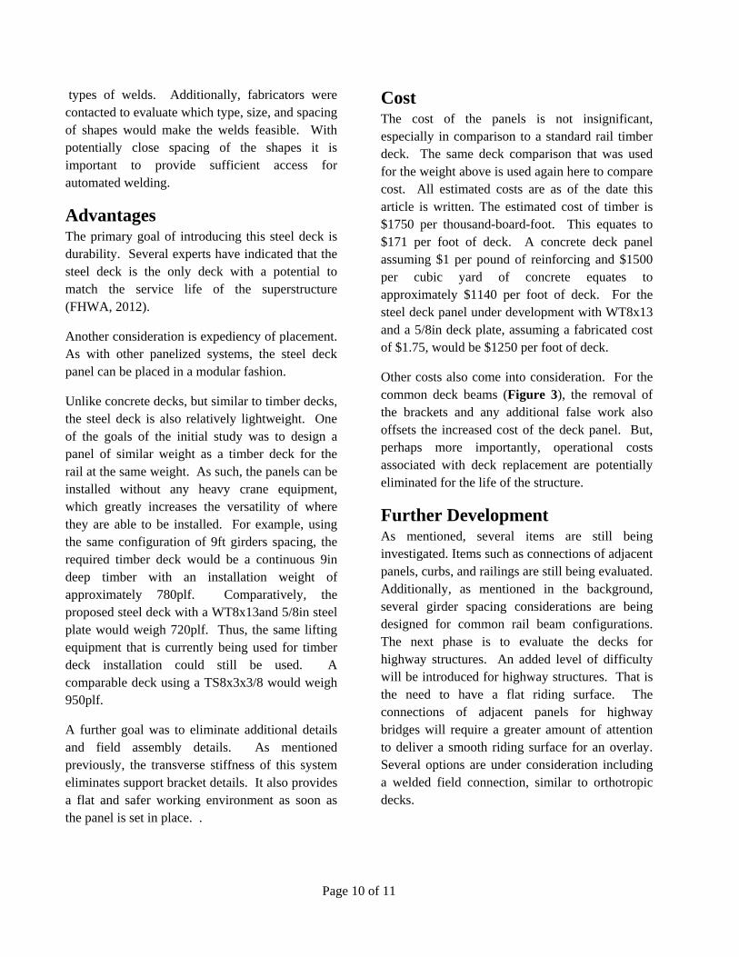
Advantages The primary goal of introducing this steel deck is durability. Several experts have indicated that the steel deck is the only deck with a potential to match the service life of the superstructure (FHWA, 2012).
Another consideration is expediency of placement. As with other panelized systems, the steel deck panel can be placed in a modular fashion.
Unlike concrete decks, but similar to timber decks, the steel deck is also relatively lightweight. One of the goals of the initial study was to design a panel of similar weight as a timber deck for the rail at the same weight. As such, the panels can be installed without any heavy crane equipment, which greatly increases the versatility of where they are able to be installed. For example, using the same configuration of 9ft girders spacing, the required timber deck would be a continuous 9in deep timber with an installation weight of approximately 780plf. Comparatively, the proposed steel deck with a WT8x13and 5/8in steel plate would weigh 720plf. Thus, the same lifting equipment that is currently being used for timber deck installation could still be used. A comparable deck using a TS8x3x3/8 would weigh 950plf.
A further goal was to eliminate additional details and field assembly details. As mentioned previously, the transverse stiffness of this system eliminates support bracket details. It also provides a flat and safer working environment as soon as the panel is set in place. .
Cost The cost of the panels is not insignificant, especially in comparison to a standard rail timber deck. The same deck comparison that was used for the weight above is used again here to compare cost. All estimated costs are as of the date this article is written. The estimated cost of timber is $1750 per thousand-board-foot. This equates to $171 per foot of deck. A concrete deck panel assuming $1 per pound of reinforcing and $1500 per cubic yard of concrete equates to approximately $1140 per foot of deck. For the steel deck panel under development with WT8x13 and a 5/8in deck plate, assuming a fabricated cost of $1.75, would be $1250 per foot of deck.
Other costs also come into consideration. For the common deck beams (Figure 3), the removal of the brackets and any additional false work also offsets the increased cost of the deck panel. But, perhaps more importantly, operational costs associated with deck replacement are potentially eliminated for the life of the structure.
Further Development As mentioned, several items are still being investigated. Items such as connections of adjacent panels, curbs, and railings are still being evaluated. Additionally, as mentioned in the background, several girder spacing considerations are being designed for common rail beam configurations. The next phase is to evaluate the decks for highway structures. An added level of difficulty will be introduced for highway structures. That is the need to have a flat riding surface. The connections of adjacent panels for highway bridges will require a greater amount of attention to deliver a smooth riding surface for an overlay. Several options are under consideration including a welded field connection, similar to orthotropic decks.
Page 11 of 11
References AREMA Manual to Railway Engineering, Vol. 2, Chapter 15 Steel Structures (2013), American Railway Engineering and Maintenance-of-Way Association, Lanham MD
AASHTO LRFD Bridge Design specifications (2012), American Association of State and highway Transportation Officials, Washington DC
Railroad Engineering, W.W. Hay, John Wiley and Sons Inc., New York, NY (1982)
FHWA Manual for Design, Construction, and Maintenance of Orthotropic Steel Deck Bridges (2012), US Department of Transportation Federal Highway Administration, Office of Bridge Technology, Washington DC