development of high performance copper alloy chill vent
TRANSCRIPT

Development of High Performance Copper Alloy
Chill Vent for High Pressure Die Casting
Duoc T Phan, Syed H Masood*, Syed H Riza, and Harsh Modi Department of Mechanical and Product Design Engineering, Swinburne University of Technology, Hawthorn,
Melbourne, Australia
*Email: [email protected]
Abstract— In High Pressure Die Casting (HDPC) process,
chill vents are used to allow residual air and gases to
exhaust out from the mould cavity. The objective of this
paper is to design and develop a high-performance chill vent
for high pressure die casting using a new type of copper
alloy material, which has high strength and high thermal
conductivity, compared to conventional tool steel. Finite
element analysis is applied to develop a numerical heat
transfer model for chill vent and validated by experimental
results. The model is used to compare the performance of
copper alloy chill vent with conventional steel chill vent. It
was found that the change in the chill vent material had a
significant improvement on the cooling time, cooling rate as
well as on the internal die temperature distribution.
Results show that the copper chill vent increases the cooling
efficiency of the solidifying aluminium alloy by about 158%
compared to the conventional steel chill vents. It is
concluded that the use of high strength copper alloy chill
vents will enhance the efficiency and effectiveness of HPDC
process with rapid heat transfer and faster release of gases,
thus reducing porosity and flashing defects in the parts.
Index Terms—High pressure die casting; Chill vents;
Thermal analysis; Copper alloy; Thermal conductivity;
Cooling rates
I. INTRODUCTION
High Pressures Die Casting (HPDC) is widely used in
the automotive industry to manufacture light weight
metal parts. Several manufacturers are gradually moving
toward increased use of lightweight aluminium alloy
castings such as ADC12 for making components
previously made from steel and cast iron. In high
pressure die casting process, molten metal is injected
under high pressure into a tool steel mould or die cavity
to form products of desirable shape [1,2]. The schematic
diagram of the HPDC process is shown in Fig. 1. Chill
vent is a common method in high pressure die casting to
remove the air from die cavity. Chill vent consists of a
pair of steel metal blocks with a zigzag venting path
typically 0.5 mm of gap provided for air flow as shown in
Fig 1. The system formed on the surfaces of the two
blocks is mounted on the die to permit easy escape of
entrapped air from the cavity [3]. Chill vent helps to
reduce defects like porosity in the castings that can affect
product quality. In the conventional steel chill vents,
Manuscript received July 7, 2019; revised May 15, 2020.
sometimes molten metal is also flushed through the air
venting surfaces which often becomes difficult to prevent
because of low thermal conductivity of steel.
Figure 1. Schematic diagram of a typical HPDC process.
Since the function of a chill vent is to remove the air
and gases from the mould cavity in least amount of time
and to increase the solidification rate of castings, a
material of high strength and high thermal conductivity
would be more appropriate for its manufacture. One such
material is beryllium copper alloy, also known as
MoldMAX, which has not only higher strength than steel,
but also exhibits six times higher thermal conductivity as
compared to steel [4]. Therefore, these properties make
MoldMAX alloy a suitable candidate to replace the
conventional tool steel for manufacturing the chill vents.
This study intends to investigate the performance of
beryllium copper alloys for manufacturing chill vents in
HPDC in comparison to steel vents.
In high pressure die casting, the numerical and finite
element based modelling of solidification process and
undergoing thermal processes can be highly beneficial in
improving the efficiency of the die casting process and
evaluating the possibilities to reduce the cooling time.
There have been several investigations on simulation
studies involving analysis of numerous process
parameters, which are critical for accurate thermal
analysis and reducing defects in the HPDC process.
Rosindale and Davey [5] developed a three-
dimensional numerical model that was used to predict the
943
International Journal of Mechanical Engineering and Robotics Research Vol. 9, No. 7, July 2020
© 2020 Int. J. Mech. Eng. Rob. Resdoi: 10.18178/ijmerr.9.7.943-948

steady state thermal behaviour of the metal injection
system of a hot chamber pressure die casting machine.
The model yields time averaged die and injection system
temperatures and the heat input from localised heating
arrangements, which can be used to identify potential
problem areas and cold spots on the surfaces of the
injection system, die cavity and casting.
Rasgado et al [6] have investigated the establishment
of thermal models for bimetallic copper-alloyed dies
protected with a thermally sprayed steel layer. Both
steady state and transient thermal models were developed
that can predict the time averaged and transient cyclic
thermal behaviour of the new die designs.
Ahmed et al [7] have carried out a mold flow analysis
using Castal simulation software to predict the defects in
the die for the high pressure die casting of an aluminium
alloy heat sink. They have shown that design changes in
gate and runner system and increasing the over flow area
helped in achieving zero porosity in small dies, where
chill vents could not be included.
Kwon and Kwon [8] have used the simulation software
(AnyCasting) to optimize the gate and runner design of
an automobile part. Through modification of the gate and
runner system and the configuration of overflows,
internal porosities caused by air entrapments were
predicted and reduced by a significant ratio.
Wenbo Yu et al [9] have studied the interfacial heat
transfer behaviour at the metal/shot sleeve interface in the
high pressure die casting (HPDC) process of AZ91D
aluminium alloy. The effect of different slow shot speed
on the interfacial heat transfer behaviour were
investigated to optimise the conditions to reduce the
externally solidified crystals or cold flake defects in the
casting.
Jeong et al [10] have applied the MAGMAsoft casting
simulation program to predict and prevent the possibility
of casting defects that may occur in the filling process
and solidification process for the high pressure die
casting for an aluminium clutch housing product.
Although several factors have been studied using
simulation methods, little attention is paid to the design
and development of chill vents and air venting problem in
a HDPC process. This investigation aims to fill this
research gap and investigate the performance of a new
chill vent configuration using MoldMAX instead of
conventional tool steel. MoldMAX is a beryllium copper
alloy, a material of high strength and higher thermal
conductivity than steel. This alloy also provides the
advantage of forming a preventive oxide film on the
surface of chill vent, while in contrast the tool steel chill
vents chemically react with molten aluminium and
produce sticking depositions. Therefore, MoldMAX
material can maintain several times larger vent gap than
steel during the mould operating life. This study
describes the process of developing a numerical heat
transfer model for the tool steel chill vent and then
compares it with the simulation results of beryllium-
copper alloy chill vent. The simulation model has been
validated with the real-time experimental test of
aluminium alloy casting performed on a commercial 800
tonne die casting machine.
II. HEAT TRANSFER MODEL
Fig. 2 shows the 3D computer aided design (CAD)
model of the chill vent used in this study. The chill vent
with zigzag surfaces was modelled in a commercial CAD
system. Then, it was imported and meshed using the
general-purpose finite element ANSYS® Workbench
package for the heat transfer modelling and thermal
analysis. The chill vent contains a fountain type single
cooling waterline in each half. The flashing aluminium
part was also created and meshed in order to use for
applying the thermal loads, heat generation rate and heat
flux.
Figure 2. A CAD model of the chill vent used in HPDC
A. Boundary Conditions
After metal injection in the mold, heat energy is
transferred from the melt to the chill vent. Heat is lost by
convection to water in the cooling channels in the chill
vent blocks and to air from the top surfaces. Heat is also
extracted by conduction from the surfaces between the
chill vent and die blocks. In brief, the heat transfer
between a flashing casting and chill vent is governed by
conduction, whereas heat is removed from the system
principally by convection from the cooling system and
the top surfaces of the chill vent blocks. The original
material used for making the chill vent and the mold was
hot work tool steel (H13) with the initial temperature
considered for analysis was 73.8oC. The casting material
was aluminium alloy type – ADC12, which was prepared
in an electric resistance furnace with the pouring
temperature at about 615°C. At the time of the ejection,
after 15.9s, the average temperature at the casting and
chill vent surfaces are the same, 94oC. It is noted that all
of the values used as initial conditions were obtained
from experimental test of aluminium alloy casting on a
commercial 800 tonne die casting machine.
A convection load that occurs between the chill vent
and the cooling system in the chill vent blocks was
applied on the surfaces of the cooling channel to account
for heat extraction. Water at 20oC was used as the cooling
944
International Journal of Mechanical Engineering and Robotics Research Vol. 9, No. 7, July 2020
© 2020 Int. J. Mech. Eng. Rob. Res

medium in the chill vent cooling channels. For a circular
tube of uniform wall temperature, the heat transfer
coefficient can be calculated using the following equation
based on Dittus-Boetler correlation for forced convective
heat transfer [11].
where:
hwater = Heat transfer coefficient in the cooling system
(W/m2C)
Re and Pr = Reynolds and Prandtl number
kwater = Thermal conductivity of water at 20
oC (W/m
oC)
Dwater = Cooling channel diameter (mm)
Using the appropriate values of Prandtl Number and
Reynolds Number, the thermal properties of water, and
the diameter of the cooling channel in the vent, the heat
transfer coefficient hwater at the bulk fluid (water)
temperature of 20oC was calculated to be 1253 W/m
2oC.
Besides that, the ambient air temperature and heat
transfer coefficient with air at the top chill vent surface
were assumed to be 30oC and 10 W/m
2oC respectively.
The material properties for the ADC12 aluminium alloy
were obtained from MatWeb material property data [12].
There are several parameters that influence the
magnitude and variation of casting temperature. After
analyzing many published experimental results, it is
noted that when the casting temperature is plotted against
the casting time, the variation follows an exponential
profile. Consequently, the temperature at the aluminium
casting surface Tcasting was assumed to be a function of
time with an exponential behaviour. Considering the
boundary conditions, the final expression, which was
derived for estimating the cooling time curve for flashing
aluminium casting part is given by the following equation:
Tcasting=Toe
t
tejectionln
Tejection
To
where:
Tcasting Temperature at the casting surface (oC)
To Injection temperature (oC)
Tejection Ejection temperature (94oC)
t Elapsed time (s)
tejection Ejection time (15.9s)
By using this function and the boundary conditions, the
cooling curve of flashing aluminium part was calculated.
These values were then used to calculate the heat
generation rate as well as heat flux for the FEA heat
transfer model of the chill vent. It is noted that all of the
values used as boundary conditions were obtained from
experimental test on a high pressure die casting machine
for ADC12 aluminium alloy. The pouring temperature
was To = 615oC and the temperature at the ejection time
tejection = 15.9 second was Tejection = 94oC.
As the gap thickness between two steel chill vent
blocks is much smaller than the other two dimensions, the
heat of fusion of aluminium can be assumed to flow
uniformly in the x and y directions, while the z-direction
can be taken as perpendicular to the flow field. Therefore,
the following one-dimensional heat conduction equation
can be used to calculate the amount of heat released Q
(W/m3), and the total heat flux q (W/m
2) [13]:
where:
3)
2)
ρ Flashing aluminium density (Kg/m3)
Cp Flashing aluminium specific heat (J/KgoC)
From all the available and calculated parameters, the
heat generation rate (Q) and the heat flux (q) released
during cooling and melting of ADC12 alloy to the
ejection temperature (94oC) are calculated and are shown
in Fig. 3. These thermal loads variations were then used
in the ANSYS® simulation program to calculate the
temperature distribution and cooling time.
B. Running and Validating the Model
The model took approximately two hours to simulate
for one casting cycle using the current version of
ANSYS® Workbench. A more refined mesh was also
run to assess model sensitivity to mesh density. However,
based on experience, reducing the mesh size beyond a
certain threshold value causes negligible improvement in
accuracy of results. In addition, increasing the number of
sub-steps to higher values may cause the solution to
converge, but this will add greatly to the computational
time and computer hardware requirements.
Figure 3.
Heat generation rate and Heat flux values used for thermal analysis.
The simulated results indicate that the current mesh
and the number of sub-steps (201 nodes) are adequate to
compare with the experimental results. Fig. 4 shows the
maximum and minimum surface temperatures for the
moving tool steel chill vent block to be 98.67oC and
67.15oC respectively, as obtained from simulation. These
temperature values were then compared with the real-
time experimental results in order to validate the FEA
heat transfer model.
945
International Journal of Mechanical Engineering and Robotics Research Vol. 9, No. 7, July 2020
© 2020 Int. J. Mech. Eng. Rob. Res
m Flashing aluminium mass (Kg)
V Flashing volume (m
A Flashing surface area (m
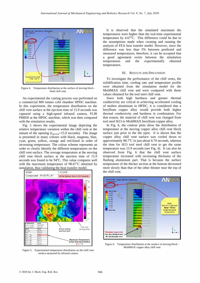
Figure 4. Temperature distribution at the surface of moving block - Steel chill vent.
An experimental die casting process was performed on
a commercial 800 tonnes cold chamber HPDC machine.
In this experiment, the temperature distribution on the
chill vent surface at the ejection time of 15.9 seconds was
captured using a high-speed infrared camera, FLIR
PM850 at the HPDC machine, which was then compared
with the simulation results.
Fig. 5 shows the experimental image depicting the
relative temperature variation within the chill vent at the
instant of die opening (tejection=15.9 seconds). The image
is presented in many colours with black, magenta, blue,
cyan, green, yellow, orange and red-listed in order of
increasing temperature. The colour scheme represents an
order to clearly identify the different temperatures on the
chill vent surface. The average temperature at the moving
chill vent block surface at the ejection time of 15.9
seconds was found to be 94oC. This value compares well
with the maximum temperature of 98.67oC obtained by
simulation, thus validating the heat transfer model.
Figure 5. Experimental temperature distribution on the chill vent surface measured by infrared camera
It is observed that the simulated maximum die
temperatures were higher than the real-time experimental
temperature by 4.67oC. This difference could be due to
the assumptions made when creating and running the
analysis of FEA heat transfer model. However, since the
difference was less than 5% between predicted and
measured temperatures, therefore, it can be accepted that
a good agreement exists between the simulation
temperatures and the experimentally obtained
temperatures.
III. RESULTS AND DISCUSSION
To investigate the performance of the chill vents, the
solidification time, cooling rate and temperature profile
were obtained from the simulation model for the
MoldMAX chill vent and were compared with those
values obtained for the tool steel chill vent.
Since both high hardness and greater thermal
conductivity are critical in achieving accelerated cooling
of molten aluminium in HPDC, it is considered that a
beryllium copper alloy would provide both higher
thermal conductivity and hardness in combination. For
that reason, the material of chill vent was changed from
tool steel H13 to MoldMAX beryllium copper alloy.
In Fig. 6, the contour plots show the distribution of
temperature at the moving copper alloy chill vent block
surface just prior to the die open. It is shown that the
copper alloy chill vent surface was cooled down to
approximately 98.7oC in just about 6.70 seconds, whereas
the time for H13 tool steel chill vent to get the same
temperature was 15.9 seconds (see Fig. 4). It can also be
observed from Fig. 6 that the chill vent surface
temperature increased with increasing thickness of the
flashing aluminium part. That is because the surface
temperature of the thicker section at the bottom decreased
more slowly than that of the other thinner near the top of
the chill vent.
Figure 6.
Temperature distribution at the surface of
moving block -
MoldMAX
copper alloy chill vent
946
International Journal of Mechanical Engineering and Robotics Research Vol. 9, No. 7, July 2020
© 2020 Int. J. Mech. Eng. Rob. Res

Figure 7. Comparison of cooling time curves during casting process using the steel and copper chill vents.
Fig. 7 shows the typical thermal histories at the
MoldMAX and H13 chill vent surface during
solidification of the ADC12 alloy.
It is noted that the chill vent temperature rose quickly
after each shot until reaching its peak value of about
108.7oC and 124.1
oC respectively, after which the
temperature dropped until the next shot. In general, it can
be seen that an increase in thermal conductivity from 27
W/moC for tool steel to 155 W/m
oC for copper material
significantly reduces the peak temperatures of the chill
vent surface. Once again, the time taken for the steel chill
vent surface to cool from pouring temperature of melting
aluminium, 615oC, to the ejection temperature, 98.7
oC,
was 15.90 seconds, whereas in the beryllium copper alloy
MoldMAX chill vent, it took only about 6.70 seconds to
cool to a similar temperature
The comparison of cooling rate and cooling efficiency
of both tool steel and copper chill vents shows that the
cooling rates to cool the flashing aluminium part from
pouring temperature to ejection temperature are 32.5oC/s
and 77oC/s for steel and copper alloy chill vents
respectively. Thus, it is noted that the chill vent of
MoldMAX material type increases the cooling efficiency
by about 158%. Future work should consider the
influence of other parameters such as pouring
temperature, superheat, air gap formation, injection
velocity, and pressure intensification.
IV. CONCLUSIONS
In this investigation, the Finite Element Analysis was
used to develop a heat transfer simulation model for the
tool steel chill vent used in HPDC and was validated by
experimental measurements of the actual HDPC of
aluminium alloy. The vaidated heat trasnfer model was
then used to study the performance of beryllium copper
alloy chill vent in comparison to steel chill vent. The
results indicated that the use of high strength, high
thermally conductive copper alloy as chill vent material
had a significant improvement on the cooling time,
cooling rate as well as the internal die temperature
distribution. It was found that the time taken for the steel
chill vent surface to cool from pouring temperature of
melting aluminium to the ejection temperature was 15.9
seconds, whereas in the beryllium copper alloy
MoldMAX material condition, it took only about 6.70
seconds to cool to a similar temperature. The calculated
cooling rates to cool the flashing aluminium part from
pouring temperature to ejection temperature for the steel
chill vent and copper alloy chill vent were found to be
32.5oC/s and 77
oC/s respectively, thus giving an increase
of 158% in cooling efficiency for the copper alloy chill
vent. The study has established that using a high strength
copper alloy for chill vent improves the performance and
the chilling ability of the permanent mold casting dies in
High Pressure Die Casting of aluminium.
CONFLICT OF INTEREST
The authors declare no conflict of interest.
AUTHOR CONTRIBUTIONS
DT Phan conducted the research and wrote the first
draft of paper. SH Masood supervised the project and
checked the data. SH Riza and H Modi revised and
improved the paper with more literature review. All
authors had approved the final version.
ACKNOWLEDGEMENTS
The authors would like to gratefully acknowledge the
technical support of Mr M. Khalid Imran, Mr. Brian
Dempster, and Mr. Warren Gooch at Swinburne
University during this investigation.
REFERENCES
[1] A Kaye, A Street. Die Casting Metallurgy. Butterworth and Co Ltd., 1982
947
International Journal of Mechanical Engineering and Robotics Research Vol. 9, No. 7, July 2020
© 2020 Int. J. Mech. Eng. Rob. Res

[2] F. Bonollo, N. Gramegna, and G. Timelli, “High-pressure die-
casting: contradictions and challenges,” The Minerals, Metals &
Materials Society, JOM, vol. 67, no. 5, pp. 901-908, 2015.
[3] L. H. Wang. “Mathematical modelling of air evacuation in die casting process via CASTvac and other venting devices,” Int
Journal of Cast Metals Research, vol. 20 pp. 191- 197, 2007.
[4] MoldMAX HH Material Property Data, Materion Performance Alloys, Materion Corporation 2017.
[5] I. Rosindale and K. Davey, “Steady state thermal model for the
hot chamber injection system in the pressure die casting process,” Journal of Materials Processing Technology, vol. 82, no. 1, pp.
27-45, 1998.
[6] M. T. A. Rasgado, “Bi-metallic dies for rapid die casting,” Journal of Materials Processing Technology vol. 175, pp. 109–
116, 2006.
[7] S. R. Ahmed, K. D. Devi, and S. V. S. Himathejeswini, “Design & analysis of heat sink high-pressure die casting component,”
International Journal of Current Engineering and Technology,
2016 [8] H. J. Kwon, H. K. Kwon, “Computer Aided Engineering (CAE)
simulation for the design optimization of gate system on high
pressure die casting (HPDC) process,” Robotics and Computer–Integrated Manufacturing vol. 55 pp. 147–153, 2018.
[9] W. B. Yu, Y. Y. Cao, X. B. Li et al, “Determination of interfacial
heat transfer behavior at the metal/shot sleeve of high pressure die casting process of AZ91D alloy,” Journal of Materials
Science & Technology vol. 33 pp. 52–58, 2017
[10] S. I. Jeong, C. K. Jin, H. Y. Seo et al, “Mould design for clutch housing parts using a casting simulation of high pressure die
casting,” International Journal Of Precision Engineering And
Manufacturing, vol. 17, no. 11, pp. 1523-1531, 2016 [11] R. W. R. W. Jeppson, Analysis of Flow in Pipe Networks,
Butterworth Publications, 1976
[12] MatWeb Material Property Data, Aluminum ADC12 Die Casting Alloy, Automation Creations, Inc 2009.
[13] K. N. Prabhu, “Casting/mold thermal contact heat transfer during
solidification of Al-Cu-Si alloy (LM 21) plates in thick and thin molds,” Journal of Materials Engineering and Performance,
ASM International vol. 14, no. 5, pp. 604-609, 2005.
Copyright © 2020
by the authors. This is an open access article
distributed under the Creative Commons Attribution License (CC BY-
NC-ND 4.0), which permits use, distribution and reproduction in any
medium, provided that the article is properly cited, the use is non-
commercial and no modifications or adaptations are made.
Mr Duoc Thanh Phan
completed his Master of Engineering (Honours) in Advanced Manufacturing Technology at Swinburne University of
Technology, Melbourne, Australia. His research interests are High
Pressure Die Casting, Numerical Simulation,
and Cold Spray Additive Manufacturing.
Prof Syed H Masood
is a Professor of Mechanical and Manufacturing Engineering at
Swinburne University of Technology, Melbourne,
Australia. His current research interests are in Additive Manufacturing, Selective Laser Melting,
and other Advanced Manufacturing Processes.
Dr Syed H Riza
is a teaching staff at Department
of Mechanical and
Product Design
Engineering at Swinburne University of Technology, Melbourne, Australia. His current research interests are in Additive
Manufacturing, Direct Metal
Deposition, Robotics and Material
Characterisation.
Mr Harsh Modi
is a Master of Professional Engineering student at
Swinburne University of Technology, Melbourne, Australia. His current research interests are in Advanced Manufacturing, 3D Printing
and Mechanical Design.
948
International Journal of Mechanical Engineering and Robotics Research Vol. 9, No. 7, July 2020
© 2020 Int. J. Mech. Eng. Rob. Res