development of remote control robot car using infrared …
TRANSCRIPT

MIE2019
Symposium on Manufacturing and Industrial Engineering
DEVELOPMENT OF REMOTE CONTROL ROBOT CAR USING INFRARED
SENSOR AND PWM
Cheah Kai Bin, Ahmad Afif Adli and Wan Rahiman1
School of Electrical and Electronic Engineering
Universiti Sains Malaysia, Engineering Campus
Pulau Pinang, Malaysia.
Corresponding Author’s Email: [email protected]
ABSTRACT: In today's modern world, an autonomous driving system is capability of a vehicle or
a robot moving without control with a promising technological concept. However, at the same
time, manual control system are still playing a significant role in robotic field. The final goal of the
project is to create a robot car system that utilizes both manual and auto control through usage of
the infrared (IR) sensor. The infrared sensors enable robot to be control through manually or
through obstacle while making the project low-cost and affordable. This technical report
demonstrates the development of prototype of the IR sensor controlled robot car. The main
objective of this design is to focus on versatility, durability, simplicity and improvised operations.
KEYWORDS: FPGA, Infrared (IR) sensor, Pulse Width Modulation (PWM)
1.0 INTR ODU CTION
An infrared (IR) sensor is an electronic instrument that is used to sense certain characteristics of its
surroundings and there are many applications by means of IR device. It does this by either emitting
or detecting infrared radiation. Infrared sensors are also capable of measuring the heat being
emitted by an object and detecting motion. Buldu (2016) optimizes the use of IR transmitter to
measure the pulse rate of the drive while driving the vehicle.
Infrared technology is not only found in the industry, but also in every-day life. Televisions, for
example, use an infrared detector to interpret the signals sent from a remote control. Passive
Infrared sensors are used for motion detection systems, and LDR sensors are used for outdoor
lighting systems. The key benefits of infrared sensors include their low power requirements, their
simple circuitry and their portable features.
Flynn A. M. (1988) has studied navigation system that utilize IR implementation for motion.
Multiple sensors can be used on a mobile robot so that it can perceive its environment with better
accuracy than if either sensor were used alone. Sonar and infrared sensors are used here in a
complementary fashion, where the advantages of one compensate for the disadvantages of the
other. The robot then combines the information from the two sensors to build a more accurate map.
Another representation, a modified version of the curvature primal sketch, is extracted from this
perceived workspace and is used as the input to two path planning programs: one based on
configuration space and one based on a generalized cone formulation of free space.

MIE2019
Symposium on Manufacturing and Industrial Engineering
2.0 PROJECT DEVELOPMENT
The purpose of this project is to build and develop a navigation system that takes input from IR
sensors, using them to help the vehicle move forward and turn based on the inputs given. Overall
process can be divided into 3 parts; (a) Picking up of surrounding signals through sensors, (b)
Signals sent to central processor. Processor read the signals, computes the direction for the car, and
send out the signals and (c) Wheels of robot receive the signals and move.
The main objectives are developing of a system that enables auto and manual control, in which
auto mode enable detection and passing of obstacles in front, while manual mode ensure the car to
follow the direction of motion from user.
The project was taking a concept introduced by Murat A. J. et al. (2014) to compare the physical
and mathematical results conducted in accordance with the properties of radio controlled car with
the results that come out from the simulation in FPGA platform. These results will depend on the
physical properties of radio-controlled car and the properties of the environment. In order to have
successful result, which leads to proper operation (desired movement) of a radio controlled, the
car must choose the appropriate electrical component and the suitable electrical component for a
safe movement. The project were following Sedra A. S. et al. (2004) and Gray P. R. (2009) on how
to analyze and design electronic circuits.
3.0 MECHANISM AND PROJECT DEVELOPMENT
3.1 Components and functions
A few components are needed for the project. Two Direct Current (DC) motors are used as wheels,
and L293D IC to act as the motor driver for both of the dc motors. For the computing unit /
programmable integrated circuit (IC), in this project, Field Programmable Gate Array (FPGA) name
Altera Cyclone IV E (ce115f29c7n) by Intel was used. Software use to program the FPGA is Quartus
IV 12.1 edition.
Firstly, the IR sensors will pick up motion or object from three different direction (front, left and
right). If a signal is detected, IR sensor will send it to FPGA for analysis, and output is given based
on mode that has been chosen. For auto mode, the robot car will move to the right if left IR get
reading, left if right IR give reading, and stop if straight path is blocked. For manual mode user can
control the direction of car by blocking the IR sensor, (left if left sensor have reading, right if right
and so on). Controlling of both left and right motor were done by using the L293D IC that act as
motor driver.
3.2 Block diagram
Figure 1: Pin of IC L293D
MIE2019
Symposium on Manufacturing and Industrial Engineering
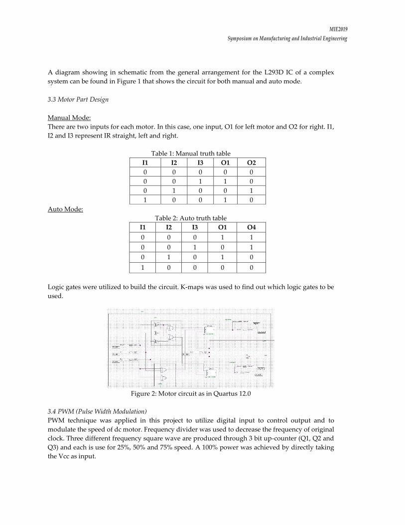
A diagram showing in schematic from the general arrangement for the L293D IC of a complex
system can be found in Figure 1 that shows the circuit for both manual and auto mode.
3.3 Motor Part Design
Manual Mode:
There are two inputs for each motor. In this case, one input, O1 for left motor and O2 for right. I1,
I2 and I3 represent IR straight, left and right.
Table 1: Manual truth table
I1 I2 I3 O1 O2
0 0 0 0 0
0 0 1 1 0
0 1 0 0 1
1 0 0 1 0
Auto Mode:
Table 2: Auto truth table
I1 I2 I3 O1 O4
0 0 0 1 1
0 0 1 0 1
0 1 0 1 0
1 0 0 0 0
Logic gates were utilized to build the circuit. K-maps was used to find out which logic gates to be
used.
Figure 2: Motor circuit as in Quartus 12.0
3.4 PWM (Pulse Width Modulation)
PWM technique was applied in this project to utilize digital input to control output and to
modulate the speed of dc motor. Frequency divider was used to decrease the frequency of original
clock. Three different frequency square wave are produced through 3 bit up-counter (Q1, Q2 and
Q3) and each is use for 25%, 50% and 75% speed. A 100% power was achieved by directly taking
the Vcc as input.

MIE2019
Symposium on Manufacturing and Industrial Engineering
Table 3: Truth table for T flip-flop
Qi Qi+ T
0 0 0
0 1 1
1 0 1
1 1 0
Truth table for Counter with output as mention is build.
Table 4: Truth Table for counter
Q2 Q1 Q0 Q2+ Q1+ Q0+ T2 T1 T0
0 0 0 1 0 0 1 0 0
1 0 0 1 1 0 0 1 0
1 1 0 1 1 1 0 0 1
1 1 1 0 0 0 1 1 1
Figure 3: Counter circuit.
In Figure 3, four and gates and one or gate were used as switch to choose between suitable speed.
3.5 Display
7-segment display was used on FPGA as display to monitor activities on the system. There are two
types of displays were set up; mode display and speed display.
3.5.1 Mode display
The truth table and k-maps were utilized in order to obtain all needed output and build the circuit
through or gate.
MIE2019
Symposium on Manufacturing and Industrial Engineering
Figure 4: Circuit for mode display.
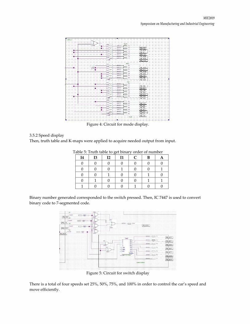
3.5.2 Speed display
Then, truth table and K-maps were applied to acquire needed output from input.
Table 5: Truth table to get binary order of number
I4 I3 I2 I1 C B A
0 0 0 0 0 0 0
0 0 0 1 0 0 1
0 0 1 0 0 1 0
0 1 0 0 0 1 1
1 0 0 0 1 0 0
Binary number generated corresponded to the switch pressed. Then, IC 7447 is used to convert
binary code to 7-segmented code.
Figure 5: Circuit for switch display
There is a total of four speeds set 25%, 50%, 75%, and 100% in order to control the car’s speed and
move efficiently.

MIE2019
Symposium on Manufacturing and Industrial Engineering
4.0 CONCLUSION
The utilization of the IR sensors in the robot car is suitable to be used for object/motion detection
when navigating around an environment. Provided that users properly control the IR sensors, the
robot car will successfully conduct its course of driving without any difficulty. This solution is
economically viable, due to the simple construction method and the use of affordable materials
and components. Several further improvement can be done, including implementation of PMW
system that enable speed changing of wheels into turning mechanism to increase its mobility and
flexibility. Further modification can be done so that the robot not only can sense the obstacles, while
also can avoid them and even move them from the path. This may help in the development of low-
cost household robot or life-saving robots during disaster.
5.0 ACKNOWLEDGEMENT
This project was supported by the Universiti Sains Malaysia under the Bridging Grant
304.PELECT.6316121. We would like to thanks the university for allowing us to use the FPGA
Laboratory at the School of Electrical and Electronic Engineering, Universiti Sains Malaysia to
complete the project.
6.0 REFERENCES
Buldu A. & Yildiz K. (2016, July). A Circuit Design by Using an Infrared Sensor Transmitter and
Pic16f628 to Measure the Pulse Rate of the Driver. Measurement and Control, 49(6), 191-196
Flynn A. M. (1988). Combining Sonar and Infrared Sensors for Mobile Robot Navigation.
International Journal of Robotics Research, 5-14
Gray P. R. (2009). Analysis and Design of Analog Integrated Circuit. Fourth Edition. Wiley
Murati A. J., Fountas N.A., Vaxevanidis N. M. & Shabani E. (2016). Design and Study of Special
Radio Controlled Car. International Conference Research and Development in Mechanical Industry
Sedra A. S., Smith K. C. & Chandorkar A. N. (2004). Microelectronic Circuits Theory and Application.
Fifth Edition International Edition. Oxford University Press