devicenet configuration terminal user...
TRANSCRIPT
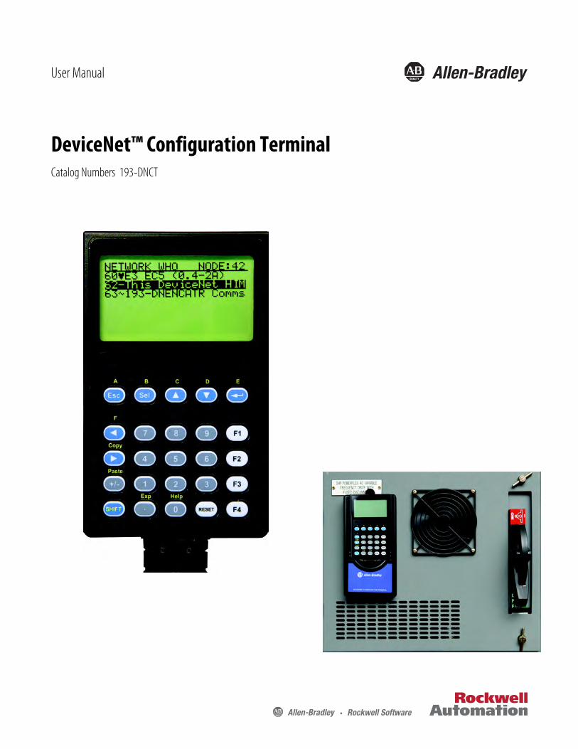
DeviceNet™ Configuration TerminalCatalog Numbers 193-DNCT
User Manual

™ Configuration Terminal
Important User Information
Because of the variety of uses for the products described in this publication, those responsible for the application and use of this control equipment must satisfy themselves that all necessary steps have been taken to assure that each application and use meets all performance and safety requirements, including any applicable laws, regulations, codes and standards.
The illustrations, charts, sample programs and layout examples shown in this guide are intended solely for purposes of example. Since there are many variables and requirements associated with any particular installation, Rockwell Automation does not assume responsibility or liability (to include intellectual property liability) for actual use based upon the examples shown in this publication.
Allen-Bradley publication SGI-1.1, Safety Guidelines for the Application, Installation and Maintenance of Solid-State Control (available from your local Allen-Bradley distributor), describes some important differences between solid-state equipment and electromechanical devices that should be taken into consideration when applying products such as those described in this publication.
Reproduction of the contents of this copyrighted publication, in whole or part, without written permission of Rockwell Automation, is prohibited.
Throughout this manual we use notes to make you aware of safety considerations:
Attention statements help you to:• identify a hazard• avoid a hazard• recognize the consequences
European Communities (EC) Directive Compliance
If this product has the CE mark, it is approved for installation within the European Union and EEA regions. It has been designed and tested to meet the following directives.
• EMC Directive• This product is tested per EN61000-6-4:2001 and EN61000-6-2:2005.
Allen-Bradley is a trademark of Rockwell Automation. DeviceNet™ is a trademark of the Open DeviceNet™ Vendors Association (ODVA). All other trademarks and/or registered trademarks are the property of their respective owners.
ATTENTION: Identifies information about practices or circumstances that can lead to personal injury or death, property damage or economic loss
IMPORTANT Identifies information that is critical for successful application and understanding of the product.
Rockwell Automation Publication 193-UM009B-EN-P - February 2013 iii

Manual Objectives
The purpose of this manual is to provide you with the information necessary to apply the DeviceNet™ Configuration Terminal. Described in this manual are methods for installing, configuring, and troubleshooting the DeviceNet™ Configuration Terminal.
Who Should Use This Manual
This manual is intended for qualified personnel responsible for setting up and servicing DeviceNet™ devices. You must have previous experience with and a basic understanding of communications terminology, configuration procedures, required equipment, and safety precautions.
You should understand DeviceNet™ network operations, including how devices operate on the network.
Vocabulary
In this manual we refer to the:
Bulletin 193 DeviceNet™ Configuration Terminal as 193-DNCT, DNCT, terminal, Configuration Terminal, or HIM (Human Interface Module)
Programmable Logic Controller as a Programmable Controller, PLC controller, SLC controller, ControlLogix Controller, or PLC
DeviceNet™ as DNet or DNET
Reference Manuals
DeviceNet™ Media Design and Installation Guide• Publication DNET-UM072_-EN-P
Copies of this and all other reference publications are available at http://www.rockwellautomation.com/literature/.
IMPORTANT Read this manual in its entirety before installing, operating, servicing, or initializing the DeviceNet™
Configuration Terminal.
IMPORTANT Read the DeviceNet™ Media Design and Installation Guide (Publication DNET-UM072_-EN-P)
in its entirety before planning and installing a DeviceNet™ system. If the network is not installed
according to this document, unexpected operation and intermittent failures may occur.
iv Rockwell Automation Publication 193-UM009B-EN-P - February 2013
Important User Information . . . . . . . . . . . . . . . . . . . . . . . . . . . . . . . . . . . . . . . iiiEuropean Communities (EC) Directive Compliance. . . . . . . . . . . . . . . . . iiiManual Objectives . . . . . . . . . . . . . . . . . . . . . . . . . . . . . . . . . . . . . . . . . . . . . . . . ivWho Should Use This Manual . . . . . . . . . . . . . . . . . . . . . . . . . . . . . . . . . . . . . ivVocabulary . . . . . . . . . . . . . . . . . . . . . . . . . . . . . . . . . . . . . . . . . . . . . . . . . . . . . . . ivReference Manuals . . . . . . . . . . . . . . . . . . . . . . . . . . . . . . . . . . . . . . . . . . . . . . . . iv
Chapter 1Product Overview Product Overview . . . . . . . . . . . . . . . . . . . . . . . . . . . . . . . . . . . . . . . . . . . . . . . . . . 5
Bill of Material . . . . . . . . . . . . . . . . . . . . . . . . . . . . . . . . . . . . . . . . . . . . . . . . . . . . . 5Accessories . . . . . . . . . . . . . . . . . . . . . . . . . . . . . . . . . . . . . . . . . . . . . . . . . . . . . . . . 5
Chapter 2Installation and Wiring Installation and Wiring . . . . . . . . . . . . . . . . . . . . . . . . . . . . . . . . . . . . . . . . . . . . . 7
193-CB1 Physical Connections. . . . . . . . . . . . . . . . . . . . . . . . . . . . . . . . . . 7193-CM1 Physical Connections . . . . . . . . . . . . . . . . . . . . . . . . . . . . . . . . . 7193-DNCT-BZ1 Physical Connections . . . . . . . . . . . . . . . . . . . . . . . . . . 8
Powering the 193-DNCT . . . . . . . . . . . . . . . . . . . . . . . . . . . . . . . . . . . . . . . . . . 8
Chapter 3Physical Features Physical Features . . . . . . . . . . . . . . . . . . . . . . . . . . . . . . . . . . . . . . . . . . . . . . . . . . . 9
Communication Port . . . . . . . . . . . . . . . . . . . . . . . . . . . . . . . . . . . . . . . . . . . . . . 9Key Descriptions . . . . . . . . . . . . . . . . . . . . . . . . . . . . . . . . . . . . . . . . . . . . . . . . . 10Shifted Key Descriptions . . . . . . . . . . . . . . . . . . . . . . . . . . . . . . . . . . . . . . . . . 10
Chapter 4Quick Start Powerup . . . . . . . . . . . . . . . . . . . . . . . . . . . . . . . . . . . . . . . . . . . . . . . . . . . . . . . . 11
Terminal Setup . . . . . . . . . . . . . . . . . . . . . . . . . . . . . . . . . . . . . . . . . . . . . . . . . . 12Network Who Screen . . . . . . . . . . . . . . . . . . . . . . . . . . . . . . . . . . . . . . . . . . . . 12Device Choices Menu . . . . . . . . . . . . . . . . . . . . . . . . . . . . . . . . . . . . . . . . . . . . 12Parameter Monitoring and Editing . . . . . . . . . . . . . . . . . . . . . . . . . . . . . . . . 13DeviceNet™ Configuration Terminal Setup Menus. . . . . . . . . . . . . . . . . . 15Port Object And Routing Sub Nets . . . . . . . . . . . . . . . . . . . . . . . . . . . . . . . . 15Who Menu Display . . . . . . . . . . . . . . . . . . . . . . . . . . . . . . . . . . . . . . . . . . . . . . 16
Chapter 5Device Choices Menu Device Choices Menu . . . . . . . . . . . . . . . . . . . . . . . . . . . . . . . . . . . . . . . . . . . . 17
Version Menu . . . . . . . . . . . . . . . . . . . . . . . . . . . . . . . . . . . . . . . . . . . . . . . . . . . 17Standard Device Status Menu . . . . . . . . . . . . . . . . . . . . . . . . . . . . . . . . . . . . . 18Fault/Warning Choice Menu . . . . . . . . . . . . . . . . . . . . . . . . . . . . . . . . . . . . . 18Fault Menu . . . . . . . . . . . . . . . . . . . . . . . . . . . . . . . . . . . . . . . . . . . . . . . . . . . . . . 18Warning Menu . . . . . . . . . . . . . . . . . . . . . . . . . . . . . . . . . . . . . . . . . . . . . . . . . . 19
Rockwell Automation Publication 193-UM009B-EN-P - February 2013 1
Table of Contents
Chapter 6Parameter Choices Menu Parameter Choices Menu . . . . . . . . . . . . . . . . . . . . . . . . . . . . . . . . . . . . . . . . . 21
Groups Screen . . . . . . . . . . . . . . . . . . . . . . . . . . . . . . . . . . . . . . . . . . . . . . . . . . . 21Num List Selection . . . . . . . . . . . . . . . . . . . . . . . . . . . . . . . . . . . . . . . . . . . . . . . 21Parameter Edit Screens. . . . . . . . . . . . . . . . . . . . . . . . . . . . . . . . . . . . . . . . . . . . 22Numeric Parameters . . . . . . . . . . . . . . . . . . . . . . . . . . . . . . . . . . . . . . . . . . . . . . 22Accessing a Different Parameter . . . . . . . . . . . . . . . . . . . . . . . . . . . . . . . . . . . 22Changing a Parameter Value . . . . . . . . . . . . . . . . . . . . . . . . . . . . . . . . . . . . . . 23Enumerated Parameters . . . . . . . . . . . . . . . . . . . . . . . . . . . . . . . . . . . . . . . . . . . 25Floating Point Parameters . . . . . . . . . . . . . . . . . . . . . . . . . . . . . . . . . . . . . . . . . 26Search for Changed Parameters . . . . . . . . . . . . . . . . . . . . . . . . . . . . . . . . . . . . 27Parameter Display-Value Enumerated. . . . . . . . . . . . . . . . . . . . . . . . . . . . . . 28
Chapter 7Copy Cat Menu Copy Cat . . . . . . . . . . . . . . . . . . . . . . . . . . . . . . . . . . . . . . . . . . . . . . . . . . . . . . . . 29
Copy Cat Uploading . . . . . . . . . . . . . . . . . . . . . . . . . . . . . . . . . . . . . . . . . . . . . 29Copy Cat Downloading. . . . . . . . . . . . . . . . . . . . . . . . . . . . . . . . . . . . . . . . . . . 31Copy Cat Downloading and Product Revisions . . . . . . . . . . . . . . . . . . . . . 33Copy Cat Downloading and Product Current Ratings. . . . . . . . . . . . . . . 34Deleting Copy Cat Files. . . . . . . . . . . . . . . . . . . . . . . . . . . . . . . . . . . . . . . . . . . 36Copy Cat Memory . . . . . . . . . . . . . . . . . . . . . . . . . . . . . . . . . . . . . . . . . . . . . . . 36DeviceLogix™ Library 5 Support . . . . . . . . . . . . . . . . . . . . . . . . . . . . . . . . . . . 36
Chapter 8Tools Menu Tools Menu. . . . . . . . . . . . . . . . . . . . . . . . . . . . . . . . . . . . . . . . . . . . . . . . . . . . . . 37
Node Commissioning . . . . . . . . . . . . . . . . . . . . . . . . . . . . . . . . . . . . . . . . . . . . 37Class Instance Attribute Editor . . . . . . . . . . . . . . . . . . . . . . . . . . . . . . . . . . . . 37Graph Setup Screens. . . . . . . . . . . . . . . . . . . . . . . . . . . . . . . . . . . . . . . . . . . . . . 38Graph View Screen . . . . . . . . . . . . . . . . . . . . . . . . . . . . . . . . . . . . . . . . . . . . . . . 40Assembly Consumed/Produced Menu . . . . . . . . . . . . . . . . . . . . . . . . . . . . . 40
Chapter 9Advanced Functions Menu Advanced Functions Menu. . . . . . . . . . . . . . . . . . . . . . . . . . . . . . . . . . . . . . . . 43
Chapter 10HeartBeat Menus . . . . . . . . . . . . . . . . . . . . . . . . . . . . . . . . . . . . . . . . . . . . . . . . 45
Chapter 11I/O Message Monitoring I/O Message Monitoring. . . . . . . . . . . . . . . . . . . . . . . . . . . . . . . . . . . . . . . . . . 47
2 Rockwell Automation Publication 193-UM009B-EN-P - February 2013
Table of Contents
Chapter 12DeviceLogix™ Functionality DeviceLogix™ Functionality . . . . . . . . . . . . . . . . . . . . . . . . . . . . . . . . . . . . . . . 49
DeviceLogix™ Choices Menu . . . . . . . . . . . . . . . . . . . . . . . . . . . . . . . . . . . . . . 49DeviceLogix™ Monitor. . . . . . . . . . . . . . . . . . . . . . . . . . . . . . . . . . . . . . . . . . . . 49
Boolean Gates: . . . . . . . . . . . . . . . . . . . . . . . . . . . . . . . . . . . . . . . . . . . . . . . 50Bistable Latches: RS Latch and SR Latch . . . . . . . . . . . . . . . . . . . . . . . 50Counters: Up Counter and Up/Down Counter . . . . . . . . . . . . . . . . 50Timers: On Delay, Off Delay and Pulse Timer . . . . . . . . . . . . . . . . . . 51Discrete Output Points (DOPs): . . . . . . . . . . . . . . . . . . . . . . . . . . . . . . 51Produced Network Bits (PNBs):. . . . . . . . . . . . . . . . . . . . . . . . . . . . . . . 51
DeviceLogix™ Editor. . . . . . . . . . . . . . . . . . . . . . . . . . . . . . . . . . . . . . . . . . . . . . 51Creating a New Function Block . . . . . . . . . . . . . . . . . . . . . . . . . . . . . . . . . . . 52Function Blocks. . . . . . . . . . . . . . . . . . . . . . . . . . . . . . . . . . . . . . . . . . . . . . . . . . 53Assigning Source Bits to Function Block Inputs . . . . . . . . . . . . . . . . . . . . 53
Chapter 13Discrete I/O Status Discrete I/O Status. . . . . . . . . . . . . . . . . . . . . . . . . . . . . . . . . . . . . . . . . . . . . . . 55
Chapter 14Zone Interlock Protocol (ZIP) Zone Interlock Protocol (ZIP) . . . . . . . . . . . . . . . . . . . . . . . . . . . . . . . . . . . . 57
ZIP Consumed . . . . . . . . . . . . . . . . . . . . . . . . . . . . . . . . . . . . . . . . . . . . . . . . . . 57Mapping Consumed ZIP Data . . . . . . . . . . . . . . . . . . . . . . . . . . . . . . . . . . . . 58ZIP Produced Data. . . . . . . . . . . . . . . . . . . . . . . . . . . . . . . . . . . . . . . . . . . . . . . 61ZIP Data Table Monitor. . . . . . . . . . . . . . . . . . . . . . . . . . . . . . . . . . . . . . . . . . 61
Chapter 15DeviceNet™ Scanner Menu DeviceNet™ Scanner Menu. . . . . . . . . . . . . . . . . . . . . . . . . . . . . . . . . . . . . . . . 63
Scanner Setup. . . . . . . . . . . . . . . . . . . . . . . . . . . . . . . . . . . . . . . . . . . . . . . . . . . . 63AutoScan Function . . . . . . . . . . . . . . . . . . . . . . . . . . . . . . . . . . . . . . . . . . . . . . 64ScanList Screen . . . . . . . . . . . . . . . . . . . . . . . . . . . . . . . . . . . . . . . . . . . . . . . . . . 64Node Activation Screen . . . . . . . . . . . . . . . . . . . . . . . . . . . . . . . . . . . . . . . . . . 64
Chapter 16Terminal Choices Menu Terminal Choices Menu . . . . . . . . . . . . . . . . . . . . . . . . . . . . . . . . . . . . . . . . . . 65
Version Menu . . . . . . . . . . . . . . . . . . . . . . . . . . . . . . . . . . . . . . . . . . . . . . . . . . . 65Offline Connection Set . . . . . . . . . . . . . . . . . . . . . . . . . . . . . . . . . . . . . . . . . . . 65Offline Change Address Screen . . . . . . . . . . . . . . . . . . . . . . . . . . . . . . . . . . . 66DeviceNet™ Error Log . . . . . . . . . . . . . . . . . . . . . . . . . . . . . . . . . . . . . . . . . . . . 67Network Statistics Screen . . . . . . . . . . . . . . . . . . . . . . . . . . . . . . . . . . . . . . . . . 67
Rockwell Automation Publication 193-UM009B-EN-P - February 2013 3
Table of Contents
Chapter 17Terminal Setup Menu Terminal Setup Menu . . . . . . . . . . . . . . . . . . . . . . . . . . . . . . . . . . . . . . . . . . . . 69
Communication Setup Screen (HIM Comm) . . . . . . . . . . . . . . . . . . . . . . 69Password Menu . . . . . . . . . . . . . . . . . . . . . . . . . . . . . . . . . . . . . . . . . . . . . . . . . . 70
Password Setup (Primary) . . . . . . . . . . . . . . . . . . . . . . . . . . . . . . . . . . . . . 71Password Setup (Secondary) . . . . . . . . . . . . . . . . . . . . . . . . . . . . . . . . . . . 71Entering a Password . . . . . . . . . . . . . . . . . . . . . . . . . . . . . . . . . . . . . . . . . . 72Resetting Forgotten Passwords. . . . . . . . . . . . . . . . . . . . . . . . . . . . . . . . . 72
Auto Display. . . . . . . . . . . . . . . . . . . . . . . . . . . . . . . . . . . . . . . . . . . . . . . . . . . . . 72AutoDisplay Setup. . . . . . . . . . . . . . . . . . . . . . . . . . . . . . . . . . . . . . . . . . . . 73AutoDisplay Test . . . . . . . . . . . . . . . . . . . . . . . . . . . . . . . . . . . . . . . . . . . . . 73
Programmable User Function Key Setup . . . . . . . . . . . . . . . . . . . . . . . . . . . 74Function Key Setup Screen. . . . . . . . . . . . . . . . . . . . . . . . . . . . . . . . . . . . . . . . 75 LCD Contrast . . . . . . . . . . . . . . . . . . . . . . . . . . . . . . . . . . . . . . . . . . . . . . . . . . . 75
Chapter 18Copy and Paste Feature Copy and Paste Feature . . . . . . . . . . . . . . . . . . . . . . . . . . . . . . . . . . . . . . . . . . . 77
Chapter 19Menu Help Feature Menu Help Feature. . . . . . . . . . . . . . . . . . . . . . . . . . . . . . . . . . . . . . . . . . . . . . . 79
Chapter 20Specifications . . . . . . . . . . . . . . . . . . . . . . . . . . . . . . . . . . . . . . . . . . . . . . . . . . . . 81
Specifications
Appendix ADeviceNet™ Objects Identity Object. . . . . . . . . . . . . . . . . . . . . . . . . . . . . . . . . . . . . . . . . . . . . . . . . . . 83
Message Router . . . . . . . . . . . . . . . . . . . . . . . . . . . . . . . . . . . . . . . . . . . . . . . . . . 84DeviceNet™ Object . . . . . . . . . . . . . . . . . . . . . . . . . . . . . . . . . . . . . . . . . . . . . . . 84Connection Object . . . . . . . . . . . . . . . . . . . . . . . . . . . . . . . . . . . . . . . . . . . . . . . 85
4 Rockwell Automation Publication 193-UM009B-EN-P - February 2013
Chapter 1
Product Overview
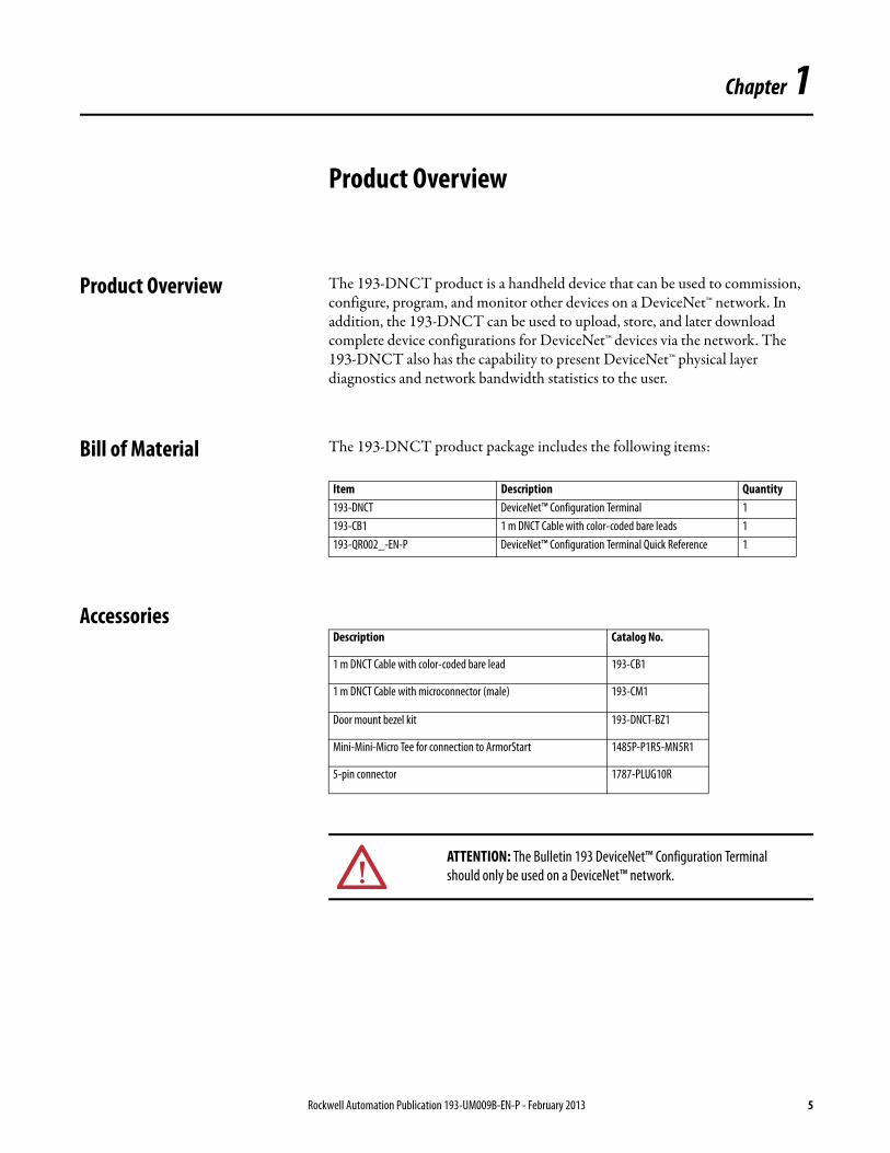
Product Overview The 193-DNCT product is a handheld device that can be used to commission, configure, program, and monitor other devices on a DeviceNet™ network. In addition, the 193-DNCT can be used to upload, store, and later download complete device configurations for DeviceNet™ devices via the network. The 193-DNCT also has the capability to present DeviceNet™ physical layer diagnostics and network bandwidth statistics to the user.
Bill of Material The 193-DNCT product package includes the following items:
Accessories
Item Description Quantity193-DNCT DeviceNet™ Configuration Terminal 1193-CB1 1 m DNCT Cable with color-coded bare leads 1193-QR002_-EN-P DeviceNet™ Configuration Terminal Quick Reference 1
Description Catalog No.
1 m DNCT Cable with color-coded bare lead 193-CB1
1 m DNCT Cable with microconnector (male) 193-CM1
Door mount bezel kit 193-DNCT-BZ1
Mini-Mini-Micro Tee for connection to ArmorStart 1485P-P1R5-MN5R1
5-pin connector 1787-PLUG10R
ATTENTION: The Bulletin 193 DeviceNet™ Configuration Terminal should only be used on a DeviceNet™ network.
Rockwell Automation Publication 193-UM009B-EN-P - February 2013 5

Chapter 1 Product Overview
Notes:
6 Rockwell Automation Publication 193-UM009B-EN-P - February 2013
Chapter 2
Installation and Wiring
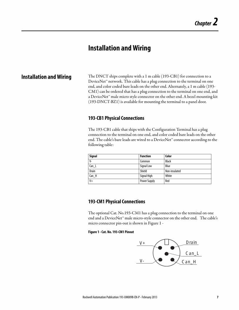
Installation and Wiring The DNCT ships complete with a 1 m cable (193-CB1) for connection to a DeviceNet™ network. This cable has a plug connection to the terminal on one end, and color coded bare leads on the other end. Alternately, a 1 m cable (193-CM1) can be ordered that has a plug connection to the terminal on one end, and a DeviceNet™ male micro style connector on the other end. A bezel mounting kit (193-DNCT-BZ1) is available for mounting the terminal to a panel door.
193-CB1 Physical Connections
The 193-CB1 cable that ships with the Configuration Terminal has a plug connection to the terminal on one end, and color coded bare leads on the other end. The cable’s bare leads are wired to a DeviceNet™ connector according to the following table:
193-CM1 Physical Connections
The optional Cat. No.193-CM1 has a plug connection to the terminal on one end and a DeviceNet™ male micro-style connector on the other end. The cable’s micro connector pin-out is shown in Figure 1 -
Figure 1 - Cat. No. 193-CM1 Pinout
Signal Function ColorV- Common BlackCan_L Signal Low BlueDrain Shield Non-insulatedCan_H Signal High WhiteV+ Power Supply Red
Drain
Can_L
Can_H
V+
V-
Rockwell Automation Publication 193-UM009B-EN-P - February 2013 7
Chapter 2 Installation and Wiring
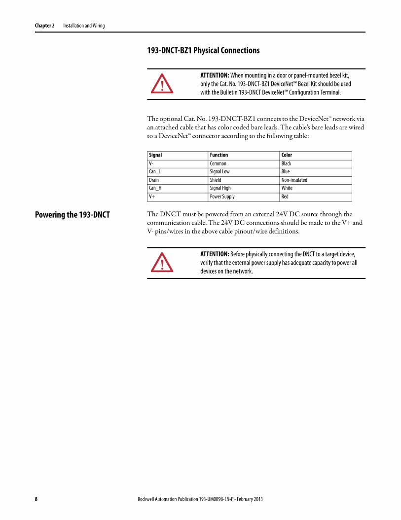
193-DNCT-BZ1 Physical Connections
The optional Cat. No. 193-DNCT-BZ1 connects to the DeviceNet™ network via an attached cable that has color coded bare leads. The cable’s bare leads are wired to a DeviceNet™ connector according to the following table:
Powering the 193-DNCT The DNCT must be powered from an external 24V DC source through the communication cable. The 24V DC connections should be made to the V+ and V- pins/wires in the above cable pinout/wire definitions.
ATTENTION: When mounting in a door or panel-mounted bezel kit, only the Cat. No. 193-DNCT-BZ1 DeviceNet™ Bezel Kit should be used with the Bulletin 193-DNCT DeviceNet™ Configuration Terminal.
Signal Function ColorV- Common BlackCan_L Signal Low BlueDrain Shield Non-insulatedCan_H Signal High WhiteV+ Power Supply Red
ATTENTION: Before physically connecting the DNCT to a target device, verify that the external power supply has adequate capacity to power all devices on the network.
8 Rockwell Automation Publication 193-UM009B-EN-P - February 2013
Chapter 3
Physical Features
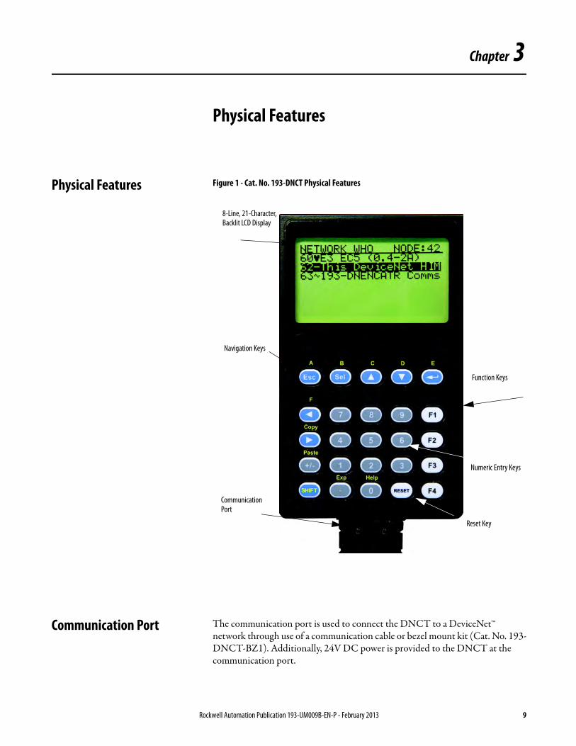
Physical Features Figure 1 - Cat. No. 193-DNCT Physical Features
Communication Port The communication port is used to connect the DNCT to a DeviceNet™ network through use of a communication cable or bezel mount kit (Cat. No. 193-DNCT-BZ1). Additionally, 24V DC power is provided to the DNCT at the communication port.
8-Line, 21-Character, Backlit LCD Display
Function Keys
Numeric Entry Keys
Navigation Keys
Communication Port
Reset Key
Rockwell Automation Publication 193-UM009B-EN-P - February 2013 9
Chapter 3 Physical Features
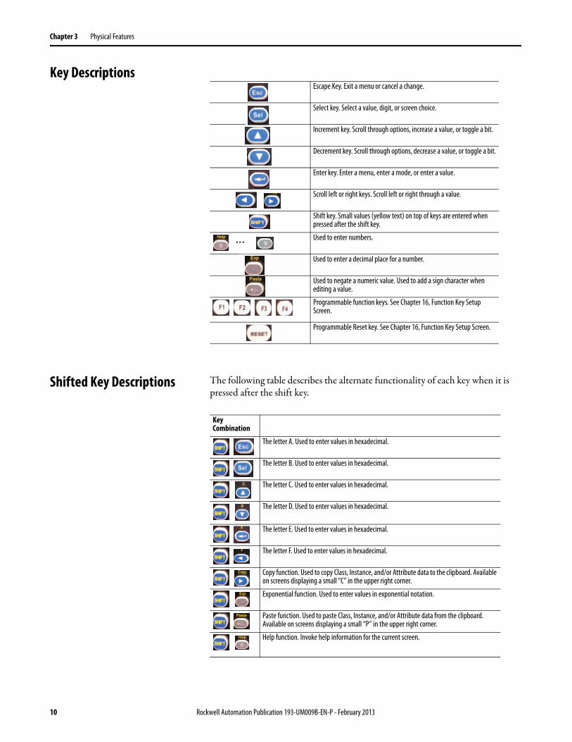
Key Descriptions
Shifted Key Descriptions The following table describes the alternate functionality of each key when it is pressed after the shift key.
Escape Key. Exit a menu or cancel a change.
Select key. Select a value, digit, or screen choice.
Increment key. Scroll through options, increase a value, or toggle a bit.
Decrement key. Scroll through options, decrease a value, or toggle a bit.
Enter key. Enter a menu, enter a mode, or enter a value.
Scroll left or right keys. Scroll left or right through a value.
Shift key. Small values (yellow text) on top of keys are entered when pressed after the shift key.
Used to enter numbers.
Used to enter a decimal place for a number.
Used to negate a numeric value. Used to add a sign character when editing a value.
Programmable function keys. See Chapter 16, Function Key Setup Screen.
Programmable Reset key. See Chapter 16, Function Key Setup Screen.
…
Key Combination
The letter A. Used to enter values in hexadecimal.
The letter B. Used to enter values in hexadecimal.
The letter C. Used to enter values in hexadecimal.
The letter D. Used to enter values in hexadecimal.
The letter E. Used to enter values in hexadecimal.
The letter F. Used to enter values in hexadecimal.
Copy function. Used to copy Class, Instance, and/or Attribute data to the clipboard. Available on screens displaying a small “C” in the upper right corner.
Exponential function. Used to enter values in exponential notation.
Paste function. Used to paste Class, Instance, and/or Attribute data from the clipboard. Available on screens displaying a small “P” in the upper right corner.
Help function. Invoke help information for the current screen.
10 Rockwell Automation Publication 193-UM009B-EN-P - February 2013
Chapter 4
Quick Start
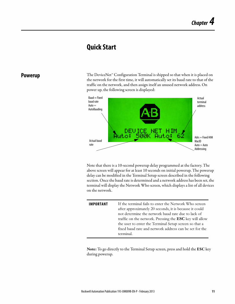
Powerup The DeviceNet™ Configuration Terminal is shipped so that when it is placed on the network for the first time, it will automatically set its baud rate to that of the traffic on the network, and then assign itself an unused network address. On power up, the following screen is displayed:
Note that there is a 10-second powerup delay programmed at the factory. The above screen will appear for at least 10 seconds on initial powerup. The powerup delay can be modified in the Terminal Setup screen described in the following section. Once the baud rate is determined and a network address has been set, the terminal will display the Network Who screen, which displays a list of all devices on the network.
Note: To go directly to the Terminal Setup screen, press and hold the ESC key during powerup.
IMPORTANT If the terminal fails to enter the Network Who screen
after approximately 20 seconds, it is because it could
not determine the network baud rate due to lack of
traffic on the network. Pressing the ESC key will allow
the user to enter the Terminal Setup screen so that a
fixed baud rate and network address can be set for the
terminal.
Baud = Fixed baud rate Auto = AutoBauding
Actual baud rate
Adrs = Fixed HIM MacID Auto = Auto Addressing
Actual terminal address
Rockwell Automation Publication 193-UM009B-EN-P - February 2013 11
Chapter 4 Quick Start
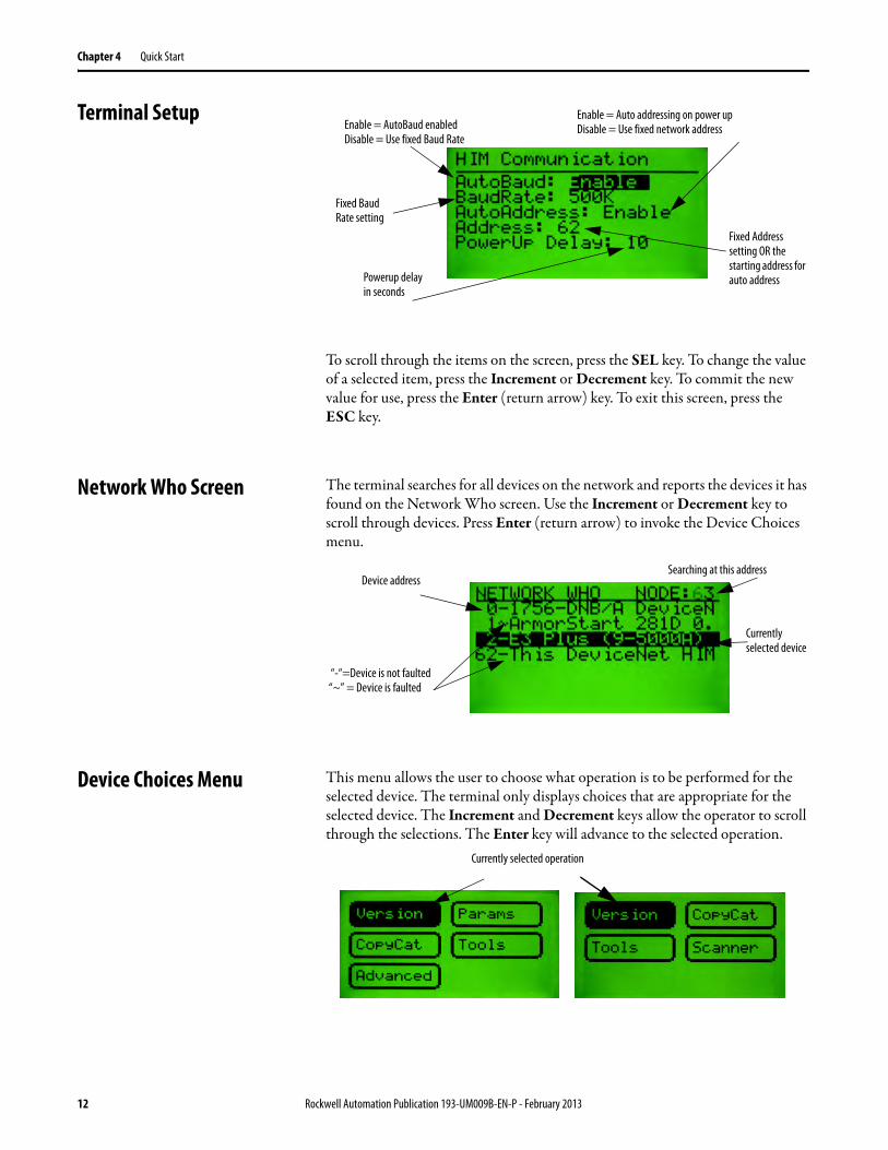
Terminal Setup
To scroll through the items on the screen, press the SEL key. To change the value of a selected item, press the Increment or Decrement key. To commit the new value for use, press the Enter (return arrow) key. To exit this screen, press the ESC key.
Network Who Screen The terminal searches for all devices on the network and reports the devices it has found on the Network Who screen. Use the Increment or Decrement key to scroll through devices. Press Enter (return arrow) to invoke the Device Choices menu.
Device Choices Menu This menu allows the user to choose what operation is to be performed for the selected device. The terminal only displays choices that are appropriate for the selected device. The Increment and Decrement keys allow the operator to scroll through the selections. The Enter key will advance to the selected operation.
Powerup delay in seconds
Fixed Address setting OR the starting address for auto address
Enable = AutoBaud enabled Disable = Use fixed Baud Rate
Fixed Baud Rate setting
Enable = Auto addressing on power up Disable = Use fixed network address
Searching at this address
Currently selected device
Device address
“-“=Device is not faulted “~” = Device is faulted
Currently selected operation
12 Rockwell Automation Publication 193-UM009B-EN-P - February 2013
Quick Start Chapter 4
Version: Displays Version information for the selected device.
Params: Provides access to configuration and status parameters for the selected device. Allows the operator to search for parameters that are not at factory defaults.
Copy Cat: Upload and store complete device configurations, including DeviceLogix™ programs to the programming terminal’s memory. Download stored device configurations from the programming terminal memory to the selected device.
Tools: Provides access to Node Commissioning functions, the Class Instance Attribute editor, and the real time graphing function.
Advanced: Provides access to the DeviceLogix™ editor, DeviceNet™ IO message timing information, ZIP configuration, and local input and output status display.
Scanner: If the selected device is a DeviceNet™ scanner, provides access to simple scanner configuration values and access to the scan list.
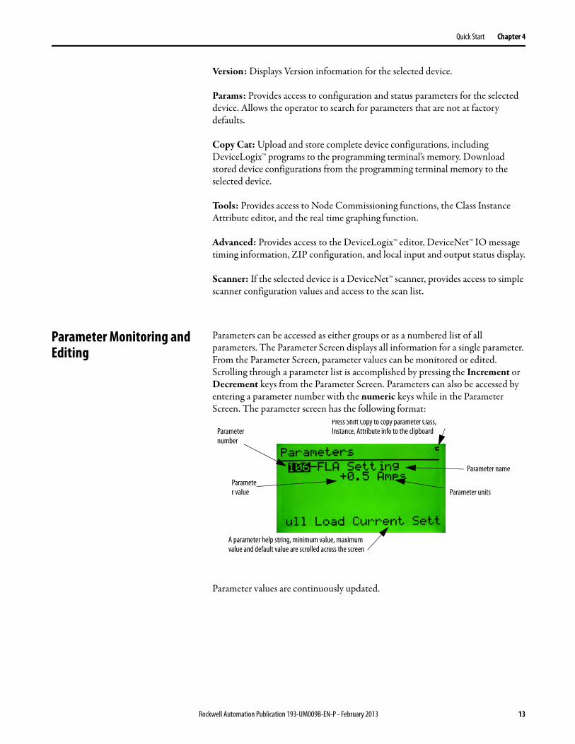
Parameter Monitoring and Editing
Parameters can be accessed as either groups or as a numbered list of all parameters. The Parameter Screen displays all information for a single parameter. From the Parameter Screen, parameter values can be monitored or edited. Scrolling through a parameter list is accomplished by pressing the Increment or Decrement keys from the Parameter Screen. Parameters can also be accessed by entering a parameter number with the numeric keys while in the Parameter Screen. The parameter screen has the following format:
Parameter values are continuously updated.
Press Shift Copy to copy parameter Class, Instance, Attribute info to the clipboardParameter
number
Parameter name
Parameter value Parameter units
A parameter help string, minimum value, maximum value and default value are scrolled across the screen
Rockwell Automation Publication 193-UM009B-EN-P - February 2013 13
Chapter 4 Quick Start
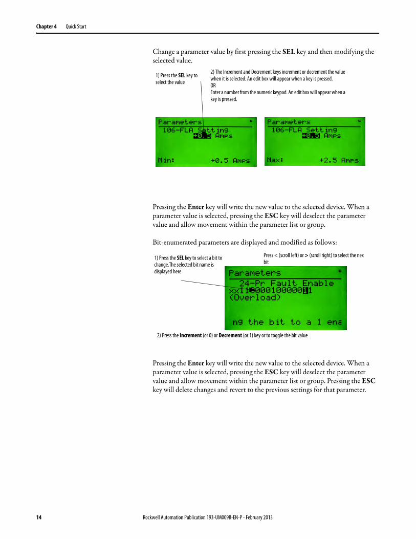
Change a parameter value by first pressing the SEL key and then modifying the selected value.
Pressing the Enter key will write the new value to the selected device. When a parameter value is selected, pressing the ESC key will deselect the parameter value and allow movement within the parameter list or group.
Bit-enumerated parameters are displayed and modified as follows:
Pressing the Enter key will write the new value to the selected device. When a parameter value is selected, pressing the ESC key will deselect the parameter value and allow movement within the parameter list or group. Pressing the ESC key will delete changes and revert to the previous settings for that parameter.
1) Press the SEL key to select the value
2) The Increment and Decrement keys increment or decrement the value when it is selected. An edit box will appear when a key is pressed. OR Enter a number from the numeric keypad. An edit box will appear when a key is pressed.
1) Press the SEL key to select a bit to change.The selected bit name is displayed here
Press < (scroll left) or > (scroll right) to select the nextbit
2) Press the Increment (or 0) or Decrement (or 1) key or to toggle the bit value
14 Rockwell Automation Publication 193-UM009B-EN-P - February 2013
Quick Start Chapter 4
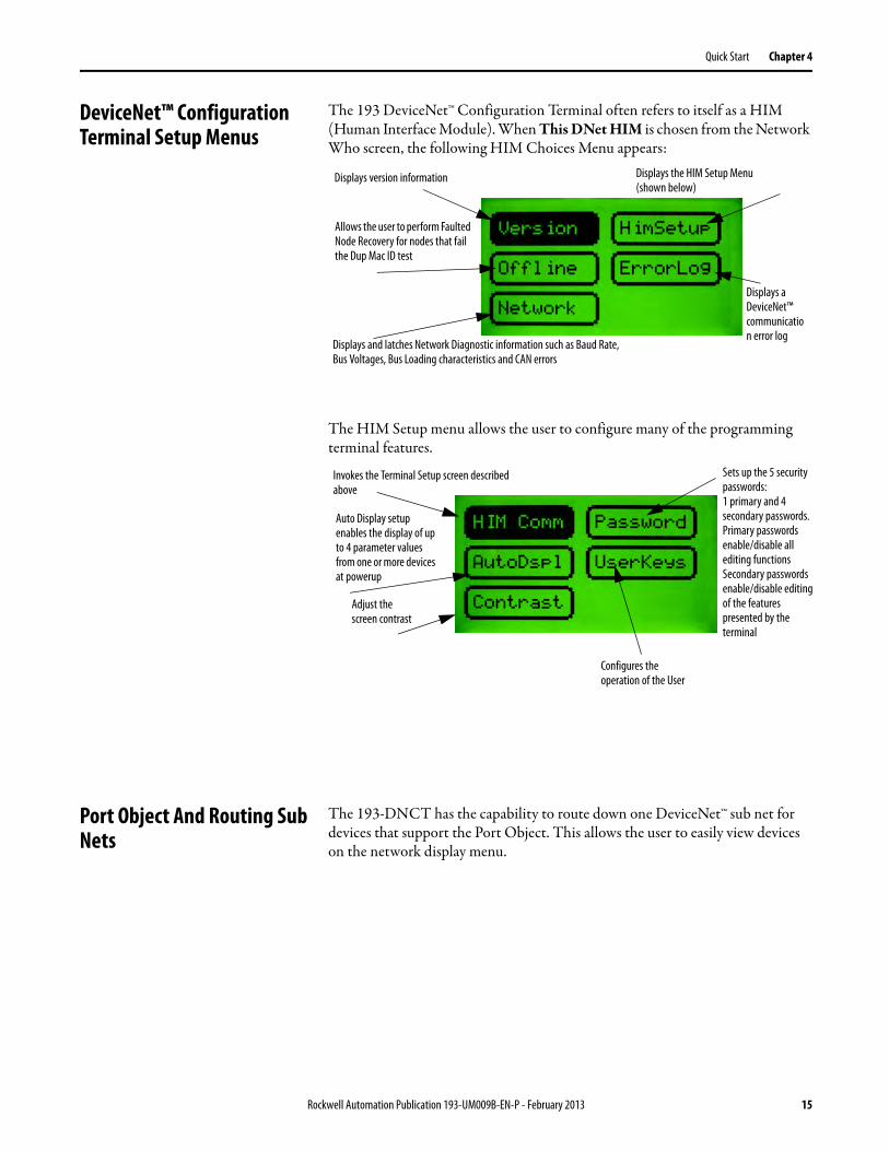
DeviceNet™ Configuration Terminal Setup Menus
The 193 DeviceNet™ Configuration Terminal often refers to itself as a HIM (Human Interface Module). When This DNet HIM is chosen from the Network Who screen, the following HIM Choices Menu appears:
The HIM Setup menu allows the user to configure many of the programming terminal features.
Port Object And Routing Sub Nets
The 193-DNCT has the capability to route down one DeviceNet™ sub net for devices that support the Port Object. This allows the user to easily view devices on the network display menu.
Displays version information
Allows the user to perform Faulted Node Recovery for nodes that fail the Dup Mac ID test
Displays and latches Network Diagnostic information such as Baud Rate, Bus Voltages, Bus Loading characteristics and CAN errors
Displays the HIM Setup Menu (shown below)
Displays a DeviceNet™ communication error log
Invokes the Terminal Setup screen described above
Sets up the 5 security passwords: 1 primary and 4 secondary passwords. Primary passwords enable/disable all editing functions Secondary passwords enable/disable editing of the features presented by the terminal
Auto Display setup enables the display of up to 4 parameter values from one or more devices at powerup
Configures the operation of the User
Adjust the screen contrast
Rockwell Automation Publication 193-UM009B-EN-P - February 2013 15

Chapter 4 Quick Start
Who Menu Display The Who Menu displays the device information for devices that support a DeviceNet™ sub net.
When the +DeviceNet Subnet choice is selected and the Enter key is pressed, the Subnet Who Menu will be displayed.
Selecting a device at the Subnet Who menu and pressing the Enter key will display all of the menus available at the standard Who menu.
16 Rockwell Automation Publication 193-UM009B-EN-P - February 2013
Chapter 5
Device Choices Menu
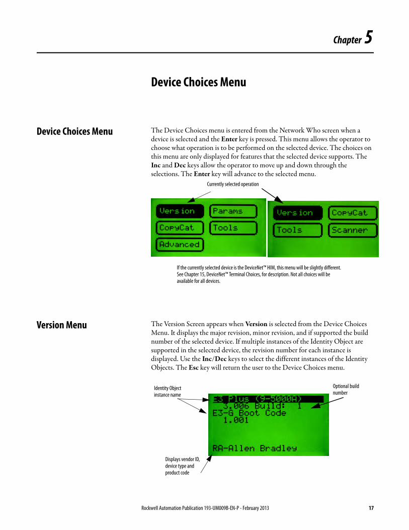
Device Choices Menu The Device Choices menu is entered from the Network Who screen when a device is selected and the Enter key is pressed. This menu allows the operator to choose what operation is to be performed on the selected device. The choices on this menu are only displayed for features that the selected device supports. The Inc and Dec keys allow the operator to move up and down through the selections. The Enter key will advance to the selected menu.
Version Menu The Version Screen appears when Version is selected from the Device Choices Menu. It displays the major revision, minor revision, and if supported the build number of the selected device. If multiple instances of the Identity Object are supported in the selected device, the revision number for each instance is displayed. Use the Inc/Dec keys to select the different instances of the Identity Objects. The Esc key will return the user to the Device Choices menu.
Currently selected operation
If the currently selected device is the DeviceNet™ HIM, this menu will be slightly different. See Chapter 15, DeviceNet™ Terminal Choices, for description. Not all choices will be available for all devices.
Displays vendor ID, device type and product code
Optional build number
Identity Object instance name
Rockwell Automation Publication 193-UM009B-EN-P - February 2013 17
Chapter 5 Device Choices Menu
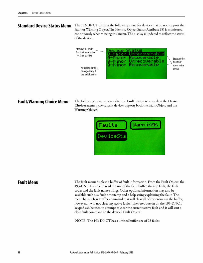
Standard Device Status Menu The 193-DNCT displays the following menu for devices that do not support the Fault or Warning Object.The Identity Object Status Attribute (5) is monitored continuously when viewing this menu. The display is updated to reflect the status of the device.
Fault/Warning Choice Menu The following menu appears after the Fault button is pressed on the Device Choices menu if the current device supports both the Fault Object and the Warning Object.
Fault Menu The fault menu displays a buffer of fault information. From the Fault Object, the 193-DNCT is able to read the size of the fault buffer, the trip fault, the fault codes and the fault name strings. Other optional information may also be available such as a fault timestamp and a help string explaining the fault. The menu has a Clear Buffer command that will clear all of the entries in the buffer, however, it will not clear any active faults. The reset button on the 193-DNCT keypad can be used to attempt to clear the current active fault and it will sent a clear fault command to the device's Fault Object.
NOTE: The 193-DNCT has a limited buffer size of 25 faults
Status of the Fault 0= Fault is not active 1= Fault is active
Status of the four fault states in the deviceNote: Help String is
displayed only if the fault is active
18 Rockwell Automation Publication 193-UM009B-EN-P - February 2013
Device Choices Menu Chapter 5
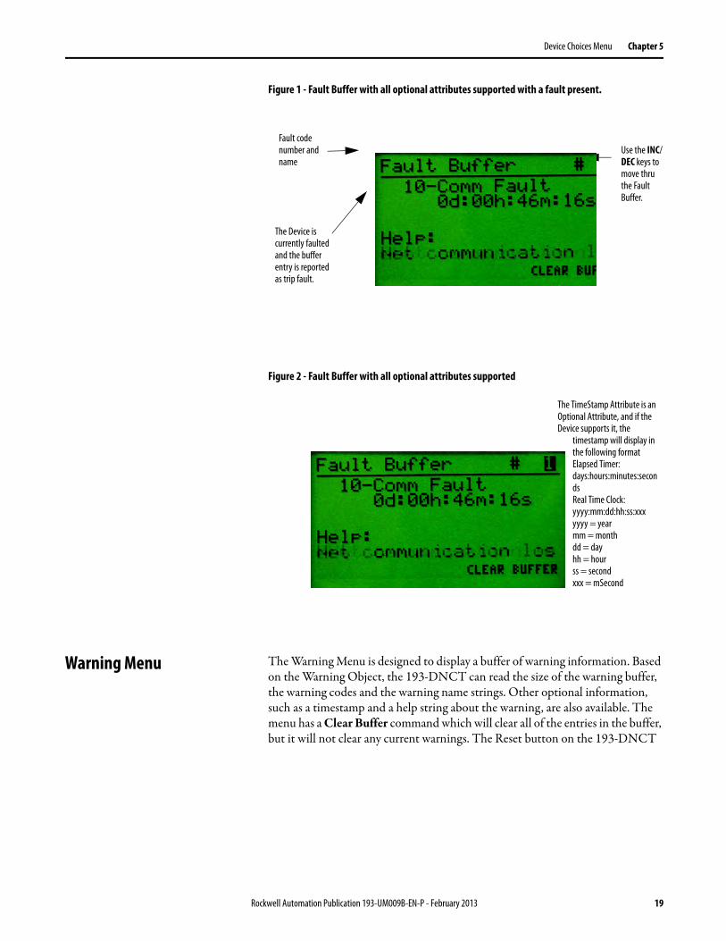
Figure 1 - Fault Buffer with all optional attributes supported with a fault present.
Figure 2 - Fault Buffer with all optional attributes supported
Warning Menu The Warning Menu is designed to display a buffer of warning information. Based on the Warning Object, the 193-DNCT can read the size of the warning buffer, the warning codes and the warning name strings. Other optional information, such as a timestamp and a help string about the warning, are also available. The menu has a Clear Buffer command which will clear all of the entries in the buffer, but it will not clear any current warnings. The Reset button on the 193-DNCT
Use the INC/DEC keys to move thru the Fault Buffer.
Fault code number and name
The Device is currently faulted and the buffer entry is reported as trip fault.
The TimeStamp Attribute is an Optional Attribute, and if the Device supports it, the
timestamp will display in the following formatElapsed Timer: days:hours:minutes:seconds Real Time Clock: yyyy:mm:dd:hh:ss:xxx yyyy = year mm = month dd = day hh = hour ss = second xxx = mSecond
Rockwell Automation Publication 193-UM009B-EN-P - February 2013 19

Chapter 5 Device Choices Menu
keypad can be used to attempt to clear the current warning by sending a clear warning command to the devices Warning Object.
Figure 3 - Warning Buffer without optional attributes supported
Warning code number and name
Warning code number and name
Use the SEL key to move back and forth from the Buffer number to the Clear Buffer Command. With the Clear Buffer choice highlighted, press the Enter key to clear the buffer.
20 Rockwell Automation Publication 193-UM009B-EN-P - February 2013

Chapter 6
Parameter Choices Menu
Parameter Choices Menu The Parameter Choices Menu is only available if the selected device has built-in parameter support (DeviceNet™ Parameter Object). This menu allows the operator to go to screens that monitor and change parameters, view/select parameter groups, and search for parameters that are not at their default settings. The Inc and Dec keys allow the operator to move up and down through the selections. The Enter key advances the user to the selected item. The Esc key returns the user to the Device Choices Menu.
Groups Screen This screen allows the operator to select a group of parameters to be monitored/edited. The Inc and Dec keys allow the operator to move up and down through the selections. The Enter key advances the operator to a Parameter Edit Screen. The Esc key will return the user to the Parameter Choices Menu. The choices in this menu are only displayed for groups that the selected device supports.
Num List Selection A numerical list (Num List) of Parameter Edit Screens are presented when Num List is selected and the Enter key is pressed.
Currently selected function
Currently selected parameter group
Parameter group names
Rockwell Automation Publication 193-UM009B-EN-P - February 2013 21
Chapter 6 Parameter Choices Menu
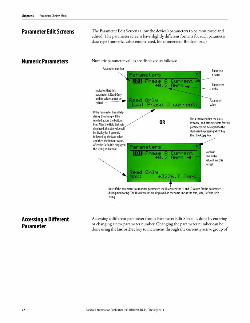
Parameter Edit Screens The Parameter Edit Screens allow the device’s parameters to be monitored and edited. The parameter screens have slightly different formats for each parameter data type (numeric, value enumerated, bit enumerated Boolean, etc.)
Numeric Parameters Numeric parameter values are displayed as follows:
Accessing a Different Parameter
Accessing a different parameter from a Parameter Edit Screen is done by entering or changing a new parameter number. Changing the parameter number can be done using the Inc or Dec key to increment through the currently active group of
OR
Parameter number
Indicates that this parameter is Read Only and its value cannot be edited.
Parameter units
Parameter name
Parameter value
This c indicates that the Class, Instance, and Attribute data for this parameter can be copied to the clipboard by pressing Shift key then the Copy Key.
If the Parameter has a Help string, the string will be scrolled across the bottom line. After the Help String is displayed, the Min value will be display for 3 seconds, followed by the Max value, and then the Default value. After the Default is displayed the string will repeat.
Numeric Parameter values have this format
Note: If the parameter is a monitor parameter, the HIM stores the HI and LO values for the parameter during monitoring. The HI:/LO: values are displayed on the same line as the Min, Max, Def and Help string.
22 Rockwell Automation Publication 193-UM009B-EN-P - February 2013

Parameter Choices Menu Chapter 6
parameters. Entering a new parameter number directly can be done by entering a number with the numeric keypad (only if accessed through the Num List).
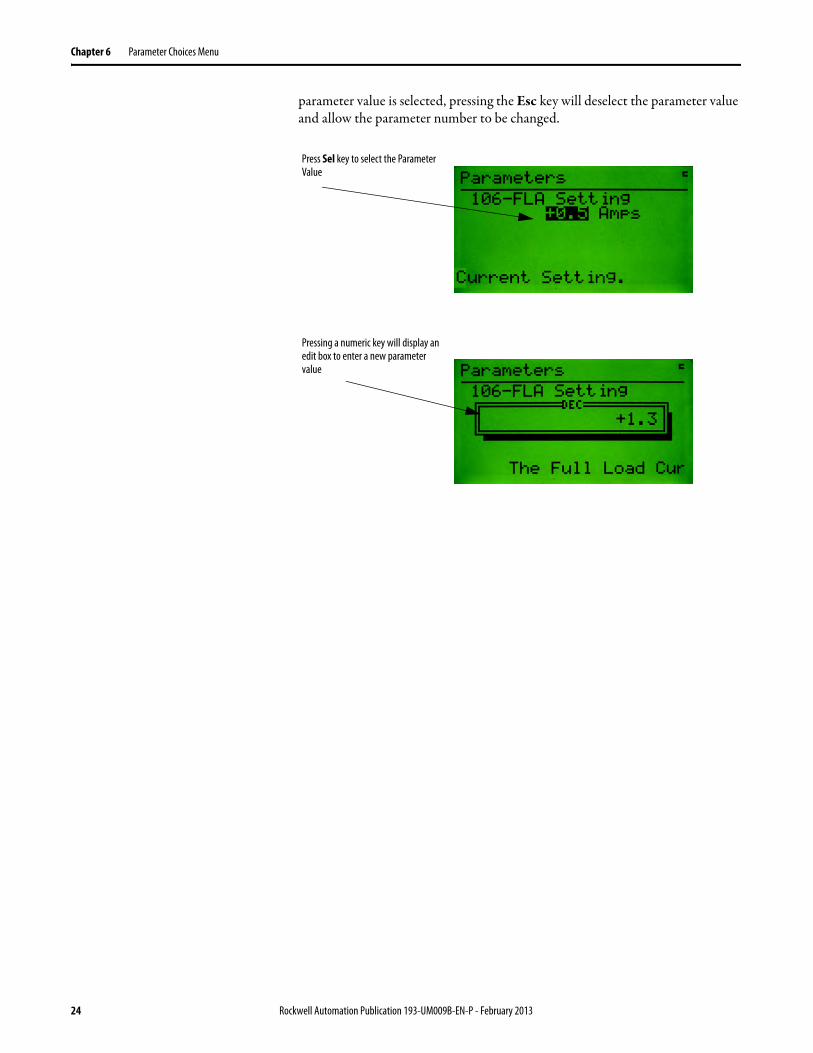
Changing a Parameter Value Changing a parameter value is done by pressing the Sel key to highlight the parameter value then using the Inc/Dec keys or numeric keys to enter the value. Pressing the Enter key will write the new value to the parameter. When the
Current parameter number
Pressing a numeric key will displayed an edit box to enter a new parameter number in.
Rockwell Automation Publication 193-UM009B-EN-P - February 2013 23
Chapter 6 Parameter Choices Menu
parameter value is selected, pressing the Esc key will deselect the parameter value and allow the parameter number to be changed.
Press Sel key to select the Parameter Value
Pressing a numeric key will display an edit box to enter a new parameter value
24 Rockwell Automation Publication 193-UM009B-EN-P - February 2013
Parameter Choices Menu Chapter 6
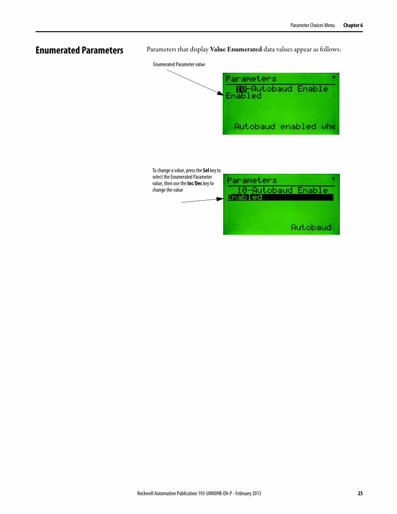
Enumerated Parameters Parameters that display Value Enumerated data values appear as follows:
Enumerated Parameter value
To change a value, press the Sel key to select the Enumerated Parameter value, then use the Inc/Dec key to change the value
Rockwell Automation Publication 193-UM009B-EN-P - February 2013 25
Chapter 6 Parameter Choices Menu
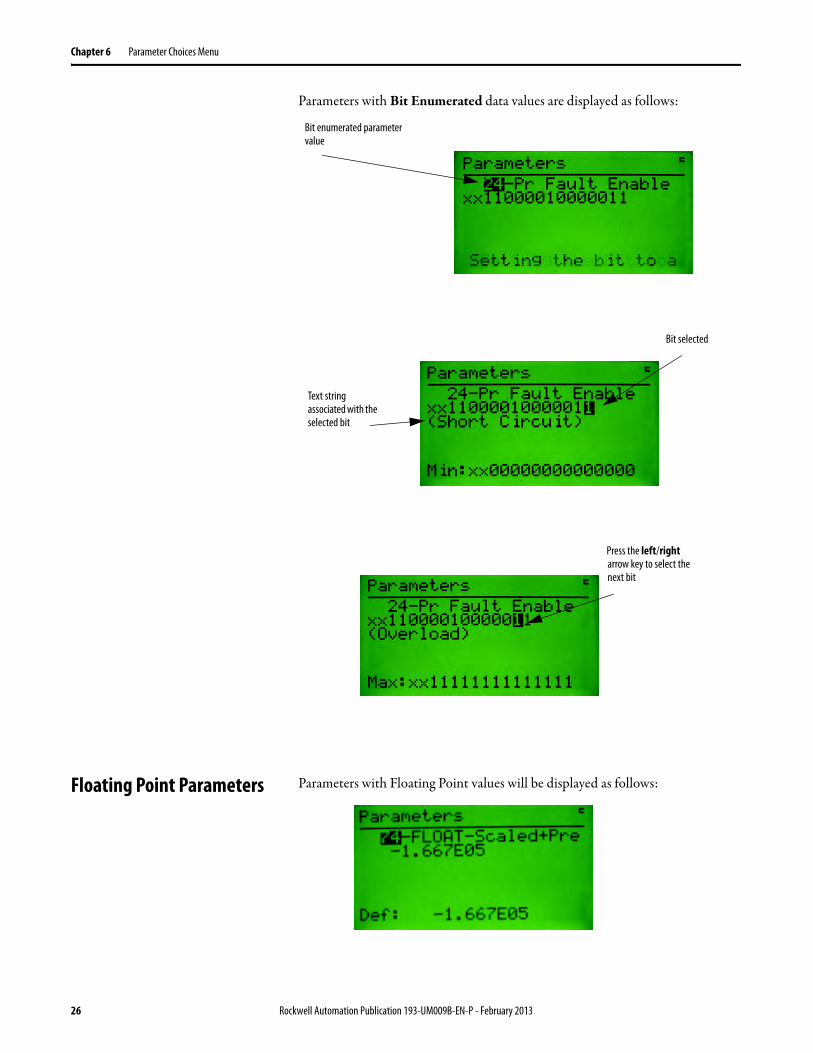
Parameters with Bit Enumerated data values are displayed as follows:
Floating Point Parameters Parameters with Floating Point values will be displayed as follows:
Bit enumerated parameter value
Bit selected
Text string associated with the selected bit
Press the left/right arrow key to select the next bit
26 Rockwell Automation Publication 193-UM009B-EN-P - February 2013

Parameter Choices Menu Chapter 6
Entering floating point numbers is performed much the same as regular numeric parameters described earlier. The exponential (displayed as an “E”) is entered as follows:
Search for Changed Parameters
This function is invoked by selecting the Search option from the Parameter Choices Menu. The function searches through the selected device’s parameters and finds the parameters that are not at their default setting. The following screen is displayed when searching the parameter list for the selected device:
When all the parameters have been checked, a list of parameters that are not at their default value will be displayed. The Inc and Dec keys allow the operator to move up and down through the non-default parameters. Pressing the Enter key allows the parameter value to be viewed/edited.
When accessing parameters found by the Search function, the format of the parameter screen will be similar to a Parameter Edit Screen with a few changes. The title line will say “Non-Default Parameter”, and when Inc or Dec is pressed, only the parameter found in the search will be displayed
Use the Shift key then the Exp key to add the E into the value when editing a floating point value
Number of parameters to search through
Number of non-default parameters found
Current parameter being checked for default value
Selected parameter
Parameter number of non-default parameters
Names of non-default parameters
Rockwell Automation Publication 193-UM009B-EN-P - February 2013 27
Chapter 6 Parameter Choices Menu
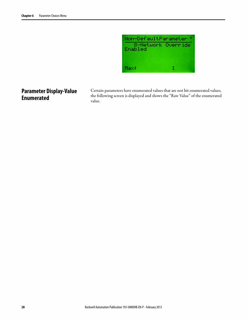
Parameter Display-Value Enumerated
Certain parameters have enumerated values that are not bit enumerated values, the following screen is displayed and shows the “Raw Value” of the enumerated value.
28 Rockwell Automation Publication 193-UM009B-EN-P - February 2013
Chapter 7
Copy Cat Menu
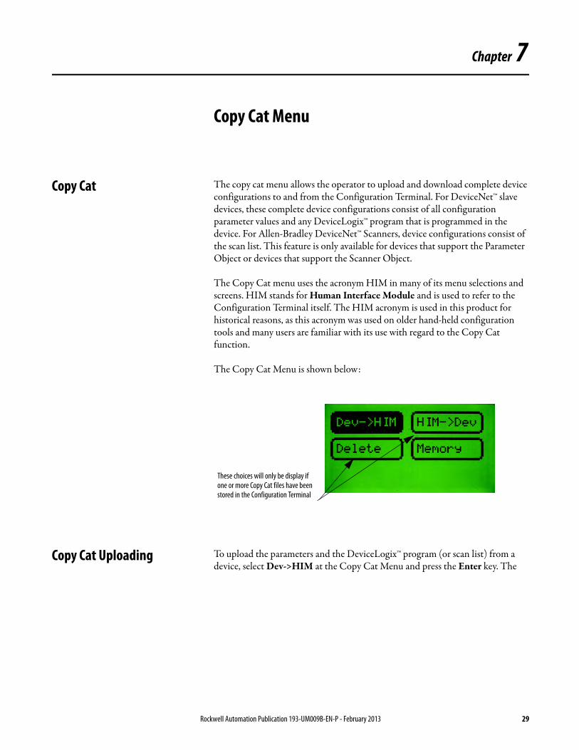
Copy Cat The copy cat menu allows the operator to upload and download complete device configurations to and from the Configuration Terminal. For DeviceNet™ slave devices, these complete device configurations consist of all configuration parameter values and any DeviceLogix™ program that is programmed in the device. For Allen-Bradley DeviceNet™ Scanners, device configurations consist of the scan list. This feature is only available for devices that support the Parameter Object or devices that support the Scanner Object.
The Copy Cat menu uses the acronym HIM in many of its menu selections and screens. HIM stands for Human Interface Module and is used to refer to the Configuration Terminal itself. The HIM acronym is used in this product for historical reasons, as this acronym was used on older hand-held configuration tools and many users are familiar with its use with regard to the Copy Cat function.
The Copy Cat Menu is shown below:
Copy Cat Uploading To upload the parameters and the DeviceLogix™ program (or scan list) from a device, select Dev->HIM at the Copy Cat Menu and press the Enter key. The
These choices will only be display if one or more Copy Cat files have been stored in the Configuration Terminal
Rockwell Automation Publication 193-UM009B-EN-P - February 2013 29
Chapter 7 Copy Cat Menu
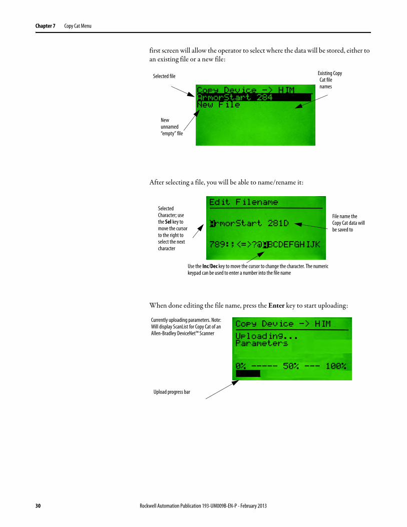
first screen will allow the operator to select where the data will be stored, either to an existing file or a new file:
After selecting a file, you will be able to name/rename it:
When done editing the file name, press the Enter key to start uploading:
Selected file
New unnamed “empty” file
Existing Copy Cat file names
File name the Copy Cat data will be saved to
Selected Character; use the Sel key to move the cursor to the right to select the next character
Use the Inc/Dec key to move the cursor to change the character. The numeric keypad can be used to enter a number into the file name
Upload progress bar
Currently uploading parameters. Note: Will display ScanList for Copy Cat of an Allen-Bradley DeviceNet™ Scanner
30 Rockwell Automation Publication 193-UM009B-EN-P - February 2013

Copy Cat Menu Chapter 7
Once the parameters are uploaded, the DeviceLogix™ program will be uploaded (if applicable):
When the upload is complete, the screen will appear as follows:
Copy Cat Downloading To download complete device configuration files that have been stored in the Configuration Terminal, select HIM->Dev at the Copy Cat Menu. The first screen that appears will allow the operator to select which stored file to download:
Currently uploading the Logix program
Selected file to download
Rockwell Automation Publication 193-UM009B-EN-P - February 2013 31
Chapter 7 Copy Cat Menu
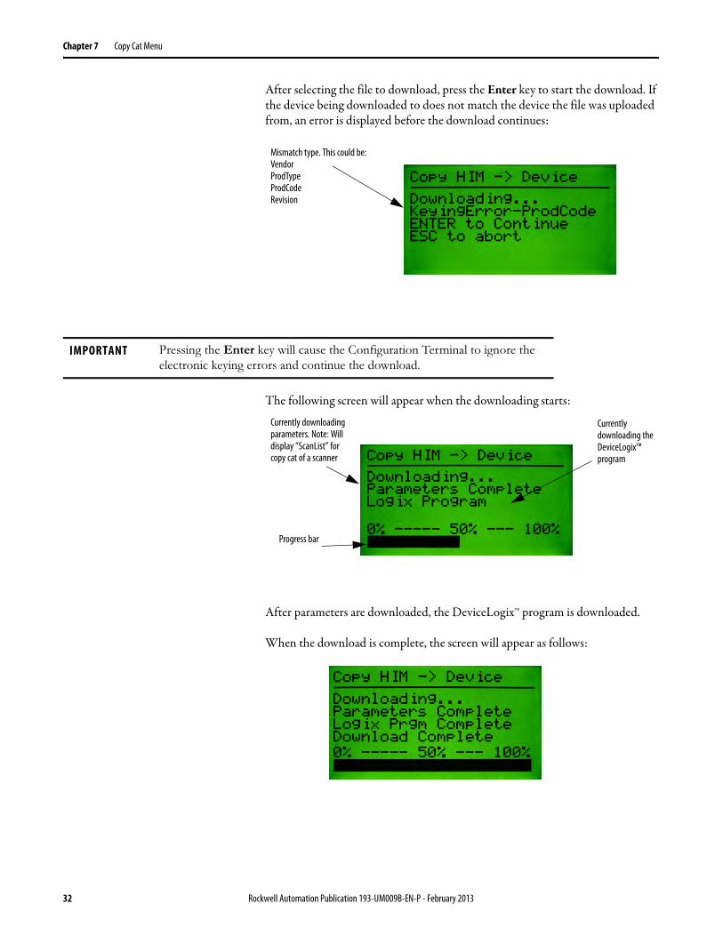
After selecting the file to download, press the Enter key to start the download. If the device being downloaded to does not match the device the file was uploaded from, an error is displayed before the download continues:
The following screen will appear when the downloading starts:
After parameters are downloaded, the DeviceLogix™ program is downloaded.
When the download is complete, the screen will appear as follows:
Mismatch type. This could be: Vendor ProdType ProdCode Revision
IMPORTANT Pressing the Enter key will cause the Configuration Terminal to ignore the
electronic keying errors and continue the download.
Currently downloading parameters. Note: Will display “ScanList” for copy cat of a scanner
Progress bar
Currently downloading the DeviceLogix™ program
32 Rockwell Automation Publication 193-UM009B-EN-P - February 2013
Copy Cat Menu Chapter 7
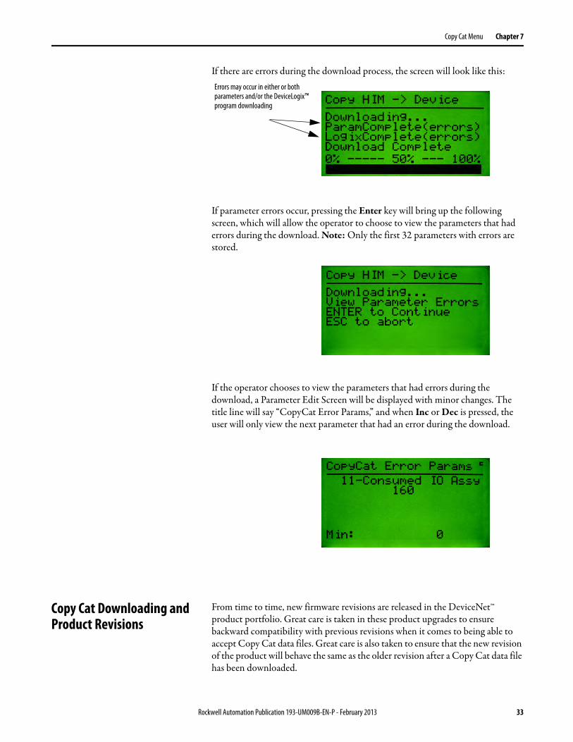
If there are errors during the download process, the screen will look like this:
If parameter errors occur, pressing the Enter key will bring up the following screen, which will allow the operator to choose to view the parameters that had errors during the download. Note: Only the first 32 parameters with errors are stored.
If the operator chooses to view the parameters that had errors during the download, a Parameter Edit Screen will be displayed with minor changes. The title line will say “CopyCat Error Params,” and when Inc or Dec is pressed, the user will only view the next parameter that had an error during the download..
Copy Cat Downloading and Product Revisions
From time to time, new firmware revisions are released in the DeviceNet™ product portfolio. Great care is taken in these product upgrades to ensure backward compatibility with previous revisions when it comes to being able to accept Copy Cat data files. Great care is also taken to ensure that the new revision of the product will behave the same as the older revision after a Copy Cat data file has been downloaded.
Errors may occur in either or both parameters and/or the DeviceLogix™ program downloading
Rockwell Automation Publication 193-UM009B-EN-P - February 2013 33
Chapter 7 Copy Cat Menu
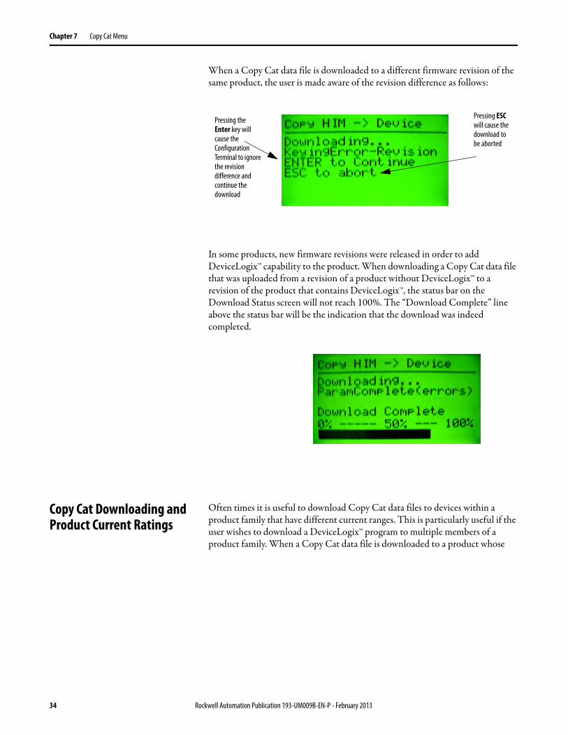
When a Copy Cat data file is downloaded to a different firmware revision of the same product, the user is made aware of the revision difference as follows:
In some products, new firmware revisions were released in order to add DeviceLogix™ capability to the product. When downloading a Copy Cat data file that was uploaded from a revision of a product without DeviceLogix™ to a revision of the product that contains DeviceLogix™, the status bar on the Download Status screen will not reach 100%. The “Download Complete” line above the status bar will be the indication that the download was indeed completed.
Copy Cat Downloading and Product Current Ratings
Often times it is useful to download Copy Cat data files to devices within a product family that have different current ranges. This is particularly useful if the user wishes to download a DeviceLogix™ program to multiple members of a product family. When a Copy Cat data file is downloaded to a product whose
Pressing the Enter key will cause the Configuration Terminal to ignore the revision difference and continue the download
Pressing ESC will cause the download to be aborted
34 Rockwell Automation Publication 193-UM009B-EN-P - February 2013
Copy Cat Menu Chapter 7
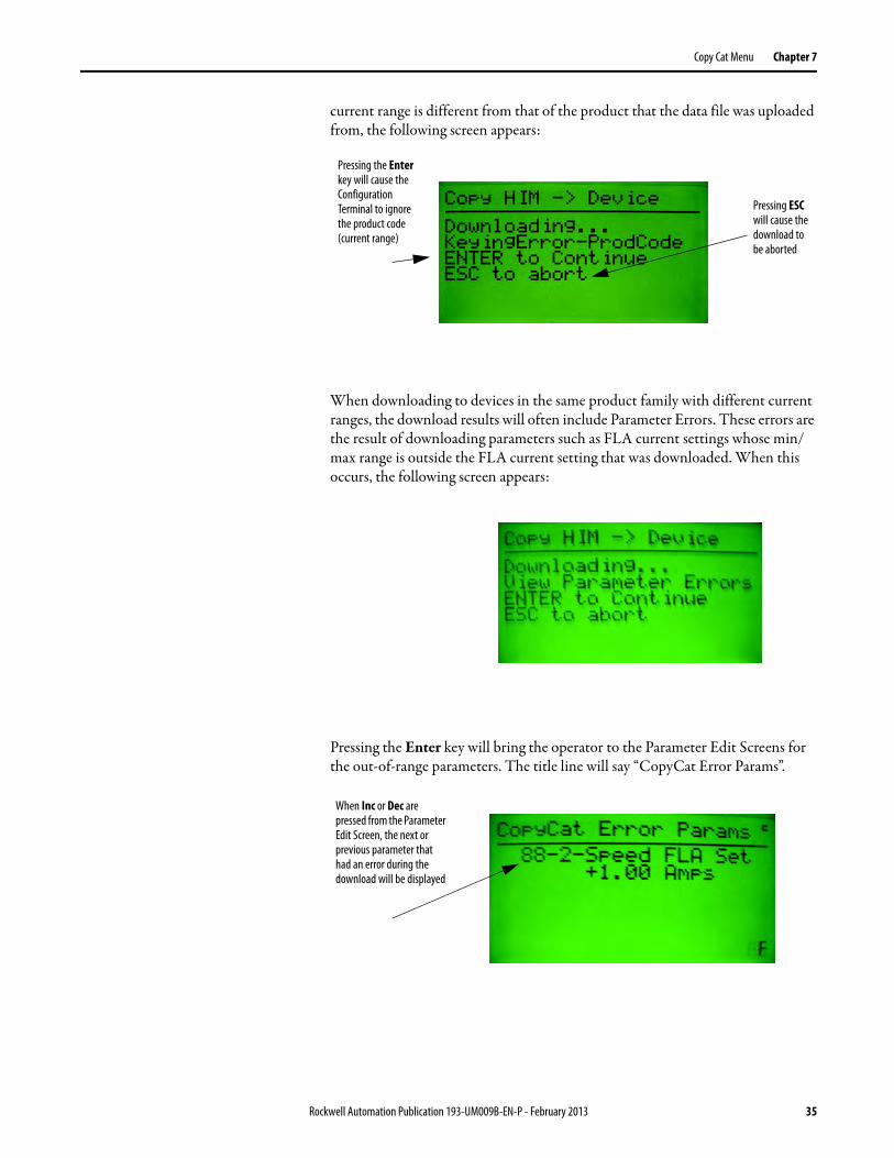
current range is different from that of the product that the data file was uploaded from, the following screen appears:
When downloading to devices in the same product family with different current ranges, the download results will often include Parameter Errors. These errors are the result of downloading parameters such as FLA current settings whose min/max range is outside the FLA current setting that was downloaded. When this occurs, the following screen appears:
Pressing the Enter key will bring the operator to the Parameter Edit Screens for the out-of-range parameters. The title line will say “CopyCat Error Params”.
Pressing the Enter key will cause the Configuration Terminal to ignore the product code (current range)
Pressing ESC will cause the download to be aborted
When Inc or Dec are pressed from the Parameter Edit Screen, the next or previous parameter that had an error during the download will be displayed
Rockwell Automation Publication 193-UM009B-EN-P - February 2013 35
Chapter 7 Copy Cat Menu
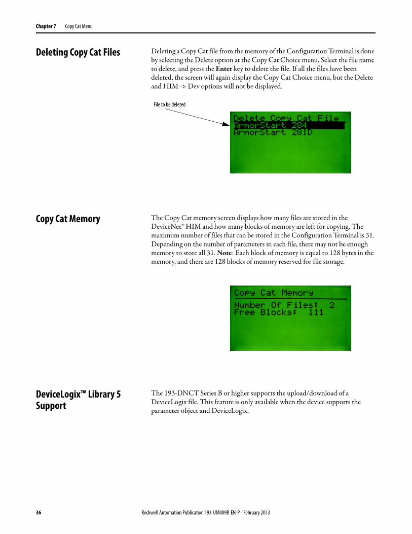
Deleting Copy Cat Files Deleting a Copy Cat file from the memory of the Configuration Terminal is done by selecting the Delete option at the Copy Cat Choice menu. Select the file name to delete, and press the Enter key to delete the file. If all the files have been deleted, the screen will again display the Copy Cat Choice menu, but the Delete and HIM -> Dev options will not be displayed.
Copy Cat Memory The Copy Cat memory screen displays how many files are stored in the DeviceNet™ HIM and how many blocks of memory are left for copying. The maximum number of files that can be stored in the Configuration Terminal is 31. Depending on the number of parameters in each file, there may not be enough memory to store all 31. Note: Each block of memory is equal to 128 bytes in the memory, and there are 128 blocks of memory reserved for file storage.
DeviceLogix™ Library 5 Support
The 193-DNCT Series B or higher supports the upload/download of a DeviceLogix file. This feature is only available when the device supports the parameter object and DeviceLogix.
File to be deleted
36 Rockwell Automation Publication 193-UM009B-EN-P - February 2013
Chapter 8
Tools Menu
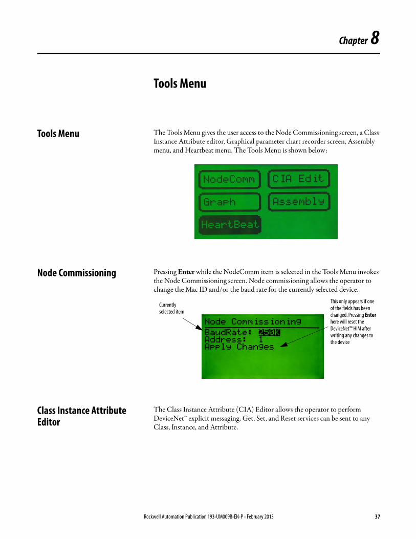
Tools Menu The Tools Menu gives the user access to the Node Commissioning screen, a Class Instance Attribute editor, Graphical parameter chart recorder screen, Assembly menu, and Heartbeat menu. The Tools Menu is shown below:
Node Commissioning Pressing Enter while the NodeComm item is selected in the Tools Menu invokes the Node Commissioning screen. Node commissioning allows the operator to change the Mac ID and/or the baud rate for the currently selected device.
Class Instance Attribute Editor
The Class Instance Attribute (CIA) Editor allows the operator to perform DeviceNet™ explicit messaging. Get, Set, and Reset services can be sent to any Class, Instance, and Attribute.
Currently selected item
This only appears if one of the fields has been changed. Pressing Enter here will reset the DeviceNet™ HIM after writing any changes to the device
Rockwell Automation Publication 193-UM009B-EN-P - February 2013 37

Chapter 8 Tools Menu
The Get service is outlined in the following screen description:
The Set service is outlined in the following screen description::
The Reset service is outlined in the following screen description:
Graph Setup Screens The Graph function allows the Configuration Terminal to become a simple graphing device. From the Graph Setup Screens, the user sets up to four Class, Instance, or Attributes to be monitored and displayed as a scrolling graph (similar
CIA Copy and Paste is available for this menu
Highlight and press the Enter key to
Selected service
Display size of read data. Choices: Byte, Word, Dword, or
Data that is read when a message is requested
Highlight and press the Enter key to perform the
Display size of data to write. Choices: Byte, Word, Dword,
Data to write
Highlight and press the Enter key to perform the Reset service
38 Rockwell Automation Publication 193-UM009B-EN-P - February 2013
Tools Menu Chapter 8
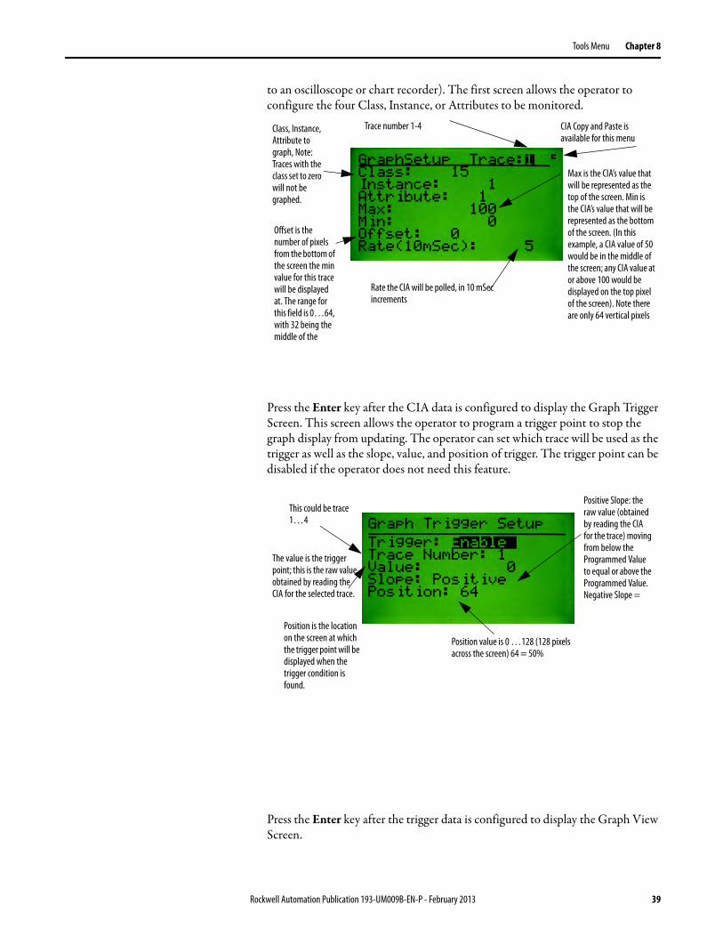
to an oscilloscope or chart recorder). The first screen allows the operator to configure the four Class, Instance, or Attributes to be monitored.
Press the Enter key after the CIA data is configured to display the Graph Trigger Screen. This screen allows the operator to program a trigger point to stop the graph display from updating. The operator can set which trace will be used as the trigger as well as the slope, value, and position of trigger. The trigger point can be disabled if the operator does not need this feature.
Press the Enter key after the trigger data is configured to display the Graph View Screen.
CIA Copy and Paste is available for this menu
Class, Instance, Attribute to graph, Note: Traces with the class set to zero will not be graphed.
Trace number 1-4
Max is the CIA’s value that will be represented as the top of the screen. Min is the CIA’s value that will be represented as the bottom of the screen. (In this example, a CIA value of 50 would be in the middle of the screen; any CIA value at or above 100 would be displayed on the top pixel of the screen). Note there are only 64 vertical pixels
Offset is the number of pixels from the bottom of the screen the min value for this trace will be displayed at. The range for this field is 0…64, with 32 being the middle of the
Rate the CIA will be polled, in 10 mSec increments
The value is the trigger point; this is the raw value obtained by reading the CIA for the selected trace.
This could be trace 1…4
Positive Slope: the raw value (obtained by reading the CIA for the trace) moving from below the Programmed Value to equal or above the Programmed Value.Negative Slope =
Position value is 0 …128 (128 pixels across the screen) 64 = 50%
Position is the location on the screen at which the trigger point will be displayed when the trigger condition is found.
Rockwell Automation Publication 193-UM009B-EN-P - February 2013 39
Chapter 8 Tools Menu
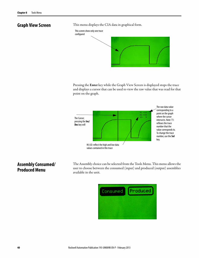
Graph View Screen This menu displays the CIA data in graphical form.
Pressing the Enter key while the Graph View Screen is displayed stops the trace and displays a cursor that can be used to view the raw value that was read for that point on the graph.
Assembly Consumed/Produced Menu
The Assembly choice can be selected from the Tools Menu. This menu allows the user to choose between the consumed (input) and produced (output) assemblies available in the unit.
This screen show only one trace configured
The raw data value corresponding to a point on the graph where the cursor intersects. Note: T1: reflexes the trace number that the value corresponds to. To change the trace number, use the Sel key.
The Cursor; pressing the Inc/Dec key will
HI:/LO: reflect the high and low data values contained in this trace
40 Rockwell Automation Publication 193-UM009B-EN-P - February 2013
Tools Menu Chapter 8
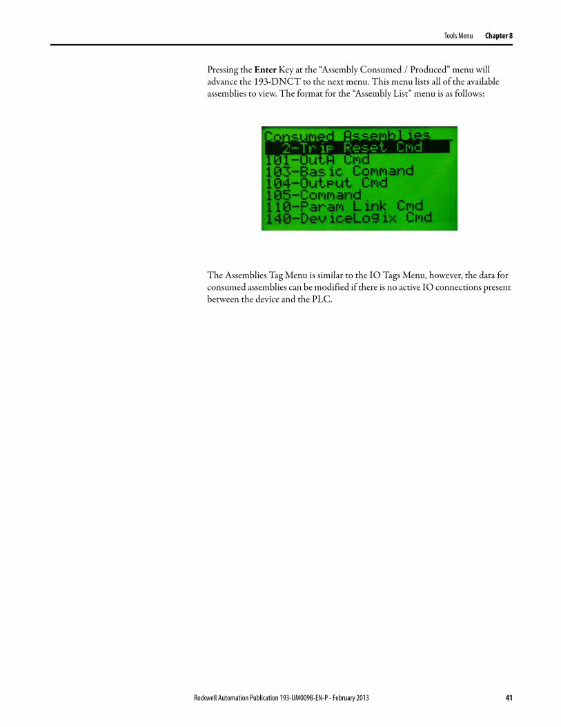
Pressing the Enter Key at the “Assembly Consumed / Produced” menu will advance the 193-DNCT to the next menu. This menu lists all of the available assemblies to view. The format for the “Assembly List” menu is as follows:
The Assemblies Tag Menu is similar to the IO Tags Menu, however, the data for consumed assemblies can be modified if there is no active IO connections present between the device and the PLC.
Rockwell Automation Publication 193-UM009B-EN-P - February 2013 41

Chapter 8 Tools Menu
Notes:
42 Rockwell Automation Publication 193-UM009B-EN-P - February 2013
Chapter 9
Advanced Functions Menu
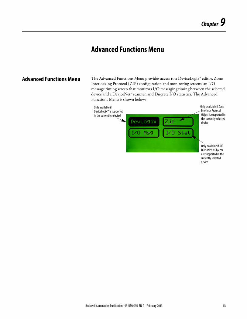
Advanced Functions Menu The Advanced Functions Menu provides access to a DeviceLogix™ editor, Zone Interlocking Protocol (ZIP) configuration and monitoring screens, an I/O message timing screen that monitors I/O messaging timing between the selected device and a DeviceNet™ scanner, and Discrete I/O statistics. The Advanced Functions Menu is shown below:
Only available if Zone Interlock Protocol Object is supported in the currently selected device
Only available if DIP, DOP or PNB Objects are supported in the currently selected device
Only available if DeviceLogix™ is supported in the currently selected
Rockwell Automation Publication 193-UM009B-EN-P - February 2013 43

Chapter 9 Advanced Functions Menu
Notes:
44 Rockwell Automation Publication 193-UM009B-EN-P - February 2013
Chapter 10
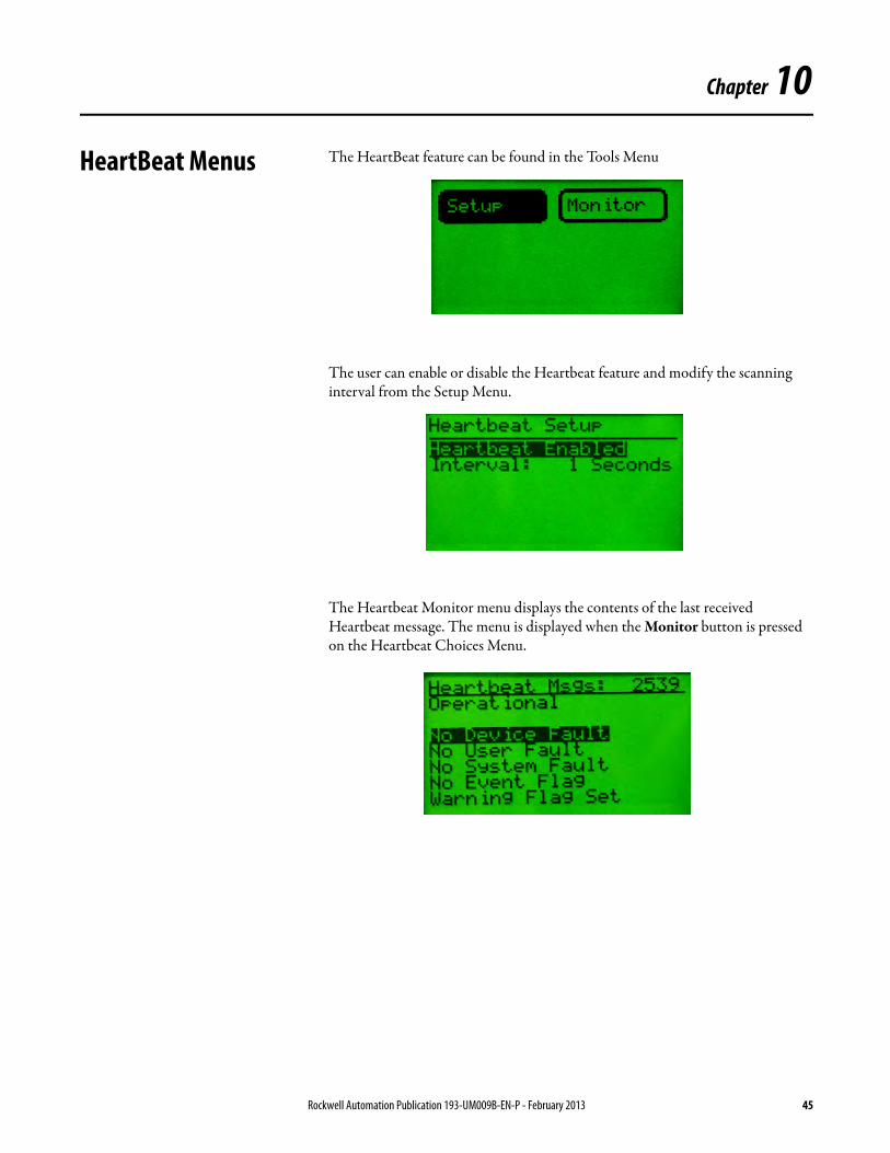
HeartBeat Menus The HeartBeat feature can be found in the Tools Menu
The user can enable or disable the Heartbeat feature and modify the scanning interval from the Setup Menu.
The Heartbeat Monitor menu displays the contents of the last received Heartbeat message. The menu is displayed when the Monitor button is pressed on the Heartbeat Choices Menu.
Rockwell Automation Publication 193-UM009B-EN-P - February 2013 45

Chapter 10
Notes:
46 Rockwell Automation Publication 193-UM009B-EN-P - February 2013
Chapter 11
I/O Message Monitoring
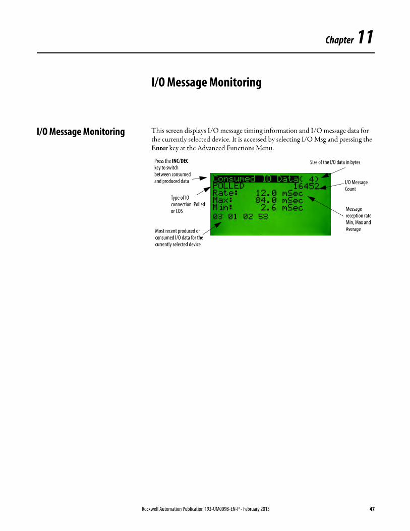
I/O Message Monitoring This screen displays I/O message timing information and I/O message data for the currently selected device. It is accessed by selecting I/O Msg and pressing the Enter key at the Advanced Functions Menu.
Press the INC/DEC key to switch between consumed and produced data
Type of IO connection. Polled or COS
I/O Message Count
Size of the I/O data in bytes
Most recent produced or consumed I/O data for the currently selected device
Message reception rate Min, Max and Average
Rockwell Automation Publication 193-UM009B-EN-P - February 2013 47

Chapter 11 I/O Message Monitoring
Notes:
48 Rockwell Automation Publication 193-UM009B-EN-P - February 2013

Chapter 12
DeviceLogix™ Functionality
DeviceLogix™ Functionality The Configuration Terminal allows the operator to monitor, edit or delete DeviceLogix™ programs for devices that support DeviceLogix™. DeviceLogix™ can also be enabled or disabled for a device. The DeviceLogix™ functions can be accessed through the DeviceLogix™ Choices Menu, which is accessed by pressing Enter from the Advanced Functions Menu while the DevLogix menu item is selected.
DeviceLogix™ Choices Menu The DeviceLogix™ Choices Menu is shown below:
DeviceLogix™ Monitor This function allows the operator to view a DeviceLogix™ program, including all programmed function blocks, Discrete Output Points (DOP) and Produced Network Bits (PNB). Text string for inputs, outputs, PNBs, and fault bits are displayed for devices that support the DeviceLogix™ Data Table Object. The counter and timer preset and accumulator value’s can be modified when selected. To view each function block, use the INC/DEC keys to move to the next function block. When the last programmed function block is reached, pressing the INC key will advance the screen to the Programmed DOP screen. Pressing the INC key again will then display the Programmed PNB screen and if the INC key is pressed a third time, the first function block will be displayed again. When viewing Function Blocks, the screen will have the following formats:
Only available if the DeviceLogix™ DataTable Object is supported in the currently selected device
Currently selected function
Rockwell Automation Publication 193-UM009B-EN-P - February 2013 49
Chapter 12 DeviceLogix™ Functionality
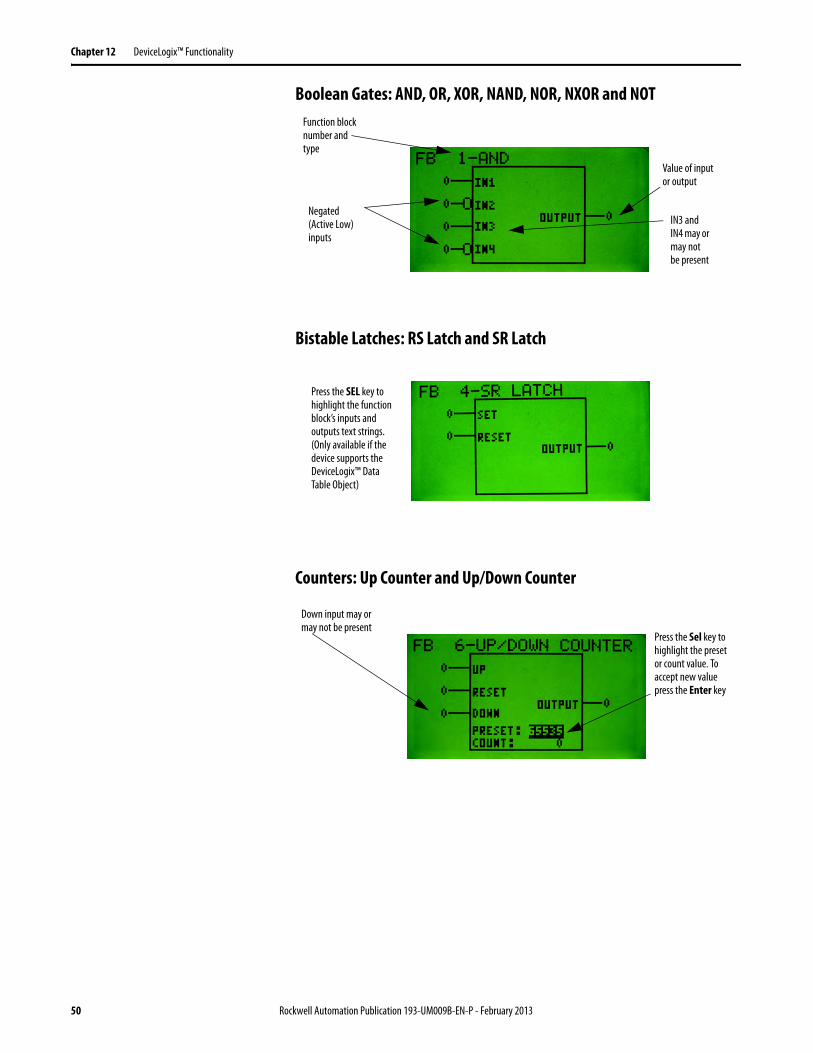
Boolean Gates: AND, OR, XOR, NAND, NOR, NXOR and NOT
Bistable Latches: RS Latch and SR Latch
Counters: Up Counter and Up/Down Counter
IN3 and IN4 may or may not be present
Value of input or output
Function block number and type
Negated (Active Low) inputs
Press the SEL key to highlight the function block’s inputs and outputs text strings. (Only available if the device supports the DeviceLogix™ Data Table Object)
Down input may or may not be present
Press the Sel key to highlight the preset or count value. To accept new value press the Enter key
50 Rockwell Automation Publication 193-UM009B-EN-P - February 2013
DeviceLogix™ Functionality Chapter 12
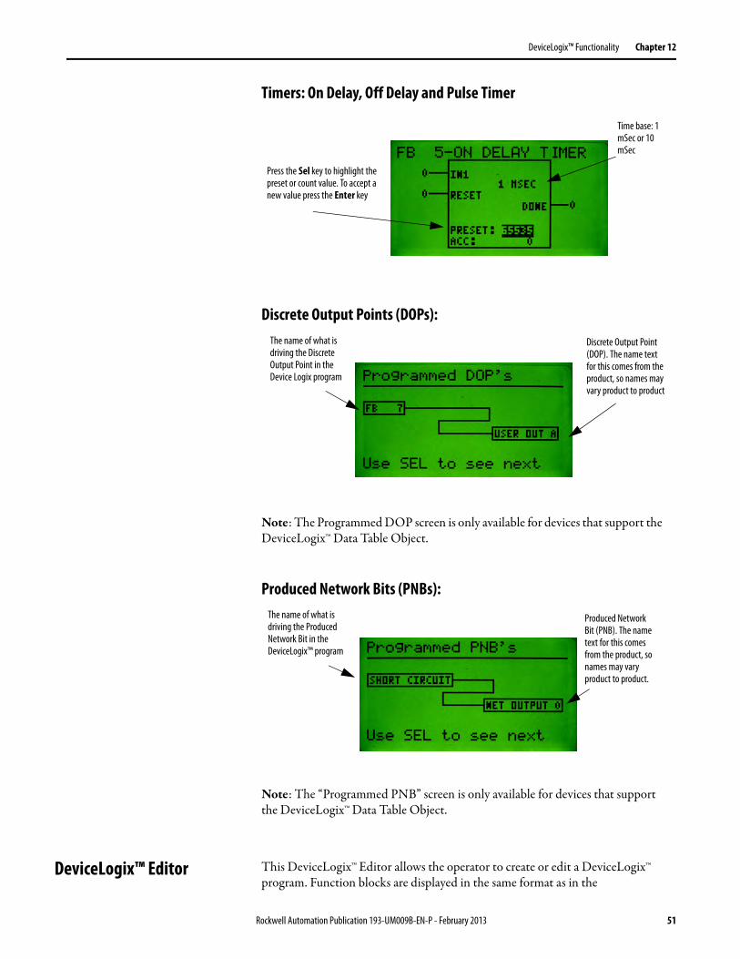
Timers: On Delay, Off Delay and Pulse Timer
Discrete Output Points (DOPs):
Note: The Programmed DOP screen is only available for devices that support the DeviceLogix™ Data Table Object.
Produced Network Bits (PNBs):
Note: The “Programmed PNB” screen is only available for devices that support the DeviceLogix™ Data Table Object.
DeviceLogix™ Editor This DeviceLogix™ Editor allows the operator to create or edit a DeviceLogix™ program. Function blocks are displayed in the same format as in the
Time base: 1 mSec or 10 mSec
Press the Sel key to highlight the preset or count value. To accept a new value press the Enter key
Discrete Output Point (DOP). The name text for this comes from the product, so names may vary product to product
The name of what is driving the Discrete Output Point in the Device Logix program
Produced Network Bit (PNB). The name text for this comes from the product, so names may vary product to product.
The name of what is driving the Produced Network Bit in the DeviceLogix™ program
Rockwell Automation Publication 193-UM009B-EN-P - February 2013 51

Chapter 12 DeviceLogix™ Functionality
DeviceLogix™ Monitor. To create, edit or delete a program element, use the INC/DEC keys to navigate to the item to create/edit and then press the Enter key. To edit one of the inputs of a function block, use the SEL key to highlight the input and then press the Enter key. To invoke the DeviceLogix™ Editor, select the Edit item in the DeviceLogix™ Choices Menu and press the Enter key.
Creating a New Function Block
Consider the following example of creating a new AND gate function block. First, invoke the Device Logix editor. One of two displays will appear, either a display of a function block or a screen displaying “No FB’s programmed”. At this point press the Enter key and the following screen appears:
Press the Enter key to create a new function block. Now that a new function block has been created, the type of function block must be selected. The following screen will appear:
Use the INC/DEC keys to select the new function block type. Press the Enter key when the desired function block type is selected. The following screen will appear (the Boolean type screen is shown below. Other similar screens appear for other function bock types.)
The Edit and Delete choices are only present if there are function blocks already programmed
52 Rockwell Automation Publication 193-UM009B-EN-P - February 2013
DeviceLogix™ Functionality Chapter 12
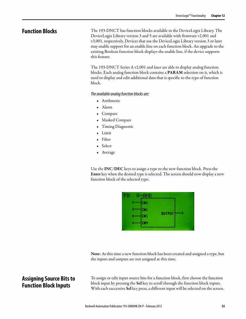
Function Blocks The 193-DNCT has function blocks available in the DeviceLogix Library. The DeviceLogix Library version 3 and 5 are available with firmware v2.001 and v3.001, respectively. Devices that use the DeviceLogix Library version 3 or later may enable support for an enable line on each function block. An upgrade to the existing Boolean function block displays the enable line, if the device supports this feature.
The 193-DNCT Series A v2.001 and later are able to display analog function blocks. Each analog function block contains a PARAM selection on it, which is used to display and edit additional data that is specific to the type of function block.
The available analog function blocks are:• Arithmetic• Alarm• Compare• Masked Compare• Timing Diagnostic• Limit• Filter• Select• Average
Use the INC/DEC keys to assign a type to the new function block. Press the Enter key when the desired type is selected. The screen should now display a new function block of the selected type:
Note: At this time a new function block has been created and assigned a type, but the inputs and outputs are not assigned at this time.
Assigning Source Bits to Function Block Inputs
To assign or edit input source bits for a function block, first choose the function block input by pressing the Sel key to scroll through the function block inputs. With each successive Sel key press, a different input will be selected on the screen.
Rockwell Automation Publication 193-UM009B-EN-P - February 2013 53
Chapter 12 DeviceLogix™ Functionality
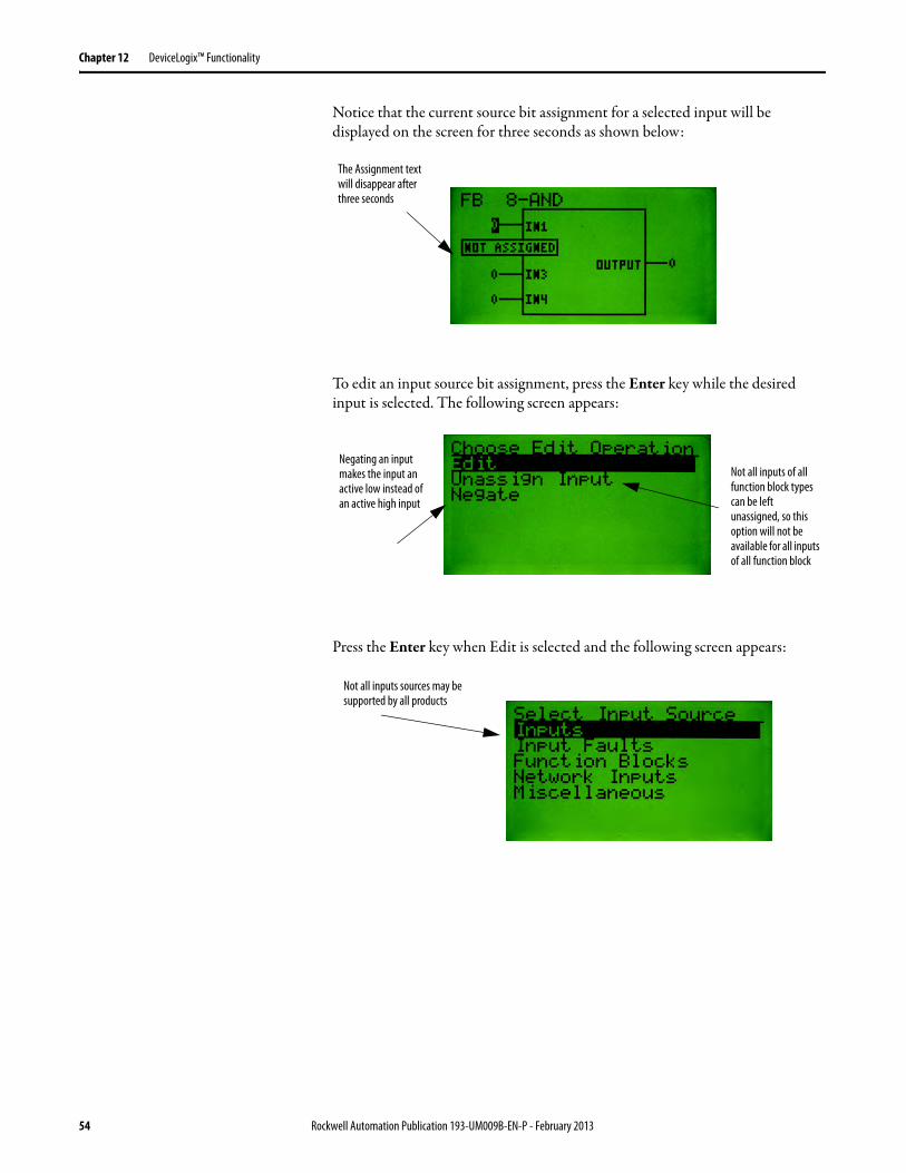
Notice that the current source bit assignment for a selected input will be displayed on the screen for three seconds as shown below:
To edit an input source bit assignment, press the Enter key while the desired input is selected. The following screen appears:
Press the Enter key when Edit is selected and the following screen appears:
The Assignment text will disappear after three seconds
Negating an input makes the input an active low instead of an active high input
Not all inputs of all function block types can be left unassigned, so this option will not be available for all inputs of all function block
Not all inputs sources may be supported by all products
54 Rockwell Automation Publication 193-UM009B-EN-P - February 2013
Chapter 13
Discrete I/O Status
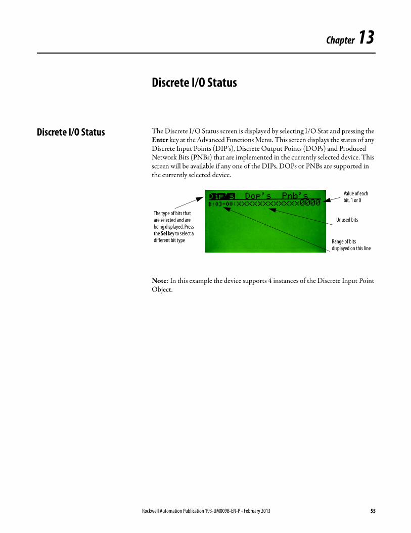
Discrete I/O Status The Discrete I/O Status screen is displayed by selecting I/O Stat and pressing the Enter key at the Advanced Functions Menu. This screen displays the status of any Discrete Input Points (DIP’s), Discrete Output Points (DOPs) and Produced Network Bits (PNBs) that are implemented in the currently selected device. This screen will be available if any one of the DIPs, DOPs or PNBs are supported in the currently selected device.
Note: In this example the device supports 4 instances of the Discrete Input Point Object.
The type of bits that are selected and are being displayed. Press the Sel key to select a different bit type
Unused bits
Value of each bit, 1 or 0
Range of bits displayed on this line
Rockwell Automation Publication 193-UM009B-EN-P - February 2013 55

Chapter 13 Discrete I/O Status
Notes:
56 Rockwell Automation Publication 193-UM009B-EN-P - February 2013

Chapter 14
Zone Interlock Protocol (ZIP)
Zone Interlock Protocol (ZIP) The Zone Interlock Protocol (ZIP) menu is available for devices that support the DeviceNet™ Zone Interlock Protocol Object. The Zone Interlock Protocol provides a way for devices to share I/O message data directly, and the data that is consumed from other devices can then be used in a DeviceLogix™ program. The ZIP Choices Menu is displayed by selecting ZIP and pressing the Enter key at the Advanced Functions Menu. The following menu choices are available to edit and monitor the ZIP configuration:
ZIP Consumed This screen allows the operator to configure the ZIP data that the device is going to consume. Configuring ZIP Consumed data consists of mapping I/O data from other nodes or zones on the network to the device’s internal ZIP Data Table (the ZIP Data Table is where a DeviceLogix™ program accesses ZIP data). Devices that support ZIP can define the number of zones from which they can consume at one time. In this manual it is assumed that the device can consume data from up to four zones at one time. The size of the internal ZIP data table is device specific. In this manual it is also assumed that the internal ZIP data table is eight bytes long.
The following screen shows a device with no ZIP I/O data configured or mapped:
Zone number (1…4) that is associated with data currently highlighted. Note: x = no zone is associated at this time
The Node Number of the device whose I/O data is mapped in this zone
This is the internal zip data table. B:00-07 indicates that we are viewing data table bytes 0…7 (B:08-15 would be displayed on the next line if the data table was 16 bytes long). Each XX represents one byte in the data table. The XX will display the Devices Node Number whose I/O data is mapped to that byte in the ZIP data table.
Number of Zones left in this device that are not
Rockwell Automation Publication 193-UM009B-EN-P - February 2013 57
Chapter 14 Zone Interlock Protocol (ZIP)
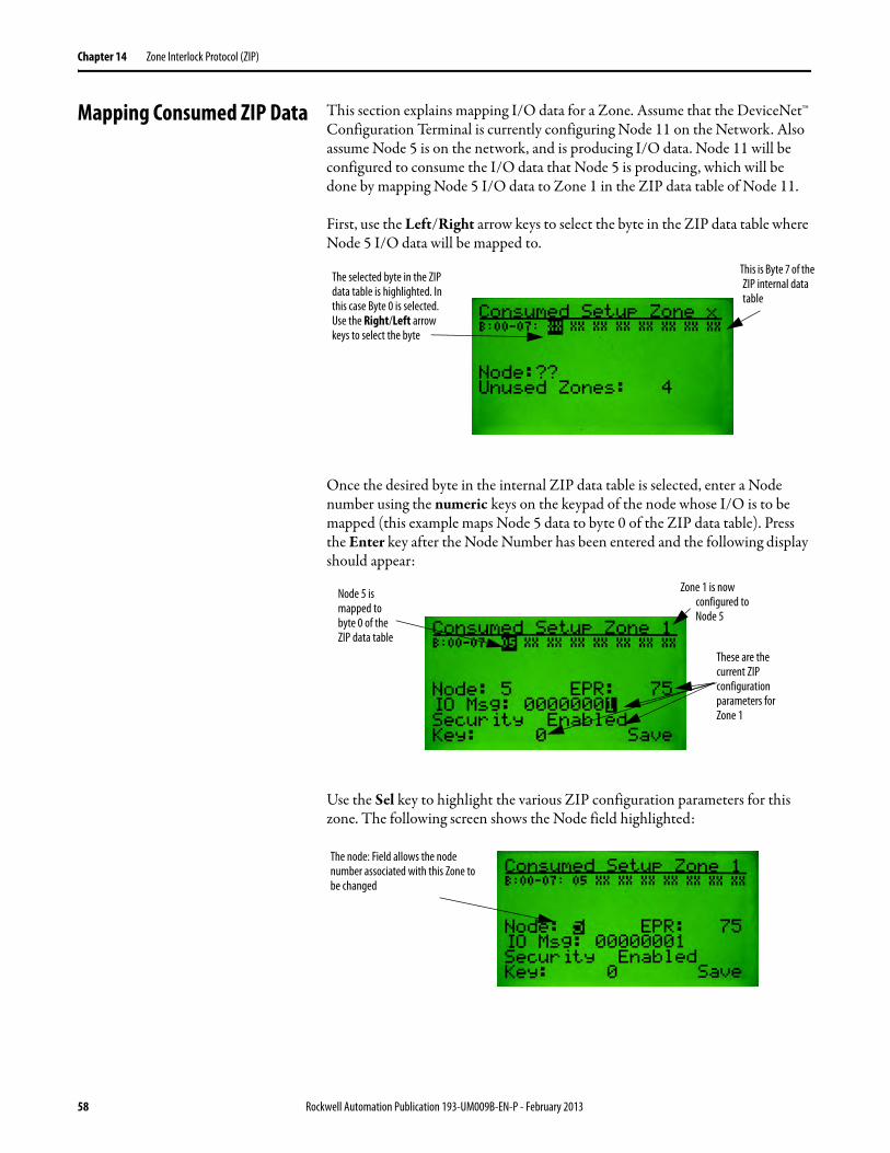
Mapping Consumed ZIP Data This section explains mapping I/O data for a Zone. Assume that the DeviceNet™ Configuration Terminal is currently configuring Node 11 on the Network. Also assume Node 5 is on the network, and is producing I/O data. Node 11 will be configured to consume the I/O data that Node 5 is producing, which will be done by mapping Node 5 I/O data to Zone 1 in the ZIP data table of Node 11.
First, use the Left/Right arrow keys to select the byte in the ZIP data table where Node 5 I/O data will be mapped to.
Once the desired byte in the internal ZIP data table is selected, enter a Node number using the numeric keys on the keypad of the node whose I/O is to be mapped (this example maps Node 5 data to byte 0 of the ZIP data table). Press the Enter key after the Node Number has been entered and the following display should appear:
Use the Sel key to highlight the various ZIP configuration parameters for this zone. The following screen shows the Node field highlighted:
This is Byte 7 of the ZIP internal data table
The selected byte in the ZIP data table is highlighted. In this case Byte 0 is selected. Use the Right/Left arrow keys to select the byte
Node 5 is mapped to byte 0 of the ZIP data table
These are the current ZIP configuration parameters for Zone 1
Zone 1 is now configured to Node 5
The node: Field allows the node number associated with this Zone to be changed
58 Rockwell Automation Publication 193-UM009B-EN-P - February 2013

Zone Interlock Protocol (ZIP) Chapter 14
The following screen shows the EPR (Expected Packet Rate) field highlighted:
The following screen shows the IO Msg field highlighted:
Note: The IO Msg field may also be referred to as the Zone Mask field.
The following screen shows that byte 0 and byte 2 of the I/O data from node 5 are mapped to the ZIP data table. To accomplish this the IO Msg field must be mapped to the value of “00000101”. Press the Enter key to edit the IO Msg field value. After editing, the value the screen will appear as follows:
EPR (Expected Packet Rate) allows the expected packet rate of the I/O data from node (Node 5) to be changed. This value is in milliseconds.
The “IO Msg:” field allows the choice of which bytes of the I/O data from node 5 are going to be mapped to the ZIP data table. Each bit in the IO Msg field maps or un-maps a byte of the I/O data from node 5. The value 1 means map this byte of I/O data. In this example, only byte 0 of the I/O data from node 5 is being mapped.
This 1 maps” byte 2 of the IO data from node 5
Two bytes of I/O data from node 5 are now mapped to the internal ZIP data table
This 1 maps byte 0 of the IO data from node 5
Rockwell Automation Publication 193-UM009B-EN-P - February 2013 59
Chapter 14 Zone Interlock Protocol (ZIP)
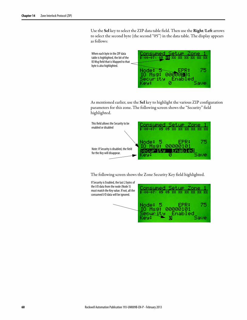
Use the Sel key to select the ZIP data table field. Then use the Right/Left arrows to select the second byte (the second “05”) in the data table. The display appears as follows:
As mentioned earlier, use the Sel key to highlight the various ZIP configuration parameters for this zone. The following screen shows the “Security” field highlighted.
The following screen shows the Zone Security Key field highlighted.
When each byte in the ZIP data table is highlighted, the bit of the IO Msg field that is Mapped to that byte is also highlighted.
Note: If Security is disabled, the field for the Key will disappear.
This field allows the Security to be enabled or disabled
If Security is Enabled, the last 2 bytes of the I/O data from the node (Node 5) must match the Key value. If not, all the consumed I/O data will be ignored.
60 Rockwell Automation Publication 193-UM009B-EN-P - February 2013
Zone Interlock Protocol (ZIP) Chapter 14
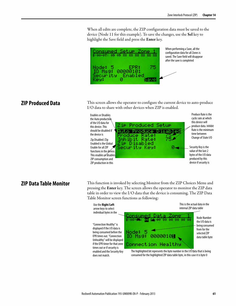
When all edits are complete, the ZIP configuration data must be saved to the device (Node 11 for this example). To save the changes, use the Sel key to highlight the Save field and press the Enter key.
ZIP Produced Data This screen allows the operator to configure the current device to auto-produce I/O data to share with other devices when ZIP is enabled.
ZIP Data Table Monitor This function is invoked by selecting Monitor from the ZIP Choices Menu and pressing the Enter key. The screen allows the operator to monitor the ZIP data table in order to view the I/O data that the device is consuming. The ZIP Data Table Monitor screen functions as following:
When performing a Save, all the configuration data for all Zones is saved. The Save field will disappear after the save is completed
Security Key is the value of the last 2 bytes of the I/O data produced by this device if security is
Produce Rate is the cyclic rate at which this device will produce data. Inhibit Rate is the minimum time between Change of State I/O
Zip Disabled /Zip Enabled is the Global Enable for all ZIP functions in the device. This enables or disables ZIP consumption and ZIP production in this
Enables or Disables the Auto production of the I/O data for this device. This should be disabled if the device is
“Connection Healthy” is displayed if the I/O data is being consumed before the EPR times out. “Connection Unhealthy” will be displayed if the EPR timer for that zone times out or if security is enabled and the Security Key does not match.
Node Number the I/O data is being consumed from for the selected ZIP data table byte
This is the actual data in the internal ZIP data table
Use the Right/Left arrow keys to select individual bytes in the
The highlighted bit represents the byte number in the I/O data that is being consumed for the highlighted ZIP data table byte, in this case it is byte 0
Rockwell Automation Publication 193-UM009B-EN-P - February 2013 61
Chapter 14 Zone Interlock Protocol (ZIP)
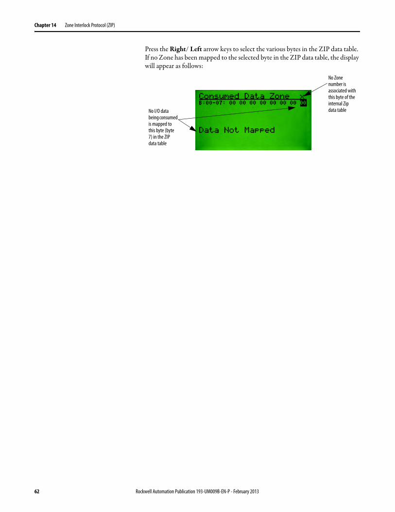
Press the Right/ Left arrow keys to select the various bytes in the ZIP data table. If no Zone has been mapped to the selected byte in the ZIP data table, the display will appear as follows:
No I/O data being consumed is mapped to this byte (byte 7) in the ZIP data table
No Zone number is associated with this byte of the internal Zip data table
62 Rockwell Automation Publication 193-UM009B-EN-P - February 2013
Chapter 15
DeviceNet™ Scanner Menu
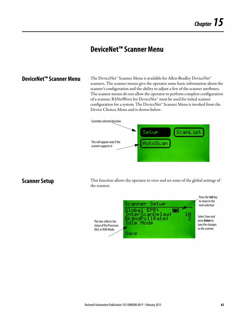
DeviceNet™ Scanner Menu The DeviceNet™ Scanner Menu is available for Allen-Bradley DeviceNet™ scanners. The scanner menus give the operator some basic information about the scanner’s configuration and the ability to adjust a few of the scanner attributes. The scanner menus do not allow the operator to perform complete configuration of a scanner. RSNetWorx for DeviceNet™ must be used for initial scanner configuration for a system. The DeviceNet™ Scanner Menu is invoked from the Device Choices Menu and is shown below:
Scanner Setup This function allows the operator to view and set some of the global settings of the scanner.
Currently selected function
This will appear only if the scanner supports it
This line reflects the status of the Processor, IDLE or RUN Mode.
Press the Sel key to move to the next selection
Select Save and press Enter to save the changes to the scanner.
Rockwell Automation Publication 193-UM009B-EN-P - February 2013 63
Chapter 15 DeviceNet™ Scanner Menu
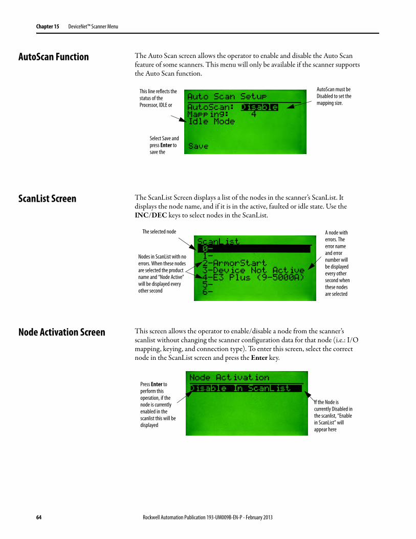
AutoScan Function The Auto Scan screen allows the operator to enable and disable the Auto Scan feature of some scanners. This menu will only be available if the scanner supports the Auto Scan function.
ScanList Screen The ScanList Screen displays a list of the nodes in the scanner’s ScanList. It displays the node name, and if it is in the active, faulted or idle state. Use the INC/DEC keys to select nodes in the ScanList.
Node Activation Screen This screen allows the operator to enable/disable a node from the scanner’s scanlist without changing the scanner configuration data for that node (i.e.: I/O mapping, keying, and connection type). To enter this screen, select the correct node in the ScanList screen and press the Enter key.
Select Save and press Enter to save the
This line reflects the status of the Processor, IDLE or
AutoScan must be Disabled to set the mapping size.
A node with errors. The error name and error number will be displayed every other second when these nodes are selected
The selected node
Nodes in ScanList with no errors. When these nodes are selected the product name and “Node Active” will be displayed every other second
Press Enter to perform this operation, if the node is currently enabled in the scanlist this will be displayed
If the Node is currently Disabled in the scanlist, “Enable in ScanList” will appear here
64 Rockwell Automation Publication 193-UM009B-EN-P - February 2013

Chapter 16
Terminal Choices Menu
Terminal Choices Menu The Terminal Choices Menu is only displayed when the device selected in the Who Menu is This DeviceNet™ HIM. It is displayed instead of the Device Choices Menu.
Version Menu This screen is displays the revision of the DeviceNet™ Configuration Terminal firmware.
Offline Connection Set This function allows the operator to perform Faulted Address Recovery (FAR) for nodes that fail the Duplicate MAC ID test. To get to this function select Offline from the Terminal Choices Menu. The first screen to appear will be the Offline Who Screen, which will request ownership of the Offline Connection Set. When ownership is obtained, it will search for faulted nodes. If any faulted nodes are found, they will be displayed.
Once ownership is obtained, this will change to “Checking for Devices”
Rockwell Automation Publication 193-UM009B-EN-P - February 2013 65
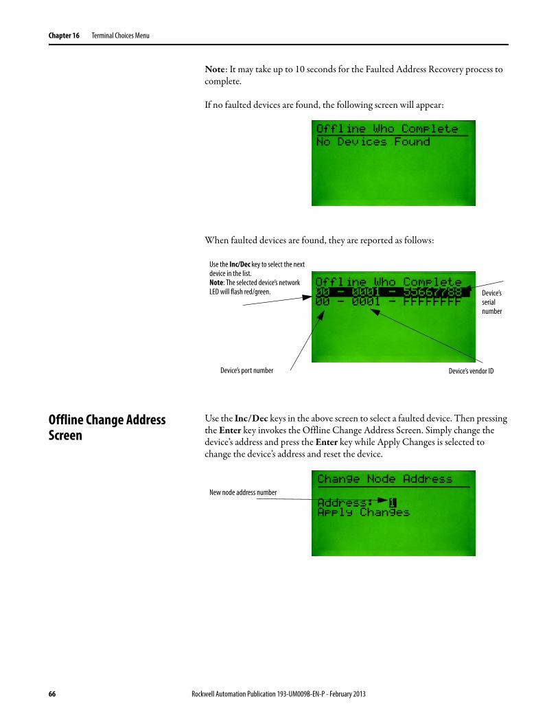
Chapter 16 Terminal Choices Menu
Note: It may take up to 10 seconds for the Faulted Address Recovery process to complete.
If no faulted devices are found, the following screen will appear:
When faulted devices are found, they are reported as follows:
Offline Change Address Screen
Use the Inc/Dec keys in the above screen to select a faulted device. Then pressing the Enter key invokes the Offline Change Address Screen. Simply change the device’s address and press the Enter key while Apply Changes is selected to change the device’s address and reset the device.
Use the Inc/Dec key to select the next device in the list.Note: The selected device’s network LED will flash red/green. Device’s
serial number
Device’s port number Device’s vendor ID
New node address number
66 Rockwell Automation Publication 193-UM009B-EN-P - February 2013
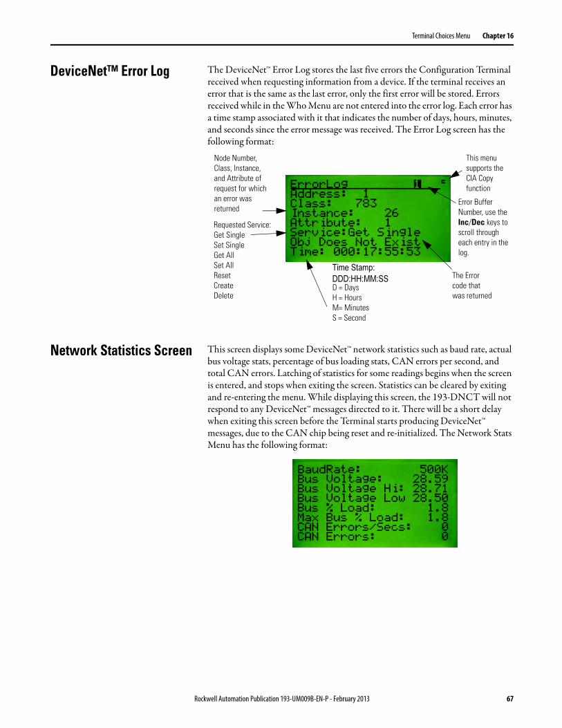
Terminal Choices Menu Chapter 16
DeviceNet™ Error Log The DeviceNet™ Error Log stores the last five errors the Configuration Terminal received when requesting information from a device. If the terminal receives an error that is the same as the last error, only the first error will be stored. Errors received while in the Who Menu are not entered into the error log. Each error has a time stamp associated with it that indicates the number of days, hours, minutes, and seconds since the error message was received. The Error Log screen has the following format:
Network Statistics Screen This screen displays some DeviceNet™ network statistics such as baud rate, actual bus voltage stats, percentage of bus loading stats, CAN errors per second, and total CAN errors. Latching of statistics for some readings begins when the screen is entered, and stops when exiting the screen. Statistics can be cleared by exiting and re-entering the menu. While displaying this screen, the 193-DNCT will not respond to any DeviceNet™ messages directed to it. There will be a short delay when exiting this screen before the Terminal starts producing DeviceNet™ messages, due to the CAN chip being reset and re-initialized. The Network Stats Menu has the following format:
This menu supports the CIA Copy function
Error Buffer Number, use the Inc/Dec keys to scroll through each entry in the log.
Node Number, Class, Instance, and Attribute of request for which an error was returned
Requested Service: Get Single Set Single Get All Set All Reset Create Delete
The Error code that was returned
Time Stamp:
DDD:HH:MM:SS
D = Days H = Hours M= Minutes S = Second
Rockwell Automation Publication 193-UM009B-EN-P - February 2013 67

Chapter 16 Terminal Choices Menu
Notes:
68 Rockwell Automation Publication 193-UM009B-EN-P - February 2013
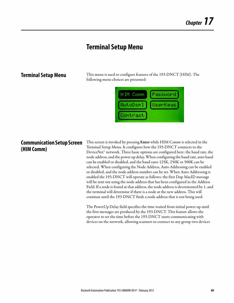
Chapter 17
Terminal Setup Menu
Terminal Setup Menu This menu is used to configure features of the 193-DNCT (HIM). The following menu choices are presented:
Communication Setup Screen (HIM Comm)
This screen is invoked by pressing Enter while HIM Comm is selected in the Terminal Setup Menu. It configures how the 193-DNCT connects to the DeviceNet™ network. Three basic options are configured here: the baud rate, the node address, and the power up delay. When configuring the baud rate, auto baud can be enabled or disabled, and the baud rates 125K, 250K or 500K can be selected. When configuring the Node Address, Auto Addressing can be enabled or disabled, and the node address number can be set. When Auto Addressing is enabled the 193-DNCT will operate as follows: the first Dup MacID message will be sent out using the node address that has been configured in the Address Field. If a node is found at that address, the node address is decremented by 1, and the terminal will determine if there is a node at the new address. This will continue until the 193-DNCT finds a node address that is not being used.
The PowerUp Delay field specifies the time waited from initial power up until the first messages are produced by the 193-DNCT. This feature allows the operator to set the time before the 193-DNCT starts communicating with devices on the network, allowing scanners to connect to any group two devices
Rockwell Automation Publication 193-UM009B-EN-P - February 2013 69

Chapter 17 Terminal Setup Menu
and start proxying. It also allows all devices to come online before AutoAddressing.
Password Menu The 193-DNCT has five passwords: one primary (master) password and four secondary passwords. When the primary password has been configured and correctly entered the operator will gain full access to all features in 193-DNCT. The secondary passwords can be configured to limit the features that are associated with that password, so when a secondary password is entered, the operator will only gain access to limited features in the 193-DNCT. The following choices may appear when the Password selection is chosen from the HIM Setup Menu:
This is the Baud Rate that is used if AutoBaud is disabled
PowerUp Delay (in seconds)
Node Number of the 193-DNCT if AutoAddress is disabled. If AutoAddress is enabled, this is the starting Node Number
Must have the primary password set for this selection to appear
Must have at least one password logged in for this selection to appear
70 Rockwell Automation Publication 193-UM009B-EN-P - February 2013
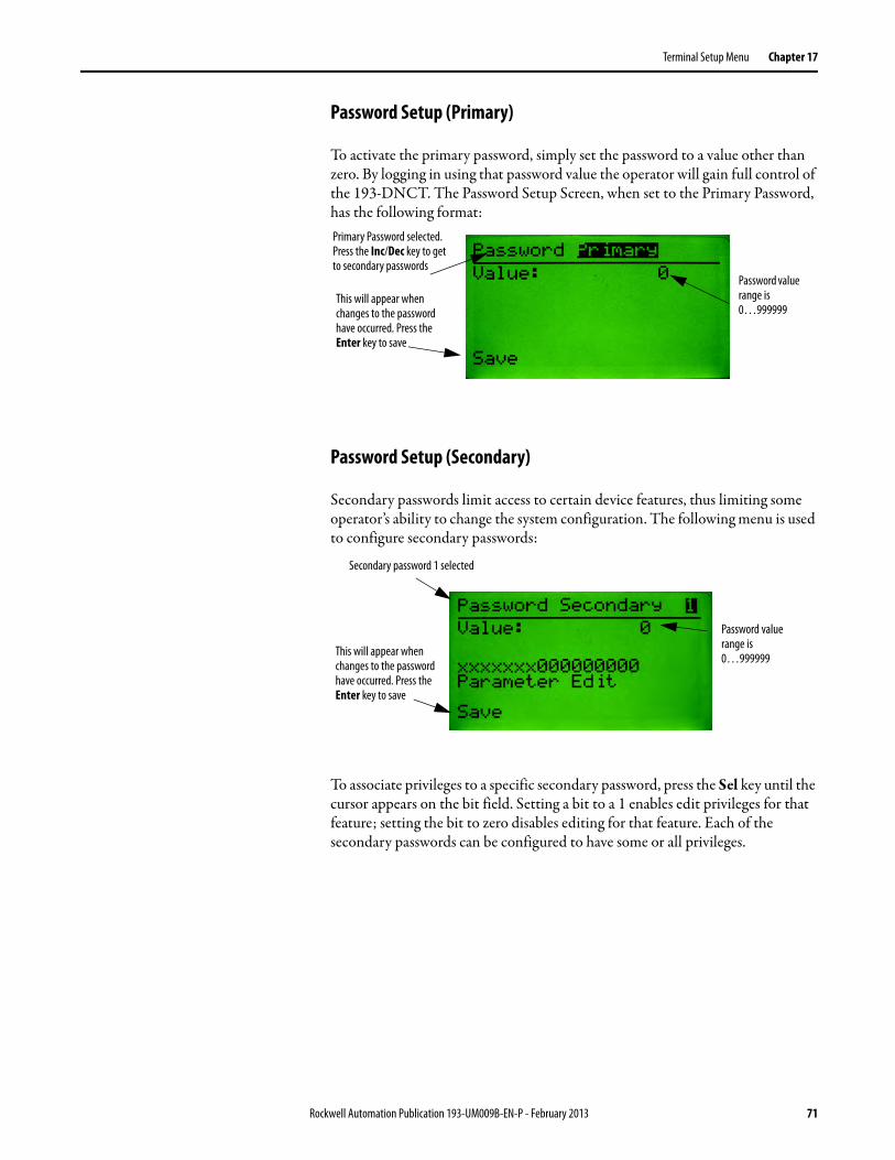
Terminal Setup Menu Chapter 17
Password Setup (Primary)
To activate the primary password, simply set the password to a value other than zero. By logging in using that password value the operator will gain full control of the 193-DNCT. The Password Setup Screen, when set to the Primary Password, has the following format:
Password Setup (Secondary)
Secondary passwords limit access to certain device features, thus limiting some operator’s ability to change the system configuration. The following menu is used to configure secondary passwords:
To associate privileges to a specific secondary password, press the Sel key until the cursor appears on the bit field. Setting a bit to a 1 enables edit privileges for that feature; setting the bit to zero disables editing for that feature. Each of the secondary passwords can be configured to have some or all privileges.
Password value range is 0…999999
Primary Password selected. Press the Inc/Dec key to get to secondary passwords
This will appear when changes to the password have occurred. Press the Enter key to save
Password value range is 0…999999
Secondary password 1 selected
This will appear when changes to the password have occurred. Press the Enter key to save
Rockwell Automation Publication 193-UM009B-EN-P - February 2013 71
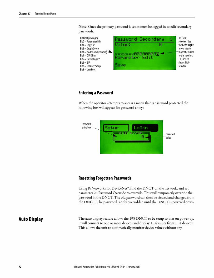
Chapter 17 Terminal Setup Menu
Note: Once the primary password is set, it must be logged in to edit secondary passwords.
Entering a Password
When the operator attempts to access a menu that is password protected the following box will appear for password entry:
Resetting Forgotten Passwords
Using RsNetworks for DeviceNet™, find the DNCT on the network, and set parameter 2 - Password Override to override. This will temporarily override the password in the DNCT. The old password can then be viewed and changed from the DNCT. The password is only overridden until the DNCT is powered down.
Auto Display The auto display feature allows the 193-DNCT to be setup so that on power up, it will connect to one or more devices and display 1…4 values from 1…4 devices. This allows the unit to automatically monitor device values without any
Bit Field selected. Use the Left/Right arrow keys to move the cursor to the next bit. This screen shows bit 0 selected.
Bit Field privileges: Bit0 = Parameter Edit Bit1 = CopyCat Bit2 = Graph Setup Bit3 = Node Commissioning Bit4 = CIA Editor Bit5 = DeviceLogix™ Bit6 = ZIP Bit7 = Scanner Setup Bit8 = UserKeys
Password Value
Password entry box
72 Rockwell Automation Publication 193-UM009B-EN-P - February 2013
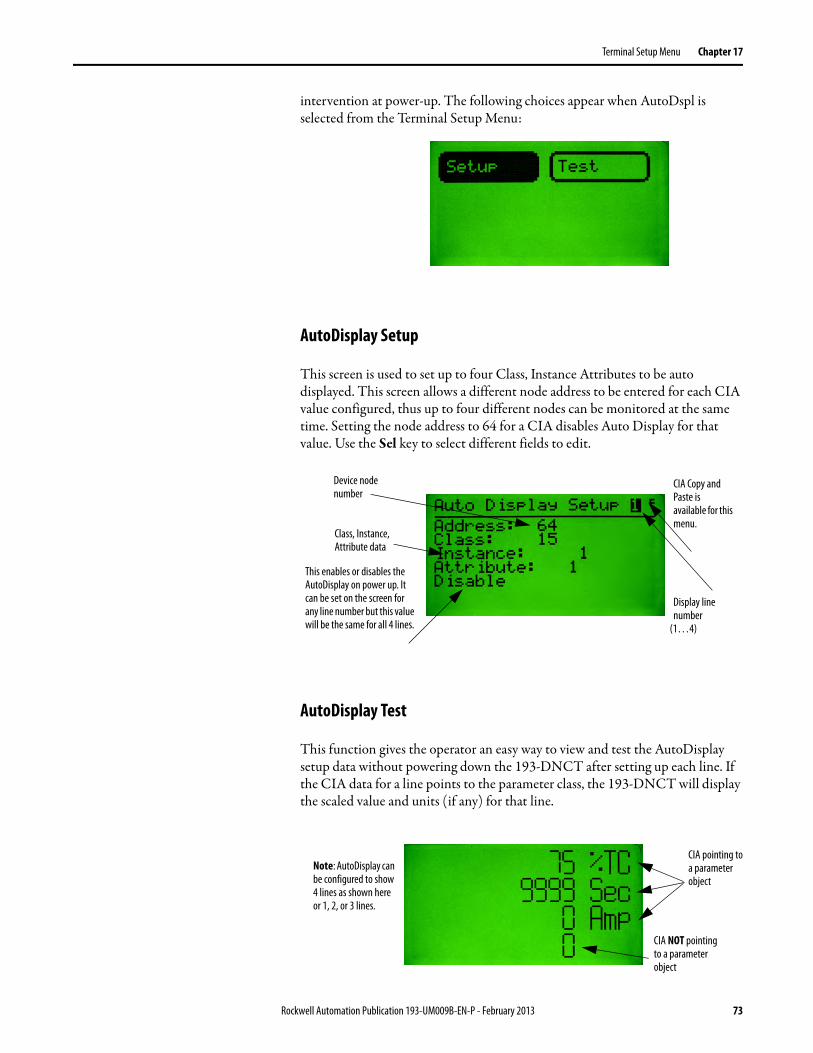
Terminal Setup Menu Chapter 17
intervention at power-up. The following choices appear when AutoDspl is selected from the Terminal Setup Menu:
AutoDisplay Setup
This screen is used to set up to four Class, Instance Attributes to be auto displayed. This screen allows a different node address to be entered for each CIA value configured, thus up to four different nodes can be monitored at the same time. Setting the node address to 64 for a CIA disables Auto Display for that value. Use the Sel key to select different fields to edit.
AutoDisplay Test
This function gives the operator an easy way to view and test the AutoDisplay setup data without powering down the 193-DNCT after setting up each line. If the CIA data for a line points to the parameter class, the 193-DNCT will display the scaled value and units (if any) for that line.
CIA Copy and Paste is available for this menu.
Device node number
Display line number
(1…4)
This enables or disables the AutoDisplay on power up. It can be set on the screen for any line number but this value will be the same for all 4 lines.
Class, Instance, Attribute data
CIA NOT pointing to a parameter object
CIA pointing to a parameter object
Note: AutoDisplay can be configured to show 4 lines as shown here or 1, 2, or 3 lines.
Rockwell Automation Publication 193-UM009B-EN-P - February 2013 73
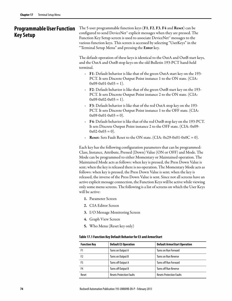
Chapter 17 Terminal Setup Menu
Programmable User Function Key Setup
The 5 user programmable function keys (F1, F2, F3, F4 and Reset) can be configured to send DeviceNet™ explicit messages when they are pressed. The Function Key Setup screen is used to associate DeviceNet™ messages to the various function keys. This screen is accessed by selecting “UserKeys” in the “Terminal Setup Menu” and pressing the Enter key.
The default operation of these keys is identical to the OutA and OutB start keys, and the OutA and OutB stop keys on the old Bulletin 193-PCT hand-held terminal.
· F1: Default behavior is like that of the green OutA start key on the 193-PCT. It sets Discrete Output Point instance 1 to the ON state. (CIA: 0x09-0x01-0x03 = 1).
· F2: Default behavior is like that of the green OutB start key on the 193-PCT. It sets Discrete Output Point instance 2 to the ON state. (CIA: 0x09-0x02-0x03 = 1).
· F3: Default behavior is like that of the red OutA stop key on the 193-PCT. It sets Discrete Output Point instance 1 to the OFF state. (CIA: 0x09-0x01-0x03 = 0).
· F4: Default behavior is like that of the red OutB stop key on the 193-PCT. It sets Discrete Output Point instance 2 to the OFF state. (CIA: 0x09-0x02-0x03 = 0).
· Reset: Sets Fault Reset to the ON state. (CIA: 0x29-0x01-0x0C = 0).
Each key has the following configuration parameters that can be programmed: Class, Instance, Attribute, Pressed (Down) Value (ON or OFF) and Mode. The Mode can be programmed to either Momentary or Maintained operation. The Maintained Mode acts as follows: when key is pressed, the Press Down Value is sent; when the key is released there is no operation. The Momentary Mode acts as follows: when key is pressed, the Press Down Value is sent; when the key is released, the inverse of the Press Down Value is sent. Since not all screens have an active explicit message connection, the Function Keys will be active while viewing only some menu screens. The following is a list of screens on which the User Keys will be active:
1. Parameter Screen
2. CIA Editor Screen
3. I/O Message Monitoring Screen
4. Graph View Screen
5. Who Menu (Reset key only)
Table 17.1 Function Key Default Behavior for E3 and ArmorStart
Function Key Default E3 Operation Default ArmorStart Operation
F1 Turns on Output A Turns on Run Forward
F2 Turns on Output B Turns on Run Reverse
F3 Turns off Output A Turns off Run Forward
F4 Turns off Output B Turns off Run Reverse
Reset Resets Protection Faults Resets Protection Faults
74 Rockwell Automation Publication 193-UM009B-EN-P - February 2013

Terminal Setup Menu Chapter 17
Function Key Setup Screen
LCD Contrast This screen is used to change the contrast of the 193-DNCT LCD. The Inc/Dec keys are used to increase or decrease the contrast of the LCD.
Current key (F1) being configured. Press Inc/Dec to change keys
CIA Copy and Paste is available for this menu
Class, Instance, Attribute Information. Values
Value sent when the key is pressed, ON (1) or OFF (0)
Save will appear after changing the settings for any key, Pressing Enter will save the information for all the keys
Mode of key, Momentary or Maintained
Class, Instance, Attribute Information. Values are entered in Hexadecimal.
CIA Copy and Paste is available for this menu
Press Inc/Dec from the F4 setup screen to get to the Reset key setup
The default for the Reset key is the Clear Fault attribute of the Control Supervisor Object
Sample text to view when adjusting the contrast This bar graph
indicates the LCD’s contrast setting, 0…100%
Rockwell Automation Publication 193-UM009B-EN-P - February 2013 75

Chapter 17 Terminal Setup Menu
Notes:
76 Rockwell Automation Publication 193-UM009B-EN-P - February 2013
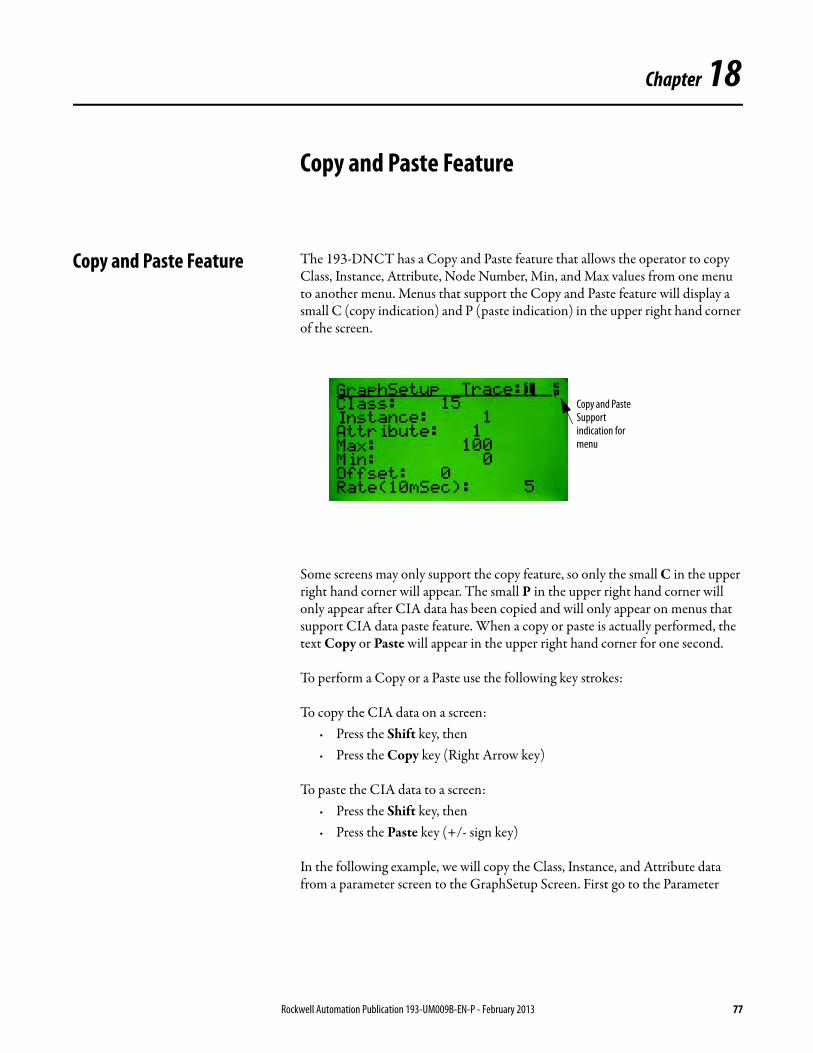
Chapter 18
Copy and Paste Feature
Copy and Paste Feature The 193-DNCT has a Copy and Paste feature that allows the operator to copy Class, Instance, Attribute, Node Number, Min, and Max values from one menu to another menu. Menus that support the Copy and Paste feature will display a small C (copy indication) and P (paste indication) in the upper right hand corner of the screen.
Some screens may only support the copy feature, so only the small C in the upper right hand corner will appear. The small P in the upper right hand corner will only appear after CIA data has been copied and will only appear on menus that support CIA data paste feature. When a copy or paste is actually performed, the text Copy or Paste will appear in the upper right hand corner for one second.
To perform a Copy or a Paste use the following key strokes:
To copy the CIA data on a screen:· Press the Shift key, then · Press the Copy key (Right Arrow key)
To paste the CIA data to a screen:· Press the Shift key, then · Press the Paste key (+/- sign key)
In the following example, we will copy the Class, Instance, and Attribute data from a parameter screen to the GraphSetup Screen. First go to the Parameter
Copy and Paste Support indication for menu
Rockwell Automation Publication 193-UM009B-EN-P - February 2013 77
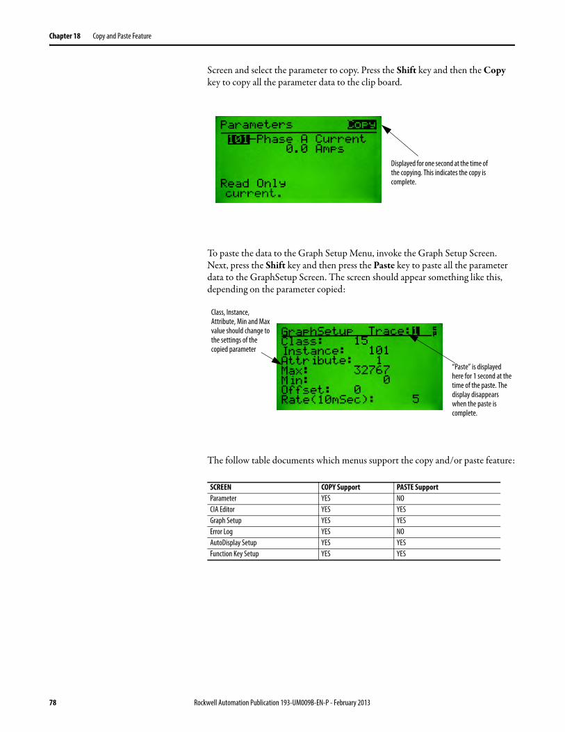
Chapter 18 Copy and Paste Feature
Screen and select the parameter to copy. Press the Shift key and then the Copy key to copy all the parameter data to the clip board.
To paste the data to the Graph Setup Menu, invoke the Graph Setup Screen. Next, press the Shift key and then press the Paste key to paste all the parameter data to the GraphSetup Screen. The screen should appear something like this, depending on the parameter copied:
The follow table documents which menus support the copy and/or paste feature:
SCREEN COPY Support PASTE SupportParameter YES NOCIA Editor YES YESGraph Setup YES YESError Log YES NOAutoDisplay Setup YES YESFunction Key Setup YES YES
Displayed for one second at the time of the copying. This indicates the copy is complete.
“Paste” is displayed here for 1 second at the time of the paste. The display disappears when the paste is complete.
Class, Instance, Attribute, Min and Max value should change to the settings of the copied parameter
78 Rockwell Automation Publication 193-UM009B-EN-P - February 2013
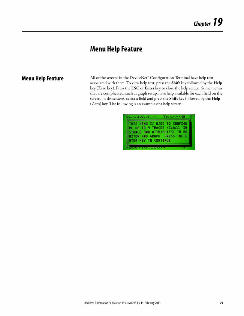
Chapter 19
Menu Help Feature
Menu Help Feature All of the screens in the DeviceNet™ Configuration Terminal have help text associated with them. To view help text, press the Shift key followed by the Help key (Zero key). Press the ESC or Enter key to close the help screen. Some menus that are complicated, such as graph setup, have help available for each field on the screen. In those cases, select a field and press the Shift key followed by the Help (Zero) key. The following is an example of a help screen:
Rockwell Automation Publication 193-UM009B-EN-P - February 2013 79

Chapter 19 Menu Help Feature
Notes:
80 Rockwell Automation Publication 193-UM009B-EN-P - February 2013
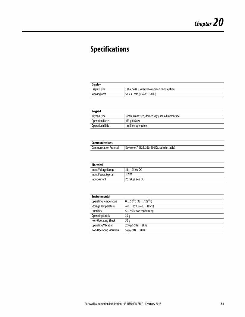
Chapter 20
Specifications
DisplayDisplay Type 128 x 64 LCD with yellow-green backlightingViewing Area 57 x 30 mm (2.24 x 1.18 in.)
KeypadKeypad Type Tactile embossed, domed keys, sealed membraneOperation Force 453 g (16 oz)Operational Life 1 million operations
CommunicationsCommunication Protocol DeviceNet™ (125, 250, 500 Kbaud selectable)
ElectricalInput Voltage Range 11…25.0V DCInput Power, typical 1.7 WInput current 70 mA @ 24V DC
EnvironmentalOperating Temperature 0…50°C (32…122°F)Storage Temperature -40…85°C (-40…185°F)Humidity 5…95% non condensingOperating Shock 30 gNon-Operating Shock 50 gOperating Vibration 2.5 g @ 5Hz…2kHzNon-Operating Vibration 5 g @ 5Hz…2kHz
Rockwell Automation Publication 193-UM009B-EN-P - February 2013 81
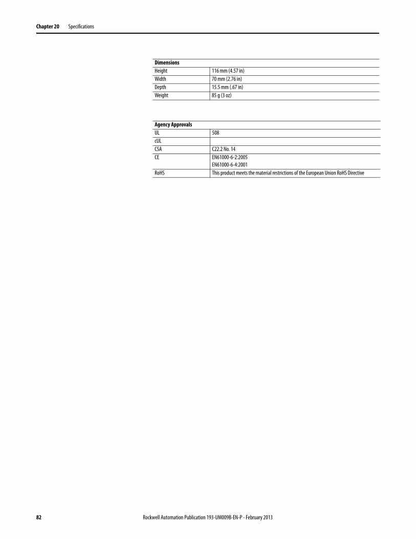
Chapter 20 Specifications
DimensionsHeight 116 mm (4.57 in)Width 70 mm (2.76 in)Depth 15.5 mm (.67 in)Weight 85 g (3 oz)
Agency ApprovalsUL 508cULCSA C22.2 No. 14CE EN61000-6-2:2005
EN61000-6-4:2001RoHS This product meets the material restrictions of the European Union RoHS Directive
82 Rockwell Automation Publication 193-UM009B-EN-P - February 2013
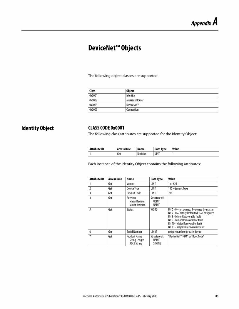
Appendix A
DeviceNet™ Objects
The following object classes are supported:
Identity Object CLASS CODE 0x0001The following class attributes are supported for the Identity Object:
Each instance of the Identity Object contains the following attributes:
Class Object0x0001 Identity0x0002 Message Router0x0003 DeviceNet™0x0005 Connection
Attribute ID Access Rule Name Data Type Value1 Get Revision UINT 1
Attribute ID Access Rule Name Data Type Value1 Get Vendor UINT 1 or 6252 Get Device Type UINT 115 - Generic Type3 Get Product Code UINT 2084 Get Revision
Major Revision Minor Revision
Structure of: USINT USINT
5 Get Status WORD Bit 0 - 0=not owned; 1=owned by master Bit 2 - 0=Factory Defaulted; 1=Configured Bit 8 - Minor Recoverable fault Bit 9 - Minor Unrecoverable fault Bit 10 - Major Recoverable fault Bit 11 - Major Unrecoverable fault
6 Get Serial Number UDINT unique number for each device7 Get Product Name
String Length ASCII String
Structure of: USINT STRING
“DeviceNet™ HIM” or “Boot Code”
Rockwell Automation Publication 193-UM009B-EN-P - February 2013 83
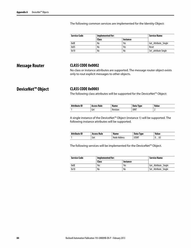
Appendix A DeviceNet™ Objects
The following common services are implemented for the Identity Object:
Message Router CLASS CODE 0x0002No class or instance attributes are supported. The message router object exists only to rout explicit messages to other objects.
DeviceNet™ Object CLASS CODE 0x0003The following class attributes will be supported for the DeviceNet™ Object:
A single instance of the DeviceNet™ Object (instance 1) will be supported. The following instance attributes will be supported.
The following services will be implemented for the DeviceNet™ Object.
Service Code Implemented for: Service NameClass Instance
0x0E No Yes Get_Attribute_Single0x05 No Yes Reset0x10 No No Set_attribute Single
Attribute ID Access Rule Name Data Type Value1 Get Revision UINT 2
Attribute ID Access Rule Name Data Type Value1 Get Node Address USINT 0…63
Service Code Implemented for: Service NameClass Instance
0x0E Yes Yes Get_Attribute_Single0x10 No No Set_Attribute_Single
84 Rockwell Automation Publication 193-UM009B-EN-P - February 2013
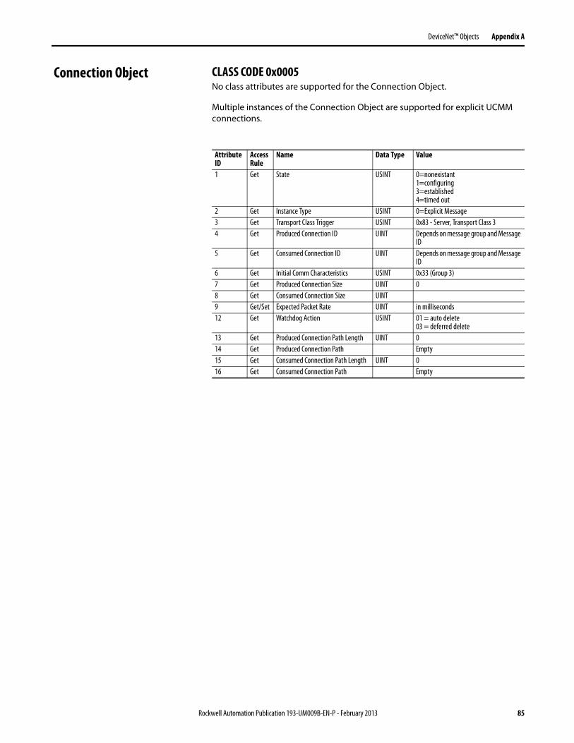
DeviceNet™ Objects Appendix A
Connection Object CLASS CODE 0x0005No class attributes are supported for the Connection Object.
Multiple instances of the Connection Object are supported for explicit UCMM connections.
Attribute ID
Access Rule
Name Data Type Value
1 Get State USINT 0=nonexistant 1=configuring 3=established 4=timed out
2 Get Instance Type USINT 0=Explicit Message3 Get Transport Class Trigger USINT 0x83 - Server, Transport Class 34 Get Produced Connection ID UINT Depends on message group and Message
ID5 Get Consumed Connection ID UINT Depends on message group and Message
ID6 Get Initial Comm Characteristics USINT 0x33 (Group 3)7 Get Produced Connection Size UINT 08 Get Consumed Connection Size UINT9 Get/Set Expected Packet Rate UINT in milliseconds12 Get Watchdog Action USINT 01 = auto delete
03 = deferred delete13 Get Produced Connection Path Length UINT 014 Get Produced Connection Path Empty15 Get Consumed Connection Path Length UINT 016 Get Consumed Connection Path Empty
Rockwell Automation Publication 193-UM009B-EN-P - February 2013 85

Appendix A DeviceNet™ Objects
Notes:
86 Rockwell Automation Publication 193-UM009B-EN-P - February 2013

Publication 193-UM009B-EN-P - February 2013 PN-40754-656-02Supersedes Publication 193-UM009A-EN-P - December 2006 Copyright © 2013 Rockwell Automation, Inc. All rights reserved. Printed in the U.S.A.
Rockwell Automation Support
Rockwell Automation provides technical information on the Web to assist you in using its products. At http://www.rockwellautomation.com/support, you can find technical manuals, technical and application notes, sample code and links to software service packs, and a MySupport feature that you can customize to make the best use of these tools. You can also visit our Knowledgebase at http://www.rockwellautomation.com/knowledgebase for FAQs, technical information, support chat and forums, software updates, and to sign up for product notification updates.
For an additional level of technical phone support for installation, configuration, and troubleshooting, we offer TechConnectSM support programs. For more information, contact your local distributor or Rockwell Automation representative, or visit http://www.rockwellautomation.com/support/.
Installation Assistance
If you experience a problem within the first 24 hours of installation, review the information that is contained in this manual. You can contact Customer Support for initial help in getting your product up and running.
New Product Satisfaction Return
Rockwell Automation tests all of its products to ensure that they are fully operational when shipped from the manufacturing facility. However, if your product is not functioning and needs to be returned, follow these procedures.
Documentation Feedback
Your comments will help us serve your documentation needs better. If you have any suggestions on how to improve this document, complete this form, publication RA-DU002, available at http://www.rockwellautomation.com/literature/.
United States or Canada 1.440.646.3434
Outside United States or Canada Use the Worldwide Locator at http://www.rockwellautomation.com/support/americas/phone_en.html, or contact your local Rockwell Automation representative.
United States Contact your distributor. You must provide a Customer Support case number (call the phone number above to obtain one) to your distributor to complete the return process.
Outside United States Please contact your local Rockwell Automation representative for the return procedure.