dfi302e - smar - first in fieldbus · dfi302 f4 fb devices wiring for power and h1 fieldbus is done...
TRANSCRIPT

FB D
EVIC
ES
2F
DFI302DFI302DFI302DFI302DFI302FIELDBUS UNIVERSAL BRIDGE
Features Integral part of SYSTEM302
Single integrated unit of interface, linking device, bridge,
controller, gateway, Fieldbus power supply and distributed I/O
subsystem.
Tight integration with intelligent devices and software from
multiple manufacturers due to use of open standards as FOUNDATIONTM
Fieldbus and OPC.
Connects to existing equipment through conventional I/O and
Modbus communication.
Full redundancy and fault isolation for high safety and
uninterrupted operation
Leanest and most cost effective architecture.
High information throughput from plant floor throughout the
enterprise.
The DFI302 is a powerful multifunction hardware component integral
to the modular SYSTEM302 which includes all the best-of-breed
hardware and software you need to manage, monitor, control,
maintain and operate your plant. The DFI302s throughout the plant
are completely self contained and perform most of the functions
required by a system and very few additional components are
therefore required.
Place inSystem302
ENTERPRISE AUTOMATION

smar
3F
For plants that want to start small but grow big, DFI302 is a linking device that provides all the
functionality required for a system. For medium to large size systems this is the most elegant
architecture available, a truly field based solution.
Fully Integrated
Unlike other Fieldbus interface solutions based on traditional controllers with interface modules
which need lots of accessories, the DFI302 is a complete integrated and self contained unit including
power supplies, impedance terminator or even safety barriers. DFI302 is therefore simpler to
deploy, maintain and expand. Because a single module implements four Fieldbus H1 ports (31.25
kbit/s), Ethernet and serial Modbus port directly on the controller without the need for separate
interface modules, the DFI302 takes a fraction of the space of solutions using individual modules and
is easier to work with. One of the major benefits of DFI302 is that you can build very lean control
systems without the complexity and cost associated with legacy DCS.
Overview
Theirs
vs.
The DFI302 solution.
Smar is the only manufacturer to offer a complete Fieldbus system solution that not only
includes field instruments, interfaces and software, but also manufacture the accessories
required for field device power. A tightly integrated solution is thus achieved. Moreover,
your purchasing and vendor relations become simplified.
Modular
The DFI302 is a modular multifunction device with a DIN-rail mounted backplane into
which all components are installed, including modules for main power supply, Controller
(CPU module), bus power, and impedance. Modules are plugged-in using industrial grade
connectors and secured by a robust metal screw. Optionally a conventional I/O-
subsystem with modules for analogue and discrete inputs and outputs can be
connected. The modularity is key to the flexibility of the DFI302. Yet, since all modules
including the Fieldbus power supply subsystem plugs into the same backplane, the DFI302
becomes a single integrated unit.
Because of the modularity, the DFI302 is available in different controller module
performances and networking options, and with a normal power supply impedance or
safety barriers. A complete range of conventional I/O modules is available for the I/O-
subsystem.
DFI302

DFI302 4F
FB D
EVIC
ES
Wiring for power and H1 Fieldbus is done using plug-in connectors making removal and
insertion easy and reliable. The connectors have an optional keying, preventing the wrong
wire from going into the wrong module. You will always connect correctly, eliminating the
risk of applying high voltage to a low voltage terminal. The DFI302 power supply module
is plugged directly into the backplane forming an integral unit, no separate bulk power
supplies are required. The power supply has built in diagnostics and dedicated LEDs
indicating normal operation and failure which make troubleshooting easier, especially in a
system with many units. An externally accessible fuse located on the incoming line side is
capable of being replaced without removal of the power supply module or disconnecting
any wiring. A very wide line-power voltage and frequency operating range makes a single
model suitable for use around the world, and ideal for use in applications even where the
line power is unstable. Wiring may be unplugged with power still applied, there is no need
to power down first.
System integrity on all levels
Unexpected control interruption can be both costly and dangerous. Therefore the DFI302
has been designed to ensure that SYSTEM302 has multiple layers of safety and enable you
to build a system fault tolerant from the ground up providing uninterrupted control. One
of the main advantages of having the control function distributed to the devices in the
field, is that because there is no controller unit the controller cannot fail, thereby making
the control loop more reliable. Another advantage over traditional DCS and PLC is that the
number of modules and other components are minimised, reducing the probability of
failure. Two identical DFI302s may be connected in parallel to provide redundant
functionality. A key to the fault tolerance is that the primary and backup are physically
separated to eliminate common causes. Because they have separate backplanes and may
be mounted in separate cabinets, they will not be subjected to the same stress, such as
radio interference or power surges. The DFI302 makes possible redundancy at every level:
Field Level:
Redundant transmitters;
Redundant sensors;
Segmentation of critical loops;
Fail-safe condition handling in field devices independent of controller.
H1 Fieldbus Level:
Redundant power to the Fieldbus instruments;
Backup LAS in field devices.
DFI302 Level:
Redundant DFI302s have individual power supplies;
Redundant communication LAS bridge and Ethernet linking.

smar
5F
Control network level:
Redundant Ethernet wiring;
Single node per segment;
Redundant network hub;
Redundant hub power supply.
Workstation Level:
Multiple operator workstations;
Dual workstation network cards;
Multiple hard disks;
UPS power.
You can relax secure in the knowledge that the DFI302 is very fault tolerant providing a good degree
of safety, and also a high availability ensuring minimum losses due to process downtime. Virtually
impervious, you can enjoy safe reliable control at all times. Because of the extensive self-diagnostics
in every part of the system, the operators are notified in case of any device or communication failure.
Industrial Strength
Mission critical control applications require a high level of safety and availability that cannot be
met by a PC or a PC in a black box. PC processors and desktop-derived operating systems are
designed for desktop application tasks far less critical with an emphasis on graphics and with
less stringent response requirement than control. These may need to be manually "rebooted"
after a power loss or "lockup". Such an architecture is not suitable for the control level of a plant.
The DFI302 is instead based on a powerful 32-bit super-scalar embedded RISC risk processor and
a stable embedded industrial grade real-time multitasking operating system designed for critical
applications and uninterrupted operation. True real-time performance ensures timely control.
This platform also requires less memory, therefore making it even more reliable. I.e. the DFI302 is
not a "software PLC". The DFI302 has no moving parts such as fans or hard disks.
WorkstationLevel
Control NetworkLevel
DFI302 Level
H1 FieldbusLevel
FieldbusLevel
Redundancy levels.

DFI302 6F
FB D
EVIC
ES
DFI302 uses an embedded industrial
processor and operating system different from
that of desktop applications.
Ease-of-use
Because the DFI302 is a self contained unit, fewer modules are required and external accessories
are eliminated resulting in less wiring. Automatic detection and address assignment of controllers
as well as field devices makes deployment easier as no DIP switches has to be set, and there is no
risk for address duplication. The DFI302 basically needs no maintenance at all. The DFI302 firmware
is stored in a non-volatile Flash memory and can easily be upgraded using the FBTools wizard.
This wizard will guide you step by step through the download process making the procedure very
easy to follow.
The FBTools wizard makes
firmware upgrade easy.
Managing a system with many DFI302s is further simplified as the serial number as well as other
identification information and diagnostics can be accessed though the SYSCON engineering and
maintenance software. The FBTools wizard is also used for low level hardware diagnostics.

smar
7F
Scaleable
Expanding SYSTEM302 is very easy and comes at a minimal cost. Enlarging the system is as easy
as connecting additional DFI302s and connecting the field instruments to it. With each DFI302
you only need to connect four H1 Fieldbus wires, but can add as many as 64 field instruments in
one go. It could not be easier. Because it is so compact, most likely any additional cabinet space
may no be required.
The OLE communications server has a simple and flexible licensing scheme based on the number
of function block tags. Moreover, no hardkey is required. System sizes start from a few blocks so
that you can start small with just a pilot plant, or a single independent unit, and range up to
thousands so that you can grow large. Expansion is easy and low-cost. Existing parts are not
undermined. You don't outgrow such a system.
For the DFI302, FOUNDATIONTM Fieldbus, based on IEC 61158-2 and IEC/TS 61158-3 through 6, is the
primary means of interfacing with field instruments, and the DFI302 was especially designed for this
featuring integrated H1 Fieldbus ports directly connecting instruments. This architecture is much
leaner than older style DCS and PLC controllers which requires separate interface modules.
H1 Fieldbus Interface
Four H1 Fieldbus ports
Each controller module has one dedicated Smar FB3050 Fieldbus controller chip for each of the
four Fieldbus H1 ports providing reliable and high performance communications. The FB3050 is
an ASIC (Application Specific Integrated Circuit) designed by SRC (Smar Research Corporation)
especially for Fieldbus communications. The DFI302 makes its own data and data from the field
instruments available for display in workstations, and for alarm, trending and control in any part
of the control strategy, and allow operators to actuate on field devices. Four H1 Fieldbus ports in
a single module making it space saving and easy to use. One DFI302 handle as many as 64
devices that can be freely arranged over the four ports for maximum flexibility.
The Smar FB3050 chip ensures
highest performance
communications.
The four Fieldbus H1 ports are galvanically isolated from each other, the Ethernet network and all
other parts of the DFI302 preventing ground loops. The ports are also passive, i.e. they don't take
any power from the bus.
Communications Master
The DFI302 has communication master capability and may perform the LAS (Link Active
Scheduler) functions for the four buses connected to the ports. Essentially a LAS is the active
master of the Fieldbus responsible for the highly efficient communication and function block

DFI302 8F
FB D
EVIC
ES
scheduling. The DFI302 also manages the H1 Fieldbus networks, responsible for monitoring and
diagnostics of the communication. Communication errors are indicated by LEDs on the front-panel
clearly indicate active communication or failure for each H1 Fieldbus port making it easy to
identify the port with problem even in a large system. Communication status at different levels of
detail may be viewed from the workstation. Errors are also logged and time stamped making it
easy to determine which field device and when that has problems.
Control In the Field
The DFI302 enables control in the field by being capable of handling Fieldbus networks with
sophisticated strategies of many function blocks and communicated links between transmitters
and final control elements, and giving the operator access to modes, setpoints and tuning
parameters etc. Through the DFI302 a wide range of function blocks can be instantiated in field
devices that has such capability. In combinations with Smar's powerful field devices, you can build
systems that meet and exceed the capability of legacy DCS and PLC. In the SYSTEM302 architecture
the control is typically distributed to the field instruments achieving single loop integrity for safe
and reliable control at all times. Field control provides true parallel processing and very high
capacity even with low controller loading. In SYSTEM302 and added field device means additional
resources, as opposed to legacy systems where it would mean less resources to spare.
Interface Redundancy
Two identical DFI302 may be connected in parallel and connected to the same Fieldbus ensuring
that there are two independent communication paths to the field instruments. The switching from
one path to the other is completely automatic bumpless.
The DFI302 also works hand in hand with other devices with link-master capability connected to
the same Fieldbus networks such as a second redundant DFI302 or the Smar field instruments to
provide several levels of LAS redundancy. If the DFI302 controller fails or the module is accidentally
removed, another link-master will automatically become LAS. Once the problem has been
corrected, the LAS function is automatically returned to the DFI302. Switching is completely
Theirs vs. ours: DFI302
interface redundancy
enables two paths to
the field.
DFI302

smar
9F
Area X Area Y
The SYSCON live list gives an overview of
network status. Note that the DFI302 also
appears, just like any other Fieldbus
device.
H1 Fieldbus Bridge
Data is transported from one H1 port to any another in the system to allow a variable in a device
on one Fieldbus network to be communicated to another device in the other end of the plant
connected to a H1 port on the same or a different DFI302*. DFI302 handles the communication
management to achieve this task without any special configuration being required from the
user.
Bridging between ports and between DFI302s.
The bridging capability allows integration of controls across all the areas of the plant. The
configuration software is structured according to the hierarchy stipulated by the ISA S88.01
standard, making it easy to manage loops distributed throughout the plant independent of their
physical location. Because a redundant pair of DFI302 can be connected in parallel, you can
ensure that the bridging function also is redundant.
bumpless. Communications management and LAS functionality switch-over for the four H1
Fieldbus networks is handled completely automatically by the DFI302. Only one of the DFI302
functions as the LAS at any one time, should it for any reason be unable to perform that
function, the second DFI302 automatically takes over. LEDs indicate which of the H1 Fieldbus
ports are active or has failed.
Plug-'n'-play Fieldbus
Using the DFI302 it is simple to install and commission Fieldbus networks and devices because it
automatically detects, identifies and assigns the address to a Fieldbus device once it is connected
to one of its ports. The system requires only a minimum of manual configuration. The live list
eliminates the need to ring out devices as done in the days of 4-20 mA, and is extremely helpful
when troubleshooting.
ISA S88.01 Hierarchy
Enterprise
Site
Area
Process Cell
Unit
Equipment Module
Control Module
~grup of plants
~one plant
~ e. g. tank or reactor
~ e. g. a filter
~ Loop

DFI302 10F
FB D
EVIC
ES
H1 Fieldbus Power Supply Subsystem
Fieldbus require special components, different from those used with analogue and smart instruments.
Unlike many other systems, the DFI302 solution is complete with a full range of tailored Fieldbus
power components. A high level of integration and compactness is achieved because the DFI302
was specifically designed for Fieldbus use, with a built-in Fieldbus power supply subsystem. When
the DFI302 is used in applications where field instruments need not be intrinsically safe, it has only
four modules plugged directly into a single section backplane. When intrinsic safety (IS) is required,
the DFI302 is mounted in the safe area and several isolated safety barrier modules are used.
Fieldbus power subsystem components include a full range of power supply, power supply
impedance, terminator, and isolating safety barrier.
The Fieldbus power supply subsystem components are housed in modules identical to the I/O and
other modules used in the DFI302. These modules provide a good protection of the terminals, easy
integration, neat wiring and it looks aesthetically pleasing. Power and Fieldbus wiring is done using
plug-in connectors which makes removal and insertion easy. The connectors have an optional keying
preventing the wrong wire from going into the wrong module. You will always connect correctly,
eliminating the risk of applying high voltage to a low voltage terminal. External field wiring have
multiple point plug-in type connectors so that modules are capable of being inserted into or
removed from their backplane without unscrewing external wires. It also allows all the wiring to be
made before module installation. Field I/O wiring is screwed on to the connectors. Every module is
isolated from the others. Each type of module is uniquely identified by a type number, serial number.
In addition, each module clearly indicates the designed input and output range and type. Quick-
reference charts are permanently attached to the inside of the modules' front door. The charts clarify
proper module wiring. On-line replacement of any module is possible without having to re-configure
system software, alter system wiring or cabling, or re-initialise. The modules either plug into the
DFI302 backplane where they are held in place by a robust metal screw, or may also be stand alone
in case which an individual bracket may be used for DIN-rail or direct panel mounting. The design
of the modules makes it possible to pack safety barriers close together reducing panel space.
The DFI302 Power Supply is a high performance standard 24 VDC output switch mode module. It
has a number of features that sets it apart from other power supplies, and make it ideal for use in
control applications. The module has built in diagnostics and dedicated LEDs indicating normal
operation and failure which make troubleshooting much easier, especially in a system with many
units. Spotting the faulty power supply module in a panel with hundreds of modules is easy. A
voltage free relay contact output indicates failure and may be used for remote alarming and
independent safety interlocks.
An externally accessible protection fuse on the incoming line side is capable of being replaced
without removal of the power supply module or disconnecting any wiring. The output is short circuit
protected, and is not damaged even by prolonged shorts. The DFI302 Power Supply is therefore
the ideal choice in critical operations. A very wide line-power operating voltage and frequency
range makes a single model suitable for use around the world, and ideal for use in applications
where the line power is unstable. Input may be either AC or DC. One (Power Supply module) can
power the (Power Supply Impedance - 4 ports module) or two (Power Supply Impedance - 2 ports
module) or two (Safety Barrier module).

smar
11F
Non-classified Area Fieldbus Power
The function of the power supply impedance is to provide an impedance between the power
supply and the Fieldbus network to ensure that the power supply does not short circuit the
communication signal on the Fieldbus. The power supply impedance is used when you have bus
powered devices, and intrinsic safety is not required. There are two different types, giving you the
option of two or four ports. The high packing density reduces the footprint of the system.
Because the Power Supply Impedance module is separate from the power supply unit, multiple
modules, and thereby several Fieldbus ports, can take power from the same power supply.
Because it is DC powered and contains power conditioning circuitry to eliminate noise and
fluctuations, it can take power from a central panel DC source, from a battery or solar panel in a
remote operation, or as a backup source. The Power Supply Impedance modules can also be used
with existing power supplies in a plant retrofit scenario.
An externally accessible fuse is located on the incoming line side, and the outputs are
individually short circuit protected, and are not damaged even by prolonged shorts. Short circuit
on one port does not affect another. The Power Supply Impedance module is therefore the ideal
choice in critical operations. It has built in diagnostics and dedicated LEDs indicating normal
operation and failure for each port which make troubleshooting much easier, especially in a
system with many Fieldbus networks. Spotting the faulty network in a panel with hundreds of
modules is easy. Short-circuits and faulty wiring is easy to detect. The Power Supply Impedance
module has a built-in terminator for each port which may be individually enabled or disabled as
required, further reducing component count, and thereby complexity and cost.
Fieldbus Power Redundancy
To ensure maximum system availability and safety, two identical power supply subsystems can
be connected in parallel. In case one power source fails, there is an automatic and bumpless
transition to the second source ensuring that communication and control are not affected.
DFI302 provides two or more
independent power sources for
redundancy.
Typically a redundant architecture instead consists of two complete DFI302s connected to the
same H1 Fieldbus networks.
The location of the terminator in a Fieldbus network depends on the topology. In a bus
topology it is mounted at the end of the main trunk. In a tree topology it is mounted at the
junction where the spurs branch out. A Fieldbus network requires two terminators, one in each
end. But because both the Power Supply and Safety Barrier modules have built-in terminators, a
Fieldbus network typically only require one additional terminator. When a network has
redundant Power Supply Impedance module, their internal terminators are not used, instead a
separate terminator is used at the Power Supply Impedance end.
DFI302

DFI302 12F
FB D
EVIC
ES
Due to its small size and particular shape the bus terminator - BT302 can easily be mounted
directly in any junction box only using two screws. No rail is required. The BT302 is totally passive,
and therefore has no power consumption at all. Since it consumes no power, it does not affect wire
lengths or device capacities. The BT302 has an industrial grade packing, the internals of the BT302
are hermetically sealed, exposing only the terminals, minimizing impact from humidity and other
environmental factors. Connection of the BT302 is very easy as it does not have any polarity.
Intrinsically safe Fieldbus
terminator.
Intrinsically Safe Fieldbus Power
The DFI302 is located in the non-classified area and field instruments are connected through
safety barriers. The function of a safety barrier in a Fieldbus system is very much the same as that
of a barrier in a conventional system. The barrier limits the current, voltage, and power coming out
on the network-segment wires in the hazardous area, so as to prevent explosion due to ignition
of the hazardous atmosphere. However, in a Fieldbus system the barrier must also provide the
function of a communications repeater, so that the devices on the hazardous side segment and
safe side segment of the barrier can communicate with each other.
The Safety Barrier module is galvanically isolated with a trapezoidal output characteristic. When
this module is used, no power supply impedance is required, because that function is already built
into it. This of course makes engineering, installation and troubleshooting easier and more
economical.
The number of devices that can be connected on the hazardous area side segment depends on
their combined power consumption, residual capacitance and inductance. The wire is also an
important factor. Typically 6-8 devices are connected on the hazardous area side segment of each
Safety Barrier module. On the safe area side the communication and power is separate. Several
Safety Barrier modules can be connected to a single segment on the safe side, typically two Safety
Barrier modules per DFI302 H1 Fieldbus port is used. To simplify engineering and installation, the
Safety Barrier module has a built-in terminator on the hazardous area side.
A common misconception is that terminators when used in an intrinsically safe (I.S.) system in a
hazardous area don't need IS certification. That is not true. because a terminator contains a
capacitor, certification is required. BT302 has such certification and is therefore one of few
terminators suitable for use in hazardous areas.

smar
13F
SYSTEM302 uses the open Ethernet (IEEE 802.3 series a.k.a. ISO/IEC 8802) with TCP/IP and UDP/IP
(RFC 791, 768 & 793 etc.) protocols as its backbone control network. This network may be either
simple or redundant and operate at 10 or 100 Mbit/s* on shielded twisted pair cabling, much
faster than traditional control system networks. Several DFI302 may be connected to the same
Ethernet Fieldbus making very large systems possible. The DFI302 may also coexist with other
Ethernet devices on the same network thanks to the multi-protocol nature of Ethernet. Wiring of
DFI302 nodes and workstation nodes are physically arranged in a star topology using hubs, but
are logically connected to the same bus. This topology ensures that a problem with one node or
segment does not affect the communication with other nodes. Switched networks ensure
deterministic communications without collisions enabling Ethernet to be used as a control level
network passing time critical control variables and alarms, as well as configurations and
diagnostics. Business related information such as production and inventory reports may also be
disseminated throughout the enterprise on the same network in real-time. This ability to "mine"
live data enables users to run the company more efficiently. The Ethernet is used as a path for
both control and manufacturing information on the same network, flattening the old traditional
system architecture of several layers into an optimal solution. Workstations fitted with Ethernet
cards and other Ethernet device are also connected to the same Ethernet network.
Communication is possible between controllers, between workstations, and between controllers
and workstations.
For 10 Mbit/s 10Base-T wiring the maximum length of a segment is 100 meters. Up to four
10Base-T hubs may be cascaded achieving a maximum total length of 500 meters between
nodes. It is possible to use 10Base-FL fibre-optics between hubs to achieve greater distances. For
100 Mbit/s* type 100Base-TX wiring the maximum segment length is also 100 meters and the
total network span 200 m. It is possible to use 100Base-FX fibre-optics between hubs to achieve
greater distances.
Ethernet ControlNetwork
SYSTEM302 logical architecture.
Control Room
Operation Engineering Maintenance Business
Ethernet
Non-classifiedArea #1
Non-classifiedArea #2
HazardousArea
Fieldbus

DFI302 14F
FB D
EVIC
ES
The market dominance of Ethernet, and the use of standard Ethernet chips, NIC (Network Interface
Cards), hubs, switches and cables in SYSTEM302 bring the cost of the system down drastically as
compared to the proprietary protocols of legacy systems, while at the same time offering superior
performance. In short, the most cost effective solution available. Because Ethernet is used by so
may other manufacturers, the Ethernet network may also be used to connect subsystems for
advanced control, critical control or even business functions like ERP (Enterprise Resource
Planning). From a business perspective it is also safer to deploy Ethernet since the rapid
development and high volume of the commercial information technology (IT) world will always
ensure that future demands on higher data throughput at an affordable price is provided. You
don't have to get trapped with older technology. This compares very favourably against
proprietary solutions, which takes aeons to implement new technologies. You can remain
confident in a rapidly changing world. Since the technology is governed by an unaffiliated
standards organisation you can be reassured that compatibility with older technology is
maintained. Because Ethernet is a widespread technology, there is a wealth of options for media
available including twisted pair, coaxial cable, fibre-optics and wireless running different speeds
and with different distance limitations. In other words, the most flexible solution available. Since
DFI302 uses TCP/IP which is the protocol used on the Internet, you also get easy connection to the
Internet.
Control network redundancy for safety and availability
For critical applications the Ethernet network may be redundant. For redundant Ethernet Fieldbus
the wiring is simply duplicated. All Ethernet devices including the workstations are connected to
both Ethernet buses. The Ethernet hubs or switches are also duplicated. The DFI302 and workstations
continuously monitor both the Ethernet Fieldbus networks. Should either one fail, it will inform the
user and use only the good network. The switch-over is totally bumpless and transparent to the rest of
the system. Therefore process upsets are avoided, and control continues as usual. LEDs indicate which
of the Ethernet networks are operational or have failed. Smar can provide commercial or industrial
grade hubs for twisted-pairs or fibre-optics. Industrial grade hubs are DIN rail mounted and have
redundant power supply.
Easy to install and commission
The DFI302 works together with the SYSCON configuration and maintenance software (see separate
data sheet) to provide plug-'n'-play system operation and management by detecting, identifying and
assigning addresses to devices as they are connected, removed or have problems. Once connected to
the Ethernet Fieldbus the DFI302 or a workstation is detected and assigned its IP address completely
automatically, eliminating troublesome DIP switches and risk for address duplication.
Shielded twisted-pair cable is used for wiring the DFI302s and hubs together. The DFI302s have
simple RJ-45 connectors. No special tools or skills are therefore required. Installation is simple and
very fast. LEDs indicate active communication or failure. You connect and disconnect without
having to power down. The hub/switched based star topology means that you can disconnect
devices without disrupting control or communication of other nodes.

smar
15F
Fibre Optics
Converters for optical fibre are also available for long distance transmission, and to avoid
ground loops between areas. Fibre optics is ideal for networking between buildings. 10Base-FL
allows a maximum distance of 2 km.
Ethernet Linking Device
The DFI302 controller module is a H1 Fieldbus linking device to the Ethernet network. Data in the
field instruments are accessible to workstations and other systems over the Ethernet. Fieldbus
instruments connected to one DFI302 can communicate seamlessly with Fieldbus instruments
connected to another DFI302 somewhere in the system without any special configuration by the
user. The DFI302 contains the buffers and logic to handle the speed and timing differences
between H1 Fieldbus and Ethernet, ensuring the the messages are sent in the correct format at
the correct time.
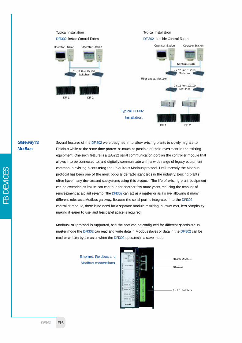
Typical Installations:
Ethernet Components
Cables:
BNC Cable (Requires BNC/TP Converter and Termination, MAX. 200m)
Shielded Twisted Pair (STP) (Requires HUBs or Switches, MAX. 100m)
Fibre Optics (Requires HUBs or Switches, MAX. 2Km)
HUB or Switch 10/100 Mbps (if STP or Fiber)
2 Ethernet NICs 10/100 Mbps per workstation
Fibre Optics to STP Converter (if Fiber is used)
ControlRoom
10 Base-TEthernet
Non-classifiedArea #1
Non-classifiedArea #2
HazardousArea
Fieldbus
10 Base-FLEthernet (fiber optic)Fibre optics is ideal for
networking between buildings
OtherRoom
DFI302 16F
FB D
EVIC
ES
Typical DFI302
Installation.
Several features of the DFI302 were designed in to allow existing plants to slowly migrate to
Fieldbus while at the same time protect as much as possible of their investment in the existing
equipment. One such feature is a EIA-232 serial communication port on the controller module that
allows it to be connected to, and digitally communicate with, a wide range of legacy equipment
common in existing plants using the ubiquitous Modbus protocol. Until recently the Modbus
protocol has been one of the most popular de facto standards in the industry. Existing plants
often have many devices and subsystems using this protocol. The life of existing plant equipment
can be extended as its use can continue for another few more years, reducing the amount of
reinvestment at a plant revamp. The DFI302 can act as a master or as a slave, allowing it many
different roles as a Modbus gateway. Because the serial port is integrated into the DFI302
controller module, there is no need for a separate module resulting in lower cost, less complexity
making it easier to use, and less panel space is required.
Modbus RTU protocol is supported, and the port can be configured for different speeds etc. In
master mode the DFI302 can read and write data in Modbus slaves or data in the DFI302 can be
read or written by a master when the DFI302 operates in a slave mode.
Gateway toModbus
Ethernet, Fieldbus and
Modbus connections.
Typical Installation
DFI302 inside Control Room
Typical Installation
DFI302 outside Control Room
Operator Station Operator Station
2 x 12 Port 10/100Switches
DFI 1 DFI 2
Operator Station Operator Station
2 x 12 Port 10/100Switches
STP, Max. 100m
2 x 12 Port 10/100Switches
Fiber optics, Max 2km
DFI 1 DFI 2
EIA 232 Modbus
Ethernet
4 x H1 Fieldbus

smar
17F
Integrating Legacy Subsystems
Many existing plant subsystems for HTG, weighing, loading terminals and flow computation, and
of course many PLCs use the Modbus protocol. Additionally, it may take some time before some
highly specialised equipment become available in a Fieldbus version, in the interim existing
Modbus equipment may be used and a DFI302 gateway will be required. The DFI302 controller
polls data through the serial port and makes it available on the Ethernet, while at the same time
performing the normal Fieldbus tasks on the four H1 ports.
DFI302 as a Modbus gateway in a
master role.
The DFI302 uses the standard Modbus commands for read and write making the slave data available
for use in the control strategy, or for display and trending in the operator workstation. Operator may
also actuate on the slave devices and perform other supervisory functions. Inputs are made available
as normal parameters, that may be used as part of the control strategy, or simply for monitoring, alarm
and trend.
Integrating Fieldbus to Legacy Systems
Because of the popularity of the Modbus protocol in the early days, most legacy systems such as
DCS or PLC have serial interface modules that support Modbus. This may be used to supervise
Fieldbus instruments through a DFI302 acting as a gateway. The DFI302 controller responds to
polls from the master on its serial port with data accessed from the relevant H1 Fieldbus port,
while at the same time performing the normal Fieldbus tasks on the Ethernet too.
DFI302 as a Modbus
gateway in a slave role.
Ethernet
DFI302
Modbus
Proprietary ControlNetwork
Legacy systemwith Modbus card
Modbus
DFI302 asModbus slave
Fieldbus

DFI302 18F
FB D
EVIC
ES
Through the DFI302 Fieldbus devices can be connected to an existing legacy control system
enabling the existing system to access some of the capabilities provided by Fieldbus devices.
Traditional process variables and controller gains can be mapped from Fieldbus to the database of
existing system, but of course the existing system doesn't have the control level networking
bandwidth and software capability do fully benefit from the Fieldbus technology. However, it may
be acceptable in a transition period to an open system.
User friendly
The Modbus port is very easy to use. It can be configured without having set any DIP switches. A
status LED on the front panel indicates active communication.
The DFI302 was specifically, and primarily, designed to operate with Fieldbus instruments. All
common field instrument types are available in Fieldbus versions, therefore the amount of
conventional I/O points required in a system is drastically reduced and will eventually be
eliminated. However, since many applications require connection of old or new devices that don't
have Fieldbus communication, the DFI302 may also be fitted with conventional discrete and
analogue I/O on an extended backplane.
The DFI302 may be installed close to the sensors and actuators, thereby eliminating long wire runs
and associated marshalling panels and cable trays for the conventional I/O, with subsequent
savings further reducing overall system cost.
Conventional I/O-subsystem
DFI302 with extended
backplane fitted with
conventional I/O modules.
Flexible and scaleable
Since the I/O-subsystem is modular, you need not worry about future expansion and spare
capacity now. Just buy what you require for your current application. The modularity gives you
the flexibility to mix and match the right quantity for each I/O type that you need. As your
demand increases or changes, additional backplane segments added and modules can be
plugged in to the system. Each controller module can be fitted with an I/O-subsystem for up to
256 points. Since several DFI302 can be networked together in a system, a very large amount of
conventional I/O can be handled.

smar
19F
The I/O-subsystem modules are multiple-channel high-density, typically packaged with as many
as 16 channels per module. The DFI302 therefore only requires half the panel space compared to
a device with only eight channels per module. And it is much lower cost too. Modules plug-in
using and industrial grade connector, and are held in place by a robust metal screw. All I/O
modules are isolated from the rest of the DFI302. All I/O circuits are designed so that accidental
normal-mode connection of 1000 VAC/DC to discrete I/O field terminals for an unlimited time
does not destroy any devices in I/O group other than the circuit to which the voltage was
applied.
The DFI302 Power Supply modules have a 24 VDC output used to power the I/O modules. It can
at the same time be used to power conventional field devices. There is no need for external bulk
power supplies. All is part of the modular DFI302. All modules are packaged in the same form
factor, allowing you to mix all types of I/O in any backplane position, irrespective of their voltage
levels. I/O modules are available of the following basic types:
Basic I/O Types
Discrete input - DC
Discrete input - AC
Discrete output - Transistor
Discrete output - Relay
Discrete output - Triac
Analog input
Analog output
Temperature input
Pulse input
The best way to measure temperature is to use field mounted Fieldbus temperature transmitters
(TT302). However, for applications sensitive to initial cost or in plant retrofit using existing wiring,
temperature modules in the DFI302 may instead be used. The temperature input module has a
universal direct sensor input accepting eight channels. The module has a built-in cold junction
compensation, temperature linearization and accepts the following sensors:
RTD: Cu10 (GE), Ni120 (Edison curve #7), Pt50, Pt100, Pt500 (IEC), Pt50 and Pt100 (JIS);
Thermocouple: B, E, J, K, N, R, S, T, L and U (DIN);
Voltage: -50 to 500 mV;
Resistance: 0-2000 ohm.
Because a single module accepts both thermocouples and RTDs, you have greater flexibility and
the amount of module types and spares required is reduced. Because it accepts low level signals
such as mV and ohm, you can use it with load cells and other sensors without the need for
intermediate signal conditioners.

DFI302 20F
FB D
EVIC
ES
Ideally Fieldbus instruments shall be used as far as possible, but when not available the second
best way is to use field mounted Fieldbus to current converters (FI302) and current to Fieldbus
converters (IF302). These reduce the field wiring and make future migration of devices to Fieldbus
easier. However, for applications sensitive to initial cost or in plant retrofit using existing wiring,
analogue modules in the DFI302 may instead be used. The analogue I/O modules accept the
following inputs and outputs:
Analog input: 4-20 mA/0-20 mA/1-5 V/0-10 V/-10-10 V;
Analog output: 4-20 mA/0-20 mA.
A single analogue output module gives you the option of both current and voltage output to
meet varying requirements. Output modules are current limited and protected against inductive
loads. In case of failure, a discrete output is driven to an individually configured fail-safe position
being true, false or hold last position.
The pulse input module is capable of measuring frequencies up to 10 kHz.
See the ordering section for a complete listing of modules.
Connect non-Fieldbus Devices in new Systems
Modern plants require some sensors and simple devices that are still not available with Fieldbus
communication. These include discrete switches, contacts and solenoid valves, pulse signals from
flow meters, and direct input from temperature sensors. Moreover, although all of the most
common transmitters used in the industry are available from Smar or other manufacturers in
Fieldbus version, some rare types only exist in analogue versions. Using the conventional I/O-
subsystem, all analogue and discrete devices may be tightly integrated to SYSTEM302.
Upgrading Existing Installations
When the DFI302 is used in the revamp of existing plants the I/O-subsystem may be used to
interface the large amounts of conventional I/O from the existing instruments that will not yet
be upgraded to Fieldbus. Typically existing devices are eventually exchanged by Fieldbus
instruments, being replaced in stages. During the transition period until those instruments have
been replaced with Fieldbus devices the I/O-subsystem provides a smooth transition.
Easy to install
External field wiring have multiple point plug-in type connectors so that I/O modules are capable
of being inserted into or removed from their backplane without unscrewing external wires. It
also allows all the wiring to be made before I/O-module installation. Field I/O wiring is screwed
on to the connectors. The connectors have an optional keying which may be set in advance
preventing the wrong wire from going into the wrong module. You will always connect correctly,
eliminating the risk of applying high voltage to a low voltage terminal. Module damage
protection is not enough. If sensors or actuator wiring is mixed up, the plant can go haywire.
Keying can on DFI302 therefore be made unique for each and every connector (not just module
type) ensuring a correct match and safe operation. Thereby you ensure that only the intended
sensor goes to its assigned module channel. Each type of module is uniquely identified by a type

smar
21F
Unique keying for each connector
prevents mistakes.
All I/O modules have a LED to indicate that it is powered. Discrete modules also have clearly
visible local LED status indicators to monitor the status of each input and output.
The DFI302 can also perform control similar to a conventional controller module. With
SYSTEM302 you can therefore chose to do control anywhere, in a transmitter, valve positioner, in
the controller or in all of them at the same time. The graphical system configuration and
maintenance software (SYSCON, see separate data sheet) makes configuration entry,
management, documentation and troubleshooting very easy. DFI302 is suitable for continuous
regulatory and discrete control, as well as for batch applications. Tags are shared throughout the
system, hence there is no need to map or patch variables via additional blocks or elements. Data
from Fieldbus as well as conventional devices can be used in the control strategy. A built-in Y2K
compatible real time clock lets you build control strategies that take date and time of day into
account.
number and serial number. In addition, each Module clearly indicates the designated field signal
range and type. Quick-reference charts are permanently attached to the inside of the modules'
front door. The charts clarify proper module wiring. On-line replacement of any module is
possible without having to re-configure system software, alter system wiring or cabling, or re-
initialise.
Process Controllerfor more controlcapability

DFI302 22F
FB D
EVIC
ES
The DFI302 itself requires no software license. Therefore you don't need to go through the trouble
of upgrading and registration when you expand your system.
Homogeneous Fieldbus Environment
The DFI302 use the same function blocks as Fieldbus instruments, same PID block, same AI block
etc. This means that one single software can be used to configure every part of the system,
transmitters, positioners and controller all in the same language. The problem of linking Fieldbus
blocks to proprietary languages is eliminated. SYSTEM302 lets you fully enjoy the benefits of
Fieldbus. The SYSCON configuration software can put the PID either in a transmitter, positioner or
controller by simply dragging and dropping. An analogue input looks the same if it is in a
pressure transmitter or a 4-20 mA input module in the I/O-subsystem. This makes the system
integrated and easier to use because you only need to install one set of hardware and learn one
single software.
SYSTEM302 gives you
the flexibility to do
control anywhere.
Fieldbus applied to a legacy system becomes heterogeneous as opposed
to SYSTEM302 with DFI302 which is homogeneous.
Controller Configuration Device Configuration
DFI302
Proprietary Network
Controllerand I/O
All Configuration
Conventional I/O

smar
23F
SYSTEM302 therefore compares favourably against hybrids of legacy architecture and Fieldbus
where the controller is configured in one language at one station, and the field instruments in
another language at another station (heterogeneous environment).
FOUNDATION Fieldbus Function blocks
The FOUNDATION Fieldbus (FF) functions blocks are especially suitable for continuos regulatory
control. Anybody familiar with the Smar CD600 controller or a DCS should feel right at home. The
DFI302 appears in the configuration tool as a device just like a transmitter or positioner on each
of its four H1 ports. Configuration download can be made to one part of the DFI302 without
affecting the control on the others making online changes and expansions easy without
disturbing the process. Blocks appear the same independent of their physical location. The
DFI302 block set include several advanced function blocks that complement the function blocks
in the field devices should they be required, resulting in a very powerful combination. The
Fieldbus blocks implement sophisticated schemes for status propagation between blocks,
making safety actions, reset-windup protection, and cascade initialisation etc. completely
automatic. Since the functionality is built into the blocks, no additional strategy building is
required to achieve these functions.
Function blocks receive inputs from other blocks, process them according to an internal user
selected algorithm and constants, providing an output which in turn is passed to the next block.
Input class blocks (in transmitters) receive their inputs from a sensor, and output blocks pass their
output to an actuator. Fieldbus blocks are exceptionally powerful, and a single block performs
several functions, reducing the number of blocks and configuration effort required.
Fieldbus blocks are primarily executed in devices in the field which results in better loop
integrity, while at the same time off-loading the controllers, reducing the number of controller
modules required, and therefore overall system cost.

DFI302 24F
FB D
EVIC
ES
Category Block Description
AI Analog Input
DI Discrete Input
Input PUL Pulse Input
MAI Multiple Analog Input
MDI Multiple Discrete Input
PID PID Control
SPLT Splitter
SPG Setpoint Generator
Control OSDL Output Signal Selector and Dynamic limiter
APID Advanced PID Control
EPID Enhanced PID Control
STEP Step Output PID
ARTH Arithmetic
CHAR Characterization
INTG Integrator
AALM Analog Alarm
CalculateISEL Input Signal Selector
TIME Timer
LLAG Lead Lag
DENS Density Calculation
CT Constant Generator
FFET Flip-Flop And Edge Trigger
RS Resource Block
Transducer and DIAG Diagnostic Block
Resource HC Hardware Configuration
TEMP Temperature Module Transducer
AO Multiple Analog Output
OutputDO Discrete Output
MAO Multiple Analog Output
MDO Multiple Discrete Output
Function Blocks .

smar
25F
User Friendly
The selected controller operating mode (run or hold) is clearly indicated on the front of the
controller by individual LEDs. The controller module continuously monitors its own status and
indicates power and failure via colour coded LED status indicators on each controller faceplate. A
relay contact on the module also change status at failure. This may be used as an additional alert
to the user, and as part of safety interlocks. Status indication include FAIL (the controller has
failed), HOLD (application program execution has been paused), RUN (normal operation), FORCE
(any I/O which is forced on or off ) etc.
View the plant graphically and browse
network devices and control strategies
in the SYSCON software.
A modern control system needs more than just configuration and monitoring software. More
than inflexible "closed" applications and inaccessible data associated with DCS. SYSTEM302
process visualisation, engineering and maintenance software run on a commercial or industrial
grade PC platform with the Windows NT operating system, which is the powerful basis for the
information architecture for today's enterprise. Windows is the de facto standard for computer
workstations. As Information Technology (IT) is playing and increasingly important role in the
process industry, SYSTEM302 is the platform to build upon.
In SYSTEM302, one or more of the computers operate in a server role. Work is carried out from the
same station or one or more workstation clients typically located in the control room. Client-
server communication is done using a combination of OLE, OPC, COM and DCOM technology, all
from the same server. The server accesses the DFI302 on the Ethernet network and makes the
information available to other workstations. All the information in the DFI302 itself and the
Fieldbus devices connected to it is made available to OPC and OLE clients.
OLE/OPC Client/Server Architecture

DFI302 26F
FB D
EVIC
ES
The DFI302 OLE server is a 32-bit application which essentially consists of two parts, the OPC (OLE
for Process Control) server and the OFC server (OLE for Fieldbus Configuration). OPC is a widely
accepted industry standard client-server technology for interchanging parameter values between
applications. OFC is a Smar initiative to fill in the gaps left by OPC. For example, OFC is used for
instantiation and linking of blocks and other functions required by Fieldbus but not provided by
OPC. The DFI302 OLE server inter-connects one or more client applications, such as the
configuration and maintenance tool SYSCON and the process visualisation. Multiple clients can
simultaneously access the server located in the same workstation or remotely over the Ethernet.
This enables a single distributed Fieldbus database to be shared among workstations, eliminating
inconsistencies.
OPC is the industrial version of OLE, it is tailored for the needs of industrial software. One of the major
benefits of OPC is that it makes information from the field available to a vast array of software for
supervisory control, historical trending, advanced control and auto-tuning, and also inferential sensing,
modelling, advanced control, optimisation and historians without the need for any drivers. There are
even OPC bridges that pass data from one OPC server to another such as from one system to another.
All kinds of software from different suppliers can therefore be added to SYSTEM302. New types of
software from many suppliers become available every day. Because OPC servers have been
developed for new as well as old field equipment such as programmable controllers etc., OPC is a
convenient way to connect existing equipment in a plant retrofit scenario, or to integrate other
subsystems. OPC makes things work together.
Single integrated system database
An OPC server feature called address space browsing gives SYSTEM302 a single integrated database
even if software from several third party suppliers are used. Once a tag has been created in a device, it
becomes available for access by client applications. From the client application you can browse or
navigate by pointing and clicking through a Windows explorer like hierarchy until you reach the
parameter. You don't have to retype any tags, eliminating problems due to typographical errors. Since
OPC is completely tag based, you don't have to deal with mapping of device addresses, memory
registers and bits and bytes etc. as was common with PLC and HMI combinations. OPC instead gives an
unprecedented level of integration and ease of use, yet complete openness and security.
Iconics Genesis
GraphworX32 OPC browser.
OPC technology seamlessly integrate software applications into a homogenous environment
where data is shared throughout the system and throughout the enterprise with the same name
as a single database, eliminating inconsistencies and many errors.

smar
27F
Integrating with other industrial applications
Because DFI302 and its OLE server is built around a whole suite of open technologies, it is very
easy to integrate to other applications that perform various tasks such as Human-Machine
Interface (HMI), advanced control or Enterprise Resource Planning (ERP). Any application which is an
OPC client can access the Fieldbus data from the OPC server. SYSTEM302 is the only system which is
open in both ends, up and down. Any Fieldbus device, any OPC client for operation.
Wonderware
FactorySuite2000 OPC browser
accessing all Fieldbus device
data.
Integration with Excel and other MS-Office applications
An optional OPC client allows you to access process and production information disseminated
throughout the enterprise, not only for use by operators and engineers, but also managers and
others in the business domain of the plant. MS-Office applications such as Excel, Word and other
"front office" applications receive live real-time data piped straight from the plant floor onto
your desktop. Use continuos and discrete process variables, integrated totals and diagnostics to
generate professionally looking and easy to use reports in table or chart format using Excel. The
familiarity of MS-Office makes it possible for anybody to get the information they need to make
better decisions. Just put the data into your spreadsheet by browsing the OPC servers in the
system. There is no need to type any cryptic commands or deal with obscure terminology. You no
longer have to gather data "snapshots" manually which is tedious, error prone and untimely.
Instead data is continuously and instantly updated without errors.
Rensen OPC link
for MS-Office

DFI302 28F
FB D
EVIC
ES
The built in statistical and computational functions of Excel, as well as sorting and filtering
features make analysis very simple. It has never been easier to handle large amount of process
data. It is even possible to perform calculations using the powerful computational and lookup
functions in Excel and write it back to controllers and field devices.
Use Excel to report with Bar,
line, pie, area or other charts
on 2D or 3D charts.
The OPC link for MS-Office provides a convenient way to import live data gathered by any OPC
server. A live link can simply be made into the spreadsheet. Combined with the OPC server's
accessibility through scripting languages such as Excel Visual Basic, it becomes a powerful tool
that allows to completely oversee the plant floor from within the office.
Network Security
OLE and OPC are open technologies used to disseminate information across the enterprise. There
is therefore a need to protect the data. The OLE server therefore equipped with COM and DCOM
security features. The Windows NT server domain-based scheme has a single security database
and is therefore easy to manage. Setup is done from the normal Windows NT User Manager.
smar
29F
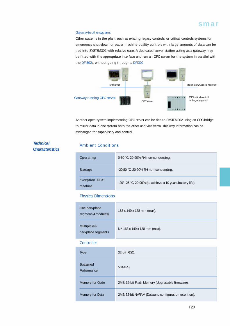
Gateway running OPC server.
Gateway to other systems
Other systems in the plant such as existing legacy controls, or critical controls systems for
emergency shut-down or paper machine quality controls with large amounts of data can be
tied into SYSTEM302 with relative ease. A dedicated server station acting as a gateway may
be fitted with the appropriate interface and run an OPC server for the system in parallel with
the DFI302s, without going through a DFI302.
Another open system implementing OPC server can be tied to SYSTEM302 using an OPC bridge
to mirror data in one system onto the other and vice versa. This way information can be
exchanged for supervisory and control.
TechnicalCharacteristics
Ambient Conditions
Operating 0-60 °C, 20-90% RH non-condensing.
Storage -20.80 °C, 20-90% RH non-condensing.
Physical Dimensions
One backplane163 x 149 x 138 mm (max).
segment (4 modules)
Multiple (N)N * 163 x 149 x 138 mm (max).
backplane segments
Controller
Type 32-bit RISC.
Sustained50 MIPS.
Performance
Memory for Code 2MB, 32-bit Flash Memory (Upgradable firmware).
Memory for Data 2MB, 32-bit NVRAM (Data and configuration retention).
Enthernet
OPC server
Proprietary Control Network
ESD/critical controlor Legacy system
exception DF31
module-20° -25 °C, 20-90% (to achieve a 10 years battery life).

DFI302 30F
FB D
EVIC
ES
Number of Ports 4, independent with DMA
Physical Layer Standard ISA-S50.02-1992
Fieldbus InterfaceBaud Rate 31.25Kbps (H1)
MAU Type Passive (not bus powered)
Intrinsic Safety NOT compliant
Isolation 500 Vac (each channel)
Operation+5V ±5% / 0.95A (typical).
Voltage / Current
Connector Ethernet RJ-45.
Connector EIA-232 RJ-12.
Input AC 90 to 260 Vac at 47 to 440 Hz.
Input DC 127 to 367 Vdc.
Maximum45 Watts
consumption
Output Voltage 24 Vdc ±1% for load 0 to full load voltage between 90~260 Vac.
Output Current 0 a 1.5 A.
Ripple 20 mv peak to peak.
Alarme output 1 A, 30 Vdc SPST, Fail closed.
Input 90~260 Vac.
Output 5V @ 3A, 24V @ 0.3A.
Maximum35 VA.
consumption
Power Supply for Backplane
Power Supply for Fieldbus

smar
31F
Isolationbetween output and enclosure ground: 500 VRMS
between input and output: 3000 VRMS
Power Supply Impedance for Fieldbus
Input 24 to 32 Vdc ±10%
Output Current 340 mA (máx).
Output Overcurrent Limited in 500 mA
Input Fuse 2,5 A.
SYSTEM302 Server hardware.
Windows NT 4.0 Workstation Service Pack 3.
CD-ROM drive.
Ethernet card 10/100Base-T.
32 MB RAM.
10 MB hard disk.
800 x 600, 256 colour display.
Pentium 60 MHz.
Digital Input
PartNumber
DF11
DF12
DF13
DF14
DF15
DF16
DF17
DF18
DF19
DF20
InputType
DC
AC
Switch
InputPoints
16
8
16
8
Max. InputVoltage
30 Vdc
60 Vdc
75 Vdc
140 Vdc
30 Vdc
140 Vac
264 Vac
140 Vac
264 Vac
-
InputCurrent
7.5 mA
10 mA
-
OnVoltage
> 15 Vdc
> 30 Vdc
> 38 Vdc
> 95 Vdc
< 5 Vdc
> 100 Vac
> 200 Vac
> 100 Vac
> 200 Vac
-
OffVoltage
< 5 Vdc
< 9 Vdc
< 12 Vdc
< 25 Vdc
> 20 Vdc
< 30 Vac
< 50 Vac
< 30 Vac
< 50 Vac
-
On/OffDelay
30 µs (On)
50 µs (Off )
5 ms (On)
42 ms (Off)
-
Points perGroup
8 pts
4 pts
8 pts
DrawnCurrent fromInternal 5 Vdc
80 mA
50 mA
80 mA
45 mA
Minimum Server Requirements

DFI302 32F
FB D
EVIC
ES
Digital Output
PartNumber
DF21
DF22
DF23
DF24
DF25
DF26
DF27
DF28
DF29
DF30
DF31
OutputType
Transistor
Transistor
Triac
Relay
OutputPoints
16
16
8
16
4 NO4 NO4 NC4 NC4 NO4 NC8 NO8 NO4 NO4 NO4 NC4 NC4 NO4 NC
OutputVoltage
30 Vdc
65 Vdc
20 to
240 Vdc
250 Vac
110 Vdc
ContinuousCurrentper Point
0.5 A (sink)
1 A (Source)
1 A
5 A at 250 Vac
5 A at 24 Vdc
ContinuousCurrentper Group
8 A
8 A
4 A (40 ºC)
2 A (60 ºC)
10 A
On/OffDelay
250 µs (On)3 µs (Off)250 µs (On)50 µs (Off)
1/2 cycle
10 ms
DrawnCurrent fromInternal 5 Vdc
70 mA
115 mA
20 mA
70 mA
20 mA
Points perGroup
16
8
4
8
4
8
4
Max.LeakageCurrent
100 µA
200 µA
0.5 mA at
100 Vac
-
-
Digital Input/OutputPartNumber
DF32
DF33
DF34
DF35
DF36
DF37
DF38
DF39
DF40
InputSpecificationssee DF11
see DF12
see DF13
see DF11
see DF12
see DF13
see DF11
see DF12
see DF13
OutputSpecifications
see DF25
see DF26
see DF27
Drawn Currentfrom Internal 5 Vdc
60 mA
InputType
DC
OutputType
Relay
InputPoints
8
OutputPoints
4

smar
33F
DimensionsCo
nnec
tion
of L
ocal
Exp
ansio
nDi
men
sions
in m
m (i
nch)

DFI302 34F
FB D
EVIC
ES
The DFI302 is completely modular. The modules and other parts are ordered individually to the
desired combination. Notes:
1. One backplane required for every four modules.
2. One flat cable required between backplane sections.
3. One terminator required per DFI302
4. One power supply for backplane and one processor module required as minimum for each DFI302.
The must be unique and it must occupy the first or second slot when accessing I/O modules.
5. Additional power supply for backplane modules may be inserted as required.
6. The OLE server license is available in several levels with different function blocks capacities.
7. Check availability of Redundancy, 100 Mbit/s and High Speed Ethernet standard.
Ordering Codes
CONTROLLER
MODEL DESCRIPTION
DF51 DFI302 Processor 1x10Mbps, 4xH1
POWER
MODEL DESCRIPTION
DF47 Intrinsic Safety Barrier for Fieldbus
DF48 Repeater for Fieldbus
DF49 Power Supply Impedance for Fieldbus (2 ports)
DF50 Power Supply for Backplane 90-264VAC
DF52 Power Supply for Fieldbus
DF53 Power Supply Impedance for Fieldbus (4 ports)
DISCRETE INPUT
MODEL DESCRIPTION
DF11 2 Groups of 8 24VDC Inputs (Isolated)
DF12 2 Groups of 8 48VDC Inputs (Isolated)
DF13 2 Groups of 8 60VDC Inputs (Isolated)
DF14 2 Groups of 8 125VDC Inputs (Isolated)
DF15 2 Groups of 8 24VDC Inputs (Sink)(Isolated)
DF16 2 Groups of 4 120VAC Inputs (Isolated)
DF17 2 Groups of 4 240VAC Inputs (Isolated)
DF18 2 Groups of 8 120VAC Inputs (Isolated)
DF19 2 Groups of 8 240VAC Inputs (Isolated)
DF20 1 Group of 8 On/Off Switches
DISCRETE OUTPUT
MODEL DESCRIPTION
DF21 1 Group of 16 Open Collector Outputs
DF22 2 Group of 8 Transistor Outputs (source) (Isolated)
DF23 2 Groups of 4 120/240VAC Outputs
DF24 2 Groups of 8 120/240VAC Outputs
DF25 2 Groups of 4 NO Relays Outputs
DF26 2 Groups of 4 NC Relays Outputs
DF27 1 Group of 4 NO and 4 NC Relay Outputs
DF28 2 Groups of 8 NO Relays Outputs
DF29 2 Groups of 4 NO Relays Outputs (W/o RC)
DF30 2 Groups of 4 NC Relays Outputs (W/o RC)
DF31 1 Group of 4 NO and 4 NC Relay Outputs (W/o RC)

smar
35F
COMBINED DISCRETE INPUT AND OUTPUT
MODEL DESCRIPTION
DF32 1 Group of 8 24VDC Inputs and 1 Group of 4 NO Relays
DF33 1 Group of 8 48VDC Inputs and 1 Group of 4 NO Relays
DF34 1 Group of 8 60VDC Inputs and 1 Group of 4 NO Relays
DF35 1 Group of 8 24VDC Inputs and 1 Group of 4 NC Relays
DF36 1 Group of 8 48VDC Inputs and 1 Group of 4 NC Relays
DF37 1 Group of 8 60VDC Inputs and 1 Group of 4 NC Relays
DF38 1 Group of 8 24VDC Inputs, 1 Group of 2 NO and 2 NC Relays
DF39 1 Group of 8 48VDC Inputs, 1 Group of 2 NO and 2 NC Relays
DF40 1 Group of 8 60VDC Inputs, 1 Group of 2 NO and 2 NC Relays
PULSE INPUT
MODEL DESCRIPTION
DF41 2 Groups of 8 pulse inputs - low frequency
DF42 2 Groups of 8 pulse inputs - high frequency
ANALOGUE INPUT
MODEL DESCRIPTION
DF43 1 Group of 8 analog Inputs
DF44 1 Group of 8 analog Inputs with shunt resistors
DF45 1 Group of 8 Temperature Inputs
ANALOGUE OUTPUT
MODEL DESCRIPTION
DF46 1 Group of 4 Analog output
BACKPLANE, CABLE AND ACESSORIES
MODEL DESCRIPTION
DF0 Box used in empty slots, in the rack
DF1 Rack with 4 Slots
DF2 Terminator for the last rack
DF3 Flat Cable to connect two racks - Length 65 mm
DF4 Flat Cable to connect two racks - Length 651 mm
DF5 Flat Cable to connect two racks - Length 814 mm
DF6 Flat Cable to connect two racks - Length 977 mm
DF7 Flat Cable to connect two racks - Length 1140 mm
DF8 Flat cable connection kit
DF9 Standalone support for 1 module
DF10 Standalone support for 2 modules
DF54 Twisted-Pair (10 Base T) Cable - Length 2 m
DF55 Twisted-Pair (10 Base T) Cable - Length 2 m - Crossover
DFI302 OLE SERVER
MODEL DESCRIPTION
DFI302-SVR-1 16 Function Blocks
DFI302-SVR-2 32 Function Blocks
DFI302-SVR-3 64 Function Blocks
DFI302-SVR-4 128 Function Blocks
DFI302-SVR-5 256 Function Blocks
DFI302-SVR-6 512 Function Blocks
DFI302-SVR-7 1024 Function Blocks
DFI302-SVR-8 2048 Function Blocks
DFI302-SVR-9 4096 Function Blocks