dg0598 smartfusion2 dual axis motor control starter kit
TRANSCRIPT

DG0598Demo Guide
SmartFusion2 Dual-Axis Motor Control Starter Kit

50200598. 7.0 12/17
Microsemi Corporate HeadquartersOne Enterprise, Aliso Viejo,CA 92656 USAWithin the USA: +1 (800) 713-4113 Outside the USA: +1 (949) 380-6100Fax: +1 (949) 215-4996Email: [email protected]
© 2016 Microsemi Corporation. All rights reserved. Microsemi and the Microsemi logo are trademarks of Microsemi Corporation. All other trademarks and service marks are the property of their respective owners.
Microsemi makes no warranty, representation, or guarantee regarding the information contained herein or the suitability of its products and services for any particular purpose, nor does Microsemi assume any liability whatsoever arising out of the application or use of any product or circuit. The products sold hereunder and any other products sold by Microsemi have been subject to limited testing and should not be used in conjunction with mission-critical equipment or applications. Any performance specifications are believed to be reliable but are not verified, and Buyer must conduct and complete all performance and other testing of the products, alone and together with, or installed in, any end-products. Buyer shall not rely on any data and performance specifications or parameters provided by Microsemi. It is the Buyer's responsibility to independently determine suitability of any products and to test and verify the same. The information provided by Microsemi hereunder is provided “as is, where is” and with all faults, and the entire risk associated with such information is entirely with the Buyer. Microsemi does not grant, explicitly or implicitly, to any party any patent rights, licenses, or any other IP rights, whether with regard to such information itself or anything described by such information. Information provided in this document is proprietary to Microsemi, and Microsemi reserves the right to make any changes to the information in this document or to any products and services at any time without notice.
About Microsemi
Microsemi Corporation (Nasdaq: MSCC) offers a comprehensive portfolio of semiconductor and system solutions for aerospace & defense, communications, data center and industrial markets. Products include high-performance and radiation-hardened analog mixed-signal integrated circuits, FPGAs, SoCs and ASICs; power management products; timing and synchronization devices and precise time solutions, setting the world's standard for time; voice processing devices; RF solutions; discrete components; enterprise storage and communication solutions, security technologies and scalable anti-tamper products; Ethernet solutions; Power-over-Ethernet ICs and midspans; as well as custom design capabilities and services. Microsemi is headquartered in Aliso Viejo, California, and has approximately 4,800 employees globally. Learn more at www.microsemi.com.

DG0598 Demo Guide Revision 7.0 iii
Contents
1 Revision History . . . . . . . . . . . . . . . . . . . . . . . . . . . . . . . . . . . . . . . . . . . . . . . . . . . . . 11.1 Revision 7.0 . . . . . . . . . . . . . . . . . . . . . . . . . . . . . . . . . . . . . . . . . . . . . . . . . . . . . . . . . . . . . . . . . . . . . . . 1
1.2 Revision 6.0 . . . . . . . . . . . . . . . . . . . . . . . . . . . . . . . . . . . . . . . . . . . . . . . . . . . . . . . . . . . . . . . . . . . . . . . 1
1.3 Revision 5.0 . . . . . . . . . . . . . . . . . . . . . . . . . . . . . . . . . . . . . . . . . . . . . . . . . . . . . . . . . . . . . . . . . . . . . . . 1
1.4 Revision 4.0 . . . . . . . . . . . . . . . . . . . . . . . . . . . . . . . . . . . . . . . . . . . . . . . . . . . . . . . . . . . . . . . . . . . . . . . 1
1.5 Revision 3.0 . . . . . . . . . . . . . . . . . . . . . . . . . . . . . . . . . . . . . . . . . . . . . . . . . . . . . . . . . . . . . . . . . . . . . . . 1
1.6 Revision 2.0 . . . . . . . . . . . . . . . . . . . . . . . . . . . . . . . . . . . . . . . . . . . . . . . . . . . . . . . . . . . . . . . . . . . . . . . 1
1.7 Revision 1.0 . . . . . . . . . . . . . . . . . . . . . . . . . . . . . . . . . . . . . . . . . . . . . . . . . . . . . . . . . . . . . . . . . . . . . . . 1
2 SmartFusion2 Dual-Axis Motor Control Starter Kit . . . . . . . . . . . . . . . . . . . . . . . . . . 22.1 Introduction . . . . . . . . . . . . . . . . . . . . . . . . . . . . . . . . . . . . . . . . . . . . . . . . . . . . . . . . . . . . . . . . . . . . . . . 2
2.2 Design Requirements . . . . . . . . . . . . . . . . . . . . . . . . . . . . . . . . . . . . . . . . . . . . . . . . . . . . . . . . . . . . . . . 2
2.3 Demo Design . . . . . . . . . . . . . . . . . . . . . . . . . . . . . . . . . . . . . . . . . . . . . . . . . . . . . . . . . . . . . . . . . . . . . . 2
2.4 Demo Design Features . . . . . . . . . . . . . . . . . . . . . . . . . . . . . . . . . . . . . . . . . . . . . . . . . . . . . . . . . . . . . . 3
2.5 Setting Up the Demo Design . . . . . . . . . . . . . . . . . . . . . . . . . . . . . . . . . . . . . . . . . . . . . . . . . . . . . . . . . . 32.5.1 Setting Up the Hardware . . . . . . . . . . . . . . . . . . . . . . . . . . . . . . . . . . . . . . . . . . . . . . . . . . . . . . 32.5.2 Installing the Motor Control GUI . . . . . . . . . . . . . . . . . . . . . . . . . . . . . . . . . . . . . . . . . . . . . . . . 4
2.6 Running the Demo Design . . . . . . . . . . . . . . . . . . . . . . . . . . . . . . . . . . . . . . . . . . . . . . . . . . . . . . . . . . . 12
2.7 Running the BLDC Motors . . . . . . . . . . . . . . . . . . . . . . . . . . . . . . . . . . . . . . . . . . . . . . . . . . . . . . . . . . . 14
2.8 Running Stepper Motors . . . . . . . . . . . . . . . . . . . . . . . . . . . . . . . . . . . . . . . . . . . . . . . . . . . . . . . . . . . . 202.8.1 Continuous Mode . . . . . . . . . . . . . . . . . . . . . . . . . . . . . . . . . . . . . . . . . . . . . . . . . . . . . . . . . . 212.8.2 Position Mode . . . . . . . . . . . . . . . . . . . . . . . . . . . . . . . . . . . . . . . . . . . . . . . . . . . . . . . . . . . . . 21
2.9 Register Dump Feature . . . . . . . . . . . . . . . . . . . . . . . . . . . . . . . . . . . . . . . . . . . . . . . . . . . . . . . . . . . . . 24
3 Appendix: Jumper Settings . . . . . . . . . . . . . . . . . . . . . . . . . . . . . . . . . . . . . . . . . . . 28
4 Appendix: Connecting the Motor Terminals . . . . . . . . . . . . . . . . . . . . . . . . . . . . . . 294.1 BLDC Motor Connections . . . . . . . . . . . . . . . . . . . . . . . . . . . . . . . . . . . . . . . . . . . . . . . . . . . . . . . . . . . 29
4.1.1 Stepper Motor Connections . . . . . . . . . . . . . . . . . . . . . . . . . . . . . . . . . . . . . . . . . . . . . . . . . . . 30

DG0598 Demo Guide Revision 7.0 iv
Figures
Figure 1 SmartFusion2 Dual Axis Motor Control Demo Hardware Setup . . . . . . . . . . . . . . . . . . . . . . . . . . . . 3Figure 2 Identifying the SmartFusion2 Motor Control Kit USB Driver . . . . . . . . . . . . . . . . . . . . . . . . . . . . . . . 5Figure 3 Device Manager . . . . . . . . . . . . . . . . . . . . . . . . . . . . . . . . . . . . . . . . . . . . . . . . . . . . . . . . . . . . . . . . 6Figure 4 Installing the USB Driver - Opening the Properties Window . . . . . . . . . . . . . . . . . . . . . . . . . . . . . . . 7Figure 5 Selecting the Right VID Number in the Properties Window . . . . . . . . . . . . . . . . . . . . . . . . . . . . . . . 8Figure 6 Updating Driver Software . . . . . . . . . . . . . . . . . . . . . . . . . . . . . . . . . . . . . . . . . . . . . . . . . . . . . . . . . 8Figure 7 Updating Driver Software - Locate and Install the Driver Software Manually . . . . . . . . . . . . . . . . . . 9Figure 8 Updating Driver Software - Selecting the Driver Location . . . . . . . . . . . . . . . . . . . . . . . . . . . . . . . . . 9Figure 9 Model Selection . . . . . . . . . . . . . . . . . . . . . . . . . . . . . . . . . . . . . . . . . . . . . . . . . . . . . . . . . . . . . . . 10Figure 10 Windows Security Dialog . . . . . . . . . . . . . . . . . . . . . . . . . . . . . . . . . . . . . . . . . . . . . . . . . . . . . . . . 10Figure 11 Successful Installation Message . . . . . . . . . . . . . . . . . . . . . . . . . . . . . . . . . . . . . . . . . . . . . . . . . . . 11Figure 12 Verifying the Installed Driver Software . . . . . . . . . . . . . . . . . . . . . . . . . . . . . . . . . . . . . . . . . . . . . . 11Figure 13 Launching the SmartFusion2 Dual-Axis Motor Control GUI . . . . . . . . . . . . . . . . . . . . . . . . . . . . . . 12Figure 14 SmartFusion2 Motor Control GUI - Launch Window . . . . . . . . . . . . . . . . . . . . . . . . . . . . . . . . . . . . 13Figure 15 SmartFusion2 Motor Control GUI - BLDC Motor Screen . . . . . . . . . . . . . . . . . . . . . . . . . . . . . . . . 14Figure 16 Configuring Motor Parameters Window . . . . . . . . . . . . . . . . . . . . . . . . . . . . . . . . . . . . . . . . . . . . . 15Figure 17 Motor Specifications Configuration Window . . . . . . . . . . . . . . . . . . . . . . . . . . . . . . . . . . . . . . . . . . 15Figure 18 SmartFusion2 Motor Control GUI - Run or Stop All Motors . . . . . . . . . . . . . . . . . . . . . . . . . . . . . . 16Figure 19 SmartFusion2 Motor Control GUI - Start Plotting . . . . . . . . . . . . . . . . . . . . . . . . . . . . . . . . . . . . . . 17Figure 20 Plot Waveforms Window . . . . . . . . . . . . . . . . . . . . . . . . . . . . . . . . . . . . . . . . . . . . . . . . . . . . . . . . . 17Figure 21 Plot Waveforms Window with Options . . . . . . . . . . . . . . . . . . . . . . . . . . . . . . . . . . . . . . . . . . . . . . 18Figure 22 SmartFusion2 Motor Control GUI - Displaying Speed and Current . . . . . . . . . . . . . . . . . . . . . . . . 19Figure 23 SmartFusion2 Motor Control GUI - Saving and Loading Waveforms . . . . . . . . . . . . . . . . . . . . . . . 20Figure 24 SmartFusion2 Motor Control GUI - Stepper Motor Window . . . . . . . . . . . . . . . . . . . . . . . . . . . . . . 21Figure 25 SmartFusion2 Motor Control GUI - Stepper Motor in Position Mode . . . . . . . . . . . . . . . . . . . . . . . 22Figure 26 Configure Stepper Motor Parameters Window . . . . . . . . . . . . . . . . . . . . . . . . . . . . . . . . . . . . . . . . 23Figure 27 Register Dump window . . . . . . . . . . . . . . . . . . . . . . . . . . . . . . . . . . . . . . . . . . . . . . . . . . . . . . . . . . 24Figure 28 Register Dump window—BLDC Tab . . . . . . . . . . . . . . . . . . . . . . . . . . . . . . . . . . . . . . . . . . . . . . . 25Figure 29 Register Dump window—Stepper Tab . . . . . . . . . . . . . . . . . . . . . . . . . . . . . . . . . . . . . . . . . . . . . . 26Figure 30 Sample Csv File . . . . . . . . . . . . . . . . . . . . . . . . . . . . . . . . . . . . . . . . . . . . . . . . . . . . . . . . . . . . . . . 27Figure 31 Jumpers on SmartFusion2 Starter Kit . . . . . . . . . . . . . . . . . . . . . . . . . . . . . . . . . . . . . . . . . . . . . . . 28Figure 32 Wiring Diagram for BLDC Motor Connectors . . . . . . . . . . . . . . . . . . . . . . . . . . . . . . . . . . . . . . . . . 29Figure 33 Wiring Diagram for Stepper Motor Connectors . . . . . . . . . . . . . . . . . . . . . . . . . . . . . . . . . . . . . . . . 30

DG0598 Demo Guide Revision 7.0 v
Tables
Table 1 Design Requirements . . . . . . . . . . . . . . . . . . . . . . . . . . . . . . . . . . . . . . . . . . . . . . . . . . . . . . . . . . . . 2Table 2 Jumper Settings on the SmartFusion2 Starter Kit Board . . . . . . . . . . . . . . . . . . . . . . . . . . . . . . . . 28

Revision History
DG0598 Demo Guide Revision 7.0 1
1 Revision History
The revision history describes the changes that were implemented in the document. The changes are listed by revision, starting with the current publication.
1.1 Revision 7.0The following is a summary of changes made in revision 7.0 of this document.
• Design Requirements, page 2 was edited to change the version of Libero SoC to v11.8 SP2 and the version of Microsemi Motor Control GUI to v5.8.
• Programming files and GUI files links were edited in Demo Design, page 2 with respect to Libero v11.8 SP2 release.
1.2 Revision 6.0The following is a summary of the changes made in revision 6.0 of this document.
• Added new section Register Dump Feature, page 24.• Updated the document for Libero v11.7 software release.
1.3 Revision 5.0Updated the document for GUI v5.3 release (SAR 75167).
1.4 Revision 4.0The following is a summary of the changes in revision 4.0 of this document.
• Updated the document for GUI v5.2 release (SAR 72926).• Updated the document for Libero v11.6 software release (SAR 72926).
1.5 Revision 3.0Added Appendix: Connecting the Motor Terminals, page 29 (SAR 69108).
1.6 Revision 2.0Updated Table 2, page 28 and added Figure 31, page 28 to update jumper settings (SAR 66381).
1.7 Revision 1.0Revision 1.0 was the first publication of this document.

SmartFusion2 Dual-Axis Motor Control Starter Kit
2 SmartFusion2 Dual-Axis Motor Control Starter Kit
2.1 IntroductionThe SmartFusion®2 Dual-Axis Motor Control Starter Kit gives designers a starting point to evaluate time-saving and proven motor control reference designs. The kit is supplied with the hardware IP blocks and software. A fully integrated solution along with a powerful and easy to use GUI that enables designers to quickly prototype the design is also provided. The kit helps designers in customizing and developing dual-axis motor control solution on the SmartFusion2 device for a specific application and reduces time-to-market. This document provides details about the hardware setup and connections for running the demo design.
2.2 Design RequirementsThe following table lists the hardware and software requirements for this demo design.
2.3 Demo DesignThe programming files are available for download at: http://soc.microsemi.com/download/rsc/?f=m2s_dg0598_liberov11p8sp2_pf
The programming files include:
• Programming File• readme.txt
Table 1 • Design Requirements
Design Requirements Description
Hardware
SmartFusion2 Dual-Axis Motor Control Starter Kit board (SF2-MC-STARTER-KIT-SA) with SOM
–
FlashPro4 programmer or later –
Brush less DC (BLDC) motor (QBL4208-41-04-006) One
Stepper motor (QSH4218-35-10-027) One
USB A to mini-B USB cable –
Power adapter (ETSA240270UDC-P5P-SZ) 24 V
Operating System Any 64-bit or 32-bit Windows 7 or Later Operating System
Software
Libero® System-on-Chip (SoC) v11.8 SP2
Microsemi Motor Control GUI v5.8
USB drivers for GUI –
FlashPro programming software v11.8 SP2
DG0598 Demo Guide Revision 7.0 2

SmartFusion2 Dual-Axis Motor Control Starter Kit
The GUI installers are available for download at: http://soc.microsemi.com/download/rsc/?f=m2s_dg0598_liberov11p8sp2_gui
The GUI installer files include:
• GUI installer• readme.txt
For the first time users, the GUI and drivers should be installed. The GUI can be installed using the GUI installer and the drivers can be installed using the instructions provided in GUI Driver Configuration, page 5. If a previous version of the GUI is installed, then SF2 Dual Axis Motor Control GUI.exe file must be executed to run the GUI.
2.4 Demo Design FeaturesThe demo design runs:
• A single permanent-magnet synchronous motor (PMSM) using sensor less field oriented control (FOC) algorithm
• A single stepper motor using the micro-stepping algorithm
The GUI provided with the demo is used to configure and control the motors. The GUI can also plot certain debug variables and display motor speed and current values.
2.5 Setting Up the Demo DesignThis following sections describe how to setup the demo design.
2.5.1 Setting Up the HardwareThe following figure shows the hardware setup for one BLDC motor in sensorless FOC and a stepper motor in FOC.
Figure 1 • SmartFusion2 Dual Axis Motor Control Demo Hardware Setup
DG0598 Demo Guide Revision 7.0 3

SmartFusion2 Dual-Axis Motor Control Starter Kit
2.5.1.1 Connecting the Board The following steps describe how to connect the board:
1. Connect the 24 V power supply to J12 connector. 2. Connect the BLDC motor (QBL4208-41-04-006) to J2 connector.
• Black wire - U-Phase of the motor• Red wire - V-Phase of the motor• Yellow wire - W-Phase of the motor
3. Connect the Stepper motor (QSH4218-35-10-027) to J3 connector.• Black wire - A1 of the motor to be connected to PHS4• Green wire - A2 of the motor to be connected to W• Red wire - B1 of the motor to be connected to V• Blue wire - B2 of the motor to be connected to U
4. Set the required jumpers on the board. For information on jumper settings, see Table 2, page 28.5. Switch ON the power supply switch, SW3.6. Connect the FlashPro JTAG to the FP header.7. Open the FlashPro software and program the STAPL file (SK2ABLSLST10_5_2.stp).8. Power cycle the board using SW3.
2.5.2 Installing the Motor Control GUIThe following steps describe how to install the motor control GUI:
1. Go to the GUI folder and run setup.exe.2. Click Yes for any message from User Account Control.
Setup window is displayed with the default locations.3. Click Next.
a. Accept the license agreement and click Next.
b. Confirm the installation location in the installation dialog box and click Next.
A progress bar appears that shows the progress of the installation.
On successful installation, Installation Complete message is displayed.
4. Click Finish to exit the installation wizard.5. Restart the host PC.6. Check the device manager to see, if the USB drivers are already configured on the host machine.7. Check if the drivers are configured correctly, after ensuring that the hardware is powered ON and
connected to the host PC using USB cable (J17 connector on board).
DG0598 Demo Guide Revision 7.0 4

SmartFusion2 Dual-Axis Motor Control Starter Kit
8. Check if NI-VISA USB devices appears in the device manager as shown in the following figure. If they are configured, skip to Running the Demo Design, page 12.
Figure 2 • Identifying the SmartFusion2 Motor Control Kit USB Driver
2.5.2.1 GUI Driver ConfigurationThe following steps describe how to install the GUI driver on the host PC that has Windows 7 or above installed. The downloaded programming file must be programmed on the board before proceeding for driver installation.
1. Connect the host PC to the J17 connector on the SmartFusion2 Motor Control Kit using the USB A to mini-B USB cable.
2. Connect the power adapter to the kit and switch ON the SW3 switch.
DG0598 Demo Guide Revision 7.0 5

SmartFusion2 Dual-Axis Motor Control Starter Kit
3. Open Device Manager of the host PC and select USB Input Device under Human Interface Devices, as shown in the following figure.
Figure 3 • Device Manager
DG0598 Demo Guide Revision 7.0 6

SmartFusion2 Dual-Axis Motor Control Starter Kit
4. Right-click USB Input Device and select Properties.
Figure 4 • Installing the USB Driver - Opening the Properties Window
The following figure shows the USB Input Device Properties window.
5. In the Details tab, select Hardware Ids under Property.
DG0598 Demo Guide Revision 7.0 7

SmartFusion2 Dual-Axis Motor Control Starter Kit
6. Verify that the VID number is 1514. If not, go to Step 3 and select a different device and try again.
Figure 5 • Selecting the Right VID Number in the Properties Window
7. In the Device Manager window, right-click the USB Input Device with the specified VID number and select Update Driver Software, as shown in the following figure.
Figure 6 • Updating Driver Software
DG0598 Demo Guide Revision 7.0 8

SmartFusion2 Dual-Axis Motor Control Starter Kit
8. Select Browse my computer for driver software from the Update Driver Software - USB Input Device window.
Figure 7 • Updating Driver Software - Locate and Install the Driver Software Manually
9. Click Let me pick from a list of device drivers on my computer and click Next as shown in the following figure.
Figure 8 • Updating Driver Software - Selecting the Driver Location
DG0598 Demo Guide Revision 7.0 9

SmartFusion2 Dual-Axis Motor Control Starter Kit
10. Select MSCC_UsbHID and click Next.
Figure 9 • Model Selection
11. Click Install.
Figure 10 • Windows Security Dialog
DG0598 Demo Guide Revision 7.0 10

SmartFusion2 Dual-Axis Motor Control Starter Kit
After successful installation, the following window is displayed.
Figure 11 • Successful Installation Message
12. Check for NI-VISA-USB Devices in the Device Manager window to ensure that the driver is installed successfully.
Figure 12 • Verifying the Installed Driver Software
DG0598 Demo Guide Revision 7.0 11

SmartFusion2 Dual-Axis Motor Control Starter Kit
2.6 Running the Demo DesignThe following steps describe how to run the demo design:
1. After installing the GUI, go to Start menu and select SF2 Dual Axis Motor Control GUI to open the GUI as shown in the following figure.
Figure 13 • Launching the SmartFusion2 Dual-Axis Motor Control GUI
DG0598 Demo Guide Revision 7.0 12

SmartFusion2 Dual-Axis Motor Control Starter Kit
2. In the SmartFusion2 Motor Control GUI, select the USB device with VID 0x1514 and PID 0x2015 (USB0::0x1514::0x2015..) from the USB DEVICE drop-down list.
Figure 14 • SmartFusion2 Motor Control GUI - Launch Window
3. Click Connect. On successful connection, the Connect button (highlighted in Figure 14, page 13) turns green.
DG0598 Demo Guide Revision 7.0 13

SmartFusion2 Dual-Axis Motor Control Starter Kit
2.7 Running the BLDC MotorsUse the GET and SET options to modify or verify the motor speed, motor ramp rate, current and speed loop PI controller parameters, and angle correction PI parameters. Click Configure to invoke the Configure Motor Parameters window.
Figure 15 • SmartFusion2 Motor Control GUI - BLDC Motor Screen
The PI controller parameters (Kp and Ki values) can be modified using the Configure Motor Parameters window shown in Figure 16, page 15.
The Configure Motor Parameters window allows to change PI controller constants, startup mode, soft stop setting, Closed Loop Speed threshold, Open Loop Current, and Voltage.
DG0598 Demo Guide Revision 7.0 14

SmartFusion2 Dual-Axis Motor Control Starter Kit
On clicking, Configure Motor Specification highlighted in the following figure, Motor Specifications Configuration window opens, which allows to change the listed parameters.
Figure 16 • Configuring Motor Parameters Window
Figure 17 • Motor Specifications Configuration Window
• To modify a parameter, change the required field and click SET.• To check the data in the hardware corresponding to each parameter, click GET.• To run the motor, click RUN and to stop the motor, click STOP.
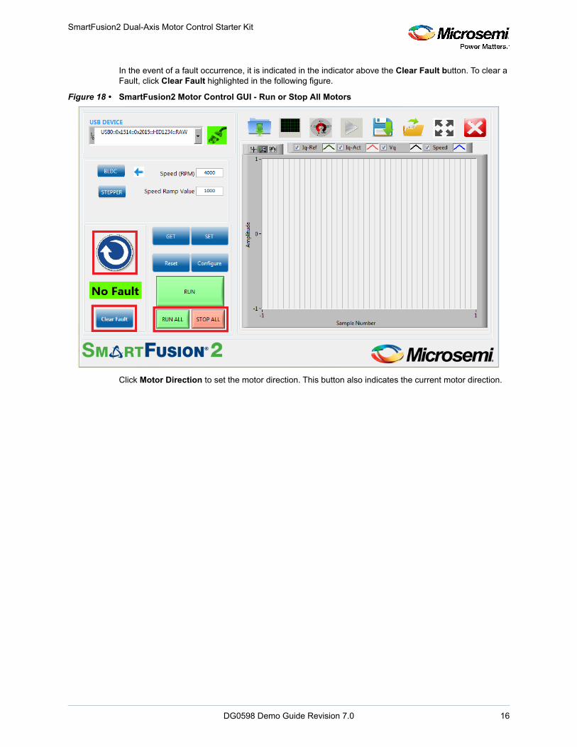
4. Click Run All to run all the motors and click Stop All to stop all the running motors. These buttons are highlighted in the following figure.
DG0598 Demo Guide Revision 7.0 15
SmartFusion2 Dual-Axis Motor Control Starter Kit
In the event of a fault occurrence, it is indicated in the indicator above the Clear Fault button. To clear a Fault, click Clear Fault highlighted in the following figure.
Figure 18 • SmartFusion2 Motor Control GUI - Run or Stop All Motors
Click Motor Direction to set the motor direction. This button also indicates the current motor direction.
DG0598 Demo Guide Revision 7.0 16

SmartFusion2 Dual-Axis Motor Control Starter Kit
5. The GUI automatically plots waveforms when motor starts running. The plotting can be paused by clicking the pause button highlighted in the following figure.
Figure 19 • SmartFusion2 Motor Control GUI - Start Plotting
6. Click Expand Plot Window to display the debug waveforms in a separate window as shown in the following figure. Use the graph palette highlighted in the following figure to expand and analyze the waveforms.
Figure 20 • Plot Waveforms Window
DG0598 Demo Guide Revision 7.0 17

SmartFusion2 Dual-Axis Motor Control Starter Kit
Note: The following figure shows the plots corresponding to the motor axis. All plots are in per unit where a value of 65536 represents the rated value.
Figure 21 • Plot Waveforms Window with Options
7. Right-click on the plot menu to invoke the following options:a. Click next to each plot to use the available options.
b. Use the graph palette highlighted in Figure 20, page 17 to move cursors, zoom, or to pan the dis-play. The graph palette appears with the following options, in order from left to right:
• Pointer Tool: Changes cursor mode to basic pointer• Zoom: Zooms in and out of the display.• Panning Tool: Picks up the plot and moves it around the display.
8. Click Close Zoom view to close the waveforms window.
DG0598 Demo Guide Revision 7.0 18

SmartFusion2 Dual-Axis Motor Control Starter Kit
9. To view the motor speed on a tachometer dial, click RPM and Current as highlighted in the following figure.
Figure 22 • SmartFusion2 Motor Control GUI - Displaying Speed and Current
DG0598 Demo Guide Revision 7.0 19

SmartFusion2 Dual-Axis Motor Control Starter Kit
10. Click Save Waveform to save the current waveform in the GUI as a.tdms file. The saved waveform can be reloaded by using the Load Waveform option and loading the.tdms file.
Figure 23 • SmartFusion2 Motor Control GUI - Saving and Loading Waveforms
2.8 Running Stepper MotorsThis design runs stepper motors in Continuous Mode and Position Mode:
Note: The Continuous Mode is selected by default.
DG0598 Demo Guide Revision 7.0 20

SmartFusion2 Dual-Axis Motor Control Starter Kit
2.8.1 Continuous ModeIn Continuous mode, the motor rotates continuously in the speed that is set by the user. Click Stop to stop the running motor.
1. Click Stepper to select the stepper motor. 2. Verify that the Speed mode option is selected.3. Click GET to see the current parameters. Click Configure to open a list of configurable parameters.
Figure 24 • SmartFusion2 Motor Control GUI - Stepper Motor Window
4. Click Reset to reset all the stepper parameters to their default values, and click SET to enter these values into the system.
5. Click RUN to run the motor with the current parameters.6. Select step resolution value from the Step Resolution drop-down list.7. Enter a speed value between 1 and 200 RPM in Speed (RPM) and click SET.
Note: It is not necessary to stop the motor to change motor speed or the step resolution.
Note: To change the direction of the motor, click Motor Direction.
8. To increase motor torque, increase the current reference and click SET.
CAUTION: Increasing the current scaling value increases the motor current and the motor gets heated if run for a long time.
9. Click STOP to stop the motor.
2.8.2 Position ModeIn Position mode, the motor rotates and stops as per the command steps. It rotates in the speed that is set by the user.
1. Select Position mode option and click SET. 2. Enter the required (absolute) position in Command Steps.
a. The motor provided with the kit has a step number of 200 by default. To run the motor through one revolution, enter 200 in Command Steps.
b. Click SET.
c. Click RUN. The motor runs through the specified number of steps.
DG0598 Demo Guide Revision 7.0 21

SmartFusion2 Dual-Axis Motor Control Starter Kit
• In the Position mode, the motor moves through a fixed number of steps after which the motor stops rotating, but remains energized.
• To move to a different position, enter the new position and click SET.• Click STOP to de-energize the motor. When the motor is de-energized, the current position is
lost.
Plotting debug parameters by clicking Plot Waveforms, displays Id PI output as plot 0, d-axis motor current (Id) as plot 1, the number of steps moved (step count) as plot 2, and the angle generated as plot 3. The following figure shows the GUI in position mode.
Figure 25 • SmartFusion2 Motor Control GUI - Stepper Motor in Position Mode
The motor runs at the speed set by the user in Speed (RPM) through the number of steps entered in Command Steps as shown in the preceding figure.
DG0598 Demo Guide Revision 7.0 22

SmartFusion2 Dual-Axis Motor Control Starter Kit
3. Click Configure to open the Configure Stepper Motor Parameters window, as shown in the following figure.
Figure 26 • Configure Stepper Motor Parameters Window
4. Click STOP to stop the motor/de-energize the motor.5. Click EXIT to exit the SmartFusion2 Motor Control GUI.
DG0598 Demo Guide Revision 7.0 23

SmartFusion2 Dual-Axis Motor Control Starter Kit
2.9 Register Dump FeatureThe register dump feature generates a csv file with data to be programmed in each FPGA register, which is calculated based on motor configuration inputs.
1. Click the icon marked in the following figure to open the Register Dump window.
Figure 27 • Register Dump window
DG0598 Demo Guide Revision 7.0 24

SmartFusion2 Dual-Axis Motor Control Starter Kit
2. The following figure shows the BLDC tab of the register dump window. The Save to File button opens a dialog box to specify the location and the name of the csv file. The generated csv file contains only the data corresponding to the BLDC blocks.
Figure 28 • Register Dump window—BLDC Tab
DG0598 Demo Guide Revision 7.0 25

SmartFusion2 Dual-Axis Motor Control Starter Kit
3. The following figure shows the Stepper tab of the register dump window. The Save to File button opens a dialog box to specify the location and the name of the csv file. The generated csv file contains only the data corresponding to the stepper blocks.
Figure 29 • Register Dump window—Stepper Tab
DG0598 Demo Guide Revision 7.0 26

SmartFusion2 Dual-Axis Motor Control Starter Kit
4. The following figure shows a sample csv file, which contains data calculated based on the inputs provided in the register dump window.
Figure 30 • Sample Csv File
DG0598 Demo Guide Revision 7.0 27

Appendix: Jumper Settings
DG0598 Demo Guide Revision 7.0 28
3 Appendix: Jumper Settings
The following table lists the jumpers that are required to be set on the SmartFusion2 Starter Kit board.
The following figure shows the Jumpers on SmartFusion2 Starter Kit.
Figure 31 • Jumpers on SmartFusion2 Starter Kit
Table 2 • Jumper Settings on the SmartFusion2 Starter Kit Board
Jumper Function Default Settings Notes
Power Supply
J23 SOM power source 1-3 Closed On-board power to SOM
J22 JTAG Mode 3-4 Closed JTAG VPP to 3.3 V
J7, J13 Encoder – Single Ended selection Open To be set for single ended encoder
J8 Encoder – Differential selection Open To be set for differential encoder
J19 Shunt resistor for power measurement Open Voltage can be measured across shunt
J11 Encoder Open Port to connect encoder

Appendix: Connecting the Motor Terminals
4 Appendix: Connecting the Motor Terminals
4.1 BLDC Motor ConnectionsThe following steps describe how to connect to the BLDC motor:
1. Identify and isolate the BLDC Motor Terminals (set of 3) and Hall Sensor Terminals (set of 5), as shown in the following figure. These terminals are tied together.
2. Connect the BLDC Motor Terminals to the three pin plug.3. Connect the Hall Sensor Terminals to the five pin plug.
Figure 32 • Wiring Diagram for BLDC Motor Connectors
Yellow W phase
Red V phase
Black U phase
Red +5V
Black GND
Blue H1
Green H2
White H3
BLDC Motor(QBL 4208-41-04-006)
BLDC Motor Terminals (AWG20)
Hall Sensor Terminals (AWG26)
DG0598 Demo Guide Revision 7.0 29

Appendix: Connecting the Motor Terminals
4.1.1 Stepper Motor ConnectionsThe stepper motor has four terminals. The motor terminals of the stepper motor must be connected to the four pin plug, as shown in the following figure.
Figure 33 • Wiring Diagram for Stepper Motor Connectors
Red - V
Green - W
Black – PHS 4
Blue - U
Stepper MotorQSH 4218-35-10-027
DG0598 Demo Guide Revision 7.0 30