smartfusion2® arm cortex-m3 lab guide
TRANSCRIPT

SmartFusion2® ARM Cortex-M3 Lab Guide

SmartFusion2 ARM Cortex-M3 Lab Guide
Page 2 of 75 v1.2
Microchip FPGA BU, San Jose, CA 95134
© 2021 Microchip Corporation. All rights reserved.
Printed in the United States of America
Release: March 2021
Microchip makes no warranties with respect to this documentation and disclaims any implied warranties of
merchantability or fitness for a particular purpose. Information in this document is subject to change without notice.
Microchip assumes no responsibility for any errors that may appear in this document.
Trademarks
Microchip, PolarFire®SoC, PolarFire®, SmartFusion®2, IGLOO®2, RTG4™ and the associated logos are trademarks or
registered trademarks of Microchip Corporation. All other trademarks and service marks are the property of their
respective owners.

SmartFusion2 ARM Cortex-M3 Lab Guide
Page 3 of 75 v1.2
Table of Contents
SmartFusion2® ARM Cortex-M3 Lab Guide ................................................................................................... 1
Introduction ................................................................................................................................................ 4
Components of SmartFusion2® Device Used ................................................................................................. 5
Tutorial Requirements ................................................................................................................................. 5
Software Requirements ..........................................................................................................................................5
Hardware Requirements ........................................................................................................................................6
Extracting the source files ............................................................................................................................ 6
Step 1 – Creating a Libero® SoC Project ........................................................................................................ 6
Launching Libero® SoC ............................................................................................................................................6
Checking Tool Profiles and IP Cores .........................................................................................................................7
Creating the Libero® SoC Project .............................................................................................................................7
Step 2 – Configuring the SmartFusion2® MSS with System Builder ................................................................ 9
Step 3 – Constraining the Design ................................................................................................................ 27
Importing an IO Constraint file.............................................................................................................................. 27
Generating Timing Constraints .............................................................................................................................. 29
Step 4 – Synthesis and Layout .................................................................................................................... 30
Step 5 – Running the Application ............................................................................................................... 33
Step 6 – Generating Sample Projects and Exporting the Firmware Configuration Files ................................ 34
Generating sample projects .................................................................................................................................. 34
Exporting firmware configuration files and firmware drivers ................................................................................. 37
Step 7 - Debugging with SoftConsole v6.5 .................................................................................................. 41
Running the CorePWM slow blink application ....................................................................................................... 41
Confirming the SoftConsole v6.5 Project Settings .................................................................................................. 49
Building the Project .............................................................................................................................................. 54
Debugging with SoftConsole ................................................................................................................................. 55
Step 8 - Running the RTC_time application (time permitting)...................................................................... 63
Step 9 - Debugging code running from the SmartFusion2® eNVM ............................................................... 68
Building the project with the Release build configuration ...................................................................................... 68
List of Figures ............................................................................................................................................ 73

SmartFusion2 ARM Cortex-M3 Lab Guide
Page 4 of 75 v1.2
Introduction This tutorial demonstrates how to implement a basic SmartFusion2® Microcontroller Subsystem (MSS) configuration
that includes the GPIO, MMUART_0, the RTC and a soft PWM (CorePWM) in the SmartFusion2® fabric using System
Builder.
The SmartFusion2® MSS_GPIO[8] will be configured as an input. MSS_GPIO[8] will be connected to one of the switches
on the SmartFusion2® SMF2000. The fabric PWM[8:1] will be configured as 16 bit PWM; outputs will drive LEDs on the
SmartFusion2® SMF2000;
After completing this tutorial, you will be familiar with the following:
• Using a Tcl script to create a Libero® SoC project
• Using System Builder to configure the SmartFusion2® MSS, add fabric peripherals and generate the design
• Constraining the design for synthesis and layout
• Synthesize the SmartFusion2® design with Synplify Pro ME
• Run layout
• Generate a bitstream
• Program the SmartFusion2® silicon on the SMF2000 board
• Creating firmware configuration files and Sample projects from Libero® SoC
• Using SoftConsole v6.5 to create and debug SmartFusion2® applications
SMF2000 board
Online Reference Manual:
https://wiki.trenz-electronic.de/display/PD/TEM0001+TRM
Schematics:
http://www.trenz-electronic.de/fileadmin/docs/Trenz_Electronic/Modules_and_Module_Carriers/2.5x6.15/TEM0001/REV01/Documents/SCH-TEM0001-01-010C.PDF

SmartFusion2 ARM Cortex-M3 Lab Guide
Page 5 of 75 v1.2
Figure 1 - SmartFusion2® Block Diagram
Components of SmartFusion2® Device Used This tutorial uses the SmartFusion2® Cortex-M3, the MSS GPIO, MMUART_0, the RTC blocks and the FPGA fabric.
Tutorial Requirements
Software Requirements
• Microsemi Libero® SoC v12.6
• Synplify Pro Q-2020.03M
• Identify Debugger Q-2020.03M
• FlashPro Express v12.6
• Microchip SoftConsole v6.5
• Serial terminal program, such as PuTTY or TeraTerm
SmartFusion2® MSS Component versions
The table below lists the version of the SmartFusion2® MSS which must be used.
Libero® SoC Version SmartFusion2® MSS version System Builder
12.6 1.1.500 1.0 Table 1 – SmartFusion2® MSS component versions

SmartFusion2 ARM Cortex-M3 Lab Guide
Page 6 of 75 v1.2
Hardware Requirements This tutorial targets the Trenz Board SMF2000 with SmartFusion2® on it. The free Libero® SoC Silver license can be used
for this tutorial. Modelsim®Pro (mixed language simulation) is supported by a Silver license generated after May 22nd
2020.
Extracting the source files Use SMF2000_Cortex_M3_PWM_lab_sources.zip to extract the required lab files to the C:> or D:>\Microsemiprj folder
on the HDD of your PC. Confirm that a folder named SMF2000_Cortex_M3_PWM_lab_sources containing 3 sub-folders
named constraints, hex_File and Script were extracted.
Step 1 – Creating a Libero® SoC Project In this step, you will create a Libero® SoC v12.6 project.
Launching Libero® SoC 1. Click Start > Programs > Microsemi Libero SoC v12.6 > Libero SoC v12.6 or click the shortcut on your desktop. The
Libero® SoC Project Manager will open.
Figure 2 - Libero® SoC Project Manager

SmartFusion2 ARM Cortex-M3 Lab Guide
Page 7 of 75 v1.2
Checking Tool Profiles and IP Cores
2. Click Project > Tool Profiles from the Libero® SoC menu to open the Tool Profiles dialog box.
Verify that the following tool profiles exist:
• Synthesis: Synplify Pro® ME contained in <Libero_v12.6_installation>\SynplifyPro\bin\synplify_pro.exe
• Simulation: Modelsim® ME Pro contained in < Libero_v12.6_installation>\ModelsimPro\win32acoem\modelsim.exe
3. Click OK to close the Tool Profiles dialog box.
4. Open the Libero® SoC IP catalog (View > Windows > Catalog). If the message New Cores are available appears at
the bottom of the catalog, click Download them now to download the cores.
Figure 3 - IP Catalog indicating new cores are available
Creating the Libero® SoC Project Use the Tcl script contained in the Scripts folder to create the Libero® SoC project.
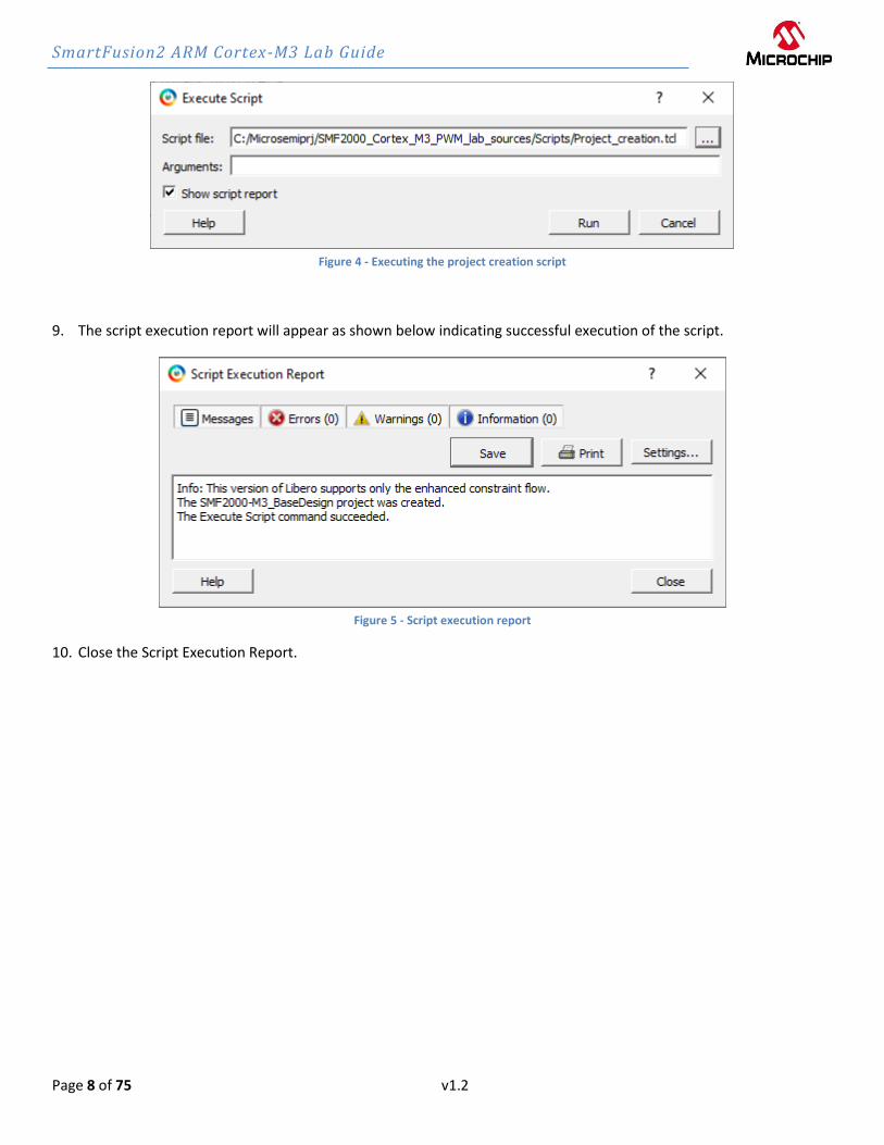
5. Select Project > Execute Script from the Libero® SoC menu. The Execute Script dialog box will open.
6. Click the Browse button ( ) to open the Select the script file dialog.
7. Navigate to the C:\Microsemiprj\SMF2000_Cortex_M3_PWM_lab_sources\Scripts\ folder.
Select Project_creation.tcl then click Open.
8. Click Run in the Execute Script dialog box to execute the script.
SmartFusion2 ARM Cortex-M3 Lab Guide
Page 8 of 75 v1.2
Figure 4 - Executing the project creation script
9. The script execution report will appear as shown below indicating successful execution of the script.
Figure 5 - Script execution report
10. Close the Script Execution Report.

SmartFusion2 ARM Cortex-M3 Lab Guide
Page 9 of 75 v1.2
Step 2 – Configuring the SmartFusion2® MSS with System Builder In this step, you will configure the SmartFusion2® Microcontroller Subsystem (MSS) using System Builder.
1. Select the Libero® SoC Design Flow tab. Expand Create Design and double-click System Builder.
Figure 6 - Libero® SoC Design Flow tab
2. Enter SF2_MSS when prompted for a name for your system.
Figure 7 - Entering a name for System Builder

SmartFusion2 ARM Cortex-M3 Lab Guide
Page 10 of 75 v1.2
3. System Builder will open with the “System Builder - Device Features” page visible as shown below.
Figure 8 – SmartFusion2® System Builder Device Features page
4. Enter the following on the “System Builder - Device Features” page:
• Memory
o MSS External Memory un-checked (default)
o MSS On-chip Flash Memory (eNVM) checked
• Microcontroller Options
o Watchdog Timer un-checked (default)
o Peripheral DMA un-checked (default)
o Real Time Counter checked

SmartFusion2 ARM Cortex-M3 Lab Guide
Page 11 of 75 v1.2
Figure 9 - System Builder Device Features after selections
5. Click Next. The “System Builder – Memory” page will open.
Figure 10 - System Builder Memories page
SmartFusion2 ARM Cortex-M3 Lab Guide
Page 12 of 75 v1.2
6. Select Data Storage under Available client types (highlighted in the figure above) then click Add to System. This will
create a partition in the SmartFusion2® Embedded Non-volatile memory (eNVM) which will be used to store the
Cortex-M3 application program.
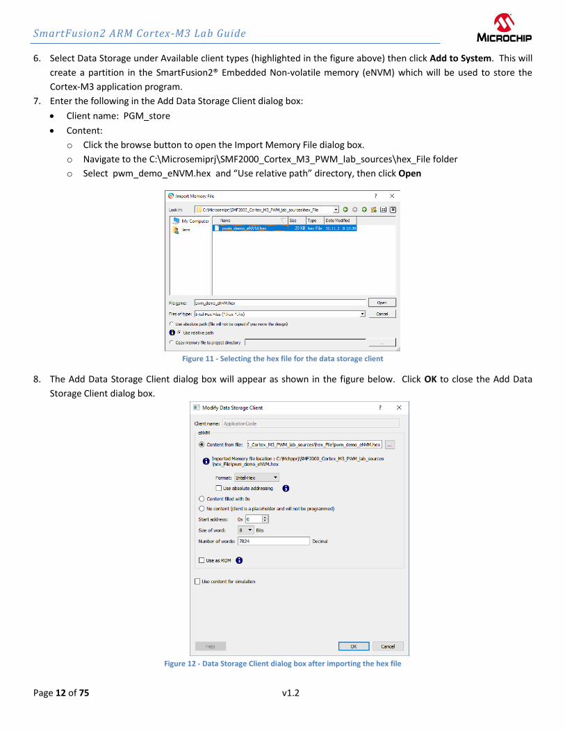
7. Enter the following in the Add Data Storage Client dialog box:
• Client name: PGM_store
• Content:
o Click the browse button to open the Import Memory File dialog box.
o Navigate to the C:\Microsemiprj\SMF2000_Cortex_M3_PWM_lab_sources\hex_File folder
o Select pwm_demo_eNVM.hex and “Use relative path” directory, then click Open
Figure 11 - Selecting the hex file for the data storage client
8. The Add Data Storage Client dialog box will appear as shown in the figure below. Click OK to close the Add Data
Storage Client dialog box.
Figure 12 - Data Storage Client dialog box after importing the hex file

SmartFusion2 ARM Cortex-M3 Lab Guide
Page 13 of 75 v1.2
9. The client will be visible in the System Builder Memories page.
Figure 13 - System Builder Memories page after adding the data storage client
10. Click Next. The “System Builder – Peripherals” page will open. Here you can enable or disable MSS peripherals and
add fabric peripherals. Configure peripherals by clicking the wrench symbol ( ). The number of fabric
peripherals used can be changed by editing the number in the Quantity column.
Figure 14 - System Builder Peripherals page
11. Disable the MM_UART_1, MSS_I2C_0, MSS_I2C_1, MSS_SPI_0 and MSS_SPI_1 peripherals by clicking the box in the
Enable column.

SmartFusion2 ARM Cortex-M3 Lab Guide
Page 14 of 75 v1.2
12. Click the wrench symbol ( ) next to the MM_UART_0 peripheral to open the MM_UART_0 Configurator.
Verify the “Connect to IO” configuration. Click OK to close the configurator.
Figure 15 - MM_UART_0 configurator
13. Enable the MSS_GPIO peripheral by clicking the box under the Enable column.
14. Click the wrench symbol ( ) next to the MSS_GPIO peripheral to open the MSS GPIO Configurator. Configure the
GPIOs as shown below.
• Set/Reset Definition: accept default settings
• Configure GPIO[31:0] per the table below:
GPIO ID Direction Package Pin Connectivity
GPIO[0:7] Not Used NA NA
GPIO_8 Input NA FABRIC_A
GPIO_[9:31] Not Used NA NA Table 3 – SmartFusion2® GPIO configuration

SmartFusion2 ARM Cortex-M3 Lab Guide
Page 15 of 75 v1.2
Figure 16 - SmartFusion2® GPIO Configuration
15. Click OK to close the MSS GPIO Configurator.
SmartFusion2 ARM Cortex-M3 Lab Guide
Page 16 of 75 v1.2
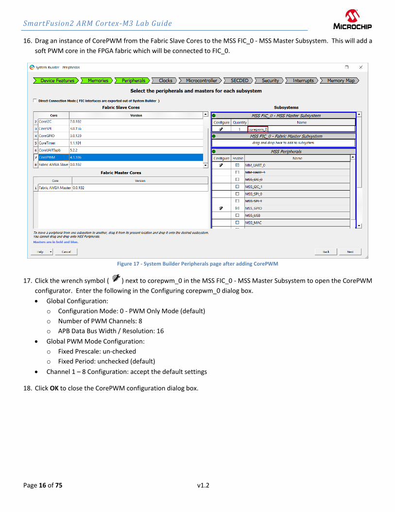
16. Drag an instance of CorePWM from the Fabric Slave Cores to the MSS FIC_0 - MSS Master Subsystem. This will add a
soft PWM core in the FPGA fabric which will be connected to FIC_0.
Figure 17 - System Builder Peripherals page after adding CorePWM
17. Click the wrench symbol ( ) next to corepwm_0 in the MSS FIC_0 - MSS Master Subsystem to open the CorePWM
configurator. Enter the following in the Configuring corepwm_0 dialog box.
• Global Configuration:
o Configuration Mode: 0 - PWM Only Mode (default)
o Number of PWM Channels: 8
o APB Data Bus Width / Resolution: 16
• Global PWM Mode Configuration:
o Fixed Prescale: un-checked
o Fixed Period: unchecked (default)
• Channel 1 – 8 Configuration: accept the default settings
18. Click OK to close the CorePWM configuration dialog box.

SmartFusion2 ARM Cortex-M3 Lab Guide
Page 17 of 75 v1.2
Figure 18 - corepwm_0 configuration
Note: additional information about CorePWM and the configuration parameters is available in the CorePWM handbook.
The CorePWM handbook can be accessed from the CorePWM Configurator by clicking Help.

SmartFusion2 ARM Cortex-M3 Lab Guide
Page 18 of 75 v1.2
19. Click Next. The “System Builder – Clocks” page will open. Use this page to specify the clock source and clock
frequencies used in the design. Enter the following on the Clock tab:
• System Clock: Select On-chip 25/50 MHz RC Oscillator from the pull-down menu
• M3_CLK: 100 MHz (default)
• APB_0 CLK: M3_CLK/1 (100 MHz) (default)
• APB_1 CLK: M3_CLK/1 (100 MHz) (default)
• FIC_0_CLK: M3_CLK/2 (50 MHz)
These frequencies were chosen to maximize the speed of the Cortex-M3 microcontroller.
Figure 19 – Configuring the MSS clocks

SmartFusion2 ARM Cortex-M3 Lab Guide
Page 19 of 75 v1.2
20. Click Next. The “System Builder - Microcontroller” page will open. This page has multiple tabs, which allow
configuring the Cortex-M3 microcontroller, the Cache Controller and the AHB Bus Matrix.
Figure 20 - System Builder Microcontroller options page

SmartFusion2 ARM Cortex-M3 Lab Guide
Page 20 of 75 v1.2
21. Select the Real Time Counter tab in the System Builder - Microcontroller pane. This is where options for the RTC are
set.
22. Select the On-chip 1 MHz RC Oscillator as the RTC clock source from the pull-down menu in the Clock Source field on
the Real Time Counter tab. This option matches the RTC sample projects available in the Firmware Catalog.
23. Accept the default settings for the Wakeup Interrupt and the RTC_MATCH signal.
Figure 21 - System Builder Microcontroller options page after selecting the RTC clock source
24. Although we won’t be making any other changes, take a moment to become familiar with the contents of the other
tabs (Cortex-M3, Cache Controller, AHB Bus Matrix).
25. Click Next to accept the default settings on the Microcontroller page.

SmartFusion2 ARM Cortex-M3 Lab Guide
Page 21 of 75 v1.2
26. The “System Builder – SECDED” (Single Error Correct / Double Error Detect) page will open. Use this page to enable
SECDED for various memory blocks within the SmartFusion2® MSS. Although we won’t be using SECDED for this
design, take a moment to become familiar with the contents of this page.
Figure 22 - System Builder SECDED options page
27. Accept the default settings on the page and click Next.
28. The “System Builder – Security” page will open. This page is used to set the Master to Slave Read/Write access for
devices that support Data Security features. The SmartFusion2® devices on the SMF2000 kit does not support these
security features, so these options will be grayed out.
29. Click Next to accept the default settings.

SmartFusion2 ARM Cortex-M3 Lab Guide
Page 22 of 75 v1.2
30. The “System Builder – Interrupts” page will open. This page displays interrupt connections generated from attached
fabric peripherals. The CorePWM TACHINT interrupt will be visible as shown in the figure below.
Figure 23 - CorePWM TACHINT interrupt

SmartFusion2 ARM Cortex-M3 Lab Guide
Page 23 of 75 v1.2
31. Click Next. The “System Builder – Memory Map” page will open. This page displays the addresses of fabric
peripherals. The address of CorePWM will be visible. Up to six different memory regions can be assigned to each FIC in the
MSS memory map. In this design, two memory regions (0x30000000 and 0x50000000) are assigned to FIC_0 for the interface to
the FPGA fabric and CorePWM.
Figure 24 - Fabric memory map
32. Click Finish.
33. Confirm that the message “’SF2_MSS_sb’” was generated successfully” appears in the Libero® SoC Message tab.
Figure 25 - Message tab after successfully generating the MSS design
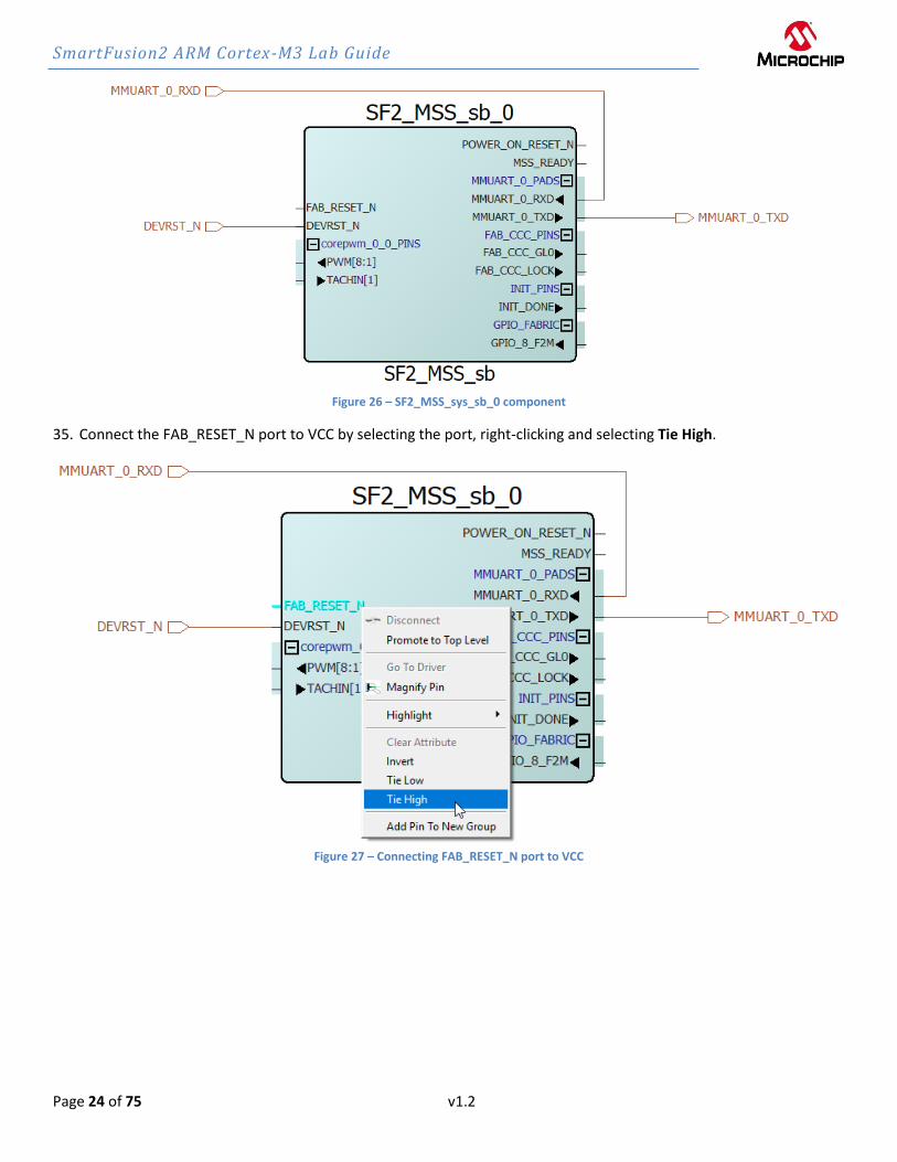
34. A component named SF2_MSS_sb_0 will be visible in the SmartDesign canvas as shown below. If necessary, click
the SF2_MSS tab to display the SmartDesign canvas.
SmartFusion2 ARM Cortex-M3 Lab Guide
Page 24 of 75 v1.2
Figure 26 – SF2_MSS_sys_sb_0 component
35. Connect the FAB_RESET_N port to VCC by selecting the port, right-clicking and selecting Tie High.
Figure 27 – Connecting FAB_RESET_N port to VCC
SmartFusion2 ARM Cortex-M3 Lab Guide
Page 25 of 75 v1.2
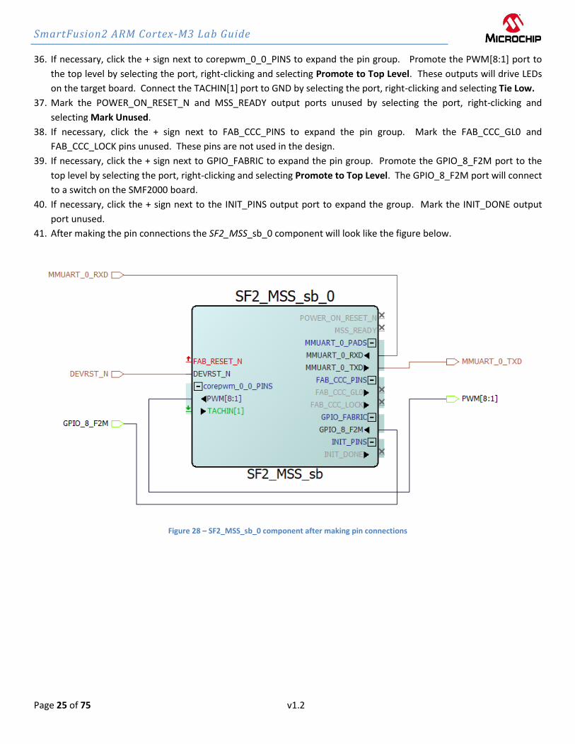
36. If necessary, click the + sign next to corepwm_0_0_PINS to expand the pin group. Promote the PWM[8:1] port to
the top level by selecting the port, right-clicking and selecting Promote to Top Level. These outputs will drive LEDs
on the target board. Connect the TACHIN[1] port to GND by selecting the port, right-clicking and selecting Tie Low.
37. Mark the POWER_ON_RESET_N and MSS_READY output ports unused by selecting the port, right-clicking and
selecting Mark Unused.
38. If necessary, click the + sign next to FAB_CCC_PINS to expand the pin group. Mark the FAB_CCC_GL0 and
FAB_CCC_LOCK pins unused. These pins are not used in the design.
39. If necessary, click the + sign next to GPIO_FABRIC to expand the pin group. Promote the GPIO_8_F2M port to the
top level by selecting the port, right-clicking and selecting Promote to Top Level. The GPIO_8_F2M port will connect
to a switch on the SMF2000 board.
40. If necessary, click the + sign next to the INIT_PINS output port to expand the group. Mark the INIT_DONE output
port unused.
41. After making the pin connections the SF2_MSS_sb_0 component will look like the figure below.
Figure 28 – SF2_MSS_sb_0 component after making pin connections

SmartFusion2 ARM Cortex-M3 Lab Guide
Page 26 of 75 v1.2
42. Execute a Design Rules Check by clicking the Checkmark icon.
Figure 29– Execute Design Rules Check
43. Verify the correctness of the SmartDesign Component:
• Check Messages window for “SmartDesign 'SF2_MSS' design rules check succeeded”.
44. Generate the design by clicking SmartDesign > Generate Component or by clicking the Generate Component icon
on the SmartDesign toolbar ( ).
45. The message “'SF2_MSS’ was generated successfully” will appear in the Libero® SoC Message window indicating the
design was generated without any errors.
Figure 30 - Libero® SoC Message window after generating the design
40. Close the design (File > Close SF2_MSS).
SmartFusion2 ARM Cortex-M3 Lab Guide
Page 27 of 75 v1.2
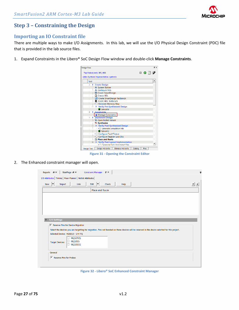
Step 3 – Constraining the Design
Importing an IO Constraint file There are multiple ways to make I/O Assignments. In this lab, we will use the I/O Physical Design Constraint (PDC) file
that is provided in the lab source files.
1. Expand Constraints in the Libero® SoC Design Flow window and double-click Manage Constraints.
Figure 31 - Opening the Constraint Editor
2. The Enhanced constraint manager will open.
Figure 32 - Libero® SoC Enhanced Constraint Manager

SmartFusion2 ARM Cortex-M3 Lab Guide
Page 28 of 75 v1.2
3. Click Import on the I/O Attributes tab to open the Import Files dialog box. Navigate to the
C:\Microsemiprj\SMF2000_Cortex_M3_PWM_lab_sources\constraints folder.
Select io_constraints.pdc then click Open.
Figure 33 - Importing the I/O constraint file
4. The file will be visible on the I/O Attributes tab of the Constraint Manager.
Double-click io_constraints.pdc to open the file in the Libero® SoC text editor. Scroll in the file to become familiar
with the syntax. The constraint set_io sets the pin number and I/O specific attributes. The # symbol is a comment.
Note the internal pull-up setting for the GPIO_8_F2M signal pin.
# USER_BTN
set_io GPIO_8_F2M -pinname B19 -fixed yes -iostd LVCMOS33 -RES_PULL Up
5. Close the editor (File > Close io_constraints.pdc).
6. Check the box under Place and Route for constraint\io\io_constraints.pdc in the I/O Attributes tab to use the PDC
constraint file for layout.
7. Click Save to save all changes in Constraint Manager, select YES in Warning message about flow invalidation.
Figure 34 - Selecting and saving the I/O constraint file for layout

SmartFusion2 ARM Cortex-M3 Lab Guide
Page 29 of 75 v1.2
Generating Timing Constraints In this step, you derive timing constraints for the design. Libero® SoC can generate timing constraints for known blocks
(such as the RC oscillators and the PLLs) automatically.
7. Select the Timing tab in the Constraint manager window. Double-click Derive Constraints.
Figure 35 - Deriving Timing Constraints
8. Click on Yes in the Message window to automatically associate the derived constraints SDC file to the ‘Synthesis’,
‘Place and Route’ and ‘Timing Verification’.
Figure 36 - Message Window
9. A constraint file named SF2_MSS_derived_constraints.sdc will be visible. Double-click on the file name to open the
file in the Libero® SoC text editor to become familiar with the content.
Figure 37 - Derived Timing Constraints

SmartFusion2 ARM Cortex-M3 Lab Guide
Page 30 of 75 v1.2
Step 4 – Synthesis and Layout
In this step, you will use the push-button flow to synthesize the design with Synplify Pro, run layout and generate the
programming file
1. Double-click the Generate Bitstream in the Design Flow window to synthesize the design, run layout using the
I/O constraints that were created and generate the programming file.
Figure 38 - Generate Bitstream

SmartFusion2 ARM Cortex-M3 Lab Guide
Page 31 of 75 v1.2
The design implementation tools will run in batch mode. Successful completion of a design step will be indicated by a
green check mark next to the Implement Design item in the Design Flow window.
Figure 39 - Successful completion of design implementation

SmartFusion2 ARM Cortex-M3 Lab Guide
Page 32 of 75 v1.2
2. The Reports tab will display reports for the tools used to implement the design.
Figure 40 - Reports tab after implementing the design
4.Connect the SMF2000 board using a Micro-USB cable to the PC USB port (board power is provided from PC USB port).
The Window’s Device Manager should display the following entries (port number may differ depending on your PC):
Figure 41 - Device Manager
SmartFusion2 ARM Cortex-M3 Lab Guide
Page 33 of 75 v1.2
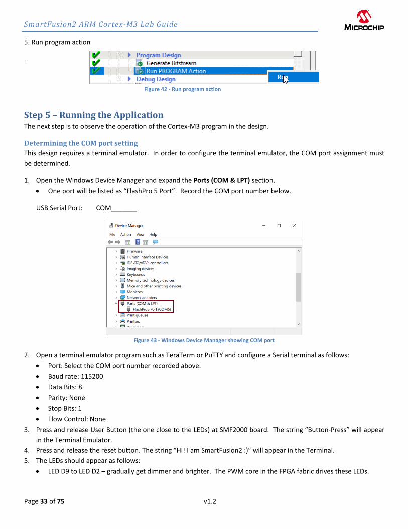
5. Run program action
.
Figure 42 - Run program action
Step 5 – Running the Application The next step is to observe the operation of the Cortex-M3 program in the design.
Determining the COM port setting
This design requires a terminal emulator. In order to configure the terminal emulator, the COM port assignment must
be determined.
1. Open the Windows Device Manager and expand the Ports (COM & LPT) section.
• One port will be listed as “FlashPro 5 Port”. Record the COM port number below.
USB Serial Port: COM_______
Figure 43 - Windows Device Manager showing COM port
2. Open a terminal emulator program such as TeraTerm or PuTTY and configure a Serial terminal as follows:
• Port: Select the COM port number recorded above.
• Baud rate: 115200
• Data Bits: 8
• Parity: None
• Stop Bits: 1
• Flow Control: None
3. Press and release User Button (the one close to the LEDs) at SMF2000 board. The string “Button-Press” will appear
in the Terminal Emulator.
4. Press and release the reset button. The string “Hi! I am SmartFusion2 :)” will appear in the Terminal.
5. The LEDs should appear as follows:
• LED D9 to LED D2 – gradually get dimmer and brighter. The PWM core in the FPGA fabric drives these LEDs.

SmartFusion2 ARM Cortex-M3 Lab Guide
Page 34 of 75 v1.2
Step 6 – Generating Sample Projects and Exporting the Firmware Configuration
Files In this step, you will generate sample projects and export the firmware configuration files for the design.
Generating sample projects 1. Expand Handoff Design for Firmware Development on the Design Flow tab. Select Configure Firmware Cores, then
right-click and select Open Interactively.
Figure 44 - Configuring Firmware cores for the design
2. The DESIGN_FIRMWARE tab will open.
Figure 45 - DESIGN FIRMWARE tab
3. Confirm that none of the drivers appears in italics. If any drivers appear in italics, click the check box in the Generate
column for the missing core. Click Yes when prompted about downloading the core.
4. Click Yes in the Download Required dialog box to download any firmware cores that are missing from the IP vault.

SmartFusion2 ARM Cortex-M3 Lab Guide
Page 35 of 75 v1.2
Figure 46 - Downloading missing firmware cores
5. Use the pull-down menu in the SmartFusion2_CMSIS_0 row to select version 2.3.105 if it is not selected.
Figure 47 - Selecting SmartFusion2_CMSIS version 2.3.105
6. Create the CorePWM sample project by selecting CorePWM_Driver_0 on the DESIGN FIRMWARE tab, then right
clicking and selecting Generate Sample Project > Cortex-M3 > SoftConsole v4.0 > PWM slow blink. Note that
SoftConsole v4.0 projects can be opened in SoftConsole v6.5.
Figure 48 - Generating the CorePWM sample project
7. Confirm the following settings in the Generate Sample Options dialog box then click OK:
• Folder: C:\Microsemiprj\SMF2000-M3_BaseDesign\SoftConsole
• Show generation report: checked
Figure 49 – CorePWM slow blink sample project options

SmartFusion2 ARM Cortex-M3 Lab Guide
Page 36 of 75 v1.2
8. The Report dialog box will list all the files generated and the location.
Figure 50 - GPIO Simple Blink project files
9. Click Close to close the Report window.
10. Create the MSS RTC sample project by selecting SmartFusion2_MSS_RTC_Driver_0 on the DESIGN_FIRMWARE tab,
then right clicking and selecting Generate Sample Project > Cortex-M3 > SoftConsole v4.0 > RTC Time.
Figure 51 - Generating the RTC Driver sample project
11. Confirm the following settings in the Generate Sample Options dialog box then click OK:
• Folder: C:\Microsemiprj\SMF2000-M3_BaseDesign\SoftConsole
• Show generation report: checked

SmartFusion2 ARM Cortex-M3 Lab Guide
Page 37 of 75 v1.2
Figure 52 – RTC Time sample project location
12. The Report dialog box will list all the files generated and the location.
Figure 53 - RTC_time project files
13. Click Close to close the Report window.
14. Close the DESIGN_FIRMWARE tab (File > Close DESIGN_FIRMWARE). Select Yes if prompted about saving changes
to DESIGN_FIRMWARE.
Exporting firmware configuration files and firmware drivers The firmware used in a SoftConsole project must match the target hardware configuration. For SmartFusion2® projects,
Libero® SoC generates specific firmware files that are required to ensure that the SoftConsole project matches and is
compatible with the target hardware. The sample projects created in the previous step contain generic firmware files
that may not match the target hardware. In this step, you will export firmware configuration files that match the design
configuration.

SmartFusion2 ARM Cortex-M3 Lab Guide
Page 38 of 75 v1.2
15. Select Export Firmware under Handoff Design for Firmware Development on the Design Flow tab, then right-click
and select Export Firmware… to create the firmware drivers for the design.
Figure 54 - Exporting the firmware configuration files
16. Enter the following in the Export Firmware dialog box then click OK:
• Location: Accept the default location
• Software IDE: select SoftConsole4.0 from the pull-down menu
• Export hardware configuration: Checked
Figure 55 - Export Firmware options

SmartFusion2 ARM Cortex-M3 Lab Guide
Page 39 of 75 v1.2
17. Click OK in the dialog box that indicates the location of the firmware cores.
Figure 56 - Firmware driver location
18. The firmware drivers will be visible on the Libero® SoC Files tab. The Project for selected toolchain and the sample
projects will be visible on the Files tab in the SoftConsole folder. If the projects are not visible, select View > Refresh
Design Hierarchy from the Libero® SoC menu.
Figure 57 - Sample projects on Libero® SoC Files tab

SmartFusion2 ARM Cortex-M3 Lab Guide
Page 40 of 75 v1.2
19. The Data Sheet containing the memory map will be visible in the Libero® SoC Report tab.
Figure 58 – Data Sheet for the design
20. Scroll in the SF2_MSS data sheet and become familiar with the Generated Files, Firmware and Memory Map
sections (click on the hyperlink at the top of the data sheet to move to the section of interest).
21. Select the Memory Map to become familiar with the locations of the peripherals.
What is the address of MMUART_0? ________________
What is the address of corepwm? _________________
22. Minimize Libero® SoC.

SmartFusion2 ARM Cortex-M3 Lab Guide
Page 41 of 75 v1.2
Step 7 - Debugging with SoftConsole v6.5
Running the CorePWM slow blink application In this step, you will launch SoftConsole v6.5, import the sample projects created from Libero® SoC and run the
CorePWM slow blink application from the SmartFusion2® eSRAM.
1. Click Start > Programs > Microsemi > SoftConsole v6.5, or click the shortcut on your desktop. The SoftConsole 6.5
Workspace Launcher may open as shown below.
Figure 59 - SoftConsole 6.5 Workspace Launcher (location shown may differ)
2. Click the browse button in the Workspace Launcher and navigate to the project location into the SoftConsole
subfolder e.g. “C:\Microsemiprj\SMF2000-M3_BaseDesign\SoftConsole” then click OK.
Figure 60 - Selecting the SoftConsole workspace
SmartFusion2 ARM Cortex-M3 Lab Guide
Page 42 of 75 v1.2
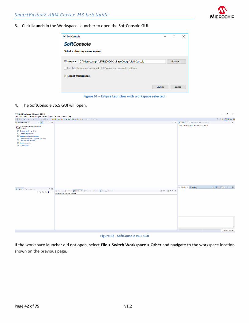
3. Click Launch in the Workspace Launcher to open the SoftConsole GUI.
Figure 61 – Eclipse Launcher with workspace selected.
4. The SoftConsole v6.5 GUI will open.
Figure 62 - SoftConsole v6.5 GUI
If the workspace launcher did not open, select File > Switch Workspace > Other and navigate to the workspace location
shown on the previous page.
SmartFusion2 ARM Cortex-M3 Lab Guide
Page 43 of 75 v1.2
Importing the CorePWM slow blink and RTC Time SoftConsole Projects
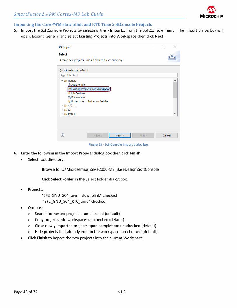
5. Import the SoftConsole Projects by selecting File > Import… from the SoftConsole menu. The Import dialog box will
open. Expand General and select Existing Projects into Workspace then click Next.
Figure 63 - SoftConsole Import dialog box
6. Enter the following in the Import Projects dialog box then click Finish:
• Select root directory:
Browse to C:\Microsemiprj\SMF2000-M3_BaseDesign\SoftConsole
Click Select Folder in the Select Folder dialog box.
• Projects:
“SF2_GNU_SC4_pwm_slow_blink” checked
“SF2_GNU_SC4_RTC_time” checked
• Options:
o Search for nested projects: un-checked (default)
o Copy projects into workspace: un-checked (default)
o Close newly imported projects upon completion: un-checked (default)
o Hide projects that already exist in the workspace: un-checked (default)
• Click Finish to import the two projects into the current Workspace.

SmartFusion2 ARM Cortex-M3 Lab Guide
Page 44 of 75 v1.2
Figure 64 - Importing the sample projects into the workspace

SmartFusion2 ARM Cortex-M3 Lab Guide
Page 45 of 75 v1.2
7. The SoftConsole projects will be visible in the SoftConsole Project Explorer.
Figure 65 - SoftConsole projects in the workspace
8. Close the SF2_GNU_SC4_RTC_time project by selecting the project name in the Project Explorer then right-clicking
and selecting Close Project.

SmartFusion2 ARM Cortex-M3 Lab Guide
Page 46 of 75 v1.2
Importing the firmware configuration files
9. Import the firmware configuration files that were exported from Libero® SoC into the
SF2_GNU_SC4_pwm_slow_blink project by selecting SF2_GNU_SC4_pwm_slow_blink in the Project Explorer then
selecting File > Import from the SoftConsole menu. The Import dialog box will open.
10. Expand the General category in the Import dialog box and select File System and then click Next.
Figure 66 - Importing the firmware configuration files
11. The File system dialog box will open. Click the Browse button. Navigate to the C:\Microsemiprj\SMF2000-M3_BaseDesign\firmware folder and click Select Folder.
12. Enter the following in the File system dialog box:
• From directory:
C:\Microsemiprj\SMF2000-M3_BaseDesign\firmware
• Select
o Click next to the firmware folder in the left window pane to expand it (circled in the figure below) o Make sure the following folders are enabled (checkmark):
▪ CMSIS ▪ drivers ▪ drivers_config ▪ hal
o With firmware folder selected on the left side, un-check “README.txt”, “SF2_MSS_cmsis.svd.xml” and
“SF2_MSS_hw_platform.h” on the right side
• Into Folder: SF2_GNU_SC4_pwm_slow_blink

SmartFusion2 ARM Cortex-M3 Lab Guide
Page 47 of 75 v1.2
Figure 67 - Importing the firmware configuration files into the project
13. Click Finish. Click Yes To All in the Question dialog box when prompted about Overwriting files.
Figure 68 - Question dialog box

SmartFusion2 ARM Cortex-M3 Lab Guide
Page 48 of 75 v1.2
14. The project should appear in the Project Explorer as shown in the figure below.
Figure 69 - SF2_GNU_SC4_pwm_slow_blink after importing the firmware configuration files
15. Double click main.c in the Project Explorer window to open the file in the SoftConsole C/C++ editor. Scroll through
the file to become familiar with it.
Figure 70 - main.c in the SoftConsole editor

SmartFusion2 ARM Cortex-M3 Lab Guide
Page 49 of 75 v1.2
16. Double click platform.h in the Project Explorer window to open the file in the SoftConsole C/C++ editor. Compare
the COREPWM_BASE_ADDR on line 16 to the address recorded on page 40. Modify and save the file if necessary.
Hint: The default address value shown below is incorrect and needs to be updated according to the memory map.
Figure 71 - platform.h in the SoftConsole editor
Confirming the SoftConsole v6.5 Project Settings The next steps to confirm the sample project settings prior to performing a build. SoftConsole supports multiple build
configurations. By default, projects contain two build configurations: Debug and Release. Some project settings apply to
all build configurations while others apply to a specific build configuration.
17. Open the Project Properties dialog box by clicking on the project name (SF2_GNU_SC4_pwm_slow_blink) in the
Project Explorer and selecting Project > Properties.
18. Navigate to C/C++ Build > Settings in the Properties for SF2_GNU_SC4_pwm_slow_blink dialog box.
SmartFusion2 ARM Cortex-M3 Lab Guide
Page 50 of 75 v1.2
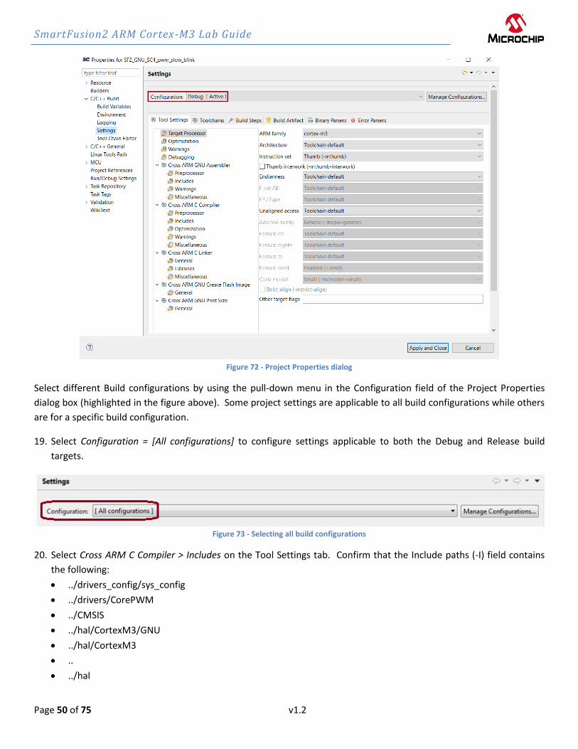
Figure 72 - Project Properties dialog
Select different Build configurations by using the pull-down menu in the Configuration field of the Project Properties
dialog box (highlighted in the figure above). Some project settings are applicable to all build configurations while others
are for a specific build configuration.
19. Select Configuration = [All configurations] to configure settings applicable to both the Debug and Release build
targets.
Figure 73 - Selecting all build configurations
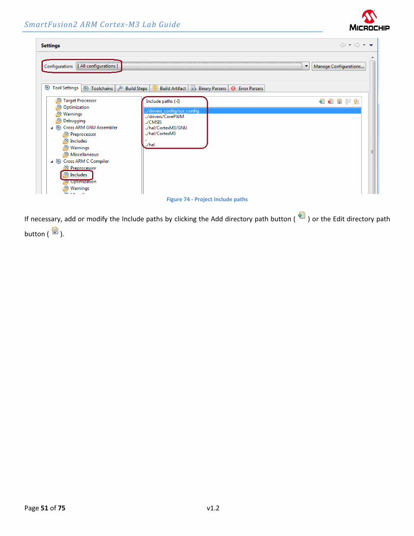
20. Select Cross ARM C Compiler > Includes on the Tool Settings tab. Confirm that the Include paths (-I) field contains
the following:
• ../drivers_config/sys_config
• ../drivers/CorePWM
• ../CMSIS
• ../hal/CortexM3/GNU
• ../hal/CortexM3
• ..
• ../hal
SmartFusion2 ARM Cortex-M3 Lab Guide
Page 51 of 75 v1.2
Figure 74 - Project Include paths
If necessary, add or modify the Include paths by clicking the Add directory path button ( ) or the Edit directory path
button ( ).
SmartFusion2 ARM Cortex-M3 Lab Guide
Page 52 of 75 v1.2
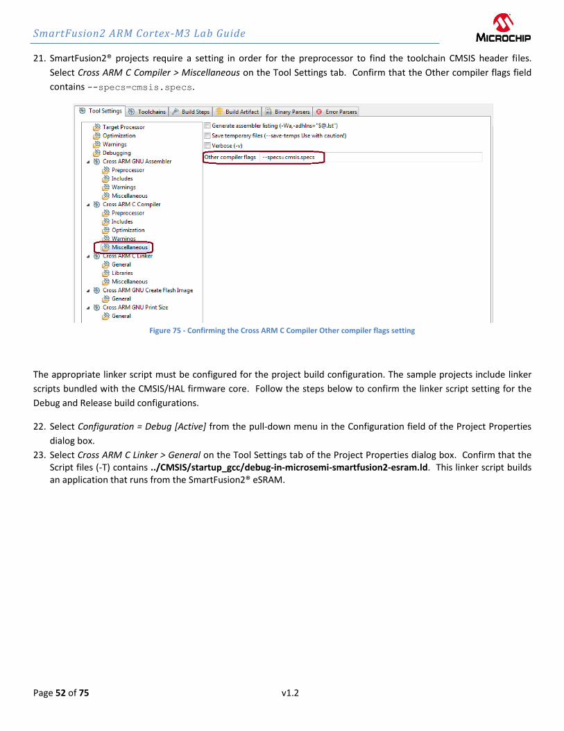
21. SmartFusion2® projects require a setting in order for the preprocessor to find the toolchain CMSIS header files.
Select Cross ARM C Compiler > Miscellaneous on the Tool Settings tab. Confirm that the Other compiler flags field
contains --specs=cmsis.specs.
Figure 75 - Confirming the Cross ARM C Compiler Other compiler flags setting
The appropriate linker script must be configured for the project build configuration. The sample projects include linker
scripts bundled with the CMSIS/HAL firmware core. Follow the steps below to confirm the linker script setting for the
Debug and Release build configurations.
22. Select Configuration = Debug [Active] from the pull-down menu in the Configuration field of the Project Properties
dialog box.
23. Select Cross ARM C Linker > General on the Tool Settings tab of the Project Properties dialog box. Confirm that the Script files (-T) contains ../CMSIS/startup_gcc/debug-in-microsemi-smartfusion2-esram.ld. This linker script builds an application that runs from the SmartFusion2® eSRAM.

SmartFusion2 ARM Cortex-M3 Lab Guide
Page 53 of 75 v1.2
Figure 76 - Debug configuration linker script
24. Select Configuration = Release from the pull-down menu in the Configuration field of the Project Properties dialog
box.
25. Select Cross ARM C Linker > General on the Tool Settings tab of the Project Properties dialog box and confirm that the Script files (-T) field contains ../CMSIS/startup_gcc/debug-in-microsemi-smartfusion2-envm.ld. This linker script builds an application that runs from the SmartFusion2® eNVM.
Figure 77 - Release configuration linker script
26. After confirming the settings listed in the previous steps, click Apply and Close in the Properties for
SF2_GNU_SC4_pwm_slow_blink dialog box.
SmartFusion2 ARM Cortex-M3 Lab Guide
Page 54 of 75 v1.2
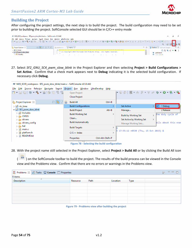
Building the Project After configuring the project settings, the next step is to build the project. The build configuration may need to be set prior to building the project. SoftConsole selected GUI should be in C/C++ entry mode
27. Select SF2_GNU_SC4_pwm_slow_blink in the Project Explorer and then selecting Project > Build Configurations > Set Active. Confirm that a check mark appears next to Debug indicating it is the selected build configuration. If necessary click Debug.
Figure 78 - Selecting the build configuration
28. With the project name still selected in the Project Explorer, select Project > Build All or by clicking the Build All icon
( ) on the SoftConsole toolbar to build the project. The results of the build process can be viewed in the Console
view and the Problems view. Confirm that there are no errors or warnings in the Problems view.
Figure 79 - Problems view after building the project
SmartFusion2 ARM Cortex-M3 Lab Guide
Page 55 of 75 v1.2
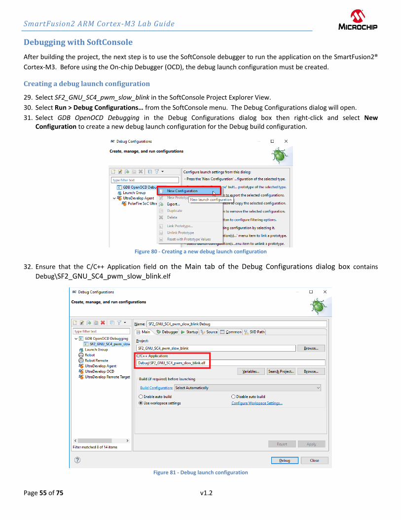
Debugging with SoftConsole
After building the project, the next step is to use the SoftConsole debugger to run the application on the SmartFusion2®
Cortex-M3. Before using the On-chip Debugger (OCD), the debug launch configuration must be created.
Creating a debug launch configuration
29. Select SF2_GNU_SC4_pwm_slow_blink in the SoftConsole Project Explorer View.
30. Select Run > Debug Configurations… from the SoftConsole menu. The Debug Configurations dialog will open.
31. Select GDB OpenOCD Debugging in the Debug Configurations dialog box then right-click and select New Configuration to create a new debug launch configuration for the Debug build configuration.
Figure 80 - Creating a new debug launch configuration
32. Ensure that the C/C++ Application field on the Main tab of the Debug Configurations dialog box contains
Debug\SF2_GNU_SC4_pwm_slow_blink.elf
Figure 81 - Debug launch configuration

SmartFusion2 ARM Cortex-M3 Lab Guide
Page 56 of 75 v1.2
33. Select the Debugger tab of the Debug Configurations dialog box. The Config Options field must contain the correct
command line options/script to be passed to OpenOCD.
34. Enter --command "set DEVICE M2S010" --file board/microsemi-cortex-m3.cfg in the Config Options field.
--command "set DEVICE M2S0XX" specifies the target device, modify based on the target silicon. --file board/microsemi-cortex-m3.cfg is a board script for the integrated Cortex-M3 core of
SmartFusion2®
35. Scroll to the GDB Client Setup field on the Debugger tab. Confirm that the following appear:
• Executable: ${cross_prefix}gdb${cross_suffix}
• Commands: set mem inaccessible-by-default off. If necessary, delete the lines “set arch
riscv:rv32” and “set riscv use_compressed_breakpoints no”
Figure 82 - SoftConsole v6.5 Debugger tab settings for the SmartFusion2® SMF2000 kit

SmartFusion2 ARM Cortex-M3 Lab Guide
Page 57 of 75 v1.2
36. Select the Startup tab and confirm that the default settings are configured as shown in the figure below.
• Disable (un-check) “Pre-run/Restart” under Run/Restart Commands
Figure 83 - Startup tab settings
37. Click Apply to save the changes.
38. Click Debug to launch the Debugger. Click Switch in the Confirm Perspective Switch dialog box. The SoftConsole
Debug perspective will open. The code will be downloaded to the SmartFusion2® SMF2000 board. The program
will be suspended at the first line of main() as shown in the figure below. Use for example F6 key to execute code
single lines (Step Over).

SmartFusion2 ARM Cortex-M3 Lab Guide
Page 58 of 75 v1.2
Figure 84 - SoftConsole Debug perspective
Running the pwm_slow_blink Application
39. Start the Cortex-M3 software application by clicking Run > Resume from the SoftConsole menu. The LEDs will
appear as shown in the table below.
LED State
LED D1 On
LED D2 Blinking (PWM), gradually get dimmer and brighter quickly
LED D3-D9, D10 Off Table 2 – SMF2000 board LED states
40. Suspend the software application by clicking Run > Suspend from the SoftConsole menu or by clicking the Suspend
icon ( ) on the SoftConsole Toolbar.
41. Open the Registers view (Window > Show View > Registers).
42. Select the Registers view on the lower window pane to view the value of the Cortex-M3 internal registers as shown
in the figure below. Your values may differ. If the Registers view is not visible, open it by selecting Window > Show
View > Registers.

SmartFusion2 ARM Cortex-M3 Lab Guide
Page 59 of 75 v1.2
Figure 85 - Cortex-M3 registers
43. Choose Window > Show View > Disassembly to display the assembly level instructions. The Disassembly window
will open on the right side in the middle of the Debug perspective as shown in the figure below.
Figure 86 – SoftConsole Disassembly view
44. Scroll in main.c and locate PWM_PERIOD on line 24.

SmartFusion2 ARM Cortex-M3 Lab Guide
Page 60 of 75 v1.2
Figure 87 - PWM_PERIOD in main.c
45. Changing the value of PWM_PERIOD on line 24 will change the toggle rate of the LED. Try changing the value then
save the file (File > Save). A larger value for the period will make the LED toggle more slowly.
46. Build the project by selecting Project > Build All. Select the Problems View and confirm that there are no errors.
47. Select SF2_GNU_SC4_pwm_slow_blink.elf under the Debug tab in the upper left corner of the SoftConsole Debug
Perspective. Right-click and choose Terminate and Relaunch to stop the debugger and download the new
application.
Figure 88 – Terminating and re-launching the debugger
48. Run the application by clicking Run > Resume from the SoftConsole menu. The LED will toggle at a different rate.

SmartFusion2 ARM Cortex-M3 Lab Guide
Page 61 of 75 v1.2
Driving two LEDs
The application in the sample project only drives one LED, but CorePWM was configured to drive two outputs. Follow
the steps below to modify the application to drive two LEDs.
49. Terminate the software application by clicking Run > Terminate from the SoftConsole menu.
50. Scroll in main to the section with the comment “* Set the initial duty cycle for CorePWM output 1.” on
line 50. This line configures one CorePWM output.
51. Copy the line “PWM_set_duty_cycle( &the_pwm, PWM_1, duty_cycle );”and paste it below the existing line.
Modify the line to drive PWM_2.
52. Scroll to the section with the comment “* Update the duty cycle for CorePWM output 1.” on line 58.
53. Copy the line “PWM_set_duty_cycle( &the_pwm, PWM_1, duty_cycle );”and paste it below the existing line.
Modify the line to drive PWM_2. Save the file after making the edits above.
Figure 89 - Modified code to drive two PWM outputs
54. Repeat the previous steps to build the project. Confirm that there are no errors in the Problems View.
55. Re-launch the debugger (Run > Debug History > SF2_GNU_SC4_pwn_slow_blink Debug).
56. Run the application (Run > Resume) and observe the LEDs. Both LED D2 and LED D3 should toggle at the same rate.
When finished, terminate the application by selecting SF2_GNU_SC4_pwm_slow_blink.elf under the Debug view,
then right-clicking and selecting Terminate and Remove to stop the debugger. Click Yes when prompted about
Terminating.

SmartFusion2 ARM Cortex-M3 Lab Guide
Page 62 of 75 v1.2
Figure 90 – Terminating the application
57. Close the Debug perspective (Window > Perspective > Close Perspective).
58. Close the SF2_GNU_SC4_pwm_slow_blink project by selecting the project name in the Project Explorer then right-
clicking and selecting Close Project.
SmartFusion2 ARM Cortex-M3 Lab Guide
Page 63 of 75 v1.2
Step 8 - Running the RTC_time application (time permitting) In this step, you will open the SF2_GNU_SC4_RTC_time sample project, import the firmware configuration files and run
the application. This sample project uses the SmartFusion2® RTC’s calendar function.
1. Open the SF2_GNU_SC4_RTC_time project by selecting the project name in the Project Explorer then right-clicking
and selecting Open Project.
2. Repeat the steps on pages 46 to 47 to import the firmware drivers and configuration files into the project.
3. Double click main.c in the Project Explorer window to open the file in the SoftConsole C/C++ editor. Scroll through
the file to become familiar with it. The comments at the top of the file describe what the program does.
4. Select SF2_GNU_SC4_RTC_time in the SoftConsole Project Explorer. Build the project by selecting Project > Build All or by clicking the Build All icon.
5. Confirm that no error messages appear in the SoftConsole Problems view.
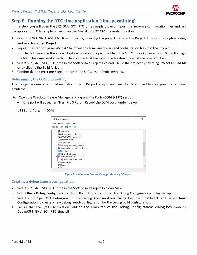
Determining the COM port setting
This design requires a terminal emulator. The COM port assignment must be determined to configure the terminal
emulator.
6. Open the Windows Device Manager and expand the Ports (COM & LPT) section.
• One port will appear as “FlashPro 5 Port”. Record the COM port number below.
USB Serial Port: COM_______
Figure 91 - Windows Device Manager showing COM port
Creating a debug launch configuration
7. Select SF2_GNU_SC4_RTC_time in the SoftConsole Project Explorer View.
8. Select Run > Debug Configurations… from the SoftConsole menu. The Debug Configurations dialog will open.
9. Select GDB OpenOCD Debugging in the Debug Configurations dialog box then right-click and select New Configuration to create a new debug launch configuration for the Debug build configuration.
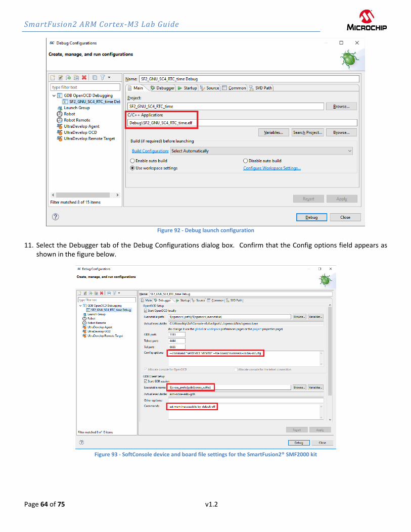
10. Ensure that the C/C++ Application field on the Main tab of the Debug Configurations dialog box contains Debug\SF2_GNU_SC4_RTC_time.elf
SmartFusion2 ARM Cortex-M3 Lab Guide
Page 64 of 75 v1.2
Figure 92 - Debug launch configuration
11. Select the Debugger tab of the Debug Configurations dialog box. Confirm that the Config options field appears as shown in the figure below.
Figure 93 - SoftConsole device and board file settings for the SmartFusion2® SMF2000 kit

SmartFusion2 ARM Cortex-M3 Lab Guide
Page 65 of 75 v1.2
12. Select the Startup tab. Confirm that the settings match the figure below.
Figure 94 - Startup tab settings
13. Click Apply to save if changes were made.

SmartFusion2 ARM Cortex-M3 Lab Guide
Page 66 of 75 v1.2
Launching the Debugger
14. Click Debug in the Create, manage and run configurations dialog box. If you already closed the dialog box, select
Run > Debug from the SoftConsole menu to launch the SoftConsole debugger. You can also launch the debugger by
clicking the debug icon ( ) in the SoftConsole tool bar.
15. Click Switch in the Confirm Perspective Switch dialog box.
Configuring a Serial Terminal View
SoftConsole 6.5 includes a built-in serial terminal view, which eliminates the need to run a separate serial terminal
emulator when connecting to a target board using a UART.
16. Select Window > Show View > Terminal to open a serial terminal. The Terminals view will be visible.
Figure 95 - Terminal view in the Debug perspective
17. Click the Open a Terminal button (highlighted in the figure above) to configure the serial terminal.
18. Enter the following in the Launch Terminal dialog box then click OK:
• Choose terminal: select Serial Terminal from the pull-down menu
• Port: Enter the COM port number recorded on page 63.
• Baud rate: 115200
• Data Bits: 8
• Parity: None
• Stop Bits: 1
• Flow Control: None
• Encoding: Default (ISO-8859-1)
The baud rate, data bits, parity, stop bits and flow control settings are based on the MSS_UART_init function in main().

SmartFusion2 ARM Cortex-M3 Lab Guide
Page 67 of 75 v1.2
Figure 96 - Serial terminal settings - COM port setting will vary
19. Run the software application by clicking the Resume icon ( ) or by clicking Run > Resume from the SoftConsole
menu. The Terminals view will display a message as shown in the figure below.
Figure 97 - SoftConsole Terminals view with message
20. Type d to set the date.
Figure 98 - Changing the date
21. Type t to set the time.

SmartFusion2 ARM Cortex-M3 Lab Guide
Page 68 of 75 v1.2
Figure 99 - Setting the time
22. After becoming familiar with the Debug perspective and the debug features, terminate the debugger by clicking the
Terminate icon ( ) or by selecting Run > Terminate from the SoftConsole menu.
Step 9 - Debugging code running from the SmartFusion2® eNVM The application can also execute from the SmartFusion2® eNVM. The Cortex-M3 has six hardware breakpoints for
debugging from eNVM. This section describes the steps to execute code from the SmartFusion2® eNVM.
Building the project with the Release build configuration
1. Select the SoftConsole C/C++ Perspective by clicking the C/C++ button ( ) or by selecting Window > Perspective
> Open Perspective > C/C++ from the SoftConsole menu.
2. The sample project Release build configuration settings use the debug-in-microsemi-smartfusion2-envm.ld linker
script to build an executable that will run in the SmartFusion2® eNVM.
3. Select SF2_GNU_SC4_RTC_time in the SoftConsole Project Explorer then right-click and select Build Configurations
> Set Active > Release to select the Release configuration as the active build configuration.
4. Build the project build by selecting Project > Build All. Confirm that there are no errors listed in the Problems view.
5. A folder named Release containing the executable for the Release build configuration will be visible in the Project
Explorer.
6. Select SF2_GNU_SC4_RTC_time.map in the Release folder, press right mousebutton and choose “Open With” “Text
Editor” to open the file in the SoftConsole editor. Scroll down to the Memory Configuration section. The section
should appear as shown in the figure below.
SmartFusion2 ARM Cortex-M3 Lab Guide
Page 69 of 75 v1.2
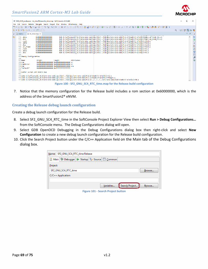
Figure 100 - SF2_GNU_SC4_RTC_time.map for the Release build configuration
7. Notice that the memory configuration for the Release build includes a rom section at 0x60000000, which is the
address of the SmartFusion2® eNVM.
Creating the Release debug launch configuration
Create a debug launch configuration for the Release build.
8. Select SF2_GNU_SC4_RTC_time in the SoftConsole Project Explorer View then select Run > Debug Configurations…
from the SoftConsole menu. The Debug Configurations dialog will open.
9. Select GDB OpenOCD Debugging in the Debug Configurations dialog box then right-click and select New Configuration to create a new debug launch configuration for the Release build configuration.
10. Click the Search Project button under the C/C++ Application field on the Main tab of the Debug Configurations dialog box.
Figure 101 - Search Project button
SmartFusion2 ARM Cortex-M3 Lab Guide
Page 70 of 75 v1.2
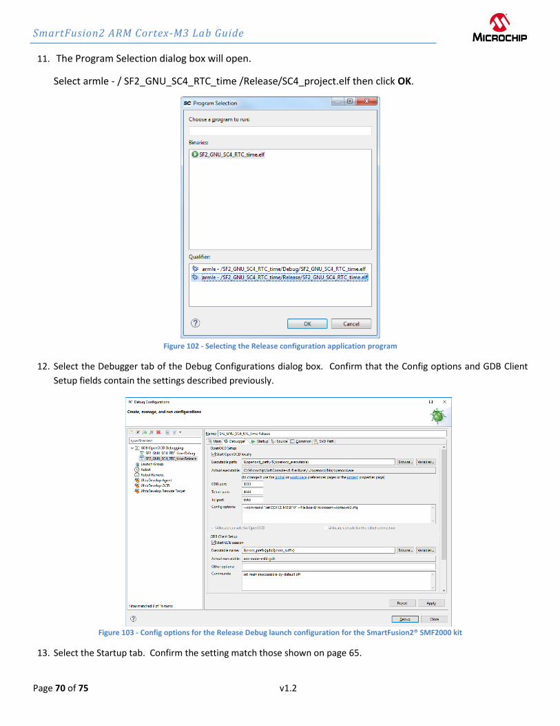
11. The Program Selection dialog box will open.
Select armle - / SF2_GNU_SC4_RTC_time /Release/SC4_project.elf then click OK.
Figure 102 - Selecting the Release configuration application program
12. Select the Debugger tab of the Debug Configurations dialog box. Confirm that the Config options and GDB Client
Setup fields contain the settings described previously.
Figure 103 - Config options for the Release Debug launch configuration for the SmartFusion2® SMF2000 kit
13. Select the Startup tab. Confirm the setting match those shown on page 65.

SmartFusion2 ARM Cortex-M3 Lab Guide
Page 71 of 75 v1.2
14. Click Apply to save the changes.
15. Click Debug to launch the Debugger. Click Switch in the Confirm Perspective Switch dialog box. The SoftConsole
Debug perspective will open and the code will be programmed to the SmartFusion2® eNVM. Messages will appear
in the Console view while the code is being downloaded. When finished the program will be suspended at the first
line of main().
Figure 104 - Console view while downloading to the SmartFusion2® eNVM
16. Select the Terminals view in the Debug Perspective. Right click in the Terminal and select Clear Terminal to remove
any existing text. If necessary, open the Terminals view (Window > Show View > Terminal).
17. Click the Resume icon to run the application. Note that the application runs the same as previously when it was
executing from the SmartFusion2® eSRAM memory.
18. Try setting breakpoints while executing the code. When finished, terminate the debugger and close the Debug
perspective (Window > Close Perspective). Do not close SoftConsole.
19. The C/C++ Perspective will be open. Open the Terminal view (Window > Show View > Terminal) and configure as
described earlier in the document.
20. Reset the SmartFusion2® SMF2000 kit by pressing and releasing SW3.
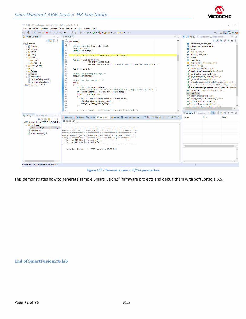
21. Observe the code execution in the Terminals view. The code is running without the debugger because it was
programmed into the SmartFusion2® eNVM.
Note that the serial terminal can be used to display output even when a program is not being debugged - e.g. a
program running from eNVM on power on reset that uses UART output.
SmartFusion2 ARM Cortex-M3 Lab Guide
Page 72 of 75 v1.2
Figure 105 - Terminals view in C/C++ perspective
This demonstrates how to generate sample SmartFusion2® firmware projects and debug them with SoftConsole 6.5.
End of SmartFusion2® lab

SmartFusion2 ARM Cortex-M3 Lab Guide
Page 73 of 75 v1.2
List of Figures Figure 1 - SmartFusion2® Block Diagram ................................................................................................................................ 5
Figure 2 - Libero® SoC Project Manager ................................................................................................................................. 6
Figure 3 - IP Catalog indicating new cores are available ......................................................................................................... 7
Figure 4 - Executing the project creation script ...................................................................................................................... 8
Figure 5 - Script execution report ........................................................................................................................................... 8
Figure 6 - Libero® SoC Design Flow tab ................................................................................................................................... 9
Figure 7 - Entering a name for System Builder ....................................................................................................................... 9
Figure 8 – SmartFusion2® System Builder Device Features page ......................................................................................... 10
Figure 9 - System Builder Device Features after selections .................................................................................................. 11
Figure 10 - System Builder Memories page .......................................................................................................................... 11
Figure 11 - Selecting the hex file for the data storage client ................................................................................................ 12
Figure 12 - Data Storage Client dialog box after importing the hex file ............................................................................... 12
Figure 13 - System Builder Memories page after adding the data storage client ................................................................ 13
Figure 14 - System Builder Peripherals page ........................................................................................................................ 13
Figure 15 - MM_UART_0 configurator .................................................................................................................................. 14
Figure 16 - SmartFusion2® GPIO Configuration .................................................................................................................... 15
Figure 17 - System Builder Peripherals page after adding CorePWM .................................................................................. 16
Figure 18 - corepwm_0 configuration................................................................................................................................... 17
Figure 19 – Configuring the MSS clocks ................................................................................................................................ 18
Figure 20 - System Builder Microcontroller options page .................................................................................................... 19
Figure 21 - System Builder Microcontroller options page after selecting the RTC clock source .......................................... 20
Figure 22 - System Builder SECDED options page ................................................................................................................. 21
Figure 23 - CorePWM TACHINT interrupt ............................................................................................................................. 22
Figure 24 - Fabric memory map ............................................................................................................................................ 23
Figure 25 - Message tab after successfully generating the MSS design ............................................................................... 23
Figure 26 – SF2_MSS_sys_sb_0 component ......................................................................................................................... 24
Figure 27 – Connecting FAB_RESET_N port to VCC .............................................................................................................. 24
Figure 28 – SF2_MSS_sb_0 component after making pin connections ................................................................................ 25
Figure 29– Execute Design Rules Check ................................................................................................................................ 26
Figure 30 - Libero® SoC Message window after generating the design ............................................................................... 26
Figure 31 - Opening the Constraint Editor ............................................................................................................................ 27
Figure 32 - Libero® SoC Enhanced Constraint Manager ....................................................................................................... 27
Figure 33 - Importing the I/O constraint file ......................................................................................................................... 28
Figure 34 - Selecting and saving the I/O constraint file for layout ....................................................................................... 28
Figure 35 - Deriving Timing Constraints ................................................................................................................................ 29
Figure 36 - Message Window ................................................................................................................................................ 29
Figure 37 - Derived Timing Constraints ................................................................................................................................. 29
Figure 38 - Generate Bitstream ............................................................................................................................................. 30
Figure 39 - Successful completion of design implementation .............................................................................................. 31
Figure 40 - Reports tab after implementing the design ........................................................................................................ 32
Figure 41 - Device Manager .................................................................................................................................................. 32
Figure 42 - Run program action ............................................................................................................................................ 33
Figure 43 - Windows Device Manager showing COM port ................................................................................................... 33
SmartFusion2 ARM Cortex-M3 Lab Guide
Page 74 of 75 v1.2
Figure 44 - Configuring Firmware cores for the design ........................................................................................................ 34
Figure 45 - DESIGN FIRMWARE tab ....................................................................................................................................... 34
Figure 46 - Downloading missing firmware cores ................................................................................................................. 35
Figure 47 - Selecting SmartFusion2®_CMSIS version 2.3.105 ............................................................................................... 35
Figure 48 - Generating the CorePWM sample project.......................................................................................................... 35
Figure 49 – CorePWM slow blink sample project options .................................................................................................... 35
Figure 50 - GPIO Simple Blink project files ............................................................................................................................ 36
Figure 51 - Generating the RTC Driver sample project ......................................................................................................... 36
Figure 52 – RTC Time sample project location ...................................................................................................................... 37
Figure 53 - RTC_time project files ......................................................................................................................................... 37
Figure 54 - Exporting the firmware configuration files ......................................................................................................... 38
Figure 55 - Export Firmware options .................................................................................................................................... 38
Figure 56 - Firmware driver location ..................................................................................................................................... 39
Figure 57 - Sample projects on Libero® SoC Files tab ........................................................................................................... 39
Figure 58 – Data Sheet for the design ................................................................................................................................... 40
Figure 59 - SoftConsole 6.5 Workspace Launcher (location shown may differ) ................................................................... 41
Figure 60 - Selecting the SoftConsole workspace ................................................................................................................. 41
Figure 61 – Eclipse Launcher with workspace selected. ....................................................................................................... 42
Figure 62 - SoftConsole v6.5 GUI .......................................................................................................................................... 42
Figure 63 - SoftConsole Import dialog box............................................................................................................................ 43
Figure 64 - Importing the sample projects into the workspace ............................................................................................ 44
Figure 65 - SoftConsole projects in the workspace............................................................................................................... 45
Figure 66 - Importing the firmware configuration files ........................................................................................................ 46
Figure 67 - Importing the firmware configuration files into the project .............................................................................. 47
Figure 68 - Question dialog box ............................................................................................................................................ 47
Figure 69 - SF2_GNU_SC4_pwm_slow_blink after importing the firmware configuration files .......................................... 48
Figure 70 - main.c in the SoftConsole editor ........................................................................................................................ 48
Figure 71 - platform.h in the SoftConsole editor .................................................................................................................. 49
Figure 72 - Project Properties dialog .................................................................................................................................... 50
Figure 73 - Selecting all build configurations ........................................................................................................................ 50
Figure 74 - Project Include paths .......................................................................................................................................... 51
Figure 75 - Confirming the Cross ARM C Compiler Other compiler flags setting ................................................................. 52
Figure 76 - Debug configuration linker script ....................................................................................................................... 53
Figure 77 - Release configuration linker script ..................................................................................................................... 53
Figure 78 - Selecting the build configuration ........................................................................................................................ 54
Figure 79 - Problems view after building the project ........................................................................................................... 54
Figure 80 - Creating a new debug launch configuration ....................................................................................................... 55
Figure 81 - Debug launch configuration ................................................................................................................................ 55
Figure 82 - SoftConsole v6.5 Debugger tab settings for the SmartFusion2® SMF2000 kit ................................................... 56
Figure 83 - Startup tab settings ............................................................................................................................................. 57
Figure 84 - SoftConsole Debug perspective .......................................................................................................................... 58
Figure 85 - Cortex-M3 registers ............................................................................................................................................ 59
Figure 86 – SoftConsole Disassembly view ........................................................................................................................... 59
Figure 87 - PWM_PERIOD in main.c ...................................................................................................................................... 60
SmartFusion2 ARM Cortex-M3 Lab Guide
Page 75 of 75 v1.2
Figure 88 – Terminating and re-launching the debugger ..................................................................................................... 60
Figure 89 - Modified code to drive two PWM outputs ......................................................................................................... 61
Figure 90 – Terminating the application ............................................................................................................................... 62
Figure 91 - Windows Device Manager showing COM port ................................................................................................... 63
Figure 92 - Debug launch configuration ................................................................................................................................ 64
Figure 93 - SoftConsole device and board file settings for the SmartFusion2® SMF2000 kit ............................................... 64
Figure 94 - Startup tab settings ............................................................................................................................................. 65
Figure 95 - Terminal view in the Debug perspective ............................................................................................................ 66
Figure 96 - Serial terminal settings - COM port setting will vary .......................................................................................... 67
Figure 97 - SoftConsole Terminals view with message ......................................................................................................... 67
Figure 98 - Changing the date ............................................................................................................................................... 67
Figure 99 - Setting the time .................................................................................................................................................. 68
Figure 100 - SF2_GNU_SC4_RTC_time.map for the Release build configuration ................................................................ 69
Figure 101 - Search Project button ....................................................................................................................................... 69
Figure 102 - Selecting the Release configuration application program ................................................................................ 70
Figure 103 - Config options for the Release Debug launch configuration for the SmartFusion2® SMF2000 kit .................. 70
Figure 104 - Console view while downloading to the SmartFusion2® eNVM....................................................................... 71
Figure 105 - Terminals view in C/C++ perspective ................................................................................................................ 72