dhanalakshmi college of engineering...
TRANSCRIPT

DHANALAKSHMI COLLEGE OF ENGINEERING Tambaram, Chennai –601 301
DEPARTMENT OF CIVIL ENGINEERING
CE 8311- CONSTRUCTION MATERIALS LABORATORY
III SEMESTER - R 2017
Name :
Register No. :
Class :
LABORATORY MANUAL

2 Format No.:DCE/Stud/LP/34/Issue : 00/Revision : 00
MISSION
DHANALAKSHMI COLLEGE OF ENGINEERING
Dhanalakshmi College of Engineering is committed to provide highly disciplined, conscientious and
enterprising professionals conforming to global standards through value based quality education and
training.
To provide competent technical manpower capable of meeting requirements of the industry
To contribute to the promotion of academic excellence in pursuit of technical education at different
levels
To train the students to sell his brawn and brain to the highest bidder but to never put a price tag
on heart and soul
DEPARTMENT OF CIVIL ENGINEERING
The department of civil engineering is committed to the relentless pursuit of innovation in training
budding engineers to compete globally in the field of civil engineering and to establish a unique identity for
the development of high quality human and knowledge resource in diverse areas of technology and
management.
The department of civil engineering strives to provide strong theoretical foundation complemented
with extensive practical training
To inculcate value-based, socially committed professionalism to the cause of overall development
of student and society.
MISSION
VISION
VISION

3 Format No.:DCE/Stud/LP/34/Issue : 00/Revision : 00
PROGRAMME EDUCATIONAL OBJECTIVES (PEOs)
1. Fundamentals
To provide students with a solid foundation in Mathematics, Science and fundamentals of
engineering, enabling them to apply, to find solutions for engineering problems and use this
knowledge to acquire higher education
2. Core Competence
To train the students in Civil Engineering technologies so that they apply their knowledge and
training to compare, and to analyze various engineering industrial problems to find solutions
3. Breadth
To provide relevant training and experience to bridge the gap between theories and practice this
enables them to find solutions for the real time problems in industry, and to design products
4. Professionalism
To inculcate professional and effective communication skills, leadership qualities and team spirit in
the students to make them multi-faceted personalities and develop their ability to relate engineering
issues to broader social context
5. Lifelong Learning/Ethics
To demonstrate and practice ethical and professional responsibilities in the industry and society in
the large, through commitment and lifelong learning needed for successful professional career

4 Format No.:DCE/Stud/LP/34/Issue : 00/Revision : 00
PROGRAMME OUTCOMES (POs)
a) To demonstrate and apply knowledge of Mathematics, Science and engineering fundamentals in
Civil Engineering field
b) To design a component, a system or a process to meet the specific needs within the realistic
constraints such as economics, environment, ethics, health, safety and manufacturability
c) To demonstrate the competency to use software tools for computation, simulation and testing of
Civil engineering structures
d) To identify, formulate and solve Civil engineering problems
e) To demonstrate an ability to visualize and work on laboratory and multi-disciplinary tasks
f) To function as a member or a leader in multidisciplinary activities
g) To communicate in verbal and written form with fellow engineers and society at large
h) To understand the impact of Civil Engineering in the society and demonstrate awareness of
contemporary issues and commitment to give solutions exhibiting social responsibility.
i) To demonstrate professional & ethical responsibilities
j) To exhibit confidence in self-education and ability for lifelong learning
k) To participate and succeed in competitive exams

5 Format No.:DCE/Stud/LP/34/Issue : 00/Revision : 00
CE8311– CONSTRUCTION MATERIALS LABORATORY
1. To learn the principles and procedures of testing Concrete and Highway materials and to get hands on
experience by conducting the tests and evolving inferences.
List of Experiments I. Test on Fine Aggregates
1. Grading of fine aggregates
2. Test for specific gravity and test for bulk density
3. Compacted and loose bulk density of fine aggregate
II. Test on Coarse Aggregate
1. Determination of impact value of coarse aggregate
2. Determination of elongation index
3. Determination of flakiness index
4. Determination of aggregate crushing value of coarse aggregate
III. Test on concrete
1. Test for Slump
2. Test for Compaction factor
3. Test for Compressive strength - Cube & Cylinder
4. Test for Flexural strength
IV. Test on Bricks and Blocks
1. Test for compressive strength of bricks and blocks
2. Test for Water absorption of bricks and blocks
3. Determination of Efflorescence of bricks
4. Test on tiles
1. The students will have the required knowledge in the area of testing of construction materials and components of construction elements experimentally.
.
COURSE OUTCOMES

6 Format No.:DCE/Stud/LP/34/Issue : 00/Revision : 00
CONTENTS
Sl.No. LIST OF EXPERIMENT Page No.
CYCLE 1 – EXPERIMENTS
1. Grading of fine aggregates
2. Test for specific gravity and test for bulk density
3. Compacted and loose bulk density of fine aggregate
4. Determination of impact value of coarse aggregate
5. Determination of elongation index
6. Determination of flakiness index
CYCLE 2 – EXPERIMENTS
7 Determination of aggregate crushing value of coarse aggregate
8 Test for Slump
9 Test for Compaction factor
10 Test for Compressive strength - Cube & Cylinder
11 Test for Flexural strength
12 Test for compressive strength of bricks and blocks
13 Test for Water absorption of bricks and blocks
14 Determination of Efflorescence of bricks
15 Test on tiles

7 Format No.:DCE/Stud/LP/34/Issue : 00/Revision : 00
Expt. No.01 DETERMINATION OF FINENESS MODULUS OF FINE AGGREGATE
Aim:
To determine fineness modulus of fine aggregate and classifications based on IS: 383- 1970.
Apparatus Required:
1. Test Sieves conforming to IS: 460-1962.
2. Specification of 4.75 mm, 2.36 mm, 1.18 mm, 600 micron, 300micron, 150 micron.
3. Weigh Balance
4. Gauging Trowel
5. Stop Watch
Procedure:
1. The sample shall be brought to an air-dry condition before weighing and sieving.
2. The air-dry sample shall be weighed and sieved successively on the appropriate sieves starting with the
largest.
3. Material shall not be forced through the sieve by hand pressure.
4. Lumps of fine material, if present, may be broken by gentle pressure with fingers against the side of the
sieve.
5. Light brushing with a fine camel hair brush may be used on the 150-micron and 75-micron IS Sieves to
prevent aggregation of powder and blinding of apertures.
6. On completion of sieving, the material retained on each sieve, together with any material cleaned from the
mesh, shall be weighed.

8 Format No.:DCE/Stud/LP/34/Issue : 00/Revision : 00
Observation and Calculation
Weight of empty tray = kg Weight of tray + fine aggregate = kg Weight of fine aggregate = kg
I S Sieve Weight Retained on Sieve
Percentage of Weight Retained (%)
Percentage of Weight Passing (%)
Cumulative Percentage of Passing (%)
4.75 mm
2.36 mm
1.18 mm
600 micron
300 micron
Total
Fineness modulus = F/100
Result:
The fineness modulus of fine aggregate is _.
Outcome:
At the end of the experiment, student acquires knowledge in the determination of the fineness
modulus of given aggregate.

9 Format No.:DCE/Stud/LP/34/Issue : 00/Revision : 00
1. Fine Aggregates should pass through which IS sieve?
2. How many types of fine aggregates are there based on source?
3. What is the fineness modulus value of fine sand?
4. Which of the materials can be used as fine aggregates?
5. What is the specific gravity for sand?
6. In the ratio 1:4:8, which number indicates quantity of fine aggregates?
7. Which size coarse aggregate is ideal for use in concrete mix?
8. Which of the following sand type is excellent for use in mortar and concrete work?
9. What is sand composed of?
10. Which IS code gives the grading of sand?
1. To calculate the fineness of sand which is used in the construction fields.
2. Used for calculation of Mix design of concrete for construction.
Viva - voce
Applications

10 Format No.:DCE/Stud/LP/34/Issue : 00/Revision : 00
Expt. No.02 DETERMINATION OF SPECIFIC GRAVITYOF FINE AGGREGATE
Aim:
To determine specific gravity of fine aggregate
Apparatus Required: 1. Pycnometer (either a Pycnometer jar with conical top or a stoppered bottle having a capacity of at least
50ml)
2. 4.75mm sieve
3. Weighing balance
4. Oven
5. Glass rod
6. Distilled water
Theory:
Specific gravity G is defined as the ratio of the weight of an equal volume of soil solids at a given temperature
to the weight of an equal volume of distilled water at that temperature, both weights being taken in air. The
Indian Standard specifies 27oC as the standard temperature for reporting the specific gravity.
Procedure:
1. Clean and dry the Pycnometer
2. Weigh the empty Pycnometer with its cap (W1)
3. Take about 200gmof oven dried soil passing through 4.75mm sieve into the Pycnometer and weigh
again (W2)
4. Add sufficient de-aired water to cover the soil and screw on the cap
5. Shake the Pycnometer well and remove entrapped air if any
6. Fill the Pycnometer with water completely
7. Dry the Pycnometer from outside and weigh it (W3)
8. Clean the Pycnometer by washing thoroughly
9. Fill the cleaned Pycnometer completely with water up to its top with cap screw on
10. Weigh the Pycnometer after drying it on the outside thoroughly (W4)
11. Repeat the procedure for three samples and obtain the average value of specific gravity.

11 Format No.:DCE/Stud/LP/34/Issue : 00/Revision : 00
Observation and Calculation
Calculate the specific gravity of the soil, as follows,
Specific gravity = GS = (W2- W1)
(W4- W1)(W3- W2)
Where,
Weight of empty Pyconometer, W1 = Weight of Pyconometer + soil sample, W2 = Weight of Pyconometer + soil sample + water, W3 = Weight of Pyconometer + water, W4 =
Result:
The specific gravity of the test sample =
Outcome:
Gained knowledge related to various properties of soil (Specific gravity).

12 Format No.:DCE/Stud/LP/34/Issue : 00/Revision : 00
1. What is soil mechanics?
2. What are main types of soils?
3. What is empirical correlation between PSD and permeability?
4. What is meant by degree of saturation?
5. What are the principles of direct shear test?
6. What is the effect of pore pressure on shear strength of soil?
7. How will you find the shear strength of cohesion less soil?
8. What are the types of shear tests based on drainage?
9. What is meant by shear strength and failure envelope?
10. What are the shear strength parameters?
11. What is cohesion and stress path?
12. What is angle of internal friction?
13. What are the various methods of determination of shear strength in the laboratory?
14. What is the differential equation of deflection of a bent beam?
15. What are the disadvantages of direct shear test?
16. What are the types of tri-axial test based on drainage conditions?
17. What is meant by plastic index, saturated mass density?
18. Distinguish between relative density, relative compaction.
1. To calculate the weight properties of soil like void ratio, degree of saturation and density properties.
2. Used for calculation of Mix design of concrete for construction.
Viva - voce
Application
s

13 Format No.:DCE/Stud/LP/34/Issue : 00/Revision : 00
Expt. No.03 DETERMINATION OF COMPACTED AND LOOSE BULK DENSITY OF FINE AGGREGATE
Aim:
To determine compacted and loose bulk density of fine aggregate

14 Format No.:DCE/Stud/LP/34/Issue : 00/Revision : 00
Apparatus Required:
1. Weighing balance
2. Cylindrical metal measure
3. Tamping rod
Procedure for Compacted Bulk Density
1. Measure the volume of the cylindrical metal measure by pouring water into the metal measure and record the volume “V” in litre.
2. Fill the cylindrical metal measure about one-third full with thoroughly mixed aggregate and tamp it 25 times using tamping bar.
3. Add another layer of one-third volume of aggregate in the metal measure and give another 25 strokes of tamping bar.
4. Finally fill aggregate in the metal measure to over-flowing and tamp it 25 times.
5. Remove the surplus aggregate using the tamping rod as a straightedge.
6. Determine the weight of the aggregate in the measure and record that weight “W” in kg.
Procedure for Loose Bulk Density
1. Measure the volume of the cylindrical metal measure by pouring water into the metal measure and
record the volume “V” in litre.
2. Fill the cylindrical measure to overflowing by means of a shovel or scoop, the aggregate being
discharged from a height not exceeding 5 cm above the top of the measure
3. Level the top surface of the aggregate in the metal measure, with a straightedge or tamping bar.
4. Determine the weight of the aggregate in the measure and record the weight “W” in kg.

15 Format No.:DCE/Stud/LP/34/Issue : 00/Revision : 00
Observation and Calculation
Calculation for Compacted Bulk Density
Compacted unit weight or bulk density = W/V
Where,
W = Weight of compacted aggregate in cylindrical metal measure, kg
V = Volume of cylindrical metal measure, litre
Calculation For Loose Bulk Density
Loose unit weight or bulk density = W/V
Where,
W = Weight of loose aggregate in cylindrical metal measure, kg
V = Volume of cylindrical metal measure, litre
Result:
The compacted bulk density of the given sample =
The compacted bulk density of the given sample =
Outcome:
Gained knowledge related to various properties of soil (Bulk density).

16 Format No.:DCE/Stud/LP/34/Issue : 00/Revision : 00
1. What is unconsolidated undrained condition?
2. What is consolidated undrained condition?
3. What is the main cause of slope failure?
4. What are the factors affecting permeability tests?
5. What is meant by effective stress?
6. What is meant by angle of repose of soil?
7. Explain coulomb’s law.
8. What are the merits and demerits of direct shear test?
9. What are the different types of failure of a triaxcal compression test specimen?
10. What do you mean by stress‐path?
11. What is peak shear strength? West out the factors it depends on?
12. What is Rohr’s circle? What are the characteristics of Rohr’s circle?
13. What are the type of triaxial test?
14. What are the advantages of triaxial test?
15. What is compaction of the soil?
16. What is the Relationship between the Dry Density - Water Content?
17. What is meant by voids line?
18. How to differentiate finite slope and infinite slope?
19. How do u explain factor of safety of an infinite slope in case of cohesion less soil?
1. It is used to find out the densities of soils at various field condition.
2. It is also used for determining moisture content of soil.
Viva - voce
Applications

17 Format No.:DCE/Stud/LP/34/Issue : 00/Revision : 00
Expt. No.04 DETERMINATION OF IMPACT VALUE OF
COARSE AGGREGATE
Aim:
To determine the aggregate impact value of given aggregate
Apparatus Required:
1. Impact testing machine: The machine consists of a metal base. A detachable cylindrical steel cup of
internal diameter 10.2 cm and depth 5 cm. A metal hammer of weight between 13.5 to 14 kg, 10 cm in
diameter and 5 cm long. An arrangement for raising the hammer and allow it to fall freely between
vertical guides from a height of 38 cm on the test sample in the cup
2. A cylindrical metal measure having 7.5 cm and depth of 5 cm for measuring aggregates
3. A tamping rod of circular cross section, 1 cm in diameter and 23 cm long, rounded at one end
4. IS sieve of sizes 12.5 mm, 10 mm and 2.36 mm
5. Balance of capacity not less than 500 gm to weigh accurate up to 0.01 gm
Procedure:
1. The test sample consists of aggregates passing 12.5 mm sieve and retained on 10 mm sieve and dried
in an oven for 4 hours at a temperature of 1000 C to 1100C
2. The aggregates are filled up to about 1/3 full in the cylindrical measure and tamped 25 times with
rounded end of the tamping rod
3. The rest of the cylindrical measure is filled by two layers and each layer being tamped 25 times
4. The overflow of aggregates in cylindrically measure is cut off by tamping rod using its straight edge
5. Then the entire aggregate sample in a measuring cylinder is weighted nearing to 0.01 gm
6. The aggregates from the cylindrical measure are carefully transferred into the cup which is firmly fixed in
position on the base plate of machine. Then it is tamped 25 times
7. The hammer is raised until its lower face is 38 cm above the upper surface of aggregates in the cup and
allowed to fall freely on the aggregates. The test sample is subjected to a total of 15 such blows each
being delivered at an interval of not less than one second. The crushed aggregate is then removed from
the cup and the whole of it is sieved on 2.36mm sieve until no significant amount passes.
The fraction passing the sieve is weighed accurate to 0.1 gm
8. Repeat the above steps with other fresh sample
9. Let the original weight of the oven dry sample be w1 gm and the weight of fraction passing 2.36 mm IS
sieve be w2 gm. Then aggregate impact value is expressed as the % of fines formed in terms of the total

18 Format No.:DCE/Stud/LP/34/Issue : 00/Revision : 00
weight of the sample.
Observation and Calculation
Sl.No. Details of Sample Trail 1 Trail 2 Average
1 Total Weight of aggregate sample filling the cylinder measure = W1 g
2 Weight of aggregate passing 2.36mm sieve after the test = W2 g
3 Weight of aggregate retained 2.36mm sieve after the test = W3 g
4 (W1 -W2 +W3 )
5 Aggregate Impact Value = (W2 / W1) * 100 Percent
Result:
The mean aggregate impact value is _%.
Outcome:
At the end of the experiment, student acquires knowledge in the determination of the aggregate
impact value of given aggregate.

19 Format No.:DCE/Stud/LP/34/Issue : 00/Revision : 00
1. What is impact load?
2. What are materials used for impact test?
3. What is aggregate?
4. What are the tests conducted for aggregate?
5. What is abrasion?
6. What is sieve analysis?
7. What is attrition?
8. What is the different size of sieve available for aggregate test?
9. What is specific gravity?
10. What is void ratio?
.
1. The purpose of an impact test is to determine the ability of the material to absorb energy during a
collision.
2. This energy may be used to determine the toughness, impact strength, fracture resistance, impact
resistance or fracture resistance of the material depending on the test that was performed and the
characteristic that is to be determined.
3. These values are important for the selection of materials that will be used in applications that require the
material to undergo very rapid loading processes such as in vehicular collisions.
Viva–voce
Application

20 Format No.:DCE/Stud/LP/34/Issue : 00/Revision : 00
Expt. No. 05 SHAPE TEST (ELONGATION INDEX)
Aim:
To determine the Elongation index of the given aggregate sample
Apparatus Required:
1. Length gauge
2. IS sieve
Procedure:
1. The sample is sieved through IS Sieve specified in the table. A minimum of 200 aggregate pieces of
each fraction is taken and weighed
2. Each fraction is thus gauged individually for length in a length gauge. The gauge length is used should
be those specified in the table for the appropriate material
3. The pieces of aggregate from each fraction tested which could not pass through the specified gauge
length with its long side are elongated particles and they are collected separately to find the total weight
of aggregate retained on the length gauge from each fraction
4. The total amount of elongated material retained by the length gauge is weighed to an accuracy of at
least 0.1% of the weight of the test sample
5. The weight of each fraction of aggregate passing and retained on specified sieves sizes are found –
W1, W2, W3, …………… and the total weight of sample determined =W1+ W2+W3+……………..= W
gm. Also the weights of the material from each fraction retained on the specified gauge length are
found = x1, x2, x3…… and the total weight retained determined = x1+x2+x3+……..= X gm
6. The elongation index is the total weight of the material retained on the various length gauges,
expressed as a percentage of the total weight of the sample gauged
(x1 + x2 + x3 + …)
Elongation index = ----------------------------- x 100
(W1 + W2 + W3 + …)

21 Format No.:DCE/Stud/LP/34/Issue : 00/Revision : 00
Observation and Calculation
Size of aggregate
Length gauge
Weight of the fraction consisting
of atleast 200 pieces in gm
Weight of aggregates in each fraction
retained on length gauge gm
Passing through IS sieve mm
Retained on IS sieve mm
63 50 -
50 40 81
40 25 58.50
31.5 25 -
25 20 40.5
20 16 32.4
16 12.5 25.6
12.5 10 20.2
10 6.3 14.7
Result:
The elongation index of a given sample of aggregate is %
Outcome:
At the end of the experiment, student acquires knowledge in the determination of elongation
index of the given aggregate sample.

22 Format No.:DCE/Stud/LP/34/Issue : 00/Revision : 00
1. What is Elongation index
2. What are the types of stones used for coarse aggregate?
3. What do you understand by the term repeatability and reproducibility?
4. What are all the size of sieves used
5. Explain the term viscosity.
6. What are the uses of coarse aggregate in concrete
7. What are the precautions to be taken during viscosity test using orifice viscometer?
8. What is the significance of flow value in Marshall Test?
9. What is filler?
This test is used to determine the particle shape of the aggregate and each particle
shape being preferred under specific conditions.
Viva - voce
Applications

23 Format No.:DCE/Stud/LP/34/Issue : 00/Revision : 00
Expt. No. 06 SHAPE TEST (FLAKINESS INDEX)
Aim:
To determine the flakiness index of the given aggregate sample
Apparatus Required:
1. The apparatus consist of a standard thickness gauge
2. IS Sieve of size 63, 50, 40, 31.5, 25, 20, 16, 12.5, 10 and 6.3
3. Balance to weight the samples
Procedure:
1. The sample is sieved with the sieves mentioned in the table
2. A minimum of 200 pieces of each fraction to be tested are taken and weighed (W1 gm)
3. In order to separate flaky materials, each fraction is then gauged for thickness on thickness gauge, or
in bulk on sieve having elongated slots as specified in the table
4. Then the amount of flaky materials passing the gauge is weighed to an accuracy of atleast 0.1% of test
sample
5. Let the weight of the flaky materials passing the gauge be W1gm. Similarly the weights of the fractions
passing and retained on the specified sieves be W1, W2, W3, etc, are weighed and the total weight
W1+W2+W3+… = W gm is found. Also the weights of the materials passing each of the specified
thickness gauge are found =W1, W2, W3…. And the total weight of the material passing the different
thickness gauges = W1+W2+W3… = W gm is found
6. Then the flakiness index is the total weight of the flaky material passing the various thickness gauges
expressed as a percentage of the total weight of the sample gauged
(w1 + w2 + w3 + ……)
Flakiness index = ----------------------------- x 100
(W1 + W2 + W3 + …)

24 Format No.:DCE/Stud/LP/34/Issue : 00/Revision : 00
Size of aggregate Thickness gauge
(0.6 times the mean sieve) mm
Weight of the fraction consisting
of atleast 200 pieces in gm
Weight of aggregates in each fraction passing on
thickness gauge gm
Passing through
IS sieve mm
Retained on IS
sieve mm
63 50 33.90
50 40 27.00
40 25 19.50
31.5 25 16.50
25 20 13.50
20 16 10.80
16 12.5 8.55
12.5 10 6.75
10 6.3 4.89
Result:
The flakiness index of a given sample of aggregate is %
Outcome:
At the end of the experiment, student acquires knowledge in the determination of the
flakiness index of the given aggregate sample.

25 Format No.:DCE/Stud/LP/34/Issue : 00/Revision : 00
1. Define – Flash and fire points
2. What is the significance of flash and fire point test?
3. What are the parameters that affect the result of flash and fire point tests?
4. Define – Specific gravity
5. What is the use of finding specific gravity?
6. What are the factors affecting specific gravity test?
7. What are the applications of penetration test?
8. What are the precautions to be taken while conducting a penetration test?
9. What are the factors which affect the ring and ball test results?
10. What is softening point?
This test is used to determine the particle shape of the aggregate and each particle shape being
preferred under specific conditions.
Viva - voce
Applications

26 Format No.:DCE/Stud/LP/34/Issue : 00/Revision : 00
Expt. No. 07 DETERMINATION OF AGGREGATE
CRUSHING VALUE OF COARSE AGGREGATE
Aim:
To determine crushing value of course aggregate
Apparatus required:
1. A 15-cm diameter open-ended steel cylinder, with plunger and base-plate, of the general form
and dimensions.
2. Straight metal tamping rod.
3. A balance of capacity 3 Kg.
4. IS Sieves of sizes 12.5, 10 and 2.36 mm.
5. Cylindrical metal measure of sufficient rigidity to retain its form under rough usage and of the
following internal dimensions: Diameter 11.5 cm and Height 18.0 cm.
Procedure:
1. The material for the standard test shall consist of aggregate passing a 12.5 mm IS Sieve and
retained on a 10 mm IS Sieve, and shall be thoroughly separated on these sieves before testing.
2. The aggregate shall be tested in a surface-dry condition. If dried by heating, the period of drying
shall not exceed four hours, the temperature shall be 100 to 110°C and th aggregate shall be
cooled to room temperature before testing.
3. The appropriate quantity may be found conveniently by filling the cylindrical measure in three
layers of approximately equal depth, each layer being tamped 25 times with the rounded end of
the tamping rod and finally leveled off, using the tamping rod as a straight-edge.
4. The weight of material comprising the test sample shall be determined (Weight A) and the same
weight of sample shall be taken for the repeat test.
5. The apparatus, with the test sample and plunger in position, shall then be placed between the
platens of the testing machine and loaded at as uniform a rate as possible so that the total load
is reached in 10 minutes. The total load shall be 400 kN.
6. The load shall be released and the whole of the material removed from the cylinder and sieved
on a 2.36 mm IS Sieve for the standard test. The fraction passing the sieve shall be weighed
(Weight B).

27 Format No.:DCE/Stud/LP/34/Issue : 00/Revision : 00
Observation and Calculation:
Aggregate Crushing Value = (B/A)x100
A weight (gm.) of saturated surface - dry sample,
B weight (gm.) of fraction passing through appropriate sieves
Result:
The aggregate crushing value of given sample of coarse aggregate is ……….. % .
Outcome:
The students will be able to determine the crushing value of coarse aggregate.

28 Format No.:DCE/Stud/LP/34/Issue : 00/Revision : 00
1. Modulus of elasticity, E is calculated by which formula?
2. What is the dia of steel rod?
3. What is the dia of the cylinder used for the test?
4. What is the aggregate crushing value?
5. What are the sieves used in the test?
6. What are the parameters that affect the result of this test?
7. Modulus of rupture is calculated by using which formula?
8. Coarse aggregates are classified into how many groups?
9. Graded aggregate contains particles of size.
10. Elongation index of coarse aggregates is calculated by which method?
This test is used to determine the aggregate value. The low aggregate crushing value is the
strong one. The value should not be more the 45% for concrete.
Viva - voce
Applications

29 Format No.:DCE/Stud/LP/34/Issue : 00/Revision : 00
Expt. No. 08 DETERMINATION OF SLUMP VALUE OF
CONCRETE (SLUMP TEST)
Aim:
To determine the workability of the cement concrete by Slump test
Apparatus required:
1. Ingredients for the cement concrete
2. Slump mould (Shape of the frustum)
3. Tamping rod
4. Trowel
5. Non-porous base plate
Procedure:
1. Initially weigh the following material to prepare the cement concrete for testing.
(i) 2 kg of cement (ii) 4 kg of sand (iii) 8kg of Aggregate
2. Add water 50% by weight of cement (1000 ml) and mix them thoroughly on a platform.
3. The slump mould is cleaned for any remaining cement particles or impurities and is properly oiled at
the inner surface.
4. Then the prepared concrete sample is put into the mould, which is placed on a non-porous plate in 3
layers with a tapping of 25 times for each layer by a standard tamping rod.
5. The extra heap of concrete present on the top of the mould is cut off or leveled off.
6. Remove the mould from the concrete immediately by raising it slowly and carefully in the vertical
direction.
7. Allow the concrete to subside
8. Measure the difference in level between the height of the mould and that of the highest point of the
subsided concrete in mm. This is the slump value of the concrete.
9. Repeat the test for W/C ratios of 0.55, 0.60 and 0.65. Calculation: The ratio of the weight of fines formed to the total sample weight in each test shall be expressed as a percentage.
30 Format No.:DCE/Stud/LP/34/Issue : 00/Revision : 00
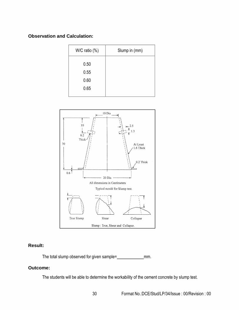
Observation and Calculation:
W/C ratio (%) Slump in (mm)
0.50
0.55
0.60
0.65
Result:
The total slump observed for given sample= mm.
Outcome:
The students will be able to determine the workability of the cement concrete by slump test.

31 Format No.:DCE/Stud/LP/34/Issue : 00/Revision : 00
1. What is meant by workability?
2. What are the different types of slump?
3. What is the use of aggregates in concrete?
4. What is meant by PCC and RCC?
5. What are the different types of concrete?
6. What is use of cement in concrete?
7. What are the different grades of cement
8. What is meant by water cement ratio?
9. What is the accepted range of slump values in different structures?
10. What are the different sizes of coarse aggregate?
Slump test is used to determine the workability of fresh concrete. Slump test as per IS: 1199 –
1959 is followed. The apparatus used for doing slump test are Slump cone and tamping rod.
Viva–voce
Applications

32 Format No.:DCE/Stud/LP/34/Issue : 00/Revision : 00
Expt. No.09 DETERMINATION OF COMPACTION FACTOR OF
CONCRETE
Aim:
To determine the workability of cement concrete by compaction factor test
Apparatus Required:
1. Ingredients of cement concrete
2. Compaction factor apparatus
3. Tamping rod
4. Trowel
5. Measuring jar
6. Weighing balance
Procedure:
1. Initially weigh the following materials to prepare the cement concrete for testing.
a) 2 kg of cement, 4 kg of sand and 8 kg of coarse aggregate
b) Add water at the rate of 50% by weight of cement (1000 ml) to it and mix them thoroughly on a
platform.
2. The compaction factor apparatus is cleaned and the cylinder is properly oiled.
3. The sample freshly prepared is put into the top hopper with the shutter closed.
4. The clamp is released and the shutter is opened and thus the sample falls into the second hopper
whose shutter is closed.
5. The shutter of the second hopper is also opened to allow the concrete sample into the cylinder.
6. The cylinder is weighed and the weight of the partially compacted concrete is found by deducting the
weight of the cylinder.
7. The density of the partially compacted concrete mix is calculated by knowing the volume of the
cylinder.
8. The same sample is filled into the cylinder in 3 layers and each layer is compacted for 25 blows by
using a standard tamping rod.
9. The weight of the fully compacted sample is found out as in the above case.

33 Format No.:DCE/Stud/LP/34/Issue : 00/Revision : 00
10. The compaction factor for the given sample of cement concrete is found out by using the formula,
Weight of partially compacted concrete Compaction factor =
Weight of fully compacted concrete
11. Repeat the test for W/C ratios of 0.55, 0.60 and 0.65.
Observation and Calculation:
SL.NO.
Water
Cement
Ratio
Mass with
Partially
Compacted
Concrete
(W2)
Mass with
Fully
Compacted
Concrete
(W3)
Mass with
Partially
Compacted
Concrete
(W2-W1)
Mass with
Fully
Compacted
Concrete
(W3-W1)
(W2-W1)
C.F =
(W3-W1)
1
2
3
0.50
0.55
0.60

34 Format No.:DCE/Stud/LP/34/Issue : 00/Revision : 00
Result:
The Compaction factor of the given sample of concrete is %.
Outcome:
At the end of the experiment, student acquires knowledge in the determination of workability of the
workability of cement concrete by compaction factor test.

35 Format No.:DCE/Stud/LP/34/Issue : 00/Revision : 00
1. What are the factors affecting the choice of the method of test on concrete?
2. Differentiate between fully compacted and partially compacted concrete.
3. What is the significance of compacted concrete?
4. What are the factor affecting the workability of concrete
5. How does strength correlate with other properties of hardened concrete?
6. What are the requirements for curing the specimens?
7. Why compaction is essential?
8. How compaction of concrete can be achieved?
9. What is the significance of moment of inertia with respect to bending stress?
10. What is the advantage of vibrating?
Compaction factor test is used to determine the workability of fresh concrete.
Viva–voce
Application

36 Format No.:DCE/Stud/LP/34/Issue : 00/Revision : 00
Expt. No.10 DETERMINATION OF COMPRESSIVE STRENGTH
OF CONCRETE CUBE AND CYLINDER
Aim:
To determine the compressive strength of the hardened concrete by testing concrete cube and
Cylinder
Apparatus Required:
1. Compressive testing machine of capacity 100 T
2. Measuring scale
3. Cube mould of 150 mm x 150 mm size
4. Tamping rod
5. Water bath
Formula:
For Cube and Cylinder Ultimate load N/ mm2
Ultimate Compressive Strength = Area of Cross section
Procedure:
A. Preparation of Specimen:
1. The mould is assembled, cleaned and the oil is applied.
2. Required quantity of ingredients and water are taken and thoroughly mixed.
3. The prepared concrete is filled in 5 cm layers and compacted in a vibrator.
4. The specimen is kept for 24 hours in the mould and then removed from the mould and immersed in
water.
B. Testing of Specimen:
1. The specimen is taken out after particular days of curing
2. Measure the dimensions of the concrete cube
3. Place the concrete cube in the compression testing machine
4. Apply the load to the specimen uniformly
5. Apply further load until the specimen fails. Note down the load at failure
6. This load is the ultimate compressive load
7. Repeat the procedure for remaining specimens

37 Format No.:DCE/Stud/LP/34/Issue : 00/Revision : 00
Observations:
Specimen Trails Mean Value
N/mm2 1 2 3
Load on
cubes, kN
Calculation:
For Cube and Cylinder:
Ultimate Compressive Strength =
Ultimate load
Area of Cross section
= N/ mm2
Result:
Ultimate compressive strength of concrete cube ( days) = N/ mm2
Outcome:
At the end of the experiment, student acquires knowledge in the determination of hardened
concrete by testing concrete cube and cylinder.

38 Format No.:DCE/Stud/LP/34/Issue : 00/Revision : 00
1. What is construction joint?
2. What is the size of test specimens?
3. What is the size of aggregates used test specimens?
4. What is the purpose of compression test?
5. List out the different size of moulds.
6. What is meant by bleeding?
7. What are the limitations of compression test?
8. What is the purpose of compression test?
9. What is honey comb in concrete?
10. What is the purpose of compression test?
Compressive strength of concrete cube is used to many factors such as water-cement ratio,
cement strength, quality of concrete material, quality control during production of concrete.
Viva–voce
Application

39 Format No.:DCE/Stud/LP/34/Issue : 00/Revision : 00
Expt. No. 11 TEST FOR FLEXURAL STRENGTH
Aim:
To determine the modulus of rupture of concrete
Apparatus Required:
1. Beam mould
2. Flexure beam attachment and
3. Universal Testing Machine
Procedure:
1. Prepare the test specimens in the standard manner [size of the specimen in cm (15 x 15 x 70 ) ]
2. Store test specimens in water at a temperature of 24˚C to 30˚C for 48 hours before testing (Specimens
must be in wet condition during testing)
3. Place the specimen in the machine in such a manner that the load is applied to the upper most surface
as cast in the mould along two lines spaced 20 cm apart
4. Align axis of the specimen carefully with the axis of the loading device
5. Apply load without shock and increase continuously at a rate of 0.4 t/min and it is increased until the
sample fails
6. Note down the maximum load applied
7. Measure the distance between the line of fracture and nearest support
Observation:
Size of the mould =
Breadth of the specimen (b) =
Depth of the specimen (D) =
Load at failure (P) =
Distance between the lines of fracture =
and the nearer support (a) =
Length of the span, (l) =

40 Format No.:DCE/Stud/LP/34/Issue : 00/Revision : 00
Calculation:
If a > 20 cm then
Modulus of rupture fb =
If a < 20 cm
P x l
b x d2
Modulus of rupture fb =
3P x a
b x d2
If a < 17
Discard the specimen
Test Requirements of Concrete:
Modulus of rupture should not be less than value given below:
S.No
Grade of Concrete Modulus of rupture
At 72 ± 2 hours N/mm2 At 7 days N/mm2
1 M10 1.2 1.7
2 M15 1.5 2.1
3 M20 1.7 2.4
4 M25 1.9 2.7
5 M30 2.1 3.0
6 M35 2.3 3.2
7 M40 2.5 3.4
Result:
Modulus of rupture for the given concrete beam = .
Outcome:
At the end of the experiment, student acquires knowledge in the determination of the modulus
of rupture of concrete.

41 Format No.:DCE/Stud/LP/34/Issue : 00/Revision : 00
1. What is meant by UTM?
2. What are the failures in concrete?
3. What is flexure?
4. What is mean by shear?
5. Differentiate shear and flexure.
6. What are the different types of shear failure?
7. What is modulus of rupture?
8. What is young’s modulus?
9. What is bulk modulus?
10. Where does the flexure failure occur in structure?
This test method is used for determining the flexural strength of concrete by the use of a simple
beam with center-point loading.
Viva–voce
Application

42 Format No.:DCE/Stud/LP/34/Issue : 00/Revision : 00
Expt. No.12 TEST FOR COMPRESSIVE STRENGTH OF BRICKS AND BLOCKS
Aim:
To determine the compressive strength of the bricks and blocks.
Apparatus Required:
1. Compressive testing machine of capacity 100 T
2. Measuring scale
3. Tamping rod
4. Water bath
5. Trowel
Formula:
Ultimate load N/ mm2
Ultimate Compressive Strength = Area of Cross section
Procedure:
1. Eight bricks are taken for the compressive strength testing.
2. The bricks are then immersed in water at room temperature for 24 hours.
3. Then these are taken out of water and surplus water on the surfaces is wiped off with a moist cloth.
4. The frog of the bricks is flushed level with cement mortar (1:3)
5. The bricks are stored under damp jute bags for 24 hours followed by its immersion in water at room temperature for three days.
6. The bricks are placed in the compression testing machine with flat faces horizontal and mortar filled face being upwards.
7. Load is applied at a uniform rate of 14 N/ m2 per minute till failure.

43 Format No.:DCE/Stud/LP/34/Issue : 00/Revision : 00
Observations:
Sl No
Load at Failure (N)
Average area of back
faces (mm2)
Compressive
Strength. (N/mm2) Remarks
1
2
3
4
5
6
7
8
Calculation:
Ultimate Compressive Strength =
Ultimate load
Area of Cross section
= N/ mm2
Result:
Ultimate compressive strength of Brick block = N/ mm2
Outcome:
At the end of the experiment, student acquires knowledge in the determination of strength of
the brick blocks.

44 Format No.:DCE/Stud/LP/34/Issue : 00/Revision : 00
1. What is the recommended size of brick?
2. A good brick should not absorb more than what percent of water when soaked?
3. Which of bricks is not preferred for construction?
4. The compressive strength of the brick should be.
5. A good brick when dropped from height of 1 meter can:
6. What should be observed when brick is broken?
7. Unburnt bricks are also called.
8. Burnt bricks can be further classified into how many types?
9. First class bricks are used for:
10. The minimum crushing strength of third class brick?
Since the clay bricks or burnt bricks are strong, hard, durable, resistive to abrasion and fire, therefore, they are
used as a structural material in different structures.
Application
Viva–voce

45 Format No.:DCE/Stud/LP/34/Issue : 00/Revision : 00
Expt. No.13 TEST FOR WATER ABSORPTION OF BRICKS AND BLOCKS
Aim:
To determine the water absorption of the bricks and blocks.
Apparatus Required:
1. A sensitive balance capable of weighing within 0.1% of the mass of the specimen
2. Ventilated oven.
Procedure:
1. Dry the specimen in a ventilated oven at a temperature of 105 °C to 115°C till it attains substantially constant mass.
2. Cool the specimen to room temperature and obtain its weight (M1) specimen too warm to touch shall not be used for this purpose.
3. Immerse completely dried specimen in clean water at a temperature of 27+2°C for 24 hours.
4. Remove the specimen and wipe out any traces of water with damp cloth and weigh the specimen after it has been removed from water (M2).

46 Format No.:DCE/Stud/LP/34/Issue : 00/Revision : 00
Calculation:
Water absorption, % by mass, after 24 hours immersion in cold water in given by the formula,
Result:
Water absorption of the given bricks = …………. %
Outcome:
At the end of the experiment, student acquires knowledge in the determination of water
absorption capacity of the brick blocks.

47 Format No.:DCE/Stud/LP/34/Issue : 00/Revision : 00
1. In absorption test on brick, how many hours it has to be soaked in cold water?
2. What is the loading rate used in compressive strength test?
3. How is hardness of brick tested?
4. What is the maximum permissible tolerance for length and width respectively?
5. What should be observed ideally when two bricks are struck together?
6. Creep test is carried out in accordance with which code book?
7. Unburnt bricks are also called.
8. Burnt bricks can be further classified into how many types?
9. First class bricks are used for:
10. The minimum crushing strength of third class brick ?
Since the clay bricks or burnt bricks are strong, hard, durable, resistive to abrasion and fire, therefore, they are used as a structural material in different structures
Application
Viva–voce

48 Format No.:DCE/Stud/LP/34/Issue : 00/Revision : 00
Expt. No.14 DETERMINATION OF EFFLORESCENCE OF BRICKS
Aim:
To determine the efflorescence of the bricks.
Apparatus Required:
1. A shallow flat bottom dish containing sufficient distilled water to completely saturate the specimens. The dish shall be made of glass, porcelain or glazed stoneware and of size 180 mm x 15O mm X 40 mm depth for square shaped and 200 mm diameter X 40 mm depth for cylindrical shaped.
2. Distilled water
3. Brick specimens Procedure:
1. Fill distilled water in shallow dish and place one end of brick in dish. Water should fill in dish such that
bricks should immersed in water up to 25 mm depth.
2. Place this whole arrangement in a warm ventilated room such that whole water is absorbed by the
specimen and the surplus water will get evaporated.
3. Cover the dish containing brick with suitable glass cylinder so that there will not excessive evaporation
from dish.
4. When whole water get absorbed and brick appears to be dry, place a similar quantity of water in the dish
and allow it to evaporate as before.
5. After this process examine the bricks for efflorescence and report results.

49 Format No.:DCE/Stud/LP/34/Issue : 00/Revision : 00
Result:
Results of efflorescence test shall be reported as nil, slight, moderate, heavy or serious.
1. Nil- If there is no noticeable deposit of efflorescence.
2. Slight- when less than 10% of exposed area of brick is covered by a thin layer of salt.
3. Moderate- When there is a heavier deposit than under ‘slight’ and covering up to 50 percent of
the exposed area of the brick surface but unaccompanied by powdering or flaking of the surface.
4. Heavy – When there is a heavy deposit of salts covering 50 percent or more of the exposed area
of the brick surface but unaccompanied by powdering or flaking of the surface.
5. Serious-when there is heavy deposit of salt acquired by powdering and/or flaking of exposed
surface.
Outcome:
At the end of the experiment, student acquires knowledge in the efflorescence pattern of brick
blocks.

50 Format No.:DCE/Stud/LP/34/Issue : 00/Revision : 00
1. End of a brick is placed in glass dish containing water and it is tested for efflorescence after it is absorbed or evaporated.
2. When observed efflorescence is more than 10% but less than 50% of exposed area, it is?
3. How is structure of brick tested?
4. What does M1 indicate in the formula:
5. % water absorption = M2 – M1 ⁄M2 x 100
6. Unburnt bricks are also called?
7. Which of the following is not a feature of second class bricks?
8. Pilas are under burnt bricks.is it true or false?
9. Which of the following bricks types use least amount of clay?
10. Which of the following type of bricks is made for jambs of doors and windows?
11. Which of the following type of bricks is made for jambs of doors and windows? True or false?
Since the clay bricks or burnt bricks are strong, hard, durable, resistive to abrasion and fire, therefore, they are used as a structural material in different structures
Application
Viva–voce

51 Format No.:DCE/Stud/LP/34/Issue : 00/Revision : 00
Expt. No.15 TEST ON TILES
Aim:
To determine the water absorption and bulk density of tiles.
Apparatus Required:
1. Oven – capable of maintaining temp of about 1100c
2. Balance – accurate to 0.01% of the mass of test specimen
3. Water bath
4. Desiccators
5. Chamois leather
6. Wire basket
Preparation of Sample
1. A test sample consists of 10 numbers of whole tiles. If the surface area of individual tile specimen is
greater than 0.04m2, then the numbers of tile specimens in a sample can be reduced to 5.
2. When the mass of each individual tile is below 50 g, then take sufficient number of tiles, so that each test
specimen weighs 50g to 100g.
3. If the dimension of tile is longer than 200 mm, then it may be cut up, but include the cut pieces in the
measurement.
Test Procedure
1. Dry the tiles in the oven at 110±50C, until it attains constant mass, i.e. when the difference between two
successive weighing at intervals of 24 h is less than 0.1%.
2. Cool the tiles in the desiccators over silica gel, until cooled to room temperature.
3. Weigh each tile specimen and record the weight of individual test specimen (i.e. m1) in the observation
sheet.
4. Place the tiles vertically, with no contact between them, in water in the water bath so that there is a depth
of 50 mm water above and below the tiles. Maintain the water level 50 mm above the tiles throughout the
test.
5. Heat the water until boiling and continue to boil for 2 h. After 2 h, switch off the source of heat and allow
the tiles to cool, still completely immersed in this water, overnight.

52 Format No.:DCE/Stud/LP/34/Issue : 00/Revision : 00
6. Remove the tiles from the water bath and remove the surface water from the tiles pieces by chamois
leather.
7. Immediately weigh each tile and record the weight (i.e. m2) in the observation sheet.
8. Now place the specimens in the wire basket that is immersed in water and determine the weight of each
specimen to the nearest 0.01g.
Calculation
1. Water Absorption
For each tile, calculate the water absorption in percentage (to the first decimal place) of the dry mass using the following formula.
Water absorption (%) = [(m2 – m1) / m1] * 100
Where,
m1 = mass of the dry tile, in g
m2 = mass of the wet tile, in g
Calculate the average water absorption of the sample as the average of the individual result.
2. Bulk Density
Bulk density (B), in g/cm3, of a specimen is the ratio of its dry mass divided by the exterior volume, including pores. Calculate bulk density of tile as follow.
B = m1 / V
Where,
B = bulk density of tile, g/cm3
m1 = mass of dry tile, g
V = exterior volume, in cm3: = (m2 – m3)
m3 = mass of suspended tile impregnated by boiling water method, in g
Calculate the average bulk density of the sample as the average of the individual result.

53 Format No.:DCE/Stud/LP/34/Issue : 00/Revision : 00
Result:
Water absorption of the given tiles = …………. % Bulk density of the given sample =
Outcome:
At the end of the experiment, student acquires knowledge in the determination of water
absorption capacity of the tiles.

54 Format No.:DCE/Stud/LP/34/Issue : 00/Revision : 00
1. Quarry tile is also called?
2. Which tile is the most versatile?
3. Which is used for skirting around bathtubs and mosaics?
4. Why drain tiles are suitable for laying in waterlogged areas?
5. Which type of tile is suitable for air-conditioned rooms, gymnasiums and skating rinks?
6. How many layers is the encaustic tile made up of?
7. How many Manglore tiles are required to cover 1 square meter of roof?
8. Which IS code gives classifications of ceramic tile?
9. How many operations are involved in the manufacturing of tiles?
10. What type of clay is selected for tile manufacture?
11. At what point is a glaze applied to a tile?
12. What is the meaning of slip?
Tiles are mostly used for the flooring purposes and decoration purposes depending upon the
field we use and can be easily handled and economic.
Viva – voce
Application