dhanalakshmi srinivasan engineering college antenna and wave propagation.pdfwhen the current changes...
TRANSCRIPT
QB/AWP/FORMAT-01 DSEC/DEPT. OF ECE
AWP 1 DSEC/ECE/ QB/III YR/ AWP
DHANALAKSHMI SRINIVASAN ENGINEERING COLLEGEPERAMBALUR-621212
DEPARTMENT OF ELECTRONICS AND COMMUNICATION ENGINEERING
EC 6602 –ANTENNA AND WAVE PROPAGATION
YEAR : III SEMESTER : VIUNIT I FUNDAMENTALS OF RADIATION
PART-A (2 MARKS)
1. Define gain. (April/may-2011,Nov/Dec-2011)The ratio of maximum radiation intensity in given direction to the maximum radiation intensity from a
reference antenna produced in the same direction with same input power. Gain is usually measured in dB.
Gain (G) =
2. Define radiation pattern.Radiation pattern is the relative distribution of radiated power as a function of distance in space.It is a
graph which shows the variation in actual field strength of the EM wave at all points which are at equal distance from the antenna. The energy radiated in a particular direction by an antenna is measured in terms of FIELD STRENGTH.(E Volts/m).
3. Define Directivity. (April/may-2011,May/June-2012)The directivity (D) of an antenna is the ratio of the maximum radiation intensity U (θ,φ)max to its
average radiation intensity U (θ,φ)avg.
Directivity from Pattern : D = ( , )( , ) ; Directivity from beam area : D = Ω
4. Define effective aperture of an antenna. ( Nov/Dec-2011 May/June-2012)It is the area over which the power is extracted from the incident wave and delivered to the load is
called effective aperture (Ae). Effective aperture Ae =
= m2
5. Write the importance of radiation resistance of an antenna. (April/may -2008,April/may-2011, May/June-2016)
Radiation resistance is that part of an antenna's feed point resistance that is caused by the radiation of electromagnetic waves from the antenna, as opposed to loss resistance (also called ohmic resistance) which generally causes the antenna to heat up. It is also defined as the equivalent resistance that used to dissipate the same amount of power as is radiated by the antenna.
6. Explain the parameter of an antenna: Bandwidth.Bandwidth is the band of frequencies between the higher frequency (fH) and lower frequency (fL)
over which a signal is transmitted.
For Narrow band antenna: BW = fH – fL ; For Wide band antenna: BW =
7. Define Half Power Beam Width. (Nov/Dec-2012)Antenna beam width is a measure of directivity of an antenna. Antenna beam width is an angular
width in degrees, measured on the radiation pattern (major lobe) between points where the radiated power has fallen to half its maximum value. Half Power Beam Width (HPBW) is Beam width between half power points.
8. Define antenna temperature.Antenna Temperature (TA) is a parameter that describes how much noise an antenna produces in a
given environment. This temperature is not the physical temperature of the antenna. Antenna temperature is also sometimes referred to as Antenna Noise Temperature.
9. Define antenna input impedance.The input impedance ZA of a transmitting antenna is the ratio of the voltage to current at the terminals
of the antenna.

QB/AWP/FORMAT-01 DSEC/DEPT. OF ECE
AWP 2 DSEC/ECE/ QB/III YR/ AWP
ZA=RA+jXA ; RA= input resistance, XA= input reactanceRA= Rr + RL ; Rr= radiation resistance, RL=loss resistance
10. What are θ & φ patterns in antenna radiation pattern? ( Nov/Dec 2013) The two types of radiation patterns are Field pattern & Power pattern.
The θ component of the electric field as a function of the angles θ and φ or Eθ (θ, φ)(V m−1). The φ component of the electric field as a function of the angles θ and φ or Eφ(θ, φ)(V m−1). The phases of these fields as a function of the angles θ and φ or δθ (θ, φ) and δφ(θ, φ) (rad or deg).
11. Define Radiation intensity. (May/June-2007 ,Nov/Dec 2013)
The power radiated from an antenna per unit solid angle is called the radiation intensity U (watts per steradian or per square degree). The radiation intensity is independent of distance.
12. Compare short dipole from half wave dipole. ( May/June-2014)S.
No.Parameters Half wave dipole Short dipole
1. Antenna LengthAntenna length is equal to a
half-wavelength at the frequency (λ/2)
Antenna length is equal to (λ/10)
2. Radiation ResistanceRrad=80π2(l/ λ)2=73Ω
Since l= λ/2Rrad=80π2(dl/ λ)2=7.9 Ω
Since dl= λ/10
3. Directivity (When θ= π/2) D=1.642 D=1.5
13. What is a folded dipole? (May/Jun- 2011)A folded dipole antenna is an antenna with two parallel dipoles of radius ‘a’ and length ‘L’ at the ends
to form a narrow loop.
Impedance Zfd = Where, Zt = Input impedance of transmission line, Zd = Input impedance of dipole.
PART-B (16MARKS)
1. Derive the expression for the field quantities radiated from a λ/2 dipole and prove the radiation resistance to be 73Ω. (May/june2016(16))
λ/2 dipole or half wave dipole or half wavelength is the fundamental antenna of metal rod or tubing or
thin wire which has a physical length of half wave length in free space at the frequency of operation. It is also called as half wave doublet.
`Fig.1: λ/2 Dipole Or Half Wave Dipole

QB/AWP/FORMAT-01 DSEC/DEPT. OF ECE
AWP 3 DSEC/ECE/ QB/III YR/ AWP
Vector potential, =
Radiated Field quantities, =
A/m
| | = V/m ; since = =120
Total radiated power, = 60 . = 73.14 ; Since I=1.219
Radiation resistance, = =73 Ω ; where = 73.142. Derive the expression for the field quantities (E and H) for a small oscillation current element.
(May/june2016(16))An infinitesimal element excited with an alternating current is called the Hertzian dipole. It is very
short length of wire over which the current distribution can be assumed uniform. A short dipole is initially in neutral condition and the moment a current starts to flow in one direction, one half of the dipole require an excess of charge and the other a deficit because a current is a flow of electrical charge. Then ,there will be a voltage between the two halves of the dipole. When the current changes its direction this charge unbalance will cause oscillations. Hence an oscillating current will result in an oscillating voltage. Since, in such dipole, electric charge oscillates, it may be called as Oscillating electric dipole.
Fig.2: Hertzian dipole
Instantaneous current, =Retarded current, [ ] =Far field component,
E = + E = + + E = 0 H = 0 H = 0 H = +

QB/AWP/FORMAT-01 DSEC/DEPT. OF ECE
AWP 4 DSEC/ECE/ QB/III YR/ AWP
3. (i) Define the following parameters and their dependence an antenna performance (1) Radiation pattern. (2) Input Impedance (3) Polarization. ( May/june2014(16) , May/june2015(8)) (1) Radiation pattern: (May/june2012(6))
Radiation pattern is the relative distribution of radiated power as a function of distance in space. It is a graph which shows the variation in actual field strength of the EM wave at all points which are at equal distance from the antenna. The energy radiated in a particular direction by an antenna is measured in terms of FIELD STRENGTH.(E Volts/m).(2) Input Impedance:
The input impedance ZA of a transmitting antenna is the ratio of the voltage to current at the terminalsof the antenna.
ZA=RA+jXA ; RA= input resistance, XA= input reactanceRA= Rr + RL ; Rr= radiation resistance, RL=loss resistance
(3) Polarization: (May/june2012(5)The polarization of the radio wave can be defined by direction in which the electric vector E is aligned
during the passage of at least one full cycle. Also polarization can also be defined the physical orientation of the radiated electromagnetic waves in space. The polarizations are three types. They are Elliptical polarization, circular polarization and linear polarization.
(ii) Derive the Magnetic Field Components of a Dipole having the dimension l<<λ/2. ( May/june2014(16)) Dipole having the dimension l<<λ/2 is a Hertzian dipole antenna. Magnetic Field Components ofthis Dipole is, H = 0H = 0
H = I Lsinθ4 + 1
4. (i) Explain the terms : (1) Beam Solid Angle (App/May2008(5), App/May2011(5)) (2) Antenna Temperature (May/june2012(5))
(3) Reciprocity of antenna. (May/June-2013(6) ( May/june2014(16)) (8)
(1) Beam Solid Angle The beam area or beam solid angle or of an antenna is given by the normalized power pattern over
a sphere.= ∫ ∫ ( , ) (Sr) ; Where, d = sin d d
(2) Antenna Temperature (TA) :TA is a parameter that describes how much noise an antenna produces in a given environment. This
temperature is not the physical temperature of the antenna. Antenna temperature is also sometimes referred to as Antenna Noise Temperature.(3)Reciprocity of an antenna.
If an e.m.f is applied to the terminals of an antenna no.1 and the current measured at the terminals of the another antenna no.2, then an equal current both in amplitude and phase will be obtained at the terminal of the antenna no.1 if the same e.m.f is applied to the terminals of antenna no.2. (ii) Derive the current and vector potential of a Hertzian dipole. ( May/june2014(16))
Current of a Hertzian dipole
Instantaneous current, = Retarded current, [ ] =
QB/AWP/FORMAT-01 DSEC/DEPT. OF ECE
AWP 5 DSEC/ECE/ QB/III YR/ AWP
Vector potential of a Hertzian dipole
Initially, = ∫ [ ]// dz Finally, =
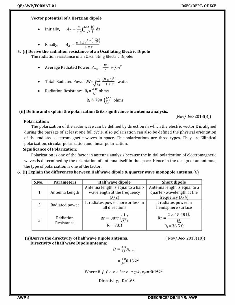
5. (i) Derive the radiation resistance of an Oscillating Electric Dipole The radiation resistance of an Oscillating Electric Dipole:
Average Radiated Power, Pavg = /
Total Radiated Power ,W= ( ) watts
Radiation Resistance, Rr = ohms
Rr 790 ohms
(ii) Define and explain the polarization & its significance in antenna analysis.
(Nov/Dec-2013(8)) Polarization:
The polarization of the radio wave can be defined by direction in which the electric vector E is aligned during the passage of at least one full cycle. Also polarization can also be defined the physical orientation of the radiated electromagnetic waves in space. The polarizations are three types. They are Elliptical polarization, circular polarization and linear polarization.
Significance of Polarization:Polarization is one of the factor in antenna analysis because the initial polarization of electromagnetic
waves is determined by the orientation of antenna itself in the space. Hence in the design of an antenna,the type of polarization is one of the factor.
6. (i) Explain the differences between Half wave dipole & quarter wave monopole antenna.(6)
S.No. Parameters Half wave dipole Short dipole
1 Antenna LengthAntenna length is equal to a half-
wavelength at the frequency (λ/2)
Antenna length is equal to a quarter-wavelength at the
frequency (λ/4)
2 Radiated powerIt radiates power more or less in
all directionsIt radiates power in hemisphere surface
3 Radiation Resistance
Rr = 80π lλRr = 73Ω
Rr = 2 × 18.28II
Rr = 36.5 Ω
(ii)Derive the directivity of half wave Dipole antenna. ( Nov/Dec- 2013(10)) Directivity of half wave Dipole antenna: =
= .0.13
Where , = 0.13Directivity, D=1.63
QB/AWP/FORMAT-01 DSEC/DEPT. OF ECE
AWP 6 DSEC/ECE/ QB/III YR/ AWP
7. (i) State and prove Lorentz Reciprocity Theorem for antennas. (8) Lorentz Reciprocity Theorem:
If an e.m.f is applied to the terminals of an antenna no.1 and the current measured at the terminals of the another antenna no.2, then an equal current both in amplitude and phase will be obtained at the terminal of the antenna no.1 if the same emf is applied to the terminals of antenna no.2.
According to reciprocity theorem,I1= I2 Provided E12=E21 ; E12=E21 Provided I1= I
(ii)Define: (1) Gain (2) Directivity (3)Antenna Temperature (4) Antenna input impedance (Nov/Dec-2012(16) ,Nov/Dec- 2013(8)) (1) Gain
Gain of an antenna is defined as the ratio of maximum radiation intensity in a given direction to the maximum radiation intensity of a reference antenna.
Power gain is defined as the ratio of maximum power radiated by a test antenna to the maximum power radiated by a reference antenna.
(2) DirectivityIt indicates the effectiveness of concentrating power into a limited solid angle. It is the ratio between maximum radiation intensity to the average radiation intensity.
Directivity D = 4π/A Where, A = Beam solid angle(3)Antenna Temperature
TA is a parameter that describes how much noise an antenna produces in a given environment. This temperature is not the physical temperature of the antenna. Antenna temperature is also sometimes referred to as Antenna Noise Temperature.(4) Antenna input impedance
The input impedance ZA of a transmitting antenna is the ratio of the voltage to current at the terminals of the antenna.
ZA=RA+jXA ; RA= input resistance, XA= input reactance RA= Rr + RL ; Rr= radiation resistance, RL=loss resistance
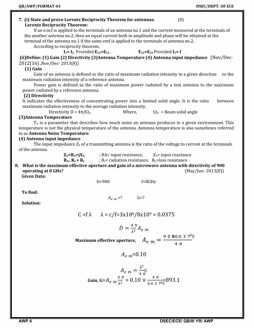
8. What is the maximum effective aperture and gain of a microwave antenna with directivity of 900operating at 8 GHz? (May/Jun- 2013(8))
Given Data: D=900 f=8GHz
To find:
=? G=? Solution:
C =f λ λ = c/f=3x108/8x109 = 0.0375
= Maximum effective aperture, = × .
=0.10
= G
Gain, G= = 0.10 × . =893.1

QB/AWP/FORMAT-01 DSEC/DEPT. OF ECE
AWP 7 DSEC/ECE/ QB/III YR/ AWP
9. A join dipole of /2 long.? If it has loss resistance of 2 , calculate : (i) Directivity (ii) Gain (iii) Effective Aperture (iv) Beam Solid Angle and (v) Radiation Resistance (May/Jun- 2013(16))
Given Data: = /2 Rl =2 To find: =? G = ? Rr = ? ΩA=? Solution:
Formulas: ΩA= G=KD Rr =73 Ω = k=
= ; V=Eλ/π ; S=EH=E 2 / ;
= ( / )× × . ) = = 20.62
= = ×20.62 = . ΩA= = . = ΩA =4.86
G=KD we know that, K=1 G= .10. Obtain the expression for radiated power of half-wave dipole antenna. (Nov/Dec-2007(16) Nov/Dec 2012(16))
Half wave dipole or half wavelength is the fundamental antenna of metal rod or tubing or thin wire which has a physical length of half wave length in free space at the frequency of operation. It is also called as half wave doublet.
Total radiated power, = 60 .
Where, I= ∫ ( )
= 73.14 ; Since I=1.219

QB/AWP/FORMAT-01 DSEC/DEPT. OF ECE
AWP 8 DSEC/ECE/ QB/III YR/ AWP
UNIT II - APERTURE AND SLOT ANTENNAS
PART-A (2 MARKS)
1. What are the features of pyramidal horn antenna? (April/May2011)A pyramidal horn is formed by flaring both the E plane and H plane of a rectangular waveguide. The
features are,(i) Pyramidal microwave horn antenna, with a bandwidth of 0.8 to 18 GHz. (ii) A coaxial cable feed line attaches to the connector visible at top. (iii) This type is called a ridged horn.(iv) The curving fins visible inside the mouth of the horn increase the antenna's bandwidth
2. What is the basic concept of reflector antenna?An antenna reflector is a device that reflects electromagnetic waves. Antenna reflectors can exist as a
standalone device for redirecting radio frequency (RF) energy, or can be integrated as part of an antennaassembly.
3. Compare flat reflector and corner reflector. ? (Nov/Dec-2011) Flat reflector antenna:
It has a large flat sheet near a linear dipole antenna. It reduces backward radiation. It provides sustainable gain in the forward direction by reducing the spacing between the antenna
and the sheet. Corner reflector antenna:
It is a retro reflector consisting of two or three mutually perpendicular, intersecting flat surfaces which reflects electromagnetic waves back towards the source.
The intersecting surfaces often have square shapes. It consists of a balanced half wave dipole placed in front of a conducting surface which has been
bent at an angle of 90 degree or less. 4. What are the merits and applications of offset feed reflector antenna? (May/June-2013)
The aperture blocking defect can be avoided by using an offset feed reflector which is applicable to focal feed in cassegrain feed.
The applications are,(i) Fixed point to point microwave communication (ii) Satellite reception and tracking
5. What are the applications of micro strip antenna? (Nov/Dec-2011)The applications of micro strip antennas are
(i) Satellite radio receivers.(ii) Broad Band Communications (wireless).(iii) Air craft’s.
6. What are the features of micro strip antenna? (May/June-2012)A Micro strip Antenna in its simplest form consists of a radiating patch on one side of Dielectric sub-
strate and a ground plane on the other side. Most common shapes are rectangular and circular. However, other Shapes such as the square, mendered, triangular, semicircular and annular ring Shapes are also used.
Advantages of Micro strip Antennas like Light weight, inexpensive and robust, easy to Fabricate & Easy to feed.
7. Mention the types of feeding structures used for micro strip patch antennas. (May/June-2013)The four most popular feed techniques used: Micro Strip Line, Coaxial Probe (Both Contacting Schemes), Aperture Coupling And

QB/AWP/FORMAT-01 DSEC/DEPT. OF ECE
AWP 9 DSEC/ECE/ QB/III YR/ AWP
Proximity Coupling (Both Non-Contacting Schemes).8. Why antenna measurements are usually done in Fraunhofer zone? (AU MJ 2016) (May/June-2016)
Because in this region, the radiation pattern does not change shape with distance (although the fields still die off as 1/R, the power density dies off as 1/R^2). Also, this region is dominated by radiated fields, with the E- and H-fields orthogonal to each other and the direction of propagation as with plane waves.
9. State Hyugen’s principle. (April/May-2011, Nov/Dec-2012, May/Jun- 2015) -3Huygen’s principle states that each point on a primary wave front can be considered to be a new
source of a secondary spherical wave that a secondary wave front can be constructed as the envelope of these secondary waves.
10. State field equivalence principle (May/Jun-2014)Field equivalence principle (Huygens principle) states that each point on a primary Wave front can be
considered to be a new source of a secondary spherical wave and that a secondary wave front can be constructed as the envelope these secondary waves.
11. What do you meant by pyramidal horn? (May/Jun-2011)In horn antenna, if flaring is done along both the walls ( E & H), E-plane and H-plane, then it is called as
a pyramidal horn.12. What is Slot Antenna? Which antenna is complementary to the slot dipole? (May/Jun-2011)
The slot antenna is an opening cut in a sheet of a conductor, which is energized through a coaxial cable or wave guide. The dipole antenna is the complementary to the slot antenna. The metal and air regions of the slot areinterchanged for the dipole.
13. What are secondary antennas? And Explain with examples. (Nov/Dec-2017)
Antennas that are not radiators by themselves are called as secondary antennas.
The examples are Cassegrain, Hyperbolic antennas. Cassegrain antenna is a parabolic antenna in which
the feed antenna is mounted at or behind the surface of the concave main parabolic reflector dish and is
aimed at a smaller convex secondary reflector suspended in front of the primary reflector. The beam of
radio waves from the feed illuminates the secondary reflector, which reflects it back to the main reflector
dish, which reflects it forward again to form the desired beam
14. On what principle slot antenna works? Explain the principle. (May/June-2016)This slot behaves according to Babinet's principle as resonant radiator. This principle relates the
radiated fields and impedance of an aperture or slot antenna to that of the field of a dipole antenna. The polarization of a slot antenna is linear. The fields of the slot antenna are almost the same as the dipole antenna, but the field’s components are interchanged: a vertical slot has got an horizontal electric field; and the vertical dipole has got a vertical electrical field.
15. What are the various feeds used in reflector antenna? ? (Nov/Dec-2011)The various feeds used in reflector antenna are
(i) Dipole antenna (ii) Horn feed (iii) End fire feed (iv) Cassegrain feedPART-B (16MARKS)
1. Discuss the geometry of a parabolic reflector and the significance of f/D ratio. Explain its feed configuration. (May/jun2011(16),May/Jun-2016(16))
A parabolic antenna is an antenna that uses a parabolic reflector, a curved surface with the cross-sectional shape of a parabola, to direct the radio waves. The most common form is shaped like a dish and is popularly called a dish antenna or parabolic dish. The main advantage of a parabolic antenna is that it has high directivity. It functions similarly to a searchlight or flashlight reflector to direct the radio waves in a

QB/AWP/FORMAT-01 DSEC/DEPT. OF ECE
AWP 10 DSEC/ECE/ QB/III YR/ AWP
narrow beam, or receive radio waves from one particular direction only. Parabolic antennas have some of the highest gains, meaning that they can produce the narrowest beam widths, of any antenna type.
Fig.3: Parabolic Reflector antenna
The axisymmetric (rotationally symmetric) paraboloidal reflector is entirely defined by the respective parabolic line, i.e., by two basic parameters: the diameter D and the focal length F. Often, the parabola is specified in terms of D and the ratio F/D. When F/D approaches infinity, the reflector becomes flat. Some parabolic curves are shown below. When F /D= 0.25 , the focal point lies in the plane passing through the reflector’s rim.
2. Discuss the construction and design of a yagi uda array. Show that the impedance of a Folded dipole is 300Ω. (May/june2016(16))
A Yagi–Uda antenna, commonly known as a Yagi antenna, is a directional antenna consisting of multiple parallel elements in a line, usually half-wave dipoles made of metal rods. Yagi–Uda antennas consist of a single driven element connected to the transmitter or receiver with a transmission line, and additional "parasitic elements" which are not connected to the transmitter or receiver: a so-called reflector and one or more directors.It is simple to construct and has a high gain, typically greater than 10 dB. The Yagi-Uda antennas
typically operate in the HF to UHF bands (about 3 MHz to 3 GHz), although their bandwidth is typically small, on the order of a few percent of the center frequency.
Fig.4 (a):Yagi-Uda Antenna (b):Its radiation Pattern
Fig.5:yagi antenna with folded dipole
QB/AWP/FORMAT-01 DSEC/DEPT. OF ECE
AWP 11 DSEC/ECE/ QB/III YR/ AWP
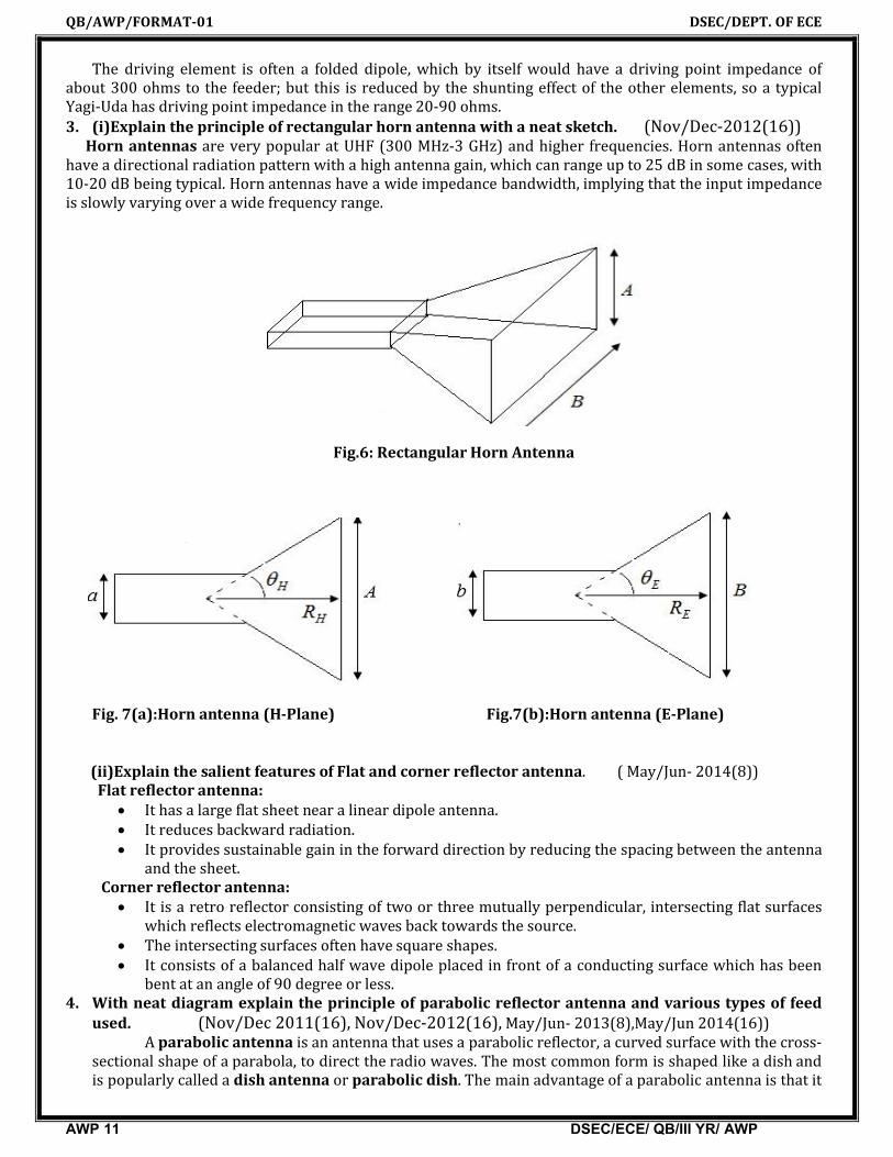
The driving element is often a folded dipole, which by itself would have a driving point impedance of about 300 ohms to the feeder; but this is reduced by the shunting effect of the other elements, so a typical Yagi-Uda has driving point impedance in the range 20-90 ohms.3. (i)Explain the principle of rectangular horn antenna with a neat sketch. (Nov/Dec-2012(16))
Horn antennas are very popular at UHF (300 MHz-3 GHz) and higher frequencies. Horn antennas often have a directional radiation pattern with a high antenna gain, which can range up to 25 dB in some cases, with 10-20 dB being typical. Horn antennas have a wide impedance bandwidth, implying that the input impedanceis slowly varying over a wide frequency range.
Fig.6: Rectangular Horn Antenna
Fig. 7(a):Horn antenna (H-Plane) Fig.7(b):Horn antenna (E-Plane)
(ii)Explain the salient features of Flat and corner reflector antenna. ( May/Jun- 2014(8)) Flat reflector antenna:
It has a large flat sheet near a linear dipole antenna. It reduces backward radiation. It provides sustainable gain in the forward direction by reducing the spacing between the antenna
and the sheet. Corner reflector antenna:
It is a retro reflector consisting of two or three mutually perpendicular, intersecting flat surfaces which reflects electromagnetic waves back towards the source.
The intersecting surfaces often have square shapes. It consists of a balanced half wave dipole placed in front of a conducting surface which has been
bent at an angle of 90 degree or less. 4. With neat diagram explain the principle of parabolic reflector antenna and various types of feed
used. (Nov/Dec 2011(16), Nov/Dec-2012(16), May/Jun- 2013(8),May/Jun 2014(16))A parabolic antenna is an antenna that uses a parabolic reflector, a curved surface with the cross-
sectional shape of a parabola, to direct the radio waves. The most common form is shaped like a dish and is popularly called a dish antenna or parabolic dish. The main advantage of a parabolic antenna is that it

QB/AWP/FORMAT-01 DSEC/DEPT. OF ECE
AWP 12 DSEC/ECE/ QB/III YR/ AWP
has high directivity. It functions similarly to a searchlight or flashlight reflector to direct the radio waves in a narrow beam, or receive radio waves from one particular direction only. Parabolic antennas have some of the highest gains, meaning that they can produce the narrowest beam widths, of any antenna type.
Fig.7: Parabolic Reflector antenna
Parabolic antennas are also classified by the type of feed, that is, how the radio waves are supplied to the antenna:
Axial or front feed – This is the most common type of feed, with the feed antenna located in front of the dish at the focus, on the beam axis, pointed back toward the dish.
Off-axis or offset feed – The reflector is an asymmetrical segment of a paraboloid, so the focus, and the feed antenna, are located to one side of the dish.
Cassegrain – In a Cassegrain antenna, the feed is located on or behind the dish, and radiates forward, illuminating a convex hyperboloidal secondary reflector at the focus of the dish.
Gregorian – Similar to the Cassegrain design except that the secondary reflector is concave, (ellipsoidal) in shape.
Fig.8: Parabolic Reflector antenna-feed types5. (i) Explain the image theory & its application in detail. (8)
Image Theory:The fields above a perfect ground plane from primary source acting in the presence of the perfect
ground plane are found by summing the contributions of the primary source and its image, each acting in free space.Application
Image theory is used in monopole antenna. By image theory, a monopole generates the exact same fields above the ground plane as a dipole.(ii) Explain the construction & principle of pyramidal Horn antenna . A pyramidal Horn antenna having aperture dimensions of a=5.2 cm & b=3.8 cm is used at a frequency of 10 GHz. Calculate its Gain and Half Power Beam width. (Nov/Dec- 2013(8))

QB/AWP/FORMAT-01 DSEC/DEPT. OF ECE
AWP 13 DSEC/ECE/ QB/III YR/ AWP
Horn antenna is flared in both E-plane and H-plane. This is a pyramidal horn, and has a width B and height A at the end of the horn.
Fig.9:Pyramidal Horn antenna6. (i)Discuss the various feed Techniques for Rectangular patch antenna with neat diagrams. (8)
The four most popular feed techniques used are the microstrip line, coaxial probe (both contacting schemes), aperture coupling and proximity coupling (both non-contacting schemes).
Micro strip (Offset Micro strip) Line Feed In this type of feed technique, a conducting strip is connected directly to the edge of the micro strip
patch
Coaxial Feed The Coaxial feed or probe feed is one of the most common techniques used for feeding micro strip
patch antennas.
Aperture Coupled Feed In aperture coupling , the radiating micro strip patch element is etched on the top of the antenna
substrate, and the micro strip feed line is etched on the bottom of the feed substrate in order to obtain aperture coupling.

QB/AWP/FORMAT-01 DSEC/DEPT. OF ECE
AWP 14 DSEC/ECE/ QB/III YR/ AWP
Proximity Coupled Feed This type of feed technique is also called as the electromagnetic coupling scheme.Two dielectric
substrates are used such that the feed line is between the two substrates and the radiating patch is on top of the upper substrate.
(ii) Find the diameter of a Dish antenna that will form a beam having 0.5 degree Half power Beam width (HPBW) at a frequency of 8.2 GHz. Assuming an efficiency constant of 0.6, calculate the antenna gain & effective aperture. (Nov/Dec- 2013(8))
Given Data:Hpbw=0.50 F = 8.2 Ghz K=0.6To Find:Antenna Gain=? Effective Aperture Ae = ?Solution:
Formula: HPBW= degree D = Gp = 6
7. Explain in detail about any two types of reflectors antenna. (May/Jun- 2012(16)) Flat reflector antenna:
It has a large flat sheet near a linear dipole antenna. It reduces backward radiation. It provides sustainable gain in the forward direction by reducing the spacing between the antenna
and the sheet. Corner reflector antenna:
It is a retro reflector consisting of two or three mutually perpendicular, intersecting flat surfaces which reflects electromagnetic waves back towards the source.
The intersecting surfaces often have square shapes. It consists of a balanced half wave dipole placed in front of a conducting surface which has been
bent at an angle of 90 degree or less.8. Describe the working of slot and reflector antennas. Derive the expressions for the radiation
resistance of these antennas. (16) A slot antenna consists of a metal surface, usually a flat plate, with one or more holes or slots cut out.
When the plate is driven as an antenna by a driving frequency, the slot radiates electromagnetic waves in

QB/AWP/FORMAT-01 DSEC/DEPT. OF ECE
AWP 15 DSEC/ECE/ QB/III YR/ AWP
a way similar to a dipole antenna. The shape and size of the slot, as well as the driving frequency, determine the radiation pattern.
9. Explain the radiation mechanism of slot antenna with diagram() ( May/Jun- 2011(16),Nov/Dec- 2012(16), App/May2013(8))
A slot antenna consists of a metal surface, usually a flat plate, with one or more holes or slots cut out. When the plate is driven as an antenna by a driving frequency, the slot radiates electromagnetic waves in a way similar to a dipole antenna. The shape and size of the slot, as well as the driving frequency, determine the radiation pattern.
Radiation is produced from both sides of the conductive sheet. If the 'slot' is 'boxed' with depth d =λ/4, the radiation available is outwards from the opening of the box.
As usual if more gain and directivity is required then it is common to have arrays of slot instead of single slot.
10. Explain the Numerical tool for antenna analysis. (May/jun- 2011(4))
The major categories of numerical methods used in antenna analysis and design are the finite differ-ence time domain method (FDTD) and the finite element method (FEM), which transform the differential equations of electro magnetics into difference equations, and integral equation methods, which transform the differential equations of electromagnetic through the use of a Green’s function into integral equations that can be solved using the method of moments (MoM).
UNIT III - ANTENNA ARRAYSPART-A (2 MARKS)
1. What is an Antenna array? (May/Jun 2011)Several antennas of similar type are arranged in a system, to radiate more in desired direction with
high gain, by combining their individual radiations in desired direction and cancelling the radiation in undesired direction. Such a system is called as antenna. Otherwise it is a system of similar antennas oriented similarly to get greater directivity in a desired direction.
2. What are the advantages of antenna arrays? ( May/June-2014) Antenna arrays is used to radiate more in desired direction with high gain Antenna array is used to get greater directivity in a desired direction.
3. A uniform linear array contains 50 isotropic radiation with an inter element spacing of λ/2.find the directivity of broadside form of arrays. (May/June-2013)

QB/AWP/FORMAT-01 DSEC/DEPT. OF ECE
AWP 16 DSEC/ECE/ QB/III YR/ AWP
4. Define Pattern Multiplication. (Apr/may-2011, Nov/Dec-2011,May/June-2007)The field pattern of an array of non isotropic but similar point sources is the product of the pattern of
the individual source and the pattern of an array of isotropic point sources having the same locations, relative amplitudes, and phase as the non-isotropic point sources.
5. Mention the features of radiation pattern multiplication principle. (Nov/Dec-2010)The principle of pattern multiplication provides a speedy method for sketching the radiation patterns
of complicated arrays just by inspection.6. What are the conditions to obtain end fire array pattern? (Nov/Dec-2012)
An array is said to be end fire if the direction of maximum radiation coincides with the array axis. Thus for an array to be end fire,=0 and θ= 00 or θ = 1800 in the maximum direction
7. What is Binomial array? ( May/June-2011)To reduce the side lobe level, John Stone proposed that sources have amplitudes proportional to the
coefficients of a binomial series. In Uniform array secondary lobes appear but principle lobe is sharp and narrow where as in Stone’s binomial array, width of beam widens but without secondary lobes.
8. Define array factor for linear array. (May/June-2012) The array factor quantifies the effect of combining radiating elements in an array without the element
specific radiation pattern taken into account. The overall radiation is defined by this array factor.9. What is tapering of arrays? (Nov/Dec-2017)
Tapering of array is a technique used for reduction of unwanted side lobes .The amplitude of currents in the linear array source is non-uniform; hence the central source radiates more energy than the ends. Tapering is done from center to end.
10. How can we eliminate minor lobes? (May/June-2013) secondary or side lobes in the linear broadside arrays are to be eliminated then the radiating sources must
have current amplitudes proportional to the coefficient of the above binomial series.11. What is the basic principle of antenna synthesis? (Nov/Dec-2013)
The Fourier series method is used to synthesize for the first category of requirements. The Dolph-Chebyshev method is used to synthesize for the second category of requirements
PART-B (16MARKS)
1. Obtain the expression for the field and the radiation pattern produced by a N element array of
infinitesimal with distance of separation λ/2 and currents of unequal magnitude and phase
shift 180 degree. (Nov/Dec-2007(16) (Nov/Dec-2012(16), (May/june2016(16))

QB/AWP/FORMAT-01 DSEC/DEPT. OF ECE
AWP 17 DSEC/ECE/ QB/III YR/ AWP
2. Two identical radiators are spaced d=3/4 meters apart and fed with currents of equal magnitude but with 1800 phase difference. Evaluate the resultant radiation identify the direction of maximum and minimum radiation. (Apr/May- 2015(16))
3. Describe the method of pattern multiplication. (Nov/Dec- 2014(8))The field pattern of an array of non isotropic but similar point sources is the product of the pattern of the individual source and the pattern of an array of isotropic point sources having the same locations, relative amplitudes, and phase as the non-isotropic point sources.
4. (i)Derive the expression for the field produced by a linear array and deduce it for an end fire array. (May/Jun- 2014(16))Linear array:
An array is said to be linear if the individual elements of vthe array are spaced equally along a line.The total far field pattern,= E e + E e + E e + E e + ⋯+ E e ( )
= E (e + e + e + e + ⋯+ e ( ) )Total phase difference of the fields at point p from adjacent sources,
Ψ = βcosθ+ α
The total far field of end fire array,
= sin Ψ2sinΨ2
(ii)Compare End fire and broadside array. (May/Jun- 2014(8))S.No. Broadside array End fire array
1.Array elements are fed with the
currents of equal amplitude and in phase
Array elements are fed with the currents of equal amplitude and out of
phase, = −2.
Maximum radiation is perpendicular to the direction of
array axis
Maximum radiation is directed the array axis
3. BWFN=± radians BWFN=±2 radians
5. Derive Array factor of a Uniform linear array. Explain the significance of array factor. (16) (AU ND 2013)
Array factor of a Uniform linear array:
The factor by which the array increases the field strength over that of a single element radiating the same total power is called as array factor.
= sin Ψ2sinΨ2

QB/AWP/FORMAT-01 DSEC/DEPT. OF ECE
AWP 18 DSEC/ECE/ QB/III YR/ AWP
= =sin Ψ2sinΨ2
= =(array factor)n
6. (i)What is binomial array? (May/June-2013(2))
To reduce the side lobe level, John Stone proposed that sources have amplitudes proportional to the coefficients of a binomial series. In Uniform array secondary lobes appear but principle lobe is sharp and narrow where as in Stone’s binomial array, width of beam widens but without secondary lobes.(ii)Draw the pattern of 10 element binomial array with spacing between the elements of 3/4 and /2. (May/June-2013(14))
7. Derive the expressions for field pattern of broad side array of n point sources. (May/June-2013(16))Broad side array:
It is defined as an arrangement in which the principle direction of radiation is perpendicular to the array axis and also to the plane containing the array element.the phase difference between adjacent elements is zero.Field pattern of broad side array:
E=cos (or) E=cos cos Maxima Direction : = 90 270 Minima Direction : = 0 180 Half Power Point Direction : = ±60 , ±120
8. For a 2 element linear array separated by a distance d=3/4, derive the field quantities and draw its radiation pattern for the phase difference of 450 (Nov/Dec-2012(16)) .
(16) (AU ND 2012)
E=cos= ; =
Field quantity , E=cos cos9. Derive the expressions for field pattern of end-fire array of n sources of equal amplitude and
spacing. (May/Jun- 2012(16))End Fire array:
It is defined as an arrangement in which the principle direction of radiation is coincides with array axis.

QB/AWP/FORMAT-01 DSEC/DEPT. OF ECE
AWP 19 DSEC/ECE/ QB/III YR/ AWP
Field pattern of broad side array:
E=2jE0 sin (or) E=sin cos Maxima Direction : = 0 180 Minima Direction : = 90 270 Half Power Point Direction : = ±60 , ±120
10. (i)Obtain the maxima, minima and half power points of two radiating point sources fed with equal in magnitude and phase current. (Nov/Dec- 2013(16))
Broad side array:It is defined as an arrangement in which the principle direction of radiation is perpendicular to
the array axis and also to the plane containing the array element.the phase difference between adjacent elements is zero.
Field pattern of broad side array:
E=cos (or) E=cos cos Maxima Direction : = 90 270 Minima Direction : = 0 180 Half Power Point Direction : = ±60 , ±120
(ii)Explain different properties of broadside and end fire arrays. (Nov/Dec- 2013(8)) Broadside array:o Array elements are fed with the currents of equal amplitude and in phaseo Maximum radiation is perpendicular to the direction of array axiso Beam Width Between First Null, BWFN=± radians End fire array
o Array elements are fed with the currents of equal amplitude and out of phase,= −o Maximum radiation is directed the array axis
o Beam Width Between First Null, BWFN=±2 radians

QB/AWP/FORMAT-01 DSEC/DEPT. OF ECE
AWP 20 DSEC/ECE/ QB/III YR/ AWP
UNIT IV - SPECIAL ANTENNASPART-A (2 MARKS)
1. Why frequency independent antennas are called so? ( Nov/Dec-2017) A Frequency independent antenna may be defined as the antenna for which the impedance and radian pattern (and hence D) remain constant as the function of the frequency.
2. State Rumsey principle on frequency independence. (Nov/Dec-2016, May/Jun-2016)
Rumsey’s principle states that if the shape of a given antenna is specified only in terms of angle, then the impedance and pattern properties of that antenna will be independent of frequency.
3. Define pitch angle of a helical antenna. The pitch angle of a helical antenna it is the angle between a line tangent to the helix wire and the plane normal to the helix axis.
4. Mention any two applications of helical antenna. (Nov/Dec-2012)Two applications of helical antenna are
(i) VHF transmission such as satellite communication(ii) Space telemetry link with ballistic missiles, satellites, etc.
5. What is the difference between Yagi Uda antenna and log periodic dipole array.S.No Yagi Uda Antenna Log Periodic Dipole Array
1 It is optimized for one frequency. It is optimized for wide range of frequency.
2.It will give higher gain at its optimal
frequency. It will have lower gain
3 it requires more number of elements.In lower frequency it require more number of elements compare to yogi uda antenna.
6. Why the Log periodic antenna called so? ( Nov/Dec-2011)The geometry of log periodic antenna is so chosen that electrical properties must repeat periodically
with logarithm of the frequency7. What is LPDA? (May/Jun- 2011(2))
LPDA means Log Periodic Dipole Array. It is defined as an antenna whose electrical properties repeat periodically with logarithm of the frequency.
8. What are the advantages of helical antenna?The advantages of helical antenna are
(i) It is very simple and wideband operation is possible.(ii) Its directivity is high.(iii)Circular polarization is obtained.
9. What is Babinet’s principle? (Nov/Dec-2011,May/June-2013, Nov/Dec-2017)Babinet’s principle states that when the field behind a screen with an opening is added to the field of
a complementary structure, the sum is equal to the field when there is not screen.10. For a 20 turn helical antenna operating at 3 GHz with circumference C=10 cm and the spacing
between the turns is 0.3 λ. Calculate the directivity. (May/Jun- 2011(8))Given:
S =0.3 λ. f= 3GHz, C= 10cm, N= 20 Turns Solution:
λ = = = 0.1 m
Directivity, D = = × × . × . ×. = 90
11. Mention any two applications of turnstile Antenna. ( May/June-2014) Two applications of turnstile Antenna are
FM transmission
Television Broad Casting.

QB/AWP/FORMAT-01 DSEC/DEPT. OF ECE
AWP 21 DSEC/ECE/ QB/III YR/ AWP
PART-B (16MARKS)
1. Explain the principle of operation of Log periodic antenna with neat schematic diagram.(App/May2008(8),(Apr/May- 2016) (May/Jun- 2012)
The log-periodic dipole array (LPDA) consists of a system of driven elements, but not all elements in the system are active on a single frequency of operation. The geometry of log periodic antenna is so chosen that electrical properties must repeat periodically with logarithm of the frequency. LPDA means Log Periodic Dipole Array. It is defined as an antenna whose electrical properties repeat periodically with logarithm of the frequency.
Fig.9: Log periodic antenna2. What are the importances’s of Helical antenna? Explain the construction and operation of
Helical antenna with neat sketch. (Apr/May- 2016),( Apr/May- 2011(16)Helical antenna:
The helix is a fundamental form of antenna of which loops and straight wires are limiting cases. When the helix is small compared to the wavelength, radiation is maximum normal to the helix axis. De-pending on the helix geometry, the radiation may, in theory, be elliptically, plane, or circularly polarized.
Fig.10: Helical antenna
Total Length of wire = nL Total axial length (A) = nS The importance’s of helical antenna are
(i) It is very simple and wideband operation is possible.(ii) Its directivity is high.(iii)Circular polarization is obtained.
3. Explain the measurement procedure for the measurement of VSWR and Radiation pattern.(May/june2016(16)) VSWR measurement:
o A VSWR measurement requires both a forward and reflected power measurement.o Therefore, errors from both the forward and reflected power measurements will combine to
make the return loss measurement error.
QB/AWP/FORMAT-01 DSEC/DEPT. OF ECE
AWP 22 DSEC/ECE/ QB/III YR/ AWP
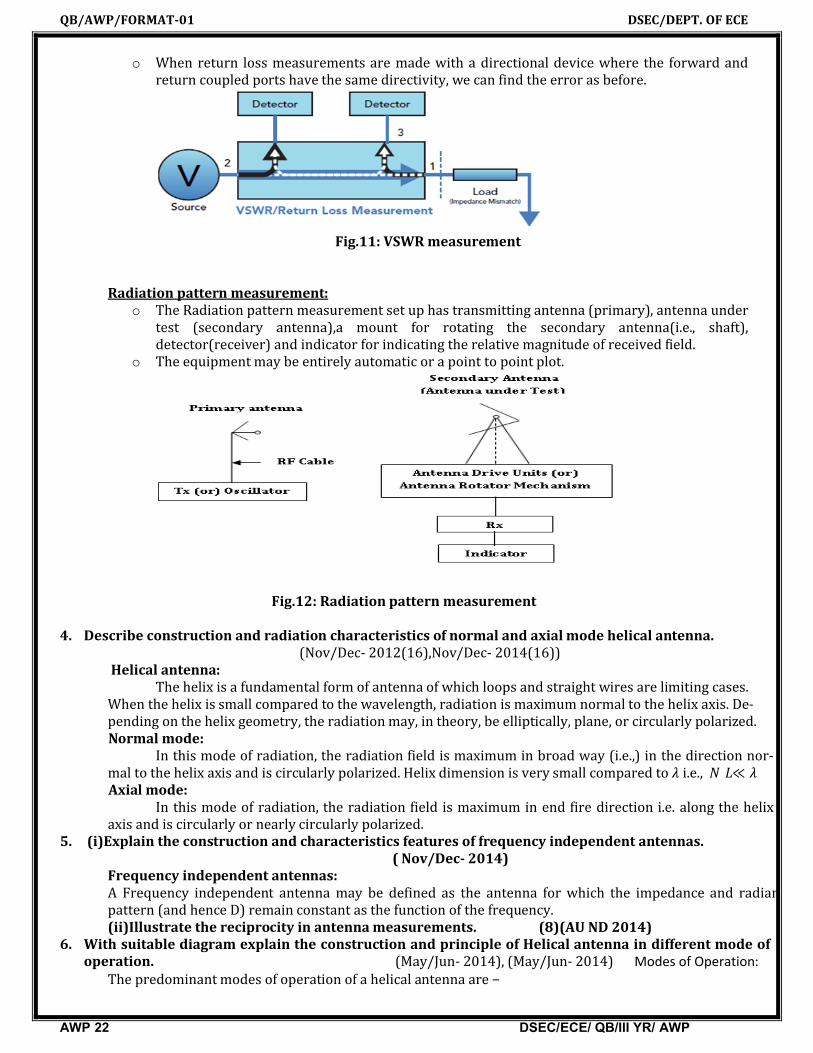
o When return loss measurements are made with a directional device where the forward and return coupled ports have the same directivity, we can find the error as before.
Fig.11: VSWR measurement
Radiation pattern measurement:
o The Radiation pattern measurement set up has transmitting antenna (primary), antenna under test (secondary antenna),a mount for rotating the secondary antenna(i.e., shaft), detector(receiver) and indicator for indicating the relative magnitude of received field.
o The equipment may be entirely automatic or a point to point plot.
Fig.12: Radiation pattern measurement 4. Describe construction and radiation characteristics of normal and axial mode helical antenna.
(Nov/Dec- 2012(16),Nov/Dec- 2014(16))Helical antenna:
The helix is a fundamental form of antenna of which loops and straight wires are limiting cases. When the helix is small compared to the wavelength, radiation is maximum normal to the helix axis. De-pending on the helix geometry, the radiation may, in theory, be elliptically, plane, or circularly polarized.
Normal mode:In this mode of radiation, the radiation field is maximum in broad way (i.e.,) in the direction nor-
mal to the helix axis and is circularly polarized. Helix dimension is very small compared to i.e., ≪ Axial mode:
In this mode of radiation, the radiation field is maximum in end fire direction i.e. along the helix axis and is circularly or nearly circularly polarized.
5. (i)Explain the construction and characteristics features of frequency independent antennas. ( Nov/Dec- 2014)
Frequency independent antennas:A Frequency independent antenna may be defined as the antenna for which the impedance and radian pattern (and hence D) remain constant as the function of the frequency.(ii)Illustrate the reciprocity in antenna measurements. (8)(AU ND 2014)
6. With suitable diagram explain the construction and principle of Helical antenna in different mode of operation. (May/Jun- 2014), (May/Jun- 2014) Modes of Operation:
The predominant modes of operation of a helical antenna are −

QB/AWP/FORMAT-01
AWP 23
Normal or perpendicular mode of radiation. Axial or end-fire or beam mode of radiation.
Normal mode In normal mode of radiation, the radiation field is normal to the helix axis. The radiated
are circularly polarized. This mode of radiation is obtained if the dimensions of helix are small compared to the wavelength. The radiation pattern of this hedipole and loop antenna.Axial mode In axial mode of radiation, the radiation is in the end
the waves are circularly or nearly circularly polarized. This mode of oraising the circumference to the order of one wavelength λ/4. The radiation pattern is broad and directional along the axial beam producing minor lobes
at oblique angles.7. Explain the measurement of antenna gain.
At high frequencies, the gain measurement is done using direct comparison method. In thisthod, the gain measurement is done by comparing the strengths of the signals ceived by the antenna under
The antenna whose gain is accurately known and can be used for the gain mantennas is called standard gain antenna.
At high frequency, the universallyof gain measurement by the comparison method is as shown in
Fig.13. Setup for antenna gain measurement
8. (i)Draw a neat block diagram for antenna radiation pattern measurement.detail.
DSEC/ECE/ QB/III YR/ AWP
or perpendicular mode of radiation.fire or beam mode of radiation.
In normal mode of radiation, the radiation field is normal to the helix axis. The radiated are circularly polarized. This mode of radiation is obtained if the dimensions of helix are small
compared to the wavelength. The radiation pattern of this helical antenna is a combination of short
of radiation, the radiation is in the end-fire direction along the helical axis the waves are circularly or nearly circularly polarized. This mode of operation is obtained by raising the circumference to the order of one wavelength (λ) and spacing of approximately
. The radiation pattern is broad and directional along the axial beam producing minor lobes
antenna gain. (May/At high frequencies, the gain measurement is done using direct comparison method. In thisthod, the gain measurement is done by comparing the strengths of the signals ceived by the antenna under test and the standard gain antenna.
is accurately known and can be used for the gain mstandard gain antenna.
universally accepted standard gain antenna is the horn antenof gain measurement by the comparison method is as shown in the Fig.
Fig.13. Setup for antenna gain measurement
(i)Draw a neat block diagram for antenna radiation pattern measurement. Explain the procedure in ( Nov/Dec- 2013) ,(Apr/may-
DSEC/DEPT. OF ECE
ECE/ QB/III YR/ AWP
In normal mode of radiation, the radiation field is normal to the helix axis. The radiated wavesare circularly polarized. This mode of radiation is obtained if the dimensions of helix are small
lical antenna is a combination of short
fire direction along the helical axis and peration is obtained by
and spacing of approximately . The radiation pattern is broad and directional along the axial beam producing minor lobes
ay/Jun- 2014)At high frequencies, the gain measurement is done using direct comparison method. In this me-thod, the gain measurement is done by comparing the strengths of the signals transmitted or re-
is accurately known and can be used for the gain measurement of other
the horn antenna. The set up
Explain the procedure in 2013)

QB/AWP/FORMAT-01 DSEC/DEPT. OF ECE
AWP 24 DSEC/ECE/ QB/III YR/ AWP
(ii)Give an account on “Helical Antenna”. (6) (AU ND2013)Helical antenna:
The helix is a fundamental form of antenna of which loops and straight wires are limiting cases. When the helix is small compared to the wavelength, radiation is maximum normal to the helix axis. De-pending on the helix geometry, the radiation may, in theory, be elliptically, plane, or circularly polarized.
9. With necessary illustrations explain the radiation characteristics of multi element log periodic antenna and mention its possible applications. (Nov/Dec-2012(16))
The log-periodic dipole array (LPDA) consists of a system of driven elements, but not all elements in the system are active on a single frequency of operation. The geometry of log periodic antenna is so chosen that electrical properties must repeat periodically with logarithm of the frequency.The principle of operations is works in three main region.(i)inactive region(ii)active region (iii) inactive regionApplications:It is used in UHF Terrestrial TV(he antenna is sometimes seen in the form of UHF terrestrial antenna applications.)
10. Explain in detail about(i)Directivity measurement (May/June-2012(8))
(ii)Gain measurement. (May/June-2012 (8))
(i)Directivity measurement The directivity, D of an antenna is its maximum directive gain. It is obtained from the field pattern
of the antenna. From the measured patterns and their beam width in both the principal planes, D is ob-tained. The principal planes are E-plane and H-plane. i. E-plane pattern: For a linearly polarized antenna, E-Plane pattern is defined as a pattern in the
plane which contains the electric field and the direction of maximum radiation. ii. H-plane pattern: For a linearly polarized antenna, the H-plane pattern is defined as the pattern in
the plane which contains the magnetic field and the direction of maximum radiation. (ii)Gain measurement.
At high frequencies, the gain measurement is done using direct comparison method. In thismethod, the gain measurement is done by comparing the strengths of the signals transmitted or received by the antenna under test and the standard gain antenna. The antenna whose gain is accurately known and can be used for the gain measurement of other antennas is called standard gain antenna. At high frequency, the universally accepted standard gain antenna is the horn antenna.

QB/AWP/FORMAT-01 DSEC/DEPT. OF ECE
AWP 25 DSEC/ECE/ QB/III YR/ AWP
UNIT V- PROPAGATION OF RADIO WAVESPART-A (2 MARKS)
1. Explain the term: Duct propagation(May/June-2007,Nov/Dec2007, Nov/Dec-2016)The portion which has different refractive index will act as a propagating channel called as duct. Under
such conditions the wave tends to be trapped or guided along the duct, as a wave is guided by a leaky wave guide. Such propagation is called duct or trapping propagation or super refraction.
2. What are the specific features of troposcatter propagation? (May/Jun- 2016) The specific features are, (i) It is useful for propagation in the range of 100MHz to 10GHz. (ii) It produces undesirable noise and fading which may be minimized to certain extent by diversity reception. (iii) The field strength received is usually on the order of d1/7or d1/8 where d is the
distance between the transmitter and receiver. (iv) Since the signal strength very weak, high gain antennas are required for
reception. (v) The propagation exhibits seasonal variation.3. Find the range of LOS system when they receive and transmit antenna heights are 10m and 100m
respectively. (May/June-2016)
Line of sight range is given by,d = 4.12[√ht+√hr] Km = 4.12[√10+√100]Km
d= 54.23Km4. What is meant by faraday rotation (Apr/may-2011, Nov/Dec-2011)
The rotation of plane of polarization of linearly polarized wave propagating through magnetized dielectric medium is known as Faraday’s rotation.
5. Define Virtual height. (May/June-2012)Virtual height of a antenna is the apparent height of a layer in the ionosphere determined from the
time required for a radio pulse to travel to the layer and return, assuming that the pulse propagates at the speed of light. It is also known as equivalent height.
6. Differentiate virtual height from actual height. ( May/Jun- 2014) Virtual Height will always be greater than actual height. The virtual height has the greatest advantage
of being easily measured and its very useful in transmission path calculation. 7. What is Gyro frequency? (Nov/Dec-2013)
Frequency whose period is equal to the period of an electron in its orbit under the influence of the Earth’s magnetic flux density B is called Gyro frequency.
8. Define Critical frequency. (Nov/Dec-2011)Each Ionosheric layer has a maximum frequency at which radio waves can be transmitted vertically
and refracted back to earth. This frequency is known as the critical frequency. It is otherwise defined as limiting frequency at which a wave is reflected by, and above which it penetrates through an Ionospheric layer.
Fc =9Nm
Where, Nm is maximum ion density.9. Define optimum working frequency. (April/may-2012)
Optimum working frequency is the frequency that is normally used for ionospheric transmission. It is chosen to be about 1.5% less than MUF.(Maximum usable frequency). This frequency is called OTF.
10. Define Maximum usable frequency. (April/may-2011)

QB/AWP/FORMAT-01 DSEC/DEPT. OF ECE
AWP 26 DSEC/ECE/ QB/III YR/ AWP
It is the upper frequency limit that can be used for transmission between two points at a specified time, independent of transmitter power.
Maximum usable frequency, fmuf = fc 1+d2/4h Where, fc = out off or critical frequency
d = Skip distance, h= Height of the layer from ground
11. What is meant by skip distance? ( May/June-2007,Nov/Dec-2007, May/June-2012, Nov/Dec-2012, Nov/Dec-2017)
Skip distance defined as the minimum distance from the transmitter at which a sky wave of given frequency is returned to earth by the ionosphere. It is also called as skip zone.
12. Explain the term: Skip Zone.Skip zone defined as the minimum distance from the transmitter at which a sky wave of given
frequency is returned to earth by the ionosphere. It is also called as skip distance. 13. What is fading? And how it is compensated. (May/June-2013)
Fading is the distortion that a radio wave signal experiences over certain propagation media.
PART-B (16MARKS)
1. (i)Discuss the effects of earth’s magnetic field on ionosphere radio wave propagation.(Apr/May2011 (8), (Nov/Dec 2011(8), May/Jun- 2016(8))
A radio wave propagating in the atmosphere which is not ionized is not affected by the earth’s magnetic field. The earth’s magnetic field splits up the incident waves into two components i.e., the ordinary and extra ordinary waves. the properties of ordinary wave are same as the waves without superimposed magnetic field.
= =
(ii)Describe the troposphere and explain how ducts can be used for microwave propagation.(Nov/Dec-2012(8), (May/Jun- 2016)
In telecommunications, an atmospheric duct is a horizontal layer in the lower atmosphere in which the vertical refractive index gradients are such that radio signals (and light rays) are guided or ducted, tend to follow the curvature of the Earth, and experience less attenuation in the ducts than they would if the ducts were not present. The duct acts as an atmospheric dielectric waveguide and limits the spread of the wave front to only the horizontal dimension
2. (i) In the ionospheric propagation, consider that the reflection takes place at a height of 400km and the maximum density in the ionosphere corresponds to a refractive index of 10mHz.Determine the ground range for which this frequency is the MUF.Take earth’s curvature into consideration. (Apr/May-2011(16) (May/june2016(6))
(ii)Describe the structure of the atmosphere and explain each layer in detail. (10) (May/Jun- 2012) (May/Jun- 2016) Structure of the atmosphere:
Earth's atmosphere extends more than 560 kilometers (348 miles) above the planet's surface and is divided into three layers
Troposphere:

QB/AWP/FORMAT-01 DSEC/DEPT. OF ECE
AWP 27 DSEC/ECE/ QB/III YR/ AWP
Almost all weather occurs in the troposphere, the lowest layer of the atmosphere, which extends from the surface up to 8 to 16 kilometers above Earth's surface
Stratosphere:the stratosphere, extends upward from the tropopause to 50 kilometers. In the stratosphere
temperatures increase with altitude because of absorption of sunlight by stratospheric ozone. Mesosphere:
the mesosphere, temperatures once again fall with increasing altitude, to a low of about -93°C at an altitude of 85 kilometers.
3. (i)Draw the structure of ionosphere and explain the mechanism of ionosphere propagation. (Apr/May2011 (8), (Nov/Dec 2011(8), (Nov/Dec-2012(6),(Apr/May- 2015)
The upper part of the atmosphere where the ionization is possible is known as ionosphere. The upper part of the earth’s atmosphere absorbs large quantities of radiant energy from the sun. It heats the atmosphere and also produces ionizations i.e., formation of negative and positive ions occurs. The ionized region contains free electrons, +ve and –ve. the most important ionizing agents are ultra violet radiations (UV), , rays ,cosmic rays etc.
There are 3 principle layers during day time and are called E,F1,and F2 layers
(ii)Explain the effects of magnetic fields on EM wave propagation. (App/May2011 (8 ) ,Apr/May-2015) ,(May/Jun- 2012)A radio wave propagating in the atmosphere which is not ionized is not affected by the earth’s magnetic field.
The earth’s magnetic field splits up the incident waves into two components i.e., the ordinary and extra ordinary waves.the properties of ordinary wave are same as the waves without superimposed magnetic field.
= =
4. (i)Explain the mechanism of tropospheric propagation. (6) (AU AM 2015)
Tropospheric propagation describes electromagnetic propagation in relation to the troposphere. The service area from a VHF or UHF radio transmitter extends to just beyond the optical horizon, at which point signals start to rapidly reduce in strength. Viewers living in such a "deep fringe" reception area will notice that during certain conditions, weak signals normally masked by noise increase in signal strength to allow quality reception. Such conditions are related to the current state of the troposphere.
(ii)Explain the terms:(1)MUF(2)Virtual height(3)Duct propagation

QB/AWP/FORMAT-01 DSEC/DEPT. OF ECE
AWP 28 DSEC/ECE/ QB/III YR/ AWP
(4)Skip distance(5)Fading (App/May2011(10),(Nov/Dec2011(6)),(Nov/Dec-2012(8),(May/june2014(8)
App/May2015(10))
(1)MUF:It is the upper frequency limit that can be used for transmission between two points at a specified
time, independent of transmitter power.Maximum usable frequency, fmuf = fc 1+d2/4h
Where, fc = out off or critical frequencyd = Skip distance, h= Height of the layer from ground
(2)Virtual height:Virtual height of a antenna is the apparent height of a layer in the ionosphere determined from the time
required for a radio pulse to travel to the layer and return, assuming that the pulse propagates at the speed of light. It is also known as equivalent height.
(3) Duct propagation:The portion which has different refractive index will act as a propagating channel called as duct. Under
such conditions the wave tends to be trapped or guided along the duct, as a wave is guided by a leaky wave guide. Such propagation is called duct or trapping propagation or super refraction.
(4)Skip distance:Skip distance defined as the minimum distance from the transmitter at which a sky wave of given
frequency is returned to earth by the ionosphere. It is also called as skip zone.(5)Fading:
Fading is the distortion that a radio wave signal experiences over certain propagation media.
5. (i)Explain in detail the mechanism of space wave propagation over ideal flat earth with a neat sketch. (Nov/Dec- 2014(8))
The high frequency electromagnetic wave is not reflected back by the ionosphere, so to use high frequency electromagnetic wave in communication we used space wave propagation. Space waves are used in two types of communication
Line-of-sight (LOS) propagation. Satellite communication
(ii)Discuss the factors that give rise to fading in ionospheric radio wave propagation. (Nov/Dec- 2014(8))
Variation over time or distance of received signal power caused by changes in the transmission medium or path(s)
o In a fixed environment: Changes in atmospheric conditions
o In a mobile environment: Multipath propagation
6. (i)Describe the significant features of ground wave propagation. (Nov/Dec 2011(10), (Nov/Dec-2014(8))
o It Follows contour of the eartho It Can Propagate considerable distanceso Frequencies up to 2 MHzo Example: AM radio

QB/AWP/FORMAT-01 DSEC/DEPT. OF ECE
AWP 29 DSEC/ECE/ QB/III YR/ AWP
(ii)Obtain an expression for the refractive index of an ionospheric layer. (Nov/Dec- 2014(8))
The rotation of plane of polarization of linearly polarized wave propagating through magnetized dielectric medium is known as Faraday’s rotation.
7. (i)Describe the space wave propagation and explain the importance of line of sight propagation. (May/Jun- 2014(8))
The high frequency electromagnetic wave is not reflected back by the ionosphere, so to use high fre-quency electromagnetic wave in communication we used space wave propagation. Space waves are used in two types of communication
Line-of-sight (LOS) propagation. Satellite communication
Line-of-sight (LOS) propagation
In line of sight propagation a space wave travels in a straight line from transmitting antenna to the receiving antenna. At frequencies below 40 MHz . For this type of propagation there should be no obstacle between the transmitting antenna and the receiving antenna. In line-of-sight propagation, space waves are very powerful, the signals are very clear, the bandwidth is very large and a huge amount of information can be transmitted.
Working of satellite communicationIn satellite communication the process of transmitting signal wave towards the satellite is known as
up linking. The satellite has a receiver that receives the incoming message signal and then amplifies the signal and the frequency of the signal is also changed, after which the message signal is transmitted back to the earth. This type of propagation is known as space wave propagation and as satellite is used the
communication is called as satellite communication.
(ii)Explain the following terms with diagram :(1)Duct propagation (2)Critical frequency (3)Skip zone. (May/J un-2014(8))
(1)Duct propagation The portion which has different refractive index will act as a propagating channel called as duct. Under
such conditions the wave tends to be trapped or guided along the duct, as a wave is guided by a leaky wave guide. Such propagation is called duct or trapping propagation or super refraction.
(2)Critical frequency Each Ionosheric layer has a maximum frequency at which radio waves can be transmitted vertically
and refracted back to earth. This frequency is known as the critical frequency. It is otherwise defined as limiting frequency at which a wave is reflected by, and above which it penetrates through an Ionospheric layer.
QB/AWP/FORMAT-01 DSEC/DEPT. OF ECE
AWP 30 DSEC/ECE/ QB/III YR/ AWP
Fc =9Nm
Where, Nm is maximum ion density. (3)Skip zone
Skip distance defined as the minimum distance from the transmitter at which a sky wave of given frequency is returned to earth by the ionosphere. It is also called as skip zone.
8. (i)Discuss the factors that are involved in the propagation of radio waves.(6) (Nov/Dec2013(8))
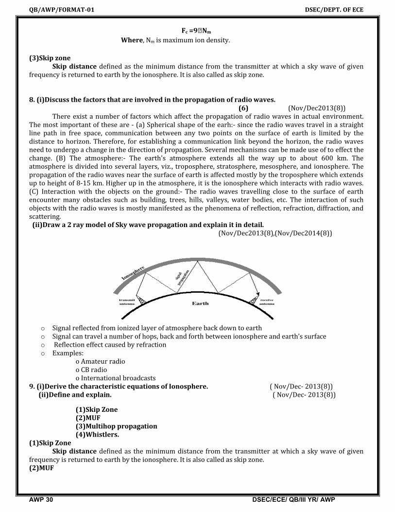
There exist a number of factors which affect the propagation of radio waves in actual environment. The most important of these are - (a) Spherical shape of the earh:- since the radio waves travel in a straight line path in free space, communication between any two points on the surface of earth is limited by the distance to horizon. Therefore, for establishing a communication link beyond the horizon, the radio waves need to undergo a change in the direction of propagation. Several mechanisms can be made use of to effect the change. (B) The atmosphere:- The earth's atmosphere extends all the way up to about 600 km. The atmosphere is divided into several layers, viz., troposphere, stratosphere, mesosphere, and ionosphere. The propagation of the radio waves near the surface of earth is affected mostly by the troposphere which extends up to height of 8-15 km. Higher up in the atmosphere, it is the ionosphere which interacts with radio waves. (C) Interaction with the objects on the ground:- The radio waves travelling close to the surface of earth encounter many obstacles such as building, trees, hills, valleys, water bodies, etc. The interaction of such objects with the radio waves is mostly manifested as the phenomena of reflection, refraction, diffraction, and scattering. (ii)Draw a 2 ray model of Sky wave propagation and explain it in detail.
(Nov/Dec2013(8),(Nov/Dec2014(8))
o Signal reflected from ionized layer of atmosphere back down to eartho Signal can travel a number of hops, back and forth between ionosphere and earth’s surfaceo Reflection effect caused by refractiono Examples:
o Amateur radioo CB radioo International broadcasts
9. (i)Derive the characteristic equations of Ionosphere. ( Nov/Dec- 2013(8)) (ii)Define and explain. ( Nov/Dec- 2013(8))
(1)Skip Zone(2)MUF(3)Multihop propagation(4)Whistlers.
(1)Skip ZoneSkip distance defined as the minimum distance from the transmitter at which a sky wave of given
frequency is returned to earth by the ionosphere. It is also called as skip zone.(2)MUF

QB/AWP/FORMAT-01 DSEC/DEPT. OF ECE
AWP 31 DSEC/ECE/ QB/III YR/ AWP
It is the upper frequency limit that can be used for transmission between two points at a specified time, independent of transmitter power.
Maximum usable frequency, fmuf = fc 1+d2/4h Where, fc = out off or critical frequency
d = Skip distance, h= Height of the layer from ground
(3)Multi hop propagation:The coverage of transmission distance between transmitter and receiver in more than one hop (jump)
is known as multi hop propagation.(4)Whistlers:
It is a whistling tone with gradually falling pitch..It occurs due to transient electromagnetic disturbances.
10. (i)Describe the Troposcatter propagation. (May/Jun- 2013(8))The troposphere is the lowest portion of the atmosphere. Most of our weather takes place in the
troposphere. It contains 80% of the atmosphere's mass and 99% of its water vapor. Troposcatter occurs when two stations both point their antennas at a common volume in the troposphere, and that volume of the troposphere redirects the signal directed into it by one station towards the receiving antenna of the second station. The useful range of troposcatter is roughly 100 to 700 km, and it can be used from 144 MHz through 10 GHz.
(ii)Explain the effect of Earth’s magnetic field on ground wave propagation. ( Nov/Dec- 2013(8))
A radio wave propagating in the atmosphere which is not ionized is not affected by the earth’s magnetic field. The earth’s magnetic field splits up the incident waves into two components i.e., the ordinary and extra ordinary waves.the properties of ordinary wave are same as the waves without superimposed magnetic field.
= =
11. Describe the structure of the atmosphere and specify the factors affecting the radio wave propagation. (May/Jun- 2012(16)) since the medium between transmitting and receiving antennas plays an important role, it is necessary to study the medium above earth, through which the radio waves propagate. the atmosphere consists of three major regions(i)troposphere(ii)ionosphere(iii)outer atmosphere.
12.(i)Explain the structure of the ionosphere with neat diagram. ( Nov/Dec- 2012(6))
The upper part of the atmosphere where the ionization is possible is known as ionosphere. The upper part of the earth’s atmosphere absorbs large quantities of radiant energy from the sun. It heats the atmosphere and also produces ionizations i.e., formation of negative and positive ions occurs. The ionized region contains free electrons, +ve and –ve. the most important ionizing agents are ultra violet radiations (UV), , rays ,cosmic rays etc. There are 3 principle layers during day time and are called E,F1,and F2 layers
(ii)Why do we use high frequency waves in sky wave propagation? Explain the mechanism of propagation. ( Nov/Dec- 2012(6))
Sky wave propagation is suitable for frequencies between 2 to 30 MHz, so this mode of propagation is also called as short wave propagation. Since sky wave propagation takes place after reflection from theionosphere, it is also called as ionospheric propagation. since long distance point to point communication is possible with sky wave propagation.