diagnoscsandprognoscs** … and prognostics of electro-mechanical actuators, eu/ieee fdd workshop,...
TRANSCRIPT

Diagnostics and Prognostics of Electro-Mechanical Actuators, EU/IEEE FDD Workshop, Toulouse, France, Oct 23-26, 2012
Diagnos(cs and Prognos(cs of Electro-‐Mechanical Actuators
Edward Balaban, NASA Ames Research Center
https://ntrs.nasa.gov/search.jsp?R=20130013551 2018-06-23T01:31:50+00:00Z

Diagnostics and Prognostics of Electro-Mechanical Actuators, EU/IEEE FDD Workshop, Toulouse, France, Oct 23-26, 2012 2
Team Members
q Edward Balaban
q Sriram Narasimhan
q Abhinav Saxena
q Indranil Roychoudhury
q Michael Koopmans (student intern)
q Zachary Ballard (student intern)
q Sterling Clarke (student intern)
2

Diagnostics and Prognostics of Electro-Mechanical Actuators, EU/IEEE FDD Workshop, Toulouse, France, Oct 23-26, 2012 3
Outline
q NASA Ames DiagnosFcs and PrognosFcs Group
q EMA health management -‐ moFvaFon and approach
q Data collecFon
q DiagnosFc system development
q PrognosFc system development
q Laboratory experiments
q Flight experiments
q Summary

Diagnostics and Prognostics of Electro-Mechanical Actuators, EU/IEEE FDD Workshop, Toulouse, France, Oct 23-26, 2012 4
Terminology
Fault DetecFon
Diagnosis
Prognosis
Decision Making
Diagnostics and Prognostics of Electro-Mechanical Actuators, EU/IEEE FDD Workshop, Toulouse, France, Oct 23-26, 2012 5
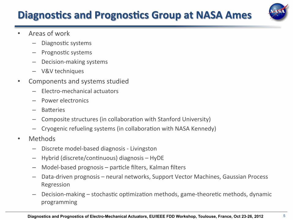
Diagnos(cs and Prognos(cs Group at NASA Ames • Areas of work
– DiagnosFc systems – PrognosFc systems – Decision-‐making systems – V&V techniques
• Components and systems studied – Electro-‐mechanical actuators – Power electronics – BaPeries – Composite structures (in collaboraFon with Stanford University) – Cryogenic refueling systems (in collaboraFon with NASA Kennedy)
• Methods – Discrete model-‐based diagnosis -‐ Livingston – Hybrid (discrete/conFnuous) diagnosis – HyDE – Model-‐based prognosis – parFcle filters, Kalman filters – Data-‐driven prognosis – neural networks, Support Vector Machines, Gaussian Process
Regression – Decision-‐making – stochasFc opFmizaFon methods, game-‐theoreFc methods, dynamic
programming

Diagnostics and Prognostics of Electro-Mechanical Actuators, EU/IEEE FDD Workshop, Toulouse, France, Oct 23-26, 2012 6
Diagnos(cs and Prognos(cs Group (con(nued)
• Test faciliFes – EMA testbeds – ADAPT (Advanced DiagnosFcs and PrognosFcs Testbed) – aircraY power distribuFon – Electrical baPery aging testbed – Electronics aging testbeds (for MOSFETs, IGBTs, and capacitors) – An environmental chamber (temperature, pressure, and humidity)
• Test vehicles – K11 planetary rover prototype – Edge 540 UAV (NASA Langley) – UH-‐60 Blackhawk helicopters (US Army at NASA Ames)

Diagnostics and Prognostics of Electro-Mechanical Actuators, EU/IEEE FDD Workshop, Toulouse, France, Oct 23-26, 2012 7
Mo(va(on for EMA Health Management
7
• EMA are becoming a component criFcal to aircraY and spacecraY safety
• Performance data on EMA, both laboratory and in-‐flight, is scarce
• A variety of fault types can occur (discrete/conFnuous, abrupt/incipient) in a variety of subsystems (mechanical, electrical, control system, or sensor).
• We need to be able to diagnose faults quickly and accurately, to enable prognosis and miFgaFon
• We believe that collecFng and tesFng on high-‐quality nominal and fault-‐injected data is essenFal to developing effecFve EMA health management systems
Diagnostics and Prognostics of Electro-Mechanical Actuators, EU/IEEE FDD Workshop, Toulouse, France, Oct 23-26, 2012 8
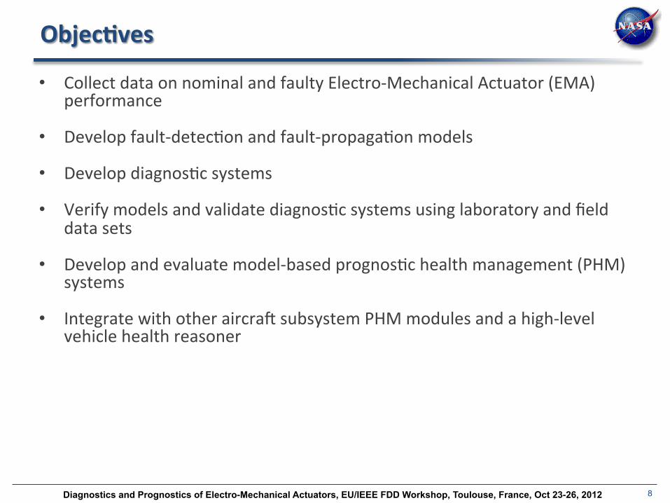
Objec(ves
• Collect data on nominal and faulty Electro-‐Mechanical Actuator (EMA) performance
• Develop fault-‐detecFon and fault-‐propagaFon models
• Develop diagnosFc systems
• Verify models and validate diagnosFc systems using laboratory and field data sets
• Develop and evaluate model-‐based prognosFc health management (PHM) systems
• Integrate with other aircraY subsystem PHM modules and a high-‐level vehicle health reasoner

Diagnostics and Prognostics of Electro-Mechanical Actuators, EU/IEEE FDD Workshop, Toulouse, France, Oct 23-26, 2012 9
Nominal and fault modeling
• Fault analysis
• Lubricant effects modeling
• Micro-‐scale mechanical modeling
• Wear modeling
• Winding shorts modeling
• FuncFonal system models

Diagnostics and Prognostics of Electro-Mechanical Actuators, EU/IEEE FDD Workshop, Toulouse, France, Oct 23-26, 2012 10
Experimental Data Collec(on
Capabili(es:
• 5 metric ton load capacity
• AccommodaFon of test actuators of various sizes and configuraFons
• Custom moFon and load profiles
Sensor Suit:
• VibraFon
• Load
• Temperatures sensors
• High-‐precision posiFon sensors
• Current sensors

Diagnostics and Prognostics of Electro-Mechanical Actuators, EU/IEEE FDD Workshop, Toulouse, France, Oct 23-26, 2012 11
The FLEA (Flyable Electromechanical Actuator)
• Allows diagnosFc and prognosFc experiment execuFon in
realisFc condiFons
• Designed to funcFon as an unobtrusive secondary payload
• No aircraY modificaFons are required
• Experiments can be done during virtually any flight opportunity
• Designed to be quickly adaptable to different types of aircraY
• Faults can be injected without endangering the host aircraO

Diagnostics and Prognostics of Electro-Mechanical Actuators, EU/IEEE FDD Workshop, Toulouse, France, Oct 23-26, 2012 12
The hardware
12
Sensor suite • High Speed (20kHz)
• Accelerometers
• Low speed (1kHz)
§ current sensors
§ voltage sensors
§ posiFon sensors § temperature
sensors
§ load cell
Major hardware components • Two test actuators
• Load actuator
• MagneFc coupling system
• MoFon controller
• Central computer
• DAQ system • Sensors
• Data storage system
Major soOware components • Control system
• GUI
• Signal processing and data extracFon
• DiagnosFc system
• PrognosFc system • Experiment recording and
data archival system

Diagnostics and Prognostics of Electro-Mechanical Actuators, EU/IEEE FDD Workshop, Toulouse, France, Oct 23-26, 2012 13
Opera(on
• An aircraY actuator is selected to be “mimicked”
• FLEA operates in parallel with the selected actuator, execuFng the same moFon
and load profiles
• Load profiles are calculated from aerodynamic data and scaled down for the FLEA
range, if necessary
• One test actuator is kept nominal, the other one is fault-‐injected
• Load path can be switched in-‐flight from
the nominal test actuator to the fault-‐
injected one, via the magneFc coupling
Diagnostics and Prognostics of Electro-Mechanical Actuators, EU/IEEE FDD Workshop, Toulouse, France, Oct 23-26, 2012 14
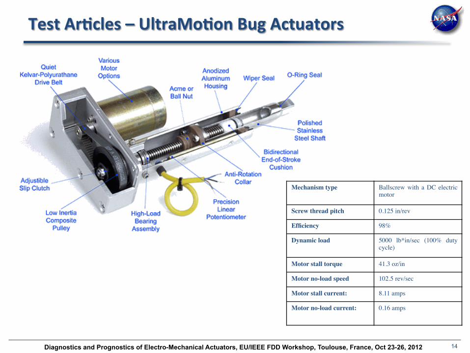
Test Ar(cles – UltraMo(on Bug Actuators
Mechanism type Ballscrew with a DC electric motor
Screw thread pitch 0.125 in/rev Efficiency 98% Dynamic load 5000 lb*in/sec (100% duty
cycle) Motor stall torque 41.3 oz/in Motor no-load speed 102.5 rev/sec Motor stall current: 8.11 amps Motor no-load current: 0.16 amps
Diagnostics and Prognostics of Electro-Mechanical Actuators, EU/IEEE FDD Workshop, Toulouse, France, Oct 23-26, 2012 15
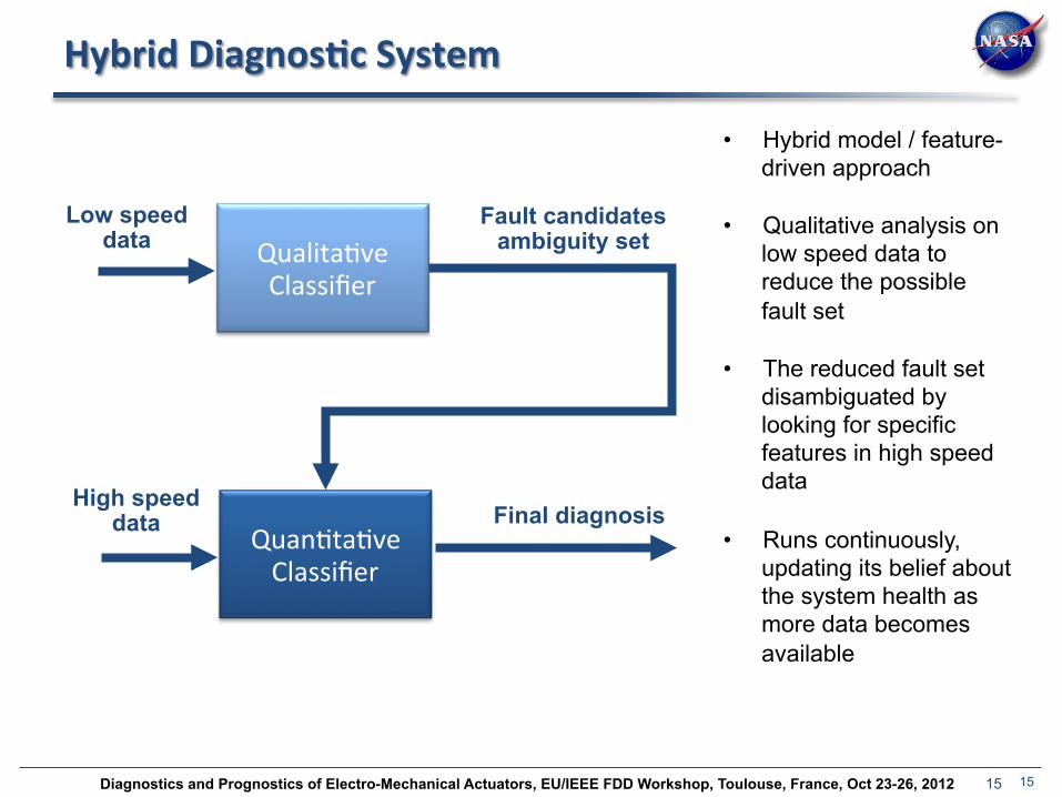
Hybrid Diagnos(c System
15
• Hybrid model / feature-driven approach
• Qualitative analysis on low speed data to reduce the possible fault set
• The reduced fault set disambiguated by looking for specific features in high speed data
• Runs continuously, updating its belief about the system health as more data becomes available
QualitaFve Classifier
QuanFtaFve Classifier
Low speed data
High speed data
Fault candidates ambiguity set
Final diagnosis

Diagnostics and Prognostics of Electro-Mechanical Actuators, EU/IEEE FDD Workshop, Toulouse, France, Oct 23-26, 2012 16
Hybrid Diagnos(c System (more details)
• Qualita(ve analysis
– QualitaFve signatures of fault derived from model as well as data from faulty runs.
– An observer uses differenFal equaFons to track plant behavior
– QualitaFve symbols generated when predicted behavior (from observer) is not
consistent with actual behavior (sensor data)
– Comparison of symbols and signatures results in reducFon of possible fault set
16
• Disambigua(on
– Features selected based on diagnosability analysis of qualitaFve approach
– Features specific to selected ambiguity group

Diagnostics and Prognostics of Electro-Mechanical Actuators, EU/IEEE FDD Workshop, Toulouse, France, Oct 23-26, 2012 17
Qualita(ve Fault Diagnos(c Architecture
System receives inputs, produces outputs
Abstract magnitude and slope of fault deviaFons using + (increase), – (decrease), and 0 (no change)
symbols
Detect faults based on staFsFcally significant deviaFons from model-‐predicted behavior
Isolate faults by comparing to model-‐
predicted fault signatures
Diagnostics and Prognostics of Electro-Mechanical Actuators, EU/IEEE FDD Workshop, Toulouse, France, Oct 23-26, 2012 18
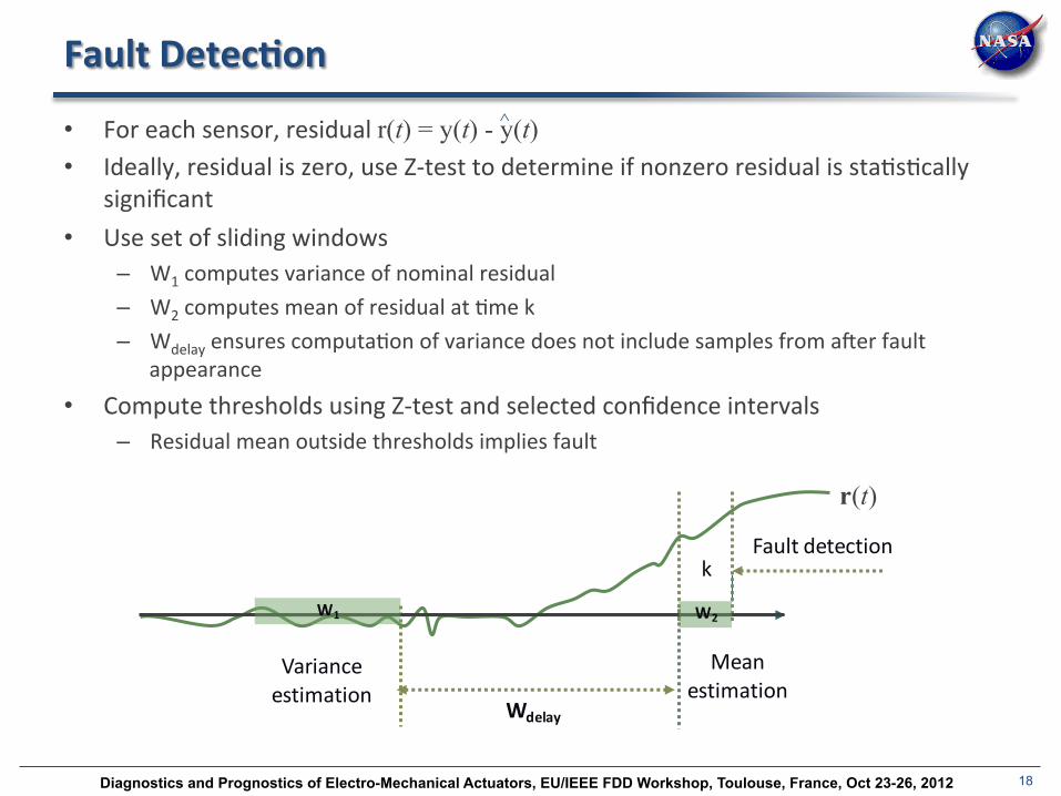
Fault Detec(on
• For each sensor, residual r(t) = y(t) - y(t) • Ideally, residual is zero, use Z-‐test to determine if nonzero residual is staFsFcally
significant • Use set of sliding windows
– W1 computes variance of nominal residual – W2 computes mean of residual at Fme k – Wdelay ensures computaFon of variance does not include samples from aYer fault
appearance
• Compute thresholds using Z-‐test and selected confidence intervals – Residual mean outside thresholds implies fault
Variance estimation
Mean estimation
Wdelay
kFault detection
W2W1
r(t)
^

Diagnostics and Prognostics of Electro-Mechanical Actuators, EU/IEEE FDD Workshop, Toulouse, France, Oct 23-26, 2012 19
Symbol Genera(on
• QualitaFve approach based on analysis of fault transients • Magnitude and slope deviaFons from nominal behavior abstracted as + (increase),
-‐ (decrease), and 0 (no change) symbols • Symbols generated using a sliding-‐window scheme similar to the Z-‐test • Fault signatures are predicFons of how the magnitude and slope of a
measurement will deviate from nominal under each fault case • Represented using symbol pair for measurement and slope • Fault isolaFon performed by comparing observed measurement deviaFons to
predicted deviaFons

Diagnostics and Prognostics of Electro-Mechanical Actuators, EU/IEEE FDD Workshop, Toulouse, France, Oct 23-26, 2012 20
Data-‐Driven Fault Disambigua(on
• AYer an ambiguity set is obtained, the data-‐driven disambiguaFon module is
triggered
• De-‐noising is carried out in real-‐Fme and appropriate features are computed
• Accelerometer data condiFoning and de-‐noising is carried out by characterizing
noise levels when actuators are staFonary (e.g. during parts of trapezoidal profiles)
• Noise characterizaFon consFtutes determinaFon of bias and noise variance
20
0 5 10 15 20 25 30-8
-6
-4
-2
0
2
4
6
8
time (sec)
Acc
ele
ratio
n (
g)
Effect of Denoising
De-Noised SignalOriginal Signal
Effect of De-noising on a sinusoidal profile for a nominal EMA

Diagnostics and Prognostics of Electro-Mechanical Actuators, EU/IEEE FDD Workshop, Toulouse, France, Oct 23-26, 2012 21
High Speed Data Feature Extrac(on • Average Signal Energy (ASE) used as the feature to disFnguish between jam and spall faults
• The feature separates the jam and the spall faults well
– Spall faults are significantly higher in energy than the corresponding nominal scenarios
– Jammed actuator does not move easily, hence has lower vibraFon energy
• Depending on the moFon profile and load levels the energy varies (inherently) between different operaFonal profiles
• Features are normalized by a measure of this inherent energy
• Fault disambiguaFon success rate was ~90% (100% for spalls and 80% for jam faults)
• Due to noise some low energy jammed scenarios were not diagnosed
0 10 20 30 40 50 60-20
-15
-10
-5
0
5
10
15
20
time (seconds)
Vibr
atio
n le
vel (
g)
Differences in Energy Levels from Nominal to Spalled EMA
Nominal EMASpalled EMA
sine sine sine sine trap trap trap trap trap triang triang triang triang triangsweep0
50
100
150
200
250
300
350
400
Load Profiles
Ener
gy M
easu
re
Accelerometer Energy Feature
Nominalspall

Diagnostics and Prognostics of Electro-Mechanical Actuators, EU/IEEE FDD Workshop, Toulouse, France, Oct 23-26, 2012 22
Laboratory Experiments • Faults introduced
– Actuator ball return channel jam (discrete, abrupt) – Lead screw spall (conFnuous, incipient) – Motor failure (discrete, abrupt) – Sensor dead (discrete, abrupt) – Sensor bias & scaling (conFnuous, abrupt) – Sensor driY (conFnuous, incipient)
• Profiles – UH-‐60 Forward Primary Servo (collected in flight) – Laboratory experiments with a wide variety of moFon and load profiles
• Total experiments = 320 – Nominal = 134 – Jam = 15 – Spall = 15 – Motor failure = 15 – Sensor faults= 141
22
1 2 3 4

Diagnostics and Prognostics of Electro-Mechanical Actuators, EU/IEEE FDD Workshop, Toulouse, France, Oct 23-26, 2012 23
Results – Diagnosis Accuracy
23
Fault Type
Total Scenarios
Correct Diagnosis
Diagnosis Accuracy
Nominal 134 133 99.25 Current Sensor Biased 15 15 100.00 Current Sensor Dead 15 15 100.00 Current Sensor Drift 15 15 100.00 Position Sensor Fault 21 13 61.90 Current Sensor Scaling 15 15 100.00 Ball Screw Return Channel Jam 15 10 66.67 Motor Failure 15 15 100.00 Lead Screw Spall 15 15 100.00 Temperature Sensor Bias 15 15 100.00 Temperature Sensor Dead 15 15 100.00 Temperature Sensor Drift 15 15 100.00 Temperature Sensor Scaling 15 15 100.00 Total 320 306 95.625
Diagnostics and Prognostics of Electro-Mechanical Actuators, EU/IEEE FDD Workshop, Toulouse, France, Oct 23-26, 2012 24
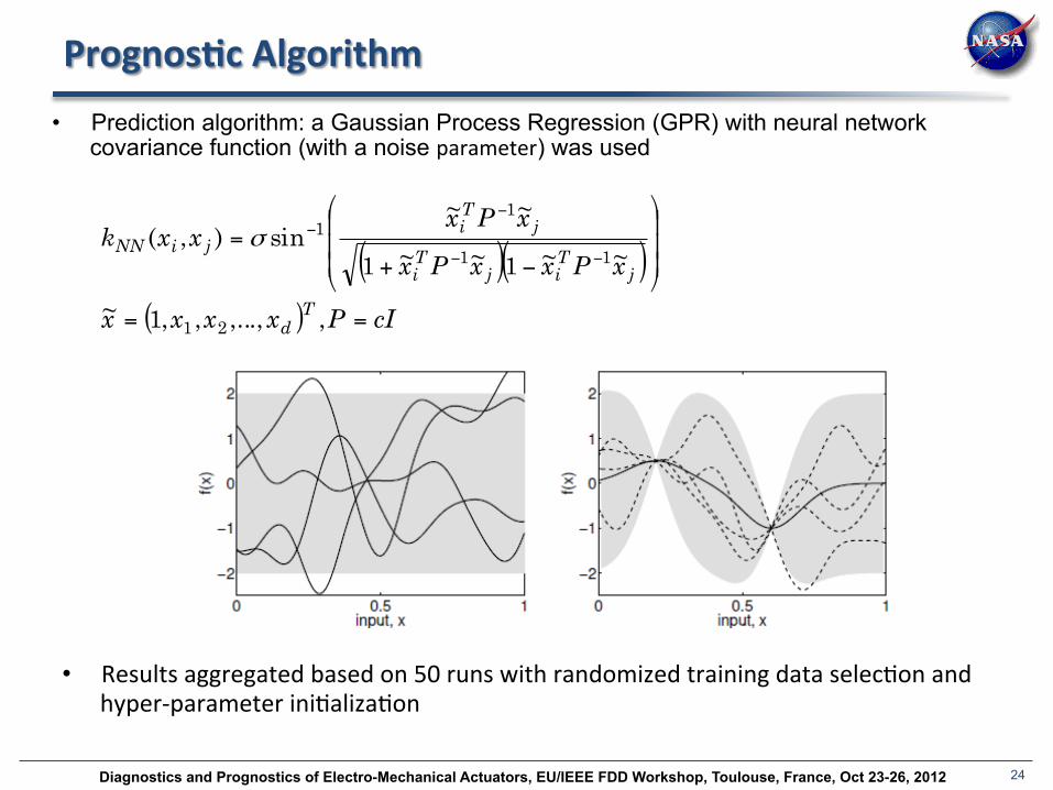
Prognos(c Algorithm • Prediction algorithm: a Gaussian Process Regression (GPR) with neural network
covariance function (with a noise parameter) was used
( )( )( ) cIPxxxx
xPxxPx
xPxxxk
Td
jTij
Ti
jTi
jiNN
==
⎟⎟⎟
⎠
⎞
⎜⎜⎜
⎝
⎛
−+=
−−
−−
,,...,,,1~
~~1~~1
~~sin),(
21
11
11σ
• Results aggregated based on 50 runs with randomized training data selecFon and hyper-‐parameter iniFalizaFon

Diagnostics and Prognostics of Electro-Mechanical Actuators, EU/IEEE FDD Workshop, Toulouse, France, Oct 23-26, 2012 25
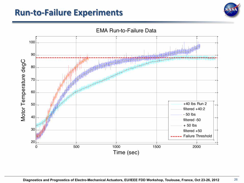
Prognos(c Valida(on Scenario
1. Jam was injected into the ball screw return channel of a test actuator on the FLEA
2. Performance region picked where a nominal actuator can operate conFnuously for extended periods of Fme (100% duty cycle)
3. MoFon and load profiles were designed to stay inside this region – sine wave with 8 cm (3.15 in) peak-‐to-‐peak amplitude, 0.5 Hz frequency, and the following load levels: -‐50, +40, and +50 lbs
4. MoFon was performed in 30 second intervals, with 15 second cool-‐down periods in-‐between
5. Current was limited to 6 amps @ 28 volt for the enFre system at all Fmes
6. Experiments were executed unFl actuator motors failed due to temperature build up and consequent windings insulaFon failure
7. Failure occurs at approximately 88 degrees C
Desired performance region
Ball return jam (abrupt fault)
Heat build-‐up due to increased fric(on (cascading con(nuous fault)
Actuator failure due to motor windings short
Jam mechanism
Diagnostics and Prognostics of Electro-Mechanical Actuators, EU/IEEE FDD Workshop, Toulouse, France, Oct 23-26, 2012 26
Run-‐to-‐Failure Experiments
0 500 1000 1500 200020
30
40
50
60
70
80
90
100
EMA Run-to-Failure Data
Time (sec)
Mot
or T
empe
ratu
re d
egC
+40 lbs Run 2filtered +40:2- 50 lbsfiltered -50+ 50 lbsfiltered +50Failure Threshold
Diagnostics and Prognostics of Electro-Mechanical Actuators, EU/IEEE FDD Workshop, Toulouse, France, Oct 23-26, 2012 27
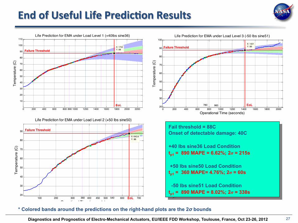
End of Useful Life Predic(on Results
0 200 400 600 800 1000 1200 1400 1600 1800 2000 2200
10
20
30
40
50
60
70
80
90
100
110
X: 1752Y: 88
Operational Time (seconds)
Tem
pera
ture
(C)
Life Prediction for EMA under Load Level 1 (+40lbs sine36)
Failure Threshold
EoL890
100 200 300 400 500 600 70020
30
40
50
60
70
80
90
Operational Time (seconds)
Tem
pera
ture
(C)
Life Prediction for EMA under Load Level 2 (+50 lbs sine50)
X: 642.8Y: 88
Failure Threshold
EoL450 540360
0 200 400 600 800 1000 1200 1400 1600 1800 200020
30
40
50
60
70
80
90
100X: 1421Y: 88
Operational Time (seconds)
Tem
pera
ture
(C)
Life Prediction for EMA under Load Level 3 (-50 lbs sine51)
Failure Threshold
EoL960780
Fail threshold = 88C Onset of detectable damage: 40C +40 lbs sine36 Load Condition tp1 = 890 MAPE = 6.62%; 2σ = 215s +50 lbs sine50 Load Condition tp1 = 360 MAPE= 4.76%; 2σ = 60s -50 lbs sine51 Load Condition tp1 = 890 MAPE = 8.02%; 2σ = 338s
* Colored bands around the predictions on the right-hand plots are the 2σ bounds
Diagnostics and Prognostics of Electro-Mechanical Actuators, EU/IEEE FDD Workshop, Toulouse, France, Oct 23-26, 2012 28
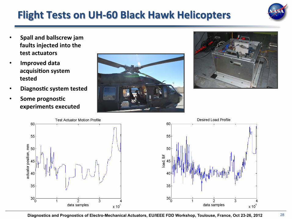
Flight Tests on UH-‐60 Black Hawk Helicopters
• Spall and ballscrew jam faults injected into the test actuators
• Improved data acquisi(on system tested
• Diagnos(c system tested • Some prognos(c
experiments executed
Diagnostics and Prognostics of Electro-Mechanical Actuators, EU/IEEE FDD Workshop, Toulouse, France, Oct 23-26, 2012 29
Recent progress
• DiagnosFc and prognosFc algorithm improvements
• Hardware improvements:
– New accelerometer signal condiFoner
– Winding shorts simulator
– Robustness improvements
• Sensor fault experiments
– PosiFon sensors (stuck)
– Temperature sensors (bias, scaling, driY)
– Current sensors (bias, scaling, driY)
– Hundreds of fault scenarios with different parameters performed

Diagnostics and Prognostics of Electro-Mechanical Actuators, EU/IEEE FDD Workshop, Toulouse, France, Oct 23-26, 2012 30
Summary
• Hardware testbeds, for both laboratory and flight environment, have been developed
• Prototypes of a hybrid diagnosFc system and a GPR-‐based prognosFc system created
• Various types of fault modes injected, both in soYware and hardware
• Tests performed to validate performance in nominal and fault-‐injected scenarios
• Experimental data is available on NASA Ames DASHLink website:
hPps://c3.ndc.nasa.gov/dashlink/
30

Diagnostics and Prognostics of Electro-Mechanical Actuators, EU/IEEE FDD Workshop, Toulouse, France, Oct 23-26, 2012 31
Thank you!