diagnosing 2 sensor heater circuit failures - motor · popular type of connector appear- ... 2...
TRANSCRIPT

32 July 2016
DIAGNOSING O2 SENSOR HEATER CIRCUIT FAILURES
o2heater.indd 1 6/16/16 4:27 PM

As vehicles grow old-er, there comes a point when the ox-ygen or air/fuel ra-tio sensor’s heater circuit will probably
fail. When that happens, the eas-iest fix is to install a new sensor. But when the vehicle comes back two days later with the same heater code, what then?
A local shop called me in on just such a case. The vehicle had come from another shop, which had already replaced the oxygen sensor. The shop that called me also replaced the O2 sensor. Ob-viously, replacing the sensor was not the proper fix. The vehicle had repeatedly returned with a code of P0031—O2 sensor B1S1 low current flow heater circuit failure (open circuit).
From this point on I’ll refer to both oxygen sensors air/fuel ratio sensors as O2 sensors only. I know they aren’t the same thing, but in this case we’re concerned only with the heaters inside both sensor types. And in that respect, they’re fundamentally the same.
One popular test is to check the amperage of the O2 sensor’s heater circuit. This test confirms that the O2 sensor’s heater itself is work-ing and would lead you to believe that the vehicle is fixed. But what caused the vehicle to return two days later with the same code? One possibility is that the sensor’s heat-er circuit may be coming on at the wrong time.
Let’s think about this. Do we need the O2 sensor’s heater cir-cuit coming on when the engine is not running? Not likely. We need to keep in mind that the ECM is controlling the operation of the heater circuit. Also, an amp meter can’t really help locate the source of the problem; it can indicate on-ly that the problem is present at that moment.
Whenever I diagnose electrical
33July 2016
BY TOM TILLMAN
Oxygen sensor heaters do fail. But there are other possible causes for a heater DTC. Before screwing in a new sensor, this simple test will determine whether everything else is in order.
Pho
to: T
hin
ksto
ck
o2heater.indd 2 6/16/16 4:28 PM
34 July 2016
problems, I like to develop a quick and simple way of testing the cir-cuits, if possible. When testing the O2 sensor’s heater circuit, I found using a #7440 incandescent light bulb and socket very helpful. You connect the l ight to the vehi-cle’s O2 sensor heater harness in place of the sensor. The light bulb draws about 1.75A at 12V. This is usually within the operating range of the sensor’s heater. This works very well—about 95% of the time.
When you replace a bad O 2
sensor, cut the sensor off the old harness. Using the old harness wi l l help e l iminate the poss i -bility of tapping into the wrong circuit, a potentially costly mis-take. Now connect a female spade connector to each heater wire of the harness. Usually the heater wires on the sensor’s harness are both either black or white. Next, connect the #7440 bulb and light socket to the harness.
At this point, the four-wire plug configuration seems to be the most popular type of connector appear-ing in aftermarket shops. Howev-er, oxygen sensors can have five or more wires. These sensors will still have two dedicated heater wires.
Once you match the plug and wiring configuration to the vehi-cle’s O2 sensor connector, you’re ready to start testing. First, re-cord the computer codes, includ-ing freeze frame information. Re-member, the freeze frame infor-mation shows the driving condi-tions at the point when the code set. Then clear the codes. Some computer systems will shut the O2 heater circuit off until the codes are cleared.
Now, with the ignition switch off, plug the test harness with the light into the vehicle’s O2 sensor har-ness connection. The light should remain off until the engine is start-ed. Once the engine is running,
Diagnosing O2 Sensor Heater Circuit Failures
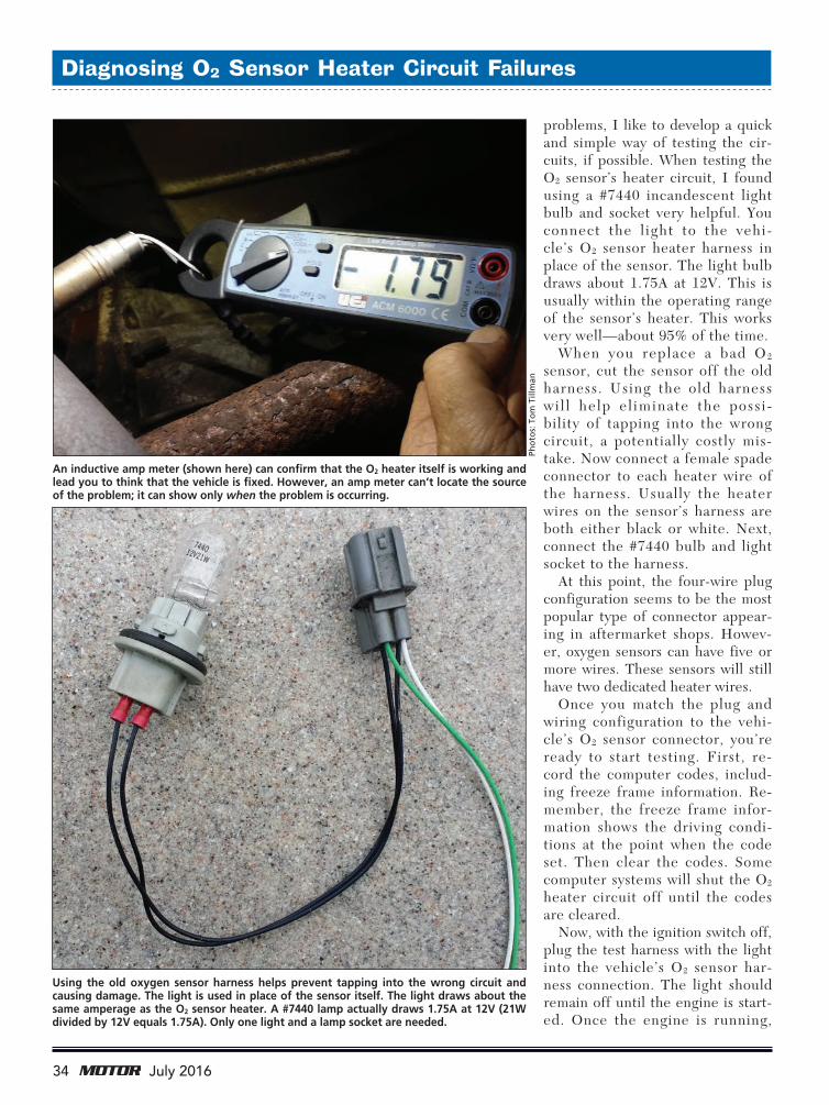
Using the old oxygen sensor harness helps prevent tapping into the wrong circuit and causing damage. The light is used in place of the sensor itself. The light draws about the same amperage as the O2 sensor heater. A #7440 lamp actually draws 1.75A at 12V (21W divided by 12V equals 1.75A). Only one light and a lamp socket are needed.
An inductive amp meter (shown here) can confirm that the O2 heater itself is working and lead you to think that the vehicle is fixed. However, an amp meter can’t locate the source of the problem; it can show only when the problem is occurring.
Pho
tos:
To
m T
illm
an
o2heater.indd 3 6/16/16 4:28 PM
36 July 2016
Diagnosing O2 Sensor Heater Circuit Failures
er circuit. You should refer to the vehicle’s wiring schematic for how that circuit is wired.
The O2 sensor’s heater circuit is controlled in one of two ways. First is the positively controlled type of circuit. If the O2 sensor heater cir-cuit’s negative wire goes directly to ground, look for a short-to-power problem. Usually the heater cir-
cuit in this case is controlled by a relay. Remove the relay and retest the circuit. If the light comes on again, locate the short-to-voltage in the wiring harness with the relay removed. Trace the harness from the O2 sensor’s connection back to the relay. When you’re close to the source of the problem, the light may flicker or go off.
the light should come on steady or blink. This is considered normal circuit operation. As a safety pre-caution, perform this test for 30 seconds or less. The computer may possibly reset the code.
If the light comes on with the ignition switch off or when the key only is turned on (engine off), then there’s a problem with the heat-
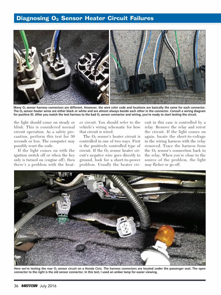
Here we’re testing the rear O2 sensor circuit on a Honda Civic. The harness connectors are located under the passenger seat. The open connector to the right is the old sensor connector. In this test, I used an amber lamp for easier viewing.
Many O2 sensor harness connectors are different. However, the wire color code and locations are basically the same for each connector. The O2 sensor heater wires are either black or white and are almost always beside each other in the connector. Consult a wiring diagram for positive ID. After you match the test harness to the bad O2 sensor connector and wiring, you’re ready to start testing the circuit.
o2heater.indd 4 6/16/16 4:28 PM

37July 2016
Diagnosing O2 Sensor Heater Circuit Failures
There are times when the light will go out instantly once the relay is removed. The relay itself may be shorted or the relay control circuit may have a problem. Either way, you need to locate the source of the problem.
Now let’s cover the O2 sensor’s negatively controlled heater circuit. If the wiring schematic shows the O2 sensor heater circuit is ground controlled through the computer, start looking for a short-to-ground on the sensor’s negative control wire. One quick test is to discon-nect the computer from the circuit. Make sure you have the ignition switch off and the battery discon-nected first. Then reconnect the battery and turn the ignition switch back on. If the wire from the O2
heater connector to the computer is shorted to ground, the light will
VT56 OBDII TPMs Diagnostic Tool
USER FRIENDLY INTUITIVE FAST
ateqtpm.com(English) 1-734-838-3100(Español) 1-210-451-1074
MAIN MENU - CHECK TPMS SERVICE TPMS COPY OR CREATE SENSORSPrograms Aftermarket Sensors
Copies OEM Sensors
DISPLAY SENSOR DATA
READ COPY OR CREATESERVICECHECK
FUNCTIONALITY
• Programs AAermarket Universal Sensors • Tests Remote Keyless Entry • Unlocks ECU Loop Issue on Toyota Family Vehicle
• Resets Tire Pressure Monitoring Systems (TPMS) • Reads and Accvates Tire Pressure Sensors Directly from Tires • The ONLY TPMS Tool with VIN Scan to Select Vehicle MMY
RESETS VEHICLE TPM SYSTEMOE & AFTERMARKET SENSOR COMPATIBILITY
Circle #15
Left: Here the test harness is connected to the O2 sensor harness connector on a Subaru Outback. The light should remain off until the engine is running. Again, the amber lamp was used for clearer viewing. Right: When the engine is running, the light will come on or blink. This is considered normal oxygen sensor heater circuit operation.
o2heater.indd 5 6/16/16 4:29 PM

38 July 2016
still be on. Trace the wiring harness back to the computer while mon-itoring the light. When you locate the area of the short, the light may again flicker or go off.
In the case I was called in on, the vehicle was a 2000 Jeep Grand Cherokee with the 4.0L engine. The vehicle’s O2 sensor harness was pinched underneath the valve cover at the back of the cylinder head. Fortunately, the sensor’s negative heater wire was the only wire in the harness that was involved. The valve cover gasket had recently been replaced.
One of the technicians brought up an interesting question: With the control wire being shorted to ground, why did the computer set a code for an open heater circuit?
The computer is looking for 12V on the sensor’s negative control wire while the computer’s O2 sen-sor heater circuit driver (the power transistor in the computer) is open. With the wire being grounded, the O2 sensor heater circuit came on as soon as the ignition switch was turned on. The computer control was bypassed at that point. There-fore, the computer’s monitored voltage was zero while the circuit driver was still open. The computer is programmed to set a code for an open heater circuit at this point. Again, this is where the amp meter reading would lead you to think the circuit is operating fine.
There will also be times when the light will remain off with the engine running. In that case, first check for a blown fuse. If the O2 sensor’s heater had shorted out, the fuse may have blown as well.
Once you determine that the fuse is okay, check for voltage at the O2 sensor harness connection. The modified test harness with the light will give you easy access to the circuit. Remember, the en-gine needs to be running at this
Diagnosing O2 Sensor Heater Circuit Failures
There will be times when the test harness doesn’t work. In those cases, use a new O2
sensor and monitor the voltage on the negative wire of the sensor. A lab scope will show 12V with the key on, engine off. The voltage on the negative wire should drop to zero or pulse when the engine is running. A voltmeter can be used here; however, the meter reading will never reach zero if the voltage is pulsing. Remember, a DVOM averages the voltage that’s being measured.
o2heater.indd 6 6/16/16 4:29 PM

This article can be found online at www.motormagazine.com.
point. If the voltage is close to zero on the positive heater wire, then locate the open circuit in the power wire back to the fuse. Again, i t may have a relay in the circuit as well. However, if the O2
sensor harness volt-age shows bat tery voltage on both heat-er wires (with the l ight sti l l connect-ed), locate the pos-sible open circuit in the sensor’s negative wire. Also be sure to check all comput-er grounds. There’s a possibility that the computer may have a dedicated ground for this circuit. The worst-case scenario at this point would be
a blown computer driver.As I pointed out earlier, this
procedure works about 95% of
the time. One of the vehicles it didn’t work with was a 1997 Toy-ota 4Runner with the V6 engine.
In this case there was voltage on both wires to the O2 sensor heat-er circuit. Most computer systems
will also monitor the current flow to the sensor. The light’s current draw was not within the op-erating range of this system’s heater cir-cuit. Therefore, the computer shut the circuit off to protect the system (particu-larly protecting the computer ’s c ircuit drivers).
In situations like this, plug a new sen-sor into the harness
only. I recommend using a new sen-sor here. There are times when the old sensor will initially work, then quit once the sensor gets hot. That actually could be the problem. This test can be performed without the need to install the new sensor into the exhaust pipe or manifold.
Now monitor the voltage on the sensor’s negative heater wire. When the vehicle is started, 12V should be present momentarily. Then the voltage will drop to zero or pulse. When using a lab scope, the pulse will increase in on time, dropping to zero as the heater stays on longer. A DVOM could be used for this test, but keep in mind that the voltmeter is only averaging the reading. That could be confusing.
Whenever you replace an oxy-gen sensor due to a heater code, always check the circuit operation. The test harness with the light makes checking the circuit quick and easy. This will help eliminate comebacks and save the shop and you precious time.
40 July 2016
Mueller-Kueps LP
5126 South Royal Atlanta DriveTucker GA 30084
Phone: +1 770 349- 6331www.mueller-kueps.com
5-piece Clip Lifter Set
Ask your local tool truck or distributor
A high quality, professional set of 5 clip lifters. Each clip lifter is shaped to enable the user to reach into tight areas and easily remove a variety of retaining vehicle clip types. With this new kit, there is no clip out of reach!
#277 015 5-piece Clip Lifter Kit
Circle #17
Diagnosing O2 Sensor Heater Circuit Failures
Here’s an interesting question: With the control wire being
shorted to ground, why did the computer set a code for an
open heater circuit?
o2heater.indd 7 6/16/16 4:29 PM