diamond da 40 & da 40 fdiamondaviators.net/downloads/maintenancemanuals/g1000 da40 fiel… ·...
TRANSCRIPT
190-00544-01 September, 2005 Revision A
G1000 Field Update Instructions
Diamond DA 40 & DA 40 F FAA STC #SA01254WI
Amendment 2 (Includes ADF, DME, GDL 69 Upgrade)
Page A G1000 Field Update Instructions - Diamond DA 40 Revision A 190-00544-01
© Copyright 2005 Garmin Ltd. or its subsidiaries
All Rights Reserved Except as expressly provided herein, no part of this manual may be reproduced, copied, transmitted, disseminated, downloaded or stored in any storage medium, for any purpose without the express prior written consent of Garmin. Garmin hereby grants permission to download a single copy of this manual and of any revision to this manual onto a hard drive or other electronic storage medium to be viewed and to print one copy of this manual or of any revision hereto, provided that such electronic or printed copy of this manual or revision must contain the complete text of this copyright notice and provided further that any unauthorized commercial distribution of this manual or any revision hereto is strictly prohibited.
Garmin International, Inc. 1200 E. 151st Street
Olathe, KS 66062 USA Telephone: 913-397-8200
www.garmin.com
Garmin (Europe) Ltd. Unit 5, The Quadrangle
Abbey Park Industrial Estate Romsey, SO51 9DL U.K.
Telephone: 44/0870.8501241
RECORD OF REVISIONS
Revision Revision Date Description ECO #A 9/02/2005 Initial release for STC Amendment 1 -------
DOCUMENT PAGINATION
Section Pagination Table of Contents
i – iv
Section 1 1-1 – 1-4 Section 2 2-1 – 2-10 Section 3 3-1 – 3-8 Section 4 4-1 – 4-10
G1000 Field Update Instructions - Diamond DA 40 Page i 190-00544-01 Revision A
INFORMATION SUBJECT TO EXPORT CONTROL LAWS
This document may contain information which is subject to the Export Administration Regulations ("EAR") issued by the United States Department of Commerce (15 CFR, Chapter VII, Subchapter C) and which may not be exported, released, or disclosed to foreign nationals inside or outside of the United States without first obtaining an export license. A violation of the EAR may be subject to a penalty of up to 10 years imprisonment and a fine of up to $1,000,000 under Section 2410 of the Export Administration Act of 1979. Include this notice with any reproduced portion of this document.
This product, its packaging, and its components contain chemicals known to the State of California to cause cancer, birth defects, or reproductive harm. This Notice is being provided in accordance with California's Proposition 65. If you have any questions or would like additional information, please refer to our web site at www.garmin.com/prop65.
The GDU 1040s use a lens coated with a special anti-reflective coating that is very sensitive to skin oils, waxes and abrasive cleaners. CLEANERS CONTAINING AMMONIA WILL HARM THE ANTI-REFLECTIVE COATING. It is very important to clean the lens using a clean, lint-free cloth and an eyeglass lens cleaner that is specified as safe for anti-reflective coatings
All G1000 screen shots used in this document are current at the time of initial publication. Screen shots are intended to provide visual reference only. All information depicted in screen shots, including software file names, versions and part numbers, is subject to change and may not be up to date.
All references to Diamond DA 40 aircraft made in this manual equally apply to Diamond DA 40 F aircraft, unless otherwise noted.
CAUTION
WARNING
IMPORTANT
IMPORTANT
Page ii G1000 Field Update Instructions - Diamond DA 40 Revision A 190-00544-01
This page intentionally left blank
G1000 Field Update Instructions - Diamond DA 40 Page iii 190-00544-01 Revision A
TABLE OF CONTENTS PARAGRAPH PAGE
1 INTRODUCTION 1-1 1.1 Scope..................................................................................................................................................1-1 1.2 Aircraft Eligibility..............................................................................................................................1-1 1.3 Upgrade Preparation Requirements ...................................................................................................1-3 1.4 Required Equipment: .........................................................................................................................1-3 1.5 Additional Documents .......................................................................................................................1-4 2 G1000 Software Loading 2-1 2.1 System Power Up...............................................................................................................................2-1 2.2 MFD & PFD Software Load ..............................................................................................................2-1 2.3 GIA Software Load ............................................................................................................................2-2 2.4 GMA 1347 Audio Panel Software .....................................................................................................2-4 2.5 GDC 74A Air Data Computer Software ............................................................................................2-5 2.6 GRS 77 AHRS Software....................................................................................................................2-6 2.7 GMU 44 Magnetometer Software......................................................................................................2-7 2.8 GTX 33 Transponder Software ..........................................................................................................2-8 2.9 GEA 71 Engine/Airframe Unit Software ...........................................................................................2-9 3 Configuration File Upgrade 3-1 3.1 Optional Equipment Configuration....................................................................................................3-2 4 Return to Service 4-1 4.1 Software Load Confirmation..............................................................................................................4-1 4.2 TESTING PROCEDURE ..................................................................................................................4-2 4.3 ADF Checkout ...................................................................................................................................4-4 4.4 DME Checkout ..................................................................................................................................4-5 4.5 GDL 69 Checkout ..............................................................................................................................4-6 4.6 Aviation Database Loading (Optional) ..............................................................................................4-7 4.7 New Terrain Database Card Installation (Optional) ..........................................................................4-8 4.8 VNAV Placard Removal....................................................................................................................4-9 4.9 Aircraft Record Entry.......................................................................................................................4-10
LIST OF TABLES TABLE PAGE TABLE 1-1. STC SA01254WI CONFIGURATIONS.............................................................................1-1 TABLE 1-2. REFERENCED DOCUMENTATION................................................................................1-4 TABLE 1-3. OPERATING DOCUMENTATION...................................................................................1-4
Page iv G1000 Field Update Instructions - Diamond DA 40 Revision A 190-00544-01
This page intentionally left blank.
G1000 Field Upgrade Instructions - Diamond DA 40 Page 1-1 190-00544-01 Revision A
1 INTRODUCTION
1.1 Scope
This document presents field upgrade procedures for G1000-equipped Diamond Model DA40 and DA40 F aircraft.
This document sets forth instructions to be followed in order to upgrade an existing approved configuration of the STC to a newer approved configuration.
It is assumed that the person performing the upgrade is familiar with the aircraft and has a working knowledge of typical avionics systems.
Instructions contained in this document are written for specifically for G1000 upgrades and are not suitable for new G1000 installations. Refer to the G1000/DA40 Post Installation Checkout Procedure, 190-00544-00, for new installation checkout instructions.
1.2 Aircraft Eligibility
Eligible aircraft are equipped with FAA STC SA01254WI, which approved the installation of the Garmin G1000 Integrated Cockpit System. There are three approved configurations of this STC. Configurations are governed primarily by the G1000 System Software Version number. The System Software Version is a derivative of the G1000/DA40 Software Loader Card part number.
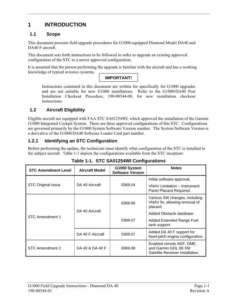
1.2.1 Identifying an STC Configuration
Before performing the update, the technician must identify what configuration of the STC is installed in the subject aircraft. Table 1-1 depicts the configurations available from the STC inception:
Table 1-1. STC SA01254WI Configurations
STC Amendment Level Aircraft Model G1000 System Software Version
Notes
STC Original Issue DA 40 Aircraft 0369.04
Initial software approval.
VNAV Limitation – Instrument Panel Placard Required.
0369.06
DA 40 Aircraft
0369.07
Various SW changes, including VNAV fix, allowing removal of placard.
Added Obstacle database.
Added Extended Range Fuel tank support.
STC Amendment 1
DA 40 F Aircraft 0369.07 Added DA 40 F support for fixed-pitch engine configuration.
STC Amendment 2 DA 40 & DA 40 F 0369.08 Enabled remote ADF, DME, and Garmin GDL 69 XM Satellite Receiver installation.
IMPORTANT!
Page 1-2 G1000 Field Upgrade Instructions - Diamond DA 40 Revision A 190-00544-01
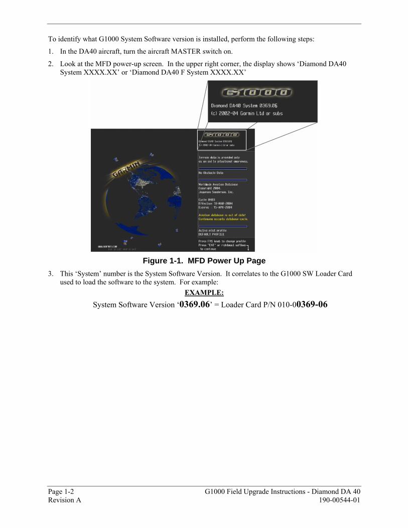
To identify what G1000 System Software version is installed, perform the following steps:
1. In the DA40 aircraft, turn the aircraft MASTER switch on.
2. Look at the MFD power-up screen. In the upper right corner, the display shows �Diamond DA40 System XXXX.XX� or �Diamond DA40 F System XXXX.XX�
Figure 1-1. MFD Power Up Page
3. This �System� number is the System Software Version. It correlates to the G1000 SW Loader Card used to load the software to the system. For example:
EXAMPLE:
System Software Version �0369.06� = Loader Card P/N 010-00369-06
G1000 Field Upgrade Instructions - Diamond DA 40 Page 1-3 190-00544-01 Revision A
1.3 Upgrade Preparation Requirements
The technician must first do the following:
! Identify the currently installed STC configuration of the subject aircraft. Know what System Software Version is installed in the subject aircraft. Refer to Section 1.2.1. Record the currently installed System Software Version here: _____________________
! Ensure that the installation of the G1000 has not been altered from the installed STC configuration. Ensure that the system operates properly before starting the update by making sure no red X�s or other system problems exist.
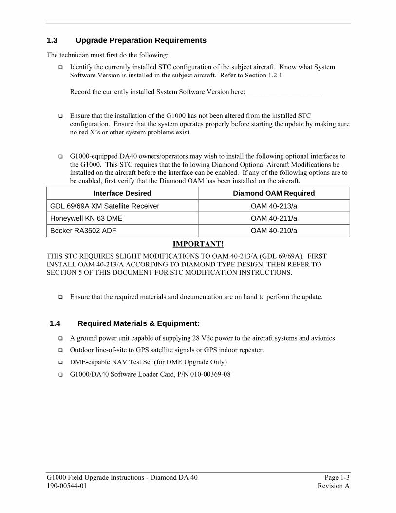
! G1000-equipped DA40 owners/operators may wish to install the following optional interfaces to the G1000. This STC requires that the following Diamond Optional Aircraft Modifications be installed on the aircraft before the interface can be enabled. If any of the following options are to be enabled, first verify that the Diamond OAM has been installed on the aircraft.
Interface Desired Diamond OAM Required
GDL 69/69A XM Satellite Receiver OAM 40-213/a
Honeywell KN 63 DME OAM 40-211/a
Becker RA3502 ADF OAM 40-210/a
IMPORTANT! THIS STC REQUIRES SLIGHT MODIFICATIONS TO OAM 40-213/A (GDL 69/69A). FIRST INSTALL OAM 40-213/A ACCORDING TO DIAMOND TYPE DESIGN, THEN REFER TO SECTION 5 OF THIS DOCUMENT FOR STC MODIFICATION INSTRUCTIONS.
! Ensure that the required materials and documentation are on hand to perform the update.
1.4 Required Materials & Equipment:
! A ground power unit capable of supplying 28 Vdc power to the aircraft systems and avionics.
! Outdoor line-of-site to GPS satellite signals or GPS indoor repeater.
! DME-capable NAV Test Set (for DME Upgrade Only)
! G1000/DA40 Software Loader Card, P/N 010-00369-08

Page 1-4 G1000 Field Upgrade Instructions - Diamond DA 40 Revision A 190-00544-01
1.5 Required Documents
The following documents are required to perform the update.
Table 1-2. Required Documentation
Document Number Document
005-00305-00 Required Equipment List, Garmin G1000, Diamond Model DA 40
190-00355-04* GDL 69/69A XM Satellite Radio Activation Instructions
*Only required for GDL 69/69A Upgrade.
1.5.1 Reference Documentation
The following documents provide additional information relevant to this update:
Table 1-3. Reference Documentation
Document Number Document
005-C0004-00 G1000/DA40 STC Master Drawing List
005-00304-00 G1000/DA40 Install Drawing
001-00029-00 Garmin Installation Standard Practices
1.5.2 Required Operating Documentation
The following documents are required to be presented to the aircraft owner or operator upon completion of the upgrade.
Table 1-4. Operating Documentation
STC Configuration Document Number Document
190-00303-02, Revision 8 G1000/DA40 Airplane Flight Manual Supplement
190-00324-03 G1000/DA40 Cockpit Reference Guide Amendment 2
Upgrade 190-00545-00, Revision B G1000/DA40 System Maintenance Manual (ICA)

G1000 Field Upgrade Instructions - Diamond DA 40 Page 2-1 190-00544-01 Revision A
2 G1000 Software Upgrade Procedure NOTE:
Throughout the next portion of this section, many screen shots and examples are used to illustrate the software and configuration loading process. Although every effort has been made to ensure accuracy of such examples, differences be noted. Refer to the G1000/DA40 Required Equipment List (005-00305-00) for the correct software file names, versions and part numbers.
2.1 System Power Up
Apply power to the G1000 by doing the following
1. Turn on the ground power unit, if utilized.
2. Turn on the BAT side master switch.
3. Turn on the AVIONICS MASTER switch. At this moment, all G1000 equipment is receiving power. For convenience, the technician may opt remove power from the KAP 140, rate and backup-attitude gyros by pulling the circuit breakers labeled �AP�, �HORIZON�, and �RATE GYRO�.
2.2 MFD & PFD Software Load
1. Pull the MFD and PFD circuit breakers.
2. Insert the correct G1000/DA 40 Loader Card into the MFD top card slot.
3. While holding the ENT key on the MFD, restore power by closing the MFD circuit breaker.
4. When the words appear in the upper left corner of the MFD, release the ENT key.
5. Press the ENT key to acknowledge the following prompt (NOTE: A softkey labeled �YES� appears in the lower right corner and may be used in lieu of the ENT key):
6. The following screen is displayed.
7. New software is loaded to the MFD. When complete, the MFD starts in configuration mode.
8. Remove the G1000/DA 40 Loader Card from the MFD and insert it into the top card slot on the PFD. Repeat Steps 3 through 6 for the PFD.
9. When PFD update is complete, it starts in the configuration mode. Do not remove power. IMPORTANT!
For the rest of the software/configuration procedure, do not operate the MFD while loading software or configuration files unless specifically instructed to do so. A failed or cancelled load may result.

Page 2-2 G1000 Field Upgrade Instructions - Diamond DA 40 Revision A 190-00544-01
2.3 GIA Software Load
1. Go to the Software Upload page using the small FMS knob.
2. Activate the cursor and select the GIA software file. Verify that GIA1 and GIA2 appear in the LRU field as shown:
3. Press the LOAD softkey.
4. Select OK and press ENT to acknowledge the following prompt:
5. The software for GIA1 begins to load. GIA2 software loads immediately after GIA1 software
finishes loading. Monitor the upload status as it progresses:
6. After the files finish loading, press ENT to acknowledge the following prompt:
7. View the SUMMARY field and verify that both GIA1 and GIA2 software loading is complete.
G1000 Field Upgrade Instructions - Diamond DA 40 Page 2-3 190-00544-01 Revision A
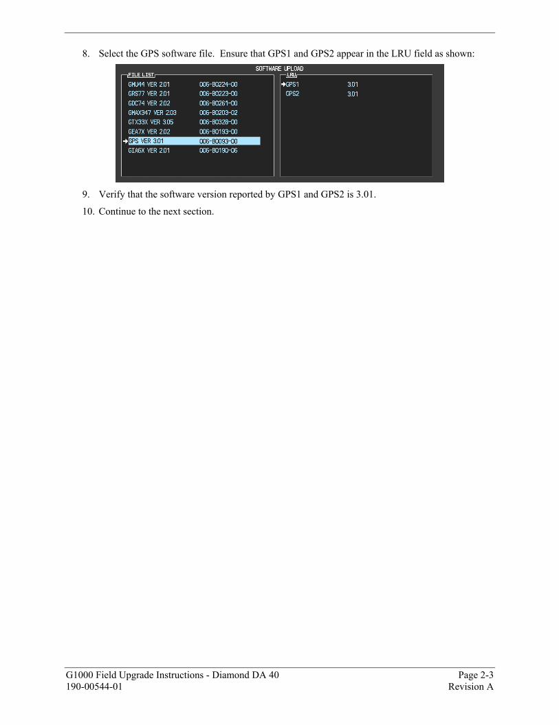
8. Select the GPS software file. Ensure that GPS1 and GPS2 appear in the LRU field as shown:
9. Verify that the software version reported by GPS1 and GPS2 is 3.01.
10. Continue to the next section.

Page 2-4 G1000 Field Upgrade Instructions - Diamond DA 40 Revision A 190-00544-01
2.4 GMA 1347 Audio Panel Software
1. Activate the cursor and highlight the GMA software file. Ensure that both paths to the GMA through GIA1 and GIA 2 appear in the LRU field as shown:
2. Press the LRU softkey. Select the GMA1 - GIA1 data path to load software. Press the LOAD
softkey.
3. Select OK and press the ENT key to acknowledge the following prompt:
4. The software for the GMA 1347 Audio Panel begins to load. Monitor the upload status as it
progresses:
5. After the files finish loading, press ENT to acknowledge the following prompt:
6. Check the SUMMARY field to ensure the load is �COMPLETE�.
G1000 Field Upgrade Instructions - Diamond DA 40 Page 2-5 190-00544-01 Revision A
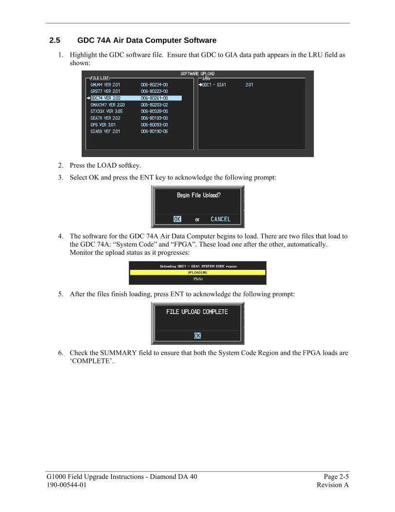
2.5 GDC 74A Air Data Computer Software
1. Highlight the GDC software file. Ensure that GDC to GIA data path appears in the LRU field as shown:
2. Press the LOAD softkey.
3. Select OK and press the ENT key to acknowledge the following prompt:
4. The software for the GDC 74A Air Data Computer begins to load. There are two files that load to
the GDC 74A: �System Code� and �FPGA�. These load one after the other, automatically. Monitor the upload status as it progresses:
5. After the files finish loading, press ENT to acknowledge the following prompt:
6. Check the SUMMARY field to ensure that both the System Code Region and the FPGA loads are
�COMPLETE�.
Page 2-6 G1000 Field Upgrade Instructions - Diamond DA 40 Revision A 190-00544-01
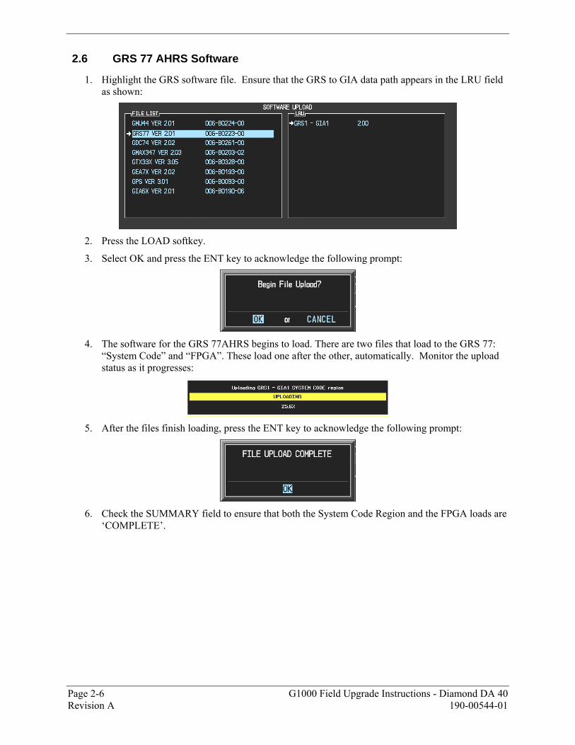
2.6 GRS 77 AHRS Software
1. Highlight the GRS software file. Ensure that the GRS to GIA data path appears in the LRU field as shown:
2. Press the LOAD softkey.
3. Select OK and press the ENT key to acknowledge the following prompt:
4. The software for the GRS 77AHRS begins to load. There are two files that load to the GRS 77:
�System Code� and �FPGA�. These load one after the other, automatically. Monitor the upload status as it progresses:
5. After the files finish loading, press the ENT key to acknowledge the following prompt:
6. Check the SUMMARY field to ensure that both the System Code Region and the FPGA loads are
�COMPLETE�.
G1000 Field Upgrade Instructions - Diamond DA 40 Page 2-7 190-00544-01 Revision A
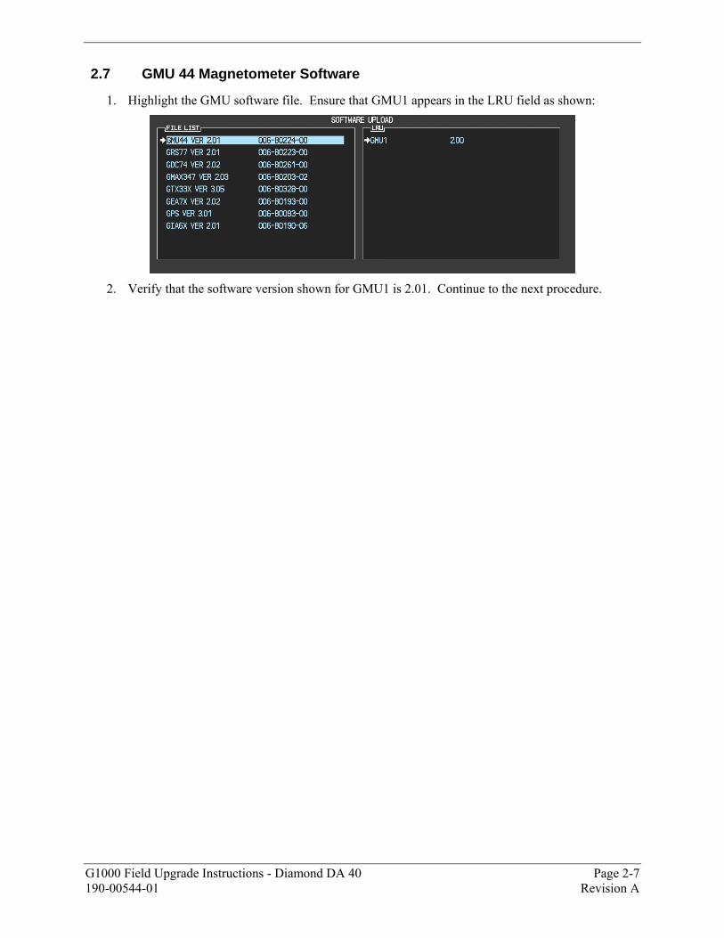
2.7 GMU 44 Magnetometer Software
1. Highlight the GMU software file. Ensure that GMU1 appears in the LRU field as shown:
2. Verify that the software version shown for GMU1 is 2.01. Continue to the next procedure.

Page 2-8 G1000 Field Upgrade Instructions - Diamond DA 40 Revision A 190-00544-01
2.8 GTX 33 Transponder Software
1. Highlight the GTX software file. Ensure that both paths to the GTX 33 through GIA1 and GIA 2 appear in the LRU field as shown:
2. Press the LRU softkey. Select the GTX1 - GIA1 data path to load software. Press the LOAD
softkey.
3. Select OK and press the ENT key to acknowledge the following prompt:
4. The software for the GTX 33 transponder begins to load. Monitor the upload status as it
progresses:
5. After the files finish loading, press ENT to acknowledge the following prompt:
6. Check the SUMMARY field to ensure the load is �COMPLETE�.
G1000 Field Upgrade Instructions - Diamond DA 40 Page 2-9 190-00544-01 Revision A
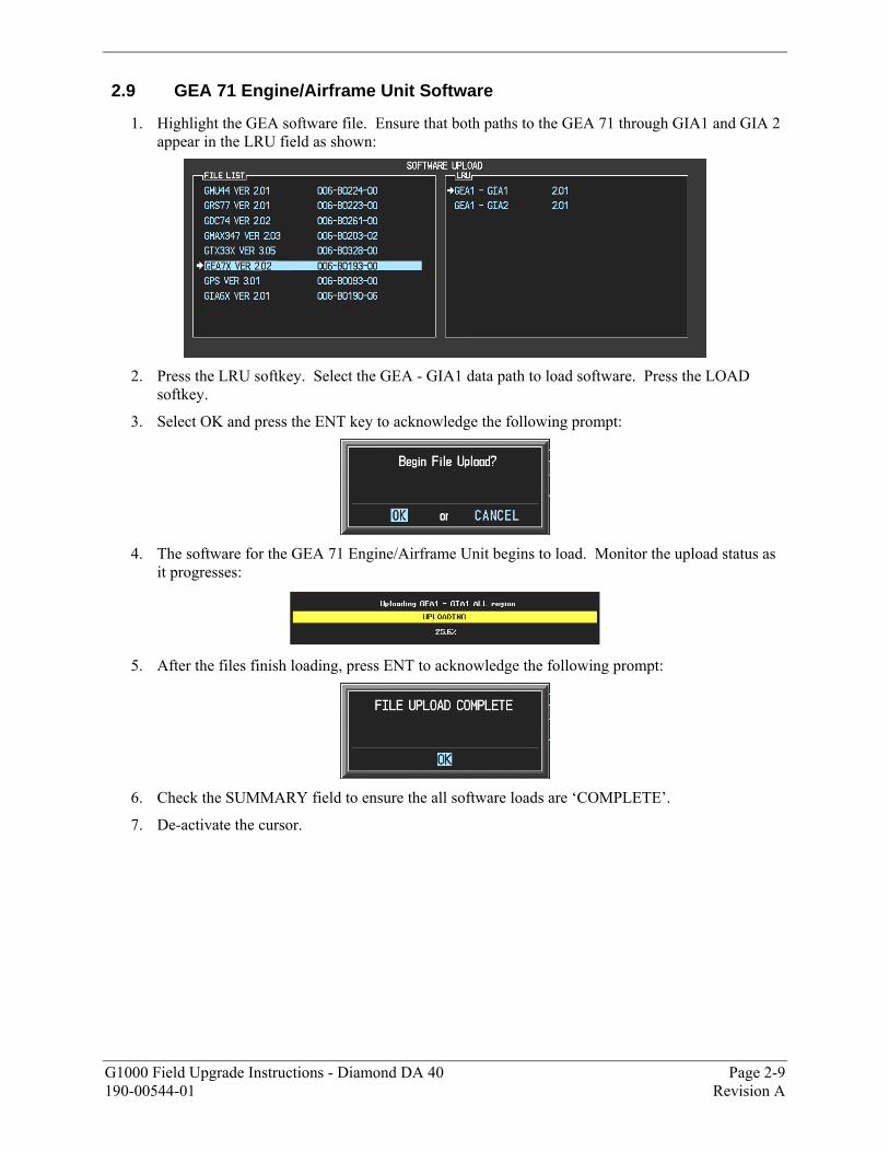
2.9 GEA 71 Engine/Airframe Unit Software
1. Highlight the GEA software file. Ensure that both paths to the GEA 71 through GIA1 and GIA 2 appear in the LRU field as shown:
2. Press the LRU softkey. Select the GEA - GIA1 data path to load software. Press the LOAD
softkey.
3. Select OK and press the ENT key to acknowledge the following prompt:
4. The software for the GEA 71 Engine/Airframe Unit begins to load. Monitor the upload status as
it progresses:
5. After the files finish loading, press ENT to acknowledge the following prompt:
6. Check the SUMMARY field to ensure the all software loads are �COMPLETE�.
7. De-activate the cursor.
Page 2-10 G1000 Field Upgrade Instructions - Diamond DA 40 Revision A 190-00544-01
This page intentionally left blank.
G1000 Field Upgrade Instructions - Diamond DA 40 Page 3-1 190-00544-01 Revision A
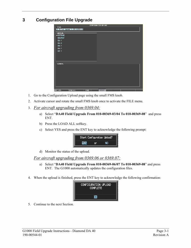
3 Configuration File Upgrade
1. Go to the Configuration Upload page using the small FMS knob.
2. Activate cursor and rotate the small FMS knob once to activate the FILE menu.
3. For aircraft upgrading from 0369.04:
a) Select �DA40 Field Upgrade From 010-00369-03/04 To 010-00369-08� and press ENT.
b) Press the LOAD ALL softkey.
c) Select YES and press the ENT key to acknowledge the following prompt:
d) Monitor the status of the upload.
For aircraft upgrading from 0369.06 or 0369.07:
a) Select �DA40 Field Upgrade From 010-00369-06/07 To 010-00369-08� and press ENT. The G1000 automatically updates the configuration files.
4. When the upload is finished, press the ENT key to acknowledge the following confirmation:
5. Continue to the next Section.
Page 3-2 G1000 Field Upgrade Instructions - Diamond DA 40 Revision A 190-00544-01
3.1 Optional Equipment Configuration
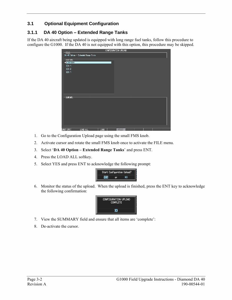
3.1.1 DA 40 Option – Extended Range Tanks
If the DA 40 aircraft being updated is equipped with long range fuel tanks, follow this procedure to configure the G1000. If the DA 40 is not equipped with this option, this procedure may be skipped.
1. Go to the Configuration Upload page using the small FMS knob.
2. Activate cursor and rotate the small FMS knob once to activate the FILE menu.
3. Select �DA 40 Option � Extended Range Tanks� and press ENT.
4. Press the LOAD ALL softkey.
5. Select YES and press ENT to acknowledge the following prompt:
6. Monitor the status of the upload. When the upload is finished, press the ENT key to acknowledge
the following confirmation:
7. View the SUMMARY field and ensure that all items are �complete�:
8. De-activate the cursor.
G1000 Field Upgrade Instructions - Diamond DA 40 Page 3-3 190-00544-01 Revision A
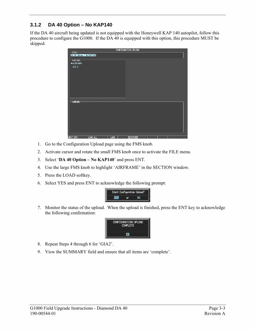
3.1.2 DA 40 Option – No KAP140
If the DA 40 aircraft being updated is not equipped with the Honeywell KAP 140 autopilot, follow this procedure to configure the G1000. If the DA 40 is equipped with this option, this procedure MUST be skipped.
1. Go to the Configuration Upload page using the FMS knob.
2. Activate cursor and rotate the small FMS knob once to activate the FILE menu.
3. Select �DA 40 Option � No KAP140� and press ENT.
4. Use the large FMS knob to highlight �AIRFRAME� in the SECTION window.
5. Press the LOAD softkey.
6. Select YES and press ENT to acknowledge the following prompt:
7. Monitor the status of the upload. When the upload is finished, press the ENT key to acknowledge
the following confirmation:
8. Repeat Steps 4 through 6 for �GIA2�.
9. View the SUMMARY field and ensure that all items are �complete�.
Page 3-4 G1000 Field Upgrade Instructions - Diamond DA 40 Revision A 190-00544-01
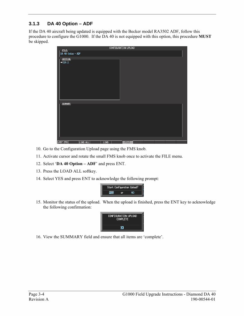
3.1.3 DA 40 Option – ADF
If the DA 40 aircraft being updated is equipped with the Becker model RA3502 ADF, follow this procedure to configure the G1000. If the DA 40 is not equipped with this option, this procedure MUST be skipped.
10. Go to the Configuration Upload page using the FMS knob.
11. Activate cursor and rotate the small FMS knob once to activate the FILE menu.
12. Select �DA 40 Option � ADF� and press ENT.
13. Press the LOAD ALL softkey.
14. Select YES and press ENT to acknowledge the following prompt:
15. Monitor the status of the upload. When the upload is finished, press the ENT key to acknowledge
the following confirmation:
16. View the SUMMARY field and ensure that all items are �complete�.
G1000 Field Upgrade Instructions - Diamond DA 40 Page 3-5 190-00544-01 Revision A
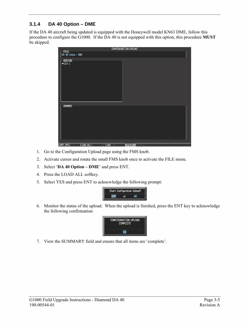
3.1.4 DA 40 Option – DME
If the DA 40 aircraft being updated is equipped with the Honeywell model KN63 DME, follow this procedure to configure the G1000. If the DA 40 is not equipped with this option, this procedure MUST be skipped.
1. Go to the Configuration Upload page using the FMS knob.
2. Activate cursor and rotate the small FMS knob once to activate the FILE menu.
3. Select �DA 40 Option � DME� and press ENT.
4. Press the LOAD ALL softkey.
5. Select YES and press ENT to acknowledge the following prompt:
6. Monitor the status of the upload. When the upload is finished, press the ENT key to acknowledge
the following confirmation:
7. View the SUMMARY field and ensure that all items are �complete�.
Page 3-6 G1000 Field Upgrade Instructions - Diamond DA 40 Revision A 190-00544-01
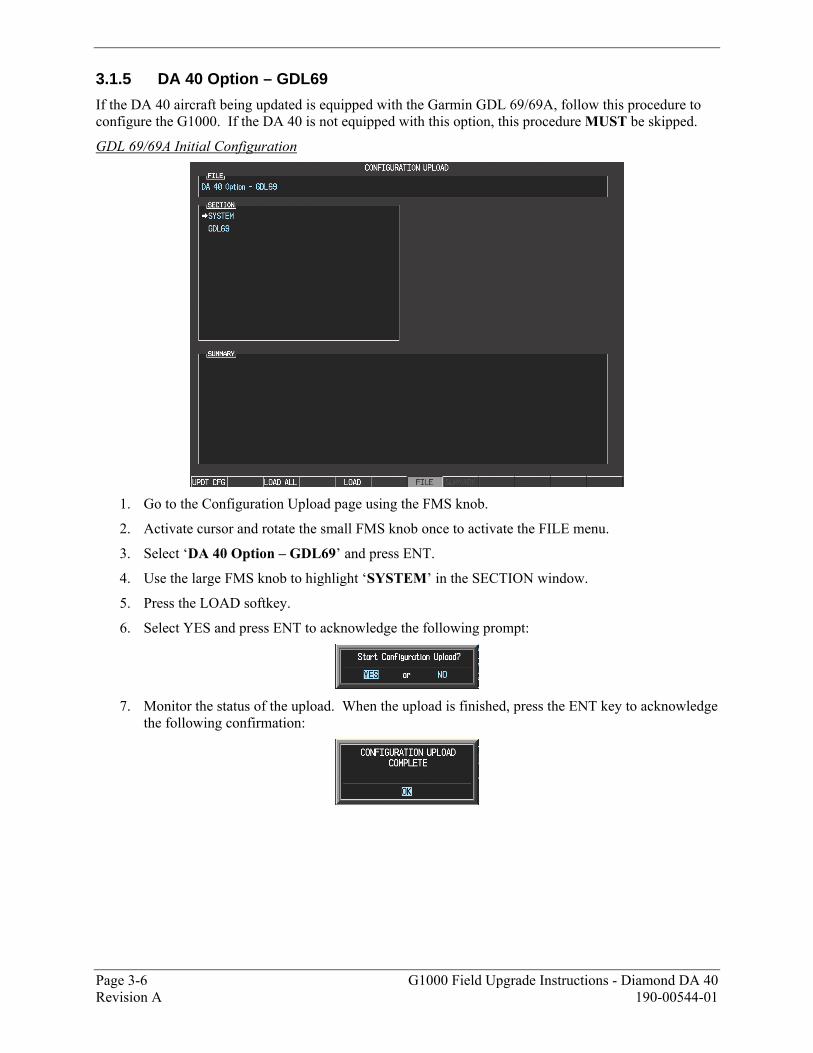
3.1.5 DA 40 Option – GDL69
If the DA 40 aircraft being updated is equipped with the Garmin GDL 69/69A, follow this procedure to configure the G1000. If the DA 40 is not equipped with this option, this procedure MUST be skipped.
GDL 69/69A Initial Configuration
1. Go to the Configuration Upload page using the FMS knob.
2. Activate cursor and rotate the small FMS knob once to activate the FILE menu.
3. Select �DA 40 Option � GDL69� and press ENT.
4. Use the large FMS knob to highlight �SYSTEM� in the SECTION window.
5. Press the LOAD softkey.
6. Select YES and press ENT to acknowledge the following prompt:
7. Monitor the status of the upload. When the upload is finished, press the ENT key to acknowledge
the following confirmation:
G1000 Field Upgrade Instructions - Diamond DA 40 Page 3-7 190-00544-01 Revision A
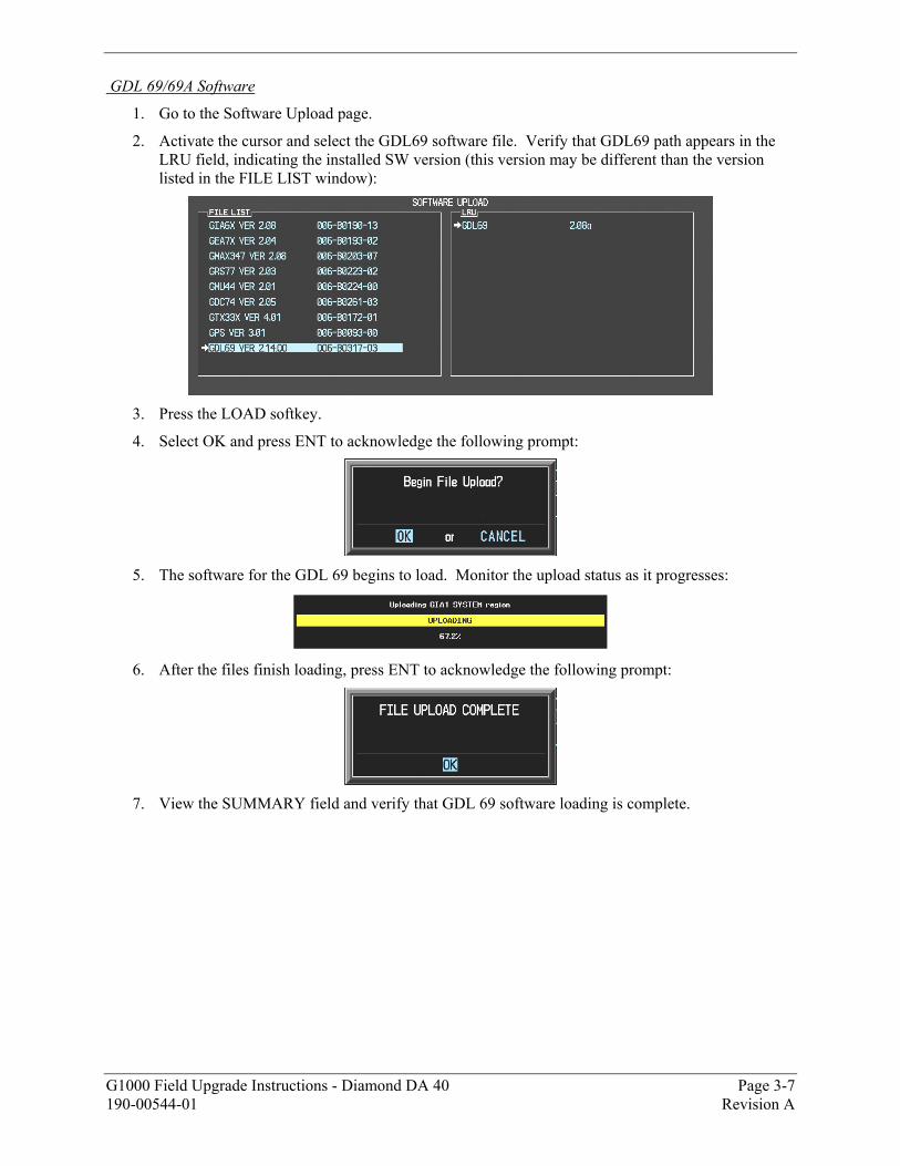
GDL 69/69A Software
1. Go to the Software Upload page.
2. Activate the cursor and select the GDL69 software file. Verify that GDL69 path appears in the LRU field, indicating the installed SW version (this version may be different than the version listed in the FILE LIST window):
3. Press the LOAD softkey.
4. Select OK and press ENT to acknowledge the following prompt:
5. The software for the GDL 69 begins to load. Monitor the upload status as it progresses:
6. After the files finish loading, press ENT to acknowledge the following prompt:
7. View the SUMMARY field and verify that GDL 69 software loading is complete.
Page 3-8 G1000 Field Upgrade Instructions - Diamond DA 40 Revision A 190-00544-01
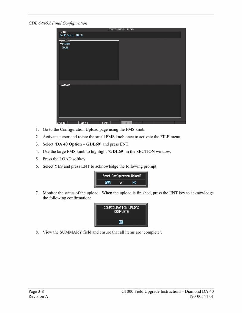
GDL 69/69A Final Configuration
1. Go to the Configuration Upload page using the FMS knob.
2. Activate cursor and rotate the small FMS knob once to activate the FILE menu.
3. Select �DA 40 Option � GDL69� and press ENT.
4. Use the large FMS knob to highlight �GDL69� in the SECTION window.
5. Press the LOAD softkey.
6. Select YES and press ENT to acknowledge the following prompt:
7. Monitor the status of the upload. When the upload is finished, press the ENT key to acknowledge
the following confirmation:
8. View the SUMMARY field and ensure that all items are �complete�.

G1000 Field Upgrade Instructions - Diamond DA 40 Page 4-1 190-00544-01 Revision A
4 Return to Service
4.1 Software Load Confirmation
1. Go to the System Status page using the small FMS knob. Activate the cursor and toggle to the
LRU window.
2. Highlight each of the following items in the LRU window, and verify that the software part number and version matches the G1000/DA40 Required Equipment List, 005-00305-00.
LRU SW VER & P/N OK LRU SW VER & P/N OK
PFD1 _____ GTX1 � GIA1 _____
MFD1 _____ GEA1 � GIA1 _____
GIA1 _____ GDC1 � GIA1 _____
GIA2 _____ GDC1 FPGA _____
GPS1 _____ GMA1 � GIA1 _____
GPS2 _____ GMU1 _____
GRS1 � GIA1 _____ GMU1 FPGA _____
GRS1 FPGA _____ GDL 69 (OPTIONAL) _____
3. De-activate the cursor. IMPORTANT!
If any software version and/or part number does not match those specified by table in the G1000/DA40 Required Equipment List, or if the software is not successfully loaded, DO NOT continue with post-installation procedures. Troubleshoot and resolve the issue before continuing.
Page 4-2 G1000 Field Upgrade Instructions - Diamond DA 40 Revision A 190-00544-01
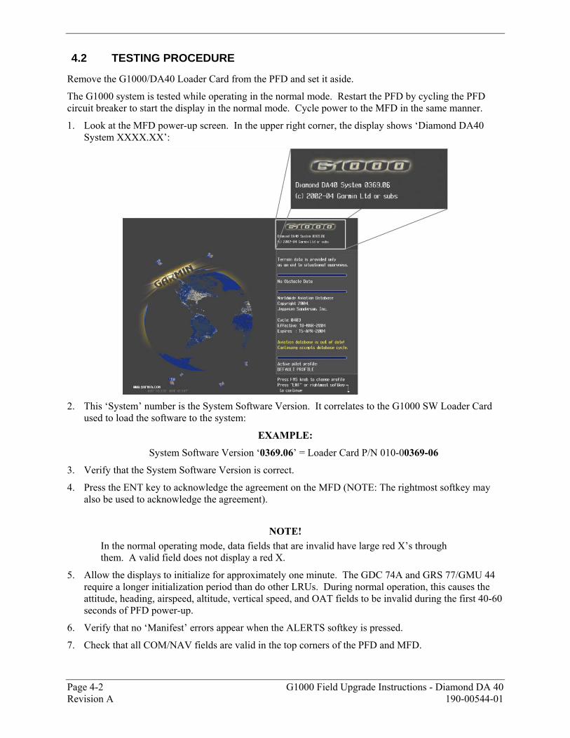
4.2 TESTING PROCEDURE
Remove the G1000/DA40 Loader Card from the PFD and set it aside.
The G1000 system is tested while operating in the normal mode. Restart the PFD by cycling the PFD circuit breaker to start the display in the normal mode. Cycle power to the MFD in the same manner.
1. Look at the MFD power-up screen. In the upper right corner, the display shows �Diamond DA40 System XXXX.XX�:
2. This �System� number is the System Software Version. It correlates to the G1000 SW Loader Card
used to load the software to the system:
EXAMPLE:
System Software Version �0369.06� = Loader Card P/N 010-00369-06
3. Verify that the System Software Version is correct.
4. Press the ENT key to acknowledge the agreement on the MFD (NOTE: The rightmost softkey may also be used to acknowledge the agreement).
NOTE!
In the normal operating mode, data fields that are invalid have large red X�s through them. A valid field does not display a red X.
5. Allow the displays to initialize for approximately one minute. The GDC 74A and GRS 77/GMU 44 require a longer initialization period than do other LRUs. During normal operation, this causes the attitude, heading, airspeed, altitude, vertical speed, and OAT fields to be invalid during the first 40-60 seconds of PFD power-up.
6. Verify that no �Manifest� errors appear when the ALERTS softkey is pressed.
7. Check that all COM/NAV fields are valid in the top corners of the PFD and MFD.

G1000 Field Upgrade Instructions - Diamond DA 40 Page 4-3 190-00544-01 Revision A
8. Check that attitude, heading, altitude, airspeed, vertical speed, TAS, and OAT fields are valid on the PFD.
9. Check that engine and airframe instruments are valid on the MFD.
10. Push the red DISPLAY BACKUP button on the GMA 1347. Verify both displays enter reversion mode: both should have valid attitude, altitude, airspeed, vertical speed, and engine instruments.
11. De-activate reversion mode by pushing the DISPLAY BACKUP button again.
12. The GIA 63 units should normally acquire a 3D GPS navigation solution within 5 to 10 minutes of
startup, provided the aircraft is outside (or indoors with a GPS repeater). Select the AUX � GPS STATUS Page on the MFD. Two softkeys on the bottom of the display allow the user to toggle between GPS 1 and GPS 2. Verify that both receivers show 3D Navigation on the MFD.
Page 4-4 G1000 Field Upgrade Instructions - Diamond DA 40 Revision A 190-00544-01
4.3 ADF Checkout
Perform this checkout only for aircraft that were upgraded with a newly installed ADF.
This check verifies that the ADF-to-G1000 interface operates correctly. This check is only required for DA40 aircraft with the remote-mount Becker RA3502 ADF installed.
1. On the PFD, check to see if the ADF window(s) is displayed. If not, press the PFD softkey. Using either the BRG1 or BRG2 softkeys, toggle the softkey until the ADF bearing is shown. Press the BACK softkey.
2. Verify that the ADF window is not invalid (no red �X�).
3. Press the ADF/DME softkey and check to ensure the ADF tuning window displays correctly.
4. Using the large FMS knob, highlight the ADF frequency field. Turn the small FMS knob to select the desired frequency. For this test select a known valid local ADF station and press the ENT softkey. Press the ENT again to activate the frequency field. Verify that the ADF bearing pointer moves towards a bearing and stabilizes.
5. Close the ADF/DME TUNING screen by pressing the ADF/DME softkey.
6. Verify that the audio from the station tuned can be heard on the pilots and copilots headset.
7. Verify that the audio from the station turned can be heard over the PA system.
8. On the PFD, press the ADF/DME softkey. Verify that the ADF/DME TUNING screen is displayed.
9. Change the ADF mode by using the large FMS knob to highlight the ADF mode field. Verify that ANT, BFO, and ADF can be displayed in the field by turning the small FMS knob. Verify that pressing the ENT softkey activates the desired field.
10. Change the ADF volume by using the large FMS knob to highlight the VOL level field �xx%�. Verify over the PA and headsets that the volume increases and decreases as indicated when the small FMS is used.

G1000 Field Upgrade Instructions - Diamond DA 40 Page 4-5 190-00544-01 Revision A
4.4 DME Checkout
This check verifies that the DME-to-G1000 interface operates correctly. This check is only required for DA40 aircraft with the Honeywell remote mounted KN63 DME installed.
1. On the PFD, check to see if the DME window is displayed. If not, press the PFD softkey, then press the DME softkey to display the DME window next to the HSI.
2. On the PFD, press the ADF/DME softkey. Verify that the ADF/DME TUNING screen is displayed.
3. With the ADF/DME TUNING screen activated, use the large FMS knob to highlight the DME field. Verify that the NAV1, NAV2 and HOLD modes can be selected by turning the small FMS knob.
4. Verify that NAV1 and NAV2 frequencies are set to 108.00 and 117.00.
5. Select the DME NAV1 mode by pressing the ENT softkey. Verify that the DME window display is set to the NAV1 frequency of 108.00.
6. Select the DME NAV2 mode by pressing the ENT softkey. Verify that the DME window display is set to the NAV2 frequency of 117.00.
7. Select the DME HOLD mode by pressing the ENT softkey. Verify that the last selected NAV frequency of 117.00 remains the same when the NAV2 frequency is changed.
8. On the NAV Test Set, set up a DME test and note the nav frequency. Tune NAV 1 to the test set frequency and set the DME MODE to NAV1. Ensure that NAV 2 is set to a frequency other than the test set frequency.
9. Verify that the DME distance on the PFD matches the test set.
10. Press the DME and SPKR buttons on the audio panel to select the DME audio and turn on the speaker. Verify that the DME audio can be heard over the speaker.
11. On the PFD, set the DME mode to NAV2 and verify that the DME distance is dashed out.
12. Tune NAV 2 to the test set frequency.
13. Verify that the DME distance on the PFD matches the test set.
Page 4-6 G1000 Field Upgrade Instructions - Diamond DA 40 Revision A 190-00544-01
4.5 GDL 69 Checkout
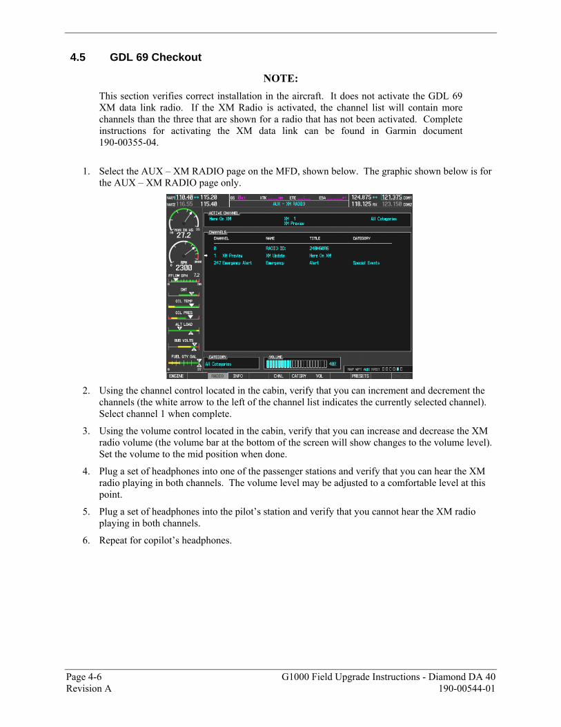
NOTE: This section verifies correct installation in the aircraft. It does not activate the GDL 69 XM data link radio. If the XM Radio is activated, the channel list will contain more channels than the three that are shown for a radio that has not been activated. Complete instructions for activating the XM data link can be found in Garmin document 190-00355-04.
1. Select the AUX � XM RADIO page on the MFD, shown below. The graphic shown below is for
the AUX � XM RADIO page only.
2. Using the channel control located in the cabin, verify that you can increment and decrement the
channels (the white arrow to the left of the channel list indicates the currently selected channel). Select channel 1 when complete.
3. Using the volume control located in the cabin, verify that you can increase and decrease the XM radio volume (the volume bar at the bottom of the screen will show changes to the volume level). Set the volume to the mid position when done.
4. Plug a set of headphones into one of the passenger stations and verify that you can hear the XM radio playing in both channels. The volume level may be adjusted to a comfortable level at this point.
5. Plug a set of headphones into the pilot�s station and verify that you cannot hear the XM radio playing in both channels.
6. Repeat for copilot�s headphones.

G1000 Field Upgrade Instructions - Diamond DA 40 Page 4-7 190-00544-01 Revision A
4.6 Aviation Database Loading (Optional)
1. Remove power from the PFD and MFD using the respectively labeled breakers.
2. Insert an SD card containing the current Jeppesen aviation database (card & data supplied by Jeppesen) into the top slot of the PFD.
3. Apply power to the PFD. The following prompt is displayed in the upper left corner of the PFD:
4. Press the ENT key to confirm the database update. The following prompt is displayed:
5. After the update completes, the PFD starts in normal mode. Remove the aviation database update
SD Card from the PFD.
6. Repeat steps 2 through 4 for the MFD. The MFD and PFD aviation databases are now updated.
7. Confirm that the correct update cycle and version is loaded at the power-up page of the MFD.
8. Remove power from the PFD and MFD using the respectively labeled breakers.
Remove the aviation database update SD Card from the MFD.
Page 4-8 G1000 Field Upgrade Instructions - Diamond DA 40 Revision A 190-00544-01
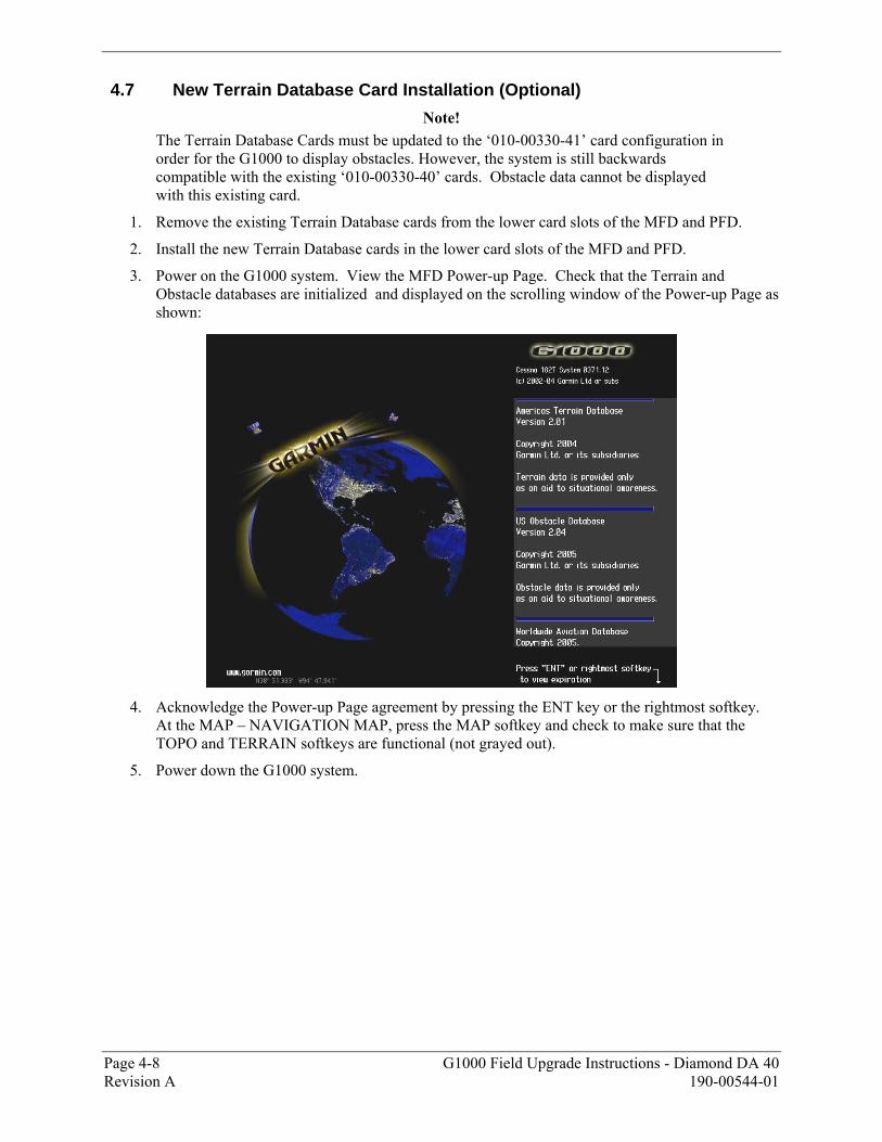
4.7 New Terrain Database Card Installation (Optional)
Note! The Terrain Database Cards must be updated to the �010-00330-41� card configuration in order for the G1000 to display obstacles. However, the system is still backwards compatible with the existing �010-00330-40� cards. Obstacle data cannot be displayed with this existing card.
1. Remove the existing Terrain Database cards from the lower card slots of the MFD and PFD.
2. Install the new Terrain Database cards in the lower card slots of the MFD and PFD.
3. Power on the G1000 system. View the MFD Power-up Page. Check that the Terrain and Obstacle databases are initialized and displayed on the scrolling window of the Power-up Page as shown:
4. Acknowledge the Power-up Page agreement by pressing the ENT key or the rightmost softkey.
At the MAP � NAVIGATION MAP, press the MAP softkey and check to make sure that the TOPO and TERRAIN softkeys are functional (not grayed out).
5. Power down the G1000 system.
G1000 Field Upgrade Instructions - Diamond DA 40 Page 4-9 190-00544-01 Revision A
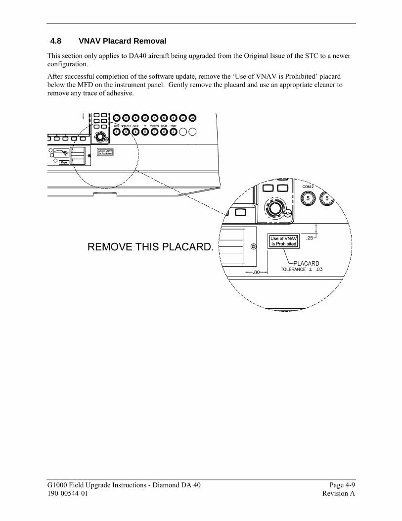
4.8 VNAV Placard Removal
This section only applies to DA40 aircraft being upgraded from the Original Issue of the STC to a newer configuration.
After successful completion of the software update, remove the �Use of VNAV is Prohibited� placard below the MFD on the instrument panel. Gently remove the placard and use an appropriate cleaner to remove any trace of adhesive.
Page 4-10 G1000 Field Upgrade Instructions - Diamond DA 40 Revision A 190-00544-01
4.9 Aircraft Logbook Entry
The update of the G1000 is complete. Be sure to push the �YAW GYRO�, �HORIZON�, and �AP� circuit breakers in, if they were pulled.
Before returning the aircraft to service, make the appropriate entry in aircraft�s maintenance records, noting that this upgrade has been performed. Record the G1000/DA40 Loader Card part number in the maintenance records.
Ensure that the required documentation is delivered to the aircraft owner and/or operator.
Return the aircraft to service in accordance with applicable FAA-requirements.
G1000 Field Upgrade Instructions - Diamond DA 40 Page 5-1 190-00544-01 Revision A
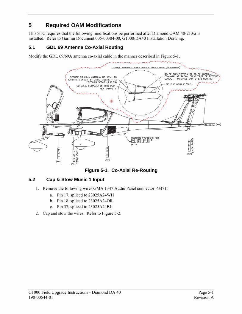
5 Required OAM Modifications This STC requires that the following modifications be performed after Diamond OAM 40-213/a is installed. Refer to Garmin Document 005-00304-00, G1000/DA40 Installation Drawing.
5.1 GDL 69 Antenna Co-Axial Routing
Modify the GDL 69/69A antenna co-axial cable in the manner described in Figure 5-1.
Figure 5-1. Co-Axial Re-Routing
5.2 Cap & Stow Music 1 Input
1. Remove the following wires GMA 1347 Audio Panel connector P3471: a. Pin 17, spliced to 23025A24WH b. Pin 18, spliced to 23025A24OR c. Pin 37, spliced to 23025A24BL
2. Cap and stow the wires. Refer to Figure 5-2.

Page 5-2 G1000 Field Upgrade Instructions - Diamond DA 40 Revision A 190-00544-01
Figure 5-2. Music 2 Input Cap and Stow