diatron - arcus user manual
TRANSCRIPT

AArrccuuss Hematology Analyzer
User’s Manual
2.1 release
Arcus User's Manual 1
CONTENTS
1. INTRODUCTION, INTENDED USE ........................................................................................................ 3
2. DESCRIPTION OF THE ANALYZER ..................................................................................................... 3
2.1 PARTS OF THE ANALYZER............................................................................................................................ 3 Front panel ..................................................................................................................................................... 4 Rear panel ...................................................................................................................................................... 5
2.2 FLUIDIC SCHEMATICS ................................................................................................................................. 6 2.3 FUNCTION OF FLUIDICS ............................................................................................................................... 6 2.4 CONTROL PANELS ....................................................................................................................................... 6
2.4.1 Sampling bar ..................................................................................................................................... 6 2.4.2 Status LED......................................................................................................................................... 6 2.4.3 Display............................................................................................................................................... 6 2.4.4 Keyboard ........................................................................................................................................... 7
3. DESCRIPTION OF THE SOFTWARE..................................................................................................... 8
3.1 GENERAL .................................................................................................................................................... 8 3.2 MENU SYSTEM ............................................................................................................................................ 8 3.3 MENU STRUCTURE ...................................................................................................................................... 9
4. OPERATING PRINCIPLES..................................................................................................................... 10
4.1 IMPEDANCE METHOD................................................................................................................................. 10 4.2 PRINCIPLE OF THE HGB MEASUREMENT................................................................................................... 10 4.3 PARAMETERS ............................................................................................................................................ 11 4.4 ABSOLUTE AND LINEARITY RANGES OF MEASURED PARAMETERS........................................................... 12
5. ANALYZER INSTALLATION PROCEDURES.................................................................................... 13
5.1 UNPACKING .............................................................................................................................................. 13 5.2 CONNECTING REAGENT CONTAINERS ........................................................................................................ 13 5.3 CONNECTING POWER CORD ....................................................................................................................... 13 5.4 CONNECTING AN EXTERNAL PRINTER........................................................................................................ 13 5.5 CONNECTING THE INSTRUMENT TO A HOST COMPUTER ............................................................................. 14 5.6 TURNING THE INSTRUMENT ON ................................................................................................................ 14 5.7 REAGENT PRIMING .................................................................................................................................... 14 5.8 TURNING THE INSTRUMENT OFF............................................................................................................... 15
6. SOFTWARE SETTINGS .......................................................................................................................... 16
6.1 SETTING DATE AND TIME.......................................................................................................................... 16 6.2 SETTING THE NAME OF THE LABORATORY ................................................................................................ 17 6.3 RESULTS UNITS SETTING ........................................................................................................................... 17 6.4 SETTING REFERENCE LIMITS...................................................................................................................... 18 6.5 FLUID SENSORS ......................................................................................................................................... 19 6.6 PRINTER SETTINGS .................................................................................................................................... 20
6.6.1 Troubleshooting guide for printing problems ................................................................................. 22 6.7 USER SETTINGS ......................................................................................................................................... 23
6.7.1 Multi-user mode .............................................................................................................................. 24
7. ROUTINE UTILIZATION........................................................................................................................ 25
7.1 MEASURING PROCESS................................................................................................................................ 25 7.1.1 Sampling.......................................................................................................................................... 25 7.1.2 Blank measurement ......................................................................................................................... 25 7.1.3 Calibration ...................................................................................................................................... 26 7.1.4 Sample Analysis............................................................................................................................... 29 7.1.5 Prediluted mode .............................................................................................................................. 32
7.2 QUALITY CONTROL ................................................................................................................................... 33 7.2.1 QC database .................................................................................................................................... 34
7.3 AUTO STAND-BY ....................................................................................................................................... 35 7.4 PRINTOUTS................................................................................................................................................ 35 7.5 PATIENT RESULTS DATABASE MANAGEMENT ............................................................................................ 36 7.6 DATA BACK UP ......................................................................................................................................... 38
Diatron Ltd. 2
7.7 MAINTENANCE ..........................................................................................................................................39 7.7.1 Cleaning...........................................................................................................................................39 7.7.2 Priming ............................................................................................................................................39 7.7.3 Draining...........................................................................................................................................39 7.7.4 Manual cleaning of the aperture .....................................................................................................40 7.7.5 Weekly maintenance ........................................................................................................................40
7.8 DIAGNOSTICS ............................................................................................................................................41 7.8.1 Device Statistics...............................................................................................................................41 7.8.2 Self test.............................................................................................................................................41
7.9 SOFTWARE UPDATE ...................................................................................................................................42
8. APPENDIX "A": REAGENT SOLUTIONS AND CONSUMPTION ..................................................43
9. APPENDIX "B": TECHNICAL SPECIFICATIONS ............................................................................44
10. APPENDIX "C": FLUIDIC SCHEMATICS ......................................................................................45
11. APPENDIX "D": ACCESSORIES.......................................................................................................46

Arcus User's Manual 3
1. INTRODUCTION, INTENDED USE
Arcus hematology analyzer is a fully automated cell counter for in vitro diagnostic use. The compact instrument was developed for small to medium size labs with today’s technology.
The analyzer can process 35 samples per hour with the specified accuracy and reproducibility and has a 2,000 samples storage capacity including histograms.
It is intended to determine the following 18 hematology parameters from a 25 µl whole blood sample:
• WBC - LYM# - MID# - GRA# - LYM% - MID% - GRA% (three-part WBC differential) • HGB - RBC - HCT - MCV - RDW - MCH - MCHC • PLT - MPV - PCT - PDW
The interfaces allow sending results to an external printer (parallel port), to a host computer (serial port). By using the integrated 3½” floppy disk drive, the instrument can be easily upgraded at any time and it can backup data to floppy disk.
2. DESCRIPTION OF THE ANALYZER
2.1 Parts of the analyzer
Arcus Hematology Analyzer consists of three main parts: • Fluidic System: performs aspirating, sampling, diluting, mixing, lysing and rinsing,
and additionally generates the regulated measuring vacuum. • Data Processing System: counts and measures blood parameters, generates
and stores results and histograms. • Control Panels: include display, keyboard, parallel (external printer), and serial
(computer) interface.
Diatron Ltd. 4
2.1.1 Front panel
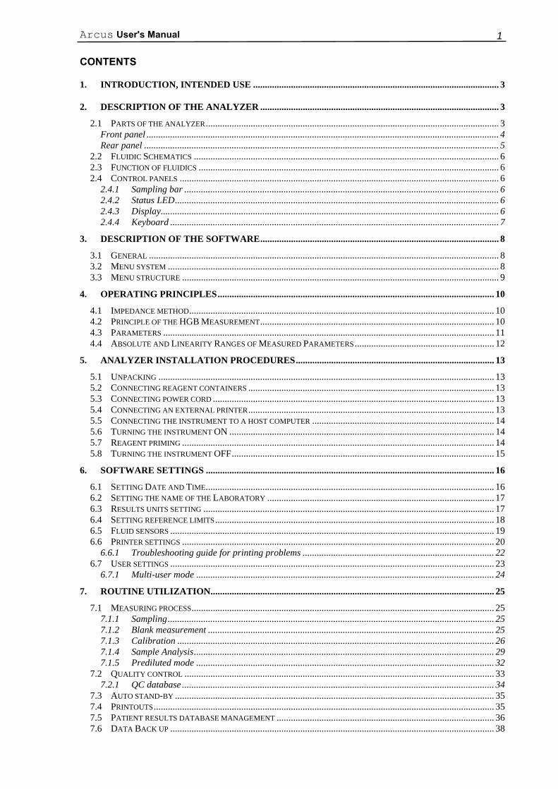
Figure 1. Front view
1. Floppy disk drive
2. Function buttons
3. Graphic liquid crystal display (LCD)
4. Numerical keypad
5. Delete key
6. HELP key
7. START/OK button
8. Cursor moving buttons
9. Glowing LED
10. Sampling bar
2
1
3
4 5
6
7
8
9
10

Arcus User's Manual 5
2.1.2 Rear panel
Figure 2. Rear view
1. Reagent tubing connections
2. External keyboard connector
3. Opening for air-flow rotor
4. Power input
5. 115/230 V selector
6. Small power switch for separating the instrument from the mains power
7. Serial (RS 232) connector for computer
8. Printer connector for external printer
9. On/Off switch
1
2
3
4
8
9
5
6
7
Diatron Ltd. 6
2.2 Fluidic Schematics
See Appendix “C”.
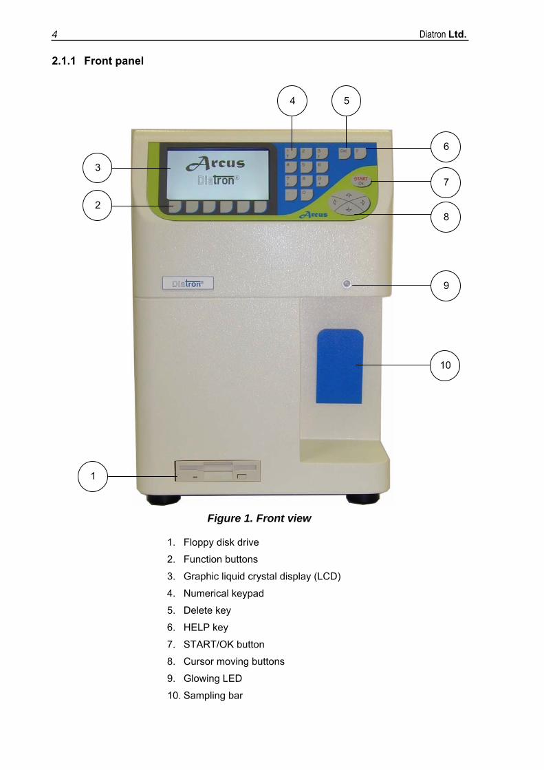
2.3 Function of fluidics
Sample flow prior to counting: 25 µl (50 µl in Prediluted mode) of anti-coagulated whole blood sample is aspirated by the sampling needle, and 4 ml of diluent is added into the chamber. 25 µl of primary dilution is aspirated and stored in the needle during the WBC measurement. 0.9 ml of lysing reagent is added to the primary dilution remaining in the chamber. After the WBC measurement and a washing process, the instrument makes the second dilution into the chamber with the sample stored in the needle and with 5 ml of diluent reagent.
Dilution rates: 1. Primary dilution 1:160 2. RBC dilution 1:32,000 3. WBC dilution 1:196
Measurement times: 1. WBC counting 8 seconds 2. HGB measurement 3 seconds 3. RBC/PLT counting: 8 seconds
2.4 Control panels
2.4.1 Sampling bar A push on the sampling bar triggers a measurement process.
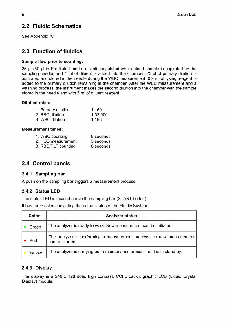
2.4.2 Status LED The status LED is located above the sampling bar (START button)
It has three colors indicating the actual status of the Fluidic System:
Color Analyzer status
• Green The analyzer is ready to work. New measurement can be initiated.
• Red The analyzer is performing a measurement process, no new measurement can be started.
• Yellow The analyzer is carrying out a maintenance process, or it is in stand-by.
2.4.3 Display
The display is a 240 x 128 dots, high contrast, CCFL backlit graphic LCD (Liquid Crystal Display) module.
Arcus User's Manual 7
2.4.4 Keyboard
Keyboard is a 24-button foil keypad, including:
• Numerical buttons: for entering numerical data, and selecting menu items; • Function buttons: for starting the action displayed with an icon above the function key
at the bottom of the LCD; • Cursor moving arrows: ↑ and ↓, for moving between database items;
← and →, for moving between parameter columns or menu levels; • START/OK button: used for initiating a measurement cycle or confirming data; • Del button: for deleting missed characters; • Help button: for HELP function.
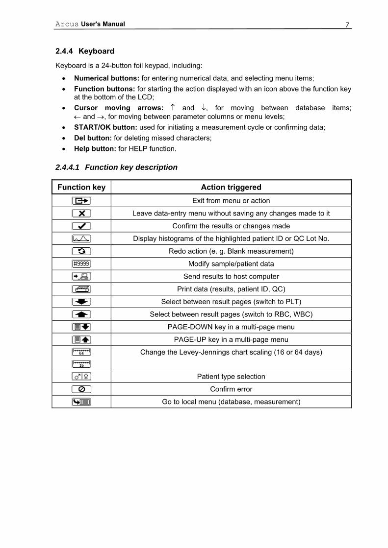
2.4.4.1 Function key description
Function key Action triggered
Exit from menu or action
Leave data-entry menu without saving any changes made to it
Confirm the results or changes made
Display histograms of the highlighted patient ID or QC Lot No.
Redo action (e. g. Blank measurement)
Modify sample/patient data
Send results to host computer
Print data (results, patient ID, QC)
Select between result pages (switch to PLT)
Select between result pages (switch to RBC, WBC)
PAGE-DOWN key in a multi-page menu
PAGE-UP key in a multi-page menu
Change the Levey-Jennings chart scaling (16 or 64 days)
Patient type selection
Confirm error
Go to local menu (database, measurement)
Diatron Ltd. 8
3. DESCRIPTION OF THE SOFTWARE
3.1 General
The integrated software controls instrument operations, displays, stores, recalls data, and allows the User to perform quality control (QC) and calibration procedures.
Pressing the START/OK button validates newly entered data, or activates/enters the highlighted item.
3.2 Menu system
The instrument uses a menu system to initiate actions, and to modify settings. In the menu system there are three ways to navigate between menus and menu items.
• Position the selection bar to the desired item with the ↑ and ↓ buttons and press the START/OK button. This will validate the highlighted menu item. Press the function key to return to the previous menu level. This method is suggested while learning instrument operation.
• Pressing the number that corresponds to the desired menu item will also validate it. In this case there is no need to press START/OK. Pressing the 0 (zero) button has the same effect as the function key. This method is much more efficient in practice.
• You can move between the higher and lower menu levels by the ← and → keys.
The existence of sub-menus are indicated by a ► symbol at the end of the menu line.
Some results can be displayed in table format. In this case the 3 (three) button has the same effect as the Page Up key, and the 9 (nine) button has the same effect as the Page Down key. Use these buttons to move between table pages. Further positioning keys during browsing the database are 1 (Jump to top) and 7 (Jump to bottom).
Some menu items have selected and deselected (on and off) states. These items are marked with a symbol in front of the item number. The filled mark indicates selected state. Selecting the menu item toggles its state.
Other menu items work as so-called “radio-buttons”. It means that only one of the buttons of the group can be on at once. In some cases, more buttons are displayed together, though they correspond to different groups. In this case, the groups are separated by a horizontal line.
Arcus User's Manual 9
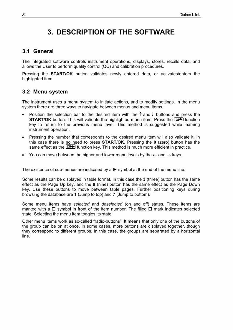
3.3 Menu structure MeasureDatabaseMaintenanceCalibrationQuality controlSettingsShut down
CleaningPrimingDrain chamberEmpty waste containerDiagnosticsService
Date and TimeLaboratoryUnitsLimitsFluid sensorsPrinter settingsUser settings
Prime allPrime diluentPrime lysePrime cleaner
Device informationStatisticsSelf test
Set date and timeDay.Month.YearMonth.Day.YearYear.Month.Day
Back up one dayBack up selected
MeasureMeasure blankPatient type
View databaseBackup databaseRestore and view
CalibrateView calibrationsCalibration settings
Calibrate MCV and MPVCalibrate HCT and PCTFactorial calibrationCalibration with one measureCalibration with two measuresCalibration with three measuresCalibrate prediluted mode
Set QC referenceQC measureView table of QC measuresView QC diagramSet QC level
QC Level 1QC Level 2QC Level 3QC Level 4QC Level 5QC Level 6
HumanMaleFemaleBabyToddlerChild
Diluent & CleanerLyseWaste
Shut downLogoutPreparing for shipment
Single user modeMulti user modeAdd new user
Go to specified recordSelectionChange sort orderBackup selected recordsSend selected recordsDelete selected records
Local menu
Prediluted modeMaintenanceRepeat last sample
CleaningPrimingDrain chamber
Prime allPrime diluentPrime lysePrime cleaner
Local menu
Select by Date, Time and IDSelect allDeselect all
UnsortedSort by timeSort by sample IDSort by patient ID
Diatron Ltd. 10
4. OPERATING PRINCIPLES
4.1 Impedance method
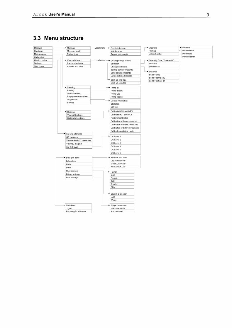
The impedance method counts and sizes cells by detecting and measuring changes in electrical impedance when a particle in a conductive liquid passes through a small aperture.
Each cell, passing through the aperture – where a constant DC current flows between the external and internal electrodes – causes some change in the impedance of the conductive blood cell suspension. These changes are recorded as increases in the voltage between the electrodes.
The number of pulses correlates to the number of particles (CBC - Counting Blood Cell). The intensity of each pulse is proportional to the volume of that particle (WBC, RBC, PLT histograms). Pulses are counted only in channels (in terms of femtoliters, fl) which are between the pre-set lower and upper discriminators.
4.2 Principle of the HGB Measurement
The lysed 1:196 sample dilution is measured by a cyanmethemoglobin method. The reagent lyses the red blood cells releasing hemoglobin.
Hemoglobin iron is converted from the ferrous (Fe2+) to the ferric (Fe3+) state to form methemoglobin, which combines with potassium cyanide (KCN) to produce the stable cyanmethemoglobin, or hemiglobincyanide. After that, the HGB concentration is measured photometrically.
The above mentioned measuring method is used to determine the HGB concentration. The HGB concentration can be measured using cyan-free lysing reagents as well.
-
+Blood cell suspensionExternal electrode
Internal electrodeAperture
Arcus User's Manual 11
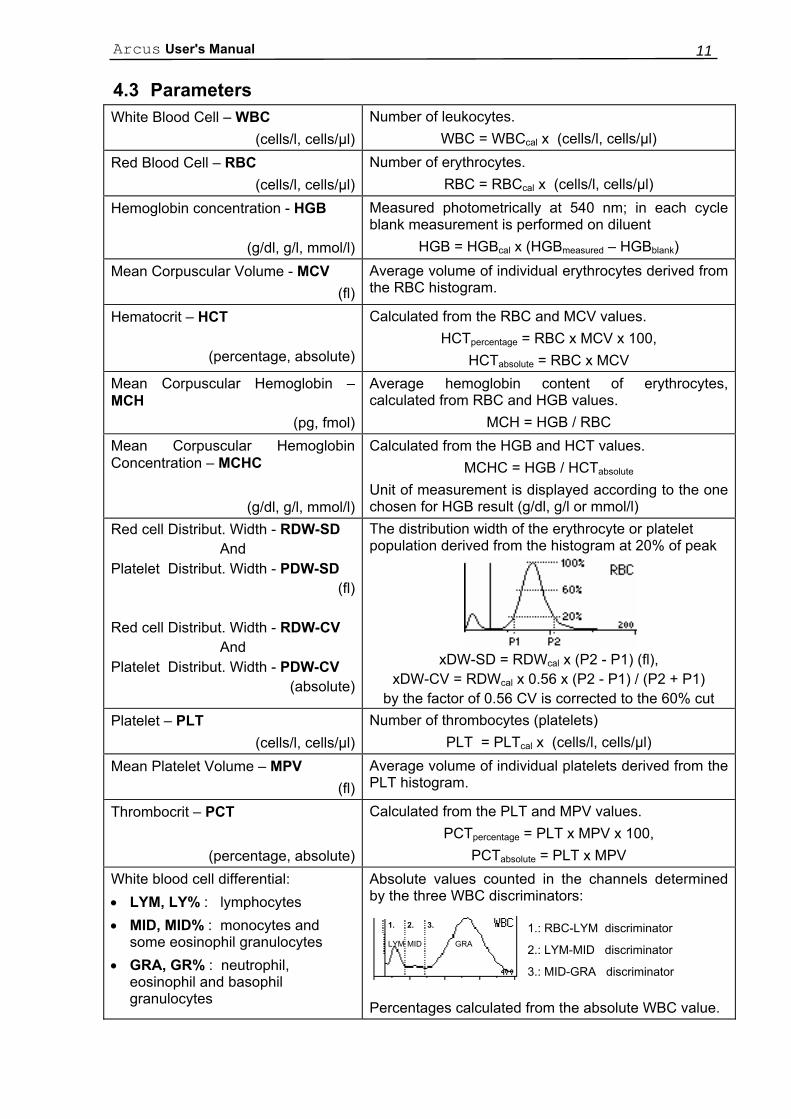
4.3 Parameters White Blood Cell – WBC
(cells/l, cells/µl)Number of leukocytes.
WBC = WBCcal x (cells/l, cells/µl) Red Blood Cell – RBC
(cells/l, cells/µl)Number of erythrocytes.
RBC = RBCcal x (cells/l, cells/µl) Hemoglobin concentration - HGB
(g/dl, g/l, mmol/l)
Measured photometrically at 540 nm; in each cycle blank measurement is performed on diluent
HGB = HGBcal x (HGBmeasured – HGBblank)
Mean Corpuscular Volume - MCV (fl)
Average volume of individual erythrocytes derived from the RBC histogram.
Hematocrit – HCT
(percentage, absolute)
Calculated from the RBC and MCV values. HCTpercentage = RBC x MCV x 100,
HCTabsolute = RBC x MCV Mean Corpuscular Hemoglobin – MCH
(pg, fmol)
Average hemoglobin content of erythrocytes, calculated from RBC and HGB values.
MCH = HGB / RBC Mean Corpuscular Hemoglobin Concentration – MCHC
(g/dl, g/l, mmol/l)
Calculated from the HGB and HCT values. MCHC = HGB / HCTabsolute
Unit of measurement is displayed according to the one chosen for HGB result (g/dl, g/l or mmol/l)
Red cell Distribut. Width - RDW-SD And
Platelet Distribut. Width - PDW-SD (fl)
Red cell Distribut. Width - RDW-CV
And Platelet Distribut. Width - PDW-CV
(absolute)
The distribution width of the erythrocyte or platelet population derived from the histogram at 20% of peak
xDW-SD = RDWcal x (P2 - P1) (fl),
xDW-CV = RDWcal x 0.56 x (P2 - P1) / (P2 + P1) by the factor of 0.56 CV is corrected to the 60% cut
Platelet – PLT
(cells/l, cells/µl)Number of thrombocytes (platelets)
PLT = PLTcal x (cells/l, cells/µl) Mean Platelet Volume – MPV
(fl)Average volume of individual platelets derived from the PLT histogram.
Thrombocrit – PCT
(percentage, absolute)
Calculated from the PLT and MPV values. PCTpercentage = PLT x MPV x 100,
PCTabsolute = PLT x MPV White blood cell differential: • LYM, LY% : lymphocytes • MID, MID% : monocytes and
some eosinophil granulocytes • GRA, GR% : neutrophil,
eosinophil and basophil granulocytes
Absolute values counted in the channels determined by the three WBC discriminators:
Percentages calculated from the absolute WBC value.
1.: RBC-LYM discriminator
2.: LYM-MID discriminator
3.: MID-GRA discriminator
GRA MIDLYM
1. 2. 3.
Diatron Ltd. 12
4.4 Absolute and Linearity Ranges of Measured Parameters
In the linearity range, the instrument works within the specified accuracy. Out of this linearity range, the system is able to display the results, but without the specified terms.
If the value is over the maximum range, the instrument can not measure it and the result is marked with an E (Error) flag. In this case, pre-dilution of the sample is recommended (e.g. very high WBC). For the Prediluted mode see section 7.1.5 of this manual.
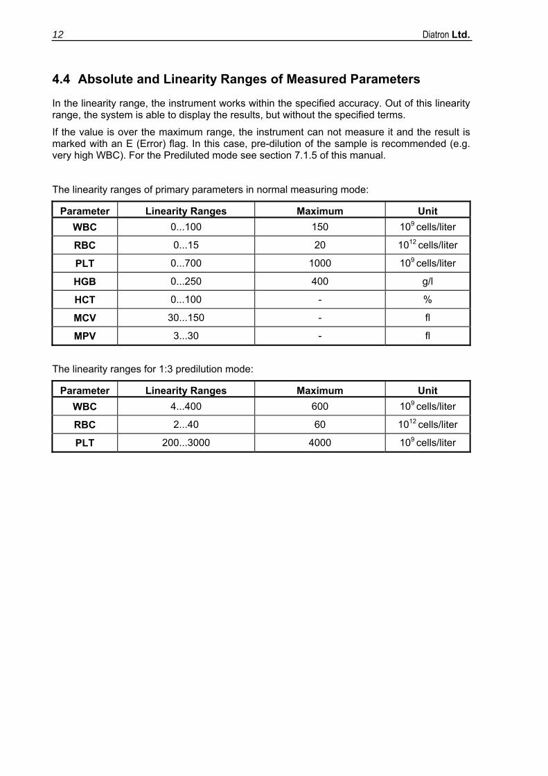
The linearity ranges of primary parameters in normal measuring mode:
Parameter Linearity Ranges Maximum Unit WBC 0...100 150 109 cells/liter
RBC 0...15 20 1012 cells/liter
PLT 0...700 1000 109 cells/liter
HGB 0...250 400 g/l
HCT 0...100 - %
MCV 30...150 - fl
MPV 3...30 - fl
The linearity ranges for 1:3 predilution mode:
Parameter Linearity Ranges Maximum Unit WBC 4...400 600 109 cells/liter
RBC 2...40 60 1012 cells/liter
PLT 200...3000 4000 109 cells/liter
Arcus User's Manual 13
5. ANALYZER INSTALLATION PROCEDURES
5.1 Unpacking
Only trained Service Personnel should perform unpacking. It's recommended to carefully inspect for any damage or missing items at the time of unpacking.
CAUTION! Before the first operation, let the instrument warm up to room temperature for at least 6 hours; otherwise the temperature gradient could cause water condensation, which may damage the electronic parts.
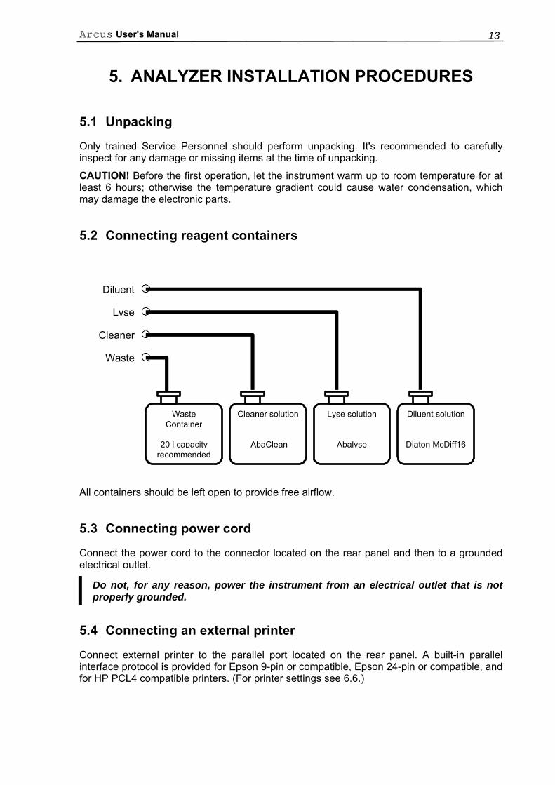
5.2 Connecting reagent containers
All containers should be left open to provide free airflow.
5.3 Connecting power cord
Connect the power cord to the connector located on the rear panel and then to a grounded electrical outlet.
Do not, for any reason, power the instrument from an electrical outlet that is not properly grounded.
5.4 Connecting an external printer
Connect external printer to the parallel port located on the rear panel. A built-in parallel interface protocol is provided for Epson 9-pin or compatible, Epson 24-pin or compatible, and for HP PCL4 compatible printers. (For printer settings see 6.6.)
WasteContainer
20 l capacityrecommended
Cleaner solution
AbaClean
Lyse solution
Abalyse
Diluent solution
Diaton McDiff16
Diluent
Lyse
Cleaner
Waste
Diatron Ltd. 14
5.5 Connecting the instrument to a host computer
The instrument has a built-in serial communication protocol that allows connecting the analyzer to a host computer. This serial interface is able to send results (including histograms) to the host computer. The serial I/O settings are in the service menu system. Therefore if you want to connect your instrument to a host computer, please call your Service Person.
5.6 Turning the instrument ON
1. Turn on the connected external printer
2. Turn on the power supply of the instrument by flipping the small power switch to I position.
3. Press the large switch located on the left side of the rear panel to power up the instrument.
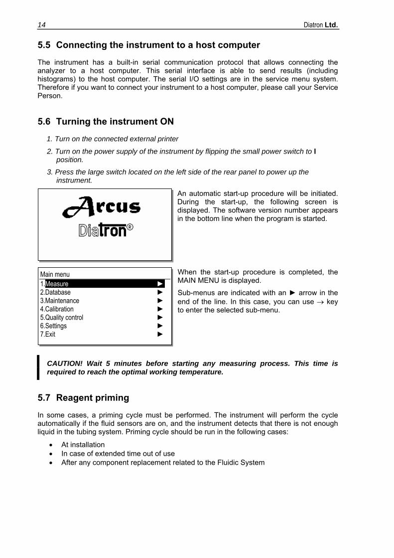
An automatic start-up procedure will be initiated. During the start-up, the following screen is displayed. The software version number appears in the bottom line when the program is started.
When the start-up procedure is completed, the MAIN MENU is displayed.
Sub-menus are indicated with an ► arrow in the end of the line. In this case, you can use → key to enter the selected sub-menu.
CAUTION! Wait 5 minutes before starting any measuring process. This time is required to reach the optimal working temperature.
5.7 Reagent priming
In some cases, a priming cycle must be performed. The instrument will perform the cycle automatically if the fluid sensors are on, and the instrument detects that there is not enough liquid in the tubing system. Priming cycle should be run in the following cases:
• At installation • In case of extended time out of use • After any component replacement related to the Fluidic System
Main menu 1.Measure ► 2.Database ► 3.Maintenance ► 4.Calibration ► 5.Quality control ► 6.Settings ► 7.Exit ►
Arcus User's Manual 15
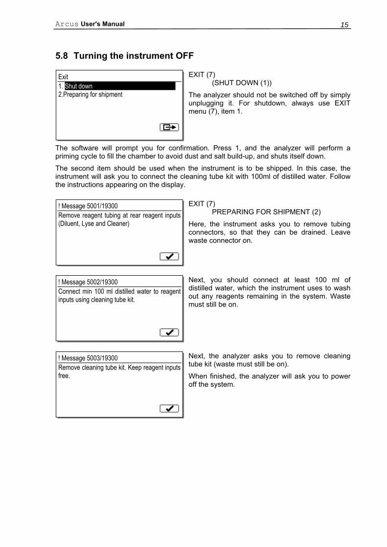
5.8 Turning the instrument OFF
EXIT (7) (SHUT DOWN (1))
The analyzer should not be switched off by simply unplugging it. For shutdown, always use EXIT menu (7), item 1.
The software will prompt you for confirmation. Press 1, and the analyzer will perform a priming cycle to fill the chamber to avoid dust and salt build-up, and shuts itself down.
The second item should be used when the instrument is to be shipped. In this case, the instrument will ask you to connect the cleaning tube kit with 100ml of distilled water. Follow the instructions appearing on the display.
EXIT (7) PREPARING FOR SHIPMENT (2)
Here, the instrument asks you to remove tubing connectors, so that they can be drained. Leave waste connector on.
Next, you should connect at least 100 ml of distilled water, which the instrument uses to wash out any reagents remaining in the system. Waste must still be on.
Next, the analyzer asks you to remove cleaning tube kit (waste must still be on).
When finished, the analyzer will ask you to power off the system.
Exit 1. Shut down 2.Preparing for shipment
! Message 5001/19300 Remove reagent tubing at rear reagent inputs (Diluent, Lyse and Cleaner)
! Message 5002/19300 Connect min 100 ml distilled water to reagent inputs using cleaning tube kit.
! Message 5003/19300 Remove cleaning tube kit. Keep reagent inputs free.
Diatron Ltd. 16
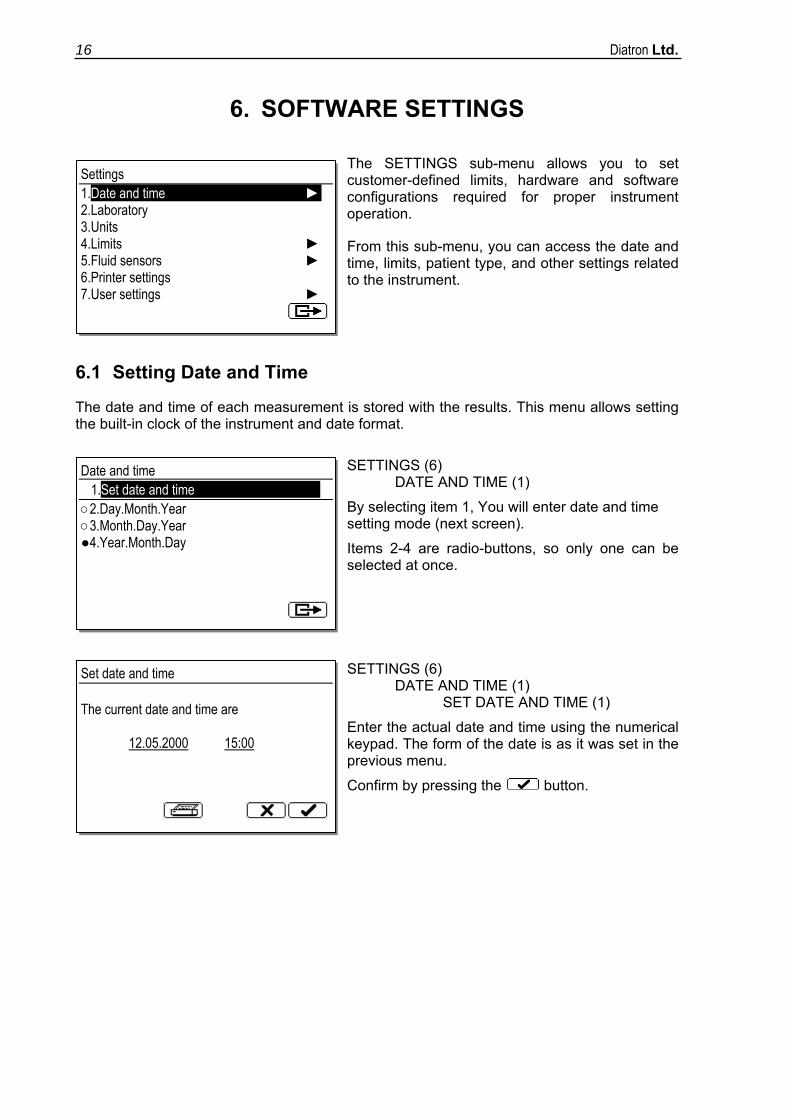
6. SOFTWARE SETTINGS
The SETTINGS sub-menu allows you to set customer-defined limits, hardware and software configurations required for proper instrument operation.
From this sub-menu, you can access the date and time, limits, patient type, and other settings related to the instrument.
6.1 Setting Date and Time
The date and time of each measurement is stored with the results. This menu allows setting the built-in clock of the instrument and date format.
SETTINGS (6) DATE AND TIME (1)
By selecting item 1, You will enter date and time setting mode (next screen).
Items 2-4 are radio-buttons, so only one can be selected at once.
SETTINGS (6) DATE AND TIME (1) SET DATE AND TIME (1)
Enter the actual date and time using the numerical keypad. The form of the date is as it was set in the previous menu.
Confirm by pressing the button.
Settings 1.Date and time ► 2.Laboratory 3.Units 4.Limits ► 5.Fluid sensors ► 6.Printer settings 7.User settings ►
Date and time 1.Set date and time ○2.Day.Month.Year ○3.Month.Day.Year ●4.Year.Month.Day
Set date and time The current date and time are 12.05.2000 15:00
Arcus User's Manual 17
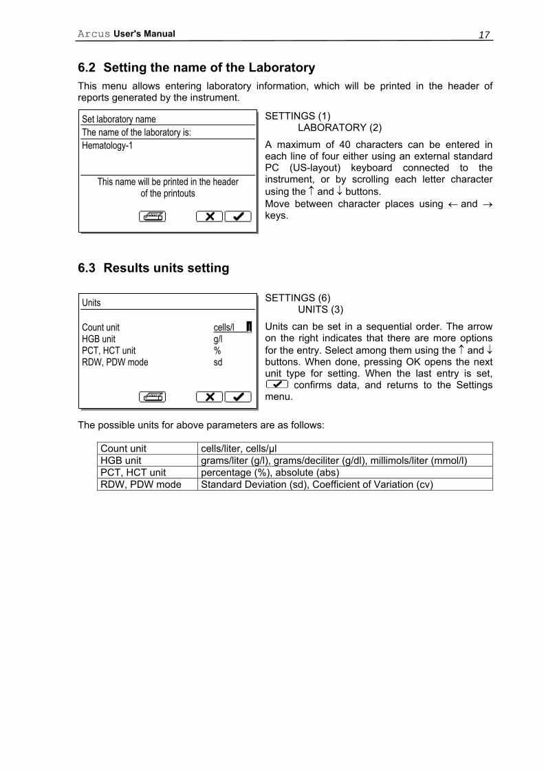
6.2 Setting the name of the Laboratory This menu allows entering laboratory information, which will be printed in the header of reports generated by the instrument.
SETTINGS (1) LABORATORY (2)
A maximum of 40 characters can be entered in each line of four either using an external standard PC (US-layout) keyboard connected to the instrument, or by scrolling each letter character using the ↑ and ↓ buttons. Move between character places using ← and → keys.
6.3 Results units setting
SETTINGS (6) UNITS (3)
Units can be set in a sequential order. The arrow on the right indicates that there are more options for the entry. Select among them using the ↑ and ↓ buttons. When done, pressing OK opens the next unit type for setting. When the last entry is set,
confirms data, and returns to the Settings menu.
The possible units for above parameters are as follows:
Count unit cells/liter, cells/µl HGB unit grams/liter (g/l), grams/deciliter (g/dl), millimols/liter (mmol/l) PCT, HCT unit percentage (%), absolute (abs) RDW, PDW mode Standard Deviation (sd), Coefficient of Variation (cv)
Set laboratory name The name of the laboratory is: Hematology-1
This name will be printed in the header of the printouts
Units Count unit cells/l ↓ HGB unit g/l PCT, HCT unit % RDW, PDW mode sd
Diatron Ltd. 18
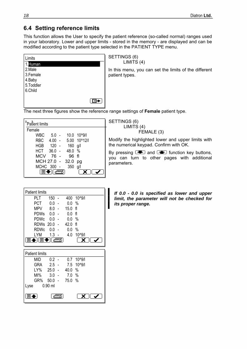
6.4 Setting reference limits This function allows the User to specify the patient reference (so-called normal) ranges used in your laboratory. Lower and upper limits - stored in the memory - are displayed and can be modified according to the patient type selected in the PATIENT TYPE menu.
SETTINGS (6) LIMITS (4)
In this menu, you can set the limits of the different patient types.
The next three figures show the reference range settings of Female patient type.
SETTINGS (6) LIMITS (4) FEMALE (3)
Modify the highlighted lower and upper limits with the numerical keypad. Confirm with OK.
By pressing and function key buttons, you can turn to other pages with additional parameters.
If 0.0 - 0.0 is specified as lower and upper limit, the parameter will not be checked for its proper range.
Limits 1.Human 2.Male 3.Female 4.Baby 5.Toddler 6.Child
Patient limits PLT 150 - 400 10^9/l PCT 0.0 - 0.0 % MPV 8.0 - 15.0 fl PDWs 0.0 - 0.0 fl PDWc 0.0 - 0.0 % RDWs 20.0 - 42.0 fl RDWc 0.0 - 0.0 % LYM 1.3 - 4.0 10^9/l
Patient limits MID 0.2 - 0.7 10^9/l GRA 2.5 - 7.5 10^9/l LY% 25.0 - 40.0 % MI% 3.0 - 7.0 % GR% 50.0 - 75.0 % Lyse 0.90 ml
2. 3. Patient limits Female WBC 5.0 - 10.0 10^9/l RBC 4.00 - 5.00 10^12/l HGB 120 - 160 g/l HCT 36.0 - 48.0 % MCV 76 - 96 fl MCH 27.0 - 32.0 pg MCHC 300 - 350 g/l
Arcus User's Manual 19
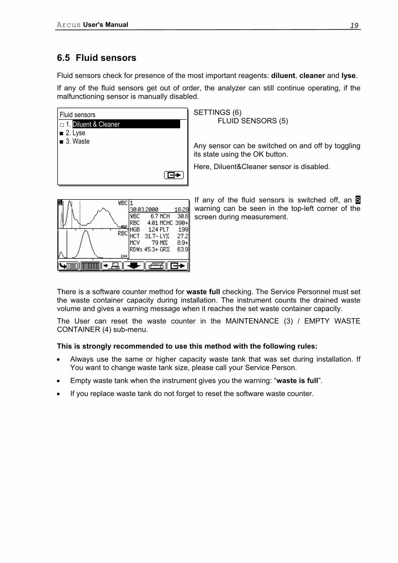
6.5 Fluid sensors
Fluid sensors check for presence of the most important reagents: diluent, cleaner and lyse.
If any of the fluid sensors get out of order, the analyzer can still continue operating, if the malfunctioning sensor is manually disabled.
SETTINGS (6) FLUID SENSORS (5)
Any sensor can be switched on and off by toggling its state using the OK button.
Here, Diluent&Cleaner sensor is disabled.
If any of the fluid sensors is switched off, an S warning can be seen in the top-left corner of the screen during measurement.
There is a software counter method for waste full checking. The Service Personnel must set the waste container capacity during installation. The instrument counts the drained waste volume and gives a warning message when it reaches the set waste container capacity.
The User can reset the waste counter in the MAINTENANCE (3) / EMPTY WASTE CONTAINER (4) sub-menu.
This is strongly recommended to use this method with the following rules:
• Always use the same or higher capacity waste tank that was set during installation. If You want to change waste tank size, please call your Service Person.
• Empty waste tank when the instrument gives you the warning: “waste is full”.
• If you replace waste tank do not forget to reset the software waste counter.
Fluid sensors □ 1. Diluent & Cleaner ■ 2. Lyse ■ 3. Waste
Diatron Ltd. 20
6.6 Printer settings The instrument supports the following printers or printer modes:
• HP DeskJet
• HP LaserJet
• Epson 9-pin
• Epson 24-pin
• Epson 24-pin in 9-pin mode
• Canon BJC
• Seiko DPU414
Any printer being able to emulate any of the above modes can be connected to the instrument.
To set up the instrument for your printer, go to the “Settings/Printer Settings” menu. Choose one of the possibilities using the up and down arrow keys within the text fields, and fill in the numerical fields using the numerical keys.
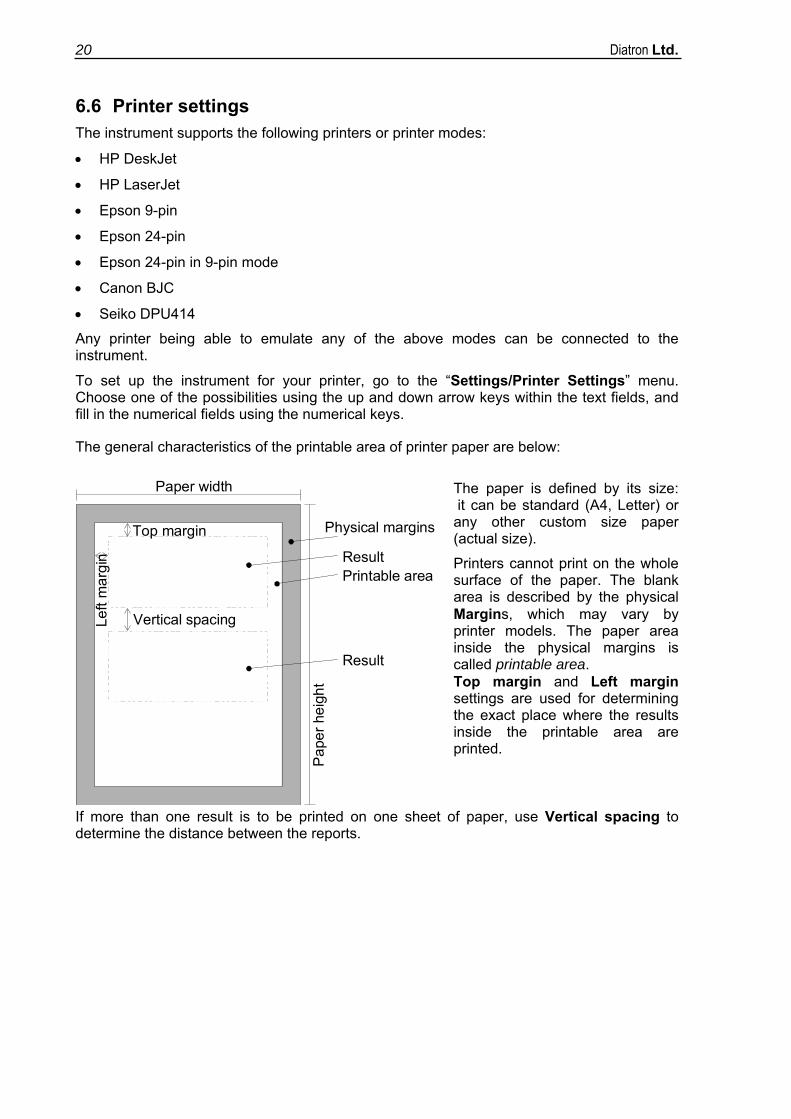
The general characteristics of the printable area of printer paper are below:
The paper is defined by its size: it can be standard (A4, Letter) or any other custom size paper (actual size).
Printers cannot print on the whole surface of the paper. The blank area is described by the physical Margins, which may vary by printer models. The paper area inside the physical margins is called printable area. Top margin and Left margin settings are used for determining the exact place where the results inside the printable area are printed.
If more than one result is to be printed on one sheet of paper, use Vertical spacing to determine the distance between the reports.
Paper width
Physical margins
ResultPrintable area
Top margin
Vertical spacingLeft
mar
gin
Result
Pap
er h
eigh
t
Arcus User's Manual 21
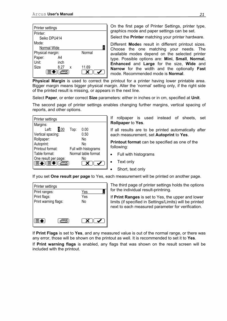
On the first page of Printer Settings, printer type, graphics mode and paper settings can be set. Select the Printer matching your printer hardware.
Different Modes result in different printout sizes. Choose the one matching your needs. The available modes depend on the selected printer type. Possible options are: Mini, Small, Normal, Enhanced and Large for the size, Wide and Narrow for the width and the optionally Fast mode. Recommended mode is Normal.
Physical Margin is used to correct the printout for a printer having lower printable area. Bigger margin means bigger physical margin. Alter the ‘normal’ setting only, if the right side of the printed result is missing, or appears in the next line.
Select Paper, or enter correct Size parameters: either in inches or in cm, specified at Unit. The second page of printer settings enables changing further margins, vertical spacing of reports, and other options.
If rollpaper is used instead of sheets, set Rollpaper to Yes.
If all results are to be printed automatically after each measurement, set Autoprint to Yes.
Printout format can be specified as one of the following:
• Full with histograms
• Text only
• Short, text only
If you set One result per page to Yes, each measurement will be printed on another page.
The third page of printer settings holds the options for the individual result-printning.
If Print Ranges is set to Yes, the upper and lower limits (if specified in Settings/Limits) will be printed next to each measured parameter for verification.
If Print Flags is set to Yes, and any measured value is out of the normal range, or there was any error, those will be shown on the printout as well. It is recommended to set it to Yes. If Print warning flags is enabled, any flags that was shown on the result screen will be included with the printout.
Printer settings Printer: Seiko DPU414 Mode: Normal Wide ↑ Physical margin: Normal Paper: A4 Unit: inch Size 8.27 x 11.69
Printer settings Margins: Left: 0.00 Top: 0.00 Vertical spacing: 0.50 Rollpaper: No Autoprint: No Printout format: Full with histograms Table format: Normal table format One result per page: No
Printer settings Print ranges: Yes ↓ Print flags: Yes Print warning flags: No

Diatron Ltd. 22
6.6.1 Troubleshooting guide for printing problems
Problem Possible reason, remedy Printer does not respond, no printout.
• Printer is off. Turn it on. • Printer is not connected to the analyzer.
Connect it to the parallel port at rear. • Printer is not On-line. Switch it to On-line mode. • Printer is out of paper. Feed the printer with paper.
Strange signs or letters appear on the printout.
• The selected printer type does not match your printer. Select the appropriate type in Printer Settings menu.
• Printer is not set up properly for HP or Epson (or compatible) mode. Modify the printer setup. Consult the printer’s manual
Right side of the printed report is missing, or appears in the next line.
• Decrease Margin settings in the Printer Settings menu. • Try selecting another Mode making a smaller printout.
The printed report is too small, there is a lot of space on the paper.
• Try selecting another Mode resulting in larger printout.
The end of the printout appears on the next page.
• Enter the correct Paper size. • Try increasing Margin.
It seems that one more patient report could fit on the same page.
• Enter the correct Paper size. • Try decreasing Margin, Top margin, Vertical spacing.
The printed result is not centered horizontally.
• Modify Left margin.
The printed result is not centered vertically.
• Modify Top margin.
The distance between two results is too small or too big.
• Modify Vertical spacing.
After printing, the printer does not eject the paper. But if you repeat printing, it appears in more copies.
• It is quite usual for bubble-jet or laser printers. Do not repeat printing. When the page is full, or you leave the actual menu, the printer will eject the paper automatically.
Arcus User's Manual 23
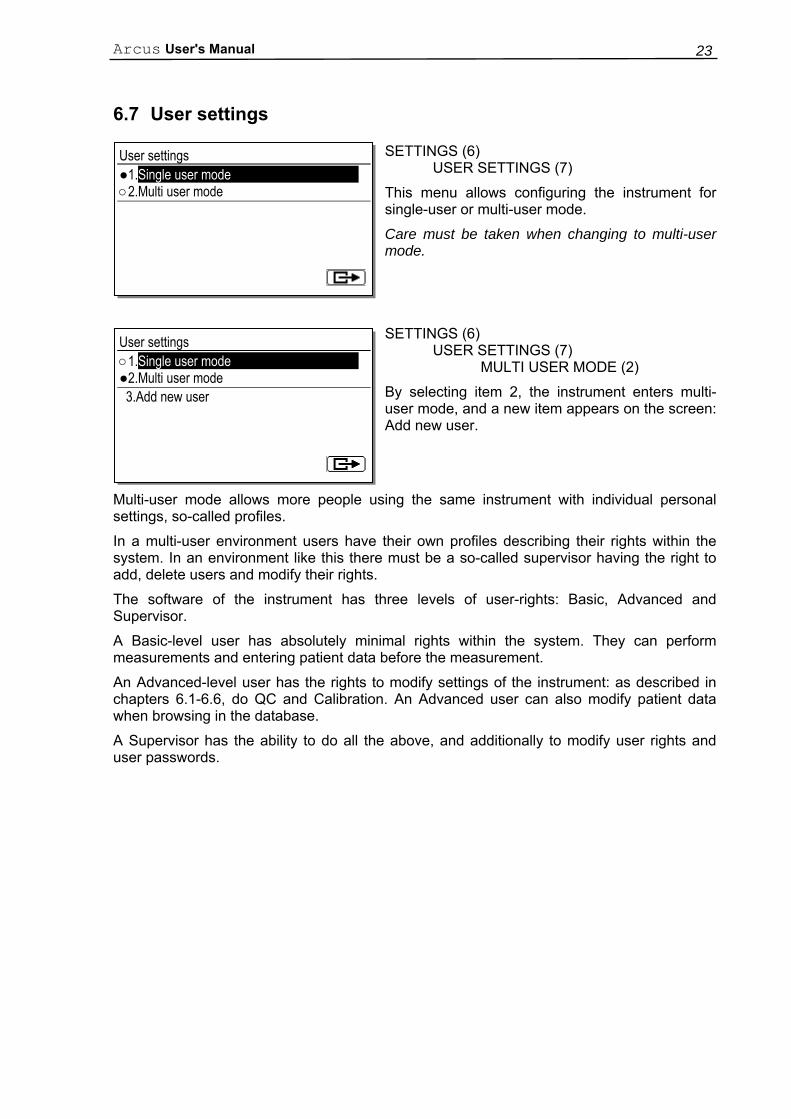
6.7 User settings
SETTINGS (6) USER SETTINGS (7)
This menu allows configuring the instrument for single-user or multi-user mode.
Care must be taken when changing to multi-user mode.
SETTINGS (6) USER SETTINGS (7) MULTI USER MODE (2)
By selecting item 2, the instrument enters multi-user mode, and a new item appears on the screen: Add new user.
Multi-user mode allows more people using the same instrument with individual personal settings, so-called profiles.
In a multi-user environment users have their own profiles describing their rights within the system. In an environment like this there must be a so-called supervisor having the right to add, delete users and modify their rights.
The software of the instrument has three levels of user-rights: Basic, Advanced and Supervisor.
A Basic-level user has absolutely minimal rights within the system. They can perform measurements and entering patient data before the measurement.
An Advanced-level user has the rights to modify settings of the instrument: as described in chapters 6.1-6.6, do QC and Calibration. An Advanced user can also modify patient data when browsing in the database.
A Supervisor has the ability to do all the above, and additionally to modify user rights and user passwords.
User settings ●1.Single user mode ○2.Multi user mode
User settings ○1.Single user mode ●2.Multi user mode 3.Add new user
Diatron Ltd. 24
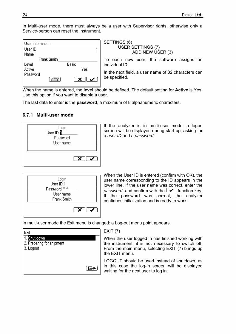
In Multi-user mode, there must always be a user with Supervisor rights, otherwise only a Service-person can reset the instrument.
SETTINGS (6) USER SETTINGS (7) ADD NEW USER (3)
To each new user, the software assigns an individual ID.
In the next field, a user name of 32 characters can be specified.
When the name is entered, the level should be defined. The default setting for Active is Yes. Use this option if you want to disable a user.
The last data to enter is the password, a maximum of 8 alphanumeric characters.
6.7.1 Multi-user mode
If the analyzer is in multi-user mode, a logon screen will be displayed during start-up, asking for a user ID and a password.
When the User ID is entered (confirm with OK), the user name corresponding to the ID appears in the lower line. If the user name was correct, enter the password, and confirm with the function key. If the password was correct, the analyzer continues initialization and is ready to work.
In multi-user mode the Exit menu is changed: a Log-out menu point appears.
EXIT (7)
When the user logged in has finished working with the instrument, it is not necessary to switch off. From the main menu, selecting EXIT (7) brings up the EXIT menu.
LOGOUT should be used instead of shutdown, as in this case the log-in screen will be displayed waiting for the next user to log in.
User information User ID 1 Name
Frank Smith____________________ Level Basic Active Yes Password
Login User ID 0________
Password User name
Login User ID 1
Password ****_____ User name Frank Smith
Exit 1. Shut down 2. Preparing for shipment 3. Logout
Arcus User's Manual 25
7. ROUTINE UTILIZATION
7.1 Measuring process
7.1.1 Sampling
The aspirating tip (a needle with rounded end) is used to draw sample from the tube containing the blood to be analyzed. It can not always be seen, as it has two positions:
a) Retracted position: inside the instrument (the status LED is either red, yellow or off).
b) Aspirating position: in front of the sampling bar; it can be activated only in certain menus associated directly with the sampling process; status LED is green.
1. Invert the closed sample tube 11 times to achieve a homogenous sample. Do not Shake!
2. Take off the cap of the sample tube.
3. Immerse the aspiration needle well into the sample.
4. Push the sampling bar or the START/OK button.
The instrument draws 25µl of sample, and the aspirating needle is retracted while its outer surface is automatically rinsed with diluent. This ensures a low carry-over between samples. Simultaneously, the status LED turns red.
During aspiration, hold the sampling tube in a stable position (for approx. 1 second) until you see the status LED flashing and hear the beeps indicating the end of the sampling process.
After these signals, you can remove and recap the sampling tube.
Make sure to immerse the sampling needle well into the sample, otherwise it can cause erroneous sampling, giving inaccurate results.
Important! When the needle stops for a while during its movement upwards, the needle must be out of the sample, otherwise the analyzer makes another aspiration in this state. This extra aspiration can also cause an inaccurate measurement.
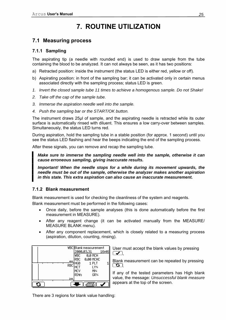
7.1.2 Blank measurement
Blank measurement is used for checking the cleanliness of the system and reagents. Blank measurement must be performed in the following cases:
• Once daily, before the sample analyses (this is done automatically before the first measurement in MEASURE).
• After any reagent change (it can be activated manually from the MEASURE/ MEASURE BLANK menu).
• After any component replacement, which is closely related to a measuring process (aspiration, dilution, counting, rinsing).
User must accept the blank values by pressing .
Blank measurement can be repeated by pressing .
If any of the tested parameters has High blank value, the message: Unsuccessful blank measure appears at the top of the screen.
There are 3 regions for blank value handling:
Diatron Ltd. 26
1. Optimal, all results are OK.
2. Blank is high, * flag is displayed at related parameter results.
3. Blank is too high, no result displayed in measurement mode.
Blank measurement ranges:
Parameter 1. No flag at parameter 2. * flag at result 3. E (error) flag at resultHGB 0-10 g/l 10-25 g/l > 25 g/l WBC 0 - 0.5 x10³ cells/µl 0.5-1.0 x10³ cells /µl > 1.0 x10³ cells /µl PLT 0 - 25 x103 cells /µl 25 - 50 x103 cells /µl > 50 x103 cells /µl RBC 0-0.05 x10⁶ cells/µl 0.05-0.5 x10⁶ cells /µl > 0.5 x10⁶ cells /µl
Accepted blank values are essential for proper calibration and QC measurement. For this reason, no calibration or QC measurement can be performed without accepted blank values.
Quality control (QC) measurement and Calibration can be performed only if all blank values are in the 1st region.
7.1.3 Calibration
Calibration is the procedure used to standardize the instrument by applying the necessary correction factors. Preferred hematology control is R&D Systems® CBC-3D Low, Normal and High.
It is recommended to do calibration in the following cases:
1. At analyzer installation, before beginning the analyses.
2. After replacing any component, related to the process of dilution or measurement.
3. When quality control measurements show any systematic error (bias) or they are outside predefined limits.
4. At regular time intervals (determined by the lab itself).
5. If you want to use the instrument in Prediluted mode.
Calibration can be performed in two ways:
1. User can enter calibration factors - without any calibration measurements – using the numerical keypad.
2. One-, two- or three-fold measurements of control or special calibrations material with known parameters. In this case, the instrument automatically calculates new factors using the following formula:
Assigned value x Stored factor New factor =
Measured value(s) (or average of those)
CAUTION! New calibration will invalidate the previous one. Old values cannot be retrieved, but can be reviewed in the VIEW CALIBRATIONS menu.
Arcus User's Manual 27
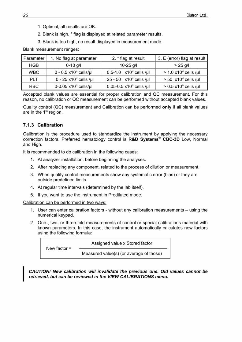
Calibration can be initiated by choosing Calibration in the Main Menu.
CALIBRATION (4)
Item 1 initiates calibration procedure.
Item 2 displays previous Calibrations
Item 3 opens calibration settings dialogue.
7.1.3.1 Factorial calibration If the CALIBRATION MODE has been previously set to Factorial Calibration, the factors can be set manually in the 0.80 - 1.20 range.
CALIBRATION (4) CALIBRATE (1) (factorial)
Set previously calculated factors using the numeric keys, confirm with OK.
Only parameters concerning the selected MCV, MPV / HCT, PCT mode are displayed.
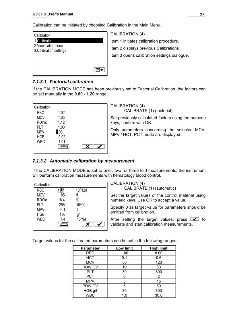
7.1.3.2 Automatic calibration by measurement
If the CALIBRATION MODE is set to one-, two- or three-fold measurements, the instrument will perform calibration measurements with hematology blood control.
CALIBRATION (4) CALIBRATE (1) (automatic)
Set the target values of the control material using numeric keys. Use OK to accept a value.
Specify 0 as target value for parameters should be omitted from calibration.
After setting the target values, press to validate and start calibration measurements.
Target values for the calibrated parameters can be set in the following ranges:
Parameter Low limit High limit RBC 1.00 8.00 HCT 0.1 0.6 MCV 50 120
RDW CV 10 50 PLT 30 800 PCT 0 2 MPV 5 15
PDW CV 5 50 HGB g/l 30 300
WBC 1.0 30.0
Calibration 1.Calibrate 2.View calibrations 3.Calibration settings
Calibration RBC 1.02 MCV 1.05 RDWc 1.12 PLT 1.00 MPV 1.00 HGB 0.92 WBC 1.01
Calibration RBC 4.57 10^12/l MCV 85 fl RDWc 16.4 % PLT 255 10^9/l MPV 9.1 fl HGB 136 g/l WBC 7.4 10^9/l
Diatron Ltd. 28
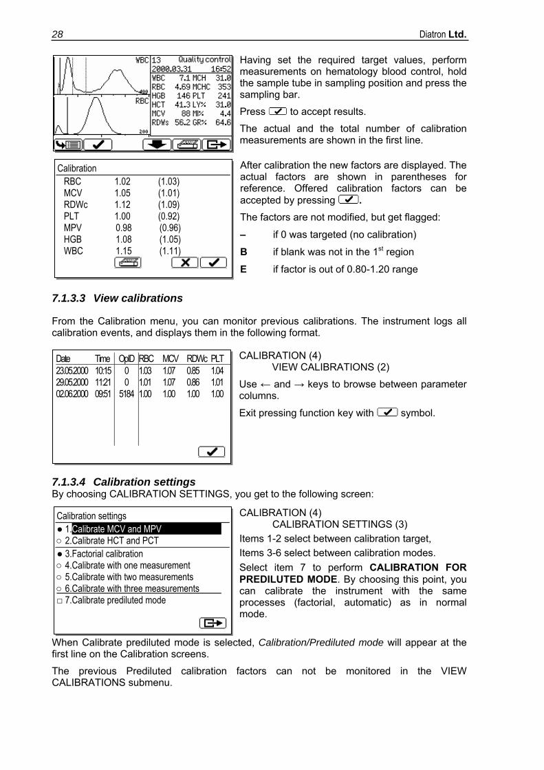
Having set the required target values, perform measurements on hematology blood control, hold the sample tube in sampling position and press the sampling bar.
Press to accept results. The actual and the total number of calibration measurements are shown in the first line.
After calibration the new factors are displayed. The actual factors are shown in parentheses for reference. Offered calibration factors can be accepted by pressing . The factors are not modified, but get flagged:
– if 0 was targeted (no calibration)
B if blank was not in the 1st region
E if factor is out of 0.80-1.20 range
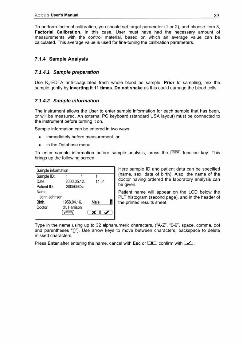
7.1.3.3 View calibrations
From the Calibration menu, you can monitor previous calibrations. The instrument logs all calibration events, and displays them in the following format.
CALIBRATION (4) VIEW CALIBRATIONS (2)
Use ← and → keys to browse between parameter columns.
Exit pressing function key with symbol.
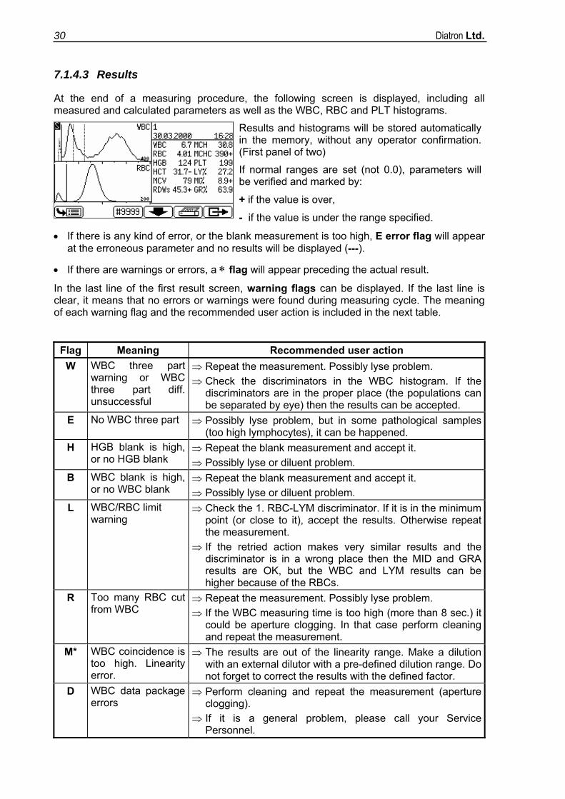
7.1.3.4 Calibration settings By choosing CALIBRATION SETTINGS, you get to the following screen:
CALIBRATION (4) CALIBRATION SETTINGS (3) Items 1-2 select between calibration target, Items 3-6 select between calibration modes. Select item 7 to perform CALIBRATION FOR PREDILUTED MODE. By choosing this point, you can calibrate the instrument with the same processes (factorial, automatic) as in normal mode.
When Calibrate prediluted mode is selected, Calibration/Prediluted mode will appear at the first line on the Calibration screens.
The previous Prediluted calibration factors can not be monitored in the VIEW CALIBRATIONS submenu.
Date Time OpID RBC MCV RDWc PLT 23.05.2000 10:15 0 1.03 1.07 0.85 1.04 29.05.2000 11:21 0 1.01 1.07 0.86 1.01 02.06.2000
09:51 5184 1.00 1.00 1.00 1.00
Calibration settings ● 1.Calibrate MCV and MPV ○ 2.Calibrate HCT and PCT ● 3.Factorial calibration ○ 4.Calibrate with one measurement ○ 5.Calibrate with two measurements ○ 6.Calibrate with three measurements □ 7.Calibrate prediluted mode
Calibration RBC 1.02 (1.03) MCV 1.05 (1.01) RDWc 1.12 (1.09) PLT 1.00 (0.92) MPV 0.98 (0.96) HGB 1.08 (1.05) WBC 1.15 (1.11)
Arcus User's Manual 29
To perform factorial calibration, you should set target parameter (1 or 2), and choose item 3, Factorial Calibration. In this case, User must have had the necessary amount of measurements with the control material, based on which an average value can be calculated. This average value is used for fine-tuning the calibration parameters.
7.1.4 Sample Analysis
7.1.4.1 Sample preparation
Use K3-EDTA anti-coagulated fresh whole blood as sample. Prior to sampling, mix the sample gently by inverting it 11 times. Do not shake as this could damage the blood cells.
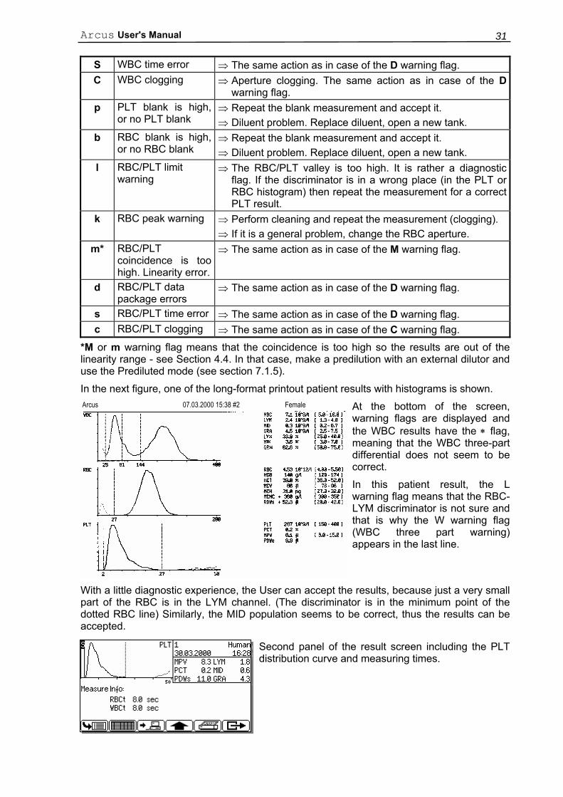
7.1.4.2 Sample information
The instrument allows the User to enter sample information for each sample that has been, or will be measured. An external PC keyboard (standard USA layout) must be connected to the instrument before turning it on.
Sample information can be entered in two ways:
• immediately before measurement, or
• in the Database menu
To enter sample information before sample analysis, press the function key. This brings up the following screen:
Here sample ID and patient data can be specified (name, sex, date of birth). Also, the name of the doctor having ordered the laboratory analysis can be given.
Patient name will appear on the LCD below the PLT histogram (second page), and in the header of the printed results sheet.
Type in the name using up to 32 alphanumeric characters, (“A-Z”, “0-9”, space, comma, dot and parentheses “()”). Use arrow keys to move between characters, backspace to delete missed characters.
Press Enter after entering the name, cancel with Esc or , confirm with .
Sample information Sample ID: 1 / 1 Date: 2000.05.12. 14:54 Patient ID: 20050502a Name: John Johnson Birth. 1958.04.16. Male ↓ Doctor: dr. Harrison
Diatron Ltd. 30
7.1.4.3 Results
At the end of a measuring procedure, the following screen is displayed, including all measured and calculated parameters as well as the WBC, RBC and PLT histograms.
Results and histograms will be stored automatically in the memory, without any operator confirmation. (First panel of two)
If normal ranges are set (not 0.0), parameters will be verified and marked by:
+ if the value is over,
- if the value is under the range specified.
• If there is any kind of error, or the blank measurement is too high, E error flag will appear at the erroneous parameter and no results will be displayed (---).
• If there are warnings or errors, a ∗ flag will appear preceding the actual result.
In the last line of the first result screen, warning flags can be displayed. If the last line is clear, it means that no errors or warnings were found during measuring cycle. The meaning of each warning flag and the recommended user action is included in the next table.
Flag Meaning Recommended user action W WBC three part
warning or WBC three part diff. unsuccessful
⇒ Repeat the measurement. Possibly lyse problem. ⇒ Check the discriminators in the WBC histogram. If the
discriminators are in the proper place (the populations can be separated by eye) then the results can be accepted.
E No WBC three part ⇒ Possibly lyse problem, but in some pathological samples (too high lymphocytes), it can be happened.
H HGB blank is high, or no HGB blank
⇒ Repeat the blank measurement and accept it. ⇒ Possibly lyse or diluent problem.
B WBC blank is high, or no WBC blank
⇒ Repeat the blank measurement and accept it. ⇒ Possibly lyse or diluent problem.
L WBC/RBC limit warning
⇒ Check the 1. RBC-LYM discriminator. If it is in the minimum point (or close to it), accept the results. Otherwise repeat the measurement.
⇒ If the retried action makes very similar results and the discriminator is in a wrong place then the MID and GRA results are OK, but the WBC and LYM results can be higher because of the RBCs.
R Too many RBC cut from WBC
⇒ Repeat the measurement. Possibly lyse problem. ⇒ If the WBC measuring time is too high (more than 8 sec.) it
could be aperture clogging. In that case perform cleaning and repeat the measurement.
M* WBC coincidence is too high. Linearity error.
⇒ The results are out of the linearity range. Make a dilution with an external dilutor with a pre-defined dilution range. Do not forget to correct the results with the defined factor.
D WBC data package errors
⇒ Perform cleaning and repeat the measurement (aperture clogging).
⇒ If it is a general problem, please call your Service Personnel.
Arcus User's Manual 31
S WBC time error ⇒ The same action as in case of the D warning flag. C WBC clogging ⇒ Aperture clogging. The same action as in case of the D
warning flag. p PLT blank is high,
or no PLT blank ⇒ Repeat the blank measurement and accept it. ⇒ Diluent problem. Replace diluent, open a new tank.
b RBC blank is high, or no RBC blank
⇒ Repeat the blank measurement and accept it. ⇒ Diluent problem. Replace diluent, open a new tank.
l RBC/PLT limit warning
⇒ The RBC/PLT valley is too high. It is rather a diagnostic flag. If the discriminator is in a wrong place (in the PLT or RBC histogram) then repeat the measurement for a correct PLT result.
k RBC peak warning ⇒ Perform cleaning and repeat the measurement (clogging). ⇒ If it is a general problem, change the RBC aperture.
m* RBC/PLT coincidence is too high. Linearity error.
⇒ The same action as in case of the M warning flag.
d RBC/PLT data package errors
⇒ The same action as in case of the D warning flag.
s RBC/PLT time error ⇒ The same action as in case of the D warning flag. c RBC/PLT clogging ⇒ The same action as in case of the C warning flag.
*M or m warning flag means that the coincidence is too high so the results are out of the linearity range - see Section 4.4. In that case, make a predilution with an external dilutor and use the Prediluted mode (see section 7.1.5).
In the next figure, one of the long-format printout patient results with histograms is shown. Arcus 07.03.2000 15:38 #2 Female At the bottom of the screen,
warning flags are displayed and the WBC results have the ∗ flag, meaning that the WBC three-part differential does not seem to be correct. In this patient result, the L warning flag means that the RBC-LYM discriminator is not sure and that is why the W warning flag (WBC three part warning) appears in the last line.
With a little diagnostic experience, the User can accept the results, because just a very small part of the RBC is in the LYM channel. (The discriminator is in the minimum point of the dotted RBC line) Similarly, the MID population seems to be correct, thus the results can be accepted.
Second panel of the result screen including the PLT distribution curve and measuring times.
Diatron Ltd. 32
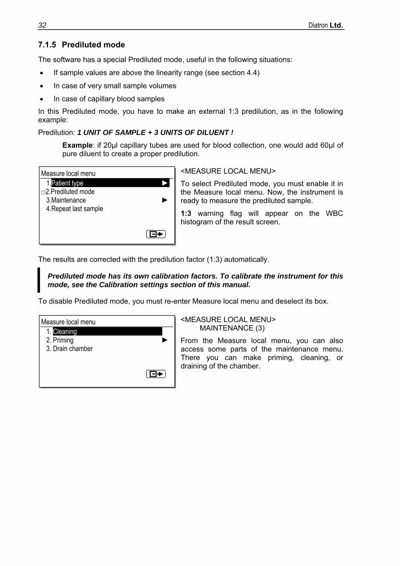
7.1.5 Prediluted mode
The software has a special Prediluted mode, useful in the following situations:
• If sample values are above the linearity range (see section 4.4)
• In case of very small sample volumes
• In case of capillary blood samples
In this Prediluted mode, you have to make an external 1:3 predilution, as in the following example:
Predilution: 1 UNIT OF SAMPLE + 3 UNITS OF DILUENT !
Example: if 20µl capillary tubes are used for blood collection, one would add 60µl of pure diluent to create a proper predilution.
<MEASURE LOCAL MENU>
To select Prediluted mode, you must enable it in the Measure local menu. Now, the instrument is ready to measure the prediluted sample.
1:3 warning flag will appear on the WBC histogram of the result screen.
The results are corrected with the predilution factor (1:3) automatically.
Prediluted mode has its own calibration factors. To calibrate the instrument for this mode, see the Calibration settings section of this manual.
To disable Prediluted mode, you must re-enter Measure local menu and deselect its box.
<MEASURE LOCAL MENU> MAINTENANCE (3)
From the Measure local menu, you can also access some parts of the maintenance menu. There you can make priming, cleaning, or draining of the chamber.
Measure local menu 1.Patient type ► □2.Prediluted mode 3.Maintenance ► 4.Repeat last sample
Measure local menu 1. Cleaning 2. Priming ► 3. Drain chamber

Arcus User's Manual 33
7.2 Quality control
By measuring control materials, day-to-day reproducibility can be monitored. In this submenu, both target value and acceptable ranges for each parameter can be determined for the different QC levels.
Arcus provides six different Quality Control profiles, so-called levels. You can set up six individual reference sheets for each control material (e.g. low, normal and high control blood). QC measurement results will be added to the selected level, is indicated at the top right corner.
The target values of the control material should be set only once, at the beginning of the QC measurements. Resetting parameters deletes previous QC results of the active level.
CAUTION! Any change in the QC material setting deletes previous QC results, therefore it is strongly recommended to have them printed out before making any changes to parameters.
QUALITY CONTROL (6) This menu allows setting and monitoring data related to the QC procedure. Use commercially available control material. The preparation and measurement process is the same as with patient samples.
QUALITY CONTROL (6) SET QC LEVEL (5)
Select the level you wish to use.
The active level is displayed in the top right corner on QC related screens.
QUALITY CONTROL (5) SET QC REFERENCE (1) Both target values and acceptable ranges can be specified. Only the parameters displayed on these screens can be specified. Modify displayed values using the numerical keyboard. Pressing the OK button validates values. To move on to further parameters, press the page down function key.
Quality control measurements can only be made after an optimal blank measurement result has been accepted (all parameters were in the 1st range).
Quality control 1.Set QC reference 2.QC measure 3.View table of QC measures 4.View QC diagram 5.Set QC level ►
Actual QC level: 1
Set QC level ●1. QC Level 1 ○2. QC Level 2 ○3. QC Level 3 ○4. QC Level 4 ○5. QC Level 5 ○6. QC Level 6
QC reference values QC Level: 1 LOT No.: __________________ Exp. date: 12.05.2001. WBC 5.5 - 19.5 10^9/l RBC 5.00 - 10.00 10^12/l HGB 80 - 150 g/l HCT 24.0 - 45.0 % MCV 39 - 55 fl
Diatron Ltd. 34
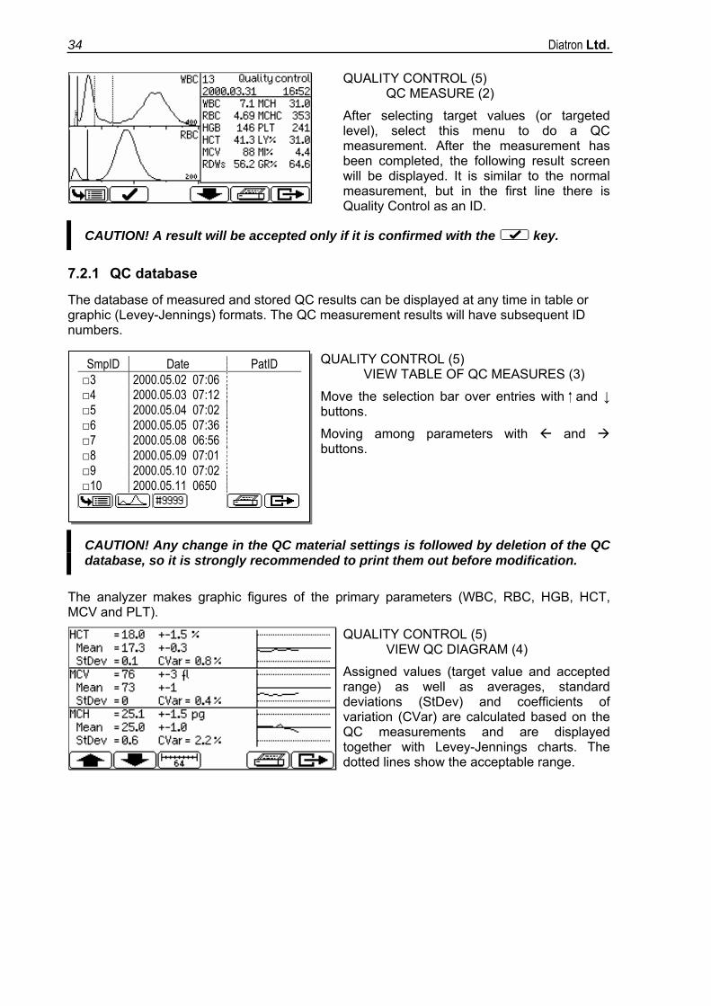
QUALITY CONTROL (5) QC MEASURE (2)
After selecting target values (or targeted level), select this menu to do a QC measurement. After the measurement has been completed, the following result screen will be displayed. It is similar to the normal measurement, but in the first line there is Quality Control as an ID.
CAUTION! A result will be accepted only if it is confirmed with the key.
7.2.1 QC database
The database of measured and stored QC results can be displayed at any time in table or graphic (Levey-Jennings) formats. The QC measurement results will have subsequent ID numbers.
QUALITY CONTROL (5) VIEW TABLE OF QC MEASURES (3)
Move the selection bar over entries with and ↓ buttons.
Moving among parameters with and buttons.
CAUTION! Any change in the QC material settings is followed by deletion of the QC database, so it is strongly recommended to print them out before modification.
The analyzer makes graphic figures of the primary parameters (WBC, RBC, HGB, HCT, MCV and PLT).
QUALITY CONTROL (5) VIEW QC DIAGRAM (4)
Assigned values (target value and accepted range) as well as averages, standard deviations (StDev) and coefficients of variation (CVar) are calculated based on the QC measurements and are displayed together with Levey-Jennings charts. The dotted lines show the acceptable range.
SmpID Date PatID □3 2000.05.02 07:06 □4 2000.05.03 07:12 □5 2000.05.04 07:02 □6 2000.05.05 07:36 □7 2000.05.08 06:56 □8 2000.05.09 07:01 □9 2000.05.10 07:02 □10 2000.05.11 0650
Arcus User's Manual 35
7.3 Auto stand-by
In measurement mode, the analyzer will automatically go to stand-by if it is left alone - without starting any new measurement - for more than 15 minutes. While in stand-by, the aspirating tip is inside the analyzer and the chamber is filled with diluent. When the sampling bar is pressed, the chamber will be cleaned, the tip comes out and the analyzer is ready for the next measurement. The same process is performed when entering and leaving measurement mode.
7.4 Printouts When required, the following items can be sent to an external printer by pressing the function key button.
• Database result(s) (table format).
• Database (specified patient results with histograms).
• QC result (Levey-Jennings chart).
• QC result(s) (table format).
• Last measured blank result.
• Last measured patient result (with histograms).
• Last measured QC result.
• Device Information and Device Statistics.
• Self test result.
• Set parameters.
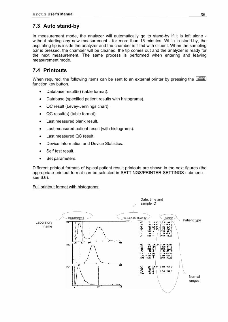
Different printout formats of typical patient-result printouts are shown in the next figures (the appropriate printout format can be selected in SETTINGS/PRINTER SETTINGS submenu – see 6.6).
Full printout format with histograms:
Laboratory name
Date, time and sample ID
Patient type
Normal ranges
Hematology-1 07.03.2000 15:38 #2 Female
Diatron Ltd. 36
In this printout normal ranges (limits), flags and warning flags are all enabled. The printing modes of these parameters can be selected within PRINTER SETTINGS submenu.
If normal ranges are set, flags are enabled, and patient values are over or below the limits specified, the result out of the range is marked with an +/- mark.
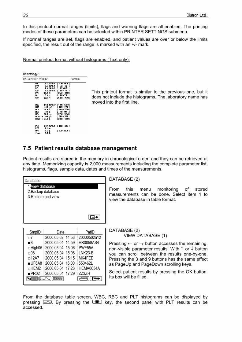
Normal printout format without histograms (Text only):
Hematology-1 07.03.2000 15:38 #2 Female
This printout format is similar to the previous one, but it does not include the histograms. The laboratory name has moved into the first line.
7.5 Patient results database management
Patient results are stored in the memory in chronological order, and they can be retrieved at any time. Memorizing capacity is 2,000 measurements including the complete parameter list, histograms, flags, sample data, dates and times of the measurements.
DATABASE (2)
From this menu monitoring of stored measurements can be done. Select item 1 to view the database in table format.
DATABASE (2) VIEW DATABASE (1)
Pressing ← or → button accesses the remaining, non-visible parameter results. With ↑ or ↓ button you can scroll between the results one-by-one. Pressing the 3 and 9 buttons has the same effect as PageUp and PageDown scrolling keys.
Select patient results by pressing the OK button. Its box will be filled.
From the database table screen, WBC, RBC and PLT histograms can be displayed by pressing . By pressing the key, the second panel with PLT results can be accessed.
Database 1.View database 2.Backup database 3.Restore and view
SmpID Date PatID □7 2000.05.02 14:56 20000502a12 ■8 2000.05.04 14:59 HR0058AS4 □High05 2000.05.04 15:06 PWF55A □08 2000.05.04 15:08 LNK23-B □12A7 2000.05.04 15:15 MK4FED ■UF6A8 2000.05.04 16:00 550462L □HEM2 2000.05.04 17:26 HEMA0034A ■PR02 2000.05.04 17:29 ZZ3ZH
Arcus User's Manual 37
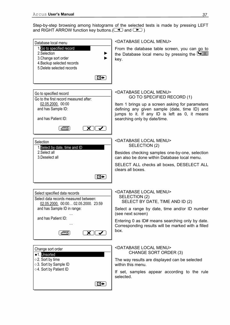
Step-by-step browsing among histograms of the selected tests is made by pressing LEFT and RIGHT ARROW function key buttons.( and )
<DATABASE LOCAL MENU>
From the database table screen, you can go to the Database local menu by pressing the key.
<DATABASE LOCAL MENU> GO TO SPECIFIED RECORD (1)
Item 1 brings up a screen asking for parameters defining any given sample (date, time ID) and jumps to it. If any ID is left as 0, it means searching only by date/time.
<DATABASE LOCAL MENU> SELECTION (2)
Besides checking samples one-by-one, selection can also be done within Database local menu.
SELECT ALL checks all boxes, DESELECT ALL clears all boxes.
<DATABASE LOCAL MENU> SELECTION (2) SELECT BY DATE, TIME AND ID (2)
Select a range by date, time and/or ID number (see next screen)
Entering 0 as ID# means searching only by date. Corresponding results will be marked with a filled box.
<DATABASE LOCAL MENU> CHANGE SORT ORDER (3)
The way results are displayed can be selected within this menu.
If set, samples appear according to the rule selected.
Database local menu 1.Go to specified record 2.Selection ► 3.Change sort order ► 4.Backup selected records 5.Delete selected records
Go to specified record Go to the first record measured after:
02.05.2000. 00:00 and has Sample ID: and has Patient ID:
Selection 1.Select by date, time and ID 2.Select all 3.Deselect all
Select specified data records Select data records measured between:
02.05.2000. 00:00… 02.05.2000. 23:59 and has Sample ID in range: … and has Patient ID: …
Change sort order ●1. Unsorted ○2. Sort by time ○3. Sort by Sample ID ○4. Sort by Patient ID
Diatron Ltd. 38
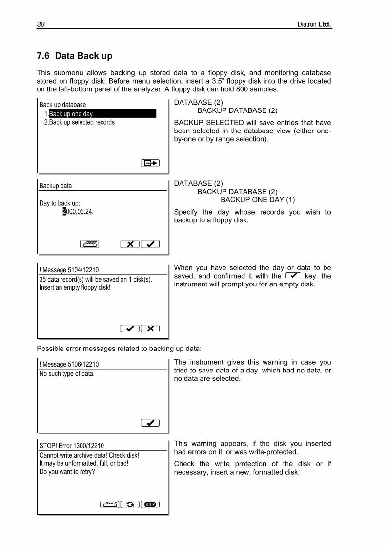
7.6 Data Back up
This submenu allows backing up stored data to a floppy disk, and monitoring database stored on floppy disk. Before menu selection, insert a 3.5” floppy disk into the drive located on the left-bottom panel of the analyzer. A floppy disk can hold 800 samples.
DATABASE (2) BACKUP DATABASE (2)
BACKUP SELECTED will save entries that have been selected in the database view (either one-by-one or by range selection).
DATABASE (2) BACKUP DATABASE (2) BACKUP ONE DAY (1)
Specify the day whose records you wish to backup to a floppy disk.
When you have selected the day or data to be saved, and confirmed it with the key, the instrument will prompt you for an empty disk.
Possible error messages related to backing up data:
The instrument gives this warning in case you tried to save data of a day, which had no data, or no data are selected.
This warning appears, if the disk you inserted had errors on it, or was write-protected.
Check the write protection of the disk or if necessary, insert a new, formatted disk.
Back up database 1.Back up one day 2.Back up selected records
Backup data Day to back up:
2000.05.24.
! Message 5104/12210 35 data record(s) will be saved on 1 disk(s). Insert an empty floppy disk!
! Message 5106/12210 No such type of data.
STOP! Error 1300/12210 Cannot write archive data! Check disk! It may be unformatted, full, or bad! Do you want to retry?
Arcus User's Manual 39
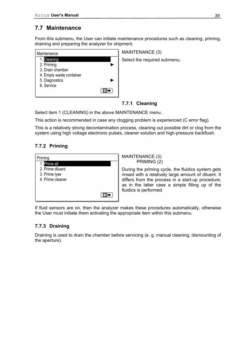
7.7 Maintenance
From this submenu, the User can initiate maintenance procedures such as cleaning, priming, draining and preparing the analyzer for shipment.
MAINTENANCE (3)
Select the required submenu.
7.7.1 Cleaning
Select item 1 (CLEANING) in the above MAINTENANCE menu.
This action is recommended in case any clogging problem is experienced (C error flag).
This is a relatively strong decontamination process, cleaning out possible dirt or clog from the system using high voltage electronic pulses, cleaner solution and high-pressure backflush.
7.7.2 Priming
MAINTENANCE (3) PRIMING (2)
During the priming cycle, the fluidics system gets rinsed with a relatively large amount of diluent. It differs from the process in a start-up procedure; as in the latter case a simple filling up of the fluidics is performed.
If fluid sensors are on, then the analyzer makes these procedures automatically, otherwise the User must initiate them activating the appropriate item within this submenu.
7.7.3 Draining
Draining is used to drain the chamber before servicing (e. g. manual cleaning, dismounting of the aperture).
Maintenance 1. Cleaning 2. Priming ► 3. Drain chamber 4. Empty waste container 5. Diagnostics ► 6. Service
Priming 1. Prime all 2. Prime diluent 3. Prime lyse 4. Prime cleaner
Diatron Ltd. 40
7.7.4 Manual cleaning of the aperture The risk of clogging of the aperture by protein build-up is held at a minimum level in several ways. These are as follows:
• The specific cleaning cycle can be executed from MAINTENANCE/CLEANING submenu.
• Aspiration of the specific cleaner as patient sample. • Applying high-voltage electric impulses to the aperture.
(Done after each measurement.)
If manual cleaning of the aperture is required, instructions listed below should be followed:
1. Drain the chamber: MAINTENANCE/DRAIN 2. Open the side door (right side). 3. Remove the reference electrode connection and the U-shaped metal fixing. 4. Remove the aperture assembly from the measuring chamber. 5. Pull out the measuring tube from the part containing the electrode. 6. Cleaning of the aperture can be performed by placing it into a 10% hypochlorite
solution, or into an ultrasonic cleaning bath for approximately 1 minute. 7. Rinse well with distilled water. 8. Put back the measuring tube to the electrode holding part, and the U-shaped metal
fixing. 9. Install the aperture in the measuring chamber, and connect the reference electrode. 10. Execute a priming cycle. 11. Measure blank until you reach acceptable blank results.
7.7.5 Weekly maintenance
User should do weekly maintenance on the first workday, before starting up the analyzer.
7.7.5.1 Cleaning washing head
There could be salt build-up in the lower surface of the washing head, which may cause malfunction during operation. User should clean the lower surface of the aspirating tip cleaning head using a soft cloth immersed in warm tap water to remove salt build-up.
See steps 1 and 2 below: 1. Exit Measurement menu and wait until needle stops, then open side door. 2. To clean, gently rub the lower surface of the washing head, then close the side door.
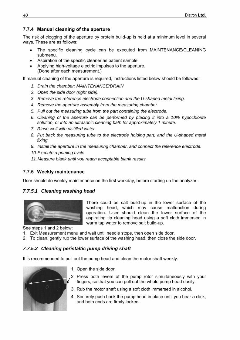
7.7.5.2 Cleaning peristaltic pump driving shaft
It is recommended to pull out the pump head and clean the motor shaft weekly.
1. Open the side door.
2. Press both levers of the pump rotor simultaneously with your fingers, so that you can pull out the whole pump head easily.
3. Rub the motor shaft using a soft cloth immersed in alcohol.
4. Securely push back the pump head in place until you hear a click, and both ends are firmly locked.
Arcus User's Manual 41
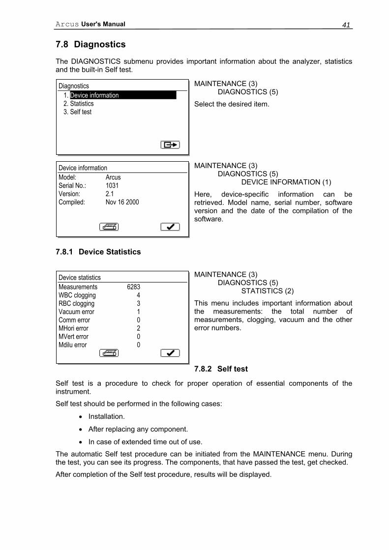
7.8 Diagnostics
The DIAGNOSTICS submenu provides important information about the analyzer, statistics and the built-in Self test.
MAINTENANCE (3) DIAGNOSTICS (5)
Select the desired item.
MAINTENANCE (3) DIAGNOSTICS (5) DEVICE INFORMATION (1)
Here, device-specific information can be retrieved. Model name, serial number, software version and the date of the compilation of the software.
7.8.1 Device Statistics
MAINTENANCE (3) DIAGNOSTICS (5) STATISTICS (2)
This menu includes important information about the measurements: the total number of measurements, clogging, vacuum and the other error numbers.
7.8.2 Self test
Self test is a procedure to check for proper operation of essential components of the instrument.
Self test should be performed in the following cases:
• Installation.
• After replacing any component.
• In case of extended time out of use.
The automatic Self test procedure can be initiated from the MAINTENANCE menu. During the test, you can see its progress. The components, that have passed the test, get checked.
After completion of the Self test procedure, results will be displayed.
Diagnostics 1. Device information 2. Statistics 3. Self test
Device information Model: Arcus Serial No.: 1031 Version: 2.1 Compiled: Nov 16 2000
Device statistics Measurements 6283 WBC clogging 4 RBC clogging 3 Vacuum error 1 Comm error 0 MHori error 2 MVert error 0 Mdilu error 0
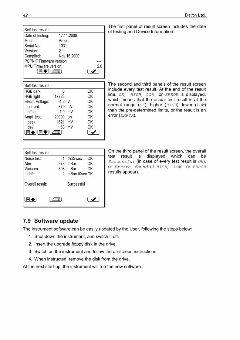
Diatron Ltd. 42
The first panel of result screen includes the date of testing and Device Information. The second and third panels of the result screen include every test result. At the end of the result line, OK, HIGH, LOW, or ERROR is displayed, which means that the actual test result is at the normal range (OK), higher (HIGH), lower (LOW) than the pre-determined limits, or the result is an error (ERROR).
On the third panel of the result screen, the overall test result is displayed which can be Successful (in case of every test result is OK), or Errors found (if HIGH, LOW or ERROR results appear).
7.9 Software update The instrument software can be easily updated by the User, following the steps below:
1. Shut down the instrument, and switch it off.
2. Insert the upgrade floppy disk in the drive.
3. Switch on the instrument and follow the on-screen instructions.
4. When instructed, remove the disk from the drive.
At the next start-up, the instrument will run the new software.
Self test results Date of testing: 17.11.2000 Model: Arcus Serial No: 1031 Version: 2.1 Compiled: Nov 16 2000 PCPNIF Firmware version --- MPU Firmware version: 2.0
Self test results HGB dark: 0 OK HGB light 17723 OK Electr. Voltage: 51.2 V OK current: 879 uA OK offset -1.9 mV OK Ampl. test: 20000 pls OK peak: 1621 mV OK dev: 53 mV OK
Self test results Noise test: 1 pls/5 sec OK Atm 978 mBar OK Vacuum: 308 mBar OK drift: 2 mBar/10sec OK Overall result: Successful

Arcus User's Manual 43
8. APPENDIX "A": REAGENT SOLUTIONS AND CONSUMPTION
Reagents supplied by Diatron® are the only ones recommended for use with the analyzer.
1. Diluent: An isotonic saline solution used to dilute whole blood specimens and to rinse the fluidic system between measuring procedures.
Diaton MCDiff-16 Ordering No.: 18111 (5 liters), 18101 (20 liters)
2. Lysing reagent: Used to prepare blood hemolysate for WBC and HGB measurement.
Abalyse Ordering No.: 28112 (1 liter), 28102 (5 liters)
3. Cleaner: Used to perform cleaning process of the fluidics.
Abaclean Ordering No.: 28113 (1 liter), 28103 (5 liters)
Average reagent consumption of Arcus (software: V2.1):
Number of daily measurements
Diluent ml/test
Lyse ml/test
Cleaner ml/test
1 259 15 16
2 146 7,7 8,6
5 79 3,6 4,0
10 56 2,3 2,5
20 45 1,6 1,8
50 39 1,2 1,3
100 36 1,0 1,2
Diatron Ltd. 44
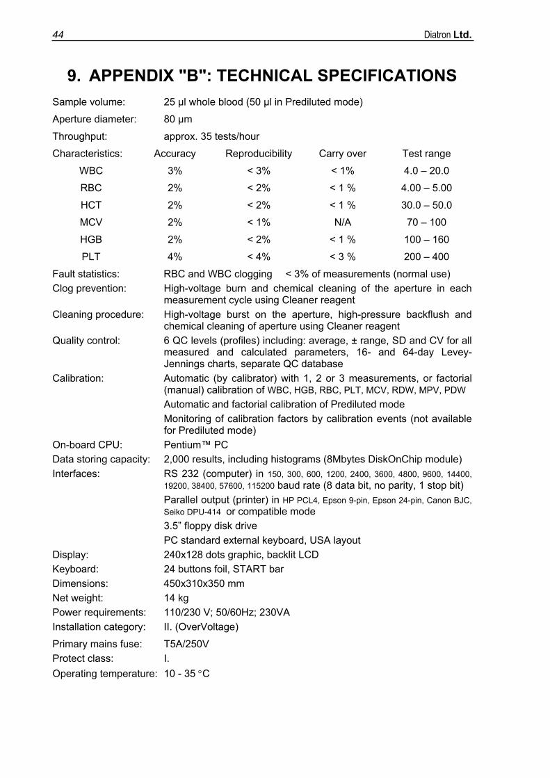
9. APPENDIX "B": TECHNICAL SPECIFICATIONS Sample volume: 25 µl whole blood (50 µl in Prediluted mode)
Aperture diameter: 80 µm
Throughput: approx. 35 tests/hour
Characteristics: Accuracy Reproducibility Carry over Test range
WBC 3% < 3% < 1% 4.0 – 20.0
RBC 2% < 2% < 1 % 4.00 – 5.00
HCT 2% < 2% < 1 % 30.0 – 50.0
MCV 2% < 1% N/A 70 – 100
HGB 2% < 2% < 1 % 100 – 160
PLT 4% < 4% < 3 % 200 – 400
Fault statistics: RBC and WBC clogging < 3% of measurements (normal use) Clog prevention: High-voltage burn and chemical cleaning of the aperture in each
measurement cycle using Cleaner reagent Cleaning procedure: High-voltage burst on the aperture, high-pressure backflush and
chemical cleaning of aperture using Cleaner reagent Quality control: 6 QC levels (profiles) including: average, ± range, SD and CV for all
measured and calculated parameters, 16- and 64-day Levey-Jennings charts, separate QC database
Calibration: Automatic (by calibrator) with 1, 2 or 3 measurements, or factorial (manual) calibration of WBC, HGB, RBC, PLT, MCV, RDW, MPV, PDW
Automatic and factorial calibration of Prediluted mode Monitoring of calibration factors by calibration events (not available
for Prediluted mode) On-board CPU: Pentium™ PC Data storing capacity: 2,000 results, including histograms (8Mbytes DiskOnChip module) Interfaces: RS 232 (computer) in 150, 300, 600, 1200, 2400, 3600, 4800, 9600, 14400,
19200, 38400, 57600, 115200 baud rate (8 data bit, no parity, 1 stop bit) Parallel output (printer) in HP PCL4, Epson 9-pin, Epson 24-pin, Canon BJC, Seiko DPU-414 or compatible mode 3.5” floppy disk drive
PC standard external keyboard, USA layout Display: 240x128 dots graphic, backlit LCD Keyboard: 24 buttons foil, START bar Dimensions: 450x310x350 mm Net weight: 14 kg Power requirements: 110/230 V; 50/60Hz; 230VA Installation category: II. (OverVoltage)
Primary mains fuse: T5A/250V Protect class: I. Operating temperature: 10 - 35 °C
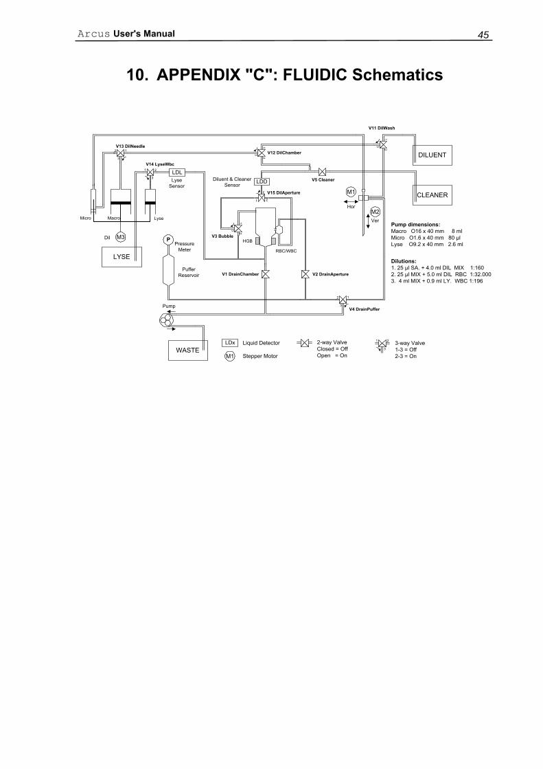
Arcus User's Manual 45
10. APPENDIX "C": FLUIDIC Schematics
HGB
WASTE
CLEANER
M3
M2
M1
LYSE
P
V13 DilNeedle
V14 LyseWbc
V5 Cleaner
V15 DilAperture
V2 DrainApertureV1 DrainChamber
V12 DilChamber
RBC/WBC
V4 DrainPuffer
DILUENT
V11 DilWash
M1
LDx Liquid Detector
Stepper Motor
2-way ValveClosed = OffOpen = On
1 2
33-way Valve1-3 = Off2-3 = On
Pump dimensions:Macro O16 x 40 mm 8 mlMicro O1.6 x 40 mm 80 µlLyse O9.2 x 40 mm 2.6 ml
12
3
1 2
3
12
3
12
3
12
3
Dilutions:1. 25 µl SA. + 4.0 ml DIL MIX 1:1602. 25 µl MIX + 5.0 ml DIL RBC 1:32.0003. 4 ml MIX + 0.9 ml LY. WBC 1:196
Micro Macro Lyse
Pump
Dil
Hor
Ver
1 2
3
PufferReservoir
PressureMeter
LyseSensor
Diluent & CleanerSensor
12
3
LDL
LDD
V3 Bubble
Diatron Ltd. 46
11. APPENDIX "D": ACCESSORIES
This appendix includes the contents of Diatron® Arcus pack:
• Arcus Hematology Analyzer.
• Arcus User's Manual.
• Arcus Reagent Tubes (marked with colours) :
- Diluent tube (green)
- Lyse tube (yellow)
- Clean tube (blue)
- Waste tube (red)
• Arcus Cleaning Tube Kit:
• Arcus Caps for reagent containers (Marked with the same colors as the Reagent Tubes).
• Arcus Power cable.
• Arcus Spare Part: Pump rotor.
Diluent Lyse Clean