die temperature control fitting series - microsoft · die temperature control minimal series stop...
TRANSCRIPT

244
http://www.pisco.co.jp
Die TemperatureControl
MinimalSeries
Stop FittingSeries
RotarySeries
Twist-ProofFitting
Block andConnector
Coupling
ColorCap
FITTING
TUBE
VALVE
CONTROLLERMAKE-TO-ORDERPRODUCTS
Push-In Fitting Type Molding Die Temperature Control CouplingDie Temperature Control Fitting Series
●Push-In Fitting Type for Die Temperature Control.
●Thermal Oil, Clean Water and Air for Fluid Medium.
●No Projection left on the die, after uncoupling Plug.
●Stop Valve Built-In Type prevents Hot Water Ejection when uncoupling Plug.

Fitting SeriesDie Temperature Control Fitting Series
Die TemperatureControl
245
Anti-spatter& Brass Series
EGSeries
PPSeries
ChemicalSeries
StainlessSeries
MiniSeries
StandardSeries
FITT
ING ■ Model Designation (Example)
④ Tube dia. / Inner thread(No code: Thread part (socket) only)
⑤ Thread size(No code: Fittng part (plug) only)Thread size Taper pipe thread
Code 01 02 03 04Size R1/8 R1/4 R3/8 R1/2
② Fitting Type(No code: Thread part (socket) only) C:Straight L:Elbow
Tube dia. Tube O.D. mm Tube I.D. inch Inner thread
Code 6 8 10 12 ID06B ID09B 01F 02F 03FSize ø6 ø8 ø10 ø12 1/4 3/8 Rc1/8 Rc1/4 Rc3/8
CAK 10 10
①Type
②Fitting Type
③Connection size
④Tube dia. / Inner thread
03
⑥Parts
⑤Thread size
⑥ Parts No code:Plug and Socket P:Plug S:Socket (Thread part only)
① Type AK:Without stop valve (Standard type) AS:With stop valve
③ Connection size 08:08 series (Standard type only) 10:10 series

246
http://www.pisco.co.jp
Die TemperatureControl
MinimalSeries
Stop FittingSeries
RotarySeries
Twist-ProofFitting
Block andConnector
Coupling
ColorCap
FITTING
TUBE
VALVE
CONTROLLERMAKE-TO-ORDERPRODUCTS
■ Specifications
■ Construction (Elbow: AKL)
※ . Make sure to follow the instructions below when the fluid medium is water or heat medium oil.1. Surge pressure must be controlled lower than max. operating pressure when using water or
heat medium oil.2. Be sure to place Insert Ring into the tube edge when using water or heat medium oil.
Warning
Elastic sleeve (HNBR)
Tube
Release ring (POM)
Lock-claws (Stainless steel)
Tube End
Thread body (Nickel-plated brass)
Guide ring (Nickel-plated brass)
Fluid medium Air Water (Clean water ※ ) Heat medium oil (※ )
Max. operating pressure 0.9MPa
Max. vacuum -100kPa -Operating temp. range 0~60℃ (No freezing) 0~99℃ (No freezing) 0~120℃ (No freezing)
Sleeve (Nickel-plated brass)
O-ring (HNBR)
Heat-proof Sealock coating
Collet (Nickel-plated brass)
Plug body (Nickel-plated brass)
Fitting body (Nickel-plated brass)
Fitting SeriesDie Temperature Control Fitting Series
Die TemperatureControl
247
Anti-spatter& Brass Series
EGSeries
PPSeries
ChemicalSeries
StainlessSeries
MiniSeries
StandardSeries
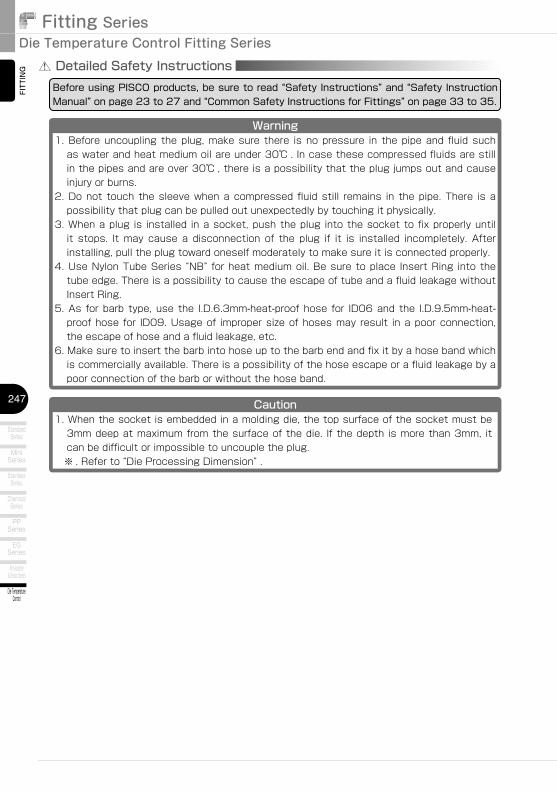
FITTING Detailed Safety Instructions
Before using PISCO products, be sure to read “Safety Instructions” and “Safety Instruction Manual” on page 23 to 27 and “Common Safety Instructions for Fittings” on page 33 to 35.
Warning1. Before uncoupling the plug, make sure there is no pressure in the pipe and fluid such
as water and heat medium oil are under 30℃ . In case these compressed fluids are still in the pipes and are over 30℃ , there is a possibility that the plug jumps out and cause injury or burns.
2. Do not touch the sleeve when a compressed fluid still remains in the pipe. There is a possibility that plug can be pulled out unexpectedly by touching it physically.
3. When a plug is installed in a socket, push the plug into the socket to fix properly until it stops. It may cause a disconnection of the plug if it is installed incompletely. After installing, pull the plug toward oneself moderately to make sure it is connected properly.
4. Use Nylon Tube Series “NB” for heat medium oil. Be sure to place Insert Ring into the tube edge. There is a possibility to cause the escape of tube and a fluid leakage without Insert Ring.
5. As for barb type, use the I.D.6.3mm-heat-proof hose for ID06 and the I.D.9.5mm-heat-proof hose for ID09. Usage of improper size of hoses may result in a poor connection, the escape of hose and a fluid leakage, etc.
6. Make sure to insert the barb into hose up to the barb end and fix it by a hose band which is commercially available. There is a possibility of the hose escape or a fluid leakage by a poor connection of the barb or without the hose band.
Caution1. When the socket is embedded in a molding die, the top surface of the socket must be
3mm deep at maximum from the surface of the die. If the depth is more than 3mm, it can be difficult or impossible to uncouple the plug.
※ . Refer to “Die Processing Dimension” .

248
http://www.pisco.co.jp
Die TemperatureControl
MinimalSeries
Stop FittingSeries
RotarySeries
Twist-ProofFitting
Block andConnector
Coupling
ColorCap
FITTING
TUBE
VALVE
CONTROLLERMAKE-TO-ORDERPRODUCTS
Type Page Thread sizeTube O.D. (mm)
6 8 10 12AKC Straight Tube Coms P.251 R1/8 ● ● ● ●
R1/4 ● ● ● ●R3/8 ● ● ●R1/2 ● ● ●
AKL Elbow Tube Coms P.252 R1/8 ● ● ● ●R1/4 ● ● ● ●R3/8 ● ● ●R1/2 ● ● ●
Fitting (Plug) + Thread (Socket)
Fitting (Plug) only
Type PageTube O.D. (mm)
6 8 10 12AKC-P Straight Tube Plug P.254 ● ● ● ●AKL-P Elbow Tube Plug P.254 ● ● ● ●
Type Page Thread sizeThread size (Pipe taper thread)Rc1/8 Rc1/4 Rc3/8
AKC-F Female Screw Coms P.253 R1/8 ● ● ●R1/4 ● ● ●R3/8 ● ● ●R1/2 ● ● ●
Type PageThread size (Pipe taper thread)
Rc1/8 Rc1/4 Rc3/8AKC-FP Female Screw Plug P.255 ● ● ●
Type Page ネジサイズ Tube I.D. (Inch size)1/4 3/8
AKC-B Straight Barb Coms P.253 R1/8 ● ●R1/4 ● ●R3/8 ● ●R1/2 ● ●
Type PageTube I.D. (Inch size)
1/4 3/8AKC-BP Straight Barb Plug P.255 ● ●
Thread (Socket) only
Type PageThread size (Pipe taper thread)
R1/8 R1/4 R3/8 R1/2AK Screw Socket P.256 ● ● ● ●
Type Page Thread sizeTube O.D. (mm)
6 8 10 12ASC Straight Tube Coms P.257 R1/8 ● ● ● ●
R1/4 ● ● ● ●R3/8 ● ● ● ●
ASL Elbow Tube Coms P.257 R1/8 ● ● ● ●R1/4 ● ● ● ●R3/8 ● ● ● ●
Stop Valve built-in Type: Fitting (Plug) + Thread (Socket)
Stop Valve built-in Type: Fitting (Plug) only
Type PageTube O.D. (mm)
6 8 10 12ASC-P Straight Tube Plug P.259 ● ● ● ●ASL-P Elbow Tube Plug P.259 ● ● ● ●
Type Page Thread sizeThread size (Pipe taper thread)Rc1/8 Rc1/4 Rc3/8
ASC-F Female Screw Coms P.258 R1/8 ● ● ●R1/4 ● ● ●R3/8 ● ● ●
Type PageThread size (Pipe taper thread)
Rc1/8 Rc1/4 Rc3/8ASC-FP Female Screw Plug P.260 ● ● ●
Type Page ネジサイズ Tube I.D. (Inch size)1/4 3/8
ASC-B Straight Barb Coms P.258 R1/8 ● ●R1/4 ● ●R3/8 ● ●
Type PageTube I.D. (Inch size)
1/4 3/8ASC-BP Straight Barb Plug P.260 ● ●
Screw Socket for Stop Valve built-in Type
Type PageThread size (Pipe taper thread)
R1/8 R1/4 R3/8AS Screw Socket P.261 ● ● ●
■ Standard Size List

Fitting SeriesDie Temperature Control Fitting Series
Die TemperatureControl
249
Anti-spatter& Brass Series
EGSeries
PPSeries
ChemicalSeries
StainlessSeries
MiniSeries
StandardSeries
FITTING ■ How to install and uncouple
① Drill a hole on a molding die, based on the thread
size in advance. See “Die Processing Dimension” on page 250. Use a hex key to tighten the thread of
socket.
InstallationHeat-proof Sealock
Hex key
Release-sleeve
Fitting (Plug)
Thread(Socket)
Uncoupling
② Plug can be coupled with the socket by inserting
only.
③ When uncoupling the plug, firstly push the plug
until the release-sleeve stops, then pull it out. Since
the socket is embedded in the die and there is no
convex projection on the die surface, it is convenient
to handle the die. Stop Valve built-in type is useful for
safety operation by preventing the fluid from spilling
out.
■ How to handle① Push-In Fitting ■ Place Insert Ring into the edge of Soft Nylon
Tube “NB” , and insert the tube into the fitting up
to the tube end.
Soft Nylon Tube “NB”
Insert Ring
Push-In Fitting
② Female Screw Type ■ Connectable to taper pipe thread size ”R1/8,
R1/4, R3/8, R1/2”.
Taper pipe thread size “R1/8, R1/4, R3/8, R1/2”
Female Screw Type
③ Barb Type for Hose ■ Use a heat-proof hose with I.D.6.3mm for ID06
and a heat-proof hose with I.D.9.5mm for ID09.
Make sure to insert the barb into hose up to
the barb end and fix it by a hose band which is
commercially available in order to avoid the hose
escape.
Hose band(commercial product)
Heat-proof hose
Barb type for hose

250
http://www.pisco.co.jp
Die TemperatureControl
MinimalSeries
Stop FittingSeries
RotarySeries
Twist-ProofFitting
Block andConnector
Coupling
ColorCap
FITTING
TUBE
VALVE
CONTROLLERMAKE-TO-ORDERPRODUCTS
■ Applicable Tube and Related ProductsSoft Nylon Tube………P.608Insert Ring………P.668Tube Fitting Long Type………P.262
■ Die Processing DimensionDrill a molding die as the referential dimensions “øP” and “L” in order to embed a socket.
Max
.3L
longer than øP
Rc
Unit:mm
Model code Rc L ø PAK 08-01S Rc1/8 14.5 15AK 08-02S Rc1/4 14 15
AK(AS) 10-01S Rc1/8 17 18AK(AS) 10-02S Rc1/4 17 18AK(AS) 10-03S Rc3/8 16.5 18
AK 10-04S Rc1/2 18 22

Fitting SeriesDie Temperature Control Fitting Series
Die TemperatureControl
251
Anti-spatter& Brass Series
EGSeries
PPSeries
ChemicalSeries
StainlessSeries
MiniSeries
StandardSeries
FITT
ING
CAD data is available at PISCO website.CAD
AKC
Unit:mm
Model codeTube O.D.
øD R A B L øP Tube endC
Hex.H
Weight(g)
Orifice dia.Effective area (CV Value)
(mm2)
AKC08-6016
R1/8 8 44 4015 17
5 334.8
13.5(0.7)
AKC08-602 R1/4 11 45.5 39.5 6 36 13.6(0.71)
AKC08-8018
R1/8 8 44.5 40.515 18.5
5 31.5 5.3 18.9(1.06)
AKC08-802 R1/4 11 46 40 6 34.5 6 18.4(1.1)
AKC10-801
8
R1/8 8 49.545.5
1818.5
5 52 5.3 18.4(1.1)
AKC10-802 R1/4 1151.5
852.5
624.8(1.55)
AKC10-803 R3/8 12 45 5924.7(1.54)
AKC10-804 R1/2 15 54.5 46.5 22 80.5
AKC10-1001
10
R1/8 8 5248
1821
5 52.5 5.3 18.5(1.42)
AKC10-1002 R1/4 1154
853
7.533.5(2.35)
AKC10-1003 R3/8 12 47.5 59.533.6(2.38)
AKC10-1004 R1/2 15 57 49 22 82.5 8.1
AKC10-1201
12
R1/8 8 6157
1823.5
5 74.5 5.3 18.5(1.5)
AKC10-1202 R1/4 1163
874
7.534.6(1.95)AKC10-1203 R3/8 12 56.5 80.5
AKC10-1204 R1/2 15 66 58 22 99.5 8.1
※ “L” is a reference value for height dimension after tightening thread.
R
B
L
A
Cø
D
H
øP
Straight Tube Coms
■ Plug + Socket

252
http://www.pisco.co.jp
Die TemperatureControl
MinimalSeries
Stop FittingSeries
RotarySeries
Twist-ProofFitting
Block andConnector
Coupling
ColorCap
FITTING
TUB
EVA
LVECONTROLLER
MAKE-TO-ORDERPRODUCTS
CAD data is available at PISCO website.CAD
AKL
Unit:mm
Model codeTube O.D.
øD R A B L øP Tube endC
EHex.
H□S
Weight(g)
Orifice dia.Effective area (CV Value)
(mm2)
AKL08-6016
R1/8 8 37 3915 17 22
512
474
9.2(0.49)
AKL08-602 R1/4 11 38.5 38.5 6 50 9.5(0.5)
AKL08-8018
R1/8 8 38 4115 18.5 24
514
52.5 5.3 18.9(1.06)
AKL08-802 R1/4 11 39.5 40.5 6 55.5 6 18.4(1.1)
AKL10-801
8
R1/8 8 43.546.5
1818.5 24
5
14
57.5 5.3 18.5(1.63)
AKL10-802 R1/4 1145.5
858
618.7(1.11)
AKL10-803 R3/8 12 46 6519.3(1.1)
AKL10-804 R1/2 15 48.5 47.5 22 98.5
AKL10-1001
10
R1/8 8 4549.5
1821 28
5
17
87.5 5.3 18.5(1.63)
AKL10-1002 R1/4 1147
888
7.533.5(2.35)
AKL10-1003 R3/8 12 49 94.533.6(2.38)
AKL10-1004 R1/2 15 50 50.5 22 117
AKL10-1201
12
R1/8 8 50.556.5
1823.5 31
5
20
127 5.3 18.8(1.69)
AKL10-1202 R1/4 1152.5
8126.5
7.534.8(2.86)AKL10-1203 R3/8 12 56 133
AKL10-1204 R1/2 15 55.5 57.5 22 151 8.1
※ “L” is a reference value for height dimension after tightening thread.
R
B
LA
CE
øD
H
øP
□S
Elbow Tube Coms
Fitting SeriesDie Temperature Control Fitting Series
Die TemperatureControl
253
Anti-spatter& Brass Series
EGSeries
PPSeries
ChemicalSeries
StainlessSeries
MiniSeries
StandardSeries
FITT
ING
CAD data is available at PISCO website.CAD
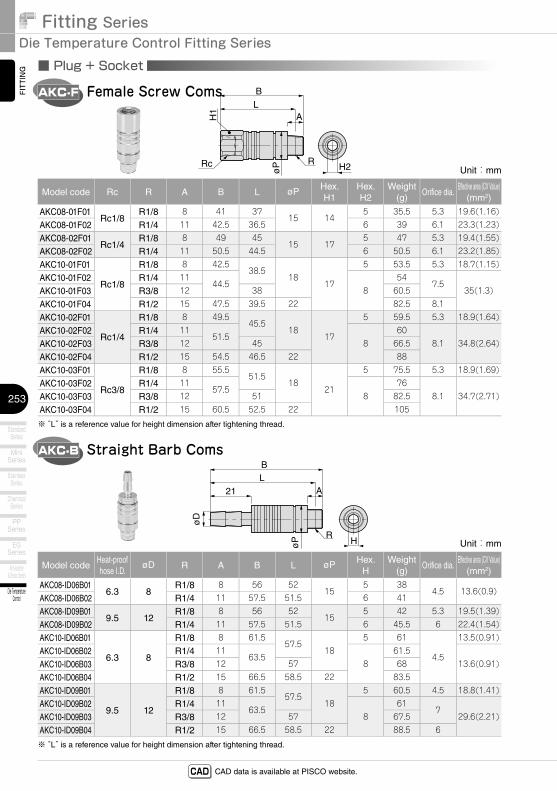
■ Plug + Socket
AKC-F
Unit:mm
Model code Rc R A B L øP Hex.H1
Hex.H2
Weight(g)
Orifice dia.Effective area (CV Value)
(mm2)
AKC08-01F01Rc1/8
R1/8 8 41 3715 14
5 35.5 5.3 19.6(1.16)
AKC08-01F02 R1/4 11 42.5 36.5 6 39 6.1 23.3(1.23)
AKC08-02F01Rc1/4
R1/8 8 49 4515 17
5 47 5.3 19.4(1.55)
AKC08-02F02 R1/4 11 50.5 44.5 6 50.5 6.1 23.2(1.85)
AKC10-01F01
Rc1/8
R1/8 8 42.538.5
1817
5 53.5 5.3 18.7(1.15)
AKC10-01F02 R1/4 1144.5
854
7.535(1.3)AKC10-01F03 R3/8 12 38 60.5
AKC10-01F04 R1/2 15 47.5 39.5 22 82.5 8.1
AKC10-02F01
Rc1/4
R1/8 8 49.545.5
1817
5 59.5 5.3 18.9(1.64)
AKC10-02F02 R1/4 1151.5
860
8.1 34.8(2.64)AKC10-02F03 R3/8 12 45 66.5
AKC10-02F04 R1/2 15 54.5 46.5 22 88
AKC10-03F01
Rc3/8
R1/8 8 55.551.5
1821
5 75.5 5.3 18.9(1.69)
AKC10-03F02 R1/4 1157.5
876
8.1 34.7(2.71)AKC10-03F03 R3/8 12 51 82.5
AKC10-03F04 R1/2 15 60.5 52.5 22 105
※ “L” is a reference value for height dimension after tightening thread.
R
BL
A
H2øPRc
H1
Female Screw Coms
AKC-B
Unit:mm
Model codeHeat-proof hose I.D.
øD R A B L øP Hex.H
Weight(g)
Orifice dia.Effective area (CV Value)
(mm2)
AKC08-ID06B016.3 8
R1/8 8 56 5215
5 384.5 13.6(0.9)
AKC08-ID06B02 R1/4 11 57.5 51.5 6 41
AKC08-ID09B019.5 12
R1/8 8 56 5215
5 42 5.3 19.5(1.39)
AKC08-ID09B02 R1/4 11 57.5 51.5 6 45.5 6 22.4(1.54)
AKC10-ID06B01
6.3 8
R1/8 8 61.557.5
185 61
4.5
13.5(0.91)
AKC10-ID06B02 R1/4 1163.5
861.5
13.6(0.91)AKC10-ID06B03 R3/8 12 57 68
AKC10-ID06B04 R1/2 15 66.5 58.5 22 83.5
AKC10-ID09B01
9.5 12
R1/8 8 61.557.5
185 60.5 4.5 18.8(1.41)
AKC10-ID09B02 R1/4 1163.5
861
729.6(2.21)AKC10-ID09B03 R3/8 12 57 67.5
AKC10-ID09B04 R1/2 15 66.5 58.5 22 88.5 6
※ “L” is a reference value for height dimension after tightening thread.
R
øP
øD
BL
A21
H
Straight Barb Coms

254
http://www.pisco.co.jp
Die TemperatureControl
MinimalSeries
Stop FittingSeries
RotarySeries
Twist-ProofFitting
Block andConnector
Coupling
ColorCap
FITTING
TUB
EVA
LVECONTROLLER
MAKE-TO-ORDERPRODUCTS
CAD data is available at PISCO website.CAD
■ Plug
AKC-P
Unit:mm
Model codeTube O.D.
øD B øP Tube endC
ød Weight(g)
Orifice dia.Recommended socket(thread only)
AKC08-6P 6 34 15 17 4.8 23 4.8 AK08-□SAKC08-8P 8 34.5 15 18.5 6.1 21.5 6.1 AK08-□SAKC10-8P 8 39 18 18.5 8.1 37 7 AK10-□SAKC10-10P 10 41.5 18 21 8.1 37.5 8.1 AK10-□SAKC10-12P 12 50.5 18 23.5 8.1 55.5 8.1 AK10-□S※ . □ in Recommended socket model code / Replaced with Thread size
O-ring
B
C
øD
øP
ød
Straight Tube Plug
AKL-P
Unit:mm
Model codeTube O.D.
øD B øP Tube endC
E ød □SWeight
(g)Orifice
dia.Recommended socket(thread only)
AKL08-6P 6 27 15 17 22 4 12 37 4 AK08-□SAKL08-8P 8 28 15 18.5 24 6 14 42.5 6 AK08-□SAKL10-8P 8 33 18 18.5 24 8.1 14 42.5 6 AK10-□SAKL10-10P 10 34.5 18 21 28 8.1 17 72.5 7.5 AK10-□SAKL10-12P 12 40 18 23.5 31 8.1 20 108 8.1 AK10-□S※ . □ in Recommended socket model code / Replaced with Thread size
B
CE
øD
□S
O-ring
øP
ød
Elbow Tube Plug

Fitting SeriesDie Temperature Control Fitting Series
Die TemperatureControl
255
Anti-spatter& Brass Series
EGSeries
PPSeries
ChemicalSeries
StainlessSeries
MiniSeries
StandardSeries
FITT
ING
CAD data is available at PISCO website.CAD
■ Plug
AKC-FP
Unit:mm
Model code Rc B øP Hex.H
ød Weight(g)
Orifice dia.Recommended socket(thread only)
AKC08-01FP Rc1/8 31 15 14 6.1 26 6.1 AK08-□SAKC08-02FP Rc1/4 39 15 17 6.1 37.5 6.1 AK08-□SAKC10-01FP Rc1/8 32 18 17 7.5 38 7.5 AK10-□SAKC10-02FP Rc1/4 39 18 17 7.5 44.5 8.1 AK10-□SAKC10-03FP Rc3/8 45 18 21 7.5 60 8.1 AK10-□S※ . □ in Recommended socket model code / Replaced with Thread size
B
øP
Rc
H
O-ring
ød
Female Screw Plug
AKC-BP
Unit:mm
Model codeHeat-proof hose I.D.
øD B øP ød Weight(g)
Orifice dia.Recommended socket(thread only)
AKC08-ID06BP 6.3 8 46 15 4.5 28 4.5 AK08-□SAKC08-ID09BP 9.5 12 46 15 6 32.5 6 AK08-□SAKC10-ID06BP 6.3 8 51 18 4.5 46 4.5 AK10-□SAKC10-ID09BP 9.5 12 51 18 7 45 7 AK10-□S※ . □ in Recommended socket model code / Replaced with Thread size
B
øP
O-ring
ød21
øD
Straight Barb Plug

256
http://www.pisco.co.jp
Die TemperatureControl
MinimalSeries
Stop FittingSeries
RotarySeries
Twist-ProofFitting
Block andConnector
Coupling
ColorCap
FITTING
TUB
EVA
LVECONTROLLER
MAKE-TO-ORDERPRODUCTS
CAD data is available at PISCO website.CAD
■ Socket
AK
Unit:mm
Model code R A B L øP1 øP2 Hex.H
Weight(g)
Orifice dia.
AK08-01S R1/8 8 18.5 14.5 13 15 5 10 5.3
AK08-02S R1/4 11 20 14 13 15 6 13 6.3
AK10-01S R1/8 8 21 17 15.5 18 5 15 5.3
AK10-02S R1/4 11 23 17 15.5 18 8 15.5 8.5
AK10-03S R3/8 12 23 16.5 15.5 18 8 22.5 8.5
AK10-04S R1/2 15 26 18 15.5 22 8 44.5 8.5
※ “L” is a reference value for height dimension after tightening thread.
※ . No compatibility with AS (Screw Socket only).
R
BL
A
øP1
H
øP2Screw Socket

Fitting SeriesDie Temperature Control Fitting Series
Die TemperatureControl
257
Anti-spatter& Brass Series
EGSeries
PPSeries
ChemicalSeries
StainlessSeries
MiniSeries
StandardSeries
FITT
ING
CAD data is available at PISCO website.CAD
■ Stop Valve built-in / Plug + Socket
ASC
Unit:mm
Model codeTube O.D.
øD R A B LTube end
CHex.
HWeight
(g)Orifice
dia.Effective area (CV Value)
(mm2)
ASC10-6016
R1/8 857
5317
5 675
12.6(0.66)
ASC10-602 R1/4 11 516
66.512.9(0.67)
ASC10-603 R3/8 12 50.5 73
ASC10-8018
R1/8 860.5
56.518.5
5 71 5.3 19.7(1.17)
ASC10-802 R1/4 11 54.56
70.56.3 21.9(1.27)
ASC10-803 R3/8 12 54 76.5
ASC10-100110
R1/8 862.5
58.521
5 68 5.3 18.6(1.37)
ASC10-1002 R1/4 11 56.56
67.56.3 24.5(1.64)
ASC10-1003 R3/8 12 56 74
ASC10-120112
R1/8 864.5
6023.5
5 74 5.3 18.6(1.48)
ASC10-1202 R1/4 11 58.56
73.56.3 24.7(1.81)
ASC10-1203 R3/8 12 58 80
※ “L” is a reference value for height dimension after tightening thread.
R
øD
ø18
BL
A
C
H
Straight Tube Coms
ASL
Unit:mm
Model codeTube O.D.
øD R A B LTube end
CE
Hex.H
□SWeight
(g)Orifice dia.
Effective area (CV Value)(mm2)
ASL10-6016
R1/8 853
5517 22
512
794
9.4(0.47)
ASL10-602 R1/4 11 536
78.59.4(0.48)
ASL10-603 R3/8 12 52.5 85
ASL10-8018
R1/8 854
5718.5 24
514
86 5.3 18.2(0.97)
ASL10-802 R1/4 11 556
85.56 18.6(1.03)
ASL10-803 R3/8 12 54.5 92
ASL10-100110
R1/8 855.5
6021 28
517
103 5.3 18.7(1.21)
ASL10-1002 R1/4 11 586
102.56.3 24(1.34)
ASL10-1003 R3/8 12 57.5 108
ASL10-120112
R1/8 857
6323.5 31
520
129.5 5.3 18.6(1.34)
ASL10-1202 R1/4 11 616
1296.3 24.4(1.56)
ASL10-1203 R3/8 12 60.5 135.5
※ “L” is a reference value for height dimension after tightening thread.
R
CE
ø18
□S
BL
A
øD
H
Elbow Tube Coms

258
http://www.pisco.co.jp
Die TemperatureControl
MinimalSeries
Stop FittingSeries
RotarySeries
Twist-ProofFitting
Block andConnector
Coupling
ColorCap
FITTING
TUB
EVA
LVECONTROLLER
MAKE-TO-ORDERPRODUCTS
CAD data is available at PISCO website.CAD
ASC-F
Unit:mm
Model code Rc R A B LHex.H1
Hex.H2
Weight(g)
Orifice dia.Effective area (CV Value)
(mm2)
ASC10-01F01Rc1/8
R1/8 853
4919
5 72.5 5.3 18.4(0.98)
ASC10-01F02 R1/4 11 476
726.3 25.9(1.14)
ASC10-01F03 R3/8 12 46.5 78.5
ASC10-02F01Rc1/4
R1/8 860
5619
5 81.5 5.3 18.3(1.43)
ASC10-02F02 R1/4 11 546
816.3 25.9(1.73)
ASC10-02F03 R3/8 12 53.5 87
ASC10-03F01Rc3/8
R1/8 862
5821
5 85 5.3 18.4(1.48)
ASC10-03F02 R1/4 11 566
84.56.3 25.9(1.84)
ASC10-03F03 R3/8 12 55.5 90.5
※ “L” is a reference value for height dimension after tightening thread.
R
ø18Rc
H1
B
LA
H2
Female Screw Coms
ASC-B
Unit:mm
Model codeHeat-proof hose I.D.
øD R A LHex.
HWeight
(g)Orifice
dia.Effective area (CV Value)
(mm2)ASC10-ID06B01
6.3 8R1/8 8 67 5 69
4.513.2(0.83)
ASC10-ID06B02 R1/4 11 656
68.513.6(0.87)
ASC10-ID06B03 R3/8 12 64.5 75
ASC10-ID09B019.5 12
R1/8 8 67 5 75.5 5.3 18.2(1.18)
ASC10-ID09B02 R1/4 11 656
756 21.2(1.34)
ASC10-ID09B03 R3/8 12 64.5 81.5
※ “L” is a reference value for height dimension after tightening thread.
R
ø18
øD
71
LA21
H
Straight Barb Coms

Fitting SeriesDie Temperature Control Fitting Series
Die TemperatureControl
259
Anti-spatter& Brass Series
EGSeries
PPSeries
ChemicalSeries
StainlessSeries
MiniSeries
StandardSeries
FITT
ING
CAD data is available at PISCO website.CAD
■ Stop Valve built-in / Plug
ASC-P
Unit:mm
Model codeTube O.D.
øD BTube end
CWeight
(g)Orifice dia.
Recommended socket(thread only)
ASC10-6P 6 44.5 17 48 5 AS10-□SASC10-8P 8 48 18.5 52 7 AS10-□SASC10-10P 10 50 21 49 8.1 AS10-□SASC10-12P 12 52 23.5 55 8.1 AS10-□S※ . □ in Recommended socket model code / Replaced with Thread size
O-ring
ø18
B
C
øD
ø8
Straight Tube Plug
ASL-P
Unit:mm
Model codeTube O.D.
øD BTube end
CE □S
Weight(g)
Orifice dia.Recommended socket(thread only)
ASL10-6P 6 40.5 17 22 12 60 4 AS10-□SASL10-8P 8 41.5 18.5 24 14 67.5 6 AS10-□SASL10-10P 10 43 21 28 17 84 7.5 AS10-□SASL10-12P 12 44.5 23.5 31 20 111 8.1 AS10-□S※ . □ in Recommended socket model code / Replaced with Thread size
B
CE
øD
ø18
ø8O-ring
□S
Elbow Tube Plug

260
http://www.pisco.co.jp
Die TemperatureControl
MinimalSeries
Stop FittingSeries
RotarySeries
Twist-ProofFitting
Block andConnector
Coupling
ColorCap
FITTING
TUB
EVA
LVECONTROLLER
MAKE-TO-ORDERPRODUCTS
CAD data is available at PISCO website.CAD
ASC-FP
Unit:mm
Model code Rc BHex.
HWeight
(g)Orifice dia.
Recommended socket(thread only)
ASC10-01FP Rc1/8 40.5 19 53.5 8.1 AS10-□SASC10-02FP Rc1/4 47.5 19 62.5 8.1 AS10-□SASC10-03FP Rc3/8 49.5 21 66 8.1 AS10-□S※ . □ in Recommended socket model code / Replaced with Thread size
B
ø18
Rc
H
O-ring
ø8
Female Screw Plug
ASC-BP
Unit:mm
Model codeHeat-proof hose
I.D.øD Weight
(g)Orifice dia.
Recommended socket(thread only)
ASC10-ID06BP 6.3 8 50 4.5 AS10-□SASC10-ID09BP 9.5 12 56.5 6 AS10-□S※ . □ in Recommended socket model code / Replaced with Thread size
58.5
ø18
O-ring
ø821
øD
Straight Barb Plug

Fitting SeriesDie Temperature Control Fitting Series
Die TemperatureControl
261
Anti-spatter& Brass Series
EGSeries
PPSeries
ChemicalSeries
StainlessSeries
MiniSeries
StandardSeries
FITT
ING
CAD data is available at PISCO website.CAD
■ Stop Valve built-in / Socket
AS
Unit:mm
Model code R A LHex.
HWeight
(g)Orifice dia.
AS10-01S R1/8 8 19 5 19 5.3
AS10-02S R1/4 11 17 6 18.5 6.3
AS10-03S R3/8 12 16.5 6 25 6.3
※ “L” is a reference value for height dimension after tightening thread.
※ . No compatibility with AK (Screw Socket only).
R
23
LA
ø15.5
H
ø18Screw Socket
23
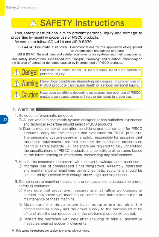
Safety Instructions
SAFETY Instructions
Warning
This safety instructions aim to prevent personal injury and damage to properties by requiring proper use of PISCO products. Be certain to follow ISO 4414 and JIS B 8370
ISO 4414:Pneumatic fluid power…Recomendations for the application of equipment to transmission and control systems.
JIS B 8370:General rules and safety requirements for systems and their components.This safety instructions is classified into “Danger”, “Warning” and “Caution” depending on the degree of danger or damages caused by improper use of PISCO products.
1. Selection of pneumatic products① A user who is a pneumatic system designer or has sufficient experience
and technical expertise should select PISCO products.② Due to wide variety of operating conditions and applications for PISCO
products, carry out the analysis and evaluation on PISCO products. The pneumatic system designer is solely responsible for assuring that the user's requirements are met and that the application presents no health or safety hazards. All designers are required to fully understand the specifications of PISCO products and constitute all systems based on the latest catalog or information, considering any malfunctions.
2. Handle the pneumatic equipment with enough knowledge and experience① Improper use of compressed air is dangerous. Assembly, operation
and maintenance of machines using pneumatic equipment should be conducted by a person with enough knowledge and experience.
3. Do not operate machine / equipment or remove pneumatic equipment until safety is confirmed.① Make sure that preventive measures against falling work-pieces or
sudden movements of machine are completed before inspection or maintenance of these machine.
② Make sure the above preventive measures are completed. A compressed air supply and the power supply to the machine must be off, and also the compressed air in the systems must be exhausted.
③ Restart the machines with care after ensuring to take all preventive measures against sudden movements.
Danger Hazardous conditions. It can cause death or serious personal injury.
Warning Hazardous conditions depending on usages. Improper use of PISCO products can cause death or serious personal injury.
Caution Hazardous conditions depending on usages. Improper use of PISCO products can cause personal injury or damages to properties.
※ . This safety instructions are subject to change without notice.

http://www.pisco.co.jphttp://www.pisco.co.jp
24
Disclaimer1. PISCO does not take any responsibility for any incidental or indirect
loss, such as production line stop, interruption of business, loss of benefits, personal injury, etc., caused by any failure on use or application of PISCO products.
2. PISCO does not take any responsibility for any loss caused by natural disasters, fires not related to PISCO products, acts by third parties, and intentional or accidental damages of PISCO products due to incorrect usage.
3. PISCO does not take any responsibility for any loss caused by improper usage of PISCO products such as exceeding the specification limit or not following the usage the published instructions and catalog allow.
4. PISCO does not take any responsibility for any loss caused by remodeling of PISCO products, or by combinational use with non-PISCO products and other software systems.
5. The damages caused by the defect of Pisco products shall be covered but limited to the full amount of the PISCO products paid by the customer.

25
Safety Instructions
SAFETY INSTRUCTION MANUAL
Danger1. Do not use PISCO products for the following applications.
① Equipment used for maintaining / handling human life and body.② Equipment used for moving / transporting human.③ Equipment specifically used for safety purposes.
Warning1. Do not use PISCO products under the following conditions.
① Beyond the specifications or conditions stated in the catalog, or the instructions.② Under the direct sunlight or outdoors.③ Excessive vibrations and impacts.④ Exposure / adhere to corrosive gas, inflammable gas, chemicals, seawater, water and vapor. *
* Some products can be used under the condition above(④), refer to the details of specification and condition of each product.
2. Do not disassemble or modify PISCO products, which affect the performance, function, and basic structure of the product.
3. Turn off the power supply, stop the air supply to PISCO products, and make sure there is no residual air pressure in the pipes before maintenance and inspection.
4. Do not touch the release-ring of push-in fitting when there is a working pressure. The lock may be released by the physical contact, and tube may fly out or slip out.
5. Frequent switchover of compressed air may generate heat, and there is a risk of causing burn injury.
6. Avoid any load on PISCO products, such as a tensile strength, twisting and bending. Otherwise, there is a risk of causing damage to the products.
7. As for applications where threads or tubes swing / rotate, use Rotary Joints, High Rotary Joints or Multi-Circuit Rotary Block only. The other PISCO products can be damaged in these applications.
8. Use only Die Temperature Control Fitting Series, Tube Fitting Stainless SUS316 Series, Tube Fitting Stainless SUS316 Compression Fitting Series or Tube Fitting Brass Series under the condition of over 60℃ (140°F) water or thermal oil. Other PISCO products can be damaged by heat and hydrolysis under the condition above.
9. As for the condition required to dissipate static electricity or provide an antistatic performance, use EG series fitting and antistatic products only, and do not use other PISCO products. There is a risk that static electricity can cause system defects or failures.
10. Use only Fittings with a characteristic of spatter-proof such as Anti-spatter or Brass series in a place where flame and weld spatter is produced. There is a risk of causing fire by sparks.
11. Turn off the power supply to PISCO products, and make sure there is no residual air pressure in the pipes and equipment before maintenance. Follow the instructions below in order to ensure safety.① Make sure the safety of all systems related to PISCO products before maintenance.② Restart of operation after maintenance shall be proceeded with care after
ensuring safety of the system by preventive measures against unexpected movements of machines and devices where pneumatic equipment is used.
③ Keep enough space for maintenance when designing a circuit.12. Take safety measures such as providing a protection cover if there is a
risk of causing damages or fires on machine / facilities by a fluid leakage.
PISCO products are designed and manufactured for use in general industrial machines. Be sure to read and follow the instructions below.

http://www.pisco.co.jphttp://www.pisco.co.jp
26
Caution1. Remove dusts or drain before piping. They may get into the peripheral
machine / facilities and cause malfunction.2. When inserting an ultra-soft tube into push-in fitting, make sure to place
an Insert Ring into the tube edge. There is a risk of causing the escape of tube and a fluid leakage without using an Insert Ring.
3. The product incorporating NBR as seal rubber material has a risk of malfunction caused by ozone crack. Ozone exists in high concentrations in static elimination air, clean-room, and near the high-voltage motors, etc. As a countermeasure, material change from NBR to HNBR or FKM is necessary. Consult with PISCO for more information.
4. Special option “Oil-free” products may cause a very small amount of a fluid leakage. When a fluid medium is liquid or the products are required to be used in harsh environments, contact us for further information.
5. In case of using non-PISCO brand tubes, make sure the tolerance of the outer tube diameter is within the limits of Table 1.
●Table 1. Tube O.D. Tolerancemm size Nylon tube Polyurethane tube inch size Nylon tube Polyurethane tubeø1.8mm ─ ±0.05mm ø1/8 ±0.1mm ±0.15mmø3mm ─ ±0.15mm ø5/32 ±0.1mm ±0.15mmø4mm ±0.1mm ±0.15mm ø3/16 ±0.1mm ±0.15mmø6mm ±0.1mm ±0.15mm ø1/4 ±0.1mm ±0.15mmø8mm ±0.1mm ±0.15mm ø5/16 ±0.1mm ±0.15mmø10mm ±0.1mm ±0.15mm ø3/8 ±0.1mm ±0.15mmø12mm ±0.1mm ±0.15mm ø1/2 ±0.1mm ±0.15mmø16mm ±0.1mm ±0.15mm ø5/8 ±0.1mm ±0.15mm
6. Instructions for Tube Insertion① Make sure that the cut end surface of the tube is at right angle without
a scratch on the surface and deformations.② When inserting a tube, the tube needs to be inserted fully into the push-
in fitting until the tubing edge touches the tube end of the fitting as shown in the figure below. Otherwise, there is a risk of leakage.
Tube end
Sealing
Tube is not fully inserted up to tube end.
③ After inserting the tube, make sure it is inserted properly and not to be disconnected by pulling it moderately.
※. When inserting tubes, Lock-claws may be hardly visible in the hole, observed from the front face of the release-ring. But it does not mean the tube will surely escape. Major causes of the tube escape are the followings; ①Shear drop of the lock-claws edge②The problem of tube diameter (usually small)Therefore, follow the above instructions from ① to ③, even lock-claws is hardly visible.

27
7. Instructions for Tube Disconnection① Make sure there is no air pressure inside of the tube, before disconnecting it.② Push the release-ring of the push-in fitting evenly and deeply enough to
pull out the tube toward oneself. By insufficient pushing of the release-ring, the tube may not be pulled out or damaged by scratch, and tube shavings may remain inside of the fitting, which may cause the leakage later.
8. Instructions for Installing a fitting① When installing a fitting, use proper tools to tighten a hexagonal-column
or an inner hexagonal socket. When inserting a hex key into the inner hexagonal socket of the fitting, be careful so that the tool does not touch lock-claws. The deformation of lock-claws may result in a poor performance of systems or an escape of the tube.
② Refer to Table 2 which shows the recommended tightening torque. Do not exceed these limits to tighten a thread. Excessive tightening may break the thread part or deform the gasket and cause a fluid leakage. Tightening thread with tightening torque lower than these limits may cause a loosened thread or a fluid leakage.
③ Adjust the tube direction while tightening thread within these limits, since some PISCO products are not rotatable after the installation.
●Table 2: Recommended tightening torque / Sealock color / Gasket materialsThread type Thread size Tightening torque Sealock color Gasket materials
Metric thread
M3×0.5 0.7N·m
─
SUS304NBR
M5×0.8 1.0 ~ 1.5N·mM6×1 2 ~ 2.7N·m
M3×0.5 0.5 ~ 0.6N·m
POMM5×0.8 1 ~ 1.5N·mM6×0.75 0.8 ~ 1N·mM8×0.75 1 ~ 2N·m
Taper pipe thread
R1/8 7 ~ 9N·m
White ─R1/4 12 ~ 14N·mR3/8 22 ~ 24N·mR1/2 28 ~ 30N·m
Unified thread No.10-32UNF 1.0 ~ 1.5N·m ─ SUS304、NBR
National pipe thread taper
1/16-27NPT 7 ~ 9N·m
White ─1/8-27NPT 7 ~ 9N·m1/4-18NPT 12 ~ 14N·m3/8-18NPT 22 ~ 24N·m1/2-14NPT 28 ~ 30N·m
※ These values may differ for some products. Refer to each specification as well.9. Instructions for removing a fitting
① When removing a fitting, use proper tools to loosen a hexagonal-column or an inner hex bolt.
② Remove the sealant stuck on the mating equipment. The remained sealant may get into the peripheral equipment and cause malfunctions.
10. Arrange piping avoiding any load on fittings and tubes such as twist, tensile, moment load, shaking and physical impact. These may cause damages to fittings, tube deformations, bursting and the escape of tubes.
Safety Instructions
Fitting SeriesFITTING
33
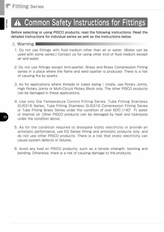
Common Safety Instructions for Fittings
Warning
Before selecting or using PISCO products, read the following instructions. Read the detailed instructions for individual series as well as the instructions below.
1.��Do�not�use� fittings�with� fluid�medium�other� than�air� or�water.� (Water� can�be�used�with�some�series.)�Contact�us�for�using�other�kind�of�fluid�medium�except�air�and�water.
2.��Do�not�use�fittings�except�Anti-spatter,�Brass�and�Brass�Compression�Fitting�series�in�a�place�where�the�flame�and�weld�spatter�is�produced.�There�is�a�risk�of�causing�fire�by�sparks.
3.��As�for�applications�where�threads�or�tubes�swing�/�rotate,�use�Rotary�Joints,�High�Rotary�Joints�or�Multi-Circuit�Rotary�Block�only.�The�other�PISCO�products�can�be�damaged�in�these�applications.
4.��Use� only�Die�Temperature�Control� Fitting�Series,� Tube� Fitting�Stainless�SUS316�Series,� Tube� Fitting�Stainless�SUS316�Compression� Fitting�Series�or�Tube�Fitting�Brass�Series�under� the�condition�of�over�60℃ (140° F)�water�or� thermal� oil.�Other�PISCO�products�can�be�damaged�by�heat�and�hydrolysis�under�the�condition�above.
5.��As� for� the� condition� required� to� dissipate� static� electricity� or� provide� an�antistatic�performance,�use�EG�Series�fitting�and�antistatic�products�only,�and�do� not� use� other�PISCO�products.� There� is� a� risk� that� static� electricity� can�cause�system�defects�or�failures.
6.��Avoid� any� load� on�PISCO�products,� such� as� a� tensile� strength,� twisting� and�bending.�Otherwise,�there�is�a�risk�of�causing�damage�to�the�products.

FITTING
TUBE
VALVE
CONTROLLER
StandardSeries
MiniSeries
StainlessSeries
ChemicalSeries
PPSeries
EGSeries
Anti-spatter& Brass Series
Die TemperatureControl
MinimalSeries
Stop FittingSeries
RotarySeries
Twist-ProofFitting
Block andConnector
Coupling
ColorCap
http://www.pisco.co.jphttp://www.pisco.co.jp
34
MAKE-TO-ORDERPRODUCTS
Caution1.In�case�of�using�non-PISCO�brand�tubes,�make�sure�the�tolerance�of�the�outer�tube�diameter�is�within�the�following�limits�of�Table�1.
●Table�1.�Tube�O.D.�Tolerancemm size Nylon tube Urethane tube inch size Nylon tube Urethane tubeø1.8mm ─ ±0.05mm ø1/8 ±0.1mm ±0.15mmø3mm ─ ±0.15mm ø5/32 ±0.1mm ±0.15mmø4mm ±0.1mm ±0.15mm ø3/16 ±0.1mm ±0.15mmø6mm ±0.1mm ±0.15mm ø1/4 ±0.1mm ±0.15mmø8mm ±0.1mm ±0.15mm ø5/16 ±0.1mm ±0.15mmø10mm ±0.1mm ±0.15mm ø3/8 ±0.1mm ±0.15mmø12mm ±0.1mm ±0.15mm ø1/2 ±0.1mm ±0.15mmø16mm ±0.1mm ±0.15mm ø5/8 ±0.1mm ±0.15mm
2.�Instructions�for�Tube�Insertion①�Make�sure�that�the�cut�end�surface�of�the�tube� is�at� right�angle�without�a�scratch�on�the�tube�surface�and�deformations.
②�When� inserting�a�tube,� the�tube�needs�to�be� inserted� fully� into�the�push-in�fitting�until�the�tubing�edge�touches�the�tube�end�of�the�fitting�as�shown�in�the�figure�below.�Otherwise,�there�is�a�risk�of�leakage.
Tube end
Sealing
Tube is not fully inserted up to tube end.
③�After� inserting� the� tube,�make� sure� it� is� inserted� properly� and� not� to� be�disconnected�by�pulling�it�moderately.
3.�Instructions�for�Tube�Disconnection①�Make�sure�there�is�no�air�pressure�inside�of�the�tube,�before�disconnecting�it.
②�Push�the�release-ring�of�the�push-in�fitting�evenly�and�deeply�enough�to�pull�out�the�tube�toward�oneself.�By� insufficient�pushing�of�the�release-ring,�the�tube�may�not�be�pulled�out�or�damaged�by�scratch,�and�tube�shavings�may�remain�inside�of�the�fitting,�which�may�cause�the�leakage�later.

Fitting SeriesFITTING
35
5.Instructions�for�removng�a�fitting①�When�removing�a� fitting,�use�proper�tools�to� loosen�a�hexagonal-column�or�an�inner�hexagonal�socket.
②�Remove�the�sealant�stuck�on�the�mating�equipment.�The�remained�sealant�may�get�into�the�peripheral�equipment�and�cause�malfunctions.
6.Arrange�piping�avoiding�any�load�on�fittings�and�tubes�such�as�twist,�tensile,�moment�load,�shaking�and�physical�impact.�These�may�cause�damages�to�fittings,�tube�deformations,�bursting�and�the�escape�of�tubes.
4.�Instructions�for�Installing�a�fitting①�When�installing�a�fitting,�use�proper�tools�to�tighten�a�hexagonal-column�or�an�inner�hexagonal�socket.�When�inserting�a�hex�key�into�the�inner�hexagonal�socket�of�the�fitting,�be�careful�so�that�the�tool�does�not�touch� lock-claws.�The�deformation�of� lock-claws�may�result� in�a�poor�performance�of�systems�or�an�escape�of�the�tube.
②�Refer�to�Table�2�which�shows�the� recommended�tightening�torque.�Do�not�exceed� these� limits� to� tighten� a� thread.� Excessive� tightening�may� break�the�thread�part�or�deform�the�gasket�and�cause�a�fluid� leakage.�Tightening�thread�with�tightening�torque�lower�than�these�limits�may�cause�a�loosened�thread�or�a�fluid�leakage.
③�Adjust� the� tube�direction�while� tightening� thread�within� these� limits,� since�some�PISCO�products�are�not�rotatable�the�installation.
●Table�2:�Recommended�tightening�torque�/�Sealock�color�/�Gasket�materialsThread type Thread size Tightening torque Sealock color Gasket materials
Metric thread
M3×0.5 0.7N·m
─
SUS304NBR
M5×0.8 1.0 ~ 1.5N·mM6×1 2 ~ 2.7N·m
M3×0.5 0.5 ~0.6N·m
POMM5×0.8 1 ~1.5N·mM6×0.75 0.8 ~ 1N·mM8×0.75 1 ~ 2N·m
Taper pipe thread
R1/8 7 ~ 9N·m
White ─R1/4 12 ~ 14N·mR3/8 22 ~ 24N·mR1/2 28 ~ 30N·m
Unified thread No.10-32UNF 1.0 ~ 1.5N·m ─ SUS304、NBR
National pipe thread taper
1/16-28NPT 7 ~ 9N·m
White ─1/8-27NPT 7 ~ 9N·m1/4-18NPT 12 ~ 14N·m3/8-18NPT 22 ~ 24N·m1/2-14NPT 28 ~ 30N·m
※.These�values�may�differ�for�some�products.�Refer�to�each�specification�as�well