diffusive and martensitic nucleation kinetics in solid ... · diffusive and martensitic nucleation...
TRANSCRIPT

ARTICLE
Received 12 Sep 2016 | Accepted 19 Feb 2017 | Published 15 May 2017
Diffusive and martensitic nucleation kineticsin solid-solid transitions of colloidal crystalsYi Peng1, Wei Li1, Feng Wang1, Tim Still2, Arjun G. Yodh2 & Yilong Han1,3
Solid–solid transitions between crystals follow diffusive nucleation, or various diffusionless
transitions, but these kinetics are difficult to predict and observe. Here we observed the rich
kinetics of transitions from square lattices to triangular lattices in tunable colloidal thin films
with single-particle dynamics by video microscopy. Applying a small pressure gradient in
defect-free regions or near dislocations markedly transform the diffusive nucleation with an
intermediate-stage liquid into a martensitic generation and oscillation of dislocation pairs
followed by a diffusive nucleus growth. This transformation is neither purely diffusive nor
purely martensitic as conventionally assumed but a combination thereof, and thus presents
new challenges to both theory and the empirical criterion of martensitic transformations. We
studied how pressure, density, grain boundary, triple junction and interface coherency affect
the nucleus growth, shape and kinetic pathways. These novel microscopic kinetics cast new
light on control solid–solid transitions and microstructural evolutions in polycrystals.
DOI: 10.1038/ncomms14978 OPEN
1 Department of Physics, Hong Kong University of Science and Technology, Clear Water Bay, Hong Kong SAR, China. 2 Department of Physics and Astronomy,University of Pennsylvania, Philadelphia, Pennsylvania 19104, USA. 3 The HKUST Shenzhen Research Institute, Shenzhen 518057, China. Correspondence andrequests for materials should be addressed to Y.H. (email: [email protected]).
NATURE COMMUNICATIONS | 8:14978 | DOI: 10.1038/ncomms14978 | www.nature.com/naturecommunications 1

Solid–solid (s–s) transitions are arguably the most commontype of structural phase transitions, and prevail in naturaland man-made systems1. s–s transitions are a central
interest in metallurgy and crystallography, but the lack ofobservations at the single-particle level in the bulk has resultedin many controversies. Their kinetic pathways follow either adiffusive nucleation or a diffusionless martensitic transformationwith particles moving in concert1,2. Martensitic transformationsoccur widely in alloys1, ceramics, minerals, inorganiccompounds3 and proteins4. If the symmetries of the parent andthe product lattices have a group–subgroup relation, then theparent lattice deforms continuously into the product latticewithout any bond breaking2. Such displacive or weak2 martensitictransformations often found in shape-memory alloys5–7 and giantmagnetocaloric materials8,9; when a group–subgroup relationin symmetries does not exist, the martensitic nucleationinvolves interparticle bond-breaking. Such reconstructivemartensitic nucleation occurs in metals, alloys and someinsulating materials2. Displacive martensitic transformationsoften propagate at the speed of sound, while reconstructivemartensitic transformations propagate much slower.
Reconstructive s–s transitions are theoretically difficult becausean order parameter cannot be defined easily without a group–subgroup relation in the lattice symmetries2,10. s–s transitions arealso challenging to simulate due to the sluggish dynamics11. Toaccelerate the dynamics, simulations were usually performed insmall systems12, under pressure gradients or even shock waves13
to overcome the high free-energy barriers. Experimentally, s–stransitions have been studied by calorimetry14, X-ray scattering15,acoustic emission16 and transmission electron microscopy17,18,but these techniques cannot resolve the initial stage of nucleationdue to the small spatial and timescales. Consequently, themicroscopic kinetics of their transition pathways and associatedmechanisms remain poorly understood. A central unansweredquestion about s–s transitions concerns whether theirkinetic pathways follow a martensitic or a diffusive nucleationprocess11,15,17,19.
Colloids are outstanding model systems for phase transitionstudies because micron-sized colloidal particles can be imageddirectly by optical microscopy and their thermal motions can betracked by image processing20. Compared with crystallization21,melting22,23 and glass transitions24, s–s transitions in colloidalsystems have been much understudied25–31. To drive a s–stransition, the colloidal crystal needs to be tunable. For example,an electric-field-induced transition between face-centred cubic(f.c.c.) and body-centred tetragonal (b.c.t.) colloidal crystals wasreported to be diffusive for f.c.c.-b.c.t., but martensitic for thereverse b.c.t.-f.c.c. transition31. S–s transitions in tunablecolloidal crystals have been achieved in small crystallites ofDNA-coated colloidal spheres26,32 and in electric- or magnetic-field-driven s–s transitions27,28,30,31. These systems underwentrapid displacive martensitic transformations. The early-stagedynamic processes of the displacive martensitic transformationshave not been studied.
Here we study the reconstructive s–s transition between squareand triangular lattices, which is one of the simplest s–s transitionswithout a group–subgroup relation33. It occurs within largecrystalline domains, and the dynamics process can be wellcaptured. In particular, we examine how a pressure gradientaffects the s–s transition, enhances the free-energy barriercrossing and promotes the collective motion of particles, thusresulting in new kinetic behaviours. Phase transitions underpressure gradients represent a simple type of non-equilibriumphase transitions, which are poorly understood yet hugelyimportant for both basic science and technologicalapplications34. In fact, most s–s transitions in earth mantel and
steel production occur under anisotropic pressure. Here we findrich results about microscopic kinetics in s–s transitions underisotropic or small anisotropic pressures. The major discovery isan early-stage martensitic transformation and a late-stagediffusive nucleation. This result reveals the role of diffusion inthe martensitic transformation, which has been discussed in latestage of some martenstic transformations at high temperatures,for example, during the tempering of martensite and in variousintermediate structures like Bainite and Widmanstaetten ferrite1.We suggest that this pathway could widely exist in atomic systemsbecause once a nucleus formed martensitically, its surface shouldact like a grain boundary, whereas grain boundaries are known tosuppress martensitic transition and promote diffusive nucleation.This hybrid kinetics indicates the breakdown of an empiricalcriterion of martensitic transformation, that is, the special anglebetween the parent and product lattices are not necessarilyindicating a pure martensitic transformation. Some conceptsand terminologies in metallurgy are explained in SupplementaryNote 1 since they are seldom used in soft matter physics.
ResultsSample preparation and experimental set-up. The tunablecolloidal crystals were composed of poly(N-isopropylacrylamide)(NIPA) microgel spheres whose diameter, s, linearly changesfrom 0.76 mm at 26.4 �C to 0.67 mm at 30.6 �C (SupplementaryFig. 2a)22. These short-range repulsive spheres (SupplementaryFig. 2b)29 exhibit nearly the same phase behaviour as hardspheres22,23. When spheres are confined between two parallelplates, they can self-assemble into a cascade of crystalline phasesas the plate separation H increases: 1D; 2&; 2D; 3&; 3D; ?(refs 35,36). Here 1D denotes monolayer triangular lattice,2& denotes two-layer square lattice and so on. Similarstructures have been observed in plasmas37 and electronbilayers in semiconductors38. The phase behaviour isdetermined by the volume fraction f and H/s (refs 35,36). Bytuning s with the temperature, both H/s and f will change,resulting in an n&-(n� 1)D transition along a tilted path in thephase diagram (Supplementary Fig. 3)36.
We heated the interior of a grain with the square lattice using abeam of light with a typical heated area of 105 particles per layer(Supplementary Fig. 4)23. We studied the homogeneous s–stransition in a locally defect-free region, or the heterogeneous s–stransition near a dislocation, in a grain boundary or in a triplejunction of grain boundaries by choosing a heated area with thedesired defects. By contrast, s–s transitions in atomic systems areusually under certain defect densities of various defects, thussingle-defect effects and homogenous nucleation are difficult tostudy. The heated area in the focal plane equilibrated to atemperature Tambþ dT, where the ambient temperature Tamb wastuned with 0.1 �C resolution using the temperature controller anddT¼ 1.6 �C is the local optical heating effect, which can bereached in 3 s after switching on the light (SupplementaryFig. 2c)23. This sudden change in temperature produced asuperheated metastable &-lattice. We monitored its evolutiontowards the equilibrium D-lattice under a constant T (that is,at constant f and H/s). The s–s transition can occur whenTamboTs� soTambþ dToTm (that is, famb4 fs� s4famb
þ df4fm), where Tm and Ts� s correspond to the meltingand s–s transitions, respectively. The heating effect is uniformenough in the central p(38 mm)2 area of the focal plane(Supplementary Fig. 4) and in the z direction for such thinsamples23.
In most experiments, the colloid was partially filled in thesample cell with air trapped in the corners. Gently pressing onecorner induced a tiny drift (flow rate no0.1 mm s� 1) of the
ARTICLE NATURE COMMUNICATIONS | DOI: 10.1038/ncomms14978
2 NATURE COMMUNICATIONS | 8:14978 | DOI: 10.1038/ncomms14978 | www.nature.com/naturecommunications

crystal, which lasted for approximately an hour and slowly variedover several minutes (Supplementary Fig. 5). The crystal driftedas a whole without interlayer gliding under such a low n. Westudied the s–s transitions under different n in 50 experimentaltrials and consistently obtained three types of kinetics in threeparameter regimes. In some of the experiments, we applied abetter controlled flow using a microfluidic device shown inSupplementary Fig. 10 and obtained similar kinetic pathways.Similar behaviours were observed in n&-(n� 1)D transitionsfor different n. When nuclei are larger than H, their shapes wereroughly uniform in the z direction, and so we mainly monitoredthe surface layer. We record particle motions using a charge-coupled device camera at 10 frames per s. Particle positions weretracked from the image analysis39. Experimental details areprovided in the Methods.
Nucleation inside crystalline domains. Previously we reportedthe s–s transition in such colloidal thin films under isotropicstress29. The transition exhibited a two-step nucleation pathway:n&-liquid nucleus-(n� 1)D, which was confirmed insimulation40. This pathway is favoured because a small nucleusis dominated by the interfacial energy instead of the bulkchemical potential, and forming s–s interfaces costs more energythan solid–liquid interfaces. Recently, the intermediate liquidnucleus has been observed in a three-dimensional (3D) atomiccrystal41, which confirmed that the mechanism is general for bothcolloidal and atomic systems.
Here we observed that the intermediate liquid nucleus vanishedunder a small flow of merely n\10 nm s� 1 (Fig. 1). After a longincubation period in a defect-free region, a row of several particlesshifted from the bulk layer to the surface layer forming a pair ofdislocations with opposite Burgers vectors. The newly insertedrow was always oriented along the[10] or [01] direction of the&-lattice and tended to be aligned with the direction of the flow.The two dislocations glided and oscillated in opposite directionsperpendicular to the inserted row of particles, which produced afew more dislocation pairs. These dislocation pairs formed inparallel and arranged in a line (Fig. 1). Interparticle bonds brokewhen new rows of particles were inserted (that is, plasticdeformation) but not when the dislocation pairs oscillated (thatis, elastic deformation). Each inserted row of particles distortedthe local &-lattice to a D-lattice, forming a tiny twinningstructure labelled by two mirror-symmetrical parallelograms inFig. 1d. The twinning structure did not grow large because it willinduce strain energy in the parent phase. These disconnectedD-lattice ‘butterflies’ vanished and born as the dislocation pairsoscillated, thus we called the dislocation pairs as nucleationprecursor rather than nucleus. Generally, before the nucleusforms, the parent phase would often develop a certain structurethat would reduce the free-energy barrier and trigger thenucleation. Such a nucleation precursor has attracted substantialinterest in the studies of crystallization42,43, melting23 and s–stransitions44. For example, elastic lattice softening has been detec-ted in Ti–Ni-based alloys before martensitic transformations44,but the structure and dynamics of this precursor have not beenobserved at the microscopic scale. In the two-step nucleationunder a negligible flow (no10 nm s� 1), we previously found thatthe precursors were in fact particle-swapping loops rather thanthe conventionally assumed crystal defects29. Here we found thatthe precursors at n410 nm s� 1 were oscillating dislocation pairs,which represent a new type of nucleation precursor. Suchmartensitic type of precursor has not been suggested before.Here we call it martensitic precursor, which is beyond theconventional structural description (for example, vacancies45
or dislocations46 in melting; dense42 or ordered43 blobs incrystallization) of nucleation precursors.
From Fig. 1i–l, dislocation pairs collectively and rapidlydistorted the &-lattice into a D-lattice (Fig. 1k,l) as an in-planedisplacive martensitic nucleation without any bond breaking. Theresulting nucleus was elliptical in the xy plane with a uniformshape along the z direction, and the habit planes were labelled bythe yellow lines in Fig. 1l. Similar dislocation-pair distributionson the elliptical nucleus surface have been observed in atomicsystems1,47, but their kinetics and formation processes are notavailable. Here we observed that multiple dislocation pairs in theprecursor stage acted like a post-critical nucleus: they irreversiblyinduced more dislocation pairs to form leading to an ellipticalpost-critical nucleus. In contrast, the critical size of a liquidnucleus is about 50–100 particles per layer in the two-stepdiffusive nucleation under no flow29. Besides the collectiveformation and oscillation of dislocation pairs, this nucleationprecursor process exhibited another four features of martensitictransition1: (1) particles were aligned in parallel lines across thenucleus surface as shown in Fig. 1l; (2) the displacement of eachparticle was within one lattice constant; (3) the elliptical nucleusshape has a much higher aspect ratio than those of diffusivenucleation1,29; and (4) the lattice orientations of all the nucleifollowed a particular angle relative to the parent lattice (that is,45� or [10]& || [11]D in Figs 1–4). In addition, the major axis ofthe elliptical nucleus was always at 45� relative to the ambient&-lattice (Figs 1k and 2d).
The later stage of post-critical nucleus growth is crucial to thephase transition speed and final microstructures. The martensiticnucleation in Fig. 1a–l yielded a post-critical nucleus, whichrapidly grew via the attachment of individual diffusive particleswithout collective motions (Fig. 1m–o). The crossover from theearly-stage martensitic nucleation to the later diffusive growth isnot sharp at high f; rows of particles were collectively insertedonto the nucleus’ tips and other particles individually attached tothe nucleus’ surface (Fig. 2e,f and Supplementary Movie 3). Whenthe nucleus grew large, the growth became purely diffusive(Fig. 2g) because the energy barrier is higher to collectiveinserting a long row of particles into a larger nucleus.
As the elliptical nuclei grew diffusively, their aspect ratiosdecreased and they developed facets (Figs 1m–o and 2e–g). Allthe nuclei surfaces propagated at speeds below 100 nm s� 1 (forexample, Figs 1p and 2h), which is much lower than the speed ofsound B0.1 m s� 1 in typical colloidal crystals48. This is a featureof diffusive nucleation and distinct from the martensitic growth,which usually grow at a much higher speed close to that ofsound1. We observed that the facet propagated more slowly at ahigher f, for more coherent facets, or downstream of theflow (see the slopes in Figs 1p and 2h). Typically a nucleusfirst developed six facets that were usually at 45� and15�(¼ 60�� 45�) relative to the &-lattice, hence they wereincoherent, that is, the two lattices did not completely match atthe interface (Supplementary Fig. 1). By contrast, coherentinterfaces with 0� mismatch typically formed in nuclei at grainboundaries and triple junctions. The mismatch of incoherentinterfaces provides space for particle rearrangement, henceincoherent interfaces propagate much faster than coherentinterfaces (Supplementary Movie 5)1,29. This can also beexplained in terms of energy: coherent interfaces have thelowest energy, and thus it is more difficult to from high-energykinks to trigger interface propagation. In addition, we found thatincoherent facets propagated at similar speeds under an isotropicstress without flow29, but exhibited different speeds under a flow.In Figs 1m–o and 2e–g the upstream particles have higherLindemann parameter L (that is, lower f), and thus have morespace to rearrange themselves and transform into a D-lattice.Consequently, facet VI propagated faster than facet III inFig. 1n,p, and facet IV propagated faster than facet II in
NATURE COMMUNICATIONS | DOI: 10.1038/ncomms14978 ARTICLE
NATURE COMMUNICATIONS | 8:14978 | DOI: 10.1038/ncomms14978 | www.nature.com/naturecommunications 3

Fig. 2f,h. Facets I and IV in Fig. 1n were along the flow direction,thus they extended quickly along the lateral direction andpropagated slowly along the normal direction. Note that a fastlateral growth corresponds to a slow normal growth of this facetand fast normal growth of neighbouring facets and vice versa1,29.This is similar to the observed higher mobilities of grain
boundaries perpendicular to an external pressure49. L nearfacet I was higher than that near facet IV, thus facet I grew faster(Fig. 1n–p). Facets II and V in Fig. 1n were almost perpendicularto the flow, thus they grew rapidly along their normal directionsand slowly along their lateral directions. Consequently, they wereeventually overwhelmed by neighbouring facets and the nucleus
I II
III
IV
I
III
IVm n o440 s 460 s 510 sp
V
VI VI
0.02 0.2
Crystal Liquid
8IIIIIVVI
6
4
2
0440 460 480 500 520
t (s)
d (μ
m)
f
a b c
e g
i
394 s 396 s 398 s
400 s 407 s 409 s
415 s 422 s
45°
h 409 s
j 415 s
d 398 s
422 slk
L
Figure 1 | Flow-induced early-stage martensitic precursors and later-stage diffusive nucleus growth. The 5&-4D transition occurred at a locally
defect-free region. The generated dislocations are labelled with ?. The flows were along the x direction of the images (labelled by the arrow below m) and
moved at n¼ 11 nm s� 1. Optical heating commenced at t¼0 s. (a–o) correspond to Supplementary Movies 1 and 2, respectively. (a) A defect-free region in
the 5&-lattice. (b) A small gap marked by the ellipse in red developed under thermal fluctuation at t¼ 396 s. (c) A row of three particles labelled in white
moved from the bulk layer to the gap in the surface layer, forming a pair of dislocations. (d) The same image as c can be viewed as a very small
D-lattice precursor labelled by the yellow ‘butterfly’. The dislocations glided in opposite directions and oscillated at B0.2 Hz with an amplitude of two
lattice constants, then generated new gaps and new dislocation pairs alternatively around the first pair. All the dislocation pairs were arranged in a line and
oscillated in phase during the nucleation precursor stage e–i. From i–l, the dislocation pairs stopped oscillating and martensitically formed an elliptical
D-lattice nucleus. In l, the 2 yellow lines indicated the habit planes and the 13 red lines are along the lattice orientations in the parent and product phases.
The martensitic nucleus then grew in all directions through diffusion in m–o. The colour bar above p shows different values of the dynamical Lindemann
parameter L used in m–o. Liquid-like particles are defined as particles with L40.2 and low bond-orientational orders and are labelled in red23 (Methods).
They swapped positions with neighbouring particles, hence they are liquid, not glass. Scale bars, 5 mm. The nucleus developed facets in n and grew into a
parallelogram shape in o. The D-lattice had one layer less than the &-lattice in the z direction, hence it was more compact in the xy plane with lower
Lindemann parameters and about 3% lower lattice constant as the nucleus grew larger. (m–o) Coloured by Lindemann parameter L. Red colour represents
liquid-like particles, which L40.2 and low bond-orientational order parameter (Methods)29. (p) Displacements of the four facets along their normal
directions after subtracting the background flow.
ARTICLE NATURE COMMUNICATIONS | DOI: 10.1038/ncomms14978
4 NATURE COMMUNICATIONS | 8:14978 | DOI: 10.1038/ncomms14978 | www.nature.com/naturecommunications

took the shape of a parallelogram. In addition, the early history,for example, whether the nucleation was from a pre-existingdefect (Fig. 2a) or via a two-step nucleation with an intermediateliquid state (Supplementary Fig. 7), did not affect the facetpropagation speed.
A large crystalline domain usually contained multiple nuclei(Fig. 3). For two-step diffusive nucleation with an intermediateliquid nucleus at no10 nm s� 1, the lattice orientations of nucleiare mainly random, a feature of diffusive nucleation17. Fornucleation at n410 nm s� 1, the nucleus lattices exhibit a 45�angle relative to the parent lattice (that is, [10]D || [11]&) due tothe early-stage martensitic precursor (Fig. 3).
The definitions of martensitic and diffusive transformations arebased on the dynamic motions of particles, which are difficult to
observe in bulk atomic crystals. Therefore, martensitictransformations are often identified indirectly from staticstructures such as the angle between the parent and productlattices. For example, by quenching the crystal during thetransformation and cutting up the bulk, the lattice orientationsof the frozen nuclei at the exposed cross-section can be observedby electron microscopy17. If the orientations between the parentand product lattices exhibit a special relation (for example,[10]D||[11]& in Figs 1–4), then it is identified as a martensitictransformation; if the mismatch angles are random, then it is adiffusive nucleation1,17. We found that this empirical criterionbased on crystallographic relationship for martensitic transitionmay not always hold because a rapid martensitic precursor caninduce a special mismatch angle, even though the nucleationprocess is mainly diffusive (Figs 1–3). Note that the latticemismatch angle cannot be changed easily after the embryo hasformed because a high energy barrier must be overcome to rotatethe whole nucleus. Moreover, we conjecture that a reconstructivemartensitic nucleation could later change into diffusive growth inatomic crystals for three reasons. First, once a nucleus forms, thetransformation at its incoherent surface should be diffusive sincea collective lattice distortion is difficult in geometry. Second, inmetallurgy martensitic transformations generally do not occur atgrain boundaries1,17. Surfaces of nuclei have similar structures tograin boundaries and thus should have similar effects. Third, insome atomic martensitic transformations, the aspect ratios ofnewly formed nuclei are usually very high but are reduced as thenuclei grow1. This could be attributed to the diffusive growth,which is rather isotropic compared with the anisotropicmartensitic deformation. Before nuclei form, there is no s–sinterface inside crystalline domains, hence the nucleation tends tooccur martensitically since it is not easy for particles to diffuseindividually in a defect-free region. After the nucleus forms,
a b c d840 s 843 s 850 s 875 s
e f g900 s 1064 s 1100 s h
III
I
II
IV aIV b
III
I
II
IV
9000
2
4
III
III
IV a
IV b
6
1,000 1,100
t (s)
d (μ
m)
Figure 2 | The nucleation process near a pre-existing dislocation. (a–g) correspond to Supplementary Movies 3 and 4, respectively. A row of four bulk
particles were inserted into the surface layer and formed a dislocation pair on the low-density side of the dislocation after 843 s of incubation. The
dislocation pair oscillated and induced more pairs, resulting in an elliptical D-lattice nucleus, which grew into a parallelogram shape through both diffusion
and the collective insertion of rows of particles (coloured in white). After 1,100 s, the nucleus growth was purely diffusive. The D-lattice was oriented along
the major axis of the ellipse and at 45� relative to the &-lattice in d. Colours in e–g represent the Lindemann parameters as in Fig. 1m–o. (h) Displacements
of the four facets along their normal directions after subtracting the background flow. When the nucleus became large, the diffusive growth (solid symbols)
dominates over the collective insertion of rows of particles (open symbols). From f–g, facet IVb became shorter and eventually vanished as facet I
propagated to the left corresponding to its negative slope near 1,100 s in h. Scale bars, 5 mm.
a b
Figure 3 | Multiple nuclei formed within one crystalline domain. The
early-stage martensitic nucleation dictated the lattice orientation of all the
D-lattices to be 45� relative to the &-lattice. The lattice orientations of the
D-lattices are parallel (that is, 45��45�¼0�) in a and perpendicular
(45�þ45�¼ 90�) in b. The small angles between the D-lattices in a are
due to the defects and the nucleus-expansion-induced lattice distortion in
the ambient &-lattice. The flows were along the x direction of the images
(labelled by the arrow below a). Scale bars, 5 mm.
NATURE COMMUNICATIONS | DOI: 10.1038/ncomms14978 ARTICLE
NATURE COMMUNICATIONS | 8:14978 | DOI: 10.1038/ncomms14978 | www.nature.com/naturecommunications 5
its incoherent interfaces promote the diffusive nucleation. Thismechanism of early-stage martensitic and later-stage diffusivenucleation is expected to be independent of colloidal and atomicsystems.
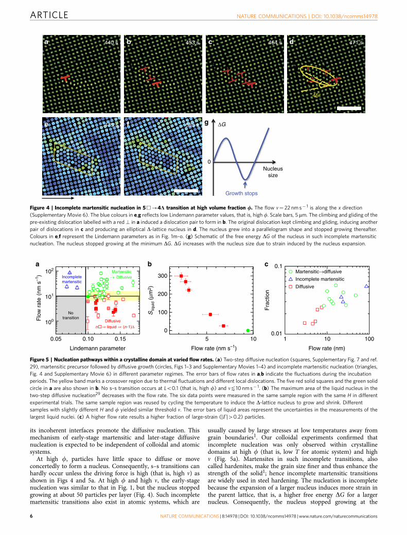
At high f, particles have little space to diffuse or moveconcertedly to form a nucleus. Consequently, s–s transitions canhardly occur unless the driving force is high (that is, high n) asshown in Figs 4 and 5a. At high f and high n, the early-stagenucleation was similar to that in Fig. 1, but the nucleus stoppedgrowing at about 50 particles per layer (Fig. 4). Such incompletemartensitic transitions also exist in atomic systems, which are
usually caused by large stresses at low temperatures away fromgrain boundaries1. Our colloidal experiments confirmed thatincomplete nucleation was only observed within crystallinedomains at high f (that is, low T for atomic system) and highn (Fig. 5a). Martensites in such incomplete transitions, alsocalled hardenites, make the grain size finer and thus enhance thestrength of the solid1; hence incomplete martensitic transitionsare widely used in steel hardening. The nucleation is incompletebecause the expansion of a larger nucleus induces more strain inthe parent lattice, that is, a higher free energy DG for a largernucleus. Consequently, the nucleus stopped growing at the
a b c d440 s 453 s 464 s 471 s
45°
g ΔG
Nucleussize
0
Growth stops
475 se 585 sf
Figure 4 | Incomplete martensitic nucleation in 5&-4D transition at high volume fraction /. The flow n¼ 22 nm s� 1 is along the x direction
(Supplementary Movie 6). The blue colours in e,g reflects low Lindemann parameter values, that is, high f. Scale bars, 5 mm. The climbing and gliding of the
pre-existing dislocation labelled with a red ? in a induced a dislocation pair to form in b. The original dislocation kept climbing and gliding, inducing another
pair of dislocations in c and producing an elliptical D-lattice nucleus in d. The nucleus grew into a parallelogram shape and stopped growing thereafter.
Colours in e,f represent the Lindemann parameters as in Fig. 1m–o. (g) Schematic of the free energy DG of the nucleus in such incomplete martensitic
nucleation. The nucleus stopped growing at the minimum DG. DG increases with the nucleus size due to strain induced by the nucleus expansion.
a b
n liquid (n-1)Δ
cF
ract
ion
Sliq
uid
(μm
2 )
Flo
w r
ate
(nm
s–1
)
0.1Martensitic→diffusive
Incomplete martensitic
Diffusive
0.011 1050.05
100
101
102
0.10
Incompletemartensitic
MartensiticDiffusive
Notransition
0.15
0
100
200
300
10 100
Flow rate (nm)Flow rate (nm s–1)Lindemann parameter
Diffusive
Figure 5 | Nucleation pathways within a crystalline domain at varied flow rates. (a) Two-step diffusive nucleation (squares, Supplementary Fig. 7 and ref.
29), martensitic precursor followed by diffusive growth (circles, Figs 1–3 and Supplementary Movies 1–4) and incomplete martensitic nucleation (triangles,
Fig. 4 and Supplementary Movie 6) in different parameter regimes. The error bars of flow rates in a,b indicate the fluctuations during the incubation
periods. The yellow band marks a crossover region due to thermal fluctuations and different local dislocations. The five red solid squares and the green solid
circle in a are also shown in b. No s–s transition occurs at Lo0.1 (that is, high f) and nt10 nm s� 1. (b) The maximum area of the liquid nucleus in the
two-step diffusive nucleation29 decreases with the flow rate. The six data points were measured in the same sample region with the same H in different
experimental trials. The same sample region was reused by cycling the temperature to induce the D-lattice nucleus to grow and shrink. Different
samples with slightly different H and f yielded similar threshold n. The error bars of liquid areas represent the uncertainties in the measurements of the
largest liquid nuclei. (c) A higher flow rate results a higher fraction of large-strain (|G|40.2) particles.
ARTICLE NATURE COMMUNICATIONS | DOI: 10.1038/ncomms14978
6 NATURE COMMUNICATIONS | 8:14978 | DOI: 10.1038/ncomms14978 | www.nature.com/naturecommunications
minimum DG as illustrated in Fig. 4g. Similar DG curves haverecently been found in the 3D crystallization of DNA-coatedcolloidal spheres50 and in the two-dimensional (2D)crystallization on a curved surface51.
Figure 5b shows that the maximum area of the intermediateliquid nucleus in the two-step nucleation can be hundreds ofparticles per layer. These particles are clearly liquid-like since theyactively swapped positions with neighbouring particles. Theliquid nucleus size decreased with n and vanished atn\10 nm s� 1 (Fig. 5b). Although such a small n could hardlyinduce any discernable layering in liquid52, it effectivelypromoted the formation of a D-lattice and suppressed theliquefaction of the &-lattice, which presents new challenges totheory. Although our observed 10 nm s� 1 flow and the estimatedpressure gradient 0.3 Pa m� 2 are very small, they could havesignificant effect for colloidal crystals because they are muchsofter than atomic crystals. If the elastic modulus of an atomiccrystal is 1010 times larger than our colloidal crystal, we expectthat a 109 Pa m� 2 pressure gradient can help to align liquidparticles with a better order and suppress the intermediate-stageliquid in atomic crystal.
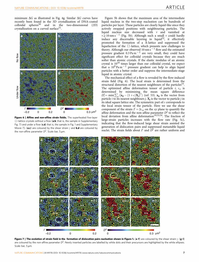
The mechanical effect of a flow is revealed by the flow-inducedstrain field (Fig. 6). The local strain is determined from thestructural distortion of the nearest neighbours of the particles53.The optimized affine deformation tensor of particle i, Ei, isdetermined by minimizing the mean square differenceD2
i¼ minðP
j xij�ð1þ EÞXj� �2Þ (ref. 53). xij is the vector from
particle i to its nearest neighbours j. Xj is the vector to particle j inits ideal square lattice site. The symmetric part of E corresponds tothe local strain tensor of the particle. Here we use the shearcomponent of the strain G¼ 2Exy on the xy plane to quantify theaffine deformation and the non-affine parameter D2 to reflect thelocal deviation from affine deformation19,53,54. The fraction oflarge-strain particles increases with the flow rate (Fig. 5c),indicating that the flow-induced large shear strain assisted thegeneration of dislocation pairs and suppressed metastable liquidnuclei. The strain fields about G and D2 are rather uniform and
a b
c d
0 0.2 0 0.3 μm2�–0.2
D2
No
flow
U
nder
flow
Figure 6 | Affine and non-affine strain fields. The superheated five-layer
&-lattice crystals without a flow (a,b; that is, the sample in Supplementary
Fig. 7) and under a flow (c,d; that is, the sample in Fig. 1 and Supplementary
Movie 7). (a,c) are coloured by the shear strain g and b,d are coloured by
the non-affine parameter D2. Scale bar, 5 mm.
394 s 398 s
406 s 407 s
414 s 415 s
394 s 398 s
406 s 407 s
414 s 415 sf
a b
c
e
g
i
h
jd
lk
0 0.3 μm20 0.2–0.2D2
�
Figure 7 | The evolution of strain field in the formation of dislocation pairs nucleation shown in Figure 1. (a–f) are coloured by the shear strain g. (g–l)
are coloured by the non-affine parameter D2. Newly inserted particles are labelled by white dots and their precursors are highlighted by the white ellipses.
Scale bar, 5 mm.
NATURE COMMUNICATIONS | DOI: 10.1038/ncomms14978 ARTICLE
NATURE COMMUNICATIONS | 8:14978 | DOI: 10.1038/ncomms14978 | www.nature.com/naturecommunications 7

small in space-time under no flow, and fluctuated strongly withlarge-strain clusters under a flow (Fig. 6). Large shear strainclusters highlighted by ellipses in Fig. 7a,c,e triggered theformation of dislocation pairs, and induced plastic deformationsassociated with large non-affine strain (red particles in Fig. 7g–l.If the dislocation pairs did not form, that is, without a row ofinserted particles, then the region of large affine strain relaxed to&-lattice rapidly (Supplementary Movie 7).
The dynamics of non-affineness can determine the nucleationkinetics55. If the propagation speed of non-affineness is fast, that is,of the same order as the nucleation kinetics, then the bond-breaking in the non-affineness transformation induces a diffusivenucleation. On the other hand, the transformation is martensitic ifthe nucleation front driven by the affine strain is faster than thepropagation of non-affineness. In the initial stage of our s–stransitions under flows, the affine strain occurred before the non-affine part and propagated anisotropically (Fig. 7), thus thetransformation was martensitic; whereas at the later stage, the non-affine strain propagated at the same speed of the nucleus growth(Supplementary Fig. 9), thus the transformation was diffusive.
Nucleation near dislocations. Pre-existing defects strongly affectphase transition kinetics. Dislocations are expected to promotemartensitic transformations due to their elastic strain energy1.The densities of martensitic nuclei and pre-existing dislocationswere found to be proportional in metals and alloys1, but the effectof a single dislocation is unclear. Here we observed thatnucleation had a higher chance near a single pre-existingdislocation than in a defect-free region because of a lowerfree-energy barrier. The nucleation kinetics was similar to that inthe defect-free region, that is, two to five pairs of dislocations wereformed via concerted motions followed by diffusive growth (Fig. 2and Supplementary Movies 3 and 4). An edge dislocation can beviewed as a perfect crystal missing a half plane of particles. Thus,the density is lower on one side of the dislocation. We observedthat the inserted rows of several particles were always on thelower density side and parallel to the missing half plane ofparticles (Fig. 2) in different samples regardless of the flowdirection. The motion of a pre-existing dislocation triggered theinsertion of a row of particles at a few lattice constants away.
Nucleation at grain boundaries. Most crystals contain numerousgrain boundaries and triple junctions, hence their effects on thes–s transition are particularly important. We found that thenucleation at grain boundaries and triple junctions can exhibitdifferent kinetics. When nt10 nm s� 1, the s–s transition at agrain boundary or an asymmetric triple junction is similar to thatinside a domain, that is, it follows a two-step diffusive nucleationwith an intermediate liquid nucleus29. When n\10 nm s� 1,however, the transition at grain boundaries becomes a one-stepdiffusive nucleation without the intermediate liquid nucleus(Fig. 8). The early-stage martensitic nucleation was absent fromgrain boundaries and triple junctions, which is consistent with thebehaviours in atomic systems1,17. Grain boundaries acted as asink for small defects, hence their nearby lattices were highlyordered without distortions and strains. Consequently, they didnot promote martensitic transformations. On the other hand,L within four layers of a grain boundary were higher22, thuspromoting the diffusive nucleation. The nucleation occurred atthe grain boundary rather than at the nearby dislocations or inthe defect-free regions in Fig. 8, demonstrating that thenucleation barrier at the grain boundary was lower. Figure 8shows a lower L (that is, higher f) but a shorter incubation timethan does Fig. 2, indicating that the nucleation occurred moreeasily at the grain boundary than inside the domain.
As the nucleus grew larger, it developed two coherent facets fora lower interfacial energy. The other two incoherent facetsoriented 45� away from the square lattice. Such a 45� inclinationangle (Supplementary Fig. 1) can be seen in Figs 1–4 and 8,indicating that such facets have a relatively lower interfacialenergy. Grain boundaries with different mismatch angles andinclination angles (Supplementary Fig. 1) caused nuclei to takedifferent polygonal shapes, with most having incoherent facetsand one or two coherent facets. Incoherent facets (for example,facets III and IV in Fig. 8c) are rough. Thus, particles from theparent phase can easily transform into the product phase andinduce nucleus growth. In contrast, the coherent facets tended tomaintain a low-energy flat shape. Thus, they had few sites toattach particles and propagated slowly. The coherent facets (forexample, facets I and II in Fig. 8c) started propagating mainlyfrom the junctions of grain boundaries where particles diffusedonto the coherent facet and formed ledges and kinks (Fig. 8c).&-lattice particles tended to transform into D-lattice particles atthe kinks, resulting in the growth of ledges and propagation ofcoherent facets. Such microscopic growth kinetics has not beenproposed or observed before, but could exist in atomic systemsbecause the mechanism is simple and should not be limited tocolloids.
Nucleation at a symmetric triple junction. We found thatapplying a small flow is not the only way to suppress theintermediate liquid nucleus during the &�D transformation.Figure 9 shows a D-lattice directly nucleating at a triple junctionthrough the diffusion of individual particles without forming
1050 s d 1100 sc
LedgeKink
a 420 s b 615 s
I
II
III
IV
Figure 8 | 5&-4D diffusive nucleation at a grain boundary. The flow
was along the x direction of the images (labelled by the arrow below c) with
hni¼ 36 nm s� 1 (Supplementary Movie 8). Colours represent Lindemann
parameters as in Fig. 1m–o. Optical heating commenced at t¼0 s. Scale bar,
5 mm. (a) The incubation stage. (b) At t¼415 s, red particles on the grain
boundary swapped positions with their neighbours and formed a D-lattice
nucleus. (c) The nucleus grew through particle diffusion and developed
facets. (d) At 1,100 s, the nucleus grew into a polygon with coherent facets I
and II and incoherent facets III and IV at 45� relative to the &-lattice.
The kinks on the coherent facets originated from particle diffusions at the
grain boundary.
ARTICLE NATURE COMMUNICATIONS | DOI: 10.1038/ncomms14978
8 NATURE COMMUNICATIONS | 8:14978 | DOI: 10.1038/ncomms14978 | www.nature.com/naturecommunications
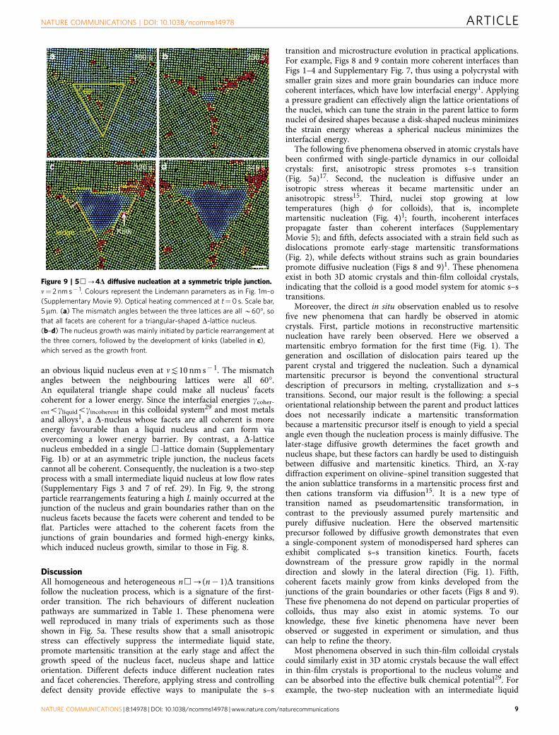
an obvious liquid nucleus even at nt10 nm s� 1. The mismatchangles between the neighbouring lattices were all 60�.An equilateral triangle shape could make all nucleus’ facetscoherent for a lower energy. Since the interfacial energies gcoher-
entogliquidogincoherent in this colloidal system29 and most metalsand alloys1, a D-nucleus whose facets are all coherent is moreenergy favourable than a liquid nucleus and can form viaovercoming a lower energy barrier. By contrast, a D-latticenucleus embedded in a single &-lattice domain (SupplementaryFig. 1b) or at an asymmetric triple junction, the nucleus facetscannot all be coherent. Consequently, the nucleation is a two-stepprocess with a small intermediate liquid nucleus at low flow rates(Supplementary Figs 3 and 7 of ref. 29). In Fig. 9, the strongparticle rearrangements featuring a high L mainly occurred at thejunction of the nucleus and grain boundaries rather than on thenucleus facets because the facets were coherent and tended to beflat. Particles were attached to the coherent facets from thejunctions of grain boundaries and formed high-energy kinks,which induced nucleus growth, similar to those in Fig. 8.
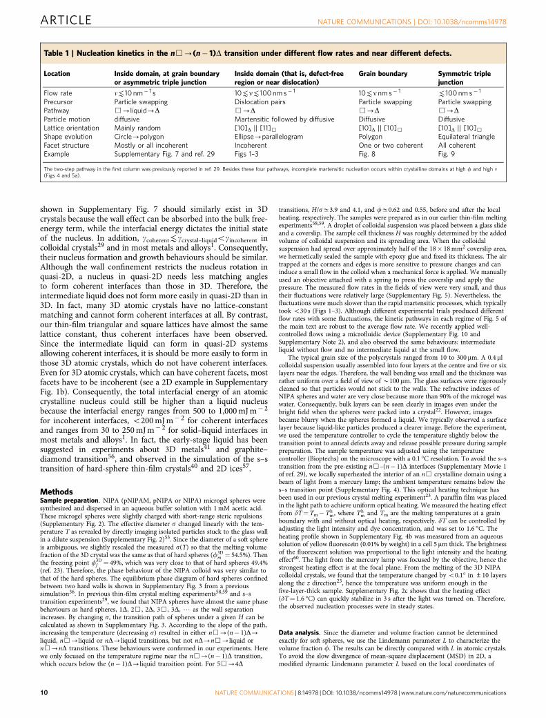
DiscussionAll homogeneous and heterogeneous n&-(n� 1)D transitionsfollow the nucleation process, which is a signature of the first-order transition. The rich behaviours of different nucleationpathways are summarized in Table 1. These phenomena werewell reproduced in many trials of experiments such as thoseshown in Fig. 5a. These results show that a small anisotropicstress can effectively suppress the intermediate liquid state,promote martensitic transition at the early stage and affect thegrowth speed of the nucleus facet, nucleus shape and latticeorientation. Different defects induce different nucleation ratesand facet coherencies. Therefore, applying stress and controllingdefect density provide effective ways to manipulate the s–s
transition and microstructure evolution in practical applications.For example, Figs 8 and 9 contain more coherent interfaces thanFigs 1–4 and Supplementary Fig. 7, thus using a polycrystal withsmaller grain sizes and more grain boundaries can induce morecoherent interfaces, which have low interfacial energy1. Applyinga pressure gradient can effectively align the lattice orientations ofthe nuclei, which can tune the strain in the parent lattice to formnuclei of desired shapes because a disk-shaped nucleus minimizesthe strain energy whereas a spherical nucleus minimizes theinterfacial energy.
The following five phenomena observed in atomic crystals havebeen confirmed with single-particle dynamics in our colloidalcrystals: first, anisotropic stress promotes s–s transition(Fig. 5a)17. Second, the nucleation is diffusive under anisotropic stress whereas it became martensitic under ananisotropic stress15. Third, nuclei stop growing at lowtemperatures (high f for colloids), that is, incompletemartensitic nucleation (Fig. 4)1; fourth, incoherent interfacespropagate faster than coherent interfaces (SupplementaryMovie 5); and fifth, defects associated with a strain field such asdislocations promote early-stage martensitic transformations(Fig. 2), while defects without strains such as grain boundariespromote diffusive nucleation (Figs 8 and 9)1. These phenomenaexist in both 3D atomic crystals and thin-film colloidal crystals,indicating that the colloid is a good model system for atomic s–stransitions.
Moreover, the direct in situ observation enabled us to resolvefive new phenomena that can hardly be observed in atomiccrystals. First, particle motions in reconstructive martensiticnucleation have rarely been observed. Here we observed amartensitic embryo formation for the first time (Fig. 1). Thegeneration and oscillation of dislocation pairs teared up theparent crystal and triggered the nucleation. Such a dynamicalmartensitic precursor is beyond the conventional structuraldescription of precursors in melting, crystallization and s–stransitions. Second, our major result is the following: a specialorientational relationship between the parent and product latticesdoes not necessarily indicate a martensitic transformationbecause a martensitic precursor itself is enough to yield a specialangle even though the nucleation process is mainly diffusive. Thelater-stage diffusive growth determines the facet growth andnucleus shape, but these factors can hardly be used to distinguishbetween diffusive and martensitic kinetics. Third, an X-raydiffraction experiment on olivine–spinel transition suggested thatthe anion sublattice transforms in a martensitic process first andthen cations transform via diffusion15. It is a new type oftransition named as pseudomartensitic transformation, incontrast to the previously assumed purely martensitic andpurely diffusive nucleation. Here the observed martensiticprecursor followed by diffusive growth demonstrates that evena single-component system of monodispersed hard spheres canexhibit complicated s–s transition kinetics. Fourth, facetsdownstream of the pressure grow rapidly in the normaldirection and slowly in the lateral direction (Fig. 1). Fifth,coherent facets mainly grow from kinks developed from thejunctions of the grain boundaries or other facets (Figs 8 and 9).These five phenomena do not depend on particular properties ofcolloids, thus may also exist in atomic systems. To ourknowledge, these five kinetic phenomena have never beenobserved or suggested in experiment or simulation, and thuscan help to refine the theory.
Most phenomena observed in such thin-film colloidal crystalscould similarly exist in 3D atomic crystals because the wall effectin thin-film crystals is proportional to the nucleus volume andcan be absorbed into the effective bulk chemical potential29. Forexample, the two-step nucleation with an intermediate liquid
a 100 s b 230 s
c 320 s
60°
ledge
d 345 s
Kink
Figure 9 | 5&-4D diffusive nucleation at a symmetric triple junction.
n¼ 2 nm s� 1. Colours represent the Lindemann parameters as in Fig. 1m–o
(Supplementary Movie 9). Optical heating commenced at t¼0 s. Scale bar,
5 mm. (a) The mismatch angles between the three lattices are all B60�, so
that all facets are coherent for a triangular-shaped D-lattice nucleus.
(b–d) The nucleus growth was mainly initiated by particle rearrangement at
the three corners, followed by the development of kinks (labelled in c),
which served as the growth front.
NATURE COMMUNICATIONS | DOI: 10.1038/ncomms14978 ARTICLE
NATURE COMMUNICATIONS | 8:14978 | DOI: 10.1038/ncomms14978 | www.nature.com/naturecommunications 9
shown in Supplementary Fig. 7 should similarly exist in 3Dcrystals because the wall effect can be absorbed into the bulk free-energy term, while the interfacial energy dictates the initial stateof the nucleus. In addition, gcoherenttgcrystal–liquidogincoherent incolloidal crystals29 and in most metals and alloys1. Consequently,their nucleus formation and growth behaviours should be similar.Although the wall confinement restricts the nucleus rotation inquasi-2D, a nucleus in quasi-2D needs less matching anglesto form coherent interfaces than those in 3D. Therefore, theintermediate liquid does not form more easily in quasi-2D than in3D. In fact, many 3D atomic crystals have no lattice-constantmatching and cannot form coherent interfaces at all. By contrast,our thin-film triangular and square lattices have almost the samelattice constant, thus coherent interfaces have been observed.Since the intermediate liquid can form in quasi-2D systemsallowing coherent interfaces, it is should be more easily to form inthose 3D atomic crystals, which do not have coherent interfaces.Even for 3D atomic crystals, which can have coherent facets, mostfacets have to be incoherent (see a 2D example in SupplementaryFig. 1b). Consequently, the total interfacial energy of an atomiccrystalline nucleus could still be higher than a liquid nucleusbecause the interfacial energy ranges from 500 to 1,000 mJ m� 2
for incoherent interfaces, o200 mJ m� 2 for coherent interfacesand ranges from 30 to 250 mJ m� 2 for solid–liquid interfaces inmost metals and alloys1. In fact, the early-stage liquid has beensuggested in experiments about 3D metals41 and graphite–diamond transition56, and observed in the simulation of the s–stransition of hard-sphere thin-film crystals40 and 2D ices57.
MethodsSample preparation. NIPA (pNIPAM, pNIPA or NIPA) microgel spheres weresynthesized and dispersed in an aqueous buffer solution with 1 mM acetic acid.These microgel spheres were slightly charged with short-range steric repulsions(Supplementary Fig. 2). The effective diameter s changed linearly with the tem-perature T as revealed by directly imaging isolated particles stuck to the glass wallin a dilute suspension (Supplementary Fig. 2)53. Since the diameter of a soft sphereis ambiguous, we slightly rescaled the measured s(T) so that the melting volumefraction of the 3D crystal was the same as that of hard spheres (f3D
m ¼ 54.5%). Thenthe freezing point f3D
f ¼ 49%, which was very close to that of hard spheres 49.4%(ref. 23). Therefore, the phase behaviour of the NIPA colloid was very similar tothat of the hard spheres. The equilibrium phase diagram of hard spheres confinedbetween two hard walls is shown in Supplementary Fig. 3 from a previoussimulation36. In previous thin-film crystal melting experiments58,59 and s–stransition experiments29, we found that NIPA spheres have almost the same phasebehaviours as hard spheres, 1D, 2&, 2D, 3&, 3D, ? as the wall separationincreases. By changing s, the transition path of spheres under a given H can becalculated as shown in Supplementary Fig. 3. According to the slope of the path,increasing the temperature (decreasing s) resulted in either n&-(n� 1)D-liquid, n&-liquid or nD-liquid transitions, but not nD-n&-liquid orn&-nD transitions. These behaviours were confirmed in our experiments. Herewe only focused on the temperature regime near the n&-(n� 1)D transition,which occurs below the (n� 1)D-liquid transition point. For 5&-4D
transitions, H/sC3.9 and 4.1, and fC0.62 and 0.55, before and after the localheating, respectively. The samples were prepared as in our earlier thin-film meltingexperiments58,59. A droplet of colloidal suspension was placed between a glass slideand a coverslip. The sample cell thickness H was roughly determined by the addedvolume of colloidal suspension and its spreading area. When the colloidalsuspension had spread over approximately half of the 18� 18 mm2 coverslip area,we hermetically sealed the sample with epoxy glue and fixed its thickness. The airtrapped at the corners and edges is more sensitive to pressure changes and caninduce a small flow in the colloid when a mechanical force is applied. We manuallyused an objective attached with a spring to press the coverslip and apply thepressure. The measured flow rates in the fields of view were very small, and thustheir fluctuations were relatively large (Supplementary Fig. 5). Nevertheless, thefluctuations were much slower than the rapid martensitic processes, which typicallytook o30 s (Figs 1–3). Although different experimental trials produced differentflow rates with some fluctuations, the kinetic pathways in each regime of Fig. 5 ofthe main text are robust to the average flow rate. We recently applied well-controlled flows using a microfluidic device (Supplementary Fig. 10 andSupplementary Note 2), and also observed the same behaviours: intermediateliquid without flow and no intermediate liquid at the small flow.
The typical grain size of the polycrystals ranged from 10 to 300 mm. A 0.4 mlcolloidal suspension usually assembled into four layers at the centre and five or sixlayers near the edges. Therefore, the wall bending was small and the thickness wasrather uniform over a field of view of B100 mm. The glass surfaces were rigorouslycleaned so that particles would not stick to the walls. The refractive indexes ofNIPA spheres and water are very close because more than 90% of the microgel waswater. Consequently, bulk layers can be seen clearly in images even under thebright field when the spheres were packed into a crystal22. However, imagesbecame blurry when the spheres formed a liquid. We typically observed a surfacelayer because liquid-like particles produced a clearer image. Before the experiment,we used the temperature controller to cycle the temperature slightly below thetransition point to anneal defects away and release possible pressure during samplepreparation. The sample temperature was adjusted using the temperaturecontroller (Bioptechs) on the microscope with a 0.1 �C resolution. To avoid the s–stransition from the pre-existing n&–(n� 1)D interfaces (Supplementary Movie 1of ref. 29), we locally superheated the interior of an n& crystalline domain using abeam of light from a mercury lamp; the ambient temperature remains below thes–s transition point (Supplementary Fig. 4). This optical heating technique hasbeen used in our previous crystal melting experiment23. A paraffin film was placedin the light path to achieve uniform optical heating. We measured the heating effectfrom dT¼Tm�Th
m, where Thm and Tm are the melting temperatures at a grain
boundary with and without optical heating, respectively. dT can be controlled byadjusting the light intensity and dye concentration, and was set to 1.6 �C. Theheating profile shown in Supplementary Fig. 4b was measured from an aqueoussolution of yellow fluorescein (0.01% by weight) in a cell 5 mm thick. The brightnessof the fluorescent solution was proportional to the light intensity and the heatingeffect60. The light from the mercury lamp was focused by the objective, hence thestrongest heating effect is at the focal plane. From the melting of the 3D NIPAcolloidal crystals, we found that the temperature changed by o0.1� in ±10 layersalong the z direction23, hence the temperature was uniform enough in thefive-layer-thick sample. Supplementary Fig. 2c shows that the heating effect(dT¼ 1.6 �C) can quickly stabilize in 3 s after the light was turned on. Therefore,the observed nucleation processes were in steady states.
Data analysis. Since the diameter and volume fraction cannot be determinedexactly for soft spheres, we use the Lindemann parameter L to characterize thevolume fraction f. The results can be directly compared with L in atomic crystals.To avoid the slow divergence of mean-square displacement (MSD) in 2D, amodified dynamic Lindemann parameter L based on the local coordinates of
Table 1 | Nucleation kinetics in the n&-(n� 1)D transition under different flow rates and near different defects.
Location Inside domain, at grain boundaryor asymmetric triple junction
Inside domain (that is, defect-freeregion or near dislocation)
Grain boundary Symmetric triplejunction
Flow rate nt10 nm� 1 s 10tnt100 nm s� 1 10tn nm s� 1 t100 nm s� 1
Precursor Particle swapping Dislocation pairs Particle swapping Particle swappingPathway &-liquid-D &-D &-D &-DParticle motion diffusive Martensitic followed by diffusive Diffusive DiffusiveLattice orientation Mainly random [10]D || [11]& [10]D || [10]& [10]D || [10]&Shape evolution Circle-polygon Ellipse-parallelogram Polygon Equilateral triangleFacet structure Mostly or all incoherent Incoherent One or two coherent All coherentExample Supplementary Fig. 7 and ref. 29 Figs 1–3 Fig. 8 Fig. 9
The two-step pathway in the first column was previously reported in ref. 29. Besides these four pathways, incomplete martensitic nucleation occurs within crystalline domains at high f and high n(Figs 4 and 5a).
ARTICLE NATURE COMMUNICATIONS | DOI: 10.1038/ncomms14978
10 NATURE COMMUNICATIONS | 8:14978 | DOI: 10.1038/ncomms14978 | www.nature.com/naturecommunications

neighbouring particles is often used61:
L2ðtÞ¼ DrrelðtÞð Þ2� �
2a2¼
DuiðtÞ�DujðtÞ� �2D E
2a2; ð1Þ
where a is the lattice constant measured from the position of the first peak of theradial distribution function g(r), Drrel is the relative neighbour–neighbourdisplacement, Dui is the displacement of particle i, particles i and j are nearestneighbours, and hi is the ensemble average. The factor 1/2 arises from the fact thatthe Lindemann parameter describes the displacement relative to the equilibriumposition, while the dynamic MSD h(Drrel(t))2i describes the displacement relativeto a previous time. L is measured from � 2 to þ 2 s around each frame and iscolour-coded in Figs 1,2,4,8 and 9, Supplementary Fig. 7 and in SupplementaryMovies 1,3,5,6,8 and 9 according to the colour bar shown above Fig. 1p of the maintext. The dynamic MSD reaches a plateau due to the caging of neighbouringparticles in o1 s (Supplementary Fig. 6), and thus 4 s trajectories are long enoughfor calculating L. A dislocation can enhance the L value of its four layers ofneighbours22, which is approximately the distance between the newly formednucleus and the pre-existing dislocation (Fig. 2b of the main text). 2D localorientational orders cmi �
Pnnij¼1 emiyj=nni (ref. 59). i¼
ffiffiffiffiffiffiffiffi� 1p
. m¼ 4 and 6correspond to four- and six-fold symmetries, respectively. yj is the orientationalangle of the bond between particle i and its nearest neighbour j. nni is the numberof nearest neighbours for particle i. The nearest neighbours are identified from theDelaunay triangulations, which yield hnni¼ 6 for any distribution of particles in2D. Hence it is ideal for triangular lattices, but not for square lattices whosehnni¼ 4. Therefore, the nearest neighbours for square lattices are further confinedto those particles within a distance of o1.2a, which is the midpoint between thelattice constant a and the distance to the second nearest neighbour
ffiffiffi2p
a (ref. 59).A crystalline bond is defined as jc�micmjj � 0:5 (ref. 62). A &- or D-crystallineparticle is defined as a particle with more than two four-fold crystalline bonds ormore than three six-fold crystalline bonds, respectively. Other particles are definedas liquid. Liquid particles can be accurately identified since they must satisfy boththe bond-orientational order criterion and the Lindemann parameter criterion, andare not very sensitive to threshold changes. Moreover, we confirmed the identifiedliquid-like particles from the videos: liquid-like particles swapped positions, butsolid-like particles did not.
Data availability. The data that support the findings of this study are available onrequest from the first author Y.P. or the corresponding author Y.H.
References1. Porter, D. A., Easterling, K. E. & Sherif, M. Y. Phase Transformations in Metals
and Alloys (CRC Press, 2008).2. Bhattacharya, K., Conti, S., Zanzotto, G. & Zimmer, J. Crystal symmetry and
the reversibility of martensitic transformations. Nature 428, 55–59 (2004).3. Delaey, L. Diffusionless Transformations (Wiley Online Library, 2013).4. Olson, G. & Hartman, H. Martensite and life: displacive transformations as
biological processes. J. Phys. Colloques 43, C4–855 (1982).5. Kainuma, R. et al. Magnetic-field-induced shape recovery by reverse phase
transformation. Nature 439, 957–960 (2006).6. Tanaka, Y. et al. Ferrous polycrystalline shape-memory alloy showing huge
superelasticity. Science 327, 1488–1490 (2010).7. Song, Y., Chen, X., Dabade, V., Shield, T. W. & James, R. D. Enhanced
reversibility and unusual microstructure of a phase-transforming material.Nature 502, 85–88 (2013).
8. Moya, X. et al. Giant and reversible extrinsic magnetocaloric effects in La0.7Ca0. 3MnO3 films due to strain. Nat. Mater. 12, 52–58 (2013).
9. Liu, J., Gottschall, T., Skokov, K. P., Moore, J. D. & Guteisch, O. Giantmagnetocaloric effect driven by structural transitions. Nat. Mater. 11, 620–626(2012).
10. Toledano, P. & Dmitriev, V. Reconstructive Phase Transitions (World Scientific,1996).
11. Khaliullin, R. Z., Eshet, H., Kuhne, T. D., Behler, J. & Parrinello, M. Nucleationmechanism for the direct graphite-to-diamond phase transition. Nat. Mater.10, 693–697 (2011).
12. Scandolo, S., Bernasconi, M., Chiarotti, G. L., Focher, P. & Tosatti, E.Pressure-induced transformation path of graphite to diamond. Phys. Rev. Lett.74, 4015–4018 (1995).
13. Kadau, K., Germann, T. C., Lomdahl, P. S. & Holian, B. L. Microscopic view ofstructural phase transitions induced by shock waves. Science 296, 1681–1684(2002).
14. White, M. Characterization of solid–solid phase transitions: differentialscanning calorimetry vs. adiabatic calorimetry. Thermochim. Acta 74, 55–62(1984).
15. Chen, J., Weidner, D. J., Parise, J. B., Vaughan, M. T. & Raterron, P.Observation of cation reordering during the olivine-spinel transition in fayaliteby in situ synchrotron X-ray diffraction at high pressure and temperature. Phys.Rev. Lett. 86, 4072–4075 (2001).
16. Vives, E., Soto-Parra, D., Manosa, L., Romero, R. & Planes, A. Imaging thedynamics of martensitic transitions using acoustic emission. Phys. Rev. B 84,060101 (2011).
17. Burnley, P. C. & Green, H. W. Stress dependence of the mechanism of theolivine-spinel transformation. Nature 338, 753 (1989).
18. Jacobs, K., Zaziski, D., Scher, E. C., Herhold, A. B. & Alivisatos, A. P. Activationvolumes for solid-solid transformations in nanocrystals. Science 293,1803–1806 (2001).
19. Rao, M. & Sengupta, S. Nucleation of solids in solids: ferrites and martensites.Phys. Rev. Lett. 91, 045502 (2003).
20. Li, B., Zhou, D. & Han, Y. Assembly and phase transitions within colloidalcrystals. Nat. Rev. Mater. 1, 15011 (2016).
21. Palberg, T. Crystallization kinetics of colloidal model suspensions: recentachievements and new perspectives. J. Phys. Condens. Matter 26, 333101 (2014).
22. Alsayed, A. M., Islam, M. F., Zhang, J., Collings, P. J. & Yodh, A. G. Premeltingat defects within bulk colloidal crystals. Science 309, 1207–1210 (2005).
23. Wang, Z., Wang, F., Peng, Y., Zheng, Z. & Han, Y. Imaging the homogeneousnucleation during the melting of superheated colloidal crystals. Science 338,87–90 (2012).
24. Hunter, G. L. & Weeks, E. R. The physics of the colloidal glass transition. Rep.Prog. Phys. 75, 066501 (2012).
25. Weiss, J. A., Oxtoby, D. W., Grier, D. G. & Murray, C. A. Martensitic transitionin a confined colloidal suspension. J. Chem. Phys. 103, 1180–1190 (1995).
26. Casey, M. T. et al. Driving diffusionless transformations in colloidal crystalsusing DNA handshaking. Nat. Commun. 3, 1209 (2012).
27. Yethiraj, A., Wouterse, A., Groh, B. & van Blaaderen, A. Nature of an electric-field-induced colloidal martensitic transition. Phys. Rev. Lett. 92, 058301 (2004).
28. Nojd, S., Mohanty, P. S., Bagheri, P., Yethiraj, A. & Schurtenberger, P. Electricfield driven self-assembly of ionic microgels. Soft Matter 9, 9199–9207 (2013).
29. Peng, Y. et al. Two-step nucleation mechanism in solid-solid phase transitions.Nat. Mater. 14, 101–108 (2015).
30. Yang, Y. et al. Phase transformations in binary colloidal monolayers. SoftMatter 11, 2404–2415 (2015).
31. Mohanty, P. S., Bagheri, P., Nojd, S., Yethiraj, A. & Schurtenberger, P. Multiplepath-dependent routes for phase-transition kinetics in thermoresponsive andfield-responsive ultrasoft colloids. Phys. Rev. X 5, 011030 (2015).
32. Jenkins, I. C., Casey, M. T., McGinley, J. T., Crocker, J. C. & Sinno, T.Hydrodynamics selects the pathway for displacive transformations in dna-linked colloidal crystallites. Proc. Natl Acad. Sci. USA 111, 4803–4808 (2014).
33. Hatch, D. M., Lookman, T., Saxena, A. & Stokes, H. T. Systematics ofgroup-nonsubgroup transitions: square to triangle transition. Phys. Rev. B 64,060104 (2001).
34. Henkel, M., Hinrichsen, H., Lubeck, S. & Pleimling, M. Non-equilibrium PhaseTransitions Vol. 1 (Springer, 2008).
35. Schmidt, M. & Lowen, H. Freezing between two and three dimensions. Phys.Rev. Lett. 76, 4552–4555 (1996).
36. Fortini, A. & Dijkstra, M. Phase behaviour of hard spheres confined betweenparallel hard plates: manipulation of colloidal crystal structures by confinement.J. Phys. Condens. Matter 18, L371 (2006).
37. Mitchell, T. et al. Direct observations of structural phase transitions in planarcrystallized ion plasmas. Science 282, 1290–1293 (1998).
38. Narasimhan, S. & Ho, T.-L. Wigner-crystal phases in bilayer quantum hallsystems. Phys. Rev. B 52, 12291–12306 (1995).
39. Crocker, J. C. & Grier, D. G. Methods of digital video microscopy for colloidalstudies. J. Colloid Interface Sci. 179, 298–310 (1996).
40. Qi, W., Peng, Y., Han, Y., Bowles, R. K. & Dijkstra, M. Nonclassical nucleationin a solid-solid transition of confined hard spheres. Phys. Rev. Lett. 115, 185701(2015).
41. Pogatscher, S., Leutenegger, D., Schawe, J., Uggowitzer, P. & Loffler, J.Solid-solid phase transitions via melting in metals. Nat. Commun. 7, 11113(2016).
42. ten Wolde, P. R. & Frenkel, D. Enhancement of protein crystal nucleation bycritical density fluctuations. Science 277, 1975–1978 (1997).
43. Tan, P., Xu, N. & Xu, L. Visualizing kinetic pathways of homogeneousnucleation in colloidal crystallization. Nat. Phys. 10, 73–79 (2014).
44. Otsuka, K. & Ren, X. Physical metallurgy of Ti-Ni-based shape memory alloys.Prog. Mater. Sci. 50, 511–678 (2005).
45. Gomez, L., Dobry, A., Geuting, C., Diep, H. & Bu-rakovsky, L. Dislocation linesas the precursor of the melting of crystalline solids observed in Monte Carlosimulations. Phys. Rev. Lett. 90, 095701 (2003).
46. Forsblom, M. & Grimvall, G. How superheated crystals melt. Nat. Mater. 4,388–390 (2005).
47. Sinclair, R. & Mohamed, H. Lattice imaging study of a martensite-austeniteinterface. Acta Metall. 26, 623–628 (1978).
48. Still, T. et al. Phonon dispersion and elastic moduli of two-dimensionaldisordered colloidal packings of soft particles with frictional interactions. Phys.Rev. E 89, 012301 (2014).
NATURE COMMUNICATIONS | DOI: 10.1038/ncomms14978 ARTICLE
NATURE COMMUNICATIONS | 8:14978 | DOI: 10.1038/ncomms14978 | www.nature.com/naturecommunications 11

49. Gokhale, S., Nagamanasa, K. H., Santhosh, V., Sood, A. & Ganapathy, R.Directional grain growth from anisotropic kinetic roughening of grainboundaries in sheared colloidal crystals. Proc. Natl Acad. Sci. USA 109,20314–20319 (2012).
50. Jacobs, W. M., Reinhardt, A. & Frenkel, D. Rational design of self-assemblypathways for complex multicomponent structures. Proc. Natl Acad. Sci. USA112, 6313–6318 (2015).
51. Meng, G., Paulose, J., Nelson, D. R. & Manoharan, V. N. Elastic instability of acrystal growing on a curved sur-face. Science 343, 634–637 (2014).
52. Vermant, J. & Solomon, M. Flow-induced structure in colloidal suspensions.J. Phys. Condens. Matter 17, R187 (2005).
53. Falk, M. L. & Langer, J. S. Dynamics of viscoplastic deformation in amorphoussolids. Phys. Rev. E 57, 7192–7205 (1998).
54. Schall, P., Cohen, I., Weitz, D. A. & Spaepen, F. Visualizing dislocationnucleation by indenting colloidal crystals. Nature 440, 319–323 (2006).
55. Sengupta, S., Rao, M. & Bhattacharya, J. Early-time particle dynamics andnon-affine deformations during microstructure selection in solids. J. Phys.Condens. Matter 23, 295402 (2011).
56. Shekar, N. C. & Rajan, K. G. Kinetics of pressure induced structural phasetransitions|a review. Bull. Mater. Sci. 24, 1–21 (2001).
57. Bai, J., Angell, C. A. & Zeng, X. C. Guest-free monolayer clathrate and itscoexistence with two-dimensional high-density ice. Proc. Natl Acad. Sci. USA107, 5718–5722 (2010).
58. Peng, Y., Wang, Z., Alsayed, A. M., Yodh, A. G. & Han, Y. Melting of colloidalcrystal films. Phys. Rev. Lett. 104, 205703 (2010).
59. Peng, Y., Wang, Z.-R., Alsayed, A. M., Yodh, A. G. & Han, Y. Melting ofmultilayer colloidal crystals confined between two walls. Phys. Rev. E 83,011404 (2011).
60. Jiang, H.-R., Wada, H., Yoshinaga, N. & Sano, M. Manipulation of colloids by anonequilibrium depletion force in a temperature gradient. Phys. Rev. Lett. 102,208301 (2009).
61. Zahn, K. & Maret, G. Dynamic criteria for melting in two dimensions. Phys.Rev. Lett. 85, 3656–3659 (2000).
62. Gasser, U., Weeks, E. R., Schofield, A., Pusey, P. & Weitz, D. Real-spaceimaging of nucleation and growth in colloidal crystallization. Science 292,258–262 (2001).
AcknowledgementsWe thank Xian Chen for helpful discussions. This work was supported by grantsNSFC11374248, RGC-GRF16301514 (Y.H.) and the NSF-DMR11-20901 (MRSEC) andNSF-DMR12-05463 and NASA-NNX08AO0G (A.G.Y.).
Author contributionsY.P. and Y.H. conceived and designed the research plan; Y.P. carried out theexperiment and data analysis with help from W.L. and F.W.; T.S. and A.G.Y.synthesized the particles; Y.H. and Y.P. wrote the paper, with input from A.G.Y.; Y.H. andA.G.Y. supervised and supported the work. All authors discussed the results.
Additional informationSupplementary Information accompanies this paper at http://www.nature.com/naturecommunications
Competing interests: The authors declare no competing financial interests.
Reprints and permission information is available online at http://npg.nature.com/reprintsandpermissions/
How to cite this article: Peng, Y. et al. Diffusive and martensitic nucleation kinetics insolid-solid transitions of colloidal crystals. Nat. Commun. 8, 14978doi: 10.1038/ncomms14978 (2017).
Publisher’s note: Springer Nature remains neutral with regard to jurisdictional claims inpublished maps and institutional affiliations.
This work is licensed under a Creative Commons Attribution 4.0International License. The images or other third party material in this
article are included in the article’s Creative Commons license, unless indicated otherwisein the credit line; if the material is not included under the Creative Commons license,users will need to obtain permission from the license holder to reproduce the material.To view a copy of this license, visit http://creativecommons.org/licenses/by/4.0/
r The Author(s) 2017
ARTICLE NATURE COMMUNICATIONS | DOI: 10.1038/ncomms14978
12 NATURE COMMUNICATIONS | 8:14978 | DOI: 10.1038/ncomms14978 | www.nature.com/naturecommunications