digital fabrication inspired design
TRANSCRIPT
UNIVERSITY COLLEGE LONDON MSc Adaptive Architecture and Computation
Digital fabrication inspired design: Influence of fabrication parameters on a design process.
Agata Guzik
2009-09-11
This dissertation is submitted in partial fulfilment of the requirements for the degree of
Master of Science in Adaptive Architecture and Computation from University College London
Bartlett School of Graduate Studies University College of London September 2009

Digital fabrication inspired design. UCL Influence of fabrication parameters on a design process. MSc AAC
Dec
lara
tion
2
Declaration
I, Agata Guzik , confirm that the work presented in this thesis is my own.
Where information has been derived from other sources, I confirm that this
has been indicated in the thesis
Agata Guzik
Digital fabrication inspired design. UCL Influence of fabrication parameters on a design process. MSc AAC
Abs
trac
t
3
Abstract:
The relation between architecture and building technologies has played a
vital role in the development of both disciplines throughout the history. The
link between the two is also valid in the present times, as the design and
production processes are influenced by computational advances. Considering
the use of a particular digital fabrication method, this research intends to
look into the design-production relation and attempts to answer the question
of how the manufacturing parameters can be integrated into the design
process to facilitate the design-to-production communication. It is argued
that the above is achievable through the application of a simulation-based
algorithmic procedures derived from the inherent logic of a fabrication
machine's functionality. The above stated was studied through creation of
two custom tools facilitating the design process – namely a library for the
Processing programming language and a bespoke design procedure - both
based on a functionality of the CNC milling machines. Finally, the conclusion
is made that broader implementation of custom design procedures with
underlying digital fabrication logic has a potential of altering the design
process and facilitate the design-to-factory communication.
Keywords: digital fabrication, design process, optimisation, genetic
algorithm, CNC milling, 5 axis milling machine, G-code, path planning, depth
buffer, Processing library, PGCode3D
Word count: 10 100

Digital fabrication inspired design. UCL Influence of fabrication parameters on a design process. MSc AAC
Tab
le o
f co
nten
ts
4
Table of Contents
Declaration........................................................................................................................... 2
Abstract................................................................................................................................. 3
Table of contents............................................................................................................... 4
Table of figures................................................................................................................... 5
Chapter 1: Acknowledgements 6 Chapter 2: Introduction
7
Chapter 3: Background
12
Chapter 4: Phase 1 – Initial Analysis
Methodology Results
23 34
Chapter 5: Phase 2 – Design application
Methodology Results
37 45
Chapter 6: Discussion
48
Chapter 7: Conclusion and further work
54
Chapter 8: References
57
Chapter 9: Appendices
63
Digital fabrication inspired design. UCL Influence of fabrication parameters on a design process. MSc AAC
Tab
le o
f fig
ures
5
Table of figures:
Figure 1: (a) The Weaire-Phelan structure (Drenckhan & Weaire, 2004) and (b) (c) Water Cube
Beijing (Ingenia, 2007). ............................................................................................................ 8
Figure 2: Greater London Authority by Foster and Partners (a) (Constructing Excellence, 2003)
............................................................................................................................................... 9
Figure 3: (a) 3-axis CNC milling machine (b) 5-axis vertical milling machine (Mahanoy, 2008).
............................................................................................................................................. 11
Figure 4: The programmed wall project by DFab Laboratory (Gramazio & Kohler, 2006). ...... 14
Figure 5: Facade Gantenbein Winery, Fläsch, (Switzerland (Gramazio & Kohler, 2006). ........ 15
Figure 6: The perforated wall 1 & 2 by DFab Laboratory (Gramazio & Kohler, 2006). ........... 17
Figure 7: Styrofoam moulds milled by multi-axis milling machine for construction of Zollhof
Towers (Afify & Elghaffar, 2007). .......................................................................................... 18
Figure 8: The implication on Instant House generative procedure (Botha & Sass, 2006). ...... 18
Figure 9: Genetic algorithm TSP optimisation (Saiko, 2005). ................................................. 22
Figure 10: Raster image and its 3d representation created by colour brightness analysis. .... 24
Figure 11: 3d raster image representation –Progress of a CNC milling fabrication process. .. 26
Figure 12: Two phases of 2,5-axis milling machine: (1) roughing, (2) finishing ...................... 28
Figure 13: Fabrication study model #2, (a-b) roughing cycle, (c) finishing cycle ..................... 30
Figure 14: Fabrication study model #1, (b) collision between machine's head and material . 31
Figure 15: (1) layer by layer material subtraction and (2) smoothing trajectory aligned to
model surface created by a basic sorting algorithm. ............................................................. 32
Figure 16: Fabrication study model #3, optimisation efficiency testing. ................................ 35
Figure 17: Tool paths and model surface in (1) roughing cycle and (2) smoothing cycle ......... 36
Figure 18: 5-axis vertical CNC milling machine parameters and elements ............................. 37
Figure 19: Form generation process using genetic algorithm. #1........................................... 41
Figure 20: Form generation process using genetic algorithm. #2........................................... 42
Figure 21: Tool path trajectory of an output code for 5-axis milling machine. ....................... 47

Digital fabrication inspired design. UCL Influence of fabrication parameters on a design process. MSc AAC
Cha
pter
1: A
ckno
wle
dgem
ents
6
Acknowledgements
I would like to express my deep appreciation to my supervisors, Alasdair
Turner and Sean Hanna, for their support and guidance with my thesis project
and throughout the entire studies at University College London.
I thank Richard Grimes for his help, knowledge and time spent with me in the
CAM Workshop.
I thank my parents for their love and support throughout my entire, never-
ending education. It would not be possible without you.
In addition, a thank you to all the friends from MSc AAC, especially Michał
Piasecki, Marilena Skavara, and Sahar Fikouhi. I’ve learned a lot from you and
could always count on your help.
Finally, I would like to thank my boyfriend Aleksy for his patience and love.

Digital fabrication inspired design. UCL Influence of fabrication parameters on a design process. MSc AAC
Cha
pter
2: I
ntro
duct
ion
7
Introduction
In contemporary architectural practice, flat sections and plans drawings are
no longer a primary means of representation and communication with clients.
Nowadays the widely used media in architecture include visualisations,
animations and three-dimensional models. Now available digital fabrication
techniques enable direct materialisation of virtually conceived designs either
in small scale models or in building structural elements. This transition,
executed after the design process is finished, is possible with the aid of
CAD/CAM software tools, which enable conversion from computer-aided
drafting (CAD) models to computer-aided manufacturing (CAM) code provided
a CNC technique is used. Digital models require conversion into particular file
types if a 3d printing or any other fabrication method is used. Digital
fabrication tools are all the more essential in architecture due to attainable
mitigation of building costs in the case of a design’s increased complexity.
Free form shaped designs comprising in the design stage of countless unique
components require some sort of rationalisation of structure constituents
before being materialised into real buildings.
Hugh Whitehead from Foster and Partners Special Modelling Group
distinguishes three main rationalisation types, namely: pre-, co- and post-
rationalisation approaches (Whitehead, 2003). They differ in generic attitude
to designing and take into account the time and role of structural
optimisation in the design process. Pre-rationalisation imposes a
compositional system before the form creation phase begins. An example of
this design method is the Beijing National Aquatics Centre by PTW
Architects, China State Construction Engineering Corporation, China
Construction Design International and Arup. The building structure was based
on the Weaire–Phelan three-dimensional computational foam model, which
Digital fabrication inspired design. UCL Influence of fabrication parameters on a design process. MSc AAC
Cha
pter
2: I
ntro
duct
ion
8
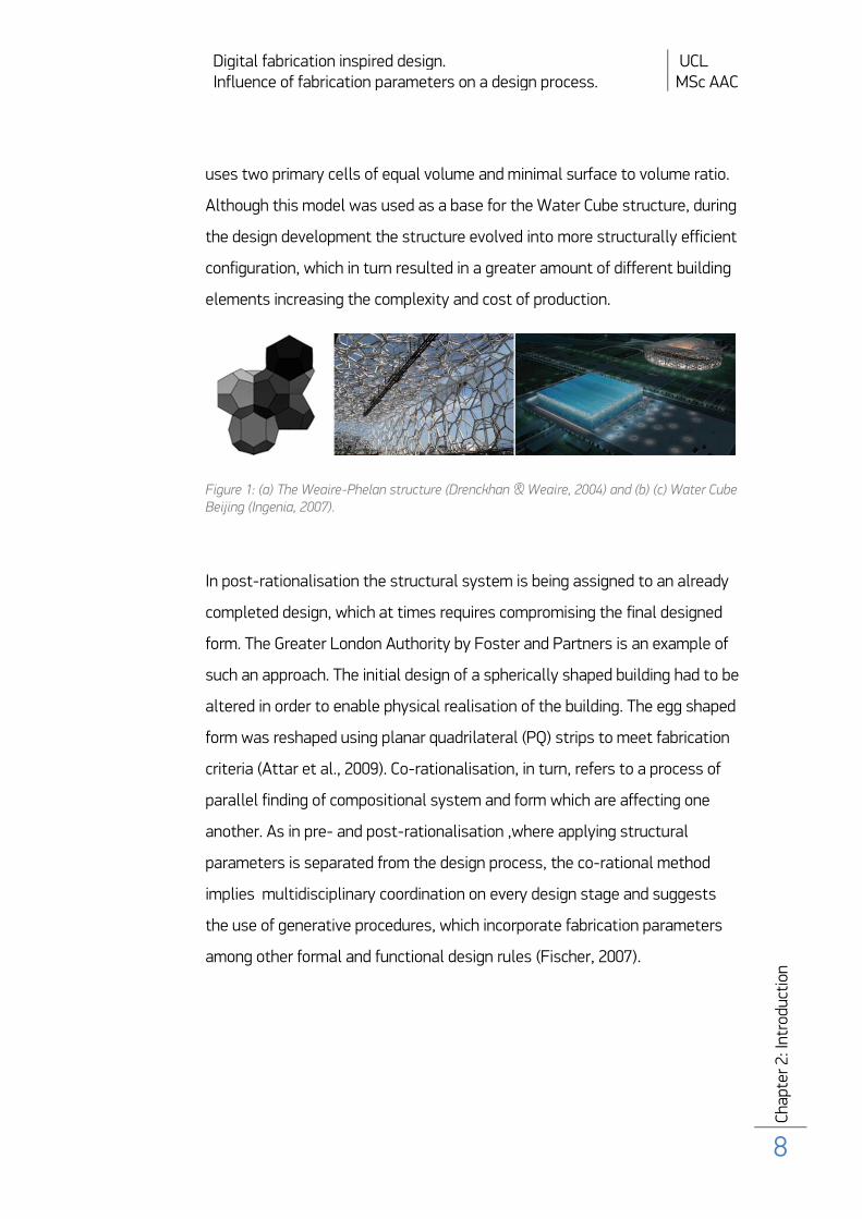
uses two primary cells of equal volume and minimal surface to volume ratio.
Although this model was used as a base for the Water Cube structure, during
the design development the structure evolved into more structurally efficient
configuration, which in turn resulted in a greater amount of different building
elements increasing the complexity and cost of production.
Figure 1: (a) The Weaire-Phelan structure (Drenckhan & Weaire, 2004) and (b) (c) Water Cube Beijing (Ingenia, 2007).
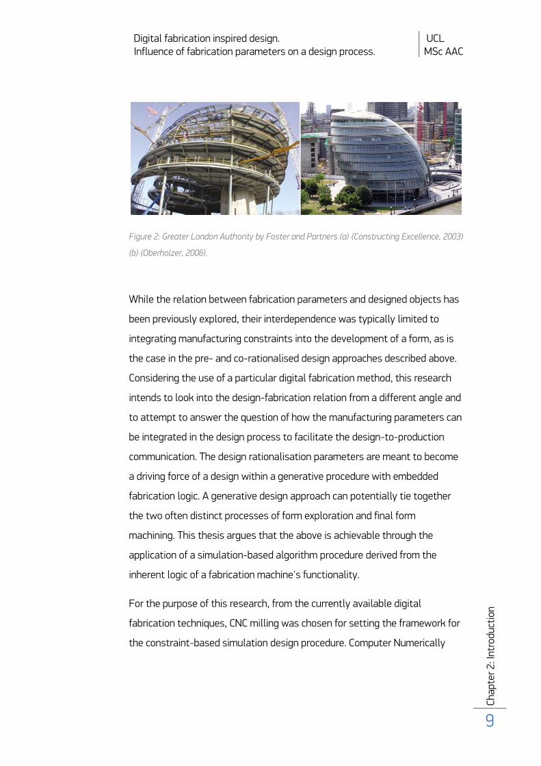
In post-rationalisation the structural system is being assigned to an already
completed design, which at times requires compromising the final designed
form. The Greater London Authority by Foster and Partners is an example of
such an approach. The initial design of a spherically shaped building had to be
altered in order to enable physical realisation of the building. The egg shaped
form was reshaped using planar quadrilateral (PQ) strips to meet fabrication
criteria (Attar et al., 2009). Co-rationalisation, in turn, refers to a process of
parallel finding of compositional system and form which are affecting one
another. As in pre- and post-rationalisation ,where applying structural
parameters is separated from the design process, the co-rational method
implies multidisciplinary coordination on every design stage and suggests
the use of generative procedures, which incorporate fabrication parameters
among other formal and functional design rules (Fischer, 2007).
Digital fabrication inspired design. UCL Influence of fabrication parameters on a design process. MSc AAC
Cha
pter
2: I
ntro
duct
ion
9
Figure 2: Greater London Authority by Foster and Partners (a) (Constructing Excellence, 2003)
(b) (Oberholzer, 2006).
While the relation between fabrication parameters and designed objects has
been previously explored, their interdependence was typically limited to
integrating manufacturing constraints into the development of a form, as is
the case in the pre- and co-rationalised design approaches described above.
Considering the use of a particular digital fabrication method, this research
intends to look into the design-fabrication relation from a different angle and
to attempt to answer the question of how the manufacturing parameters can
be integrated in the design process to facilitate the design-to-production
communication. The design rationalisation parameters are meant to become
a driving force of a design within a generative procedure with embedded
fabrication logic. A generative design approach can potentially tie together
the two often distinct processes of form exploration and final form
machining. This thesis argues that the above is achievable through the
application of a simulation-based algorithm procedure derived from the
inherent logic of a fabrication machine's functionality.
For the purpose of this research, from the currently available digital
fabrication techniques, CNC milling was chosen for setting the framework for
the constraint-based simulation design procedure. Computer Numerically
Digital fabrication inspired design. UCL Influence of fabrication parameters on a design process. MSc AAC
Cha
pter
2: I
ntro
duct
ion
10
Controlled milling machines are the most accessible and widely used in
architectural and construction industries since they are capable to produce
complex highly differentiated building elements in a relatively simple and
cost effective process. Their basic principle is based on a numerically
controlled drilling process and, depending on the number of axis in a machine,
also turning of either the machine’s head or/and the milled material. CNC
machines are automatically controlled by programmed commands of
Numerical Control programming language, also called G-Code thanks to the
functions syntax. The NC program, apart from the general purpose machine’s
operation control functions, consists of additional commands related to the
overall machine’s actions - the so-called M-codes, which may differ in
structure for particular machine model and producer. Although the majority
of NC programs are created by CAM software, they can be also developed by
the programmers directly. Because the tool path planning difficulty increases
exponentially with the increased number of supported axis, the manual
programming is limited to three axis machines, which are the most commonly
used. They operate in three dimensions using X, Y, Z axis only, enabling
sculpting landscaped surfaces with depth variation in Z axis, but only the
higher dimensional machines are capable of cutting more complex geometry.
The research here described is divided into two separate, but equally
important phases, both of which are created with the use of and for
programming language Processing 1.0.1. At first, a vast exploration was
made on finding a way of converting any given geometry from the Application
Programming Interface into milling machine preparatory code, which would
then be exported from the programming environment directly to the machine
controllers. At this stage a custom-made library for Processing was
developed in order to enable immediate transition from digital to physical
models using a 2,5 or 3 axis milling machines. Certain aspects of path
Digital fabrication inspired design. UCL Influence of fabrication parameters on a design process. MSc AAC
Cha
pter
2: I
ntro
duct
ion
11
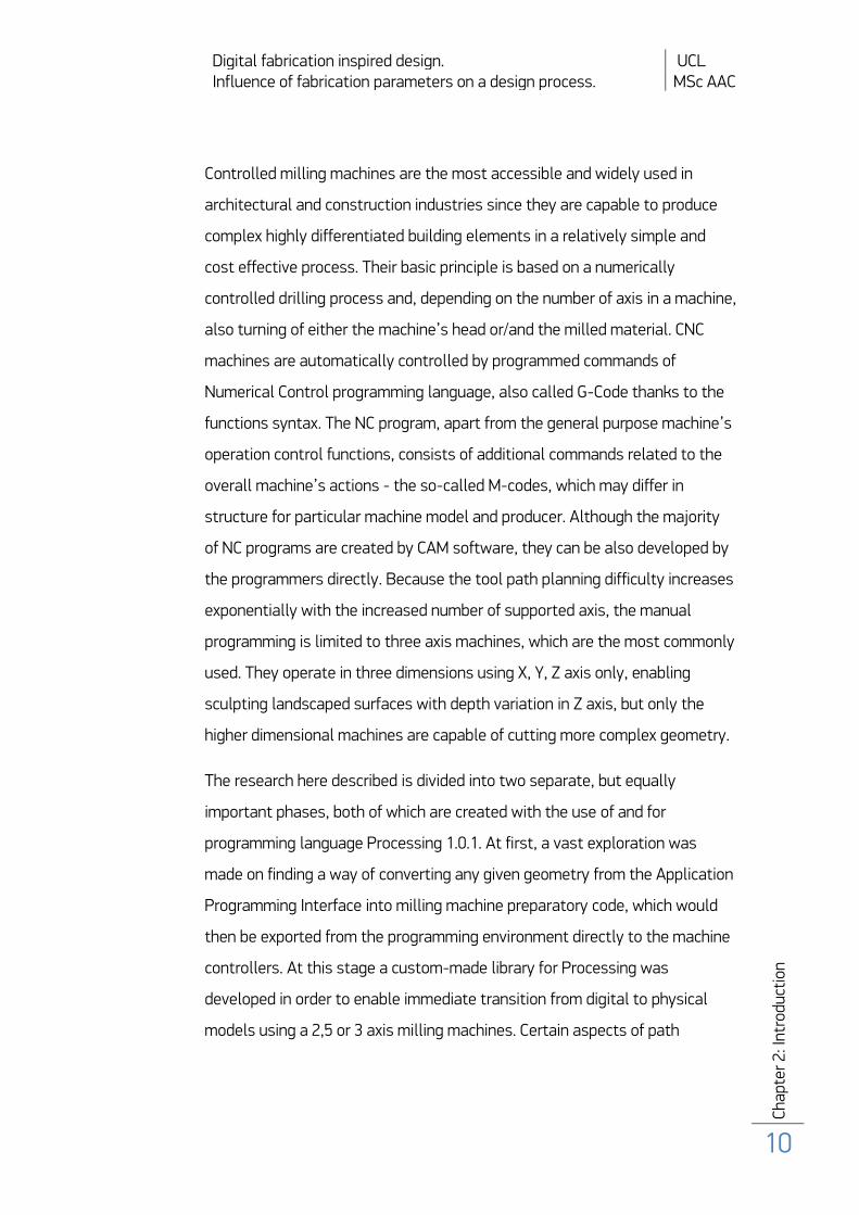
planning and optimisation were taken into account and were applied by the
means of genetic algorithm. Subsequently, a generative simulation-based
design procedure was created with the procedural logic incorporated from
five axes CNC milling machine and, in particular, the one with three
transitional axis and two rotary ones attached to a tilting rotary table. The
principles implemented in the first stage of the research were further
developed in the second one and thereafter applied to a particular design
problem.
Figure 3: (a) 3-axis CNC milling machine (b) 5-axis vertical milling machine (Mahanoy, 2008).
Digital fabrication inspired design. UCL Influence of fabrication parameters on a design process. MSc AAC
Cha
pter
3: B
ackg
roun
d
12
Background
3.1 Design vs. fabrication technologies
The research presented in this dissertation concentrates on the
interdependence of computer generated designs and the fabrication
processes that succeed . They have already been a subject of substantial
research both separately and in relation to one another. Widely discussed by
Klinger (2001) the tendency throughout architectural history of inevitable
close connectedness between mainstream building forms and at that time
available construction technologies and materials underlie the formulation of
these thesis objectives. Architecture’s dependence on many other fields of
knowledge and industry, especially construction industry and material
development, results in its parallel and conditional evolution. Achievements
in building technology are subsequently adopted to architectural solutions
withal. Klinger refers in his paper to Le Corbusier’s statement that “almost
every period of architecture has been linked to research in construction”
(1931) and describes how building industry achievements influenced the
creation of architectural forms from the medieval to present times. Similar
relations occur between stonemason craft and the form of medieval
cathedrals as in contemporary skin-and-bones buildings and digital
fabrication technologies. Although modern manufacturing methods allow
construction of nearly every form which can be generated by computer
visualisation software, there is a fundamental drawback of using this
approach into designing. Visualisation software is capable of developing and
immediately adjusting complex skin forms of buildings which can be created
with the aid of interactive algorithmic or scripting tools - often incorporated
in the software environment - thus enhancing the direct communication
between the designer and the generated form. However, the majority of the
Digital fabrication inspired design. UCL Influence of fabrication parameters on a design process. MSc AAC
Cha
pter
3: B
ackg
roun
d
13
above mentioned design tools incorporate neither physical properties of
materials and environment nor the fabrication restrictions while providing
easy to use file-to-factory communication functions. In order to fully take
advantage of the currently available design and manufacturing techniques,
the use of comprehensive design environment is suggested as a way of
overcoming laid down design issues. Alongside the aforementioned
discourse, Klinger also discusses the changing role and work spectrum of the
designer - to whom he refers as to the craftsperson - in the past and
nowadays. As in the industry age, when the designer had to combine design
skills and building technology, these requirements are also nowadays
expanding to the areas of computer modelling, visualisation skills and digital
fabrication processes knowledge. Nevertheless, the designer is expected to
be specialised in more and more disciplines, his work is nowadays largely
dependent on software developers and programmers. It can be concluded
that a skilled craftsperson in the digital era should also acquire programming
knowledge concurrently with the primary design skills in order to bind the
entire building’s or object’s development process by creating custom
comprehensive environments for specific design scenario.
Not only can digital fabrication techniques be used for producing
individual custom building elements or small scale models but also, as
Bonwetsch et al. mentions to conduct the whole building process of – in this
particular case – a parametric brick wall (2006). The computer-controlled
manufacturing technologies originally developed for and used in other
industries, e.g. in the automotive bile and aviation industries, open a window
of opportunity to adopt them in modern architectural contexts in wide range
of applications. The capability of such machines to perform highly complex
precise assignments is usually still limited to executing repetitive tasks in
the fully automated production lines. Digitally controlled machines’
Digital fabrication inspired design. UCL Influence of fabrication parameters on a design process. MSc AAC
Cha
pter
3: B
ackg
roun
d
14
customisability could be utilised for creating unique mass-customised
architectural forms. However, this kind of co-action requires developing
specialised software and hardware for a particular design instance, as there
is no general purpose CAD/CAM software for industrial all-purpose robots
available.
The DFab research laboratory DFab, opened by Gramazio and Kohler
in ETH, the Swiss Federal Institute of Technology in Zurich, aims to
investigate the possibilities of informing designs with digital data by building
big scale architectural prototypes with the use of a six axis industrial robot
(2008). Within four years they have developed a series of commercial and
academic experimental design procedures for building unique architectural
elements.
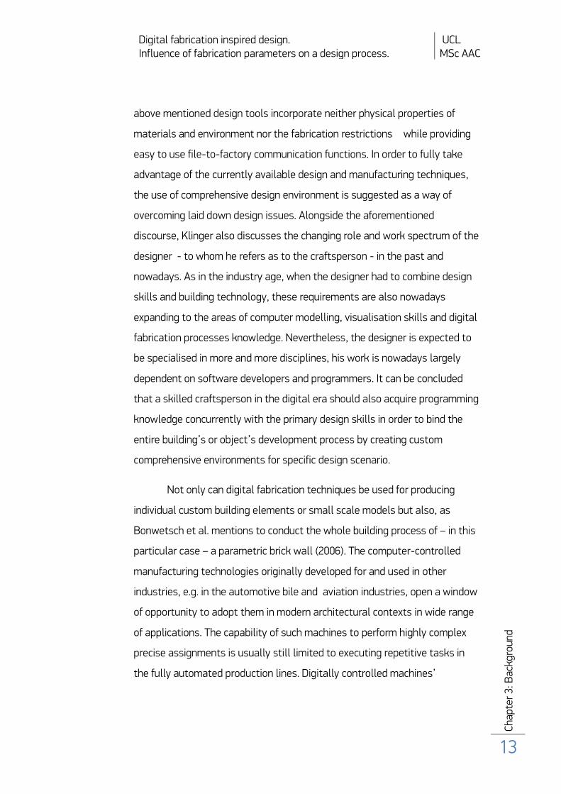
One example of such experimental design approach developed in DFab is the
“Programmed Wall” project, which examines digital additive fabrication
technique in the design context (Bonwetsch et al., 2006).
Figure 4: The programmed wall project by DFab Laboratory (Gramazio & Kohler, 2006).
In this project parametric tools were utilised for generating two by three
meters sized parametrically controlled wall designs composed of standard
brick units. On account of using common construction material, the design
process was intended to concentrate mainly on the construction technique
rather than on material properties. A number of prototypes were constructed

Digital fabrication inspired design. UCL Influence of fabrication parameters on a design process. MSc AAC
Cha
pter
3: B
ackg
roun
d
15
by the robot that is capable of reaching every point in a 3x3x8 meters space.
The design information was used to create the so-called informed
architecture, which is a result of directly linking design information with real
architectural artefacts. Creating such unique architectural elements has
become possible via creation of custom software and hardware tools for each
particular exercise. Firstly a design method in MAYA software scripting
environment was developed and secondly a post-processing script was
created for translation of the output CAD models into robot specific
procedural language. Also, a custom-made brick gripper robot’s extension
was built, which at further stages of the project was enhanced with a precise
adhesive automated adhesive depositing onto each brick. This method was
successfully adopted in a commercial architectural application for
constructing a Winery facade in Fläsch with total surface area of 400 sq
meters.
Figure 5: Facade Gantenbein Winery, Fläsch, (Switzerland (Gramazio & Kohler, 2006).
3.2 Digital manufacturing processes
Except the already mentioned additive digital fabrication principles, two other
main types exist: subtractive and formative classified in respect of material
formation rules. The machines used typically for each of the distinct
processes include: stereolithography (additive), CNC milling or laser cutting
(subtractive) and press brake (formative). Each of the listed types has its
Digital fabrication inspired design. UCL Influence of fabrication parameters on a design process. MSc AAC
Cha
pter
3: B
ackg
roun
d
16
specific implications and limitations. As for the subtractive process the
problem is the waste material that is generated during the production, which
is not the case if of the other techniques, is employed. Furthermore the
additive type processes prove to be much more expensive and time
consuming for building even small scaled objects, when compared with for
example CNC milling method, which is much more economically efficient for
building trial objects and prototypes. Stereolithography should, therefore, be
reserved for creating mostly final objects. Industrial multi-purpose robots as
contrasted with small digital fabrication machines are capable of executing a
whole range of tasks, and thus have a great potential for multi-requirement
architectural applications.
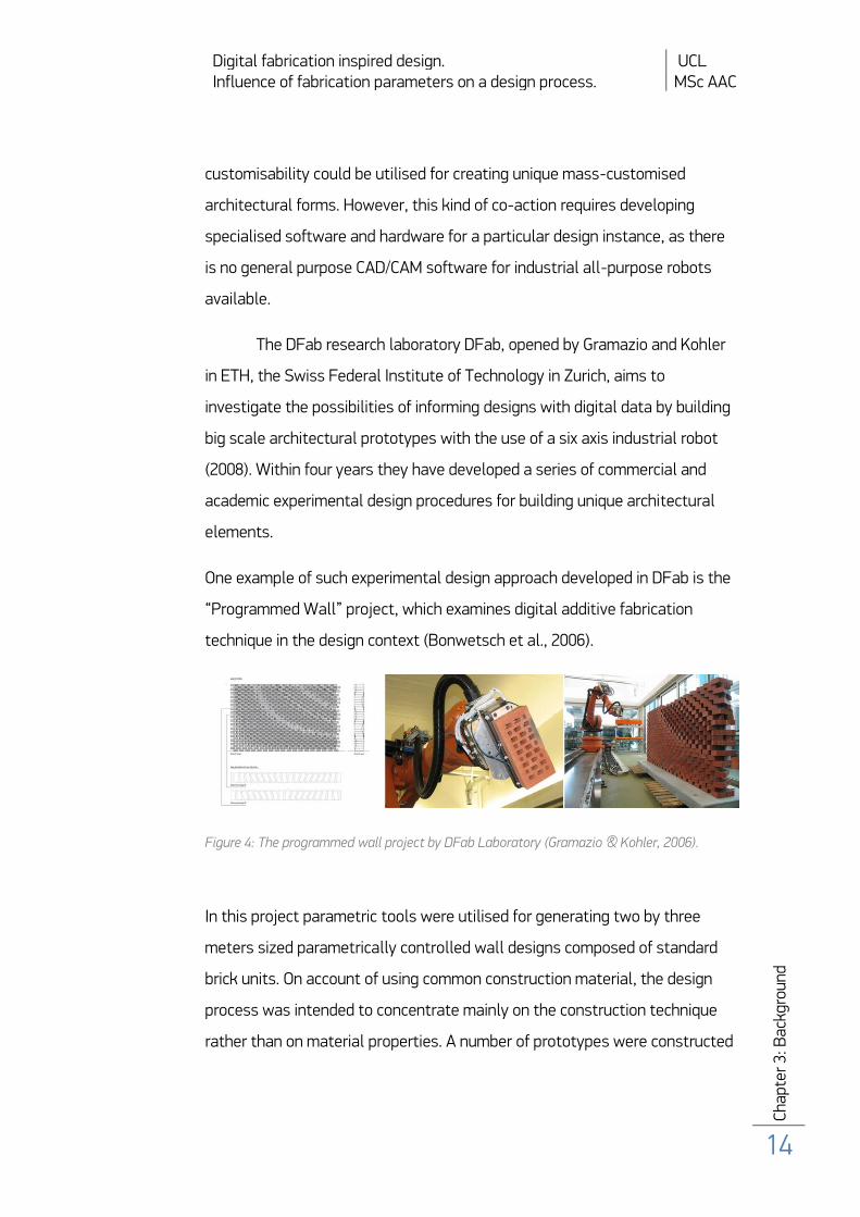
The selfsame robot used for constructing “The programmed wall” project’s
prototypes was also used in another study design instance conducted in
DFab Laboratory in ETH Zurich. Here in “The perforated wall”, in turn, the
subtractive method was implemented for creating full–scale perforated wall
components also developed with the aid of parametric software (Gramazio &
Kohler, 2008). Individual holes were defined by X and Y coordinates, radius
and two angles – one related to the wall’s mass material and another with
pivot point in the centre of each perforation. This approach, although limiting
the design expressions to manipulation of a single element, provided with a
wide variety of output forms. Yet the designs were purely based on visual
qualities and - at this stage of the project - no higher purpose of wall panels
such as shading or visual connectedness, was considered. The following
research led to load bearing properties testing of a fabricated concrete
perforated wall. Still, this property was not taken into account during the
process of generating perforation patterns and was only tested thereafter.
The two described projects from DFab Laboratory present an advanced
approach to architectural design by incorporating bespoke developed
Digital fabrication inspired design. UCL Influence of fabrication parameters on a design process. MSc AAC
Cha
pter
3: B
ackg
roun
d
17
hardware and software tools, implementation of which informed the
architectural form and led to construction of unique objects unobtainable by
standard design and construction procedures. There is no imperative
requirement for single multi-purpose software development. However a
comprehensive tool could tie together dispersed design-to-fabrication
elements. This research intends to investigate the possibilities of
implementing of such an approach in design process and study the
consequential enhancement potential.
Figure 6: The perforated wall 1 & 2 by DFab Laboratory (Gramazio & Kohler, 2006).
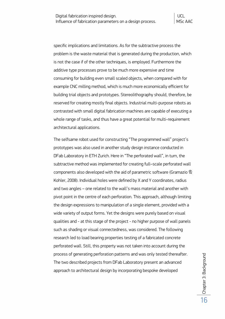
3.3 Economic factor
The subtractive manufacture method, especially CNC milling, has recently
gained new applications in architecture, which is caused by its low cost and
time fabrication efficiency properties. Three- or more axis milling machines
for instance can be used for forming concrete moulds of non-standard
building elements (Kolarevic, 2006), as it was conducted in the construction
of Zollhof Towers in Düsseldorf, Germany by Frank Gehry (2000).
Materialisation of the design necessitated the creation of over 350 individual
facade elements, which were designed in the CATIA software. The non-
standard forms were milled in styrofoam by a numerically controlled machine
and then served as moulds for the reinforced concrete panels.

Digital fabrication inspired design. UCL Influence of fabrication parameters on a design process. MSc AAC
Cha
pter
3: B
ackg
roun
d
18
Figure 7: Styrofoam moulds milled by multi-axis milling machine for construction of Zollhof Towers (Afify & Elghaffar, 2007).
The implementation of digital fabrication technology does not necessarily
entail costly solutions. For example the “Instant House” project examines the
possibilities of designing low cost customised houses with the use of digital
fabrication methods (Botha & Sass, 2006). Based on the fabrication criteria
of two-dimensional plywood joints and with the parameters such as
building’s location, climate characteristic and stylistic variations an
automated parametric system generates forms, which can then be modified,
not only in building’s appearances but also in spatial and functional
properties also.
Figure 8: The implication on Instant House generative procedure (Botha & Sass, 2006).

Digital fabrication inspired design. UCL Influence of fabrication parameters on a design process. MSc AAC
Cha
pter
3: B
ackg
roun
d
19
The projects of Instant House and Zollhof Towers present two ideological
extremes of the applications of digital fabrication in architecture – by either
taking advantage of it in order to facilitate customisation of low cost
buildings or by using it for materialisation of complex irrational forms – they
both require tailored program’s development. The bespoke programming
tools assist in facilitating the essential communication between computed
aided designs and materialisation facilities.
3.4 Hardware – software correspondence
Typically, the transformation of digital information from visualisation
environment to procedural machine language is accomplished by the
CAD/CAM converting software, which tends to be highly processor and
memory-intensive even if working on high speed computers. Moreover, the
CAD/CAM software turns out to produce erratic programmes, therefore the
code verification by either simulation software or time-consuming and unsafe
trials becomes crucial. Additionally, relaying on CAD models geometry can
render to be troublesome due to an unavoidable inaccuracy and frequent
anomalies occurring in complex CAD geometries (McKenney, 1998). Many
efforts have been taken to find the appropriate algorithm for correcting and
thereafter converting CAD geometries into the fabrication machine language,
and thus overcoming the stated problems. The majority of solutions were
based on applying parametric surfaces to given geometry, which was a
correct approach for CAD geometries before the development graphics
acceleration hardware which enforced the use of non parametric geometries.
This shift in modelling tendencies becomes a prerequisite for more general
geometry analysis. Depth buffer solution provided with adequate results to
this problem, because by analysing every pixels’ position in the display
Digital fabrication inspired design. UCL Influence of fabrication parameters on a design process. MSc AAC
Cha
pter
3: B
ackg
roun
d
20
makes it possible to analyse and export data based on any given geometry
(Carter et al., 2008). This feature available in more advanced graphic cards as
a two dimensional array can be easily accessed from graphics Application
programming interface (API). Therefore the depth buffer function was
selected to be further exploited for the development of the programming
environment described in following chapter of this thesis.
3.5 Aspects of optimisation in design and fabrication
For the fabrication process to be efficient the generated tool trajectory often
requires subsequent optimisation to reduce redundant movements and the
thereby the cutting time. Shorter production process influences concurrently
the overall cost of the object and allow fabrication of greater number of
elements in the same time.
The optimisation of milling machines’ tool paths presents another complex
computational task, which is similar in principle to the travelling salesman
problem (TSP). The objective of this task is to find the shortest path for
visiting every city on the list only once and returning to the starting point
with the given numerical distances between every one city and all the other
as a given database. TSP belongs to the group of the NP-complete (which
stands for nondeterministic polynomial time) problems in the computational
complexity theory, which have two main properties: one is that every solution
to this problem can be quickly evaluated and the other is that if this problem
can be solved quickly then so can any other problem. TSP is an important
combinational optimisation problem which has not yet been entirely solved,
since the solution search time increases exponentially with the number of
nodes in the system. A great deal of publications and researches were
Digital fabrication inspired design. UCL Influence of fabrication parameters on a design process. MSc AAC
Cha
pter
3: B
ackg
roun
d
21
dedicated to the TS problem dealing with heuristic algorithms suitability and
the comparative performance of each search technique (Johnson & McGeoch,
1990). A particular study by Dorigo et al. in which the local search algorithms
such as: genetic algorithms, genetic programming, neural networks,
simulated annealing and ant colony search were compared showed the best
performance of the ant colony search (1997). Also a few successful
algorithms were created to specifically solve the TS problem, for instance the
Keld Helsgaun’s algorithm or the state-of-the-art Concorde TSP Solver by
David Applegate, Robert E. Bixby, Vašek Chvátal, and William J. Cook
(Montemanni et al., 2007).
The approximation algorithms tend to present close to optimal solutions for
the TSP in a relatively short time. Among others like an ant colony or neural
networks the evolutionary algorithms are the most commonly used for the
specific example of travelling salesman problem, which is the CNC milling
machine’s tool path planning and optimisation. Hasan et al. presented an
improved instance genetic algorithm for optimal collision-free path planning
in two dimensional spaces (2007). In his research he presents a highly
effective algorithm which renders better results than Voronoi diagram based
Bhattacharya and Gavrilova algorithm that has been already proven to
produce highly optimised paths (2007). Above described scientific studies
show that no specific accurate procedure exists that best suits tool
trajectory optimisation problem. Close to optimal and widely used for this
task genetic algorithm occurs to be suitable for implementation for the
purpose of this thesis.

Digital fabrication inspired design. UCL Influence of fabrication parameters on a design process. MSc AAC
Cha
pter
3: B
ackg
roun
d
22
Figure 9: Genetic algorithm TSP optimisation (Saiko, 2005).
3.6 Aims and objectives
Although recently the evolutionary algorithms are being introduced in
architectural practice as method for structural optimisation, the most
dominantly EA in design are used as an experimental tool for form
generation. The evolutionary algorithms’ application as optimisation
technique is therefore limited to post-rationalisation of a building structure
and its potential for comprehensive implementation in design-related
disciplines is still to be explored. Undoubtedly, genetic algorithmic strategies
present the capability for joining together all of the aforementioned
implementations in relation to architectural processes of design, optimisation
and fabrication into one multi-objective design environment. This study,
however, focuses predominantly on the exploration of the new design
possibilities that arise from the digital fabrication technologies rather than on
the manufacturing process optimisation or automation itself. The aspects of
path planning are incorporated in greater extent in the first stage of this
research, whilst the following design implementation stage concentrates
largely on link between design and digital manufacturing
Digital fabrication inspired design. UCL Influence of fabrication parameters on a design process. MSc AAC
Cha
pter
4: P
hase
1 –
Init
ial A
naly
sis
23
Phase1 - Methodology
4.1 G-Code export function and language syntax
The initial phase of this study constitutes the study of the correlation
between a virtual model and a fabrication procedure of physical objects -
from two dimensional images to three dimensional object analysis. This
research phase has led to the development of a bespoke tool for exporting
procedural code from Processing programming environment in order to
directly execute the fabrication process of the designed objects on a CNC
milling machine. At the outset the G-Code language syntax and principles will
be introduced.
The G-Code is a low-level universal procedural language for CNC
machines, the commands of which constitute the main body of Numerical
Control programs. The G-Code functions refer immediately to the milling or
cutting operations of the machine. The most commonly used functions
include among others: G00 – rapid positioning of the tool without milling, G01
– linear interpolation to given point coordinates, G02 – circular clockwise
interpolation, G10 – setting the coordinate origin system, G41 – cutter radius
compensation left of path (Appendix 1). The remaining functions of NC
programs include the M-functions responsible for machine comprehensive
behaviour, T-functions refer to tool handling, S – to spindle speed setting, F-
to feed rate, X, Y, Z – to absolute coordinates, finally A and B refer to two
rotary angles for up to 5-axis milling machine handling (a simple G-Code
program example for cutting a letter M is presented in Appendix 2). Although,
the number of available G-Code commands has grown in number to support
complex shaped tool paths programmed solely in NC language, the library
described below employ only few basic functions. This is the result of a

Digital fabrication inspired design. UCL Influence of fabrication parameters on a design process. MSc AAC
Cha
pter
4: P
hase
1 –
Init
ial A
naly
sis
24
generalised approach to the problem and the aim of creating an effective
algorithm for good approximation of the input geometry.
4.1.1 Two dimensional image analysis
As the ascendant exercise of G-Code export handling in higher dimensions, a
flat image processing procedure was created based on colour analysis. For
vector drawing conversion it required specification of exact colours
corresponding with the engraving and full depth cuts. Concurrently the
referring depths were specified. Similar conversion procedure is executed by a
typical converter for a laser cutter. For the raster image G-Code export, the
depth of the engraving is correlated with each pixel’s colour brightness. Flat
images are in this way converted into spatial relief, which depth is based on
pixels’ colours. The brightness values are stored in an array along with the
corresponding pixels’ positions in the display, thus creating a list of path
coordinates.
Figure 10: Raster image and its 3d representation created by colour brightness analysis.

Digital fabrication inspired design. UCL Influence of fabrication parameters on a design process. MSc AAC
Cha
pter
4: P
hase
1 –
Init
ial A
naly
sis
25
The cut depth depends on material dimensions, as the brightness values are
brought into a range of material thickness value:
PVector pos = new PVector(j,i, (mat_height-
(brightness(get(j,i))/255*mat_height)));
positions.add(pos);
The NC program starting and ending commands depend on the machine’s
type. Usually the starting functions include the tool selection, spindle speed
and feed rate settings:
lines = append(lines,"T1M6" ); - select tool
lines = append(lines,"M03 S2345 F100"); - spindle speed:2345, feed rate: 100
The array of positions is thereafter converted into a string of G-Code
functions with vector coordinates as guiding points:
PVector vec = positions.get(i);
lines = append(lines,"G01 X " + vec.x + " G01 Y "
+ vec.y + " Z-" + vec.z);
Once the array of vector positions is created, the G-Code file can we written.
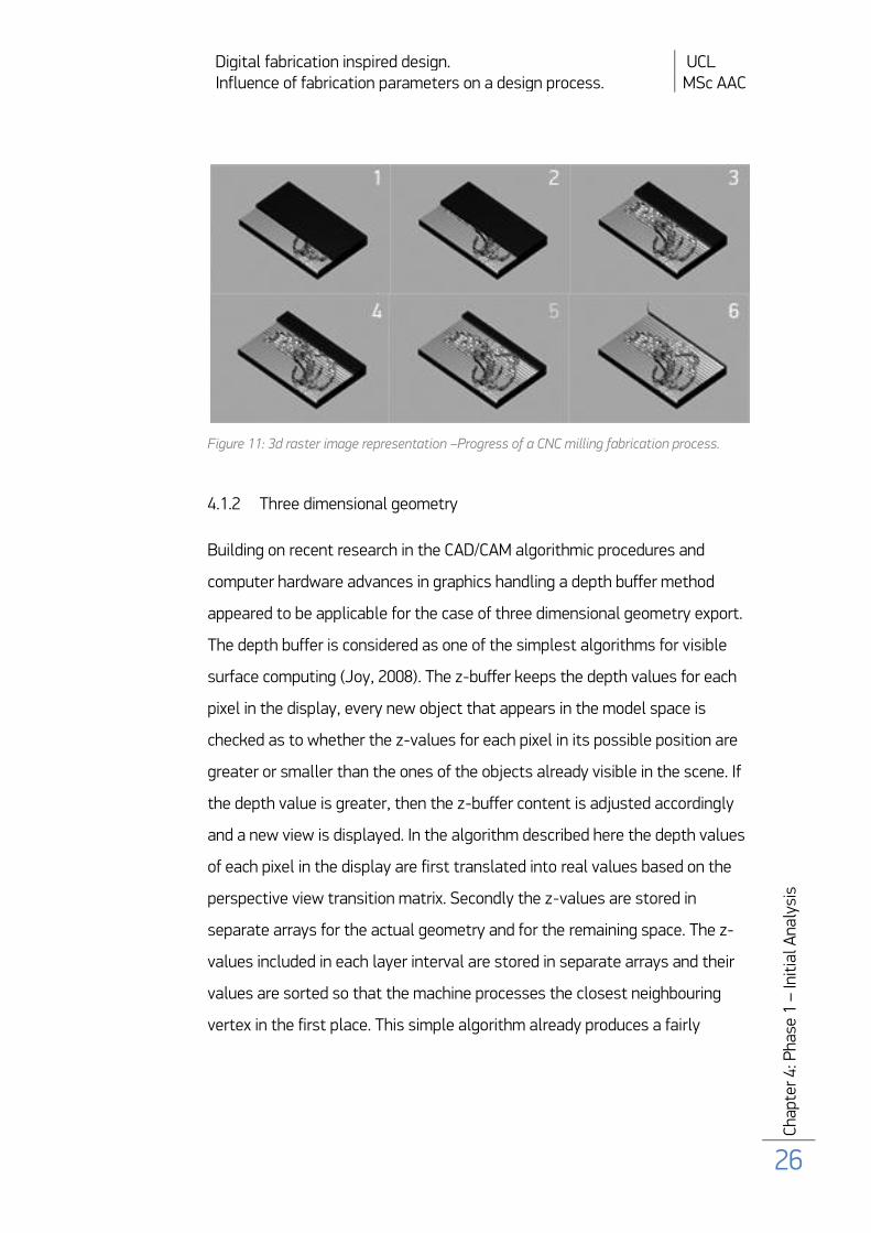
The exported code proved to successfully convert two dimensional images
into spatial representations, which was tested in the CNC simulation
software.
Digital fabrication inspired design. UCL Influence of fabrication parameters on a design process. MSc AAC
Cha
pter
4: P
hase
1 –
Init
ial A
naly
sis
26
Figure 11: 3d raster image representation –Progress of a CNC milling fabrication process.
4.1.2 Three dimensional geometry
Building on recent research in the CAD/CAM algorithmic procedures and
computer hardware advances in graphics handling a depth buffer method
appeared to be applicable for the case of three dimensional geometry export.
The depth buffer is considered as one of the simplest algorithms for visible
surface computing (Joy, 2008). The z-buffer keeps the depth values for each
pixel in the display, every new object that appears in the model space is
checked as to whether the z-values for each pixel in its possible position are
greater or smaller than the ones of the objects already visible in the scene. If
the depth value is greater, then the z-buffer content is adjusted accordingly
and a new view is displayed. In the algorithm described here the depth values
of each pixel in the display are first translated into real values based on the
perspective view transition matrix. Secondly the z-values are stored in
separate arrays for the actual geometry and for the remaining space. The z-
values included in each layer interval are stored in separate arrays and their
values are sorted so that the machine processes the closest neighbouring
vertex in the first place. This simple algorithm already produces a fairly

Digital fabrication inspired design. UCL Influence of fabrication parameters on a design process. MSc AAC
Cha
pter
4: P
hase
1 –
Init
ial A
naly
sis
27
optimised path. The more panoptical approach to path optimisation will be
discussed in the following chapter with the implementation of genetic
algorithm.
A simple pseudocode can be given for this particular implementation of z-
buffer:
Given
3d geometry
Orthographic projection
An array z-buffer[x,y]
begin
for each pixel (x,y) do {
calculate real values of z-buffer at (x,y)
calculate maximum value of z-buffer
if z-buffer[x,y] > max_buff then {
Object[x,y,z] = Vector (x,y,z_buffer[x,y])
}
}
Sort Object[x,y,z] and Background[x,y,z] by z Value
Create Layer_values (z)[x,y,z]
Calculate distance (me.Layer_values (z)[x,y,z], other.Layer_values (z)[x,y,z])
Create Compare_values [x,y,z,dist]
Sort by distance
Create Tool_path (z)[x,y,z]
Create String with G-Code functions [“G01 X” + x + “Y” + y]
end

Digital fabrication inspired design. UCL Influence of fabrication parameters on a design process. MSc AAC
Cha
pter
4: P
hase
1 –
Init
ial A
naly
sis
28
4.1.3 2,5 vs. 3 axis machine procedures
The differences between 2,5- and 3-axis milling machines lead to a distinct
treatment of tool path planning in both cases. The 2,5-axis machine is
capable of processing paths with simultaneous changes in only two from
three available axes, whereas 3-axis machines are able to coordinate all the
three axis at the same time. This characteristics results in different
smoothness levels achievable by both types of machines. In the first case
only the paths programmed in layers can be fabricated, the more complex
trajectories are applicable to 3- and above milling machines only. This
constraint is partially overcome by dividing the milling process into two
phases: rough material subtraction and final finishing. The initial cut is
executed with fixed Z axis, the detailed cut with fixed either X or Y axis.
However, complex circular and curved movements in three dimensions are
still inoperable, the manufactured models present adequate level of
accuracy.
Figure 12: Two phases of 2,5-axis milling machine: (1) roughing, (2) finishing
Digital fabrication inspired design. UCL Influence of fabrication parameters on a design process. MSc AAC
Cha
pter
4: P
hase
1 –
Init
ial A
naly
sis
29
4.2 The Library (PGCode3D)
The proceeding study on G-Code export function resulted in the development
of a library – an external set of commands originally not available for use in a
particular software - created for Processing 1.0.1. The library enables a user
to easily export preparatory code for 2,5- and 3-axis milling machine in .nc
and g00 files. The library definition requires specification of few basic
parameters – up to two tool diameters, thickness of material and output file
name.
import PGCode3D.*; - import library
G_code_export gc;
gc = new G_code_export (this, 12.7, 6, "output", 50); - class definition [T1 –
12.7 mm, T2 – 6mm, material thickness – 50mm]
gc.print_data(); - model information printout [at the end of void draw]
gc.export(); - export function [at the end of void draw]
4.2.1 Levels of approximation
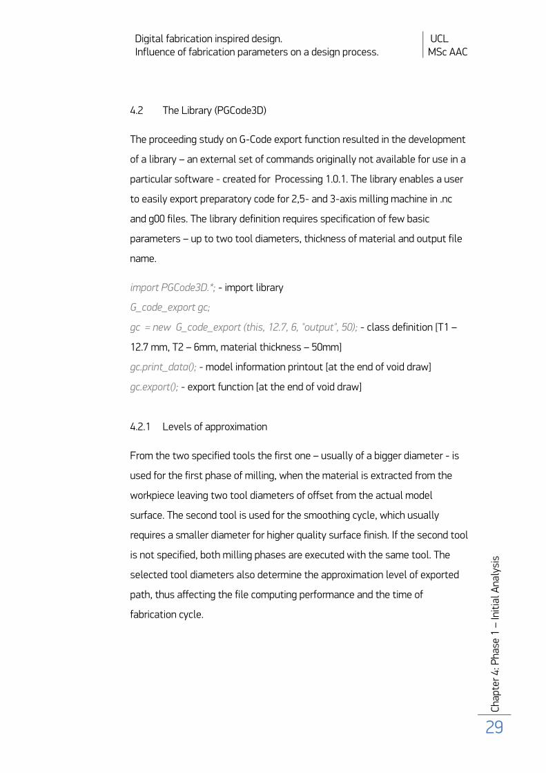
From the two specified tools the first one – usually of a bigger diameter - is
used for the first phase of milling, when the material is extracted from the
workpiece leaving two tool diameters of offset from the actual model
surface. The second tool is used for the smoothing cycle, which usually
requires a smaller diameter for higher quality surface finish. If the second tool
is not specified, both milling phases are executed with the same tool. The
selected tool diameters also determine the approximation level of exported
path, thus affecting the file computing performance and the time of
fabrication cycle.
Digital fabrication inspired design. UCL Influence of fabrication parameters on a design process. MSc AAC
Cha
pter
4: P
hase
1 –
Init
ial A
naly
sis
30
Figure 13: Fabrication study model #2, (a-b) roughing cycle, (c) finishing cycle
4.2.2 Stock and model dimensions
The discrepancy between the model size and maximum machine
working height is very likely to occur. The library will produce part files for
virtual models which are exceeding the specified material height in order to
fabricate the object in separate pieces. Nonetheless, whenever the material
dimensions are not specified the whole geometry is exported as a single file.
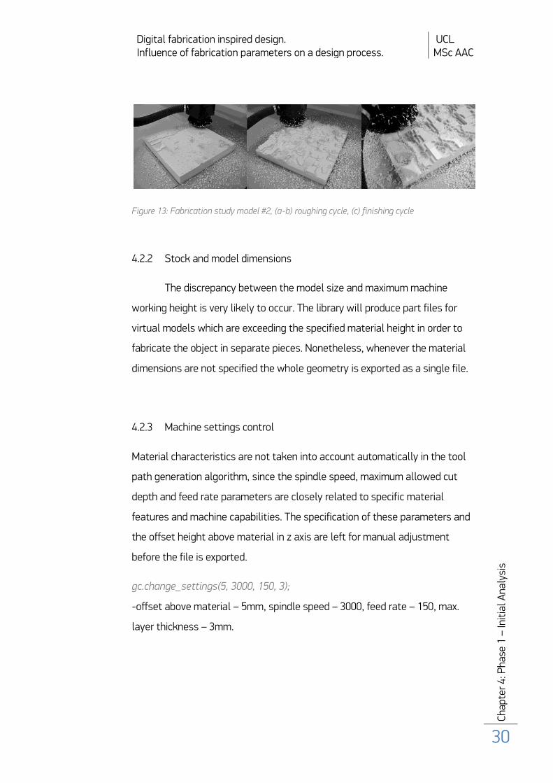
4.2.3 Machine settings control
Material characteristics are not taken into account automatically in the tool
path generation algorithm, since the spindle speed, maximum allowed cut
depth and feed rate parameters are closely related to specific material
features and machine capabilities. The specification of these parameters and
the offset height above material in z axis are left for manual adjustment
before the file is exported.
gc.change_settings(5, 3000, 150, 3);
-offset above material – 5mm, spindle speed – 3000, feed rate – 150, max.
layer thickness – 3mm.
Digital fabrication inspired design. UCL Influence of fabrication parameters on a design process. MSc AAC
Cha
pter
4: P
hase
1 –
Init
ial A
naly
sis
31
Figure 14: Fabrication study model #1, (b) collision between machine's head and material .
4.2.4 Application coding requirements
Both P3D and OpenGL renderers available in Processing are supported by the
library. Relevant code sections demonstrating depth buffer handling in both
cases are presented in Appendix 3. It is worth mentioning that the depth
buffer readings forbid use of colour transparency and text fields in the scene,
as it may cause faulty readings of z-buffer. It is also required to use
orthographic projection to prevent processing of perspective distorted
geometry – otherwise the ortho function will be applied automatically by the
library without the possibility of control over projection shifting, as it occurs
in P3D renderer for example.
4.2.5 Path optimisation (Genetic Algorithm)
The tool path produced by the above described procedure exhibits some level
of optimisation, solely by the implemented vector positions’ sorting
procedure. Nevertheless, it appeared that the overall performance of the
algorithm could be improved by adding the option of proper path
optimisation. The genetic algorithm was selected on account of the
discussed possibility of utilising single algorithmic procedure for
Digital fabrication inspired design. UCL Influence of fabrication parameters on a design process. MSc AAC
Cha
pter
4: P
hase
1 –
Init
ial A
naly
sis
32
accomplishing stated goals of form generation and object optimisation linked
with the fabrication parameters in one comprehensive design environment.
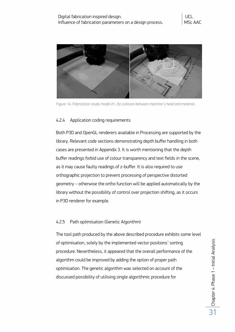
Figure 15: (1) layer by layer material subtraction and (2) smoothing trajectory aligned to model surface created by a basic sorting algorithm.
First, a simplified optimisation procedure was tested. In this case the
genotype was governing the starting point of tool path on every layer by
turns. The selected initial coordinates influence the whole generated path by
the sorting procedure. This optimisation exhibits a good degree of
improvement. However, some problem arises when the milled surface is very
craggy then the layer based path planning is unreasonable due to the amount
of redundant jumps between separate wells.
gc.optimise_path(4000); - 4000 of generations to be optimised
Another optimisation procedure, although potentially more efficient,
did not prove to produce more optimised paths. The algorithm was searching
the entire array of tool path positions and was each time searching for the

Digital fabrication inspired design. UCL Influence of fabrication parameters on a design process. MSc AAC
Cha
pter
4: P
hase
1 –
Init
ial A
naly
sis
33
closest vertex. Still the important requirement was to cut the higher Z values
in the first place. At first sight the output path exhibited a potential of a
shorter path being computed, as the machine was not extracting material
layer by layer - as it was happening in the previous optimisation procedure -
but this time was milling in some kind of clusters. Yet, the time
measurements did not confirm that first impression. A more advanced
algorithmic approach would therefore be imperative in order to generate
highly optimised accurate NC programmes.
Digital fabrication inspired design. UCL Influence of fabrication parameters on a design process. MSc AAC
Cha
pter
4: P
hase
1 –
Init
ial A
naly
sis
34
Phase1 - Results
4.3 Implementation and optimisation results
A number of study models were built to test the default library
parameters, the approximation interval and path outcome performance in a
real life scenario. The interim development stages were tested in simulation
software only to prevent machine and material damages before the
appropriate code was computed. The code was tested exclusively on one
machine and a further development of the library requires testing on various
machine types, which presumably will lead to necessary altering of the code
initial and closing M-code functions.
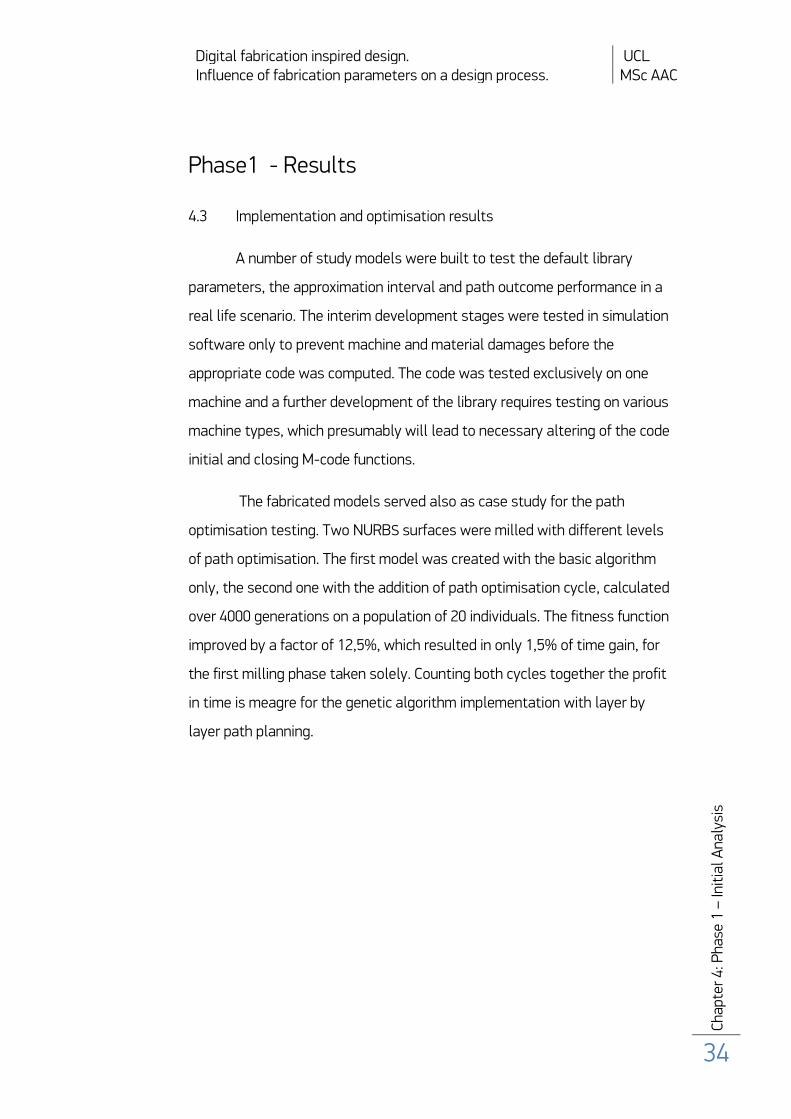
The fabricated models served also as case study for the path
optimisation testing. Two NURBS surfaces were milled with different levels
of path optimisation. The first model was created with the basic algorithm
only, the second one with the addition of path optimisation cycle, calculated
over 4000 generations on a population of 20 individuals. The fitness function
improved by a factor of 12,5%, which resulted in only 1,5% of time gain, for
the first milling phase taken solely. Counting both cycles together the profit
in time is meagre for the genetic algorithm implementation with layer by
layer path planning.
Digital fabrication inspired design. UCL Influence of fabrication parameters on a design process. MSc AAC
Cha
pter
4: P
hase
1 –
Init
ial A
naly
sis
35
Figure 16: Fabrication study model #3, optimisation efficiency testing.
Optimisation performance was thereafter tested on different model sizes and
surface shapes. The performance of initial optimisation algorithm strategy
presented good fitness value improvement. Maximum achieved enhancement
ratio equals 28% for machining of a NURBS surface of 30x30x5 cm size,
calculated with 12.7 mm tool diameter for the optimised material disposal
cycle. The genetic algorithm was evaluating a population of 20 individuals
over 3000 generation. The optimisation process was terminated once there
was no more fitness value improvement over 500 generation. Achieved
fitness improvement equals to 3% of machine working time yield. These
results prove that there is a strong correspondence between the actual
model form and optimisation efficiency.
4.4 Computation performance
The adopted geometry analysis principle has proven to output good-
approximation of any virtual models, which, for the given purpose of digital
fabrication experimentations and models production appears to be sufficient
at this stage of the research.

Digital fabrication inspired design. UCL Influence of fabrication parameters on a design process. MSc AAC
Cha
pter
4: P
hase
1 –
Init
ial A
naly
sis
36
Figure 17: Tool paths and model surface in (1) roughing cycle and (2) smoothing cycle
The models up to 50x50x50 cm are easily processed in a satisfactory time (up
to few minutes). The time required for file computation is inevitably
dependent on the model size and diameters of specified tools, which define
the vertex step (precisely half of the diameter size). Diameter of the first tool
used for initial milling stage of material subtraction influences concurrently
the optimisation parameters, as this is the algorithmically optimised phase of
the process. The second cycle proceeds in the so-called slices along Y or X
axis and follows all the vertices one after the other without any tool jumps.
In the smoothing phase it is advised to apply smaller diameter tools and
slower feed rate for more satisfactory results of surface finishing.
Digital fabrication inspired design. UCL Influence of fabrication parameters on a design process. MSc AAC
Cha
pter
5: P
hase
2 –
Des
ign
appl
icat
ion
37
Phase 2 – Methodology
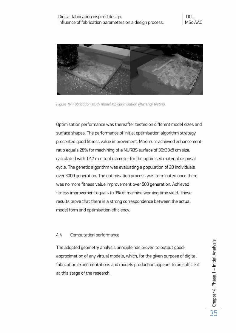
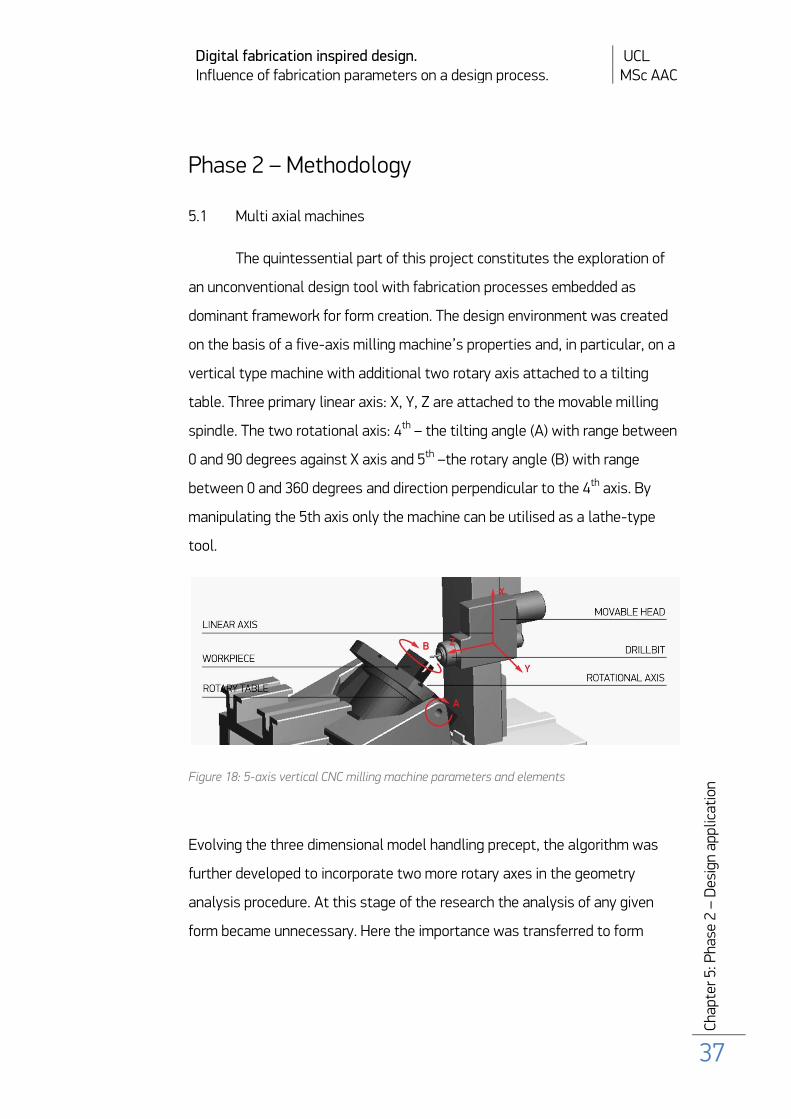
5.1 Multi axial machines
The quintessential part of this project constitutes the exploration of
an unconventional design tool with fabrication processes embedded as
dominant framework for form creation. The design environment was created
on the basis of a five-axis milling machine’s properties and, in particular, on a
vertical type machine with additional two rotary axis attached to a tilting
table. Three primary linear axis: X, Y, Z are attached to the movable milling
spindle. The two rotational axis: 4th – the tilting angle (A) with range between
0 and 90 degrees against X axis and 5th –the rotary angle (B) with range
between 0 and 360 degrees and direction perpendicular to the 4th axis. By
manipulating the 5th axis only the machine can be utilised as a lathe-type
tool.
Figure 18: 5-axis vertical CNC milling machine parameters and elements
Evolving the three dimensional model handling precept, the algorithm was
further developed to incorporate two more rotary axes in the geometry
analysis procedure. At this stage of the research the analysis of any given
form became unnecessary. Here the importance was transferred to form
Digital fabrication inspired design. UCL Influence of fabrication parameters on a design process. MSc AAC
Cha
pter
5: P
hase
2 –
Des
ign
appl
icat
ion
38
exploration mainly, thus sustaining the identical principles for dealing with
geometry. Herein the depth buffer values are no longer stored only as
physical model vertexes, of which the negative form is to be milled, but the
actual readings determine which parts of a virtual black of material are
available for milling subtraction. However, these values are still used for
further physical model creation, but at the first stage of described procedure,
which is the form finding process, these readings are used primarily for
subtractive digital object generation. The design environment is set as a
virtual fabrication machine driven by a genetic algorithm based procedure.
The genetic algorithm is responsible for controlling the stage of form
designing, in which the fabrication optimisation parameters are taken into
account concurrently.
First of all it is crucial to specify exactly which type of digital fabrication
method is going to be used for the particular design scenario, once it is
settled. Thereafter, let us take a potential block of material that fits in the
determined machine working space. The virtual counterpart of material block
comprises of a voxel cloud made of small units the size of which corresponds
to the model approximation step, which then refers back to the specified tool
diameter. Similar dependence was present in the 3d G-Code export algorithm
for the 3-axis milling machine. By rotating the virtual workpiece by machine
two rotary angles within available ranges of each of them, the model view is
analysed accordingly to the displayed current transition. The depth buffer
values are stored together with angles related to each particular projection.
The angular configuration of the model is here controlled by a genotype,
which is composed of two strings of values - referring to angle A and B. The
initial arrangement of angles comprises a set of random figures. These values
are to be further adjusted in order to fulfil the design’s form and
manufacturing objectives. Appropriate angles’ configuration and gradual
Digital fabrication inspired design. UCL Influence of fabrication parameters on a design process. MSc AAC
Cha
pter
5: P
hase
2 –
Des
ign
appl
icat
ion
39
voxel deletion - accordingly to programmed spatial relations of the form -
leads trough generations of breeding virtual objects’ representations to
creation of a final model. The model is saved as a procedural machine code
ready and optimised for digital fabrication.
5.2 Design procedure
5.2.1 The object
The established procedure case study is based on a design of a desk
lamp, selection of which was motivated by its virtues of relatively small size,
thanks to which the lamp object would easily fit in a machine working space
is one piece. The object dimensions were an important design constraint for
the initial procedure testing stage. Other features of the design taken into
account were the object’s light weight requirement, the level of equal light
diffusion level in every direction, stability of the form and potential for the
given function utilisation. Here the lamp is illuminated by small led lights
which are placed in the form perforations. The lights are purposed to be wired
together in the inside of the lamp volume. Therefore it is required to achieve a
hollow shape, so that the output model would not require any additional
work after being fabricated.
5.2.2 Design parameters
Form finding process is divided into three separate stages. The first one
constitutes the virtual material initial subtraction. This process leads to the
overall object’s form determination. Secondly the smoothing cycle is
executed, to be then followed by the final model perforation phase. First two
Digital fabrication inspired design. UCL Influence of fabrication parameters on a design process. MSc AAC
Cha
pter
5: P
hase
2 –
Des
ign
appl
icat
ion
40
stages are of general-purpose applicable to other design processes. The
perforation phase is employed exceptionally for this particular design
problem, due to the object function and light’s diffusion fitness objective.
Lamp’s shape is based on a bezier curve which runs throughout the entire
height of the initial material block from and to middle points of the workpiece
side planes. Two control points’ positions are encoded in the genotype and
are the main subject of adjustment in the form finding process. Output
volume is created as a result of potential designs’ testing whether the given
curved shape, with specified offset in X and Y direction from the central cord,
created by the chosen control points’ locations, fits within the workpiece
size. This criterion constitutes the first form’s optimisation fitness function.
Another fitness objective mentioned above is the object’s stability. A centre
of mass is calculated and used as a second form’s evaluation criterion.
Shapes which centre of mass projects outside the base outline are discarded
being instable. Because of some machine’s constraints the internal well in
the object can only be created within a constrained outreach - limited to the
maximum tool length. This parameter is also crucial for the fabrication of all
the other parts of the model. Only the vertices reachable by tip of the drill
and not lying deeper than the tool’s length are processed in order to ensure
prevention of collisions during the fabrication process. In every analysed view
the maximum and minimum z buffer values are calculated:
Object [] sort_z_val = view_vertexes[rot_num].toArray();
Arrays.sort(sort_z_val);
float z_min = ((myPathData) sort_z_val[0]).z_coord;
float z_max = ((myPathData)
sort_z_val[sort_z_val.length-1]).z_coord;
Digital fabrication inspired design. UCL Influence of fabrication parameters on a design process. MSc AAC
Cha
pter
5: P
hase
2 –
Des
ign
appl
icat
ion
41
Only vertexes which Z value is included in tool length range are added to tool
path array:
if((vec.z ) >= (z_max - tool_length)){
path[rot_num].add(vec);
}
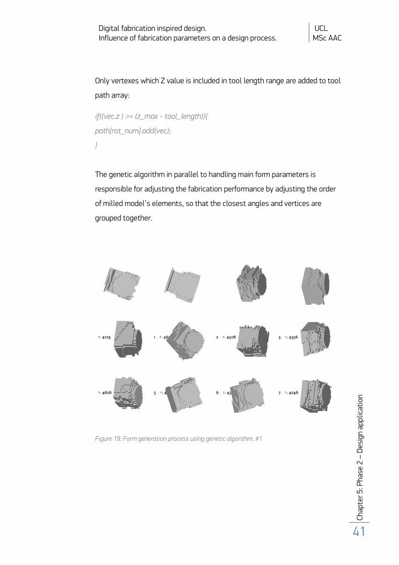
The genetic algorithm in parallel to handling main form parameters is
responsible for adjusting the fabrication performance by adjusting the order
of milled model’s elements, so that the closest angles and vertices are
grouped together.
Figure 19: Form generation process using genetic algorithm. #1

Digital fabrication inspired design. UCL Influence of fabrication parameters on a design process. MSc AAC
Cha
pter
5: P
hase
2 –
Des
ign
appl
icat
ion
42
Figure 20: Form generation process using genetic algorithm. #2
This stage of design results in a creation of form that fulfils the stated initial
requirements. The generated model is stored as a set of sorted tool path
vertices and workpiece rotational angles as the material removal fabrication
cycle is completed. Following procedure’s stage is based on the output form
from the first phase and its purpose is to treats and smooth out the given
rough model’s surface. Smoothing cycle is required for the form to become
even, so that the tool scratches can be minimised. So far in this design
procedure the 5-axis machine’s advantages were not put in use to the
maximum, because - although both angles were being adjusted in the same
time - the X, Y and Z axis played the most important role in model creation
and fabrication process. Smoothing cycle procedure is programmed with the
aim of linear axis movement minimisation in favour of the rotational axis
broader employment. Now only vertices positioned on the X axis can be
Digital fabrication inspired design. UCL Influence of fabrication parameters on a design process. MSc AAC
Cha
pter
5: P
hase
2 –
Des
ign
appl
icat
ion
43
milled and by implementing gradual change of angle B at fixed interval, which
as a result leads to lathe-type machine’s behaviour.
The last stage of the design process is the deployment of perforations on the
object’s surface. The fitness function calculates the number of drills in
different angles compared to the model’s surface normal vectors. The need
of such a design element was included in the initial requirement of providing
high level of light diffusion. This parameter is measured by the aggregated
value of difference between drilled perforations’ axis and model’s normal
vectors measured in the drill access point on the surface. Another factor
which influences the light diffusion is the perforations’ distribution. It is
aimed to achieve maximum even distribution of holes on all sides of the
model. Random angles’ configuration from the first generation evolves
gradually into more evenly sequenced angles, which results in both better
primary model processing and fabrication and in the same time in more
uniform distribution of perforations. All the perforations are of the same
diameter, as only one tool is used for fabrication of this design phase, which
was purely a design decision.
5.2.3 Potentials and Limitations
The creation and implementation of this type of a bespoke design tool in real
life applications requires precise knowledge of preferred fabrication method
with its detailed specifications in advance. Due to the constrained
adjustability of the program the design possibilities are limited to the ones
included in the predefined manufacturing method’s scope. Similar issues are
a subject of pre-rationalised approach to design to which this particular
implementation belongs. In design pre-rationalisation if the main focal point

Digital fabrication inspired design. UCL Influence of fabrication parameters on a design process. MSc AAC
Cha
pter
5: P
hase
2 –
Des
ign
appl
icat
ion
44
is the structural system only, the production process of it might still need
adjustments and fabrication post-rationalisation. The described procedure
overcomes this problem, because only fully fabricatable objects can be
created, on the other hand it restricts the potential design possibilities.
Expanding Whitehead’s classification of design approaches, another
subcategory of so-called fab-rationalisation is introduced based on
presented approach to design process.

Digital fabrication inspired design. UCL Influence of fabrication parameters on a design process. MSc AAC
Cha
pter
5: P
hase
2 –
Des
ign
appl
icat
ion
45
Phase2 - Results
5.3 The prototype
5.3.1 Output
On the current stage of the research the final procedure’s output was
tested in CNC Simulation software - particularly Predator Virtual CNC 2008
software was used. This decision was caused by limited access to the 5-axis
machine. The software proved to be crucial for the output file testing.
However, it is intended to build trial model on the purposed machine at an
early date. Broad machining options and parameters adjustability available in
Predator Virtual CNC software were corresponding with the predefined
machine’s options, and thus enabled the feasibility study model to be tested
only virtually at this stage. The physical prototypes of the previous research
phase fabricated on a 3-axis milling machine were also beforehand tested in
the CNC simulation software. It was required to test the default parameters
of layer thicknesses, tool diameters and generated tool path. Tool – model
collisions and surface smoothness outcome was also a test parameter. It
was proved that corresponding output was produced by both physical and
virtual models. Therefore it is assumed that the research second stage
design procedure’s end-product tested in simulation software will exhibit
similar correspondence with physically manufactured prototypes.
Testing designed objects in simulation software and fabricating physical
models is all the more imperative, as the model comprised of point cloud
appears to be very heavy in terms of computational demand and memory
use, therefore employing a standard visualisation tool for the presentation of
designs is highly inefficient in this particular case.

Digital fabrication inspired design. UCL Influence of fabrication parameters on a design process. MSc AAC
Cha
pter
5: P
hase
2 –
Des
ign
appl
icat
ion
46
5.3.2 Form generation
The form generation procedure however in this case based on a
simple geometric principle proved to have some underlying defects. The
depth buffer values are being measured in rigid grid intervals superimposed
onto a flat display window. Although, the units of equal size to depth buffer’s
interval are used for the point cloud’s deposition in space, the relative
location of both compared values do not correlate with each other, because
the view becomes distorted in angular projection. Even though an orthogonal
view is being evaluated the comparison between the depth buffer readings
and the model voxels coordinates is not accurate, which can in result lead to
incorrect geometry generation. Two plausible alternative solutions could be
applied in order to improve the accuracy of geometry analysis. The first one
requires implementation of an additional fitness function for the output
geometry evaluation. Nonetheless, as the output form is not predefined –
which is a primary discriminant of the designed procedure – the geometry
evaluation would require employment of an intelligent learning algorithm to
determine the correct and accidental shapes. Another more applicable
possible solution, which is yet to be tested, is a deployment of increased
resolution of depth buffer measurements with image sampling procedure,
which compared to the point cloud units would discharge from the shifting
between the two readings issue.

Digital fabrication inspired design. UCL Influence of fabrication parameters on a design process. MSc AAC
Cha
pter
5: P
hase
2 –
Des
ign
appl
icat
ion
47
Figure 21: Tool path trajectory of an output code for 5-axis milling machine.
5.3.3 Fabrication efficiency
Generated tool paths tested in simulation software present a good level of
accuracy for the material deposition phase. Subsequent material smoothing
stage still lucks precision and requires further development in order to
achieve results comparable with already available CAD/CAM conversion
software. It has been achieved to produce collision-free tool paths,
nevertheless the path-planning component of the procedure requires further
improvements. Although a similar path planning rule has been implemented
for both machines’ types, the algorithm proves to be less efficient and do not
meet the demand for the final models’ fabrication using a 5-axis milling
machine. While for the 3-axis machine the image in a zigzag manner, the
output path proves to be effective and free from redundant movements, this
is however not true for the 5-axis machine’s output code. Calculations of the
closest vertex results in complex often scattered paths that do not follow
axial directions.

Digital fabrication inspired design. UCL Influence of fabrication parameters on a design process. MSc AAC
Cha
pter
6: D
iscu
ssio
n
48
Discussion
6.1 Relevance to architectural profession
Digital revolution has influenced the architectural profession in various ways
- the introduction of digital fabrication processes enhanced the production of
custom made building elements so easily created by means of generative
procedures. Application of computational techniques in the design process
implies a tendency of adding increased complexity to forms, thus leading to a
shift in what we perceive as good architecture. Nowadays the relation
between designs and the way they were fabricated – also important
throughout history of architecture - is even more prominent. The construction
aspects of design are not only influencing the structural properties of
buildings or materials used, but also alter the design process as a whole.
Programming skills are becoming more and more in architectural profession,
as they give the designer a possibility of setting the relationships between
parameters of the design beforehand, which - if digital fabrication methods
are considered - permit these parameters to become an important factor or a
design core. Such a bottom-up approach impose on the designer a
responsibility of establishing how much the designer himself can intervene in
the process, parameters of which he can choose manually, which will be
predefined or customised by an algorithmic procedure. Using custom
developed program for form finding process also frees the designer from the
imposed in standard computer software aesthetic tendencies. Bottom-up
programming refers to the underlying relationship between building
elements, parameters or spatial configurations of a building, so important for
the forthcoming materialisation and attainability.
Digital fabrication inspired design. UCL Influence of fabrication parameters on a design process. MSc AAC
Cha
pter
6: D
iscu
ssio
n
49
The main focus of this thesis was to investigate the dependences and
possible influences of the two closely related elements of design process –
the form creation and fabrication stages – analysed in the light of digital
advances in both fields, namely the computer-aided design tools and digital
manufacturing. The assumption that the two still disconnected processes
could be linked together in a comprehensive design bespoke environment
was researched on the basis of two complementary studies. The first one
was designed to create a link between a designer-friendly parametric
language such as Processing and rapid prototyping techniques by creating a
user-oriented application for connecting the two. The interdependence of
both processes was the main subject of this study, therefore an
enhancement of a general purpose programming environment partially fulfils
the main objectives already and enables multiple users to take advantage of
it. The library however supports only 2,5 – axis machines, therefore the
attainable incorporation in architectural forms manufacturing is restrained to
panel-type elements or convex moulds. It can be also successfully utilised
for various non-architectural purposes and mere form exploration. On the
other side the G-Code export function, even though being very useful
presumably, does not influence the design process at any degree. The
assumption set out in the beginning of this research was the study of how
the digital fabrication characteristics can alter and enhance the design
process from the outset. Now then the library development stage did not
provide any valid answer to that problem, although its outcome provided an
indispensible starting point for creating the suitable scenario.
Diving into the subject it became clear that the mentioned programming
skills of architects should play the most important role in tying the entire
design-to-production process in such a way that the fabrication qualities
inform the designed form by themselves. Design framework was devised from

Digital fabrication inspired design. UCL Influence of fabrication parameters on a design process. MSc AAC
Cha
pter
6: D
iscu
ssio
n
50
5-axis CNC milling machine’s features. The generative procedure was
established with the aim of incorporating a wide variety of parameters, such
as for example: overall for of the object, its weight, light diffusion level and
most importantly suitability for the particular fabrication method. Usually
even if a bottom-up approach is taken while designing, the predefined form
tends to affect the programmable design dependencies, so that the output
will most likely fit within the designers’ established aesthetics, and therefore
the emergent forms are less probable to occur. Similar issue was
encountered during the lamp design process. Because the geometric was
very basic and formal delimitations quite restrictive, the generated form was
easily predictable. It seems to be more adequate to apply more general
formal rules for the procedure to demonstrate its full potential. Counter
arguing the above stated the predictable form was created in all probability
not due to procedure’s internal errors, but because it was enforced. The
constant back and forth parameters’ adjustment was in the first place
caused by the need of exploration of possible design solutions. Procedures,
which output did not fit the requisites, were discarded till the one that
fulfilled the creation of desired shape was found. Therefore taken bottom-up
approach was at some point stranded. Middle stage output forms are the
most correct effect of the selected path. This argumentation is referring to
the first stage of design development only, and can be a subject of further
discussion. The perforation creation stage does not fall in this concern. In
both stages the random factor was the one controlled by the genotype, but
what they differ in is the range of changes that can be executed by the
algorithm.
Digital fabrication inspired design. UCL Influence of fabrication parameters on a design process. MSc AAC
Cha
pter
6: D
iscu
ssio
n
51
6.2 Potential improvement strategy
Incorporated in the application the genetic algorithm was responsible for
handling many objectives in the same time. Although the most processor
absorbing procedure is the constant depth buffer values acquisition and
storing in resizable arrays. Collecting and storing countless vector
coordinates and continuous multi-objective fitness evaluation caused the
overall generation process to be inefficient and time-consuming.
The development of Graphics Processing Unit (GPU) also called the Visual
Processing Unit - which is a specialised graphics processor detached from
standard Computer Processing Unit - introduced major advances in computer
technology over the past decade (Boggan & Pressel, 2007). GPU became
responsible for performing complex three dimensional graphics rendering and
image rasterisation operations and thus discharged CPU from liability of
executing some highly demanding tasks. Lately programmable hardware
became widely exploited in manufacturing related disciplines, for instance
Roth et al. deployed an adaptive depth buffer method for multi-axial milling
machines as a solution to the CAD/CAM conversion problem and gained
substantial computation speed on calculating cutting forces (2003). In
evolutionary algorithms the most processor effort is dedicated to calculating
individual’s fitness function. Harding and Banzhaf present a solution for
significant increase in computational efficiency for calculating genetic
algorithm fitness function using Graphics Processing Unit (2007). By passing
on the major calculations from CPU to GPU it is possible to reduce the time
required for executing a single operation by hundreds of times.
Compute Unified Device Architecture (CUDA) developed by NVIDIA is a
parallel computing architecture that is capable of utilizing Graphics
Processing Units’ engine scope. Complex highly processor demanding

Digital fabrication inspired design. UCL Influence of fabrication parameters on a design process. MSc AAC
Cha
pter
6: D
iscu
ssio
n
52
calculations performed by applications developed with CUDA language
require significantly less time than those using Central Processing Unit based
languages only. The best performance can be achieved by using basic
programming languages like C, but wrappers are available for other
languages for example Java, C++ and MatLab. Therefore it is possible to
implement CUDA functions within Processing programming language, as it is
based on Java. It is though evident that high-level programming languages
could perform complex calculations with conjunction to GPU much quicker,
but advantages of using a simplified language dedicated for visual artists and
designers has a significant predomination of direct visual response and user-
friendly interface (NVIDIA Corporation, 2007).
6.3 Possible development and form generation procedures
Referring back to the issues with generative procedure principles,
here some plausible correct approaches are presented. Fabrication
parameters incorporation suggest that the form finding procedure should not
be based on geometric relationships of the desired object, but the machining
embedded principles should play a prominent role. The final shape should be
created by manipulating the machine’s activity by selecting different
combinations of angles and positions of the drill bit in relation to the material
block. This type of form finding would require more complex path planning for
the output forms fabrication. The virtual sculpted-model can be freely
created, but the physical model’s milling constraints are imperative.
Therefore it is not possible to simply set the form generation rules a priori,
but the implementation of evolutionary algorithms for evaluating the
correctness of each procedure. All that leads consequently to the conclusion
that genetic programming implementation for stated objectives would most

Digital fabrication inspired design. UCL Influence of fabrication parameters on a design process. MSc AAC
Cha
pter
6: D
iscu
ssio
n
53
aptly fulfil the stated goals of this thesis, as it would evaluate the form
generation procedures rather than the output of them.

Digital fabrication inspired design. UCL Influence of fabrication parameters on a design process. MSc AAC
Cha
pter
7: C
oncl
usio
n an
d fu
rthe
r w
ork
54
Conclusion
Research progress described in this thesis presents a custom solution to a
problem of linking two still disjoint processes of architectural design and
building fabrication stage. The aim was to create a multirole environment for
the designer to approach the form generation process from a different than
usual perspective. In was suggested that the digital fabrication objectives
could become a source of inspiration and a driving force of the design. In
order to explore the feasibility of such approach two design facilitating tools
were created. The first one was library for the Processing programming
language that enables direct G-Code file export of any three-dimensional
geometry from the design environment to 3-axis milling machine controllers.
At this stage factors such as path planning and optimisation of the output
code, computational efficiency and 3d geometry analysis were considered
and the results incorporated in final library, which is available for an open
source download. A more advanced step towards finding the relevant
solution was derived from accomplishment of the first step.
From the analytical study a more design oriented attitude was adopted in the
second phase of the research. Created design tool accomplished the primary
research objective of joining all the design stages in one comprehensive
application. Stages from form generation through optimisation to fabrication
output file preparation were executed within single bespoke program. The
aim was not only to join the processes together but redefine their
interdependence on the design stage. Owing to implementation of real-time
simulation of fabrication state at any stage which is a counterpart of visual
object generation the interdependence was enhanced. Only forms that meet
manufacturing constraints full are manageable, therefore no post-
rationalisation procedures are required for the object to be materialised.

Digital fabrication inspired design. UCL Influence of fabrication parameters on a design process. MSc AAC
:Cha
pter
7: C
oncl
usio
n an
d fu
rthe
r w
ork
55
Broadening the Whitehead’s classification of rationalisation approaches to
design into pre-, co- and post-rationalisation a new sub-category of fab-
rationalisation is introduced (2003). Similarily to pre-rationalisation the
parameters for physical fabrication are imposed on the design from the early
stages, however fab-rationalisation implies utilisation of these prerequisites
for enhancement of computer program’s creativity in forms’ generation and is
a crucial factor in design creation.
Both research stages proved to accomplish initial requirements in high
degree. Main research objective was successfully tested in a custom made
application and the link between design and production stages was re-
established. Some misfits emerged during the advancement of the research,
such as high processor load, maladjusted tool paths for the 5-axiss milling
machine fabrication and a need for generative procedure principles re-
evaluation as being the most important ones. The tool paths generation
algorithm, although requiring further corrections, produces codes ready for
use on CNC machines without need for alterations on this stage. It is the
efficiency and time-consumption of the fabrication process that needs to be
improved in the future. Also a few improvement methods were described for
possible implementation on successive stages of the research. As a result of
this thesis are being evaluated it becomes apparent that the developed
solutions for stated research question are only a tip of the iceberg and broad
further development following different paths is required in order to explore
potentials of this approach in depth.
Further work
Further development strategies exist for this research and include first of all
improvements of the generative procedure for form finding in the application.
Digital fabrication inspired design. UCL Influence of fabrication parameters on a design process. MSc AAC
:Cha
pter
7: C
oncl
usio
n an
d fu
rthe
r w
ork
56
It is necessary to create and analyse a number of case study examples in
order to experiment with the design technique in different scenarios. In the
next stage, which is also imperative for developing the design tool is the
fabrication of series of prototype models, which will make it possible to test
the tool trajectory in real life application as well as fabrication efficiency and
objects’ fitness for purpose.
Subsequently the improvements should be also made in the genetic
algorithm performance and a study over various ways of evaluating the
fitness function for multi-objective optimisation would be crucial for the
procedure further development. The more the genetic algorithm is efficient
the quicker and broader search of optimum solution can be performed. This
goal could be achieved by both restructuring of the procedure itself and
passing on the computationally heavy calculations to the Graphics
Processing Unit via incorporation of CUDA programming language functions
into the Processing language. GPU could also be tested for conducting the
depth buffer calculations, which all the more are originally being retrieved
from the graphic card hardware. As already mentioned in the discussion
chapter the role of genetic algorithm in the procedure could be taken over by
genetic programming procedure. Use of Genetic Programming indicate the
possibility of overcoming some inherit drawbacks of the present procedure.
Studied design approach, based on a particular digital fabrication
technique, could also be tested for eligibility for other digital manufacturing
methods, in particular big scale additive fabrication processes using
industrial robots.
Digital fabrication inspired design. UCL Influence of fabrication parameters on a design process. MSc AAC
:Cha
pter
8: R
efer
ence
s
57
Reference:
Afify, H.M.N. & Elghaffar, Z.A.A., 2007. Advanced digital manufacturing
techniques (CAM) in architecture. [Online] Menoufia University, Egypt
Available at: http://www.ascaad.org/conference/2007/006.PDF [Accessed 3
September 2009].
Attar, R. et al., 2009. Physics-based generative design. [Online] Available at:
http://www.autodeskresearch.com/papers/gendesign/CF09PhysicsGenDesign
.pdf [Accessed 29 August 2009].
Bhattacharya, P. & Gavrilova, M.L., 2007. Voronoi Diagram in Optimal Path
Planning. In 4th International Symposium on Voronoi Diagrams in Science and
Engineering. IEEE Computer Society Press, 2007. Los Alamitos.
Binnard, M., 1999. Design by Composition for Rapid Prototyping.
Massachusetts: Kluwer Academic Publishers.
Boggan, S. & Pressel, D.M., 2007. GPUs: An Emerging Platform for General-
Purpose Computation. [Online] Available at:
http://www.arl.army.mil/arlreports/2007/ARL-SR-154.pdf [Accessed 27
August 2009].
Bonwetsch, T., Gramazio, F. & Kohler, M., 2006. The informed Wall: applying
additive digital fabrication techniques on architecture. In Synthetic
Landscapes, Proceedings of the 25th Annual Conference of the Association
for Computer-Aided Design in Architecture. Louisville, 2006.
Botha, M. & Sass, L.D., 2006. The instant House, Design and digital
fabrication of housing for developing environments. [Online] Available at:
http://ddf.mit.edu/papers/09_botha_sass_caadria_2006.pdf [Accessed 27
August 2009].

Digital fabrication inspired design. UCL Influence of fabrication parameters on a design process. MSc AAC
:Cha
pter
8: R
efer
ence
s
58
Callicott, N., 2001. Computer-Aided Manufacture in Architecture, The Pursuit
of Novelty. Oxford: Architectural Press.
Carter, J.A., Tucker, T.M. & Kurfess, T.R., 2008. 3-Axis CNC Path Planning
Using Depth Buffer and Fragment Shader. [Online] CAD Solutions Available
at: http://www.cadanda.com/CAD_5_5__612-621.pdf [Accessed 27 August
2009].
Constructing Excellence, 2003. 3-D model makes complex steelwork simple.
[Online] Available at:
http://www.constructingexcellence.org.uk/pdf/case_studies/M4I222%20GLA
%20Case%20Study%20(DP%20219).pdf [Accessed 3 September 2009].
Corbusier, L., 1986; first edition, 1931. Towards a New Architecture.
thirteenth edition ed. New York: Dover Publications, Inc..
Dorigo, M. & Gambardella, L.M., 1997. Ant colonies for the traveling
salesman problem. Bio Systems, (43), pp.73-81.
Drenckhan, W. & Weaire, D., 2004. Some confluences of art and science in the
physics of foams. [Online] Symmetry: Art and Science, Tihany Congress
Available at:
http://www.maths.tcd.ie/~wiebke/PHYSICS/MY_PAPERS/ConfluencesOfArtAn
dScience.pdf [Accessed 3 September 2009].
Fischer, T., 2007. Rationalising bubble trusses for batch production. [Online]
Available at:
http://www.sciencedirect.com/science?_ob=ArticleURL&_udi=B6V20-
4HR75KR-
1&_user=10&_rdoc=1&_fmt=&_orig=search&_sort=d&_docanchor=&view
=c&_searchStrId=995334430&_rerunOrigin=google&_acct=C000050221&_v
Digital fabrication inspired design. UCL Influence of fabrication parameters on a design process. MSc AAC
:Cha
pter
8: R
efer
ence
s
59
ersion=1&_urlVersion=0&_userid=10&md5=80aefa41caccd3cfb92 [Accessed
29 August 1009].
Gramazio, F. & Kohler, M., 2006. Facade Gantenbein Winery, Fläsch
(Switzerland), 2006, Non-Standardised Brick Façade. [Online] ETH Zurich
Departement Architecture Available at:
http://www.dfab.arch.ethz.ch/web/e/forschung/52.html [Accessed 3
September 2009].
Gramazio, F. & Kohler, M., 2006. The Perforated Wall, ETH Zurich, 2006.
[Online] ETH Zurich Departement Architecture Available at:
http://www.dfab.arch.ethz.ch/web/e/lehre/83.html [Accessed 3 September
2009].
Gramazio, F. & Kohler, M., 2006. The Programmed Wall, ETH Zurich, 2006.
[Online] ETH Zurich Departement Architecture Available at:
http://www.dfab.arch.ethz.ch/web/e/lehre/81.html [Accessed 2 September
2009].
Gramazio, F. & Kohler, M., 2008. Manufactoring Material Effects Rethinking
Design and Making Architecture. In Kolarevic, B. & Klinger, K. Towards a
Digital Materiality. New York: Routledge. pp.103-18.
Harding, S. & Banzhaf, W., 2007. Fast genetic programming on GPUs. In
Ebner, M. et al., eds. Proceedings of the 10th European Conference on Genetic
Programming. Valencia, 2007. Springer.
Hasan, M., Gavrilova, M.L. & Ro, J.G., 2007. A Geometric Approach to
Clearance Based Path Optimisation. In ICCSA 2007, LNCS 4705. Berlin
Heidelberg, 2007. Springer-Verlag.
Digital fabrication inspired design. UCL Influence of fabrication parameters on a design process. MSc AAC
:Cha
pter
8: R
efer
ence
s
60
Ingenia, 2007. Box of bubbles. [Online] Available at:
http://www.ingenia.org.uk/ingenia/issues/issue33/Carfrae.pdf [Accessed 3
September 2009].
Johnson, D.S. & McGeoch, L.A., 1990. The Traveling Salesman Problem: A
Case Study in Local Optimization. In Goos G, H.J., ed. ICALP ’90: proceedings
of the 17th international colloquium on automata, languages and
programming. London, 1990. Springer-Verlag.
Joy, K.I., 2008. On-Line Computer Graphics Notes: The depth-buffer visible
surface algorithm. [Online] Visualization and Graphics Research Group,
Department of Computer Science University of California, Davis Available at:
http://www.idav.ucdavis.edu/education/GraphicsNotes/Z-Buffer-
Algorithm.pdf [Accessed 1 September 2009].
Klinger, K.R., 2001. Making Digital Architecture: Historical, Formal, and
Structural Implications of Computer Controlled Fabrication and Expressive
Form. In Education in ComputerAided Architectural Design in Europe
(eCAADe) Conference 2001:Architectural Information Management. Helsinki,
2001.
Kolarevic, B., 2006. Digital Fabrication: From digital to material. [Online]
Available at: http://www.iit.edu/~mcleish/arch497_DDF/branko_kolarevic.pdf
[Accessed 27 August 2009].
Makhanov, S., 2008. Mathematical Methods for Optimization of Cutting
Operations of 5-Axis Milling Machines. [Online] School of Information and
Computer Technology, Rangsit, Thailand Available at:
http://atcm.mathandtech.org/EP2008/papers_full/2412008_14580.pdf
[Accessed 3 September 2009].
Digital fabrication inspired design. UCL Influence of fabrication parameters on a design process. MSc AAC
:Cha
pter
8: R
efer
ence
s
61
McKenney, D., 1998. Model Quality: The Key to CAD/CAM/CAE
Interoperability. In MSC Americas Users' Conference. Universal City, CA, 1998.
MSC Software.
Montemanni, R., Barta, J., Mastrolilli, M. & Gambard, L.M., 2007. Heuristic
algorithms for the robust traveling salesman problem with interval data.
Transportation Science, (41(3)), pp.366-81.
NVIDIA Corporation, 2007. NVIDIA CUDA Compute Unified Device
Architecture. [Online] NVIDIA Corporation Available at:
http://developer.download.nvidia.com/compute/cuda/1_0/NVIDIA_CUDA_Pro
gramming_Guide_1.0.pdf [Accessed 1 September 1009].
Oberholzer, M., 2006. Greater London Authority. [Online] Available at:
http://www.owlnet.rice.edu/~arch214/gla_foster.pdf [Accessed 3 Seotember
2009].
Roth, D., Ismail, F. & Bedi, S., 2003. Mechanistic modelling of the milling
process using an adaptive depth buffer. [Online]
(http://www.sciencedirect.com/science?_ob=ArticleURL&_udi=B6TYR-
488VSB9-
1&_user=10&_rdoc=1&_fmt=&_orig=search&_sort=d&_docanchor=&view
=c&_searchStrId=997857252&_rerunOrigin=google&_acct=C000050221&_v
ersion=1&_urlVersion=0&_userid=10&md5=be2a6bee602c9740a29)
[Accessed 29 August 2009].
Saiko, D., 2005. Traveling Salesman Problem, Java Genetic Algorithm
Solution. [Online] Available at:
http://www.google.pl/url?sa=t&source=web&ct=res&cd=8&url=http%3A%2
F%2Fjava-traveling-salesman.googlecode.com%2Ffiles%2Ftsp-
documentation.pdf&ei=kX6oSpfBONefjAeGsejYBw&rct=j&q=travelling+sales

Digital fabrication inspired design. UCL Influence of fabrication parameters on a design process. MSc AAC
:Cha
pter
8: R
efer
ence
s
62
man+problem+filetype%3Apdf&usg=AFQjCNGSBSSV6HxB336WetHvydeytJl
bB [Accessed 3 September 2009].
Seely, J.C., 2004. Digital fabrication in the architectural design process.
[Online] Massachusetts: Massachusetts Institute of Technology Available at:
http://dspace.mit.edu/bitstream/handle/1721.1/27030/56780968.pdf?sequenc
e=1 [Accessed 27 August 2009].
Whitehead, H., 2003. Laws of Form. In Kolarevic, B. Architecture in the Digital
Age Design and Manufacturing. New York and London: Spon Press. pp.82-
100.

Digital fabrication inspired design. UCL Influence of fabrication parameters on a design process. MSc AAC
Cha
pter
9: A
ppen
dice
s
63
Appendix 1
G-Code and M-code basic functions according to
http://linuxcnc.org/handbook/gcode/g-code.html:
G0 rapid positioning
G1 linear interpolation
G2 circular/helical interpolation (clockwise)
G3 circular/helical interpolation (c-clockwise)
G4 dwell
G10 coordinate system origin setting
G17 xy plane selection
G18 xz plane selection
G19 yz plane selection
G20 inch system selection
G21 millimetre system selection
G40 cancel cutter diameter compensation
G41 start cutter diameter compensation left
G42 start cutter diameter compensation right
G43 tool length offset (plus)
G49 cancel tool length offset
G53 motion in machine coordinate system
G54 use preset work coordinate system 1
G55 use preset work coordinate system 2
G56 use preset work coordinate system 3
G57 use preset work coordinate system 4
G58 use preset work coordinate system 5
G59 use preset work coordinate system 6
G59.1 use preset work coordinate system 7
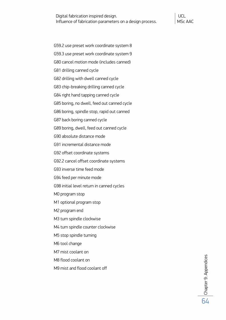
Digital fabrication inspired design. UCL Influence of fabrication parameters on a design process. MSc AAC
Cha
pter
9: A
ppen
dice
s
64
G59.2 use preset work coordinate system 8
G59.3 use preset work coordinate system 9
G80 cancel motion mode (includes canned)
G81 drilling canned cycle
G82 drilling with dwell canned cycle
G83 chip-breaking drilling canned cycle
G84 right hand tapping canned cycle
G85 boring, no dwell, feed out canned cycle
G86 boring, spindle stop, rapid out canned
G87 back boring canned cycle
G89 boring, dwell, feed out canned cycle
G90 absolute distance mode
G91 incremental distance mode
G92 offset coordinate systems
G92.2 cancel offset coordinate systems
G93 inverse time feed mode
G94 feed per minute mode
G98 initial level return in canned cycles
M0 program stop
M1 optional program stop
M2 program end
M3 turn spindle clockwise
M4 turn spindle counter clockwise
M5 stop spindle turning
M6 tool change
M7 mist coolant on
M8 flood coolant on
M9 mist and flood coolant off

Digital fabrication inspired design. UCL Influence of fabrication parameters on a design process. MSc AAC
Cha
pter
9: A
ppen
dice
s
65
M26 enable automatic b-axis clamping
M27 disable automatic b-axis clamping
M30 program end, pallet shuttle, and reset
M48 enable speed and feed overrides
M49 disable speed and feed overrides
M60 pallet shuttle and program stop
Appendix 2
G-Code sample program for cutting letter M:
N10 T2 M6 -
N20 G54 G90 S1500 M3
N30 G00 X10 Y10 Z10
N40 G01 Z-4
N50 X90
N60 X40 Y40
N70 X90 Y70
N80 X10
N90 G00 Z10
N80 G00 X10 Y0
N90 M30
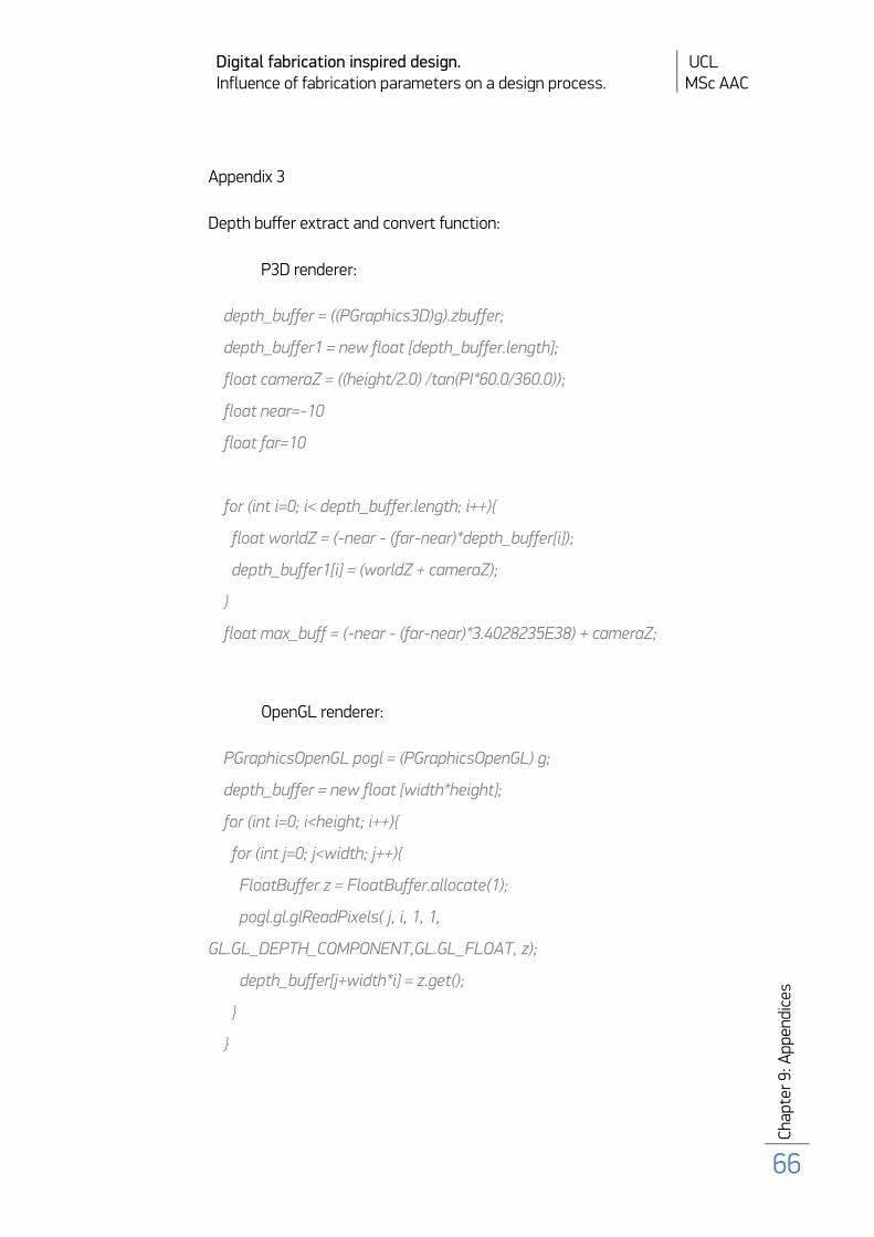
Digital fabrication inspired design. UCL Influence of fabrication parameters on a design process. MSc AAC
Cha
pter
9: A
ppen
dice
s
66
Appendix 3
Depth buffer extract and convert function:
P3D renderer:
depth_buffer = ((PGraphics3D)g).zbuffer;
depth_buffer1 = new float [depth_buffer.length];
float cameraZ = ((height/2.0) /tan(PI*60.0/360.0));
float near=-10
float far=10
for (int i=0; i< depth_buffer.length; i++){
float worldZ = (-near - (far-near)*depth_buffer[i]);
depth_buffer1[i] = (worldZ + cameraZ);
}
float max_buff = (-near - (far-near)*3.4028235E38) + cameraZ;
OpenGL renderer:
PGraphicsOpenGL pogl = (PGraphicsOpenGL) g;
depth_buffer = new float [width*height];
for (int i=0; i<height; i++){
for (int j=0; j<width; j++){
FloatBuffer z = FloatBuffer.allocate(1);
pogl.gl.glReadPixels( j, i, 1, 1,
GL.GL_DEPTH_COMPONENT,GL.GL_FLOAT, z);
depth_buffer[j+width*i] = z.get();
}
}

Digital fabrication inspired design. UCL Influence of fabrication parameters on a design process. MSc AAC
Cha
pter
9: A
ppen
dice
s
67
depth_buffer1 = new float [depth_buffer.length];
float cameraZ = ((height/2.0) /tan(PI*60.0/360.0));
float near = cameraZ/10;
float far = cameraZ*10;
for (int i=0; i< depth_buffer.length; i++){
float worldZ = (-near - (far-near)*depth_buffer[i]);
depth_buffer1[i] = (worldZ + cameraZ);
}
float max_buff = (-near - far-near) + cameraZ;

Digital fabrication inspired design. UCL Influence of fabrication parameters on a design process. MSc AAC
Cha
pter
9: A
ppen
dice
s
68
Appendix 4
Sample code of a Processing sketch using PGCode3D library for exporting a
simple box primitive for digital fabrication.
import PGCode3D.*;
G_code_export gc;
void setup()
{
size(100, 100, P3D); // both P3D and OpenGL are supported
gc = new G_code_export (this,6,3,”cnc_code_nowe”,200);
//T01 – 6mm, T02 – 3mm, material thickness – 20 cm
background(255);
stroke(255);
fill(0);
}
void draw()
{
ortho();
pushMatrix();
rotateY(PI/6);
rotateX(PI/6);
translate(width/2, height/2,-height/2);
box(30);
popMatrix();
gc.print_data(); //println the model data

Digital fabrication inspired design. UCL Influence of fabrication parameters on a design process. MSc AAC
Cha
pter
9: A
ppen
dice
s
69
if(keyPressed){
gc.change_settings(5,3000,150,3);
// 5-offset above material, 3000 – spindle speed, 150 – feed rate, 3 – layer
thickness
gc.optimise_path(1000); //optimise throughout 1000 generation
gc.export(); //will println “generated” when the view analysis is completed
and “file written” for the complete export
exit();
}
}
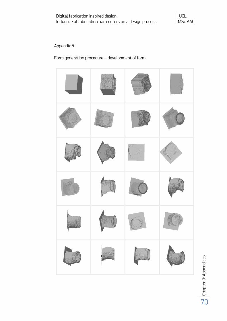
Digital fabrication inspired design. UCL Influence of fabrication parameters on a design process. MSc AAC
Cha
pter
9: A
ppen
dice
s
70
Appendix 5
Form generation procedure – development of form.
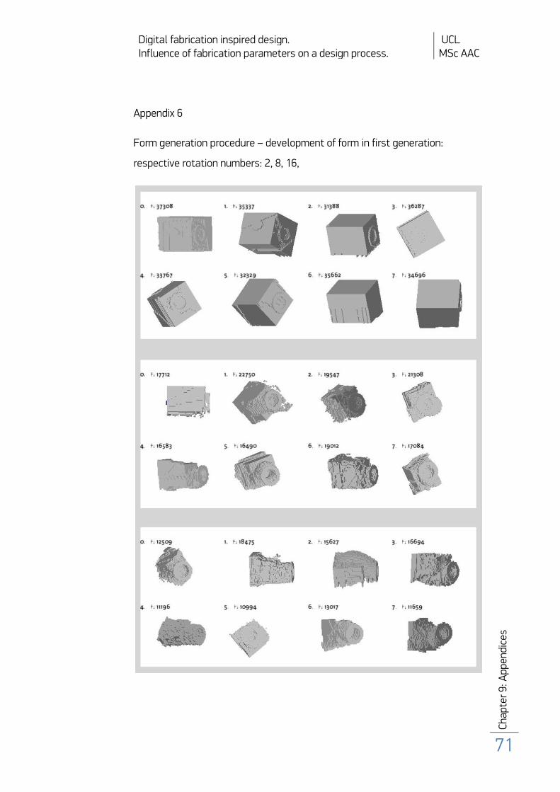
Digital fabrication inspired design. UCL Influence of fabrication parameters on a design process. MSc AAC
Cha
pter
9: A
ppen
dice
s
71
Appendix 6
Form generation procedure – development of form in first generation:
respective rotation numbers: 2, 8, 16,