digital instrument display for cars siti...
TRANSCRIPT

DIGITAL INSTRUMENT DISPLAY FOR CARS
SITI MARIAM BINTI HUSSAIN
This Report Is Submitted In Partial Fulfillment Of Requirements For The Bachelor
Degree Of Electronic Engineering with Honours (Industrial Electronic)
Fakulti Kejuruteraan Elektronik dan Kejuruteraan Komputer
Universiti Teknikal Malaysia Melaka
May 2007

ii
UNIVERSITI TEKNIKAL MALAYSIA MELAKA
FAKULTI KEJURUTERAAN ELEKTRONIK DAN KEJURUTERAAN KOMPUTER
BORANG PENGESAHAN STATUS LAPORAN PROJEK SARJANA MUDA II
Tajuk projek : Digital Instrument Display For Cars
Sesi pengajian : 2006/2007
Saya SITI MARIAM BINTI HUSSAIN
(HURUF BESAR)
Mengaku membenarkan laporan Sarjana muda ini disimpan di perpustakaan dengan syarat-syarat seperti
berikut:
2. perpustakaan dibenarkan membuat salinan untuk tujuan pengajian sahaja
3. perpustakaan dibenarkan membuat salinan laporan sebagai pertukaran antara institusi pengajian tinggi.
4. Sila tandakan ( √ )
( Mengandungi maklumat yang berdarjah keselamatan atau
SULIT* kepentingan Malaysia seperti yang termaktub di dalam AKTA
RAHSIA RASMI 1972)
( Mengandungi akta maklumat TERHAD yang telah ditentukan oleh
TERHAD* organisasi/badan di mana penyelidikan di jalankan.
TIDAK TERHAD Disahkan oleh:
___________________ __________________________ (TANDATANGAN PENULIS) (COP DAN TANDATANGAN PENYELIA) Alamat tetap: D/A Kedai Mustafa, Kg. Kemayang,
Tawang, 16020 Bachok, Kelantan.
Tarikh: 27 April 2007 Tarikh: 27 April 2007 *CATATAN: Jika laporan ini SULIT atau TERHAD, sila lampirkan surat daripada pihak berkuasa/organisasi
berkenaan dengan menyatakan sekali tempoh laporan ini perlu dikelaskan sebagai SULIT dan TERHAD.
iii
DECLARATION
“I admit that this is done by myself except the discussion and extracts taken from other
sources that I explained each in detail.”
Signature :
Writer Name : Siti Mariam Binti Hussain
Date : 27 April 2007
iv
SUPERVISOR APPROVAL
“I admit that I have read this literature work through my observation which has fulfilled
the scope and quality in order to be qualified for the conferment of Bachelor Degree in
Electronic Engineering with Honours (Industrial Electronic)”
Signature :
Supervisor Name : Prof. Abdul Hamid bin Hamidon
Date : 27 April 2007
v
DEDICATION
To my parents, family members, friends and all which involved;
My all times beloved.
vi
ACKNOWLEDGEMENTS
Alhamdulillah, Finally, I am able to complete the final year project and the thesis
as well within the allocated time. First of all, I would like to express my greatest
gratitude and sincere thanks to my supervisor, Prof. Abdul Hamid bin Hamidon, for his
valuable advice and assistance in the supervision and consultation of this Final Year
Project. In fact, he gave me guidance when obstacles arise throughout this period of
time. Once again, I thank for his tolerance and endeavors. I also want to take this
opportunity to express my appreciation to some organizations and individuals who have
kindly contributed to the successfully completion of my final year project in UTeM.
With the cooperation and contributions from all parties, the objectives of the project,
soft-skills, knowledge and experiences were gained accordingly. Thanks a lot to all
FKEKK lecturers because willing to give an opinion and also give me guide for realize
this project. Everything idea you all give for me is very constructive and help me to
solve the technical problem during I do this project. Furthermore, I would like to extend
my sincere acknowledgement to my parents and family members who have been very
supportive throughout the project. Their understanding and support in term of moral and
financial were entirely significance towards the project completion. Last but not list, my
appreciation goes to my fellow colleagues in UTeM, especially for those who came from
FKEKK. Their willingness to help, opinions and suggetions on some matters, advices
and technical knowledge are simply precious while doing upon completion of my final
year project.
vii
ABSTRACT
The Digital Instrument Display for Cars is based on a PIC microcontroller. This
project converts the analogue instruments in cars to a digital display. It is suitable for use
with fuel gauges, oil pressure gauges or temperature gauges. It is designed to operate
with any sensor or sender unit which varies its resistance or voltage signal output and
display the result on a 3-digit LED readout. Basically, it is ideal for use with sender units
that have relatively slow changing values. In operation, the unit can be calibrated so that
the display will show any value in the range from -99 through to 999. The decimal point
can also be placed in one of two positions, so that the values can be from -.99 to 99.9. In
addition, the unit can be calibrated to display metric or imperial units. The Digital
Instrument Display is calibrated at two values and the instrument calculates the
remaining values from these in a linear fashion. For example, if the unit is to be used as
a fuel gauge, it is best calibrated when the fuel tank is full and then calibrated when the
tank is close to empty. The display will then subsequently be able to show the remaining
fuel in the tank over the complete range from full to empty.

viii
ABSTRAK
Alat Paparan Digital Untuk Kereta ini berasaskan pada pengawal mikro PIC.
Projek ini menukar alatan analog dalam kereta kepada paparan digital. Ianya sesuai
digunakan dengan pengukur minyak, pengukur tekanan minyak atau pun pengukur suhu.
Ianya direka untuk beroperasi dengan sebarang sensor atau unit penghantar yang berbeza
kerintangannya atau isyarat keluaran voltan dan hasilnya dipaparkan pada tiga digit
paparan 7 ruas. Pada asasnya, ianya sesuai digunakan dengan unit penghantar yang
mempunyai nilai perubahan relatif yang perlahan. Pada operasinya, unit boleh
dikalibrasi untuk membolehkan paparan memaparkan sebarang nilai dalam linkungan -
99 sehingga 999. Titik perpuluhan juga boleh diletakkan pada satu atau dua tempat,
menjadikan nilai dari -.99 sehingga 99.9. Tambahan pula, unit boleh dikalibrasi untuk
paparan metric atau unit imperial. Alatan Paparan Digital dikalibrasi pada dua nilai dan
alat ini mengira nilai baki dalam bentuk linear. Contohnya, jika unit digunakan sebagai
pengukur minyak, kalibrasi elok dilakukan semasa tangki minyak penuh dan
menghampiri kosong. Paparan berikutnya akan memaparkan baki minyak dalam tangki
dalam linkungan dari penuh kepada kosong.
ix
TABLE OF CONTENTS
CHAPTER DESCRIPTION PAGE
PROJECT TITLE
REPORT STATUS APPROVAL FORM
DECLARATION iii
SUPERVISOR APPROVAL iv
DEDICATION v
ACKNOWLEDGEMENTS vi
ABSTRACT vii
ABSTRAK viii
TABLE OF CONTENTS ix
LIST OF TABLES xii
LIST OF FIGURES xiii
LIST OF ABBREVIATIONS xv
LIST OF APPENDIXS xvii
I INTRODUCTION
1.1 Introduction Of The Project 1
1.2 Project Objective 2
1.3 Problem Statement 2
1.4 Scope Of Works 3
1.5 Method Of Project 4
1.6 Thesis Outline 5
x
II LITERATURE REVIEW
2.1 Analog-to-digital Converter 6
2.2 Successive Approximation ADC 7
2.3 Practical Considerations Of ADC Circuits 9
2.4 Introduction Of PIC16F84 11
2.5 Pin Description 13
2.6 Seven-Segment Display (Multiplexing) 14
-programming example
2.7 PIC Programmer 21
2..7.1 Flash PIC USB Programmer Electronic Kit 21
2.7.2 Programmer For A Broad Range PC Processors 22
III PROJECT METHODOLOGY
3.1 Project Overview 23
3.2 Project Plan And requirement 24
3.2.1 Components Selection 25
3.2.2 Construct And Test 25
3.3 Methodology Analysis 26
3.3.1 PIC Microcontroller 26
3.3.1.1 PIC 16F84A Main Features 27
3.3.2 Source Code 30
3.3.3 7-segment LED Display 30
3.3.4 Truth Table of 7-Segment display 32
(Common-Anode)
3.4 Project Design And Implementation 33
3.4.1 Hardware 33
3.4.1.1 Component List 35
3.4.1.2 Circuit Details 38
3.4.1.3 Alarm Output 38
xi
3.4.1.4 Presentation 39
3.4.1.5 Different Modes 39
3.4.1.6 A-D converter 41
3.4.1.7 LED Displays 43
3.4.1.8 Display Dimming 44
3.4.1.9 Mode Switches 45
3.4.1.10 Power 45
3.4.1.11 PCB Design 46
3.4.1.12 Component Placement And 48
Soldering Process
3.4.2 Software 50
3.4.2.1 Workflow Of Program The PIC 51
3.4.2.2 Flow Chart Of Digital Instrument Display 52
IV RESULT AND ANALYSIS
4.1 Circuit Test 53
4.1.1 Circuit Testing Analysis 56
4.2 Programming Testing 56
V DISCUSSION AND CONCLUSION
5.1 Discussion 61
5.2 Project Improvement And Suggestions 62
5.3 Conclusion 62
REFERENCES 63
APPENDIX 64
xii
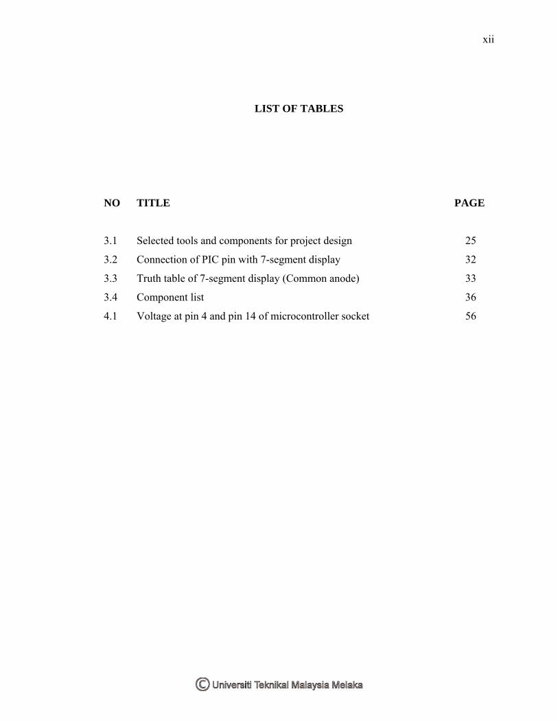
LIST OF TABLES
NO TITLE PAGE
3.1 Selected tools and components for project design 25
3.2 Connection of PIC pin with 7-segment display 32
3.3 Truth table of 7-segment display (Common anode) 33
3.4 Component list 36
4.1 Voltage at pin 4 and pin 14 of microcontroller socket 56

xiii
LIST OF FIGURES
NO TITLE PAGE
1.1 Diagram of process 3
1.2 Flow chart of brief methodology 4
2.1 Block Diagram of ADC 7
2.2 Successive approximation 8
2.3 Successive approximation ADC 9
2.4 Example of ADC used 10
2.5 Harvard vs. von Neuman block architecture 12
2.6 PIC16F84 pins diagram 13
2.7 7-segment display 14
2.8 Connecting a microcontroller to 7-segment display in multiplex mode 16
2.9 Flash PIC USB Programmer Electronic Kit 21
2.10 Programmer for a broad range PC processors 22
3.1 Block diagram for project major elements 23
3.2 Block diagram for project methodology 24
3.3 Pin diagrams for PIC16F84A 27
3.4 PIC16F84A block diagram 28
3.5 7-segment dimensions 31
3.6 Internal circuit diagram of 7-segment display 31
3.7 Segment of seven-segment display 32
3.8 Block diagram of the project 34
3.9 Digital instrument display circuit 37
3.10 PCB design for display board 46
xiv
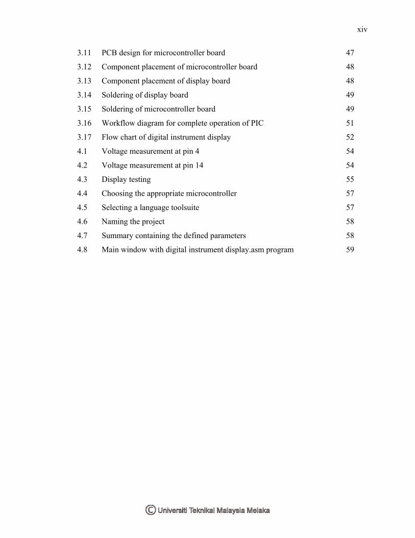
3.11 PCB design for microcontroller board 47
3.12 Component placement of microcontroller board 48
3.13 Component placement of display board 48
3.14 Soldering of display board 49
3.15 Soldering of microcontroller board 49
3.16 Workflow diagram for complete operation of PIC 51
3.17 Flow chart of digital instrument display 52
4.1 Voltage measurement at pin 4 54
4.2 Voltage measurement at pin 14 54
4.3 Display testing 55
4.4 Choosing the appropriate microcontroller 57
4.5 Selecting a language toolsuite 57
4.6 Naming the project 58
4.7 Summary containing the defined parameters 58
4.8 Main window with digital instrument display.asm program 59

xv
LIST OF ABBREVIATIONS
PIC - Peripheral Interface Controller
PCB - Printed Circuit Board
LCD - Liquid Crystal Display
LED - Light Emitting Diode
ADC - Analog To Digital Converter
PWM - Pulse Width Modulation
BCD - Binary Code Decimal
SAR - Successive-Approximation Register
RAM - Random Access Memory
CPU - Central Processing Unit
SMD - Surface Mount Devices
DIP - Dual In Package
Dp - Decimal Point
POV - Persistance Of Vision
PC - Personal Computer
RISC - Reduce Instruction Set Computer
ICSP - In-Circuit Serial Programming
POR - Power-on Reset
PWRT - Power-up Timer
OST - Oscillator Start-up Timer
WDT - Watchdog Timer
ASM - Assembly Language
DC - Direct Current
REG - Regulator
xvi
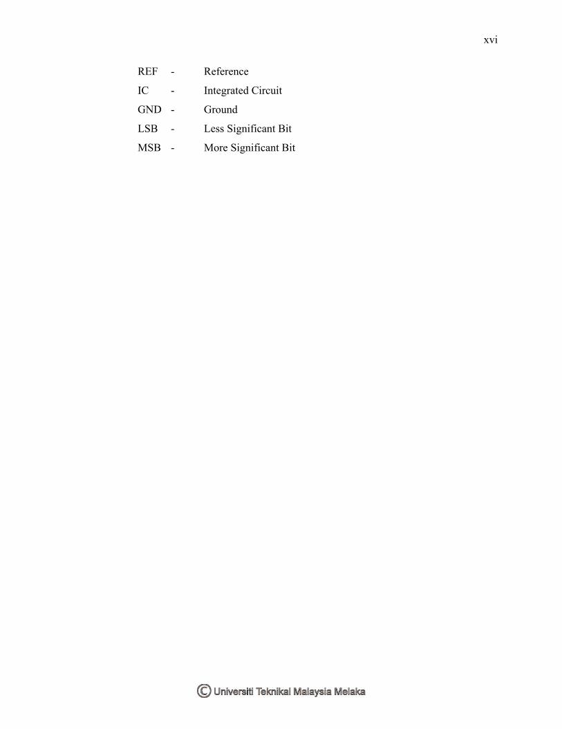
REF - Reference
IC - Integrated Circuit
GND - Ground
LSB - Less Significant Bit
MSB - More Significant Bit
xvii
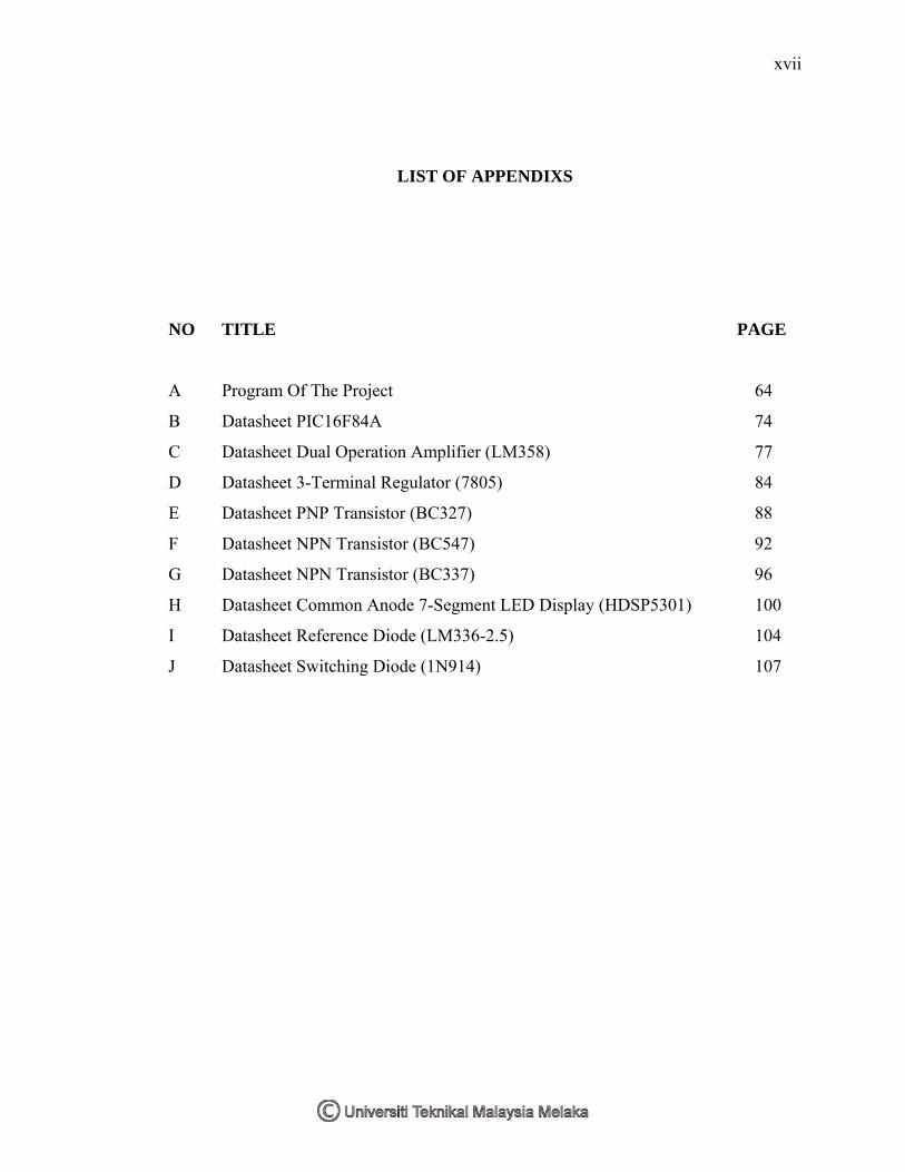
LIST OF APPENDIXS
NO TITLE PAGE
A Program Of The Project 64
B Datasheet PIC16F84A 74
C Datasheet Dual Operation Amplifier (LM358) 77
D Datasheet 3-Terminal Regulator (7805) 84
E Datasheet PNP Transistor (BC327) 88
F Datasheet NPN Transistor (BC547) 92
G Datasheet NPN Transistor (BC337) 96
H Datasheet Common Anode 7-Segment LED Display (HDSP5301) 100
I Datasheet Reference Diode (LM336-2.5) 104
J Datasheet Switching Diode (1N914) 107
CHAPTER I
INTRODUCTION
1.1 Introduction Of The Project
Most cars have analogue readouts for displaying fuel level and engine
temperature. The oil pressure is either shown on an analogue gauge or more commonly,
there is no gauge but just an “idiot” warning light. There is nothing wrong with analogue
gauges. Some drivers would rather have these outputs displayed in digital format. That is
where this Digital Instrument Display comes in.
The Digital Instrument Display for Cars is based on a PIC microcontroller. This
project converts the analogue instruments in cars to a digital display. It is suitable for use
with fuel gauges, oil pressure gauges or temperature gauges in cars. It is designed to
operate with any sensor or sender unit which varies its resistance or voltage signal
output due to changes in input. The result is displayed on 3-digit LED readout.
Basically, it is ideal for use with sender units that have relatively slow changing values.
In operation, the unit can be calibrated so that the display will show any value in the
range from -99 through to 999. The decimal point can also be placed in one of two
positions, so that the values can be from -.99 to 99.9. In addition, the unit can be
calibrated to display metric or imperial units. Fuel and temperature gauges do not
usually show precise values. Instead, they give a general indication of how things are

2
going. As an example, remaining fuel level somewhere between full and half-empty or
temperature midway between hot and cold. By contrast, it can calibrate this digital
display unit to show the actual values. The Digital Instrument Display is calibrated at
two values and the instrument calculates the remaining values from these in a linear
fashion. For example, if the unit is to be used as a fuel gauge, it is best calibrated when
the fuel tank is full and then calibrated when the tank is close to empty. The display will
then subsequently be able to show the remaining fuel in the tank over the complete range
from full to empty.
1.2 Project Objective
To design the Digital Instrument Display circuit that can:
Convert the analogue display in cars to a digital display.
In order to ensure that the project objectives are met:
• To be able to program Peripheral Interface Controller (PIC) microcontroller:
- As an analog to digital converter
- To display the digital value by BCD 7-segment.
1.3 Problem Statement
Most cars have analogue readouts for displaying fuel level and engine
temperature. Similarly, the oil pressure is either shown on an analogue gauge or more
commonly, there is no gauge and just an “idiot” warning light instead. Of course, there
is nothing wrong with analogue gauges, it is just that some drivers would rather have
these outputs displayed in digital format. With a digital display, the driver can know
more details about the fuel level and engine temperature.

3
1.4 Scope Of Works
Input sensing circuit Output
Part 1 Part 2
Figure 1.1 : Diagram of process
This project is divided into two parts, the first part is the controller circuit using
PIC (Microchip Peripheral Interface Controller). The second part is the digital
instrument display circuit. The operation of the product will be controlled by a PIC. For
the PIC, program will be written using assembly language and burnt. The digital
instrument display circuit will be then be constructed. Testing and calibration on real
hardware will be carried out to ensure it is functionally correct.
Analog signal PIC Microcontroller Digital Display
4
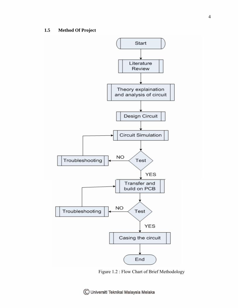
1.5 Method Of Project
Figure 1.2 : Flow Chart of Brief Methodology
5
1.6 Thesis Outline
This report is divided into several chapters. They are
I. Introduction
II. Literature Review
III. Project Methodology
IV. Result and Discussion
V. Conclusion and Suggestion
This thesis represent by five chapters. Chapter I will focus on brief introduction
of the project carried. The important overview or description including the problem
statement, project objectives and project scopes are well emphasized in this part.
Chapter II will be based on the literature review of the project. It is mainly
focused on the analog to digital converter, PIC16F84A and about seven-segment display
(multiplexing). It also defined the details including PIC programmer.
Chapter III will explain on the concepts, theories and principle used in order to
complete the project. This part consists of the methodology and also the information on
research, experiment and simulation carried during the project development.
Chapter IV mainly focused on the result and analysis done using the device. All
testing and verification result are attached with the aid of figure, table and statistic
related to the project.
Chapter V is a complimentary of previous four chapters. It describes on the
overall project, discussion and suggestion for the project. All matters arise including the
problems and unachieved objectives will be described clearly in this part.
CHAPTER II
LITERATURE REVIEW
2.1 Analog-to-digital Converter
An analog-to-digital converter (abbreviated ADC, A/D or A to D) is an
electronic circuit that converts continuous signals to discrete digital numbers. Typically,
an ADC is an electronic device that converts an input analog voltage to a digital number.
The digital output may be using different coding schemes, such as binary and two's
complement binary. However, some non-electronic or only partially electronic devices,
such as shaft encoders, can also be considered as ADCs.
An ADC inputs an analog electrical signal such as voltage or current and outputs
a binary number. In block diagram form, it can be represented as such:

7
Figure 2.1 : Block Diagram of ADC
2.2 Successive Approximation ADC
The successive-approximation converter is one of the most widely used types of
ADC. One method of addressing the digital ramp ADC's shortcomings is the so-called
successive-approximation ADC. The only change in this design is a very special counter
circuit known as a successive-approximation register. Instead of counting up in binary
sequence, this register counts by trying all values of bits starting with the most-
significant bit and finishing at the least-significant bit. Throughout the count process, the
register monitors the comparator's output to see if the binary count is less than or greater
than the analog signal input, adjusting the bit values accordingly. The way the register
counts is identical to the "trial-and-fit" method of decimal-to-binary conversion,
whereby different values of bits are tried from MSB to LSB to get a binary number that
equals the original decimal number. The advantage to this counting strategy is much
faster results.
Without showing the inner workings of the successive-approximation register
(SAR), the circuit looks like this: