digital land mobile systems for dispatch traffic - tt. itu-r m.2014-1 1 report itu-r m.2014-1...
TRANSCRIPT

Rep. ITU-R M.2014-1 1
REPORT ITU-R M.2014-1
Digital land mobile systems for dispatch traffic (Question ITU-R 37/8)
(1998-2006)
Scope
Demand in the land mobile service is on the increase due to annual growth as well as to new data-based service requirements. This has led to the development of more spectrally efficient technologies utilizing digital modulation and in many cases trunking. These technologies are being introduced in systems worldwide to accommodate this demand.
This Report provides the technical and operational characteristics for spectrum efficient digital dispatch systems and also provides details of systems being introduced throughout the world.
This Report is a compilation of descriptions of systems, which implies that neither technical nor intellectual property rights evaluations were performed in its preparation. Further details are available in the ITU Publication – Land Mobile Handbook (including Wireless Access) – Volume 3: Dispatch and Advanced Messaging Systems, and are not included here.
1 General objectives The general objectives of a spectrum efficient digital land mobile system, for dispatch in either private or public systems, are to provide: – systems that offer a higher spectrum efficiency, thereby accommodating more users within
limited spectrum resources than analogue systems; – a higher average level of voice quality over the network and enciphered speech for privacy; – users with a wide range of services and facilities, both voice and non-voice, that are
compatible with those offered by the public fixed networks (public switched telephone network (PSTN), public data network (PDN), integrated services digital network (ISDN), etc.);
– users with a variety of applications to satisfy their requirements, ranging from handheld stations to vehicle mounted stations, with voice and data interfaces;
– mobile and infrastructure equipment which use state of the art technology to provide savings in weight, power consumption and cost.
2 Service types The basic services offered by a digital dispatch traffic system can be divided into three types: – teleservices; – bearer services; and – supplementary services.
2 Rep. ITU-R M.2014-1
2.1 Teleservices Teleservices provide the user with full capability, including terminal equipment functions, to communicate with other users. Both lower layer (open systems interconnection (OSI) layers 1 through 3) and higher layers (OSI layers 4 to 7) functionality typify these services.
Typical teleservices should include: – a trunked and non-trunked capability to permit direct mobile-to-mobile and group speech
call facilities with user options to permit selective and secure calling; – telephony, facsimile and some extended service offerings, e.g. videotex, telex, etc.
2.2 Bearer services Bearer services give the user the capacity needed to transmit appropriate signals between certain access points. These services are typified by lower layer functionality, typically limited to OSI layers 1 through 3.
Typical bearer services should include: – a circuit mode data facility to permit a minimum of 7.2 kbit/s for unprotected data and
a minimum of 4.8 kbit/s for protected data; – a packet mode connection-oriented data and connectionless data facility.
2.3 Supplementary services The range of supplementary services varies depending on the system and also the particular implementation.
3 Channel design Digital systems for dispatch traffic may have two types of channel categories: – traffic channels which are used for voice and data transmission; and – control channels which are used for signalling and control purpose, e.g. access control,
broadcast messages, synchronization, etc.
4 Channel access techniques The systems described in this report use either frequency division multiple access (FDMA), time division multiple access (TDMA), code-division multiple access (CDMA), frequency hopping multiple access (FHMA), or hybrids of these. Digital cellular technology may be adaptable for dispatch use.
5 Systems being installed or planned General details of the systems are given in Annex 1.
Appendices 1 to 9 give general descriptions of specific systems proposed to ITU-R.
Rep. ITU-R M.2014-1 3
Annex 1
Systems being installed and planned
1 Introduction Digital land mobile radio systems for dispatch and fleet management applications are being developed worldwide. Although these systems have been developed to meet the requirements of either general purpose applications or more specific groups of users, they share some of the basic objectives and characteristics outlined in this Report.
Summaries of the systems are given below and more detailed descriptions can be found in Appendices 1 to 9.
1.1 Terrestrial trunked radio system (TETRA) The development of the standards for TETRA system has been carried out in the European Telecommunications Standards Institute (ETSI), a recognized standardization organization.
The technical requirements specification aims to satisfy the needs of a wide range of professional users, ranging from emergency services to commercial and industrial organizations.
1.2 Project 25/Project 34 (P25/P34) The development of the standards for Project 25 system (Phase I and II) has been carried out by Project 25, a cooperative effort between US local (Association of Public-Safety Communications Officials international – APCO), state (Technology Professionals Serving State Government – NASTD) and federal government users; in collaboration with the Telecommunications Industry Association (TIA), an ANSI-accredited and ITU-R recognized standards development organization.
The Project 25 standards aim to satisfy the needs of a wide range of users, primarily in the areas of public safety, governmental operations and other private trunked radio operations. The “Phase 1” development defines FDMA standards that meet the FCC’s goal of compatible FM and QPSK modulations in 12.5 kHz operation (TIA 102-series). Additionally, the “Phase 2” (including Project 34) development phase is defined to encompass additional details and capabilities outlined within the User-defined P25/34 Statement of Requirements (SoR) document; including improved spectrum utilization (i.e., 6.25 kHz), a specified TDMA Air Interface for critical private radio, Wideband data capabilities (i.e., at 700 MHz with 50, 100, 150 kHz channelization, published as TIA-902 series), a redefined intersystem interface, the addition of new infrastructure/systems connectivity interfaces, public protection-oriented broadband data for allocated 4.9 GHz spectrum in US, and new, modified, or enhanced features and services. Additionally, the Project 34 SoR was expanded upon for the international Project MESA SoR.
A key element of the Project 25 technology is its ability to co-exist with operational analogue systems, enabling a graceful migration from analogue to digital, while maintaining an emphasis on interoperability and compatibility among conventional and trunked systems implementations.
1.2.1 International Project MESA Project MESA is an international partnership currently between the European Telecommunications Standards Institute (ETSI) and the Telecommunications Industry Association (TIA), which was established with the goal of articulating user requirements and to progress the development of advanced mobile broadband specifications that can be used to support the communications requirements of the public protection and disaster relief (PPDR) community. Specifically, the

4 Rep. ITU-R M.2014-1
technical specifications and capabilities derived from the MESA SoR will support the PPDR community’s technology needs for the wireless transport and distribution of rate intensive data, digital video and digital voice for both service-specific and general applications, across incident area and jurisdictional networks, with varying degrees of infrastructure support.
Due to commonalties between North American activities involving advanced digital public safety radio system standardization (Project 34) and concurrent European standards activities (DAWS), the TIA of North America and ETSI, representing their respective regional users and industry interests, agreed to collaborate and combine work efforts to provide a forum in which the key players (e.g., agencies, users and industry) can contribute actively to the elaboration of next-generation digital broadband data specifications, initially focusing on public safety and emergency response agencies, organizations and professional users. This cooperative effort was given the name “Project MESA” in recognition of the city, where the partnership agreement was finalized (the acronym, “Broadband Mobility for Emergency and Safety Applications-MESA”, also serves as an accurate description). The project is open to participation from all regions of the world and currently has participants and observers from North America, Europe (East and Western), Australia and Asia (e.g., Korea, China). Project MESA also supports the ITU-R in its worldwide efforts, as documented in Report ITU-R M.2033. The results of the Project MESA work may form the basis of member contributions to the ITU in accordance with existing procedures. Project MESA may take into account future ITU Recommendations on mobile broadband specifications for public safety. In the framework of agreed relationships, the MESA specifications and MESA reports will form the basis of standards (or part of standards) and/or reports of the organizational partners. Incorporation into other SDO/entity standards and documents is also an option. Project MESA shares its work in an open web site and document area; see http://www.projectmesa.org/ and http://www.projectmesa.org/ftp for details, including participation or coordination.
1.3 Integrated dispatch radio system (IDRA) The development of the Standards for the IDRA system has been carried out by the Association of Radio Industries and Businesses (ARIB) in Japan. ARIB is an external Ministry of Post and Telecommunication (MPT) affiliate, a recognized standardization organization.
The technical requirements of the specification aim to satisfy the needs of users over a wide range of professions, from emergency services to commercial and industrial organizations.
1.4 Digital integrated mobile radio system (DIMRS) The DIMRS system is one of the methods being used in North America to provide integrated dispatch services and increase spectrum efficiency.
1.5 TETRAPOL system The development of the specifications for TETRAPOL has been carried out by the TETRAPOL Forum and the TETRAPOL users’ club. The TETRAPOL specifications aim to satisfy primarily the public safety sector and could be used also by other large private networks and simple private or professional mobile radiocommunications (PMR) networks.
1.6 Enhanced digital access communications system (EDACS) EDACS is an advanced two-way trunked radio system operating on 25 kHz or 12.5 kHz channelization in VHF, UHF, 800 and 900 MHz frequency bands. The development of these standards for the EDACS system is carried out by TIA, a recognized standardization organization. The EDACS specifications provide backward compatibility and interoperability with the existing base of EDACS equipment and systems, globally. EDACS uses a variety of GFSK modulation
Rep. ITU-R M.2014-1 5
techniques and supports the following communications modes: digital voice, digital data, encryption of digitized voice, and analogue FM for mutual aid capability. The digital voice mode supports the following call types: group calls, group emergency calls, individual calls, and system all-calls.
The EDACS specifications provide features and functions intended on satisfying requirements for public safety, industry, utility and commercial users.
1.7 Frequency hopping multiple access system (FHMA) This FHMA system has been developed in Israel, where a test bed is operating for validation of system evolution. The prime incentive for developing FHMA has been spectral efficiency. The level of spectral efficiency achieved makes it a viable solution for public access mobile radio (PAMR)/PMR services, even when the spectral assignment is extremely small (e.g. 30 frequencies of 25 kHz for unconstrained service coverage). FHMA systems are primarily focused on the PAMR market, and trying to address challenges posed by commercial users.
1.8 CDMA-public access mobile radio (CDMA-PAMR) The CDMA-PAMR deployment option is a viable state-of-the-art digital land mobile radio system that utilizes Voice-over-IP (VoIP) technology, running over standardized cdma2000-1x radio networks to provide advanced digital trunking services to users over variant spectral conditions. The development and publication of the radio standards for CDMA-PAMR systems has been carried out by the Telecommunications Industry Association (TIA-US), a recognized standardization organization. The core network specifications are generally based on an evolved ANSI-41 (i.e., TIA/EIA-41) network architecture, but the standards also include the necessary capabilities for operation with an evolved GSM-MAP based core network.
The CDMA-PAMR technology and deployments are catering to a substantial demand for standardized and flexible digital land mobile abilities and services, including high-speed data and voice services, in particular for national and regional PAMR networks. It provides features and functions intended on satisfying requirements for public safety, industry, utility and commercial users.
1.9 TETRA enhanced data service (TEDS) TEDS has been developed to provide a high-speed data service in response to PMR and PAMR user needs and according to a mandate issued by the ETSI Board to develop TETRA Release 2 standard. The mandate called for a packet data solution that is integrated with existing TETRA1 standard, and has at least a 10-fold increase in data speed over that standard. To ensure maximum compatibility with the TETRA1 protocol, access to TEDS channels is only allowed via the TETRA1 control channel. TEDS physical layer is based on a 4-slot TDMA technique as in TETRA1, but utilizes four new modulations, i.e. π/8-D8PSK, 4-QAM, 16-QAM and 64-QAM and three new channel BW of 50, 100 and 150 kHz. These provisions plus the use of three channel coding rates offer system planners the flexibility of selecting their required throughput from a wide range extending to beyond 500 kbit/s. TEDS introduces the use of sub-carriers (8 per each 25 kHz) to the QAM channels in order to combat the effect of multi-path. TEDS also provides for link adaptation in which an algorithm changes modulation type and channel coding rate adaptively to improve link performance under different propagation conditions. TEDS protocol introduces support for the use of “sectored antennas” as a means of extending the range of TEDS channels to that of a TETRA1 channel without a need for additional base station sites.
TEDS is an IP packet data service over the air interface with the capability of transmitting a number of concurrent multimedia applications via a multimedia exchange layer. These new additions to the
6 Rep. ITU-R M.2014-1
TETRA protocol allows quality of service (QoS) negotiation with each application. To facilitate transmission of some real-time data and telemetry applications the TEDS protocol introduces “scheduled data access”, where over a given time, capacity is guaranteed to an application at regular time intervals without needing to engage in random access requests each time. Another feature provided by TEDS is “data priority” which enables the MS to indicate a priority for obtaining reserved slots for packet data applications.
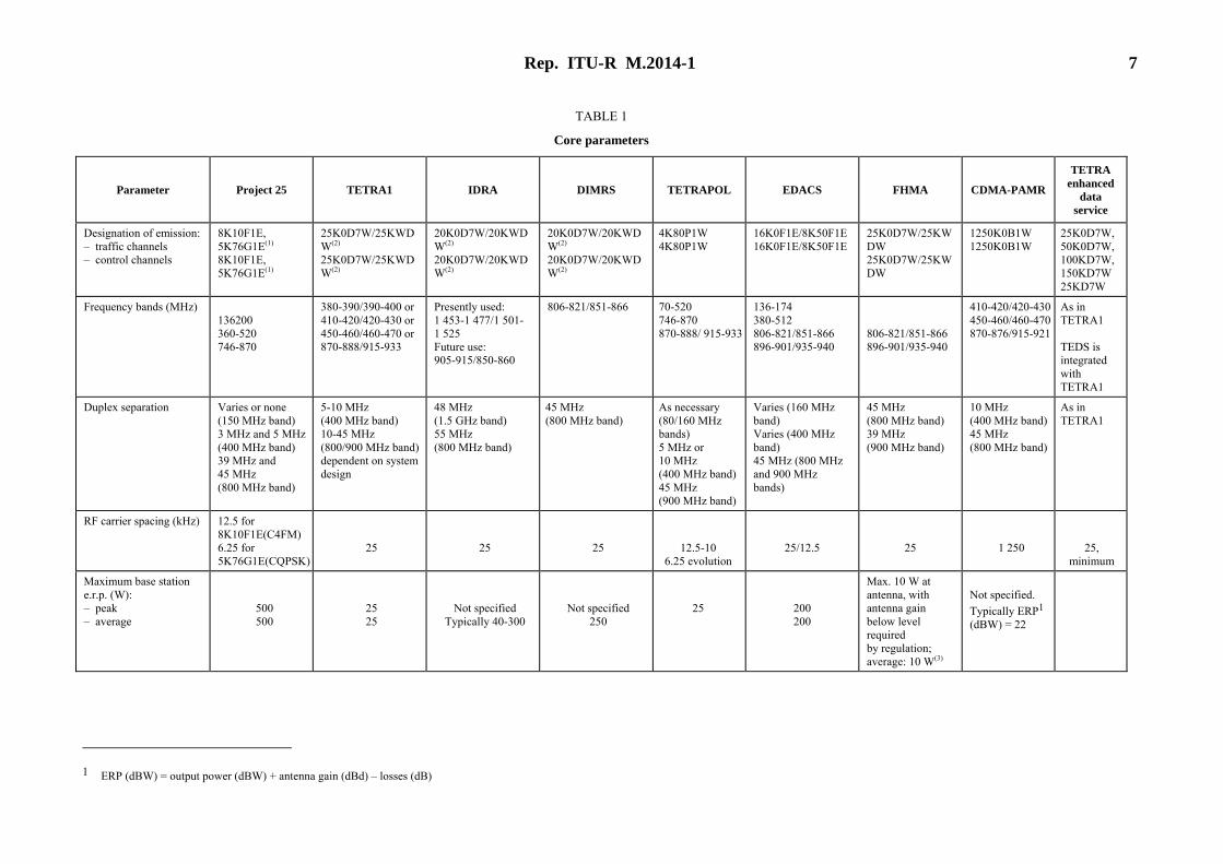
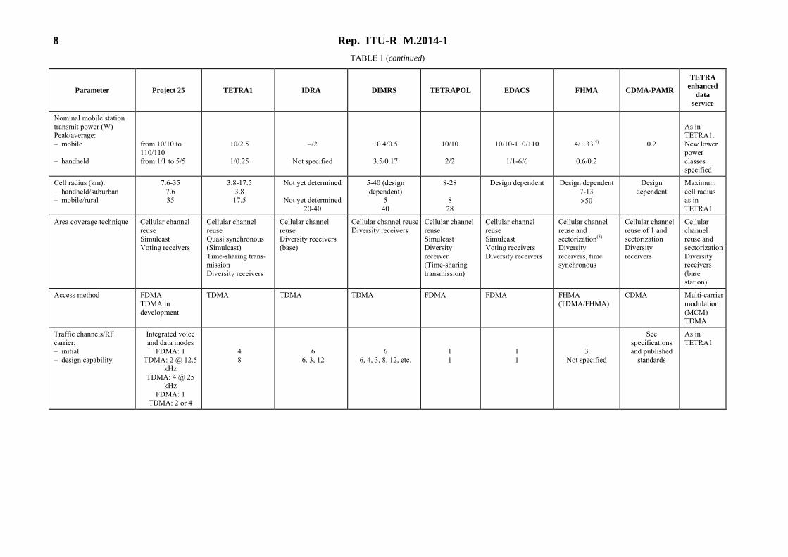
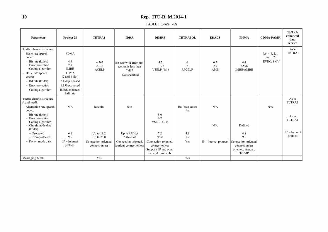
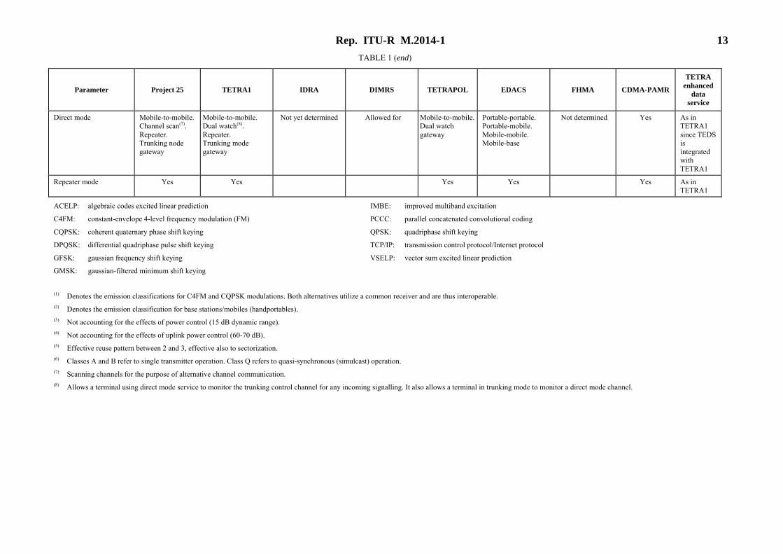
2 Explanation of Table 1 Table 1 presents the core parameters for these systems. In each case, complete specifications are, or will be, available from the relevant authorities as indicated in the Appendices.
Rep. ITU-R M.2014-1 7
TABLE 1
Core parameters
Parameter Project 25 TETRA1 IDRA DIMRS TETRAPOL EDACS FHMA CDMA-PAMR
TETRA enhanced
data service
Designation of emission:– traffic channels – control channels
8K10F1E, 5K76G1E(1) 8K10F1E, 5K76G1E(1)
25K0D7W/25KWDW(2)
25K0D7W/25KWDW(2)
20K0D7W/20KWDW(2)
20K0D7W/20KWDW(2)
20K0D7W/20KWDW(2)
20K0D7W/20KWDW(2)
4K80P1W 4K80P1W
16K0F1E/8K50F1E16K0F1E/8K50F1E
25K0D7W/25KWDW 25K0D7W/25KWDW
1250K0B1W 1250K0B1W
25K0D7W, 50K0D7W, 100KD7W, 150KD7W 25KD7W
Frequency bands (MHz) 136200 360-520 746-870
380-390/390-400 or 410-420/420-430 or 450-460/460-470 or 870-888/915-933
Presently used: 1 453-1 477/1 501-1 525 Future use: 905-915/850-860
806-821/851-866 70-520 746-870 870-888/ 915-933
136-174 380-512 806-821/851-866 896-901/935-940
806-821/851-866 896-901/935-940
410-420/420-430450-460/460-470870-876/915-921
As in TETRA1 TEDS is integrated with TETRA1
Duplex separation Varies or none (150 MHz band) 3 MHz and 5 MHz (400 MHz band) 39 MHz and 45 MHz (800 MHz band)
5-10 MHz (400 MHz band) 10-45 MHz (800/900 MHz band)dependent on system design
48 MHz (1.5 GHz band) 55 MHz (800 MHz band)
45 MHz (800 MHz band)
As necessary (80/160 MHz bands) 5 MHz or 10 MHz (400 MHz band)45 MHz (900 MHz band)
Varies (160 MHz band) Varies (400 MHz band) 45 MHz (800 MHz and 900 MHz bands)
45 MHz (800 MHz band) 39 MHz (900 MHz band)
10 MHz (400 MHz band)45 MHz (800 MHz band)
As in TETRA1
RF carrier spacing (kHz) 12.5 for 8K10F1E(C4FM) 6.25 for 5K76G1E(CQPSK)
25
25
25
12.5-10 6.25 evolution
25/12.5
25
1 250
25, minimum
Maximum base station e.r.p. (W): – peak – average
500 500
25 25
Not specified Typically 40-300
Not specified 250
25
200 200
Max. 10 W at antenna, with antenna gain below level required by regulation; average: 10 W(3)
Not specified. Typically ERP1 (dBW) = 22
1 ERP (dBW) = output power (dBW) + antenna gain (dBd) – losses (dB)
8 Rep. ITU-R M.2014-1 TABLE 1 (continued)
Parameter Project 25 TETRA1 IDRA DIMRS TETRAPOL EDACS FHMA CDMA-PAMR
TETRA enhanced
data service
Nominal mobile station transmit power (W) Peak/average: – mobile – handheld
from 10/10 to 110/110 from 1/1 to 5/5
10/2.5
1/0.25
–/2
Not specified
10.4/0.5
3.5/0.17
10/10
2/2
10/10-110/110
1/1-6/6
4/1.33(4)
0.6/0.2
0.2
As in TETRA1. New lower power classes specified
Cell radius (km): – handheld/suburban – mobile/rural
7.6-35 7.6 35
3.8-17.5 3.8
17.5
Not yet determined
Not yet determined20-40
5-40 (design dependent)
5 40
8-28
8 28
Design dependent Design dependent7-13 >50
Design dependent
Maximum cell radius as in TETRA1
Area coverage technique Cellular channel reuse Simulcast Voting receivers
Cellular channel reuse Quasi synchronous (Simulcast) Time-sharing trans-mission Diversity receivers
Cellular channel reuse Diversity receivers (base)
Cellular channel reuseDiversity receivers
Cellular channel reuse Simulcast Diversity receiver (Time-sharing transmission)
Cellular channel reuse Simulcast Voting receivers Diversity receivers
Cellular channel reuse and sectorization(5) Diversity receivers, time synchronous
Cellular channel reuse of 1 and sectorization Diversity receivers
Cellular channel reuse and sectorization Diversity receivers (base station)
Access method FDMA TDMA in development
TDMA TDMA TDMA FDMA FDMA FHMA (TDMA/FHMA)
CDMA Multi-carrier modulation (MCM) TDMA
Traffic channels/RF carrier: – initial – design capability
Integrated voice and data modes
FDMA: 1 TDMA: 2 @ 12.5
kHz TDMA: 4 @ 25
kHz FDMA: 1
TDMA: 2 or 4
4 8
6 6. 3, 12
6
6, 4, 3, 8, 12, etc.
1 1
1 1
3 Not specified
See specifications and published
standards
As in TETRA1

Rep. ITU-R M.2014-1 9 TABLE 1 (continued)
Parameter Project 25 TETRA1 IDRA DIMRS TETRAPOL EDACS FHMA CDMA-PAMR
TETRA enhanced
data service
Transmission rate (kbit/s)
Integrated voice and data modes
FDMA:9.6 TDMA 2-slot:
TBD, ranging from 9.6-12
TDMA 4-slot: TBD, ranging from
22-24
700 MHz data only modes 50 kHz:
76.8-230.4 kbit/s 100 kHz:
153.6-460.8 kbit/s 150 kHz:
230.4-691.2 kbit/s
36 64 64 8 9.6 36.9 9.6 or 14.4 Support up to 1.8
Mbit/s on the reverse link and up to 3.1 Mbit/s on the forward
link
690 Maximum
Modulation FDMA integrated voice and data modes: QPSK-c family includes C4FM and CQPSK
TDMA voice modes:
2-slot: TBD; QPSK-c family (includes C4FM and CQPSK) and CPM under consideration
4-slot: TBD; CPM under consideration
700 MHz data-only modes
50 kHz: QPSK 100 kHz: 16-QAM 150 kHz: 64-QAM
π/4-DQPSK M16-QAM (M = 4) M16-QAM (M = 4) GMSK GFSK π/4 SQPSK BPSK, QPSK, 8PSK, 16-QAM
π/4-DQPSK, π/8-D8PSK,
4-QAM, 16-QAM, 64-QAM
10 Rep. ITU-R M.2014-1 TABLE 1 (continued)
Parameter Project 25 TETRA1 IDRA DIMRS TETRAPOL EDACS FHMA CDMA-PAMR
TETRA enhanced
data service
Traffic channel structure: – Basic rate speech codec: – Bit rate (kbit/s) – Error protection – Coding algorithm – Basic rate speech codec: – Bit rate (kbit/s) – Error protection – Coding algorithm
FDMA
4.4 2.8
IMBE TDMA
(2 and 4 slot) 2.450 proposed 1.150 proposed IMBE enhanced
half rate
4.567 2.633
ACELP
Bit rate with error pro-tection is less than
7.467 Not specified
4.2 3.177
VSELP (6:1)
6 2
RPCELP
6.5 2.7
AME
4.4 5.596
IMBE/AMBE
9.6, 4.8, 2.4,
and 1.2 EVRC, SMV
As in TETRA1
Traffic channel structure (continued): – Alternative rate speech codec: – Bit rate (kbit/s) – Error protection – Coding algorithm – Circuit mode data (kbit/s) – Protected – Non-protected – Packet mode data
N/A
6.1 9.6
IP – Internet protocol
Rate tbd
Up to 19.2 Up to 28.8
Connection-oriented,connectionless
N/A
Up to 4.8/slot 7.467/slot
Connection-oriented,(option) connectionless
8.0 6.7
VSELP (3:1)
7.2 None
Connection-oriented, connectionless
Supports IP and other network protocols
Half rate codec tbd
4.8 7.2 Yes
N/A
N/A
IP – Internet protocol
Defined
4.8 9.6
Connection-oriented, connectionless
oriented, standard TCP/IP
N/A
As in TETRA1
As in TETRA1
IP – Internet protocol
Messaging X.400 Yes Yes

Rep. ITU-R M.2014-1 11 TABLE 1 (continued)
Parameter Project 25 TETRA1 IDRA DIMRS TETRAPOL EDACS FHMA CDMA-PAMR
TETRA enhanced
data service
Control channel structure (number of channel types):
– Common control channel – Associated control channel – Broadcast control channel
2
3
2
2 3 2
1 2 1
(Option: 5)
– Slot information channel: 1 – Primary control channel: 3 – Temporary control channel: 1 – Dedicated control channel: 1 – Associated control channel: 1
5 2 1
1 1 1
5
1 TDMA slot downlink control, 3 slot uplink access Slow associated, 450 bit/s; fast associated cycle stealing Provided
See specifications
As in TETRA1 As in TETRA1 As in TETRA1
Delay spread equalization capability (µs)(6)
Class A – 50 Class Q – 50
Class A – no equa-lization Class B – 55.5 Class Q – 111.1
Class A – no equa-lization Class B – no equa-lization Class Q – N/A
Class A – 39.8 without equalizer Class B – 65.5 without equalizer Class Q – N/A
No equalization needed
Class A – 52 Class Q – 52
Class A – no equa-lization Class B – no equa-lization Class Q – no equa-lization
See specifications
Use of multi-carrier channels eliminates the need for equalization in QAM channels. PSK channels same as TETRA1

12 Rep. ITU-R M.2014-1 TABLE 1 (continued)
Parameter Project 25 TETRA1 IDRA DIMRS TETRAPOL EDACS FHMA CDMA-PAMR
TETRA enhanced
data service
Channel coding Integrated voice and data for FDMA. BCH code for network ID. Trellis codes for data. Golay & Hamming codes for voice. Reed-Solomon codes for embedded signals. Integrated voice and data for TDMA. TBD for network ID. TBD for data. TBD codes for voice. TBD codes for embedded signals
Convolutional codes with interleaving plus error detection
Multirate trellis coding with interleaving plus error detection and bit Prioritization/ convolutional codes with interleaving plus error detection
Multirate trellis coding with interleaving plus error detection and bit prioritization
Convolutional codes with interleaving plus error detection
Control BCH/repeat.Digital voice custom with repeat. Data repeat
Variable rate convolutional with long interleaving, selective priority protection for encoded voice bits, partial repetition, and channel state enhanced Viterbi algorithm; error detection (cyclic redundancy check (CRC))
Convolutional codes with interleaving. Turbo codes
PCCC turbo codes for the payload. Partitioned Reed-Muller block codes for the header
Encipherment – security levels – multi-algorithm – multikey – encipherment control – over the air rekeying
Types 1, 2, 3 and
4
Yes Yes Yes Yes
Air interface is exportable plus
authentification. Plus end-to-end encryption user definable up to the highest level of
security Yes Yes Yes Yes
Not specified Allowed for Yes
Yes Yes Yes Yes
Type 1, 3, 4
Yes Yes No Yes
Not specified, designed on a “provisions for” concept
Yes See specifications
As in TETRA1
Handover Yes Yes Option Yes Yes Yes Yes Hand-off (Yes) Yes
Inter-system roaming capability
Yes Yes Yes Yes Yes Yes Yes Yes Yes
Design capability for multiple operators (systems) in same area
Yes Yes Yes Yes Yes Yes Allowed for Yes Yes
Rep. ITU-R M.2014-1 13 TABLE 1 (end)
Parameter Project 25 TETRA1 IDRA DIMRS TETRAPOL EDACS FHMA CDMA-PAMR
TETRA enhanced
data service
Direct mode Mobile-to-mobile. Channel scan(7). Repeater. Trunking node gateway
Mobile-to-mobile. Dual watch(8). Repeater. Trunking mode gateway
Not yet determined Allowed for Mobile-to-mobile.Dual watch gateway
Portable-portable. Portable-mobile. Mobile-mobile. Mobile-base
Not determined Yes As in TETRA1 since TEDS is integrated with TETRA1
Repeater mode Yes Yes Yes Yes Yes As in TETRA1
ACELP: algebraic codes excited linear prediction IMBE: improved multiband excitation
C4FM: constant-envelope 4-level frequency modulation (FM) PCCC: parallel concatenated convolutional coding
CQPSK: coherent quaternary phase shift keying QPSK: quadriphase shift keying
DPQSK: differential quadriphase pulse shift keying TCP/IP: transmission control protocol/Internet protocol
GFSK: gaussian frequency shift keying VSELP: vector sum excited linear prediction
GMSK: gaussian-filtered minimum shift keying
(1) Denotes the emission classifications for C4FM and CQPSK modulations. Both alternatives utilize a common receiver and are thus interoperable. (2) Denotes the emission classification for base stations/mobiles (handportables). (3) Not accounting for the effects of power control (15 dB dynamic range). (4) Not accounting for the effects of uplink power control (60-70 dB). (5) Effective reuse pattern between 2 and 3, effective also to sectorization. (6) Classes A and B refer to single transmitter operation. Class Q refers to quasi-synchronous (simulcast) operation. (7) Scanning channels for the purpose of alternative channel communication. (8) Allows a terminal using direct mode service to monitor the trunking control channel for any incoming signalling. It also allows a terminal in trunking mode to monitor a direct mode channel.

14 Rep. ITU-R M.2014-1
Appendix 1 to Annex 1
General description of the TETRA system
1 Introduction TETRA is a high-performance mobile radio system which has been developed primarily for professional users such as the emergency services and public transport. The TETRA suite of mobile radio specifications provide a comprehensive radio capability encompassing trunked, non-trunked and direct mobile-to-mobile communication with a range of facilities including voice, circuit mode data, short data messages and packet mode services. TETRA supports an especially wide range of supplementary services, many of which are exclusive to TETRA.
TETRA is designed to operate in the bands below 1 GHz and the 25 kHz channel structure allows it to fit easily into existing PMR frequency bands.
The specifications cover three distinct telecommunication services corresponding to: – voice plus data; – packet data optimized; and – direct mode.
The packet data optimized (PDO) standard is based on the same physical radio platform as the TETRA25 voice plus data standard but implementations are not expected to interoperate at the physical layer. Full interoperability is foreseen at OSI layer 3.
Direct mode provides direct mobile-to-mobile communications when outside the coverage of the network or can be used as a secure communications channel within the network coverage area. It will interoperate with TETRA25 both at OSI layer 1 and OSI layer 3.
2 Services
2.1 Teleservices Clear speech or enciphered speech in each of the following: – individual call (point-to-point), – group call (point-to-multipoint), – acknowledged group call, – broadcast call (point-to-multipoint one way).
2.2 Bearer services Individual call, group call, acknowledged group call, broadcast call for each of the following: – circuit mode unprotected data 7.2, 14.4, 21.6, 28.8 kbit/s, – circuit mode protected data (low) 4.8, 9.6, 14.4, 19.2 kbit/s, – circuit mode protected data (high) 2.4, 4.8, 7.2, 9.6 kbit/s, – packet connection-oriented data, – packet connectionless data.

Rep. ITU-R M.2014-1 15
2.3 Supplementary services supported
2.3.1 PMR type supplementary services Access priority, pre-emptive priority, priority call.
Include call, transfer of control, late entry.
Calls authorized by dispatcher, ambience listening, discreet listening.
Area selection.
Short number addressing.
Talking party identification.
Dynamic group number assignment.
2.3.2 Telephone type supplementary services List search call.
Call forwarding – unconditional/busy/no reply/not reachable.
Call barring – incoming/outgoing calls.
Call report.
Call waiting.
Call hold.
Calling/connected line identity presentation.
Calling/connected line identify restriction.
Call completion to busy subscriber/on no reply.
Advice of charge.
Call retention.
2.4 Security aspects The TETRA system is designed to ensure high levels of security. The security objectives are listed below: Correct charging: primarily of interest to commercial systems. Authenticity: proving the true identity of the communicating parties and of
the network. Confidentiality of communication: protection against unauthorized reading of transmitted
information. Integrity of communication: protection against unauthorized modification of transmitted
information. Privacy: privacy of people using or operating the network, e.g.
personal information, identities, location. Traffic flow confidentiality: to prevent disclosure of information which can be inferred
from observing traffic patterns. Monitoring: to permit authorized monitoring of communications,
uninhibited by the security mechanisms. Security management: to enable administration of a secure network.

16 Rep. ITU-R M.2014-1
3 Overview of the system The functional architectures for voice and data, and PDO are shown in Figs. 1 and 2, including their respective standardized interfaces.
4 System specifications Refer to Table 1.

Rep. ITU-R M.2014-1 17
4.1 Logical channels The following logical channels are defined: – common control channel (CCCH) comprising:
– main control channel (MCCH), – extended control channel (ECCH).
These channels deal with control information addressed to or received from MSs not involved in a circuit mode call;
– associated control channel (ACCH) comprising: – fast associated control channel (FACCH), – stealing channel (STCH), – slow associated control channel (SACCH).
These channels deal with control information intended for or received from mobile stations involved in a circuit mode call;
– broadcast common control channel (BCCCH) comprising: – broadcast synchronization channel (BSCH), – broadcast network channel (BNCH). These channels carry the downlink system broadcast information;

18 Rep. ITU-R M.2014-1
– traffic channels (TCH) comprising: – speech traffic channel (TCH/S), – speech or data traffic channels (TCH/7.2, TCH/4.8, TCH/2.4). These channels carry the circuit mode voice or data traffic information.
4.2 TDMA frame structure – Voice and data The TETRA frame structure, shown in Fig. 3, has four slots per TDMA frame. This is further organized as 18 TDMA frames per multiframe of which one frame per multiframe is always used for control signalling. This eighteenth frame is called the control frame and provides the basis of the SACCH.
The circuit mode voice or data operation traffic from an 18-frame multiframe length of time is compressed and conveyed within 17 TDMA frames, thus allowing the eighteenth frame to be used to control signalling without interrupting the flow of data. Besides the basic TDMA frame structure described above, there is a hyperframe imposed above the multiframe structure. This is for long repeat frame purposes such as encipherment synchronization. Furthermore, it can be seen that each time-slot is of 510 modulation bits in duration.
4.3 Burst structure – PDO The PDO access schemes are statistical multiplexing for the downlink and statistical multiple access for the uplink. The carrier separation is 25 kHz.
The basic radio resources are sub bursts, transmitting information at a modulating rate of 36 kbit/s. On the uplink there are four types of sub bursts. On the downlink, there are two types of sub bursts. Figure 4 describes the PDO up and down burst format.

Rep. ITU-R M.2014-1 19
20 Rep. ITU-R M.2014-1
4.4 Traffic channels
4.4.1 Speech traffic channels The speech codec, and the associated error correction and detection mechanisms have been defined in the TETRA standard. Speech frames of 30 ms, each comprising 137 bits provide a net bit rate of 4.567 kbit/s. The coding method, ACELP, has been designed to achieve robustness to transmission errors, and to offer a high quality in the presence of background acoustic noise while using a limited bit rate.
Error correction (consisting of a 1/3 rate punctured convolutional code) and interleaving schemes, to selectively protect the most important bits within the speech frame, have been specified. Furthermore, an error detection mechanism has been included and bad frame replacement techniques can be used, in order to minimize the impairment of the speech quality resulting from speech frames not correctly received.
4.4.2 Data traffic channels Data services of up to 19.2 kbit/s are supported with channel coding and interleaving schemes by using up to four time-slots per TDMA frame.
Unprotected digital bearer services with a bit rate up to 28.8 kbit/s are also supported.
5 Operational characteristics
5.1 Location updating and roaming The mobile station evaluates the received signal and initiates the location updating procedure when necessary.
A location area is the area in which a mobile terminal can move freely without updating the location information maintained in the network. The paging area is the area in which a mobile is paged.
The switching and management infrastructure (SwMI) will page the mobile terminal in every location area where it is registered.
To facilitate mobility management, a mobile terminal may be temporarily registered in a number of location areas so that a mobile terminal may travel freely between the areas without the need to reregister.
Roaming is possible within a TETRA network and between TETRA networks.
5.2 Communication protocols
The communication protocols are layered according to the OSI model and are specified in the TETRA standards.
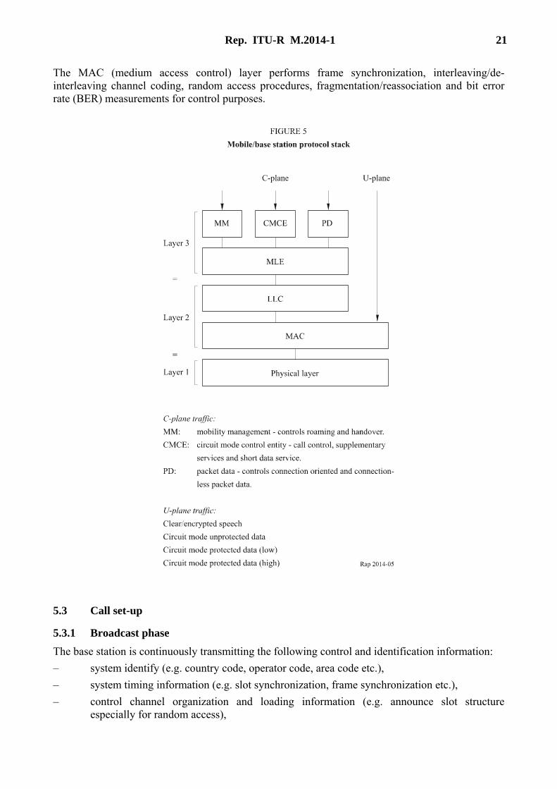
Layers 1 to 3 are subdivided as shown in Fig. 5. The C-plane corresponds to all signalling information, both control and data and also packet mode data traffic. U-Plane information corresponds to circuit mode voice or circuit mode data.
The MM, CMCE and PD are defined in Fig. 5.
The MLE (mobile/base link control entity) performs management of the mobile-to-base/base-to-mobile connection, mobility within a registration area, identity management, quality of service selection, protocol discrimination (i.e., routing to the higher layer applications).
The LLC (logical link control) layer is responsible for scheduling data transmission and retransmissions, segmentation/reassembly, logical link handling.
Rep. ITU-R M.2014-1 21
The MAC (medium access control) layer performs frame synchronization, interleaving/de-interleaving channel coding, random access procedures, fragmentation/reassociation and bit error rate (BER) measurements for control purposes.
5.3 Call set-up
5.3.1 Broadcast phase The base station is continuously transmitting the following control and identification information: – system identify (e.g. country code, operator code, area code etc.), – system timing information (e.g. slot synchronization, frame synchronization etc.), – control channel organization and loading information (e.g. announce slot structure
especially for random access),

22 Rep. ITU-R M.2014-1
– requests for or denial of system registrations.
Information (such as paging messages addressed to a particular mobile or group of mobiles) is transmitted on a per call basis.
5.3.2 Set-up Information is exchanged between the infrastructure and mobile. Five elements of the mobile procedure are: – wake up (if a battery economy mode), – presence check on control channel (if required), – transfer to the traffic channel, – acknowledgement on traffic channel (if required), – traffic information transfer (voice or data).
Further elements need to be taken into account, especially concerning invoking supplementary services during this phase, conveying this information to the infrastructure, checking the subscriber database to ensure these services have been subscribed to. On successful conclusion of this stage, the mobile progresses to the call in progress stage.
5.3.3 Call in progress Terminals are now concerned primarily to communicate with each other rather than signal to the infrastructure. However, even during the traffic phase a substantial amount of control information should be supported to allow “traffic channel acknowledgement”, caller authentication, notification of call waiting, call hold and transfer to waiting, priority pre-empt, include call (IC) and speaker identification during a call.
5.3.4 Call clear down The mobile relinquishes traffic channel and returns to monitoring the control channel. If the call is on “hold” the system will retain details of the mobile and the call reference for subsequent reconnection. The system may optionally retain line resources. When the call is complete all radio and line resources should be cleared of traffic and returned to the resource pool.
5.4 Connection restoration A number of network procedures are supported in the TETRA specifications to provide continuity of service when a mobile encounters adverse propagation effects, moves between different cells or encounters interference. Connection restoration may also be required for traffic reasons; to redistribute the load on a particular cell such as during minimum mode operation; to allow the frequency allocations at a particular cell to be reorganized, or for maintenance or equipment fault reasons.
The responsibility for initiating the connection restoration procedures can rest with the mobile station or with the base station, depending on the reason for restoration.
The mobile station is responsible for monitoring the quality of the downlink transmissions and may request an alternative channel on the same serving cell if interference is encountered or may request service on another cell if the received signal strength drops below a predefined level. The TETRA air interface protocol provides a range of restoration procedures (of different quality) which a network operator may wish to install, and to which users may choose to subscribe. These range from a totally unprepared restoration taking several seconds during which time the connection is broken, to seamless handover where the break in service is imperceptible to the user.
Rep. ITU-R M.2014-1 23
The base station may choose to move the mobile station to another channel on the same servicing cell if interference on the uplink is encountered. The BS may wish to hand-off the call to an adjacent cell if the loading becomes too high on a particular site (load shedding). This would be performed by altering the acquisition and relinquishing criteria defined in the broadcast (BCCCH).
Bibliography
ETSI ETR 086. Terrestrial Trunked Radio (TETRA) system – Technical requirements specification, for (V+D) systems, Packet Data Optimized (PDO) systems, and Security aspects. European Telecommunications Standards Institute, Sophia Antipolis, F-06291 Valbonne Cedex, France.
ETSI prETS.300 392. Terrestrial Trunked Radio (TETRA) – Voice plus Data (V+D), several parts.
ETSI ETR 300. TETRA Designer’s Guide – several parts.
ETSI ETS 300 393-2. Terrestrial Trunked Radio (TETRA) – Packet Data Optimized (PDO), several parts.
ETSI ETS 300 394. Terrestrial Trunked Radio (TETRA) – Conformance testing specification, several parts.
ETSI ETR 300 395. Terrestrial Trunked Radio (TETRA) – TETRA CODEC – several parts.
ETSI ETR 300 396. Terrestrial Trunked Radio (TETRA) – TETRA Direct Mode – several parts.
Appendix 2 to Annex 1
General description of the Project 25 system
1 Services supported Services will be available on Project 25 systems in accordance with system type and other specifications within this Appendix. Where a service is mandatory for a Project 25 system type, such a system must provide that service. Where a service is a standard option, and a Project 25 system provides that service, it shall be provided in compliance to the standard. Technological limitations may preclude some systems from supporting certain services.
1.1 Types of systems Two types of systems are defined: non-trunked (conventional) and trunked. All Project 25 trunked radios shall be capable of operation in both types of systems.
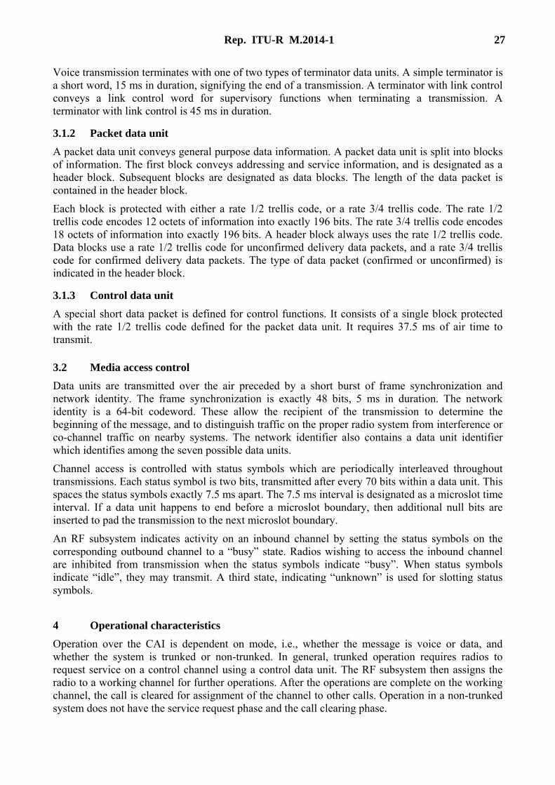
1.1.1 Non-trunked (conventional) Non-trunked (conventional) systems possess no centralized management of subscriber operation or capability. All aspects of system operation are under control of the system users. Operating modes within non-trunked systems include both direct (i.e., radio-to-radio) and repeated (i.e., through an RF repeater) operation.
24 Rep. ITU-R M.2014-1
1.1.2 Trunked Trunked systems provide for management of virtually all aspects of radio system operation, including channel access and call routing. Most aspects of system operation are under automatic control, relieving system users of the need to directly control the operation of system elements.
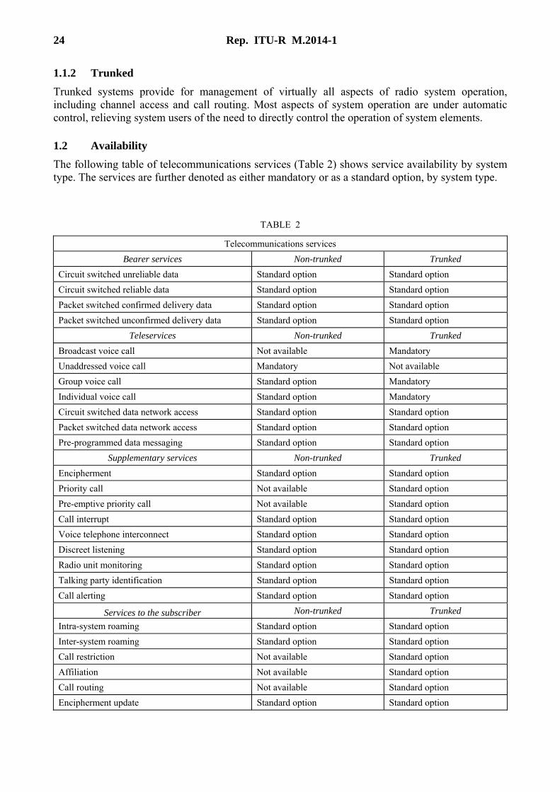
1.2 Availability The following table of telecommunications services (Table 2) shows service availability by system type. The services are further denoted as either mandatory or as a standard option, by system type.
TABLE 2
Telecommunications services Bearer services Non-trunked Trunked
Circuit switched unreliable data Standard option Standard option Circuit switched reliable data Standard option Standard option Packet switched confirmed delivery data Standard option Standard option Packet switched unconfirmed delivery data Standard option Standard option
Teleservices Non-trunked Trunked Broadcast voice call Not available Mandatory Unaddressed voice call Mandatory Not available Group voice call Standard option Mandatory Individual voice call Standard option Mandatory Circuit switched data network access Standard option Standard option Packet switched data network access Standard option Standard option Pre-programmed data messaging Standard option Standard option
Supplementary services Non-trunked Trunked Encipherment Standard option Standard option Priority call Not available Standard option Pre-emptive priority call Not available Standard option Call interrupt Standard option Standard option Voice telephone interconnect Standard option Standard option Discreet listening Standard option Standard option Radio unit monitoring Standard option Standard option Talking party identification Standard option Standard option Call alerting Standard option Standard option
Services to the subscriber Non-trunked Trunked Intra-system roaming Standard option Standard option Inter-system roaming Standard option Standard option Call restriction Not available Standard option Affiliation Not available Standard option Call routing Not available Standard option Encipherment update Standard option Standard option

Rep. ITU-R M.2014-1 25
2 Functional groups
2.1 Mobile end system (MES) In the MES functional group, the term “mobile” is used as in land mobile radio (LMR), which includes all mobile radios, portable radios, and fixed remote radios. The MES functions include the voice and/or data user interface built into a radio.
2.2 Mobile data peripheral (MDP) The MDP functional group includes all mobile, portable, and fixed remote data peripherals. The MDP functions include the data user interface of any data peripheral attached to a radio.
2.3 Mobile routing and control (MRC) The MRC functional group includes functions of voice and/or data routing, as well as control of the mobile radio.
2.4 Mobile radio (MR) The MR functional group includes functions of transmission and reception of all RF signals.
2.5 Base radio (BR) The base radio functional group includes only the functions of modulation and demodulation of the radio frequency energy. Elements within the base radio include the power amplifier, RF front-end, IF selectivity, and end-IF detection device.
2.6 Base audio (BA) The base radio audio functional group includes the functions of frequency/level shaping and signal processing associated with transmitted signals and received signals coupled to the BR. The interface to the BR and base control are manufacturer-specific, and may be at any level or frequency.
2.7 Base control (BC) The base radio control functional group includes the automated control functions of an individual radio.
2.8 Radio frequency control (RFC) The RFC functional group includes all logic for translating user command signalling and control into base radio command signalling and control for one or more base radios. The RFC functions further include all logic for generating command signalling and control to a radio frequency switch (RFS) functional group, if present.
2.9 Radio frequency switch (RFS) The RFS functional group includes all switching for establishing interconnection paths between gateways and base radios, as directed via command and control signalling from an RFC.
2.10 Console The console functional group includes all end system functionality for dispatcher(s); including a dispatcher’s man machine interface, control and audio functions.
26 Rep. ITU-R M.2014-1
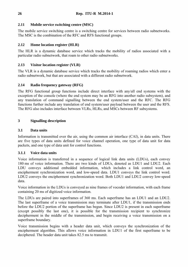
2.11 Mobile service switching centre (MSC) The mobile service switching centre is a switching centre for services between radio subnetworks. The MSC is the combination of the RFC and RFS functional groups.
2.12 Home location register (HLR) The HLR is a dynamic database service which tracks the mobility of radios associated with a particular radio subnetwork, that roam to other radio subnetworks.
2.13 Visitor location register (VLR) The VLR is a dynamic database service which tracks the mobility of roaming radios which enter a radio subnetwork, but that are associated with a different radio subnetwork.
2.14 Radio frequency gateway (RFG) The RFG functional group functions include direct interface with any/all end systems with the exception of the console (where the end system may be an RFG into another radio subsystem), and any translation of command signalling between the end system/user and the RFC. The RFG functions further include any translation of end system/user payload between the user and the RFS. The RFG also includes interface between VLRs, HLRs, and MSCs between RF subsystems.
3 Signalling description
3.1 Data units Information is transmitted over the air, using the common air interface (CAI), in data units. There are five types of data units defined for voice channel operation, one type of data unit for data packets, and one type of data unit for control functions.
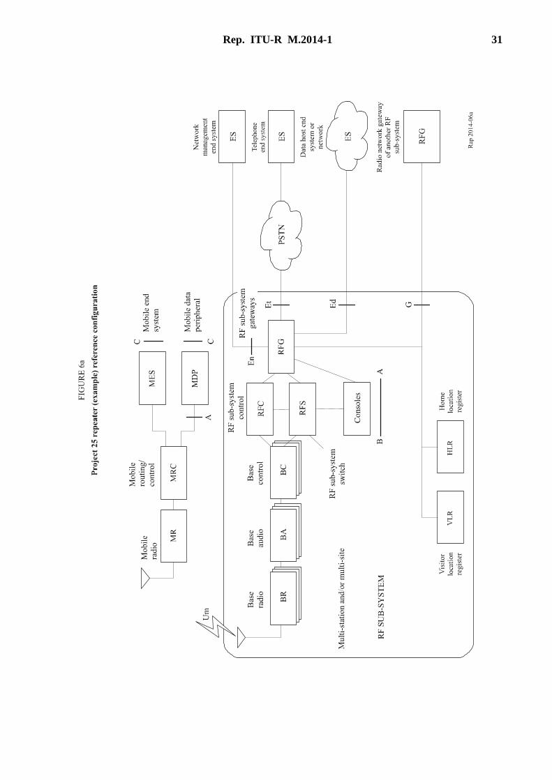
3.1.1 Voice data units Voice information is transferred in a sequence of logical link data units (LDUs), each convey 180 ms of voice information. There are two kinds of LDUs, denoted as LDU1 and LDU2. Each LDU conveys additional embedded information, which includes a link control word, an encipherment synchronization word, and low-speed data. LDU1 conveys the link control word. LDU2 conveys the encipherment synchronization word. Both LDU1 and LDU2 convey low-speed data.
Voice information in the LDUs is conveyed as nine frames of vocoder information, with each frame containing 20 ms of digitized voice information.
The LDUs are paired into superframes of 360 ms. Each superframe has an LDU1 and an LDU2. The last superframe of a voice transmission may terminate after LDU1, if the transmission ends before the LDU2 portion of the superframe has begun. Since LDU2 is present in each superframe (except possibly the last one), it is possible for the transmission recipient to synchronize decipherment in the middle of the transmission, and begin receiving a voice transmission on a superframe boundary.
Voice transmission begins with a header data unit, which conveys the synchronization of the encipherment algorithm. This allows voice information in LDU1 of the first superframe to be deciphered. The header data unit takes 82.5 ms to transmit.
Rep. ITU-R M.2014-1 27
Voice transmission terminates with one of two types of terminator data units. A simple terminator is a short word, 15 ms in duration, signifying the end of a transmission. A terminator with link control conveys a link control word for supervisory functions when terminating a transmission. A terminator with link control is 45 ms in duration.
3.1.2 Packet data unit A packet data unit conveys general purpose data information. A packet data unit is split into blocks of information. The first block conveys addressing and service information, and is designated as a header block. Subsequent blocks are designated as data blocks. The length of the data packet is contained in the header block.
Each block is protected with either a rate 1/2 trellis code, or a rate 3/4 trellis code. The rate 1/2 trellis code encodes 12 octets of information into exactly 196 bits. The rate 3/4 trellis code encodes 18 octets of information into exactly 196 bits. A header block always uses the rate 1/2 trellis code. Data blocks use a rate 1/2 trellis code for unconfirmed delivery data packets, and a rate 3/4 trellis code for confirmed delivery data packets. The type of data packet (confirmed or unconfirmed) is indicated in the header block.
3.1.3 Control data unit A special short data packet is defined for control functions. It consists of a single block protected with the rate 1/2 trellis code defined for the packet data unit. It requires 37.5 ms of air time to transmit.
3.2 Media access control Data units are transmitted over the air preceded by a short burst of frame synchronization and network identity. The frame synchronization is exactly 48 bits, 5 ms in duration. The network identity is a 64-bit codeword. These allow the recipient of the transmission to determine the beginning of the message, and to distinguish traffic on the proper radio system from interference or co-channel traffic on nearby systems. The network identifier also contains a data unit identifier which identifies among the seven possible data units.
Channel access is controlled with status symbols which are periodically interleaved throughout transmissions. Each status symbol is two bits, transmitted after every 70 bits within a data unit. This spaces the status symbols exactly 7.5 ms apart. The 7.5 ms interval is designated as a microslot time interval. If a data unit happens to end before a microslot boundary, then additional null bits are inserted to pad the transmission to the next microslot boundary.
An RF subsystem indicates activity on an inbound channel by setting the status symbols on the corresponding outbound channel to a “busy” state. Radios wishing to access the inbound channel are inhibited from transmission when the status symbols indicate “busy”. When status symbols indicate “idle”, they may transmit. A third state, indicating “unknown” is used for slotting status symbols.
4 Operational characteristics Operation over the CAI is dependent on mode, i.e., whether the message is voice or data, and whether the system is trunked or non-trunked. In general, trunked operation requires radios to request service on a control channel using a control data unit. The RF subsystem then assigns the radio to a working channel for further operations. After the operations are complete on the working channel, the call is cleared for assignment of the channel to other calls. Operation in a non-trunked system does not have the service request phase and the call clearing phase.

28 Rep. ITU-R M.2014-1
4.1 Voice transmit operation Operation of a transmitter for voice messages has three main cases, with several options and variations of each case. The three main cases consist of routine group calls, emergency group calls, and individual calls.
4.1.1 Controls A transmitter may have several controls which affect transmit operations. Controls sufficient for a radio to support all of the call types are defined below. These controls are:
PTT switch – A push-to-talk (PTT) switch is activated when an operator wishes to transmit, and released when a transmission is finished.
Channel selector – The channel selector is a switch or control that allows the operator of a radio to select a radio’s operational parameters. The operational parameters that can be selected include the following items: – transmit frequency, – transmit network access code, – talk group, – other parameters for setting the vocoder and encipherment functions. For example, the
enciphering key variable may be selected.
Emergency switch – The emergency switch is asserted by a radio operator for emergency calling. Once this switch is asserted, the emergency condition remains asserted until it is cleared by a different means, e.g. turning the radio off.
Numeric keypad/display – This allows a radio operator to set numeric values. This is most useful for individual calls.
4.1.2 Call types The different types of calls are defined as follows:
Routine group call – This is a transmission that is intended for a group of users in a radio system. Typically, it is the type of call that is made most often. These calls are typically made when the PTT switch is asserted.
Emergency group call – This is a transmission that is intended for a group of users in a radio system, during an emergency condition. The definition of an emergency condition depends on a system’s operators, but it typically signifies an exceptional condition with more urgency. These calls are typically made after the emergency switch is asserted.
Individual call – This is a transmission which is addressed to a specific individual radio. The individual radio’s address to which the call is directed is called the destination address. These calls are typically made after the destination address is entered into the radio.
4.1.3 Procedures The procedures for each of these calls in the transmitter are based on the procedure for the routine group call. Consequently, that type of call is described first, and then the other types of calls are described.

Rep. ITU-R M.2014-1 29
Routine group call procedure Step 1: PTT. The radio operator asserts the PTT switch.
Step 2: Pre-transmit. The radio selects the channel parameters as determined by the channel selector switch. The radio may check the status symbols, if present, to determine if the channel is busy or idle. If busy, it may optionally hold off the activation of the transmitter until the channel is idle. If the status symbols are not checked, or if the channel is idle, then the radio simply keys the transmitter on the transmit frequency. The radio also activates the voice encoder. The radio also activates the encipherment function, if present.
Step 3: Header data unit. The radio transmits the header data unit with the following selected-information fields: – network access code as determined by the channel selector switch, – manufacturer’s ID, – message indicator, algorithm ID, and key ID are determined by the encipherment
function, – talk group/individual ID is determined by the channel selector switch, as appropriate.
Step 4: Format selection. The following recurrent voice message parameters are set: – network access code as determined by the channel selector switch, – manufacturer’s ID, – emergency bit is set to indicate routine operation, – talk group/individual ID is determined by the channel selector switch, as appropriate, – source ID is set to the unit ID of the radio, – message indicator, algorithm ID, and key ID are determined by the encipherment
function.
Step 5: Transmission. The voice link data units, LDU1 and LDU2, are sent with the message parameters set above in Step 4. The information contents of the link control word is enciphered if specified by the encipherment function. Link control shall only be enciphered if the voice frames are also enciphered. Transmission is sustained until the PTT switch is released.
Step 6: End of Transmission. Transmission terminates when the PTT switch is released, or some other event forces a dekey, and the transmission has reached the end of an LDU. The radio terminates the voice encoder. Then the radio sends a terminator data unit. A radio always sends the simple terminator, consisting of frame synchronization and the network ID word. After termination, the radio notifies the encipherment function to terminate, as defined in the encipherment protocol.
Step 7: Dekey. The radio ceases transmission.
Emergency group call procedure Step 1: Emergency switch. The radio operator asserts the emergency switch. This sets the
emergency condition until it is cleared by some other action, e.g., turning the radio off.
Step 2: Group calls. Activation of the PTT switch now initiates calls that are very much like the routine group call described above. The only difference in procedure is that the emergency bit is asserted to indicate an emergency condition. Group calls can be made repeatedly, and each group call will indicate the emergency condition.

30 Rep. ITU-R M.2014-1
Step 3: Emergency termination. The emergency condition is cleared by turning the radio off. When the radio is turned on, the emergency condition is cleared and routine group calls are made after PTT assertion. In addition to this method, other methods of termination may also be available.
Individual call procedure Step 1: Select called party. The unit ID of the individual radio to be called can be entered into the
radio via a keypad or by some other means. This becomes the destination ID of the call.
Step 2: Make the call. The procedure for group calls is followed, with the following exceptions: – the talk group ID in the header data unit is cleared to the null talk group (0000); – the link control field is formatted with the individual call format, containing the source
ID and destination ID of the call.
4.2 Voice receive operation The operation of a receiver for voice messages consists of three main cases, with variations that depend on the transmitter’s operation. The three main cases are called squelch conditions in this Report. They are: monitor, normal squelch and selective squelch.
As in the case of the transmitter, receiver operation will be affected by the channel selector switch. This switch can select: – receive frequency, – receiver network access code, – talk group, – other parameters for setting the vocoder and encipherment functions. The encipherment
function is particularly significant to the receiver.
An additional radio control which can affect a receiver is the monitor switch. This switch allows the operator of a radio to disable any selective squelch of the receiver so that an operator can hear any sign of voice activity. This can be useful for avoiding collisions on non-trunked channels between voice users.
The types of squelch operation described are defined as follows:
Monitor – This enables the receiver to unmute on any recognizable voice signal. Selective muting based on the network access code, talk group ID, or unit address is not performed. This is analogous to monitor mode in analogue receivers. This is normally activated with a monitor switch.
Normal squelch – This enables the receiver to unmute on any voice signal which has the correct network access code. Voice messages from co-channel users which are using different network access codes will be muted.
Selective squelch – This mutes all voice traffic except that which is explicitly addressed to the radio. Messages which contain the talk group or unit address of the receiver, as well as the network access code, will be received.
Rep. ITU-R M.2014-1 31
32 Rep. ITU-R M.2014-1

Rep. ITU-R M.2014-1 33

34 Rep. ITU-R M.2014-1
Bibliography
APIC Document P25.ETG.04.011 Link Layer Encryption
APIC Document P25.ETG.04.012 Security Services Architectural Overview
TSB102-A. Project 25 System and Standard Definition.
ANSI/TIA102.BAAA-A. Common Air Interface.
TIA102.BAAB-B. CAI Conformance Testing.
ANSI/TIA102.BAAC-A. CAI Reserved Values.
TIA102.BAAD-A. CAI Operational Description for Conventional (non-trunked) Channels.
ANSI/TIA102.BABA. Vocoder Description.
ANSI/TIA102.CAAA-C. Transceiver Measurements and Methods.
ANSI/TIA102.CAAB-C. Transceiver Performance Recommendations.
IS102.AAAA-A. DES Encryption Protocol*.
IS102.BABB-A. Vocoder Mean Opinion Score Test.
IS102.BABC. Vocoder Reference Test.
TSB102.BABD. Vocoder Selection Process.
TSB102.BABE. Vocoder Mean Opinion Score (MOS) Test
TIA102.AABA. Trunking Overview.
ANSI/TIA102.AABB-A. Trunking Control Channel Formats.
ANSI/TIA102.AABC-B. Trunking Control Channel Messages.
ANSI/TIA102.BAEA. Data Overview.
ANSI/TIA102.BAEB. Packet Data Specification.
ANSI/TIA102.BAEC. Circuit Data Specification.
TSB102.BAFA. Network Management Interface Definition.
ANSI/TIA102.AAAA. DES Encryption Protocol
ANSI/TIA102.AAAC. DES Encryption Conformance*.
TIA/EIA TSB102.AACA. OTAR Protocol*
TIA102CABB Interoperability Test Procedures – Over the Air Rekeying (OTAR)
TSB102CABA Interoperability Test Procedures Conventional Voice Equipment
TSB102CABC Interoperability Testing For Voice Operation in Trunked Systems
ANSI/TIA102.AAAD. Block Encryption Protocol
TIA102.AACD. Key Fill Device (KFD) Interface Protocol
ANSI/TIA102.BAEE. Radio Control Protocol Specification.
TIA/102.AAAB. Security Services Overview*.
ANSI/TIA102.BADA. Telephone Interconnect Requirements and Definitions (voice service).
* These documents are referenced for completeness only. The selection of encipherment algorithms should
remain a national option.
Rep. ITU-R M.2014-1 35
TIA102.AABF. Link Control Words.
TSB102.AABG. Conventional Control Messages.
TSB102.AABD. Trunking Procedures.
TSB102.AACB. OTAR Operational Description*.
TSB102.BACC. Inter-RF Subsystem Interface Overview.
TSB102.BACA. ISSI Messages Definition.
TIA102.AACA. OTAR Protocol
ANSI/TIA102.AACC. OTAR Operational Conformance Test
TIA102.AACE. Link Layer Authentication
TSB102.BAGA. Console Interface Overview
TIA102.BAHA. Fixed Station Interface Messages and Procedures
Appendix 3 to Annex 1
General description of the IDRA system
1 Introduction The IDRA system has been developed for use mainly in business-oriented mobile communications applications. Both voice and data communications in the IDRA system offer inter-mobile communications in a single cell and inter-mobile communications between cells, as well as communications between a PSTN user and a mobile subscriber to the IDRA. The IDRA system satisfies the following three fundamental specifications: – voice only, – voice and data (circuit mode data, short message mode data, and packet mode data), – data only (circuit mode data, short message mode data, and packet mode data).
2 Services
2.1 Teleservices Clear speech or enciphered speech in each of the following: – individual call (point-to-point), – group call (point-to-multipoint), – broadcast call (point-to-multipoint, one way), – full-duplex interconnect call, – full-duplex dispatch call (option).

36 Rep. ITU-R M.2014-1
2.2 Bearer services Individual call, group call, and broadcast call for each of the following: – circuit mode protected data 3.044 and 4.8 kbit/slot, – circuit mode non-protected data 7.466 kbit/slot, – packet connectionless data, – packet connection-oriented (option).
2.3 Supplementary services Telephone type supplementary services: – call completion to busy/no-reply subscriber, – call barring incoming/outgoing call, – calling line identity presentation, – calling line identity restriction, – voice operation guide (option), – list search call (option), – call waiting, – advice of charge (option), – short message service (option), – call traffic monitor, – call monitor with late entry, – priority call, – conference call (option), – area selection, – subgrouping call.
Network access supplementary services: – multiple-zone access, – PSTN/public switched data network (PSDN) access.
2.4 Security aspects Special security aspects are not specified, but the system provides a high level of security with authentication and identification.
2.4.1 Authentication
During power up, mobile origination, mobile termination, location updating, supplementary service, and/or short message service.
2.4.2 Identification By individual identification and/or temporary identification.
3 Overview of the system The network approach showing the major architectural components of the system is shown in Fig. 9.

Rep. ITU-R M.2014-1 37
4 System specifications Refer to Table 1.
4.1 Logical channels The following logical channels are defined: – broadcast control channel (BCCH), – common control channel (CCCH), – associated control channel (ACCH), – traffic channel (TCH), – packet channel (PCH), – slot information channel (SICH), – random access channel (RACH),

38 Rep. ITU-R M.2014-1
– temporary control channel (TCCH), – dedicated control channel (DCCH), – radio control channel (RCCH).
4.2 TDMA frame structure The basic frame is prescribed at six slots. The corresponding outbound and inbound frames make a pair. The frame offset, the outbound frame delay relative to the inbound frame, is 70.955 ms.
Conversely, the inbound frame delay, relative to the outbound frame (referred to as transmit-receive offset) can be calculated by the formula, (frame length)-(frame offset). Accordingly, transmit-receive offset is 19.045 ms. Figure 10 shows the general frame structure of the IDRA System.
4.3 Traffic channels
4.3.1 Speech traffic channels The speech codec for voice communication services, including error correction and error detection mechanisms, has not been defined in the Association of Radio Industries and Businesses (ARIB) standard [1995]. However, the ARIB defined the frame structure of the voice channel to have 90 ms speech frames comprised of a total of 672 bits, including the additional bits for error correction. The system operator is free to choose the codec bit rate and error control scheme up to a total of 7.467 kbit/s.
4.3.2 Data traffic channels A circuit data protocol is available for circuit data applications. The circuit-switched data protocol offers a full-duplex packet stream.
Packet data transmission is a planned feature of the IDRA. Airtime for packet transmission is dynamically allocated to the user devices according to their instantaneous communication need. The packet data protocol is planned to allow an auto-bauding capability so that different net burst transfer rates will be available to the user.
Rep. ITU-R M.2014-1 39
5 Operational characteristics
5.1 Location updating and roaming
5.1.1 Roaming Roaming, which enables automatic switching of the infrastructure when a mobile station moves into a different location area, is possible between IDRA systems.
5.1.2 Location updating (option) The IDRA system tracks an individual mobile station location to allow the mobile station to move freely throughout the system and receive or originate calls. Location areas, which are composed of one or more sites, are used to define geographical areas in the system. The mobile terminal must report its position each time it moves between location areas.
5.1.3 Handover (option) The IDRA supports handover between zones and between systems. Handover allows for maintaining the link quality for user connections, minimizing interference, and managing traffic distributions.
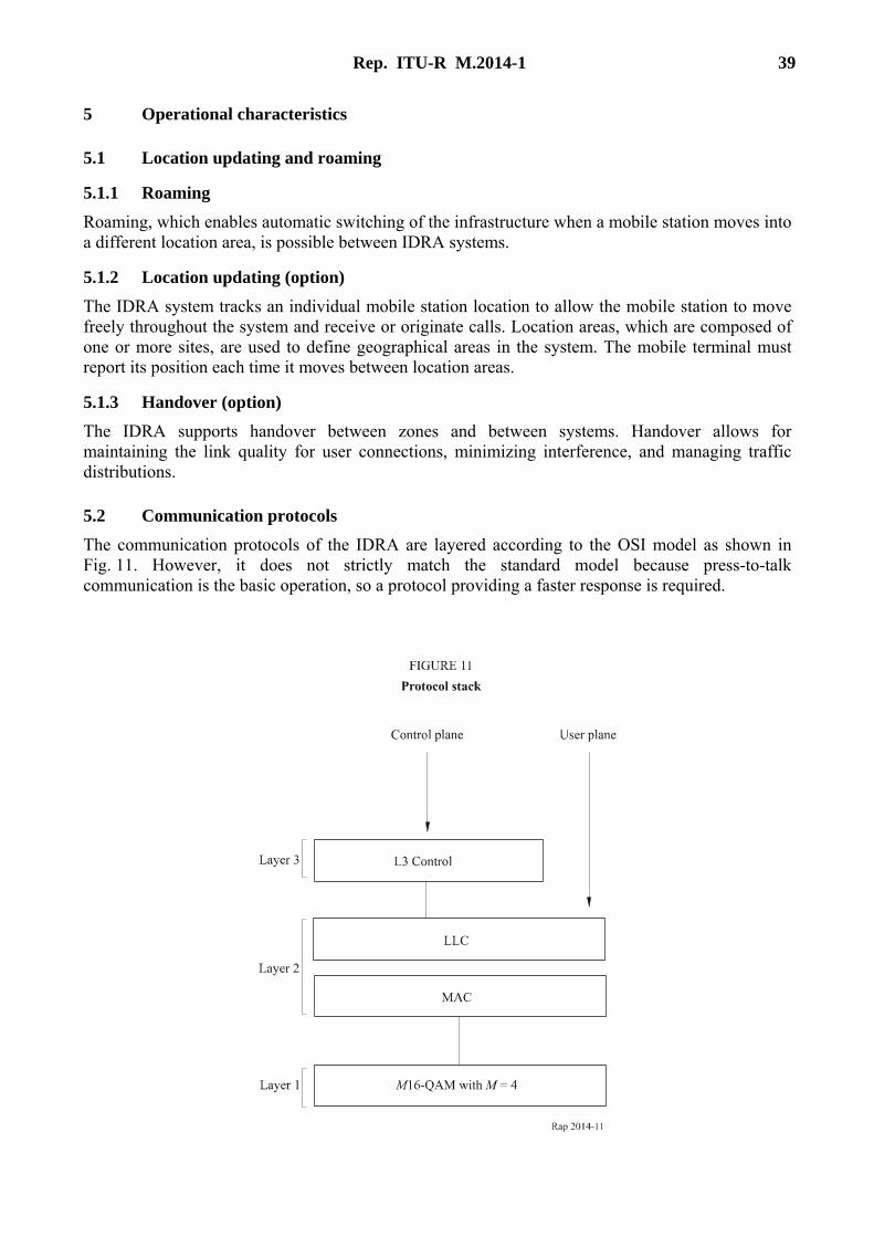
5.2 Communication protocols The communication protocols of the IDRA are layered according to the OSI model as shown in Fig. 11. However, it does not strictly match the standard model because press-to-talk communication is the basic operation, so a protocol providing a faster response is required.

40 Rep. ITU-R M.2014-1
The layers are subdivided as shown below: – Layer 1: this layer specifies the physical structure of the channel (basic slot format, subslot
format, etc.); – Layer 2: this layer specifies communication control between the mobile station and the
infrastructure such as random access control, polling control and time alignment control; – Layer 3: this layer performs as a network layer and is divided into the following three
sublayers: – connection management
call set-up, call management/control, call clear down, etc; – mobility management (option)
location registration, authentication, etc; – radio resource management (option)
cell selection, channel assignment, handover, etc.
5.3 Call set-up
5.3.1 Broadcast phase The base station is continuously transmitting the following control and identification information: – control channel information (e.g. physical structures of control channel for system
identification and call set-up); – system information (e.g. types of communication services and protocols which IDRA can
provide); – restriction information (e.g. types of communication services and protocols which IDRA
now restricts); – system structure information (e.g. location area and target cell information; optional).
5.3.2 Set-up Necessary information is exchanged between the infrastructure and mobile station. The elements of the mobile procedures are: – wake up (if in battery saving mode); – receive the control channel; – exchange the necessary information for call set-up; – receive the traffic channel; – transfer traffic information (voice or data); – registration and authentication (option).
5.3.3 Call clear down The following six procedures are available for call clear down: – the mobile station and the infrastructure clear down when the time limit for communication
is reached; – the infrastructure clears down when the time limit for no response is reached; – the infrastructure clears down when the time limit for no communication is reached; – the mobile station clears down on detection of poor traffic conditions;
Rep. ITU-R M.2014-1 41
– clear down occurs on demand of disconnection from a mobile terminal, a fixed terminal, or a telephone on the PSTN;
– disconnection from the base.
5.4 Connection restoration (option) – The mobile station knows where to monitor from information on (BCCH). – The mobile station continuously measures parameters during call:
– C/(I + N), – RSSI, – primary serving channel.
– When the mobile station detects trouble on primary server: – the mobile station sends in parameter samples, – base evaluates potential servers, – base assigns new server, – the mobile station switches to new server.
Bibliography
ARIB [November, 1995] RCR STD-32A. Integrated Dispatch Radio System. Association of Radio Industries and Businesses. Japan.
Appendix 4 to Annex 1
General description of the DIMRS system
1 Introduction The DIMRS, using new digital technology, fully integrates multiple services including, radio-telephone, paging and dispatch communications into a single infrastructure. DIMRS caters both to users who require an integrated system with enhanced services as well as users who cannot justify the use of a separate pager, cellular phone, dispatch radio and data modem.
2 System services The services provided are:
2.1 Dispatch – Group call. – Private call.

42 Rep. ITU-R M.2014-1
– Call alert. – Push-to-talk (PTT) ID. – Landline to individual private call. – Selective “area” calling.
2.2 Interconnect – Interconnect with other switched networks. – Full-duplex operation. – Handover. – Custom calling features (call waiting, three party calling, dual tone multi-frequency access
to services, call forwarding, busy transfer, no answer transfer, call restrictions, access to information services).
2.3 Roaming services – Intra-system roaming. – Inter-system roaming. – System-to-system handover. – Inter-system calling features. – Registration/de-registration.
2.4 Message paging – Paging. – Short message service.
2.5 Data communications – Circuit mode (protected). – Packet mode:
– with handshake; – without handshake.
3 Authentication mechanism DIMRS provides system security control with an authentication mechanism which may be invoked prior to any chargeable service initiation.
Authentication is used to verify that a mobile station is registered in the system. It may take place during the location updating, mobile origination, mobile termination, supplementary service, and short message service procedures for an interconnect subscriber. For a dispatch only subscriber, authentication will occur during power-up or when a subscriber crosses certain system boundaries such as into another service provider’s area.
Each mobile station user is assigned an individual ID, referred to as an international mobile station identity (IMSI), which is understood by both the dispatch and interconnect call processing programmes. The system will validate the user IMSI each time an interconnect call processing procedure is performed.

Rep. ITU-R M.2014-1 43
For interconnect call processing, a temporary ID, referred to as the temporary mobile station identifier (TMSI), is used to identify the mobile station to the system. This minimizes broadcasting the IMSI over the air.
4 Overview of the system The network approach showing the major architectural components of the system is shown in Fig. 12.
5 System specifications Refer to Table 1.
44 Rep. ITU-R M.2014-1
5.1 Logical channels The following logical channels are defined:
5.1.1 Slot information channel (SICH) A broadcast channel used for transmission of slot control information.
5.1.2 Primary control channel (PCCH) comprising: – broadcast control channel (BCCH). – common control channel (CCCH). – random access channel (RACH).
The PCCH is a multiple access channel used for layer 3 control signalling between the fixed network equipment and the mobile stations. Each cell has one PCCH.
5.1.3 Temporary control channel (TCCH) A temporarily allocated multiple access channel used to provide a means for inbound random access on a channel which is normally reserved access.
5.1.4 Dedicated control channel Supports more extended layer 3 control procedures which would be inefficient if conducted on the PCCH.
5.1.5 Associated control channel (ACCH) The ACCH provides a signalling path on the traffic channel. The main application of the ACCH is to support whatever layer 3 control signalling is required for traffic channel supervision. Bandwidth for the ACCH is obtained by dynamically stealing on the TCH.
5.1.6 Traffic channel (TCH) – Circuit-switched channels These channels are used to transport voice or circuit-switched data traffic. – Packet-switched channel (PCH) These channels will support packet-switched user data communications.
5.2 TDMA frame structure The DIMRS data stream structure, shown in Fig. 13, has six slots per TDMA cycle. A frame structure is further superimposed on this cyclical structure. Inbound and outbound frames consist of 30 240 slots, each 15 ms long. The duration of the frame is 453.6 s.
A hyperframe structure is also defined, in addition to the frame structure. A hyperframe comprises 256 frames, thus, it contains a total of 7 741 440 slots and has a duration of 116 121.6 s (32 h, 15 min, 21.6 s). The large number of slots in the hyperframe is useful for implementing encryption.
5.3 Traffic channels
5.3.1 Speech traffic channels The speech coding technology used is VSELP. Acceptable quality is maintained at channel BER as high as 4-5% in Rayleigh fading, or 10% in static conditions. Error correction is realized through a variable rate strategy whereby the uncoded and trellis-coded 16-QAM modulations are applied selectively to speech bits in accordance with their perceptual significance.
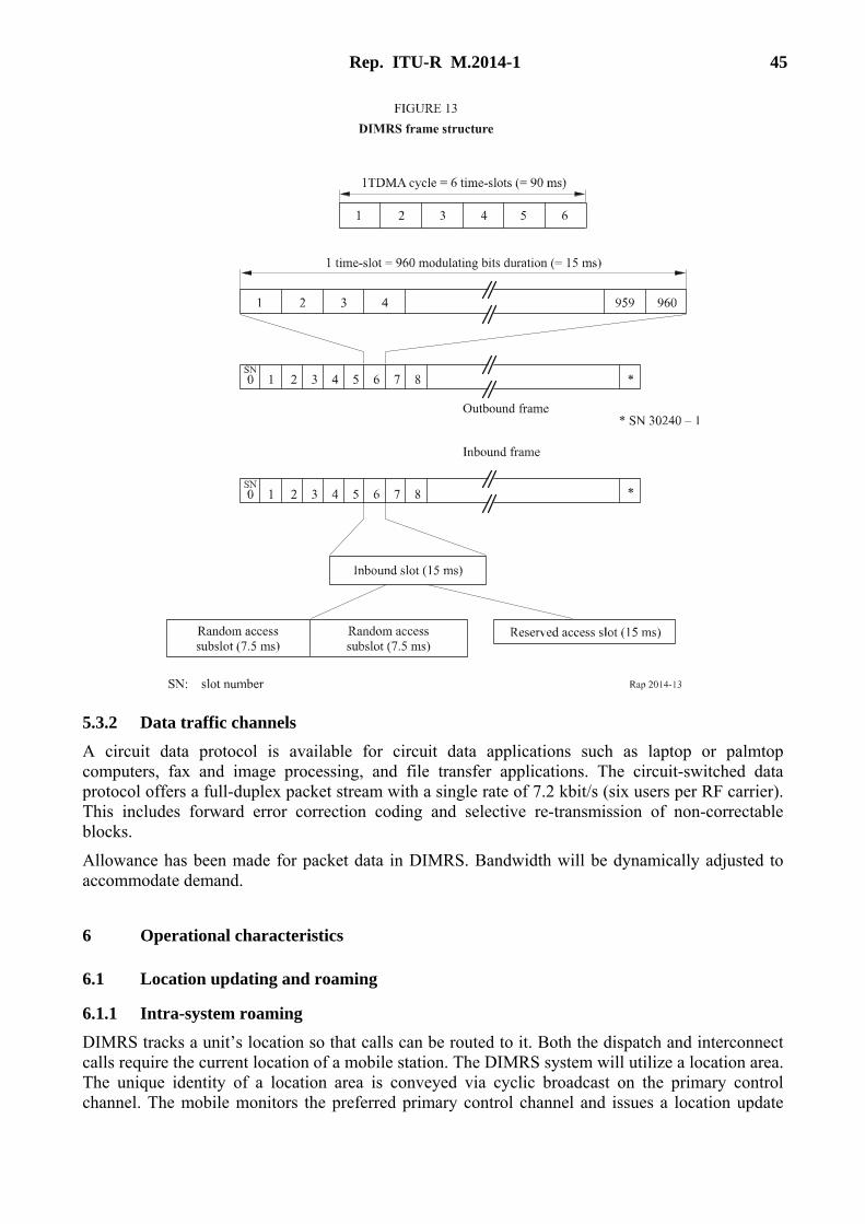
Rep. ITU-R M.2014-1 45
5.3.2 Data traffic channels A circuit data protocol is available for circuit data applications such as laptop or palmtop computers, fax and image processing, and file transfer applications. The circuit-switched data protocol offers a full-duplex packet stream with a single rate of 7.2 kbit/s (six users per RF carrier). This includes forward error correction coding and selective re-transmission of non-correctable blocks.
Allowance has been made for packet data in DIMRS. Bandwidth will be dynamically adjusted to accommodate demand.
6 Operational characteristics
6.1 Location updating and roaming
6.1.1 Intra-system roaming DIMRS tracks a unit’s location so that calls can be routed to it. Both the dispatch and interconnect calls require the current location of a mobile station. The DIMRS system will utilize a location area. The unique identity of a location area is conveyed via cyclic broadcast on the primary control channel. The mobile monitors the preferred primary control channel and issues a location update

46 Rep. ITU-R M.2014-1
request when it finds its location area is no longer supported. The location update request is sent to the VLR that holds the current location of mobile station units operating in that system.
6.1.2 Inter-system roaming The ability to travel freely throughout the single service area and originate or receive calls without regard to current location can be extended to allow mobile stations to travel from one service area to another. A single service area can consist of multiple cells covering a large geographical area (e.g. entire metropolitan area). Alternatively, it may be necessary or desirable to subdivide it into multiple service areas, because of RF coverage gaps, management, or regulatory issues.
6.1.3 System-to-system handover DIMRS supports handover between cells, between location areas, and between systems. Handover allows for maintaining the link quality for user connections, minimizing interference, and managing traffic distributions. The inter-system handover is facilitated in the mobile station’s switch.
6.1.4 Inter-system calling features The mobile station’s in the DIMRS can achieve inter-operability between any system configuration.
6.2 Communication protocols The communication protocols are layered according to the OSI reference model.
6.3 Operation
6.3.1 Dispatch call operation Step 1: A dispatch call is requested via PTT activation. The call request packet is routed to the dispatch application processor (DAP). The DAP recognizes the mobile station unit’s group affiliation and tracks the group
members’ current location area.
Step 2: The DAP sends location requests to each group member’s location area to obtain current sector/cell location.
Step 3: The mobile station units in the group respond with current sector/cell location.
Step 4: The DAP instructs the originating EBTS with packet routing information for all group members.
Step 5: Call voice packets are received by the packet duplicator, replicated, and distributed to the group’s end nodes.
6.3.2 Telephone interconnect operation
6.3.2.1 Call initiation – Inbound
Step 1: Random access procedure (RAP) on primary control channel.
Step 2: Get dedicated control channel assigned.
Step 3: Authentication (optional).
Step 4: Call setup transaction.
Step 5: Get assigned to a traffic channel.
Step 6: Talk.

Rep. ITU-R M.2014-1 47
Step 7: Call termination request on associated control channel.
Step 8: Channel released.
6.3.2.2 Call initiation – Outbound Page mobile station on primary control channel.
Appendix 5 to Annex 1
General description of the TETRAPOL system
TETRAPOL is providing a spectrum efficient, digital narrow-band FDMA, voice and data system for dispatch traffic, which has been developed and validated, and which is operational since 1992. The TETRAPOL land mobile radio specification was defined by the TETRAPOL Forum to provide specifications to the most demanding PMR segment: the public safety and then extended to professional users.
The TETRAPOL applicable band is VHF and UHF, below 1 GHz, with a channel spacing of 12.5 kHz. An evolution to 6.25 kHz spacing is forecast. The access mode is FDMA, with a fully digital constant amplitude modulation GMSK.
The TETRAPOL specifications apply to three different modes: – network mode where the mobile is under the coverage and the control of the infrastructure.
trunking mode and open channel mode are included; – direct mode where the mobile directly communicates with the other terminal; – repeater mode where the mobile communicates with the other terminal through a repeater.
Any combination of these modes can be achieved in the TETRAPOL networks.
1 TETRAPOL model and functional groups A TETRAPOL system is the physical implementation of interconnected elements called subsystems. Physical elements are mapped to functional groups and the interfaces are defined at the reference points (as defined by ITU).
Figures 14, 15 and 16 represent the TETRAPOL models for network, direct and repeater mode with the different network subsystems and the reference points. The subsystems corresponding to functional groups in the TETRAPOL model, which are concerned by the external open interfaces are the following:
– Radio terminal (RT) The RT is the mobile termination unit (MTU) connected to the network through a radio
link.

48 Rep. ITU-R M.2014-1
– Line connected terminal (LCT) The LCT is a terminal connected by a physical connection line locally or remotely to the
network.
– User data terminal (UDT) The UDT is a data terminal (terminal equipment TE) connected to the RT and used for data
services.
– Switching and management infrastructure (SwMI) This is the TETRAPOL network itself split into two subsystems the base station (BS) and
the radio switching unit (RSW).
– Dispatch center (DC) This is the dispatch centre with a dispatch centre server function and a dispatch position
switch function.
– Network management centre (NMC) This is the management centre of different networks for operation and maintenance.
– Message transfer agent MTA X.400 This is the X.400 message handling switch connected to a private or public X.25 network,
acting as a messaging server.
– External data terminal (EDT) This is an EDT, connected through a private or public X.25 network, acting as a data
communication server, data base gateway, private subscriber message base.
– Radio terminal simulator This is the BS Type approval simulator including data.
– BS simulator This the RT type approval simulator including the UDT, RT and SIM simulators.
– Subscriber identity module (SIM) This is the removable module carrying subscriber information and security algorithms.
– Independent digital repeater – (IDR) This is the equipment used in repeater mode for extending the coverage between two
mobiles, irrespective of the SwMI.
– Stand alone dispatch position (SADP) This is the one position terminal for dispatch.
– Gateways Gateways allow connection to other systems like PMR systems (GSM, TETRA...), TCP/IP,
PDN, ISDN, PSTN, private automatic branch exchange (PABX).
– Key management centre (KMC) This is the centre managing the security keys.
The internal subsystems of the TETRAPOL network SwMI are:
– Base station (BS) This is the infrastructure equipment with which the RT communicates through the air
interface. The BS can be split into the BTS and the BSC.

Rep. ITU-R M.2014-1 49
Communication through a line is done via the LABS.
– Radio switch (RSW) The RSW subsystem is the switching part of the TETRAPOL network.
– Base network (BN) This is the elementary network within the SwMI.
2 Reference points This paragraph defines the connection reference points (CRPs) as shown on Figs. 14, 15 and 16. They correspond to the open interfaces in TETRAPOL.
R1 is the reference point between the UDT and the RT.
R2 is the reference point between the UDT and LCT.
R3 is the reference point corresponding to the radio air interface between the RT and the BS.
R4 is the reference point between the LCT and the network SwMI.
R5 is the reference point between the NMC and the network.
R6 is the reference point between the DC and network.
R7 is the reference point corresponding to the PABX gateway.
R8 is the reference point between the MTA X.400 and the network.
R9 is the reference point corresponding to the inter system interface (ISI) between two TETRAPOL networks.
R10 is the reference point between the EDT and the network.
R11 is the reference point corresponding to the inter working unit IWU with other PMR systems.
R12 is the reference point corresponding to the BS – RSW interface.
R13 is the reference point corresponding to the PSTN gateway.
R14 is the reference point corresponding to the ISDN gateway.
R15 is the reference point corresponding to the TCP/IP interface.
R16 is the reference point corresponding to the X.25/PDN gateway.
R17 is the reference point corresponding to the SADP interface.
R18 is the reference point corresponding to the interface between SIM and RT.
R19 is the reference point corresponding to the interface between the KMC and network.
R20 is the reference point between RT (Ud).
R30 is the reference point between the repeater and RT.
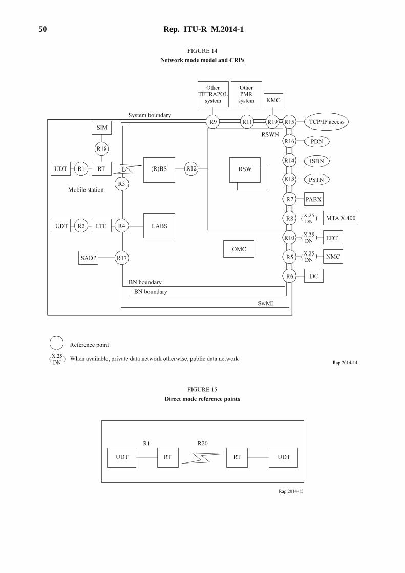
50 Rep. ITU-R M.2014-1

Rep. ITU-R M.2014-1 51
3 Air interface protocol The radio transmission is based on a 160 bits frame, lasting 20 ms, with 8 kbit/s gross throughput physical channels.
A radio channel is one frequency downlink channel from BS to terminal and one frequency uplink channel from terminal to BS, the data rate is 8 kbit/s per channel.
The logical channels are organized from a superframe of 200 consecutive blocks (Fig. 17) lasting 4s. Before transmission information is coded according to a coding scheme depending of the type of burst, this adds redundancy in order to protect information.
There are four types of bursts: speech, data, access and interruption bursts.
The logical channels of the air interface are the following (Figs. 18 and 19): – control channels (CCH) which are a multiplex of different logical channels allocated to the
function performed: access grant, signalling and data, broadcast, paging. The logical channels are mapped on physical channels depending on the burst numbers in the superframe: – random access channel (RACH) used by the terminal for initial access; – dynamic access channel (DACH) used by the terminal for group activation, status
transmission; – signalling and data channel (SDCH) used by the user data terminal UDT and the
network; – broadcast control channel (BCCH); – response channel (RCH) used for random access acknowledgement;

52 Rep. ITU-R M.2014-1
– paging channel (PCH); – stealing channel for signalling (SCH) and transmitter interruption SCH_TE;
– Traffic channels (TCH) used to carry speech or data are: – voice or data channel (TCH).
4 Speech codec Coding is done end to end and as a consequence the codec is only required in the mobile and in the gateway and is not necessary in the infrastructure. This allows, combined with self synchronized end-to-end encryption, simpler coding, faster response time and no echo. Since no transcoding is applied for mobile-to-mobile communication, speech quality is optimized.
Speech is digitized at 6 kbit/s net rate and transmitted on a 8 kbit/s traffic channel.
The speech frame duration of 20 ms corresponds to 120 bits. The coding technique used is RPCELP type, based on analysis by synthesis code excited approach with regular pulse codes. Channel coding is used for protection against transmission errors.
Used in half duplex mode the speech codec does not require specific acoustic processing as echo cancellation.
Speech quality measures have been performed as well as complexity calculations, as controlled by external laboratories. The codec meets the requirements of quality, complexity, delay, documentation and IPR information required.
Rep. ITU-R M.2014-1 53
A complete documentation is available on the speech codec algorithm including test sequences ensuring unambiguous description and bit exact validation of implementation.
In particular very good performance under specific operating conditions have been checked, like: – noisy environment, – double talk conditions, – transmission of tones.
The low complexity of speech coding algorithm allows implementation on a 20 Mips DSP performing radio signal processing of the receiver.
5 Services and network procedures
5.1 Introduction This section describes the services and the features included in the TETRAPOL system.
5.2 Services Services mean telecom services which users can control from the terminals. They could be described in terms of bearer services, teleservices and supplementary services.
5.2.1 Speech services Speech services are listed and described below: – broadcast call, – emergency call, – duplex call – group call, – individual call, – multiple call, – open channel and emergency open channel, – PABX call, – talk group.
5.2.2 Data Services Data services are listed and described below: – access to TCP/IP, – broadcast without acknowledgement, – circuit mode, – connectionless packet mode, – external application messaging, – inter personal messaging (X.400), – fast messaging, – paging, – short data message including status, – X.25 packet mode.

54 Rep. ITU-R M.2014-1
5.2.3 Security services For each mode security services have been designed to counter threats like: – interception of control signals, – masquerading another TETRAPOL infrastructure, – masquerading another user, – jamming, – detection of control channel, – replay, – re-use of user identity, – terminal theft, – traffic analysis, – unauthorised access, – unauthorized interception of voice and data signals anywhere in the system.
The security services are listed as: – prevention and detection of intrusion, – end to end encryption, – identity control of terminals, – login-logout, – mutual authentication (network-terminal), – secured key management (over the air), – security fall back modes, – temporary identity, – terminal disabling, – total inhibition of terminal, – access control, – signalling protection, – security partitioning.
5.2.4 Supplementary services The applicable supplementary services are described and listed below: – access priority, – adaptative area selection, – ambiance listening, – area selection, – automatic call back, – call completion to busy subscriber, – call barring, – call authorized by dispatcher, – call forwarding, – calling line identification,
Rep. ITU-R M.2014-1 55
– call me back, – call waiting, – call transfer, – direct call watch, – discreet listening, – DTMF, – dynamic group number assignment, – include call, – intrusion, – interconnect access, – late entry, – listening restriction, – list search call, – pre-emptive priority, – priority, – priority scanning, – short number addressing, – shortened numbering, – stroke signal, – talking party identification.
5.3 Applications The following applications are supported in TETRAPOL: – access to database, – fax, – file transfer, – GPS, – still video image.
5.4 Network procedures Network procedures are features offered by the network but which the user cannot command from the terminals. They are automatically processed or they are controlled by network managers or by dispatchers. – attach-detach, – call duration limitation, – call re-establishment, – call recording, – call retention, – dynamic regrouping, – group merging, – migration,
56 Rep. ITU-R M.2014-1
– presence check, – power saving mode, – push to talk priority, – roaming, – terminal location (registration), – transmitter power control, – user profile management.
6 Abbreviations A/I Air interface
BS Base station
CCH Control channel
Codec Voice coding decoding
CRP Connection reference point
DB Database
DM Direct mode
DP Dispatch position
DC Dispatch position centre
EDT External data unit
IDR Independent digital repeater
ISI Inter system interface
KMC Key management centre
LCT Line connected terminal
LS Line station
MTA X.400 Message transfer agent X.400
MTU Mobile termination unit
NMC Network management centre
OMC Operation and maintenance centre
PABX Private automatic branch exchange
(P)DN (Public) data network
RP Repeater
PSTN Public switched telephone network
Ri Reference point
RT Radio terminal
RSW Radio switch
SADP Stand alone dispatch position
SIM Subscriber identity module

Rep. ITU-R M.2014-1 57
ST System terminal
SwMI Switching and management infrastructure
TE Terminal equipment
TCP/IP Transmission control protocol/Internet protocol
UDT User data terminal
7 Document references The TETRAPOL specification is a multipart document which consists of the following parts:
PAS001-1 General network design This part contains the reference model, the functional specifications, the protocol
architecture and the principles of the main mechanisms.
PAS001-2 Radio air interface This part describes the radio channel coding, multiplexing, modulation.
PAS001-3 Air interface protocol This part contains the air interface protocol description including the protocol data
units PDUs.
PAS001-4 Gateway to MTA X.400 This part contains the gateway protocol to X.400 messaging.
PAS001-5 Interface to dispatch centre This part contains the interface to the dispatch centre.
PAS001-6 Line connected terminal interface This part describes the interface protocol between the network and the line
connected terminal.
PAS001-7 Codec This part contains the exact bit description of the codec and the relevant tests.
PAS001-8 Radio conformance tests This part contains the mobile and base station radio conformance tests conforming
to ETS 300-113 (22).
PAS001-9 Protocol conformance tests This part describes the air interface protocol conformance tests.
PAS001-10 Inter system interface This part describes the inter system interface protocol between two TETRAPOL
systems.
PAS001-11 Gateway to external networks This part describes the gateways to fixed networks X.25, RNIS, PSTN and to
PABX.
PAS001-12 Network management centre interface This part contains the protocol description of the network management centre
(NMC) interface.
58 Rep. ITU-R M.2014-1
PAS001-13 User data terminal and radio terminal interface This part contains the protocol description of the user data terminal (UDT) (terminal
equipment (TE)) to the radio terminal (mobile termination unit (MTU)) interface.
PAS001-14 Mobile station and base station simulators This part describes the simulators of radio terminal and base station (BS). These
simulators include the RT simulator for the UDT and the UDT simulator for the RT. The EDT simulator is also included, with the RSW simulator for data.
PAS001-15 Gateway to external data terminal (EDT) This part describes the gateway to EDT in messaging application.
PAS001-16 Security This part describes the TETRAPOL security mechanisms and SIM interface but is
available only under controlled disclosure procedure.
TTR1 Guide to TETRAPOL features This part is a designer guide to give information on characteristics and choices in
the system.
PAS001-18 Base station (BS) to the radio switch (RSW) interface This part describes the protocol between the BS and the switch RSW.
PAS001-19 Stand alone dispatch position interface
Appendix 6 to Annex 1
General Description of the EDACS system
1 Introduction The EDACS is an advanced two-way trunked radio system operating on 25 kHz or 12.5 kHz channelization in VHF, UHF, 800 MHz and 900 MHz frequency bands. The development of specifications based on EDACS technology provide backward compatibility and interoperability with the large existing base of EDACS equipment and systems, globally.
The EDACS specification provides features and functions intended on satisfying requirements for public safety, industry, utility and commercial users.
2 Communication modes The following communication modes are supported: – digital voice: all call types, group, group emergency, individual and system all call, are
supported; – digital data: individual calls are supported;
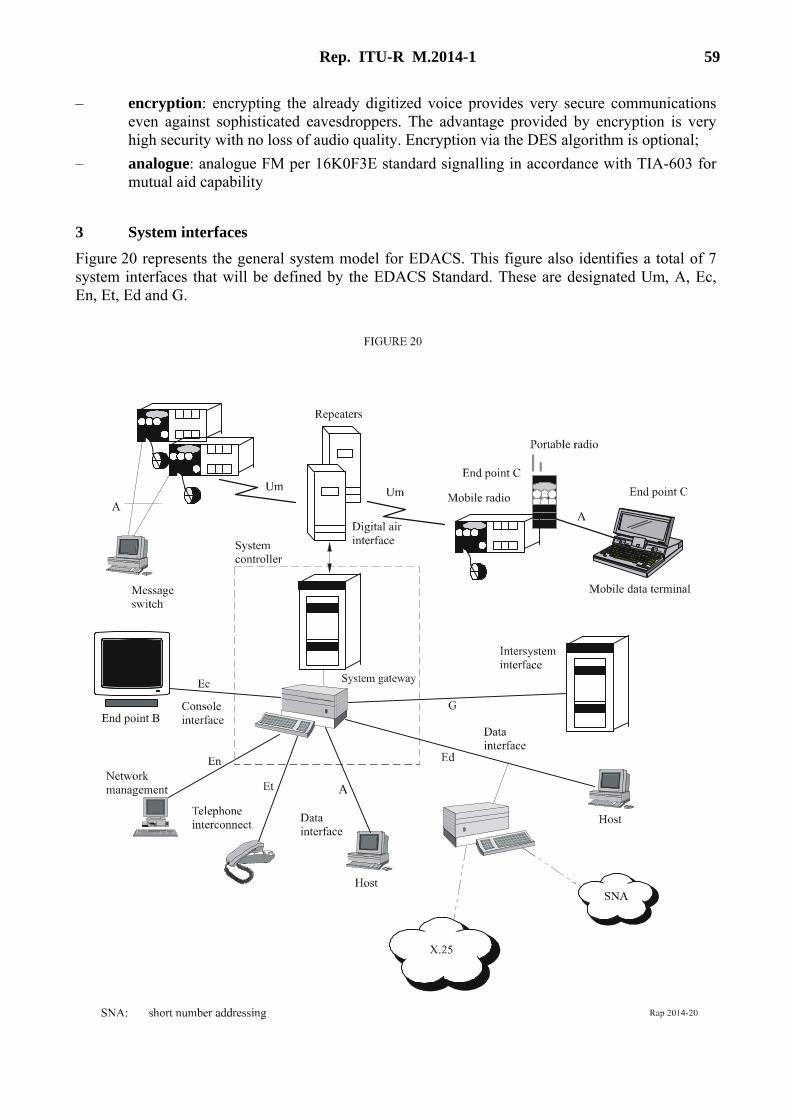
Rep. ITU-R M.2014-1 59
– encryption: encrypting the already digitized voice provides very secure communications even against sophisticated eavesdroppers. The advantage provided by encryption is very high security with no loss of audio quality. Encryption via the DES algorithm is optional;
– analogue: analogue FM per 16K0F3E standard signalling in accordance with TIA-603 for mutual aid capability
3 System interfaces Figure 20 represents the general system model for EDACS. This figure also identifies a total of 7 system interfaces that will be defined by the EDACS Standard. These are designated Um, A, Ec, En, Et, Ed and G.

60 Rep. ITU-R M.2014-1
3.1 Digital air interface The digital air interface, Um, is required for every EDACS implementation. This interface defines all of the digital signalling that is required for communication between the base repeaters and the terminals (portable and mobile radios). One channel bit rate and modulation technique are used for all voice and data communications and, for single-channel operation, control, voice, and data features can be integrated into a common channel.
3.2 Mobile data terminal interface EDACS terminals may support a port through which laptops, terminals or other terminal unit peripherals may be connected. This interface, A, allows communication between a terminal unit and a peripheral.
3.3 Console interface The interface between a system controller and a console unit is the console interface, Ec. This interface provides for control of certain system functions and features via the console unit.
3.4 Network management interface The interface between a system controller and a network management device is the network management interface, En. This interface provides for control of components of the system via the standard network management protocol (SNMP).
3.5 Telephone interconnect interface The interface between a system controller and a telephone network is the telephone interconnect interface, Et. Either analogue or ISDN telephone interfaces are supported.
3.6 Data interface The interface between a system controller and a computer network is called the data interface, Ed. This interface supports connection of the radio system to an established computer network via Internet protocol (IP).
3.7 Intersystem interface Individual radio systems (subsystems) can be interconnected into larger systems via the intersystem interface, G. This interface will also permit systems of different frequency bands and technologies to be interconnected together. This interface supports ISDN.
4 Standardized features and services A fundamental attribute in meeting the communication needs of today as well as in the future is the EDACS proven migration path. EDACS products and services are designed to be compatible with past, present and future technologies. As an Extended Life TechnologyTM, EDACS continues to evolve to accommodate new features and services that are compatible with systems sold since 1987 as well as provide a migration plan to integrate this technology with future, spectrally efficient EDACS F-TDMA prism systems.
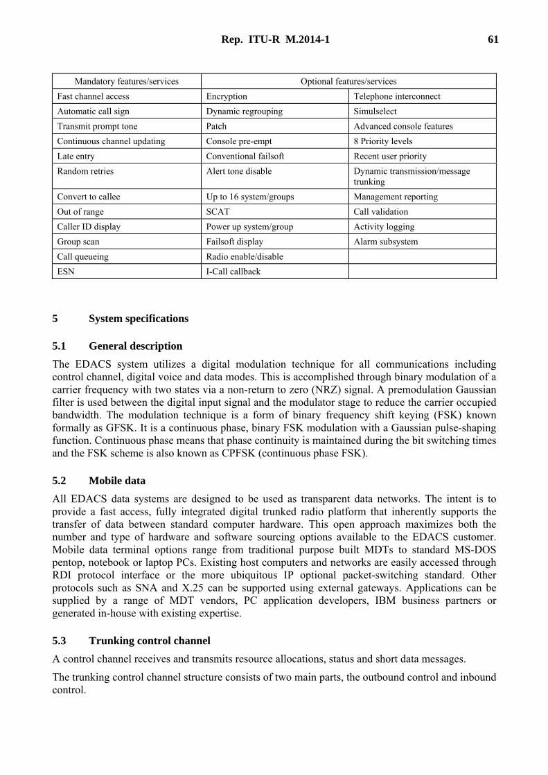
Rep. ITU-R M.2014-1 61
Mandatory features/services Optional features/services Fast channel access Encryption Telephone interconnect Automatic call sign Dynamic regrouping Simulselect Transmit prompt tone Patch Advanced console features Continuous channel updating Console pre-empt 8 Priority levels Late entry Conventional failsoft Recent user priority Random retries Alert tone disable Dynamic transmission/message
trunking Convert to callee Up to 16 system/groups Management reporting Out of range SCAT Call validation Caller ID display Power up system/group Activity logging Group scan Failsoft display Alarm subsystem Call queueing Radio enable/disable ESN I-Call callback
5 System specifications
5.1 General description The EDACS system utilizes a digital modulation technique for all communications including control channel, digital voice and data modes. This is accomplished through binary modulation of a carrier frequency with two states via a non-return to zero (NRZ) signal. A premodulation Gaussian filter is used between the digital input signal and the modulator stage to reduce the carrier occupied bandwidth. The modulation technique is a form of binary frequency shift keying (FSK) known formally as GFSK. It is a continuous phase, binary FSK modulation with a Gaussian pulse-shaping function. Continuous phase means that phase continuity is maintained during the bit switching times and the FSK scheme is also known as CPFSK (continuous phase FSK).
5.2 Mobile data All EDACS data systems are designed to be used as transparent data networks. The intent is to provide a fast access, fully integrated digital trunked radio platform that inherently supports the transfer of data between standard computer hardware. This open approach maximizes both the number and type of hardware and software sourcing options available to the EDACS customer. Mobile data terminal options range from traditional purpose built MDTs to standard MS-DOS pentop, notebook or laptop PCs. Existing host computers and networks are easily accessed through RDI protocol interface or the more ubiquitous IP optional packet-switching standard. Other protocols such as SNA and X.25 can be supported using external gateways. Applications can be supplied by a range of MDT vendors, PC application developers, IBM business partners or generated in-house with existing expertise.
5.3 Trunking control channel A control channel receives and transmits resource allocations, status and short data messages.
The trunking control channel structure consists of two main parts, the outbound control and inbound control.
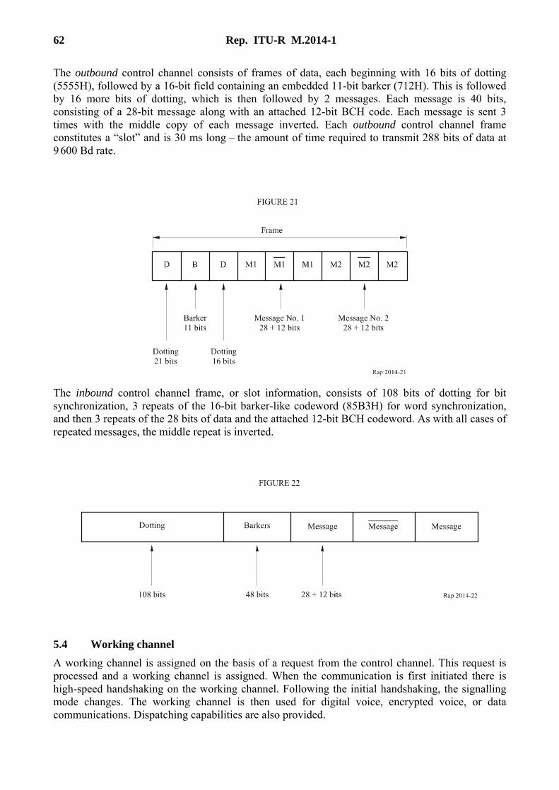
62 Rep. ITU-R M.2014-1
The outbound control channel consists of frames of data, each beginning with 16 bits of dotting (5555H), followed by a 16-bit field containing an embedded 11-bit barker (712H). This is followed by 16 more bits of dotting, which is then followed by 2 messages. Each message is 40 bits, consisting of a 28-bit message along with an attached 12-bit BCH code. Each message is sent 3 times with the middle copy of each message inverted. Each outbound control channel frame constitutes a “slot” and is 30 ms long – the amount of time required to transmit 288 bits of data at 9 600 Bd rate.
The inbound control channel frame, or slot information, consists of 108 bits of dotting for bit synchronization, 3 repeats of the 16-bit barker-like codeword (85B3H) for word synchronization, and then 3 repeats of the 28 bits of data and the attached 12-bit BCH codeword. As with all cases of repeated messages, the middle repeat is inverted.
5.4 Working channel A working channel is assigned on the basis of a request from the control channel. This request is processed and a working channel is assigned. When the communication is first initiated there is high-speed handshaking on the working channel. Following the initial handshaking, the signalling mode changes. The working channel is then used for digital voice, encrypted voice, or data communications. Dispatching capabilities are also provided.
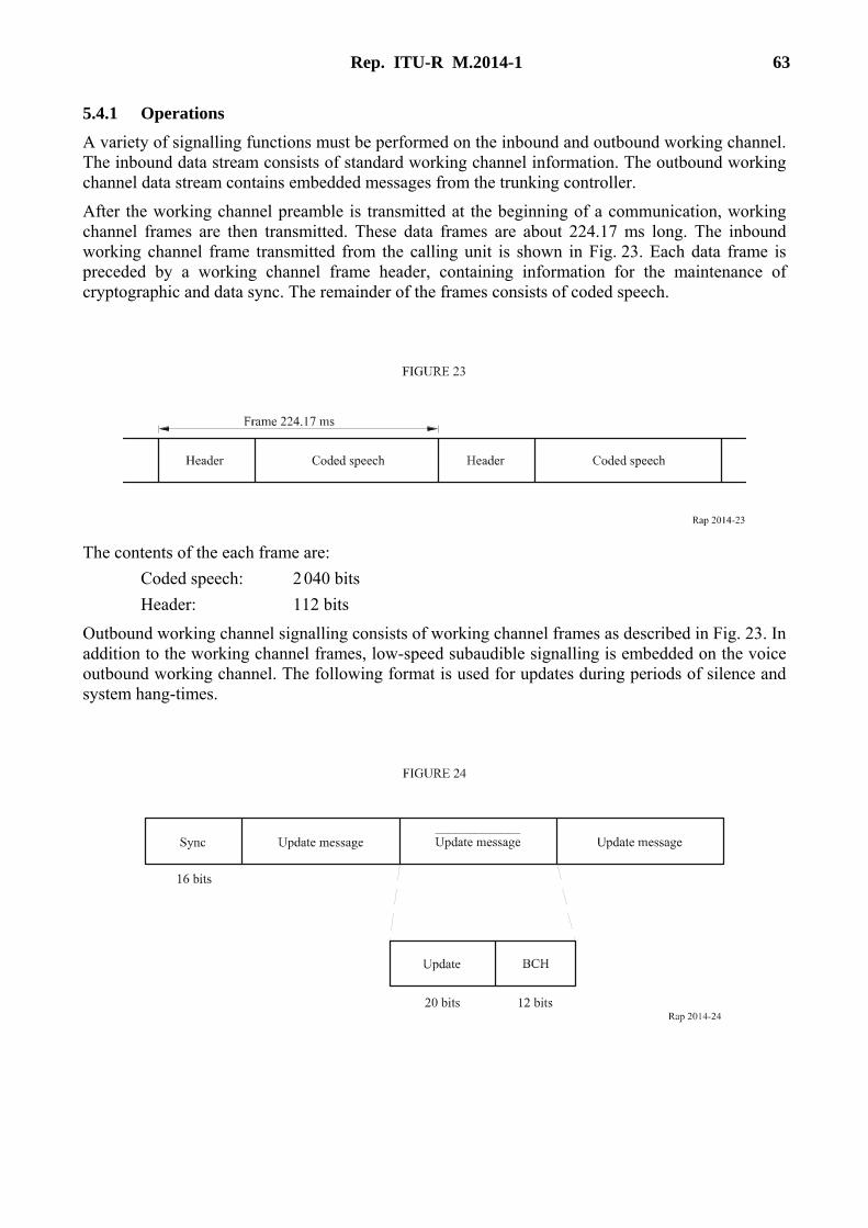
Rep. ITU-R M.2014-1 63
5.4.1 Operations A variety of signalling functions must be performed on the inbound and outbound working channel. The inbound data stream consists of standard working channel information. The outbound working channel data stream contains embedded messages from the trunking controller.
After the working channel preamble is transmitted at the beginning of a communication, working channel frames are then transmitted. These data frames are about 224.17 ms long. The inbound working channel frame transmitted from the calling unit is shown in Fig. 23. Each data frame is preceded by a working channel frame header, containing information for the maintenance of cryptographic and data sync. The remainder of the frames consists of coded speech.
The contents of the each frame are: Coded speech: 2 040 bits Header: 112 bits
Outbound working channel signalling consists of working channel frames as described in Fig. 23. In addition to the working channel frames, low-speed subaudible signalling is embedded on the voice outbound working channel. The following format is used for updates during periods of silence and system hang-times.
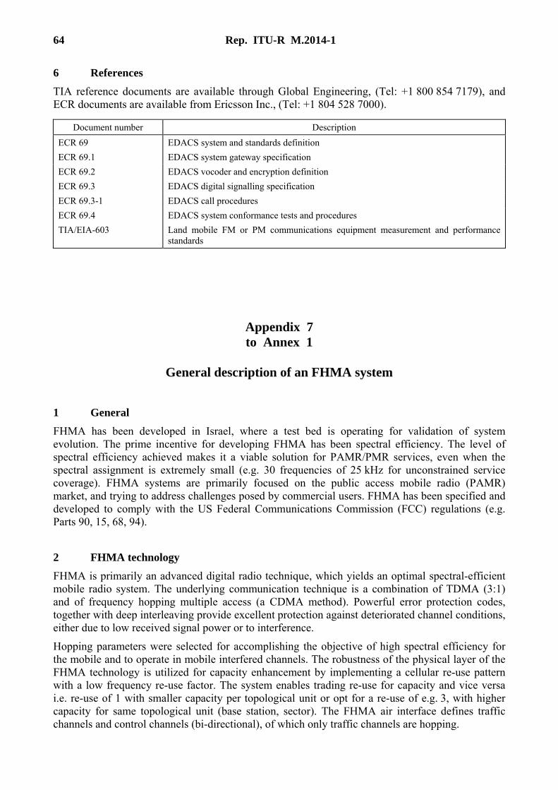
64 Rep. ITU-R M.2014-1
6 References TIA reference documents are available through Global Engineering, (Tel: +1 800 854 7179), and ECR documents are available from Ericsson Inc., (Tel: +1 804 528 7000).
Document number Description ECR 69 EDACS system and standards definition ECR 69.1 EDACS system gateway specification ECR 69.2 EDACS vocoder and encryption definition ECR 69.3 EDACS digital signalling specification ECR 69.3-1 EDACS call procedures ECR 69.4 EDACS system conformance tests and procedures TIA/EIA-603 Land mobile FM or PM communications equipment measurement and performance
standards
Appendix 7 to Annex 1
General description of an FHMA system
1 General FHMA has been developed in Israel, where a test bed is operating for validation of system evolution. The prime incentive for developing FHMA has been spectral efficiency. The level of spectral efficiency achieved makes it a viable solution for PAMR/PMR services, even when the spectral assignment is extremely small (e.g. 30 frequencies of 25 kHz for unconstrained service coverage). FHMA systems are primarily focused on the public access mobile radio (PAMR) market, and trying to address challenges posed by commercial users. FHMA has been specified and developed to comply with the US Federal Communications Commission (FCC) regulations (e.g. Parts 90, 15, 68, 94).
2 FHMA technology
FHMA is primarily an advanced digital radio technique, which yields an optimal spectral-efficient mobile radio system. The underlying communication technique is a combination of TDMA (3:1) and of frequency hopping multiple access (a CDMA method). Powerful error protection codes, together with deep interleaving provide excellent protection against deteriorated channel conditions, either due to low received signal power or to interference.
Hopping parameters were selected for accomplishing the objective of high spectral efficiency for the mobile and to operate in mobile interfered channels. The robustness of the physical layer of the FHMA technology is utilized for capacity enhancement by implementing a cellular re-use pattern with a low frequency re-use factor. The system enables trading re-use for capacity and vice versa i.e. re-use of 1 with smaller capacity per topological unit or opt for a re-use of e.g. 3, with higher capacity for same topological unit (base station, sector). The FHMA air interface defines traffic channels and control channels (bi-directional), of which only traffic channels are hopping.

Rep. ITU-R M.2014-1 65
The Attachments describe the system:
Attachment 1 – FHMA services.
Attachment 2 – Procedures and interfaces.
Attachment 3 – Abbreviations and acronyms.
Attachment 1 to Appendix 7
FHMA Services
The FHMA system has been developed primarily for PAMR users. The services selected are those that are required by the commercial community. Furthermore, special applications have been developed for specific users, especially data applications like embedded automatic vehicle location (AVL), and data dispatch (“Manifest”).
An effort was made in defining the services and applications such as to provide the community of the mobile fleets with all their communications and control needs by a single system. This includes voice telephony, voice dispatch (individual and group), data bearer services, and data specific applications (e.g. AVL, Manifest).
1 Offered services
1.1 Teleservices: All means necessary to provide basic communications and applications (practically all 7 layers of the OSI standard) like: – mobile to mobile telephony and dispatch (trunked) speech communications; – mobile to group voice communications (trunked); – selective access to services, including optional secure communications (primarily
user-furnished algorithms); – telephony communications between a mobile unit and PSTN; – fax capabilities; – data applications like data dispatch (to individuals and groups), and short messaging; – 2-way paging; – automatic vehicle location (GPS based).
1.2 Bearer services: Packet mode data, connection and connection-less oriented, which provide: – nominally 4.8 kbit/s protected data; – 9.6 kbit/s unprotected data;

66 Rep. ITU-R M.2014-1
– 2.4 kbit/s (and 1.2 kbit/s) heavily protected data; – multislot data, up to 28.8 kbit/s unprotected; – multislot data, up to 14.4 kbit/s protected.
1.3 Supplementary services: Services, which are extension to those presently offered, and which may be implemented for satisfying requirements typical to PMR.
2 Voice services
2.1 Telephony
2.2 Group dispatch
2.3 One to One dispatch (121)
3 Data service
3.1 Packet mode connection-oriented data
Standard telephony
Full duplex operation Transcoding done only for calls involving PSTN subscribers
Comfort noise 4.4 kbit/s vocoder, optional 2.4, and 5.55 kbit/s
Unacknowledged group call
Unacknowledged point to multipoint on single TCH with a single call owner at a time and a predefined broadcast group. Group call participants might roam between service areas. A special emergency group dispatch call is defined per fleet
500 ms PTT response time Short group number sent on the air
Acknowledged group call
Similar to unacknowledged group call yet the call owner may get a presence list during call initiation (and possibly later on). Session oriented with hang timer and in-band handshaking over the traffic channel
Broadcast voice message
Unacknowledged one way point-to-multipoint call on single TCH initiated from MS or LS unit
121 Semi-duplex two way point-to-point operation. Session oriented with hang timer and in-band handshaking over the traffic channel. Switching controller (CC) solves contentions
500 ms call-setup
Connection-oriented
Standard TCP/IP connection-oriented service 9.6 kbit/s unprotected 4.8 kbit/s nominal protected 2.4, 1.2 kbit/s heavy protection

Rep. ITU-R M.2014-1 67
3.2 Packet mode connection-less data
3.3 Circuit mode data services
3.4 Short message service
3.5 High speed data
3.6 Network application services FHMA provides the following network application services based on the standard TCP/IP services: – Special data messages (SDM) – A store and forward messaging service provides
subscribers with additional message handling services such as: individual (IDM) and group (GDM) messages, registered, special delivery messages. These services are all accessed through special communications APIs;
– Modem-like (Hayes compatible) communication services (PCCA/AT) that enable subscribers to use standard Modem communication commands (AT/PCCA);
– AVL – Fleet management based on GPS (Etak application on PC) running from subscriber unit (SU), PSTN or leased line access.
3.7 Supplementary services CF Call forward – unconditioned or conditioned (busy, no reply, not reachable)
CW Call waiting – incoming call notification during connection
LE Late entry – allow late comers to join a multipoint voice call
EC Emergency fleet group call
FD Fast dialing (numbers allocated per fleet)
Connection-less
Standard UDP/IP protocol using shared channels (statistical multiplexing)
9.6 kbit/s unprotected 4.8 kbit/s nominal protected 2.4, 1.2 kbit/s heavy protection
Direct Internet connectivity (packet handler integrated in the FHMA network)
Circuit data Extended AT command set Character mode access to packet assembler/ disassembler (pad) (X.28/X.29)
9.6 kbit/s unprotected 4.8 kbit/s nominal protected 2.4, 1.2 kbit/s heavy protection
Protected FAX
Protected fax transmission using extended AT command set
4.8 to 14.4 kbit/s (3 slots)
Short messages
Basic units of 96 bytes with practically unlimited message length (random access is paired with subsequent allocations) Point-to-point and point-to-multipoint
Data Up to 3 TDMA slots
Group and broadcast connections Protected 14.4 kbit/s Unprotected 28.8 kbit/s

68 Rep. ITU-R M.2014-1
CLI Calling/called party identification presentation
CR Call report – leave identity to non available called party for subsequent call back
TPI Talking party indication – inform all party about the identity of the active party in a multipoint connection
LSC List search call – distribute a call to the first available subscriber in a list of attendants
CAD Call authorized by dispatcher – involve operator upon restricted access
SNA Short number addressing – use short abbreviations
AS Area select – establish a call to other party only if it is located inside a selected area
AP Access priority – priority level used to allocate resources in congested networks
PC Priority call – give preference in resource allocation
CH Call hold – interrupt ongoing call but keep the resources engaged
CCBS Call completion to busy subscriber – attempt to complete the call later
ToC Transfer of control – transfer ownership of a multipoint call
PPC Preemptive priority call – as PC but allows disconnecting ongoing calls in order to allocate resources
IC Include call – involve a third party in an active call
BC Barring call – incoming or outgoing call bearing
AoC Advice of charge – charge indication to end-user
DL Discreet listening – facility, which allows tapping into calls
AL Ambiance listening – activating the terminal transmission without giving an indication to the end user
DGNA Dynamic group number assignment – facility for group creation
Attachment 2 to Appendix 7
Procedures and Interfaces
1 Procedures
Handover Mobile controlled handover Mobility management
Air interface: FHMA standard procedures Location registers: Standard MAP based (HLR/VLR)
Call management Air interface: FHMA standard procedures MSC interworking: SS7-ISUP/TUP based with additions necessary for management of voice group calls

Rep. ITU-R M.2014-1 69
2 Interfaces
Attachment 3 to Appendix 7
Abbreviations and Acronyms
AIN Advanced intelligent network
AuC Authentication center
AVL Automatic vehicle location
BHCA Busy hour call attempts
BER Bit error rate
BS Base station
BSC Base station controller
BTS Base transceiver station
CCC Customer care center
CCH Control channel
CMM Channel mode modify
CUG Closed users group
CRC Cycling redundancy checking
EIR Equipment identity register
GC Group call (dispatch)
GCR Group call register (GSM-R)
GoS Grade of service
HLR Home location register
HO Handover
IN Intelligent networks
IWF Inter-working function
MM Mobility management
MO Mobile originated call (outgoing)
Intersystem signalling
SS7-MAP (IS-41C)
Service interworking Distributed connectivity towards PSTN, ISDN and Internet Line-station interface Standard Internet connectivity towards integrated packet handler (DC)
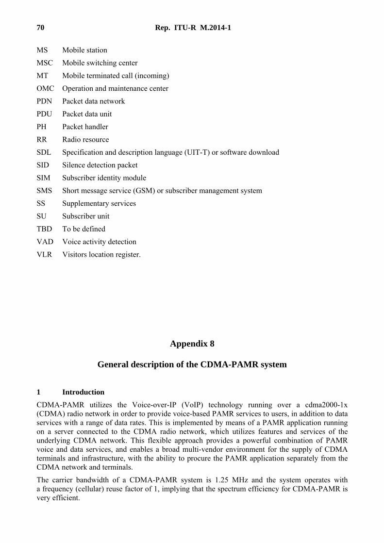
70 Rep. ITU-R M.2014-1
MS Mobile station
MSC Mobile switching center
MT Mobile terminated call (incoming)
OMC Operation and maintenance center
PDN Packet data network
PDU Packet data unit
PH Packet handler
RR Radio resource
SDL Specification and description language (UIT-T) or software download
SID Silence detection packet
SIM Subscriber identity module
SMS Short message service (GSM) or subscriber management system
SS Supplementary services
SU Subscriber unit
TBD To be defined
VAD Voice activity detection
VLR Visitors location register.
Appendix 8
General description of the CDMA-PAMR system
1 Introduction CDMA-PAMR utilizes the Voice-over-IP (VoIP) technology running over a cdma2000-1x (CDMA) radio network in order to provide voice-based PAMR services to users, in addition to data services with a range of data rates. This is implemented by means of a PAMR application running on a server connected to the CDMA radio network, which utilizes features and services of the underlying CDMA network. This flexible approach provides a powerful combination of PAMR voice and data services, and enables a broad multi-vendor environment for the supply of CDMA terminals and infrastructure, with the ability to procure the PAMR application separately from the CDMA network and terminals.
The carrier bandwidth of a CDMA-PAMR system is 1.25 MHz and the system operates with a frequency (cellular) reuse factor of 1, implying that the spectrum efficiency for CDMA-PAMR is very efficient.

Rep. ITU-R M.2014-1 71
CDMA-PAMR technology is designed for use for PAMR networks, in particular in the following frequency bands: – 410-420/420-430 MHz – 450-460/460-470 MHz – 870-876/915-921 MHz.
In the future, CDMA-PAMR technology will be designed to operate in other frequency bands as demand for efficient digital trunking systems grows globally.
2 Services CDMA-PAMR provides a highly flexible environment for the creation of services and applications, and a powerful combination of PAMR voice and data services. The system could initially be driven by the need to provide high-speed data services for mobile workers, although other PAMR services may also be provided. Services available using CDMA-PAMR technology include, among others:
2.1 Teleservices – Individual voice and data calls (point-to-point) – Push-to-talk (PTT) voice services – Group calls (point-to-multipoint) – Dispatch services – Direct mode operation (DMO) – Prioritization and queuing – Status and short data messages – Packet data/IP services – Simultaneous voice and data – Dynamic group management – Over-the-air reprogramming of terminals – Location services.
2.2 Bearer services – Circuit mode protected data: 1.2, 1.35, 1.5, 2.4, 2.7, 4.8, 9.6, 19.2, 38.4, 76.8, and
153.6 kbit/s. – Packet connection oriented data.
2.3 Supplementary type services CDMA-PAMR provides a wide range of other services and features that have not generally been provided by PAMR or PMR systems in the past, but are likely to be beneficial to PAMR users and operators for a wide range of applications. Some examples include: – Separation of user addressing from network numbering, allowing flexibility in setting up
numbering/addressing schemes for user organizations (and efficient use of scarce network numbering resources).
– Integration with/use of IP-based services such as instant messaging, presence services, intranets, voice-over-IP, end-to-end encryption for voice and data, Web-based services, etc.
– Ability to replay dispatch messages (voice and data) as required.

72 Rep. ITU-R M.2014-1
– Automatic storage and retry of high priority (voice and data) messages until received, with acknowledgement and guaranteed delivery.
– Ability to rapidly set-up an ad hoc group on a temporary basis, based on a variety of possible parameters (including location), e.g. at a particular site for a particular situation involving all those users who happen to be in the vicinity at that time.
CDMA-PAMR also supports a wide range of data applications for users, including: – Short data messages – Telemetry – Database access/interactions – Mobile office applications, e.g. email – Image and file transfer – Video.
2.4 Security aspects CDMA-PAMR provides a full range of security features for both the user and the operator. The set of security features that are available is comprised of features implemented in both the network and the application. The network security features include air-interface encryption and authentication. The VoIP approach used in CDMA-PAMR provides for the convenient implementation of end-to-end security for PAMR voice services, as well as for packet data services and applications.
The enhanced encryption facilities available in the CDMA radio access network allow 128-bit based encryption for both signalling messages and user data (e.g. voice or packet data) between the mobile station and the base station. There is also a unified encryption negotiation and encryption structure for both signalling messages and user data. The features of this enhanced air-interface encryption include: – Signalling messages can be encrypted on both common and dedicated channels. – Uses 64-bit key from authentication process as the cipher key. – Uses one of a number of 128-bit based encryption algorithms. – User data encryption on dedicated channel (or on common channel short data bursts, which
are one type of signalling message). – Encryption algorithms are negotiated during common channel operation. – Encryption can be turned on or off independently for each connected service. – Recovery mechanisms when encryption is out-of-sync between the mobile station and the
base station. – Anti-replay attack mechanism.
The basic authentication facilities available in the CDMA radio access network enable the base station to authenticate the mobile station and set up a cipher key for encryption. The enhanced authentication in the standards ensures the authenticity of the sender and the integrity of signalling messages received over-the-air. Enhanced authentication uses one of two schemes to establish the integrity key of this purpose, one of which employs mutual authentication. The base station is able to set the cipher key size to either 64-bit or 128-bit according to the level of encryption strength required. The major features of this enhanced authentication include: – Signalling messages are integrity protected on both common and dedicated channel (by
attaching a 32-bit message authentication code to the message).

Rep. ITU-R M.2014-1 73
– Under one option to establish the integrity key, the base station authenticates the mobile station and sets up a 64-bit integrity key.
– Under the second option, known as AKA, the base station and mobile station authenticate each other (mutual authentication) and set up a 128-bit integrity key (and a 128-bit cipher key).
– Recovery mechanisms when integrity is out of synchronization between the mobile station and the base station.
– Anti-replay attack mechanism.
In addition to such network-based security features, CDMA-PAMR is also well suited to provide security features at the application level, including end-to-end encryption. As described previously, CDMA-PAMR implements voice services (such as postal, telephone and telegraph (PTT) services) that are transported over packet data services of the radio access network. Such VoIP services can be structured to allow for complete end-to-end encryption of media (e.g. voice) without special support in the infrastructure. Such systems have already been employed commercially in the US for end-to-end secure voice services for government use.
3 Overview of the system CDMA-PAMR is a system that uses CDMA radio technology in order to provide PAMR services to users. The system uses VoIP technology running over a CDMA radio access network, with a PAMR application utilizing services and features from the underlying CDMA and IP networks in order to provide the PAMR services and functionality.
The system essentially consists of the following two parts: – The CDMA radio access network, together with the associated IP data network and
components. – The PAMR application, consisting of a mobile client part running on a mobile terminal, and
a network server part running on servers connected to the network.
The features and functionality provided by CDMA-PAMR address essentially the same user needs as other PAMR technologies. CDMA-PAMR adapts the established and already deployed CDMA radio platform to provide both voice and data services in a PAMR environment. The CDMA-PAMR system has been developed for use in the European digital PAMR bands, and is based upon the cdma2000 standards.
CDMA-PAMR technology supports a multitude of service features, including high-speed data and the push-to-talk capabilities that are important for PAMR networks. The push-to-talk features utilize end-to-end VoIP and the industry standard session initiated protocol (SIP). The push-to-talk facilities may be integrated with related services such as instant messaging, and support the latest advances in standard vocoders and both mobile IP and simple IP for mobile users. With the push-to-talk service, both point-to-point and point-to-multipoint connections are provided. As the standards evolve, the push-to-talk features will evolve also to take advantage of the latest developments.
Figure 25 shows the architecture of a CDMA-PAMR system.

74 Rep. ITU-R M.2014-1
FIGURE 25 CDMA-PAMR system architecture
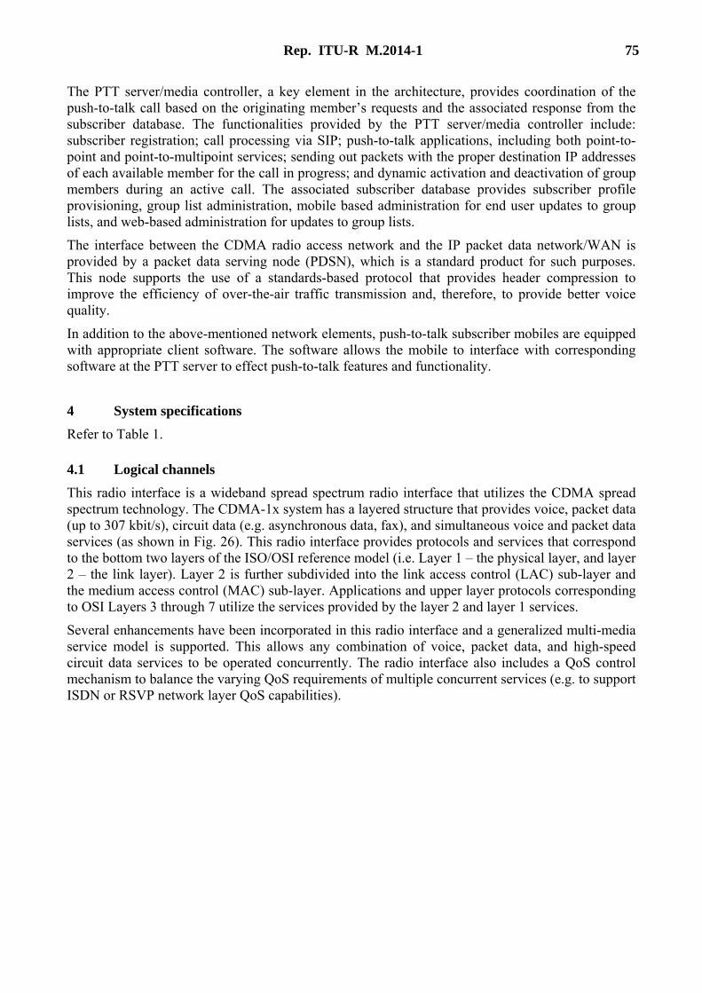
Rep. ITU-R M.2014-1 75
The PTT server/media controller, a key element in the architecture, provides coordination of the push-to-talk call based on the originating member’s requests and the associated response from the subscriber database. The functionalities provided by the PTT server/media controller include: subscriber registration; call processing via SIP; push-to-talk applications, including both point-to-point and point-to-multipoint services; sending out packets with the proper destination IP addresses of each available member for the call in progress; and dynamic activation and deactivation of group members during an active call. The associated subscriber database provides subscriber profile provisioning, group list administration, mobile based administration for end user updates to group lists, and web-based administration for updates to group lists.
The interface between the CDMA radio access network and the IP packet data network/WAN is provided by a packet data serving node (PDSN), which is a standard product for such purposes. This node supports the use of a standards-based protocol that provides header compression to improve the efficiency of over-the-air traffic transmission and, therefore, to provide better voice quality.
In addition to the above-mentioned network elements, push-to-talk subscriber mobiles are equipped with appropriate client software. The software allows the mobile to interface with corresponding software at the PTT server to effect push-to-talk features and functionality.
4 System specifications Refer to Table 1.
4.1 Logical channels This radio interface is a wideband spread spectrum radio interface that utilizes the CDMA spread spectrum technology. The CDMA-1x system has a layered structure that provides voice, packet data (up to 307 kbit/s), circuit data (e.g. asynchronous data, fax), and simultaneous voice and packet data services (as shown in Fig. 26). This radio interface provides protocols and services that correspond to the bottom two layers of the ISO/OSI reference model (i.e. Layer 1 – the physical layer, and layer 2 – the link layer). Layer 2 is further subdivided into the link access control (LAC) sub-layer and the medium access control (MAC) sub-layer. Applications and upper layer protocols corresponding to OSI Layers 3 through 7 utilize the services provided by the layer 2 and layer 1 services.
Several enhancements have been incorporated in this radio interface and a generalized multi-media service model is supported. This allows any combination of voice, packet data, and high-speed circuit data services to be operated concurrently. The radio interface also includes a QoS control mechanism to balance the varying QoS requirements of multiple concurrent services (e.g. to support ISDN or RSVP network layer QoS capabilities).

76 Rep. ITU-R M.2014-1
FIGURE 26 CDMA radio interface architecture

Rep. ITU-R M.2014-1 77
Figure 27 shows the logical and physical channel relationships from the mobile station’s perspective.
FIGURE 27 CDMA radio interface architecture (mobile station)

78 Rep. ITU-R M.2014-1
Table 3 lists the physical channels currently used in CDMA-1x.
TABLE 3
Physical channels in CDMA-1x
Channel name(1) Physical channel
F/R-FCH Forward/reverse fundamental channel F/R-DCCH Forward/reverse dedicated control channel F/R-SCCH Forward/reverse supplemental code channel F/R-SCH Forward/reverse supplemental channel F-PCH Paging channel F-QPCH Quick paging channel R-ACH Access channel F/R-CCCH Forward/reverse common control channel F/R-PICH Forward/reverse pilot channel F-APICH Dedicated auxiliary pilot channel F-TDPICH Transmit diversity pilot channel F-ATDPICH Auxiliary transmit diversity pilot channel F-SYNCH Sync channel F-CPCCH Common power control channel F-CACH Common assignment channel R-EACH Enhanced access channel F-BCCH Broadcast control channel
(1) The notations “F/R” and “forward/reverse” represent two different physical channels (i.e. one forward channel and one reverse channel)
To provide flexible voice services, this radio interface provides the framework and the services to transport encoded voice data in the form of packet data or circuit data traffic.
4.2 Physical layer (L1)
4.2.1 Reverse link Figure 28 shows the reverse CDMA channels received at the base station. The reverse pilot channel is an unmodulated spread spectrum signal used to assist the base station in detecting the mobile station transmission. The mobile station may also insert a reverse power control sub-channel in the reverse pilot channel. The reverse power control sub-channel is used to transmit power control commands for forward link traffic channels. Both the access channel and the enhanced access channel are used by the mobile station to initiate communication with the base station and to respond to paging channel messages.
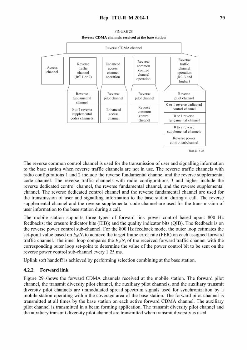
Rep. ITU-R M.2014-1 79
FIGURE 28 Reverse CDMA channels received at the base station
The reverse common control channel is used for the transmission of user and signalling information to the base station when reverse traffic channels are not in use. The reverse traffic channels with radio configurations 1 and 2 include the reverse fundamental channel and the reverse supplemental code channel. The reverse traffic channels with radio configurations 3 and higher include the reverse dedicated control channel, the reverse fundamental channel, and the reverse supplemental channel. The reverse dedicated control channel and the reverse fundamental channel are used for the transmission of user and signalling information to the base station during a call. The reverse supplemental channel and the reverse supplemental code channel are used for the transmission of user information to the base station during a call. The mobile station supports three types of forward link power control based upon: 800 Hz feedbacks; the erasure indicator bits (EIB); and the quality indicator bits (QIB). The feedback is on the reverse power control sub-channel. For the 800 Hz feedback mode, the outer loop estimates the set-point value based on Eb/Nt to achieve the target frame error rate (FER) on each assigned forward traffic channel. The inner loop compares the Eb/Nt of the received forward traffic channel with the corresponding outer loop set-point to determine the value of the power control bit to be sent on the reverse power control sub-channel every 1.25 ms.
Uplink soft handoff is achieved by performing selection combining at the base station.
4.2.2 Forward link Figure 29 shows the forward CDMA channels received at the mobile station. The forward pilot channel, the transmit diversity pilot channel, the auxiliary pilot channels, and the auxiliary transmit diversity pilot channels are unmodulated spread spectrum signals used for synchronization by a mobile station operating within the coverage area of the base station. The forward pilot channel is transmitted at all times by the base station on each active forward CDMA channel. The auxiliary pilot channel is transmitted in a beam forming application. The transmit diversity pilot channel and the auxiliary transmit diversity pilot channel are transmitted when transmit diversity is used.

80 Rep. ITU-R M.2014-1
FIGURE 29 Forward CDMA channels received at the mobile station
The sync channel is used by mobile stations operating within the coverage area of the base station to acquire initial time synchronization. The paging channel is used by the base station to transmit system overhead information and mobile station specific messages. The broadcast channel is used by the base station to transmit system overhead information. The quick paging channel is used by the base station to inform mobile stations, operating in the slotted mode while in the idle state, whether or not to receive the forward common control channel, the broadcast channel, or the paging channel.
The common power control channel is used by the base station for transmitting common power control sub-channels (one bit per sub-channel) for the power control of multiple reverse common control channels and enhanced access channels. The common power control sub-channels are time multiplexed on the common power control channel. Each common power control sub-channel controls a reverse common control channel or an enhanced access channel. The common assignment channel is used by the base station to provide quick assignment of the reverse common control channel. The forward common control channel is used by the base station to transmit mobile station-specific messages. For radio configurations 1 and 2, the forward traffic channels include the forward fundamental channel and forward supplemental code channel.
For radio configurations 3 and higher, the forward traffic channels include the forward dedicated control channel, forward fundamental channel, and forward supplemental channel. Similar to the corresponding reverse traffic channels, these channels are used for transmission of user signalling information to a specific mobile station during a call. The forward traffic channels also include the forward power control sub-channel. It is used to transmit reverse power control commands and is transmitted either on the forward fundamental channel or on the forward dedicated control channel. The reverse traffic channels utilize an 800 Hz feedback power control mechanism similar to that for the forward traffic channel. In addition, the mobile station supports open loop power control.
Downlink soft handoff is achieved by performing diversity combining at the mobile station. Transmit diversity is achieved by transmitting modulation symbols on separate transmit antennas.

Rep. ITU-R M.2014-1 81
4.3 Media access control (MAC) (layer 2) The media access control (MAC) sub-layer provides the following important functions: – Best effort delivery – reasonably reliable transmission over the radio link with a radio link
protocol (RLP) that provides a “best effort” level of reliability. – Multiplexing and QoS control – enforcement of negotiated QoS levels by mediating
conflicting requests from competing services and the appropriate prioritisation of access requests.
– Sophisticated reservation access – capabilities to provide efficient high-speed low latency common channel access.
4.4 Link access control (LAC) (layer 2) The link access control (LAC) sub-layer performs the following important functions: – Delivery of service data units (SDUs) to a layer 3 entity using ARQ (retransmission)
techniques, when needed, to provide reliability. – Building and validating well-formed protocol data units (PDUs) appropriate for carrying
the SDUs. – Segmentation of encapsulated PDUs into LAC PDU fragments of sizes suitable for transfer
by the MAC Sublayer and re-assembly of LAC PDU fragments into encapsulated PDUs. – Access control through “global challenge” authentication. Conceptually, some messages
failing authentication on a common channel should not be delivered to the upper layers for processing.
Address control for delivery of PDUs based on addresses that identify particular mobile stations.
4.5 Signalling (layer 3) Layer 3 signalling provides a flexible structure designed to support a wide range of radio interface signalling alternatives. In addition to supporting the normal mobile network features, layer 3 signalling also supports the following radio related features and capabilities: – Radio configuration negotiation – Quick paging operation (to improve battery life) – Handoff capabilities (i.e. soft handoff, hard handoff, idle handoff, access probe handoff,
and access handoff) – Power control – High-speed data – Enhanced access – Broadcast control operation – Auxiliary pilot support.
Bibliography
TIA/EIA/IS-2000.1-C (and subsequent versions). Introduction to cdma2000 Standards for Spread Spectrum Systems.
TIA/EIA/IS-2000.2-C (and subsequent versions). Physical Layer Standard for cdma2000 Spread Spectrum Systems.
82 Rep. ITU-R M.2014-1
TIA/EIA/IS-2000.3-C (and subsequent versions). Medium Access Control (MAC) Standard for cdma2000 Spread Spectrum Systems.
TIA/EIA/IS-2000.4-C (and subsequent versions). Signalling Link Access Control (LAC) Standard for cdma2000 Spread Spectrum Systems.
TIA/EIA/IS-2000.5-C (and subsequent versions). Upper Layer (Layer 3) Signalling Standard for cdma2000 Spread Spectrum Systems.
TIA/EIA-97-F (and subsequent versions). Recommended Minimum Performance Standard for Base Stations Supporting Dual-Mode Spread Spectrum Cellular Mobile Stations.
TIA/EIA-98-F (and subsequent versions). Recommended Minimum Performance Standards for Dual-Mode Spread Spectrum Mobile Stations.
TIA/EIA/IS-127 (and addenda). Enhanced Variable Rate Codec, Speech Service Option 3 for Wideband Spread Spectrum Digital Systems, January 1997.
TIA/EIA/IS-893. Selectable Mode Vocoder Service Option for Wideband Spread Spectrum Communication Systems, to be published.
TIA/EIA/IS-707-A-2. Data Service Options for Spread Spectrum Systems, Addendum 2, March 2001.
TIA/EIA/IS-835-A (and subsequent versions). cdma2000 Wireless IP Network Standard.
TIA/EIA/IS-683-A (and subsequent versions). Over-the-Air Service Provisioning of Mobile Stations in Spread Spectrum Systems.
TIA/EIA/IS-725-A. Cellular Radio-telecommunications Intersystem Operations – Over-the-Air Service Provisioning (OTASP) & Parameter Administration (OTAPA), July 1999.
TIA/EIA/IS-801-1. Position Determination Service Standard for Dual-Mode Spread Spectrum Systems, February 2001.
Appendix 9
General description of the TETRA enhanced data service system
1 Introduction The core of the TErrestrial Trunked RAdio (TETRA) standard developed by the European Telecommunications Standards Institute (ETSI) has been available since 1994. Since then, ETSI Technical Committee TETRA (TC-TETRA) has been continuously enhancing the standard (the IP packet data capability was added, for example, in 2000), with the aim of providing a state-of-the-art digital mobile-radio system to professional users in both the PMR and PAMR context. A rapid upwards trend in the data speed of mobile-radio networks and the increasing popularity of Internet “contents” and multimedia services at the turn of the new millennium prompted TC-TETRA to develop a Release 2 of the TETRA standard capable of supporting concurrent wideband multimedia applications. TETRA Enhanced Data Service (TEDS) is an outcome of this activity. TEDS is fully integrated with TETRA. TETRA Release 2 standard (due for publication in September 2006) is a new release of the TETRA standard in which TEDS is incorporated [ETSI, 2006].
Rep. ITU-R M.2014-1 83
TEDS is designed to operate, at least initially, in the following frequency bands as used by TETRA before the TEDS enhancement (TETRA1): – 380-390/390-400 MHz – 410-420/420-430 MHz – 450-460/460-470 MHz – 870-876/915-921 MHz.
The TETRA1 air interface was based on 25 kHz channels using л/4-DQPSK modulation and a single carrier 4-slot TDMA access method. TEDS has introduced three new channel bandwidths, i.e. 50, 100 and 150 kHz plus the following four new modulations: – л/8-D8PSK, for a low cost upgrade of existing TETRA1 systems to 50% higher data speed – 4-QAM, for efficient links at TETRA1 coverage edge – 16-QAM, for moderate speeds and range – 64-QAM, for high speeds closer to BS.
The TEDS access method for QAM modulated channels is a multi-carrier modulation (MCM) TDMA using 8, 16, 32 and 48 sub-carriers in 25, 50, 100 and 150 kHz channels respectively. This results in a high tolerance of the multi-path effect without a need for complex equalizers in the receiver.
The use of the above channel bandwidths, modulation types and three coding rates, i.e. 1/2, 2/3 and 1 provides a wide range of raw data rates up to 691 kbit/s (compared to 36 kbit/s in TETRA1) and spectral efficiencies up to 4.6 bit/s/Hz. The users could select their throughput from that available in TETRA1 to an upper limit of about 500 kbit/s in TEDS, depending on application and range requirements.
A TEDS enabled MS accesses the integrated TETRA network via the TETRA1 control channel present in every BS and using a 25 kHz channel and л/4-DQPSK modulation.
2 Services TEDS operates as part of a TETRA Release 2 network. In this way a TEDS enabled TETRA MS has access to all traditional TETRA services: – bearer services (circuit mode data, short data and packet data); – teleservices including the TETRA voice service; – supplementary services.
In addition, such an MS has access to the wideband TEDS IP packet data bearer service. The service access points provided by this bearer service allows TEDS to handle concurrent multimedia applications through a multimedia exchange (MEX) layer. Each application whether single or multimedia could negotiate a set of QoS parameters. These depend on application (or data) class. The following three data classes are defined in TEDS:
a) Background class (best-effort type data requiring high reliability). Examples are: – General file transfer – Transfer of photographs and maps – Reliable delivery of despatch messages with attached maps, plans, photographs and
documents etc. – Secure delivery of patient and client records – Database enquiries e.g. police national computer.
84 Rep. ITU-R M.2014-1
b) Telemetry class (intermittent data requiring moderate reliability and low delay tolerance). Examples are:
– Delivery of medical telemetry from patient to hospital – Vehicular telemetry.
c) Real-time class (data where timely delivery is essential and retransmissions are not permitted). Examples are:
– Voice (VoIP) – Video.
3 Overview of system specifications In order to add high-speed packet data services to the TETRA standard whilst allowing backward compatibility to the existing TETRA1 systems, the following developments have taken place in the TEDS standard: 1) A new physical layer has been defined. 2) The existing TETRA higher protocol layers (upper MAC, LLC and SNDCP) have been
modified to enable transmission of significantly higher-speed IP traffic over the air interface. Also a new optional protocol layer, i.e. MEX layer to handle concurrent multimedia applications has been introduced.
3.1 Physical layer
3.1.1 Physical and logical channels The TEDS air interface is based on a time-division multiple access (TDMA), which guarantees backward-compatibility with the TETRA1 standard. The basic TDMA frame consists of 4 timeslots, each having a duration of 85/6 (14.167) ms. TEDS also offers sub-slots, each of duration 85/12 (7.083) ms, which increase the efficiency of transmission in some cases. In addition, the TDMA structure includes multiframes (18 frames each) and hyperframes (60 multiframes each) as well.
3.1.1.1 Physical channels Each timeslot associated to a pair of RF frequencies, (for uplink and downlink using frequency-division duplexing (FDD)), forms a physical channel. The latter conveys the traffic and signalling messages in the form of logical channels that are packed by the MAC layer, the interface between the higher protocols and the TEDS radio subsystem. The physical content of a timeslot (or subslot), referred to as a TEDS burst, is arranged both in the frequency and time domain according to the symbol patterns outlined in § 3.1.5, and could be any of the following types: 1) Control burst (CB): used by MSs to transmit control messages to the BS. 2) Normal uplink burst (NUB): used by MSs to transmit control or traffic messages to the BS.
Traffic messages here refer to voice and circuit mode data used in PM channels. 3) Random access uplink burst (RAB): used by MSs to transmit random access control
messages to the BS. 4) Normal downlink burst (NDB): The NDB shall be used by the BS to transmit control
messages to the MS. 5) Synchronization continuous downlink burst: used by BSs (with π/4-DQPSK) in continuous
transmission mode to broadcast synchronization messages and to transmit control messages to the MSs. This burst provides the means for synchronization to both TETRA1 and TEDS terminals.

Rep. ITU-R M.2014-1 85
6) Linearization uplink burst (LB): used by the MSs to linearize their transmitters. 7) Linearization downlink burst (LDB): used by the BS to linearize its transmitter.
3.1.1.2 Logical channels The TEDS MAC layer supports both signalling messages and packet data via the following five Control channels (CCHs), also known as logical channels: 1) the broadcast network channel (BNCH-Q) contains control network information that is sent
to all MSs; 2) the signalling channels SCH-Q/D, SCH-Q/U, SCH-Q/HU which indicate full size message
downlink, full size message uplink, and half size (sub-slot) message uplink respectively. Q represents use of QAM modulation, D denotes downlink, representing messages sent by the BS to a specific MS or group of MSs and U denotes uplink, indicating messages sent by an MS to the BS. Each of these channels is sub-divided further according to different combinations of modulation/coding rate and channel bandwidth) The fourth type of SCH is SCH-Q/RA, which contains random access uplink messages, and is associated with only 25 kHz bandwidth, 4-QAM and coding rate r = 1/2;
3) the access assignment channel (AACH-Q) is present on the transmitted downlink slots and contains the assignment of the uplink and downlink slots on each physical channel;
4) the slot information channel (SICH-Q) is used in both uplink (SICH-Q/U) and downlink (SICH-Q/D) to indicate the modulation and coding used in the remainder of the slot or subslot ; and is associated with only 25 kHz bandwidth, 4-QAM and coding rate r = 1/2;
5) the linearization channel (LCH-Q) is used by the BS and MSs to linearize their transmitters.
3.1.1.3 Mapping of logical channels to physical channels The mapping of the above TEDS logical channels into physical channels is summarized in Table 4.
TABLE 4
Mapping of TEDS logical channels into physical channels
Logical channel Direction Burst type
BNCH-Q Downlink NDB AACH-Q Downlink NDB SICH-Q/D Downlink NDB SICH-Q/U Uplink NUB, CB BLCH-Q Downlink LDB CLCH-Q Uplink LB SCH-Q/D Downlink NDB SCH-Q/U Uplink NUB
SCH-Q/HU Uplink CB SCH-Q/RA Uplink RAB
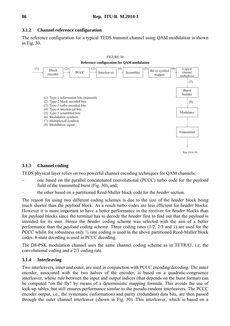
86 Rep. ITU-R M.2014-1
3.1.2 Channel reference configuration The reference configuration for a typical TEDS transmit channel using QAM modulation is shown in Fig. 30.
FIGURE 30 Reference configuration for QAM modulation
3.1.3 Channel coding TEDS physical layer relies on two powerful channel encoding techniques for QAM channels; – one based on the parallel concatenated convolutional (PCCC) turbo code for the payload
field of the transmitted burst (Fig. 30), and; – the other based on a partitioned Reed-Muller block code for the header section.
The reason for using two different coding schemes is due to the size of the header block being much shorter than the payload block. As a result turbo codes are less efficient for header blocks. However it is more important to have a better performance in the receiver for header blocks than for payload blocks since the terminal has to decode the header first to find out that the payload is intended for its user. Hence the header coding scheme was selected with the aim of a better performance than the payload coding scheme. Three coding rates (1/2, 2/3 and 1) are used for the PCCC whilst for robustness only ½ rate coding is used in the above partitioned Reed-Muller block codes. 8-state decoding is used in PCCC decoding.
The D8-PSK modulation channel uses the same channel coding scheme as in TETRA1, i.e. the convolutional coding and a 2/3 coding rate.
3.1.4 Interleaving Two interleavers, inner and outer, are used in conjunction with PCCC encoding/decoding. The inner encoder, associated with the two halves of the encoder, is based on a quadratic-congruence interleaver, whose rule between the input and output indices (that depends on the burst format) can be computed “on the fly” by means of a deterministic mapping formula. This avoids the use of look-up tables, but still ensures performance similar to the pseudo-random interleavers. The PCCC encoder output, i.e., the systematic (information) and parity (redundant) data bits, are then passed through the outer channel interleaver (shown in Fig. 30). This interleaver, which is based on a
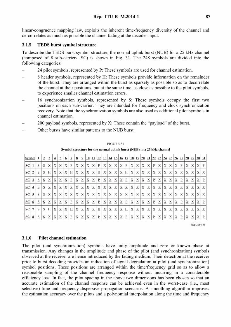
Rep. ITU-R M.2014-1 87
linear-congruence mapping law, exploits the inherent time-frequency diversity of the channel and de-correlates as much as possible the channel fading at the decoder input.
3.1.5 TEDS burst symbol structure To describe the TEDS burst symbol structure, the normal uplink burst (NUB) for a 25 kHz channel (composed of 8 sub-carriers, SC) is shown in Fig. 31. The 248 symbols are divided into the following categories: – 24 pilot symbols, represented by P: These symbols are used for channel estimation. – 8 header symbols, represented by H: These symbols provide information on the remainder
of the burst. They are arranged within the burst as sparsely as possible so as to decorrelate the channel at their positions, but at the same time, as close as possible to the pilot symbols, to experience smaller channel estimation errors.
– 16 synchronization symbols, represented by S: These symbols occupy the first two positions on each sub-carrier. They are intended for frequency and clock synchronization recovery. Note that the synchronization symbols are also used as additional pilot symbols in channel estimation.
– 200 payload symbols, represented by X: These contain the “payload” of the burst. – Other bursts have similar patterns to the NUB burst.
FIGURE 31 Symbol structure for the normal uplink burst (NUB) in a 25 kHz channel
3.1.6 Pilot channel estimation The pilot (and synchronization) symbols have unity amplitude and zero or known phase at transmission. Any changes in the amplitude and phase of the pilot (and synchronization) symbols observed at the receiver are hence introduced by the fading medium. Their detection at the receiver prior to burst decoding provides an indication of signal degradation at pilot (and synchronization) symbol positions. These positions are arranged within the time/frequency grid so as to allow a reasonable sampling of the channel frequency response without incurring in a considerable efficiency loss. In fact, the pilot spacing in the above two dimensions has been chosen so that an accurate estimation of the channel response can be achieved even in the worst-case (i.e., most selective) time and frequency dispersive propagation scenarios. A smoothing algorithm improves the estimation accuracy over the pilots and a polynomial interpolation along the time and frequency

88 Rep. ITU-R M.2014-1
axis is eventually used to estimate the fading samples over other symbols and the sub-carriers that do not carry pilot symbols.
3.1.7 Adaptive selection of modulation and coding according to propagation conditions Link adaptation may be used in TEDS by the BS and MS to improve usage of the channel. This is achieved by the BS and/or MS transmitters changing the modulation type and/or coding rate. The permissible modulation/coding pairs are given in the second column of Table 5. Link adaptation methods may include measurements of the radio link quality and/or the use of BS-MS link adaptation signalling and depends on the data class used.
Adaptive link control signalling from receiver to transmitter helps the transmitter choose the optimum modulation and coding rate on a timescale of 0.5 s or longer.
The link adaptation algorithms will adjust the bit rate to adapt the packet data throughput to the distance from the base station and the prevailing propagation conditions at different locations in the cell.
3.1.8 TEDS throughput Not all combinations of channel bandwidth, modulation type and coding rate are permitted in TEDS channels. The combinations have been limited to those shown in the second column of Table 5. This table also provides an estimate of the throughput, after allowance is made for the pilot symbols, channel coding and lower layer protocol headers and functions. These are technically the “TL-SDU” bit rates, but are close to the true bit rates available to user IP packets in good channel conditions.
TABLE 5
Permissible modulation type/coding rate pair and expected throughput in each channel bandwidth
Channel width Modulation type and coding rate TEDS channel throughput (kbit/s)
π/4-DQPSK r = 2/3 14.8
π/8-D8PSK r = 2/3 24.3
4-QAM r = ½ 11 16-QAM r = ½ 22 64-QAM r = ½ 33 64-QAM r = 2/3 44
25 kHz
64-QAM r = 1 66 4-QAM r = ½ 27 16-QAM r = ½ 54 64-QAM r = ½ 80 64-QAM r = 2/3 107
50 kHz
64-QAM r = 1 160

Rep. ITU-R M.2014-1 89
TABLE 5 (end)
Channel width Modulation type and coding rate TEDS channel throughput (kbit/s)
4-QAM r = ½ 58 16-QAM r = ½ 116 64-QAM r = ½ 175 64-QAM r = 2/3 233
100 kHz
64-QAM r = 1 349 4-QAM r = ½ 90 16-QAM r = ½ 179 64-QAM r = ½ 269 64-QAM r = 2/3 359
150 kHz
64-QAM r = 1 538
3.2 TEDS higher protocol layers Figure 32 shows the TEDS air interface protocol stack and its relation to IP applications. Note that TEDS services are IP based. TETRA voice channels and circuit mode data (at speeds up to 28.8 kbit/s) are only available in an integrated TETRA1 part. These services share the enhanced MAC layer of Fig. 32. For ease of compatibility TEDS uses the same control channel as the existing TETRA standard.
The details of the TEDS standard are given in [ETSI, 2006].
FIGURE 32 TEDS enhanced air interface protocol stack
3.2.1 IP packet data in TEDS The TETRA standard provides TETRA MSs with the means to support packet data, and the TEDS extends this to higher bit rates, adds new QoS features as well as some performance enhancing features. Multiple TETRA MSs may share a packet data channel (PDCH) assigned for the exchange of packet data between the BS and MSs. MSs contend for resource on the shared channel – the BS then allocates resource to individual MSs. TEDS extends this concept by providing guaranteed resources for packet data at regular intervals (scheduled access) by allowing MSs to indicate

90 Rep. ITU-R M.2014-1
differing data priorities for their resource allocations (data priority) and by providing the BS with an efficient method to transmit resource allocations that fit around scheduled resources. Scheduled access provides an efficient method for the SwMI to accommodate regularly recurring intermittent data.
3.2.2 MEX layer The multimedia exchange (MEX) layer is an optional layer located above the MS SNDCP. The chief purpose of MEX layer is to manage the multiplexing of IP packets from multiple applications according to a relative MEX precedence so that, where delivery is limited by lack of channel resources, each application using MEX gets a prearranged share of the total resource (this is different from data priority). This is useful for controlling the relative flow rate of data packets serving different aspects of a multimedia application (e.g. audio and video).
Applications using MEX connect to the TCP/UDP layers via a port number and IP address (i.e. a socket) for routing the application data and control signalling. The port specification eliminates the need for using a MEX layer at the SwMI. The MEX layer provides internal data precedence management for up to eight simultaneous applications. Each application can choose one of eight unique precedence levels. The MEX precedence mechanism consists of an application list, eight buffers and a precedence switch as shown in Fig. 33.
FIGURE 33 MEX precedence
Prior to PDP context activation, the application chooses the MEX precedence level. After an application chooses its MEX precedence, its payload is routed to a particular buffer. Each buffer output is connected to a precedence switch, which services high-precedence buffers more frequently than lower precedence buffers. In the example of Fig. 33, three applications have populated the precedence list. Application 1 data will be serviced eight times more frequently than application 3 data. Similarly, application 2 data will be read from the buffer five times more frequently than Application 3 data. MEX precedence can be modified during data transmission.

Rep. ITU-R M.2014-1 91
3.2.3 SNDCP layer Packet data in TETRA is managed by the TETRA sub network dependent convergence protocol (SNDCP) layer (Fig. 32). SNDCP establishes the QoS requirement of individual packet data flows, buffers incoming data packets from multiple applications, and transfers the data packets across the air interface using the services provided by layer 2.
SNDCP is built around the concept of packet data protocol (PDP) contexts. A PDP context stores data relating to a particular packet data flow. In TETRA, the PDP context binds the local radio air interface address to an application-level (e.g. IP) address and maintains header and data compression state tables for that flow. Up to fourteen separate PDP contexts may be active at the same time. TEDS extends the PDP context to store and apply QoS information specific to the packet data flow using that PDP context. The TETRA packet data service provides mechanisms to convey different higher layer protocols. Currently it supports the Internet Protocol (IP) versions 4 and 6, with IPv4 static and dynamic addressing, mobile IPv4 and IPv6 addressing. TETRA packet data extends TETRA to act as an IP sub-net. This enables application programmers to build their applications in a well-standardized environment.
In TETRA1, the MS specifies the type of PDCH it wants; in TEDS, the MS tells the SwMI its QoS requirements during PDP context activation and the SwMI chooses a suitable PDCH within the declared capabilities of the MS.
An application wishing to send or receive packet data must first ask SNDCP to activate a PDP context. PDP context activation involves the negotiation of a PDP address (e.g. an IPv4 address) and other parameters to be used during data transfer, normally on the main control channel (MCCH). When an MS has data to transfer but is presently using the MCCH, it requests permission to transmit its packet data. If accepted, the SwMI normally responds with a channel allocation, directing the MS to a PDCH. The MS SNDCP then requests layer 2 to set up an advanced link that suits the QoS requirements of the PDP contexts. The MS SNDCP may assign each active PDP context to an acknowledged advanced link or to the unacknowledged basic link (a PDP context carrying real-time class data should be assigned to the unacknowledged basic link). The SwMI is responsible for deciding which of the available links it will use and is responsible for setting up any unacknowledged advanced links it may require for sending group-addressed packet data. The TEDS SNDCP also adds an ability to modify the parameters of an active PDP context. SNDCP provides TCP/IP header compression and decompression and compression and decompression of user data (performed independently for each PDP context).
3.2.4 QoS negotiation The new QoS parameters available to applications using the TEDS SNDCP are given below: 1) Data class:
– real-time class – QoS optimized for data which cannot tolerate delivery delay; – telemetry class – QoS optimized for intermittent data which can tolerate moderate
delivery delay and packet loss; – background class – QoS optimized for data that are intolerant of packet loss.
2) Data priority: Eight levels of priority may be specified for access to radio resources. 3) Delay class: low, moderate, high, and unpredictable 4) Mean throughput and minimum peak throughput.
During PDP context activation, the TEDS MS asks the SwMI to agree the QoS parameters requested by the MSs packet data applications. If the SwMI is unable to provide the requested QoS, it may offer an alternative QoS that the MS may accept or reject. If the MS accepts the offered QoS, SNDCP reports the agreed QoS to the application requesting the PDP context activation. In TEDS,

92 Rep. ITU-R M.2014-1
the application is permitted to attempt to modify the QoS of an activated PDP context when the application's QoS requirements change. The SwMI may inform the MS when it alters the QoS of an activated PDP context. For example, the SwMI should inform the MS if it is no longer able to sustain a previously agreed schedule. When this occurs, the MS SNDCP informs the applications using the affected PDP contexts.
3.2.5 TEDS mobile link entity (MLE) The TETRA mobile link entity (MLE) multiplexes higher-layer signalling messages into layer 2 and initiates cell changes. The TEDS MLE and MAC have been extended to support two new types of assigned channels with coverage areas that differ from the main carrier: – a “concentric channel” which has the same azimuthal radiation pattern as the main carrier
but has a larger or smaller range; – a “sectored channel” has a different azimuthal radiation pattern from the main carrier.
New methods have been included in TEDS MLE for the MS to predict the performance of such channels by measurements of channel quality and to request removal to another assigned channel on the same cell if necessary.
3.2.6 Data link layer The data link layer comprises the logical link control (LLC) and medium access control (MAC) sub-layers. The LLC performs link establishment and maintenance. The MAC performs channel access control, radio resource control, data transfer, air interface encryption and link adaptation.
3.2.6.1 LLC communication links The LLC provides two types of communication link. The basic link is always available. Advanced link(s) may be set up on request, and provide numbered segmentation and windowing. The advanced link facilities have been extended for TEDS.
3.2.6.2 Some MAC processes
3.6.2.2.1 Random access The MSs MAC uses random access when initiating information transfer to the BS. The TETRA random access protocol is based on slotted Aloha, with a superimposed BS-controlled framing structure. – On a π/4-DQPSK or D8PSK channel, an access request occupies one uplink sub-slot. – On a QAM channel, access requests are sent within a 25 kHz bandwidth – irrespective of
the channel bandwidth. Each sub-slot available for random access is divided into 25 kHz frequency blocks, providing two, four or six parallel “random access uplink RF channel sub-slots” on a 50, 100 or 150 kHz channel respectively. This division enables a higher random access throughput.
3.6.2.2.2 Reserved access and scheduled access When the BS solicits a message, it reserves uplink slots for that MS. When the MS has further signalling to send after an initial access, it indicates its reservation requirement; the BS then reserves uplink slots for that MS. The basic slot granting facility allows the BS to grant a number of slots occupying successive uplink slots on that channel. The TEDS “multiple slot granting” facility enables the BS to grant disjoint resources to an MS with one slot grant.
In the TEDS “scheduled access” facility, the MSs SNDCP negotiates that the BS will grant reserved capacity with a specified repetition period, to support applications which require regular

Rep. ITU-R M.2014-1 93
transmissions of data. When the schedule becomes active, the BS reserves slots for that MS without the MS needing to use random access.
3.6.2.2.3 Energy economy and “napping” There are two methods for reduced reception by MSs. Energy economy mode may be used on a main control channel: when idle, the MS follows a regular cycle of sleeping for N TDMA frames and then receiving in one TDMA frame.
Also a “napping” facility is available in TEDS. When the BS allocates an assigned channel, it may indicate that napping is permitted. When napping, the MS receives at least the downlink slot(s) indicated by the specified napping reception pattern in the specified napping reception frames. The napping procedure provides some opportunities for monitoring, scanning and battery economy, even when the MS is on a multi-slot channel.
3.2.7 Data priority The TEDS data priority facility enables the MS to indicate a priority for obtaining reserved slots when sending packet data. The BS can then grant slots to MSs with high data-priority data units to send ahead of other MSs with lower data-priority data units on the same channel.
The MSs SNDCP negotiates an “MS default data priority” with the SwMI. The BS applies this by default to all reservation requirements indicated by that MS. However, the MSs MAC may send layer 2 messages to indicate short-term variations in the required data priority (temporarily modifying the default value).
Reference
ETSI [September 2006] TS 300 392-2 V 3.1.1. Terrestrial Trunked Radio (TETRA); Air Interface Specification.