digital protective relays - balaji electricals · machine rotor ground fault detector relay ac...
TRANSCRIPT
Digital Protective Relays

Larsen & Toubro
Mysore Works
The L&T Switchgear training centres at Pune, Lucknow & Coonoor are the only facilities of their kind in India. These centres have state-of-the-art training facilities, well-equipped workshop & testing systems.
Training programmes on protective relaying and related subjects are regular ly conducted at above training centres.
Larsen & Toubro Limited offers a wide range of Microprocessor based State-of-the-art digital protective relays suitable for LV, MV and HV power distribution systems. These relays are manufactured at L&T’s Mysore works equipped with modern infrastructure and employing latest manufacturing and testing equipments. L&T’s range also include relays for special applications manufactured by Microelettrica Scientifica, Italy. The applications include Feeder Management, Load Sharing, Load Shedding, Synchronising, Grid Islanding etc.
L&T also manufactures a range of electronic single phase energy meters, three phase energy meters and trivector meters at the Mysore works.
Lucknow Pune Coonoor
Training Centres
Pages
1
2
3
5
7
9
11
13
15
17
19
23
25
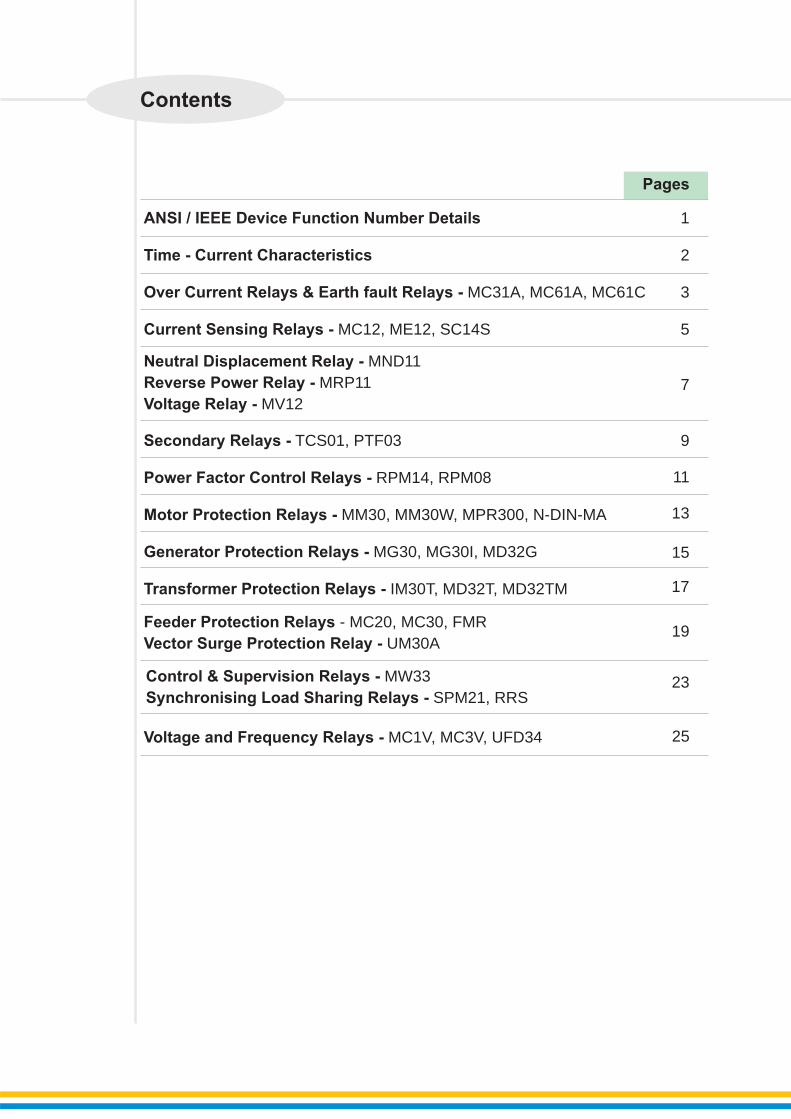
Control & Supervision Relays - MW33
Synchronising Load Sharing Relays - SPM21, RRS
ANSI / IEEE Device Function Number Details
Time - Current Characteristics
Over Current Relays & Earth fault Relays - MC31A, MC61A, MC61C
Current Sensing Relays - MC12, ME12, SC14S
Secondary Relays - TCS01, PTF03
Power Factor Control Relays - RPM14, RPM08
Motor Protection Relays - MM30, MM30W, MPR300, N-DIN-MA
Generator Protection Relays - MG30, MG30I, MD32G
Transformer Protection Relays - IM30T, MD32T, MD32TM
Voltage and Frequency Relays - MC1V, MC3V, UFD34
Feeder Protection Relays - MC20, MC30, FMR
Vector Surge Protection Relay - UM30A
Neutral Displacement Relay - MND11
Reverse Power Relay - MRP11
Voltage Relay - MV12
Contents
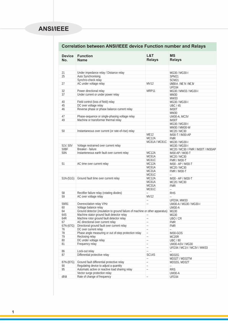
Correlation between ANSI/IEEE device Function number and Relays
Function Name
Device No.
L&T Relays
MS Relays
Under impedance relay / Distance relay Auto Synchronising Synchro-check relayAC under voltage relay
Power directional relayUnder current or under power relay
Field control (loss of field) relayDC over voltage relayReverse phase or phase balance current relay
Phase-sequence or single-phasing voltage relayMachine or transformer thermal relay
Instantaneous over current (or rate-of-rise) relay
Voltage restrained over current relayBreaker - failure Instanteneous earth fault over current relay
AC time over current relay
Ground fault time over current relay
Rectifier failure relay (rotating diodes)AC over voltage relay
Overexcitation relay V/HzVoltage balance relayGround detector (insulation to ground failure of machine or other apparatus)Machine stator ground fault detector relayMachine rotor ground fault detector relayAC directional over current relayDirectional ground fault over current relayDC over current relayPhase angle measuring or out of-step protection relayReclosing relayDC under voltage relayFrequency relay
Lock-out relayDifferential protective relay
Ground fault differential protective relayRegulating device to adjust a quantityAutomatic active or reactive load sharing relay Vector surge protection relay Rate of change of frequency
MV12
MRP11
ME12MC12AMC61A / MC61C
MC12AMC61AMC61CMC12AMC61AMC31AMC61CMC12AMC61AMC31AMC61C–MV12----
--------––----–----SC14S--–––
–
MG30 / MG30-ISPM21SCM21UM30-A / MC1V / MC3VUFD34MG30 / MW33 / MG30-IMM30MW33MG30 / MG30-IUBC / 45IM30TMM30UM30-A, MC3VIM30TMG30 / MG30-IMM30 / MM30-WMC20 / MC30IM30-T / IM30-APFMRMG30 / MG30-I MG30 / MG30-IMC20 / MC30 / FMR / IM30T / IM30APIM30 AP / IM30-TMC20 / MC30FMR / IM30-TIM30 - AP / IM30-TMC20 / MC30FMR / IM30-T--IM30 - AP / IM30-TMC20 / MC30FMR--RHS--UFD34, MW33UM30-A / MG30 / MG30-IUM30-AMG30MG30UBO / CRFMRFMR–IM30-GOS MC20RUBC / 80UM30-ASV / MG30 UFD34 / MC1V / MC3V / MW33--MD32GMD32T / MD32TMMD32G, MD32T--RRSUM30-AUFD34
2125 27 3237 404546 4749
50
51V, 50V50BF 50N
51
51N-(51G)
5859 59/81 606464S64R6767N-(67G)7678798081 8687
87N-(87G)9095
df/dt
1
ANSI/IEEE

2
Time - Current Characteristics (At TMS = 1)
A : Normal Inverse 3.0 Sec. B : Normal Inverse 1.3 Sec. C : Very InverseD : Extreme Inverse
For Trip time at TMS other than 1Trip time = (Trip time at TMS = 1) x TMS OR 50msec whichever is more
Product design standards
Reference standardsIEC 60255, IEC 61000, IS3231, IS8686
Dielectric test : IS 3231 / IEC 60255-5 Impulse test : IS 8686 / IEC 60255- 5 HF disturbance test : IS 8686 / IEC 60255-22-1 Electrostatic discharge test : IEC 61000-4-2Electrical fast transient : IEC 61000-4-4Radiated electro magnetic field test : IEC 61000-4-3Surge immunity : IEC 61000-4-5Ring wave test : IEC 61000-4-12Voltage dips & interruption test : IEC 61000-4-11Power frequency magnetic test : IEC 61000-4-8
Multiple of set current (Is)
Tri
p T
ime
(S
ec
.)
A
B
C
D
1,000
100
10
1
01
1 10 20
Time - Current Characteristics

Salient Features • Display of currents, settings, Trip data & Trip history for analysis & trouble shooting
• Built in self supervision & self testing feature to ensure continuous reliability
• Separate indication for power ON & programming mode on relay fault
• Separate fault indication
• In MC61C - Communication with computer & breaker control through RS485 Port
• Four user programmable output relays
Over Current and Earth Fault Relays• Three Phase Over Current & Earth fault Relays
Description
Device CodeDesignFunctions Available
Settings
Other Features
Burden on CTBurden on PTOperating tempWeightBurden on Auxiliary supplyOutput ContactConstructionDim W x H x D in mmPanel Cut Out
Auxiliary supply Type 1 Type 2CT rating
Output Contacts
3 Phase O/C + E/F
0C
51 RYBNNumerical RelayLowset O/C -IsLowset E/F -Os
O/C Is = 20-200% Step 5% E/F Os = 5-80% Step 5% Time Characteristics available -NI, VI, EI, Definite TimeTMS 0.1 - 1.6 Step 0.05
Site selectable Trip time Char.
Display of Currents, Trip count Self supervision feature
≤ 0.25 VA on CT/PhaseNot applicable
00 to 60 C < 2kg≤ 10 VA1 N/O Contact for self suprvnDraw out121 x 158 x 224113 x 142
20-110 V AC / DC or88-264 V AC / DC1 A or 5 A (site selectable)4 NO or 2 NO + 2 NC
3 Phase O/C + E/F + Highset
0 0C
50/51 RYBNNumerical RelayLowset O/C -IsHighset O/C -IhsLowset E/F -OsHighset E/F -OhsO/C Is = 20-200% Step 5% E/F Os = 5-80% Step 5% HS O/C = (0.2 to 40) x In step of -0.2 In or disableHS E/F = (0.1 to 20) x On step of -0.1 On or disableTime Characteristics available -NI, VI, EI, Definite Time TMS : 0.1 - 1.6 Step 0.05Site selectable Trip time Char.
Highset can be disabledDisplay of Currents, Trip count Self supervision feature
≤ 0.25 VA on CT/PhaseNot applicable0 to 60 C < 2kg≤ 10 VA1 N/O Contact for self suprvnDraw out121 x 158 x 224113 x 142
20-110 V AC / DC or88-264 V AC / DC1 A or 5 A (site selectable)4 NO or 2 NO + 2 NC
3 Phase O/C + E/F + Highset Communication and breaker control
0 0C
50/51 RYBNNumerical RelayLowset O/C -IsHighset O/C -IhsLowset E/F -OsHighset E/F -OhsO/C Is = 20-200% Step 5% E/F Os = 5-80% Step 5% HS O/C = (0.2 to 40) x In step of -0.2 In or disableHS E/F = (0.1 to 20) x On step of -0.1 On or disableTime Characteristics available -NI, VI, EI, Definite TimeTMS : 0.1 - 1.6 Step 0.05HS delay:0.1-2 Sec step 0.01 -Sec. or Inst.RS485 CommunicationBreaker controlAuto doubling of highset, -Relay co-ordination - BI & BO≤ 0.25 VA on CT/PhaseNot applicable0 to 60 C < 2kg≤ 10 VA1 N/O Contact for self suprvn, 1N/O for trip Draw out121 x 158 x 224113 x 142
20-110 V AC / DC or88-264 V AC / DC1 A or 5 A(not site selectable)4 NO
MC61A MC61C
3
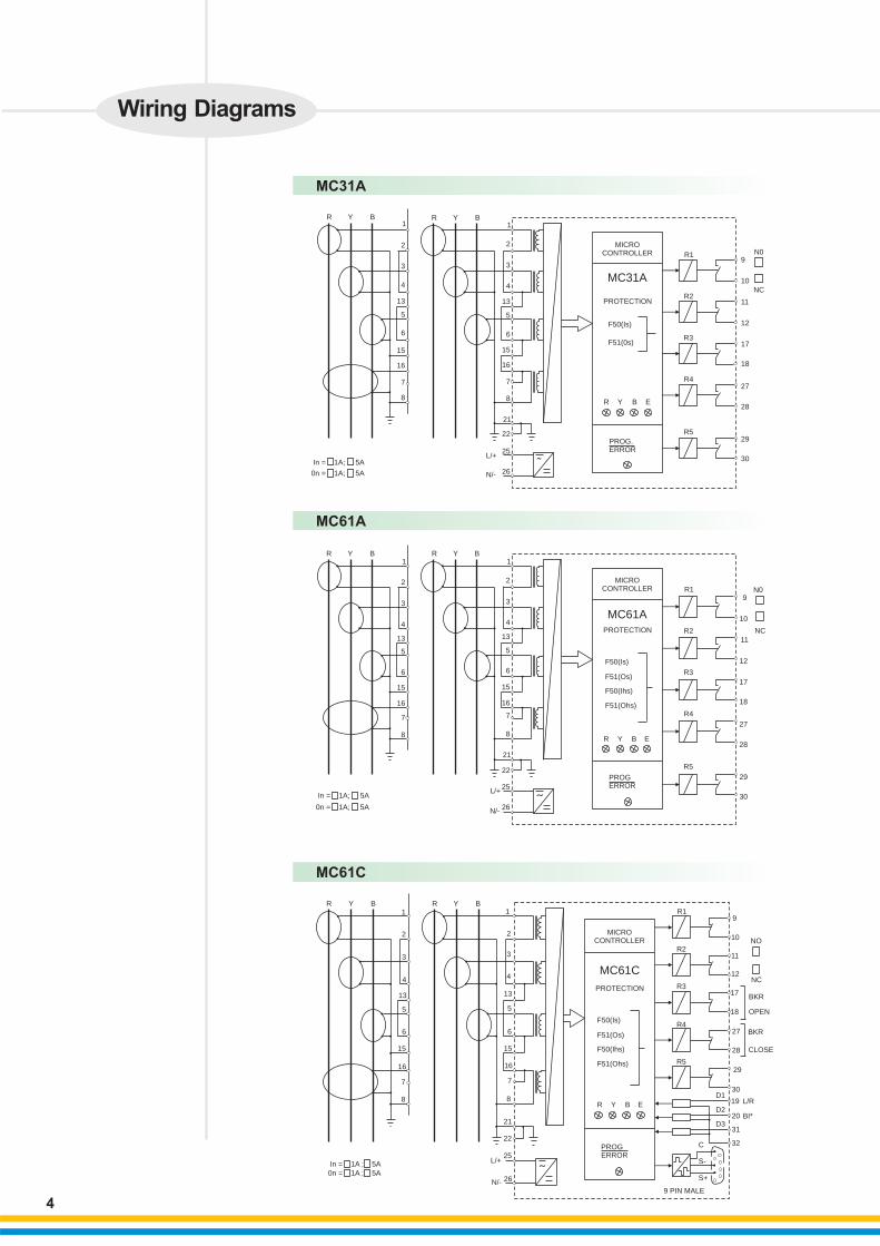
Model MC31A
Ordering Information
MC31A
MC61A
MC61C
MC61A
MC31A
Wiring Diagrams
R Y B R Y B1
2
4
13
5
6
15
16
7
8
3 3
1
2
4
13
5
6
15
16
7
8
22
25
26
21
L/+
N/-
In = 1A; 5A
0n = 1A; 5A
MICRO CONTROLLER
PROTECTION
F50(Is)
F51(0s)
R Y B E
PROGERROR
R1
R2
R3
R4
R5
N0
NC
9
10
11
12
17
18
27
28
29
30˜
R Y B R Y B1
2
4
13
5
6
15
16
7
8
3 3
1
2
4
13
5
6
15
16
7
8
22
25
26
21
In = 1A; 5A
0n = 1A; 5A
L/+
N/-
MICRO CONTROLLER
PROTECTION
F50(Is)
F51(Os)
F50(Ihs)
F51(Ohs)
R Y B E
R1
R2
R3
R4
R5
N0
NC
9
10
11
12
17
18
27
28
29
30
In = 1A ; 5A0n = 1A ; 5A
R Y B R Y B1
2
4
13
5
6
15
16
7
8
3 3
1
2
4
13
5
6
15
16
7
8
22
25
26
21
L/+
N/-
˜
MICRO CONTROLLER
MC61C
PROTECTION
F50(Is)
F51(Os)
F50(Ihs)
F51(Ohs)
R Y B E
PROGERROR
R1
R2
R3
R4
R5
9
10
11
12
17
18
27
28
29
30
19
20
31
32
NO
NC
BKR
OPEN
CLOSE
BKR
L/R
BI*
C
S-
S+
9 PIN MALE
D1
D2
D3
4
PROG.ERROR

Model SC14S
Salient Features
• Easy setting through front panel DIP switches
• Indication for Power ON and trip status
• Test feature - helps in better maintenance • Compact, light weight helps in reducing panel size & thickness
5
• •
Single Phase Over current / Earth fault RelaySensitive E/F Relay / Instantaneous Current Relay
Current Sensing Relays
DescriptionDevice CodeDesignFunctions Available
Settings
Other Features
Burden on CTBurden on PTOperating tempWeightBurden on Auxiliary supplyOutput ContactsConstructionDim W x H x D in mmPanel Cutout
Auxiliary supply Type 1 Type 2CT ratingRange Setting
1 Ph O/C or E/F
≤
0 0C
≤
or
50/51 or 50N/51NMicrocontroller BasedLowset O/C -IsHighset O/C -IhsLowset E/F -OsHighset E/F -IsO/C Is = 50-200% Step 10% ORE/F Is = 10-40% Step 2% ORE/F Is = 20-80% Step 4%HS O/C = (2-16) xls step 2 IsHS E/F = (2-16) xls step 2 IsTime Characteristics available-Nl, VI, EI, Definite Time3 ranges of def Time (1, 10,100)TMS : 0.1 - 1.6 Step 0.1Site selectable Trip time Char.Highset can be disabled
0.25 VA on CT Not applicable 0 - 60 C< 1.5kg
5.5 VA2 C/O Contacts (S/R)Draw out71 x 158 x 22462 x 142
20-110 V AC / DC or88-264 V AC / DC1 A or 5 A10-40% or 20-80% 50-200%Site Selectable
Instantaneous current relay
≤
0 0C
87N/64RStatic
Is = 10-40% step 5%OR 20-80% step 10%
Time Characteristics available-Instantaneous (25ms) OR time delayed 100ms / 200msSelf PoweredRelay testing possible by ext. 24 V -SupplyFlag indication / LED indication
6 VANot Applicable 0 to 60 C< 1.5kgNot Applicable2 C/O Contacts (S/R)Draw out71 x 158 x 22462 x 142
Not Applicable
1 A or 5 A10-40% or 20-80%
1 Ph Sensitive E/F
Time Characteristics available- NI, VI, EI, Definite Time 3 ranges of def Time (1, 10, 100)TMS : 0.1 - 1.6 Step 0.1Site selectable Trip time Char.Highset can be disabledHarmonic rejection≤ 0.25 VA on CTNot applicable
0 00 C to 60 C< 1.5kg≤ 5.5 VA2 C/O Contacts (S/R)Draw out 71 x 158 x 22462 x 142
20-110 V AC / DC or88-264 V AC / DC1 A or 5 A
50N/51NMicrocontroller BasedLowset S E/F -IsHighset S E/F -Ihs.
S E/F = 1-16% step 1%HS S E/F = (2-16) xlsin steps of 2 ls
MC12A ME12A
Ordering Information

MC12A / ME12A
SC14S
6
1
2 +VE/PH.
-VE/NR1
COM
COM
SETTING RANGE (Is)
Aux. Supply
µP. ControlCkt.
F50/50NF51/51N
3
10
11
12
1AIn MC12A
(10-40)% In(20-80)% In(50-200)% In
ME12(1-16)% In
5A
AUX SUPPLY24 - 110V AC/DC95 - 240V AC/DC
MC12A / ME12
Wiring Diagrams
11
10
9
7+
8
12
SC14S
Test (24V)Voltage
DC-DC
Convrt.
Test
ControlCkt.
R
2
1
3
5
6
4
In1A5A
CT OPERATED RELAYNO AUXILIARY SUPPLY REQUIRED
SETTING RANGE (Is)(10-40)% IN(20-80)% IN
˜
Model MND11 MRP11 MV12
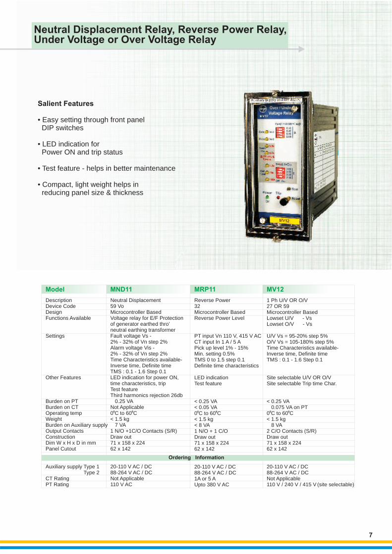
Salient Features
• Easy setting through front panel DIP switches
• LED indication for Power ON and trip status
• Test feature - helps in better maintenance • Compact, light weight helps in reducing panel size & thickness
7
DescriptionDevice CodeDesignFunctions Available
Settings
Other Features
Burden on PTBurden on CTOperating tempWeight Burden on Auxiliary supplyOutput ContactsConstructionDim W x H x D in mmPanel Cutout
Auxiliary supply Type 1 Type 2CT RatingPT Rating
Neutral Displacement59 Vo
0 0C
Microcontroller BasedVoltage relay for E/F Protectionof generator earthed thro’neutral earthing transformerFault voltage Vs -2% - 32% of Vn step 2%Alarm voltage Vis -2% - 32% of Vn step 2%Time Characteristics available- Inverse time, Definite time TMS : 0.1 - 1.6 Step 0.1LED indication for power ON, time characteristics, tripTest featureThird harmonics rejection 26db ≤ 0.25 VA Not Applicable0 to 60 C< 1.5 kg≤ 7 VA1 N/O +1C/O Contacts (S/R)Draw out71 x 158 x 22462 x 142
20-110 V AC / DC88-264 V AC / DCNot Applicable110 V AC
Microcontroller BasedLowset U/V - VsLowset O/V - Vs
U/V Vs = 95-20% step 5%O/V Vs = 105-180% step 5%Time Characteristics available- Inverse time, Definite time TMS : 0.1 - 1.6 Step 0.1
Site selectable U/V OR O/VSite selectable Trip time Char.
≤ 0.075 VA on PT0 to 60 C< 1.5 kg≤ 8 VA2 C/O Contacts (S/R)Draw out71 x 158 x 22462 x 142
20-110 V AC / DC88-264 V AC / DCNot Applicable110 V / 240 V / 415 V (site selectable)
1 Ph U/V OR O/V27 OR 59
< 0.25 VA
0 0C
Microcontroller BasedReverse Power Level
PT input Vn 110 V, 415 V ACCT input In 1 A / 5 APick up level 1% - 15%Min. setting 0.5%TMS 0 to 1.5 step 0.1Definite time characteristics
LED indicationTest feature
< 0.25 VA < 0.05 VA0 to 60 C< 1.5 kg< 8 VA1 N/O + 1 C/ODraw out71 x 158 x 22462 x 142
20-110 V AC / DC88-264 V AC / DC1A 5 AUpto 380 V AC
Reverse Power32
0 0C
or
Neutral Displacement Relay, Reverse Power Relay,Under Voltage or Over Voltage Relay
Ordering Information
MV12
MRP11
MND11
8
µP.Control
Ckt.F64
R Y
14
5
7
8
6
11
µP.
Control
Ckt.
F32
R1
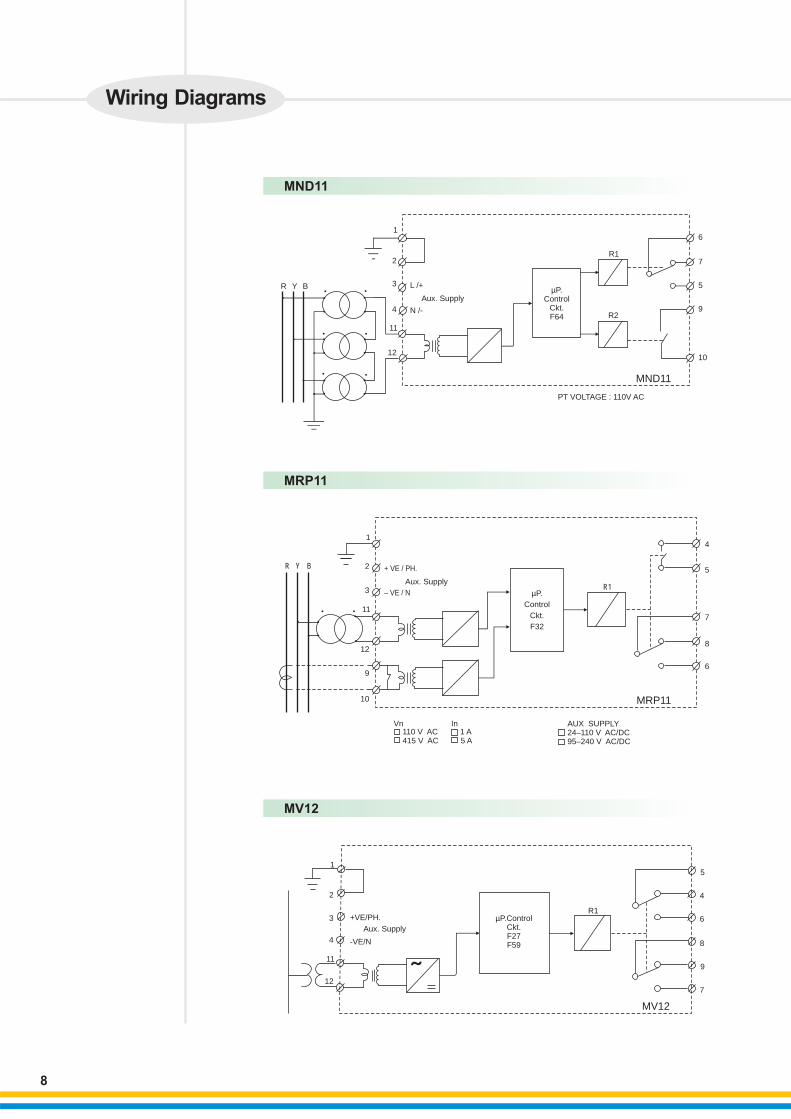
Vn110 V AC 1 A415 V AC 5 A
In AUX SUPPLY24–110 V AC/DC95–240 V AC/DC
MRP11
12
2 + VE / PH.
– VE / N
Aux. Supply3
9
10
B
Wiring Diagrams
5
4
6
8
9
7
R1µP.Control
Ckt.F27F59
1
2
3
11
12
MV12
+VE/PH.
Aux. Supply
-VE/N
R Y B
1
2
3
4
11
12
L /+
Aux. Supply
N /-
MND11
R1
R2
PT VOLTAGE : 110V AC
6
7
5
9
10
4
Model TCS 01
Secondary Relays
9
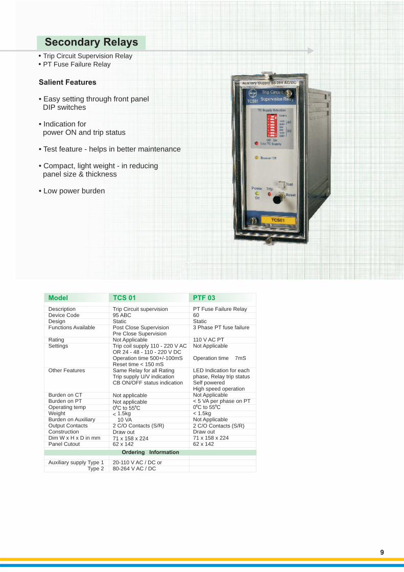
Salient Features
• Easy setting through front panel DIP switches
• Indication for power ON and trip status
• Test feature - helps in better maintenance • Compact, light weight - in reducing panel size & thickness
• Low power burden
• •
Trip Circuit Supervision RelayPT Fuse Failure Relay
Trip Circuit supervision95 ABCStaticPost Close SupervisionPre Close SupervisionNot ApplicableTrip coil supply 110 - 220 V ACOR 24 - 48 - 110 - 220 V DCOperation time 500+/-100mSReset time < 150 mSSame Relay for all RatingTrip supply U/V indicationCB ON/OFF status indication
Not applicable Not applicable
0 00 C to 55 C1.5kg< ≤10 VA 2 C/O Contacts (S/R)Draw out71 x 158 x 22462 x 142
20-110 V AC / DC or80-264 V AC / DC
PT Fuse Failure Relay
0
60Static3 Phase PT fuse failure
110 V AC PT Not Applicable
Operation time ≤ 7mS
LED Indication for each phase, Relay trip statusSelf poweredHigh speed operationNot Applicable< 5 VA per phase on PT
00 C to 55 C< 1.5kgNot Applicable2 C/O Contacts (S/R)Draw out71 x 158 x 22462 x 142
DescriptionDevice CodeDesignFunctions Available
RatingSettings
Other Features
Burden on CTBurden on PTOperating tempWeight Burden on AuxiliaryOutput ContactsConstructionDim W x H x D in mmPanel Cutout
Auxiliary supply Type 1 Type 2
PTF 03
Ordering Information
TCS 01
PTF 03
10
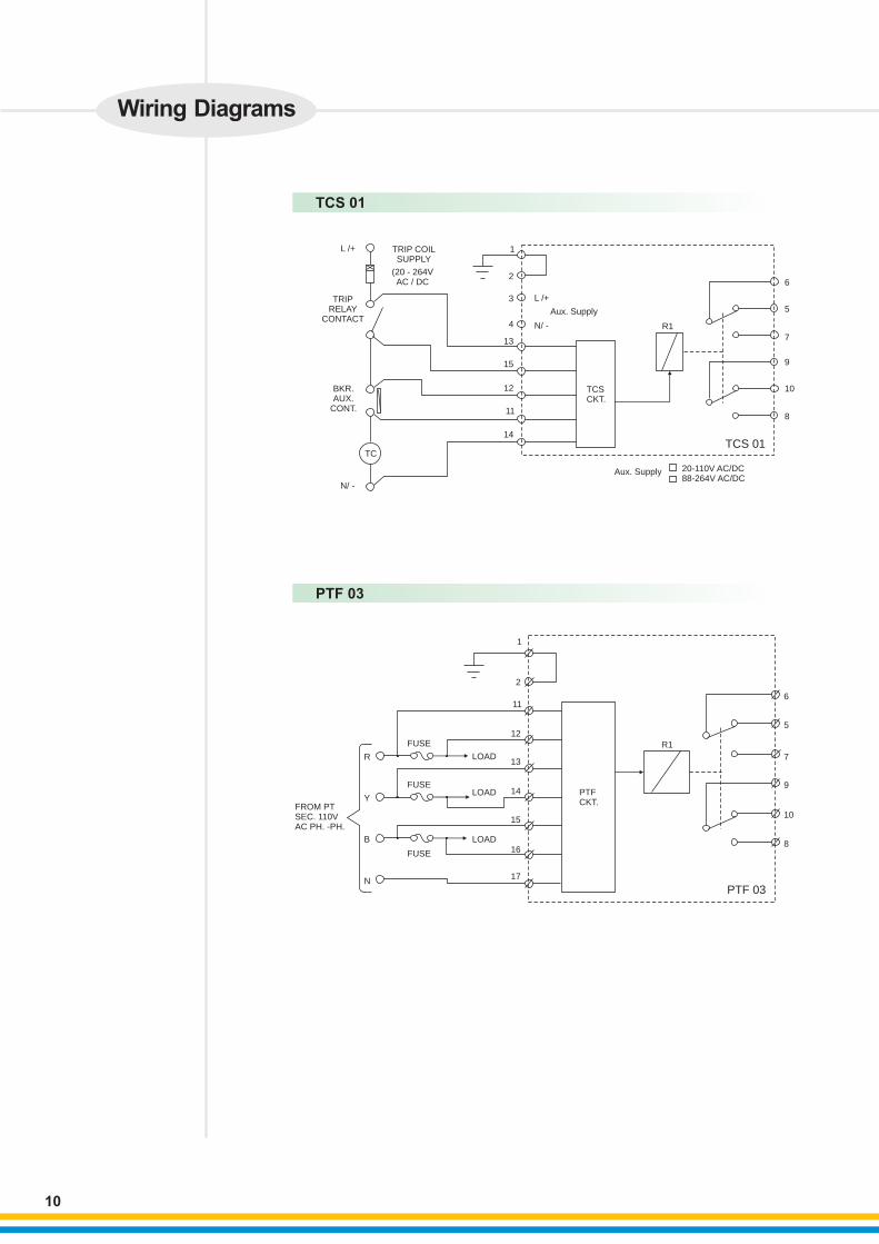
Wiring Diagrams
L /+
TRIPRELAY
CONTACT
TRIP COILSUPPLY
(20 - 264VAC / DC
BKR.AUX.
CONT.
TC
N/ -
1
2
3
4
13
15
12
11
14
L /+
N/ -
Aux. Supply
TCSCKT.
R1
TCS 01
Aux. Supply 20-110V AC/DC88-264V AC/DC
6
5
7
9
10
8
FROM PTSEC. 110VAC PH. -PH.
R
Y
B
N
FUSE
FUSE
FUSE
LOAD
LOAD
LOAD
1
2
11
12
13
14
15
16
17
PTFCKT.
R1
PTF 03
6
5
7
9
10
8
RPM-8Model
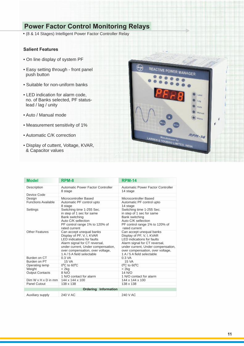
• (8 & 14 Stages) Intelligent Power Factor Controller Relay
Salient Features
•
•
•
• On line display of system PF
• Easy setting through - front panel push button
Suitable for non-uniform banks
• LED indication for alarm code, no. of Banks selected, PF status- lead / lag / unity
Auto / Manual mode
Measurement sensitivity of 1%
• Automatic C/K correction
• Display of cuttent, Voltage, KVAR, & Capacitor values
11
Power Factor Control Monitoring Relays
Description
Device CodeDesignFunctions Available
Settings
Other Features
Burden on CTBurden on PTOperating tempWeightOutput Contacts
Dim W x H x D in mmPanel Cutout
Auxiliary supply
Automatic
Microcontroller BasedAutomatic PF control upto8 stageSwitching time 1-255 Sec.in step of 1 sec for sameBank switchingAuto C/K sellectionPF control range 1% to 120% ofrated current Can accept unequal banksDisplay of PF, V, l, KVARLED indications for faultsAlarm signal for CT reversal, under current, Under compensation, over compensation, over voltage,1 A / 5 A field selectable0.3 VA≤ 15 VA
00 to 60 C< 2kg8 N/O1 N/O contact for alarm144 x 144 x 100138 x 138
240 V AC
Power Factor Controller8 stage
0C
RPM-14 Automatic
Microcontroller BasedAutomatic PF control upto14 stageSwitching time 1-255 Sec.in step of 1 sec for sameBank switchingAuto C/K sellectionPF control range 1% to 120% of rated current Can accept unequal banksDisplay of PF, V, l, KVARLED indications for faultsAlarm signal for CT reversal, under current, Under compensation, over compensation, over voltage,1 A / 5 A field selectable0.3 VA≤ 15 VA
00 to 60 C< 2kg14 N/O1 N/O contact for alarm144 x 144 x 100138 x 138
240 V AC
Power Factor Controller14 stage
0C
Ordering Information
12
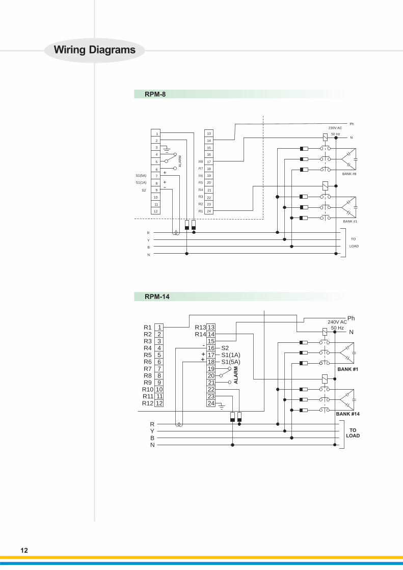
Wiring Diagrams
RPM-8
RPM-14
123456789101112
R1R2R3R4R5R6R7R8R9R10R11R12
131415161718192021222324
R13R14
-
++
RYBN
S2S1(1A)S1(5A)
AL
AR
M
Ph240V AC
50 HzN
BANK #1
BANK #14
TOLOAD
1
2
3
4
5
6
7
8
9
10
11
12
S1(5A)
S1(1A)
S2
AL
AR
M
+
+-
R
Y
B
N
R8
R7
R6
R5
R4
R3
R2
R1
13
14
15
16
17
18
19
20
21
22
23
24
Ph230V AC
50 HzN
BANK #8
TO
LOAD
BANK #1
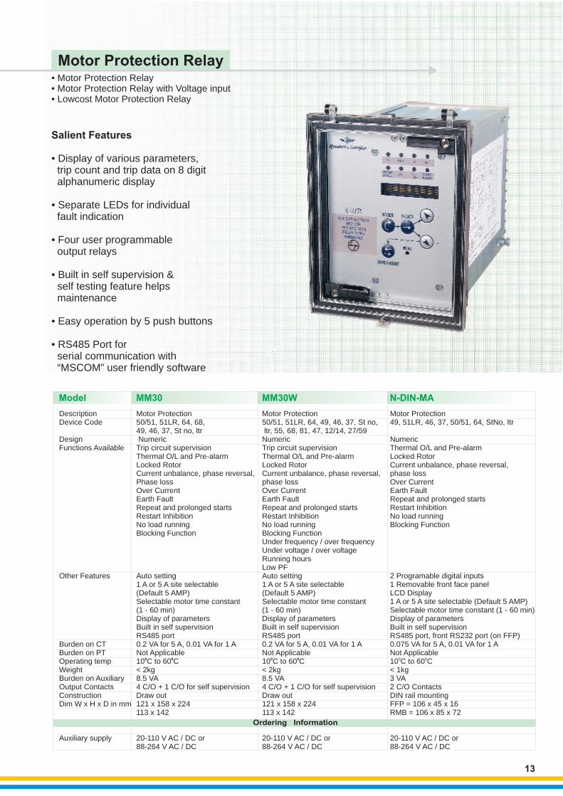
• Motor Protection Relay• Motor Protection Relay with Voltage input• Lowcost Motor Protection Relay
Motor Protection Relay
Salient Features
• Display of various parameters, trip count and trip data on 8 digit alphanumeric display
• Separate LEDs for individual fault indication
• Four user programmable output relays
• Built in self supervision & self testing feature helps maintenance
• Easy operation by 5 push buttons
• RS485 Port for serial communication with “MSCOM” user friendly software
13
DescriptionDevice Code
DesignFunctions Available
Other Features
Burden on CTBurden on PTOperating tempWeightBurden on AuxiliaryOutput ContactsConstructionDim W x H x D in mm
Auxiliary supply
Motor Protection50/51, 51LR, 64, 68, 49, 46, 37, St no, ltr
0 0
NumericTrip circuit supervision Thermal O/L and Pre-alarmLocked RotorCurrent unbalance, phase reversal, Phase lossOver CurrentEarth FaultRepeat and prolonged startsRestart InhibitionNo load runningBlocking Function
Auto setting1 A or 5 A site selectable(Default 5 AMP)Selectable motor time constant (1 - 60 min)Display of parametersBuilt in self supervisionRS485 port0.2 VA for 5 A, 0.01 VA for 1 ANot Applicable 10 C to 60 C< 2kg8.5 VA4 C/O + 1 C/O for self supervisionDraw out121 x 158 x 224113 x 142
20-110 V AC / DC or88-264 V AC / DC
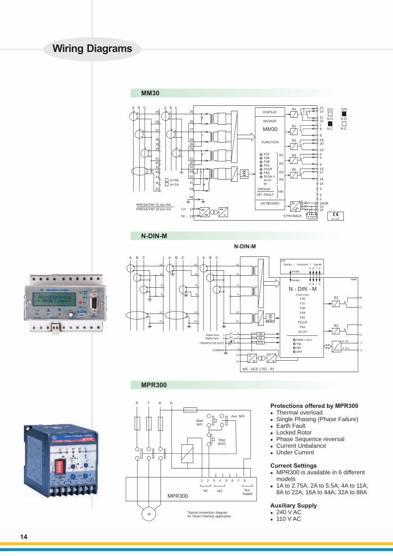
Model MM30
Motor Protection
0 0C
49, 51LR, 46, 37, 50/51, 64, StNo, Itr
NumericThermal O/L and Pre-alarmLocked RotorCurrent unbalance, phase reversal, phase lossOver CurrentEarth FaultRepeat and prolonged startsRestart InhibitionNo load runningBlocking Function
2 Programable digital inputs1 Removable front face panelLCD Display1 A or 5 A site selectable (Default 5 AMP)Selectable motor time constant (1 - 60 min)Display of parametersBuilt in self supervisionRS485 port, front RS232 port (on FFP)0.075 VA for 5 A, 0.01 VA for 1 ANot Applicable 10 to 60 C< 1kg3 VA2 C/O ContactsDIN rail mountingFFP = 106 x 45 x 16RMB = 106 x 85 x 72
20-110 V AC / DC or88-264 V AC / DC
N-DIN-MA
Motor Protection50/51, 51LR, 64, 49, 46, 37, St no, ltr, 55, 68, 81, 47, 12/14, 27/59
0 0
NumericTrip circuit supervision Thermal O/L and Pre-alarmLocked RotorCurrent unbalance, phase reversal, phase lossOver CurrentEarth FaultRepeat and prolonged startsRestart InhibitionNo load runningBlocking FunctionUnder frequency / over frequency Under voltage / over voltage Running hours Low PF Auto setting1 A or 5 A site selectable (Default 5 AMP)Selectable motor time constant (1 - 60 min)Display of parametersBuilt in self supervisionRS485 port0.2 VA for 5 A, 0.01 VA for 1 ANot Applicable 10 C to 60 C< 2kg8.5 VA4 C/O + 1 C/O for self supervisionDraw out121 x 158 x 224113 x 142
20-110 V AC / DC or88-264 V AC / DC
MM30W
Ordering Information
MM30
N-DIN-M
14
L/+
N/-
MPR300
R Y B
StartN/O
Stop (N/C)
Aux. Supply
Typical connection diagramfor 'Direct Starting' application
MPR300
M
NC NO
1 2 3 4 5 6 7 8
Aux. N/O
N
Wiring Diagrams
A B C A B C25
26
27
28
29
41
30
32
39
25
26
27
28
39
29
413032
43
31
42
33
43
31
42
33
44
In=1A
In=5A
PRESA/TAP 31:Ion=5A
PRESA/TAP 33:Ion=1A 12
13 ˜˜
˜
˜̃̃
=
DISPLAY
MICROP.
MM30
FUNCTION
F37F46F49F51F51RF64St.No.>AI.0>Itr
PROGR.
INT. FAULT
KEYBOARD
R1
R2
R3
R4
R5
R1
R2
R3
R4
R5
9 PIN MALE
(21) (10)
N.O. N.O.
N.C. N.C.
2110
1122
79
8
1820
1946
5
1517
16
14
3
2
1
34/382324
CS-S+
IEC 255
A B C A B C A B C
10
11
8
9
12
13
10
11
8
9
12
13
10
11
8
9
12
13
6
7
2
1
21
22
0C
T
TDigital Input 1
Digital Input 2
THERMISTOR INPUT
COMMON
BT 2 1
D1
D2
RTD
MS - SCE 1752 - R1
FFP
Display / Keyboard / Signals
RS485
RS485
A B + 0
A B + 0
N - DIN - MFUNCTIONS
F26
F37
F46
F49
F51
F51LR
F64
St.Ctrl
PWR / I.R.F
Trip
ON
OFF
R1
RMB
R2
B (S-)
A (S+)RS485
16
17
15
14
4
5
N-DIN-M
Protections offered by MPR300 lThermal overload
Single Phasing (Phase Failure)Earth FaultLocked RotorPhase Sequence reversalCurrent UnbalanceUnder Current
l
l
l
l
l
l
Current Settings lMPR300 is available in 6 different models l1A to 2.75A; 2A to 5.5A; 4A to 11A; 8A to 22A; 16A to 44A; 32A to 88A
Auxiliary Supplyl240 V AC l110 V AC
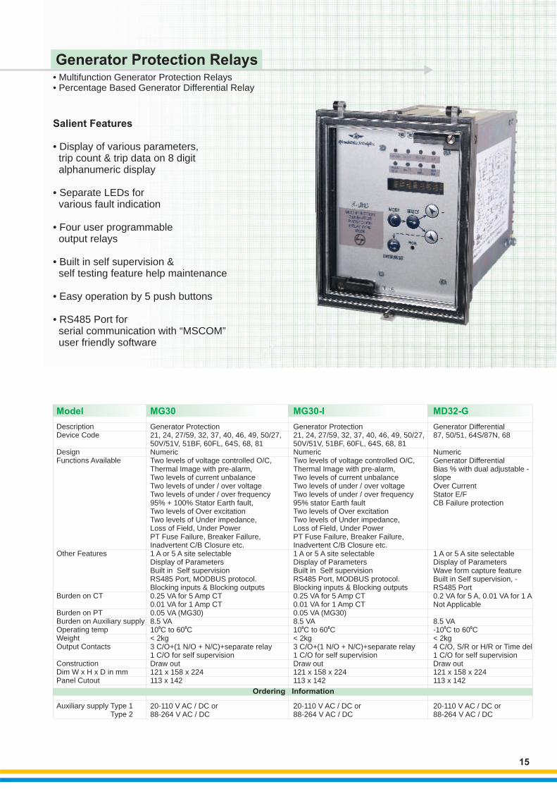
• Multifunction Generator Protection Relays• Percentage Based Generator Differential Relay
Generator Protection Relays
Salient Features
• Display of various parameters, trip count & trip data on 8 digit alphanumeric display
• Separate LEDs for various fault indication
• Four user programmable output relays
• Built in self supervision & self testing feature help maintenance
• Easy operation by 5 push buttons
• RS485 Port for serial communication with “MSCOM” user friendly software
15
DescriptionDevice Code
DesignFunctions Available
Other Features
Burden on CT
Burden on PTBurden on Auxiliary supplyOperating tempWeightOutput Contacts
ConstructionDim W x H x D in mmPanel Cutout
Auxiliary supply Type 1 Type 2
Generator Protection21, 24, 27/59, 32, 37, 40, 46, 49,
0 0C
3 C/O+(1 N/O + N/C)+separate relay1 C/O for self supervision
50/27, 50V/51V, 51BF, 60FL, 64S, 68, 81NumericTwo levels of voltage controlled O/C,Thermal Image with pre-alarm,Two levels of current unbalanceTwo levels of under / over voltageTwo levels of under / over frequency95% + 100% Stator Earth fault, Two levels of Over excitationTwo levels of Under impedance,Loss of Field, Under PowerPT Fuse Failure, Breaker Failure,Inadvertent C/B Closure etc.1 A or 5 A site selectableDisplay of ParametersBuilt in Self supervisionRS485 Port, MODBUS protocol.Blocking inputs & Blocking outputs0.25 VA for 5 Amp CT0.01 VA for 1 Amp CT0.05 VA (MG30)8.5 VA10 to 60 C< 2kg
Draw out121 x 158 x 224113 x 142
20-110 V AC / DC or88-264 V AC / DC
Generator Differential
0 0C
87, 50/51, 64S/87N, 68
NumericGenerator Differential Bias % with dual adjustable -slopeOver Current Stator E/F CB Failure protection
1 A or 5 A site selectableDisplay of ParametersWave form capture feature Built in Self supervision, -RS485 Port0.2 VA for 5 A, 0.01 VA for 1 ANot Applicable
8.5 VA-10 to 60 C< 2kg4 C/O, S/R or H/R or Time del1 C/O for self supervisionDraw out121 x 158 x 224113 x 142
20-110 V AC / DC or88-264 V AC / DC
Model MG30 MD32-G
Generator Protection21, 24, 27/59, 32, 37, 40, 46, 49,
0 0C
3 C/O+(1 N/O + N/C)+separate relay1 C/O for self supervision
50/27, 50V/51V, 51BF, 60FL, 64S, 68, 81NumericTwo levels of voltage controlled O/C,Thermal Image with pre-alarm,Two levels of current unbalanceTwo levels of under / over voltageTwo levels of under / over frequency95% stator Earth faultTwo levels of Over excitationTwo levels of Under impedance,Loss of Field, Under PowerPT Fuse Failure, Breaker Failure,Inadvertent C/B Closure etc.1 A or 5 A site selectableDisplay of ParametersBuilt in Self supervisionRS485 Port, MODBUS protocol.Blocking inputs & Blocking outputs0.25 VA for 5 Amp CT0.01 VA for 1 Amp CT0.05 VA (MG30)8.5 VA10 to 60 C< 2kg
Draw out121 x 158 x 224113 x 142
20-110 V AC / DC or88-264 V AC / DC
MG30-I
Ordering Information
16
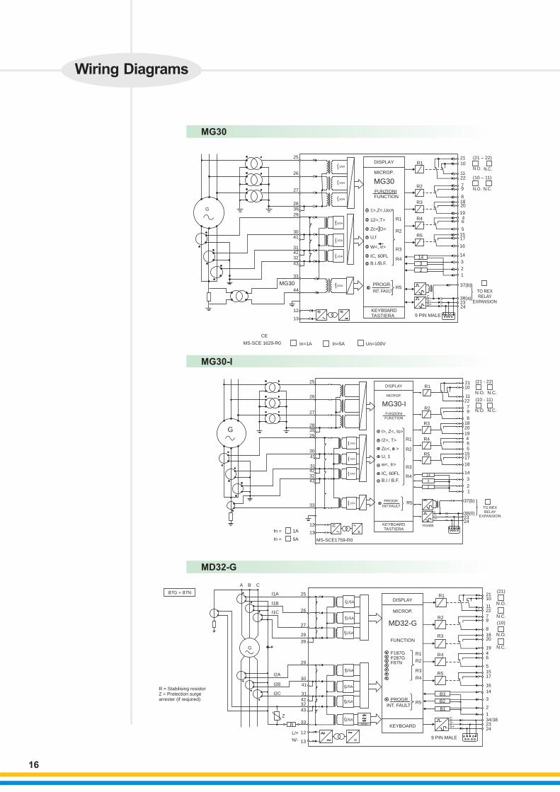
MG30
Wiring Diagrams
25
26
27
283929
3041
31423243
33
44
12
13
G
1/5A
1/5A
1/5A
1/5A
1/5A
1/5A
1/5A
DISPLAY
MICROP.
R1
R2
R3
R4
R5
14
3
2
2110
1122
79
81820
1946
51517
16
14
3
2
1
FUNZIONI
1>,Z<,Uo>
R1
R2
R3
R4
R5
12>,T>
Zc<,O>
U,f
W<, Ir>
IC, 60FL
B.I./B.F.
PROGR.
INT. FAULT
KEYB0ARDTASTIERA
FUNCTION
MG30
38(a)
37(b)
TO REXRELAY
EXPANSION2324
9 PIN MALE
S–S+
C
(21 – 22)
(10 – 11)
N.O.
N.O.
N.C.
N.C.
CE
MS-SCE 1629-R0 In=1A In=5A Un=100V
MG30
MD32-G
R = Stabilising resistorZ = Protection surge arrester (if required)
L/+
N/-
DISPLAY
MICROP.
MD32-G
FUNCTION
F187GF287GF87N
87G + 87N
A B C
I1A
I1B
I1C
G
25
26
27
28
39
29
30
41
31423243
33
13
12
I2A
I2B
I2C
Z
R KEYBOARD
PROGR.
INT. FAULT
=˜˜
˜_
˜̃̃50-60
R5
R4
R3
R2
R1
R3
R2
R1
R4
R5
B3
B2
B1
9 PIN MALE
242334/381
2
3
14
16
17155
6419
2018
8
972211
1021
(21)
N.O.
N.C.
(10)
N.O.
N.C.
CS-S+
1/5A
1/5A
1/5A
1/5A
1/5A
1/5A
1/5A
MG30-I
G
In =
In =
13
12
33
43324231
4130
293928
27
26
25
1A
5A MS-SCE1759-R0
DISPLAY
MICROP.
MG30-IFUNZIONI
FUNCTION
I>, Z<, Io>
I2>, T>
IC, 60FL
B.I / B.F.
PROGR.
INT.FAULT
KEYBOARDTASTIERA
R1
R2
R3
R4
R5
R1
R2
R3
R4
R5
14
3
2
RS485
2110
1122
79
8182019465
1517
18
14
3
21
37(b)
38(0)2324
TO REXRELAY
EXPANSION
(21 - 22)
N.O. N.C.
(10 - 11)
N.O. N.C.
1/5A
1/5A
1/5A
1/5A
Zc<, >
U, 1
w< Ir>+
cs-s+
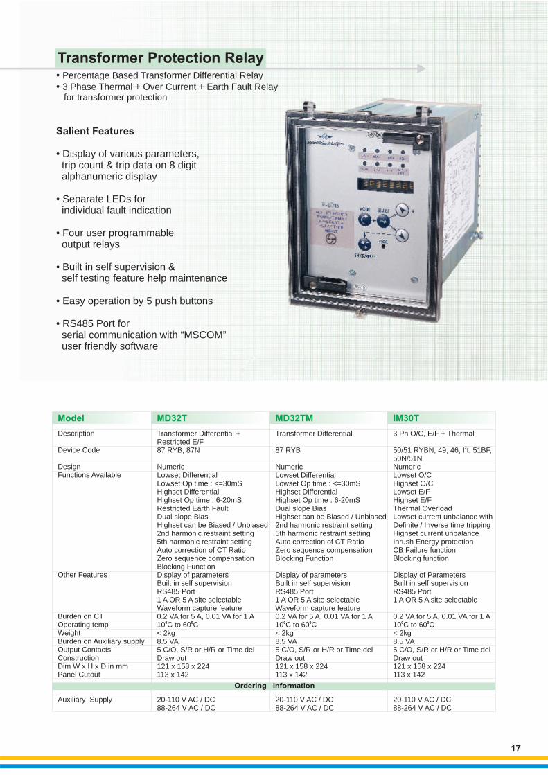
3 Phase Thermal + Over Current + Earth Fault Relay for transformer protection
• •
Percentage Based Transformer Differential Relay
Transformer Protection Relay
Salient Features
• Display of various parameters, trip count & trip data on 8 digit alphanumeric display
• Separate LEDs for individual fault indication
• Four user programmable output relays
• Built in self supervision & self testing feature help maintenance
• Easy operation by 5 push buttons
• RS485 Port for serial communication with “MSCOM” user friendly software
17
Description
Device Code
DesignFunctions Available
Other Features
Burden on CTOperating tempWeightBurden on Auxiliary supplyOutput ContactsConstructionDim W x H x D in mmPanel Cutout
Auxiliary Supply
3 Ph O/C, E/F + Thermal
0 0C
88-264 V AC / DC
250/51 RYBN, 49, 46, I t, 51BF, 50N/51NNumericLowset O/C Highset O/CLowset E/FHighset E/FThermal Overload Lowset current unbalance withDefinite / Inverse time trippingHighset current unbalanceInrush Energy protectionCB Failure functionBlocking function
Display of ParametersBuilt in self supervisionRS485 Port 1 A OR 5 A site selectable
0.2 VA for 5 A, 0.01 VA for 1 A10 to 60 C< 2kg8.5 VA5 C/O, S/R or H/R or Time delDraw out121 x 158 x 224113 x 142
20-110 V AC / DC
Transformer Differential + Restricted E/F
0 0C
87 RYB, 87N
NumericLowset DifferentialLowset Op time : <=30mSHighset DifferentialHighset Op time : 6-20mSRestricted Earth FaultDual slope BiasHighset can be Biased / Unbiased2nd harmonic restraint setting5th harmonic restraint settingAuto correction of CT RatioZero sequence compensationBlocking FunctionDisplay of parametersBuilt in self supervisionRS485 Port1 A OR 5 A site selectableWaveform capture feature0.2 VA for 5 A, 0.01 VA for 1 A10 to 60 C< 2kg8.5 VA5 C/O, S/R or H/R or Time delDraw out121 x 158 x 224113 x 142
20-110 V AC / DC88-264 V AC / DC
Transformer Differential
0 0C
87 RYB
NumericLowset DifferentialLowset Op time : <=30mSHighset DifferentialHighset Op time : 6-20mSDual slope BiasHighset can be Biased / Unbiased2nd harmonic restraint setting5th harmonic restraint settingAuto correction of CT RatioZero sequence compensationBlocking Function
Display of parametersBuilt in self supervisionRS485 Port1 A OR 5 A site selectableWaveform capture feature0.2 VA for 5 A, 0.01 VA for 1 A10 to 60 C< 2kg8.5 VA5 C/O, S/R or H/R or Time delDraw out121 x 158 x 224113 x 142
20-110 V AC / DC88-264 V AC / DC
Model MD32T MD32TM IM30T
Ordering Information
18
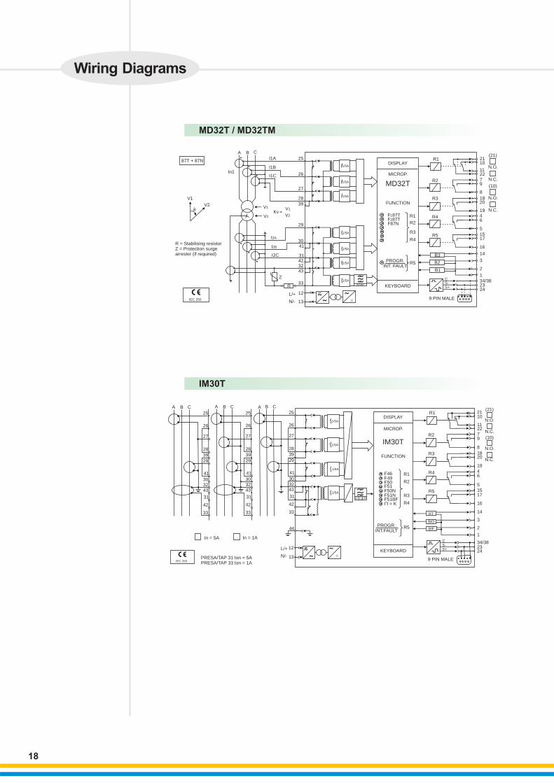
MD32T / MD32TM
MD32T
R = Stabilising resistorZ = Protection surgearrester (if required)
L/+
N/-
Wiring Diagrams
˜
IEC 255 ˜˜
=
˜̃
˜
87T + 87N
A B C
In1
I1A
I1B
I1C
25
26
27
2839
V1
V2
Kv =V1
V2
29
I2A
I2B
I2C
3041
31423243
Z
33
12
13
R 50-60
1/5A
1/5A
1/5A
1/5A
KEYBOARD
PROGR.INT. FAULT
R5
R4
R3
R2
R1F187TF287TF87N
FUNCTION
MICROP.
DISPLAYR1
R2
R3
R4
R5
B3
B2
B1
9 PIN MALE
CS-S+
242334/381
2
3
14
16
17155
6419
2018
8
972211
1021
(21)
N.O.
N.O.
N.C.
N.C.
(10)
V1
V2á
IM30T
IM30T
L/+
N/-
1/5A
1/5A
1/5A
1/5A
A B C A B C A B C
25
26
27
28
39
29
41
303243
31
42
33
25
26
27
28
39
29
41
303243
31
42
33
25
26
27
28
39
29
41
303243
31
42
33
˜
˜̃˜
˜˜
=
_
44
12
13
In = 5A In = 1A
PRESA/TAP 31 Ion = 5APRESA/TAP 33 Ion = 1A
KEYBOARD
PROGR.INT.FAULT
R5
R4
R3
R2
R1
R3
R4
R5
R2
R1
F46
2I t = KF51BFF51NF50NF51F50F49
FUNCTION
MICROP.
DISPLAY
RT
BIO
BIF
CS-S+
9 PIN MALE
242334/38
1
2
3
14
16
17155
6419
2018
8
972211
1021
(21)
N.O.
N.O.
N.C.
N.C.
(10)
IEC 255
BT 2 50
1/5A
1/5A
1/5A
Model
19
MC30MC20
3P O/C + E/F + Highset + Autoreclosing (Optional)51, 51N, 50, 50N, 51BF, 79 (optional)NumericLowset O/C2 Highset O/C LevelsLowset E/F2 Highset E/F LevelsTime current curves selectable accordingto IEC/IEEE standardsAuto Reclose (In MC20-R)Breaker Failure protectionCircuit Breaker control via serial portBlocking Output and Blocking Input for pilotwire selectivity coordinationTime tagged multiple event recordingOscillographic wave form captureAccepts 3 Digital inputsDisplay LCD 16 (2 x 8) characters3rd Harmonic Filter on the neutral input currentPassword protection facility1 A or 5 A site selectableDisplay of parametersBuilt in supervisionModbus RTU / IEC870-5-103 Communication ProtocolsFront RS232 Port for Local ProgrammingOscillographic recording of input QuantitiesRS485 serial communication port on Back Panel0.1 VA for 1 A, 0.3 VA for 5 ANA< 7 VA
4 C/O ContactsDrawout83 x 164 x 22564 x 137
24-110 V AC/DC 88-264 V AC/DC
0 0-10 C to 55 C<1.5Kg
3P O/C + E/F + Highset 51, 51N, 50, 50N, 49, 51BFNumericLowset O/C2 Highset O/C LevelsLowset E/F2 Highset E/F LevelsThermal imageBreaker Failure protection Circuit Breaker control via Serial port Blocking Output and Blocking Input for pilotWire selectivity coordinationTime tagged multiple event recordingOscillographic wave form captureAccepts 3 Digital inputsDisplay LCD 16 (2 x 8) charactersT
Password protection facility
1 A or 5 A site selectableDisplay of parametersBuilt in supervisionModbus RTU / IEC870-5-103 Communication ProtocolsFront RS232 Port for Local ProgrammingOscillographic recording of input QuantitiesRS485 serial communication port on Back Panel0.1 VA for 1 A, 0.3 VA for 5 ANA< 7 VA
4 C/O ContactsDrawout83 x 164 x 22564 x 137
24-110 V AC/DC 88-264 V AC/DC
ime current curves selectable accordingto IEC/IEEE standards
0 0-10 C to 55 C<1.5Kg
DescriptionDevice CodeDesignFunctions Available
RatingOther Features
Burden on CTBurden on PTBurden on Aux. SupplyOperating TempWeightOutput ContactsConstructionDimPanel Cutout
Aux. Supply Type 1 Type 2
• •
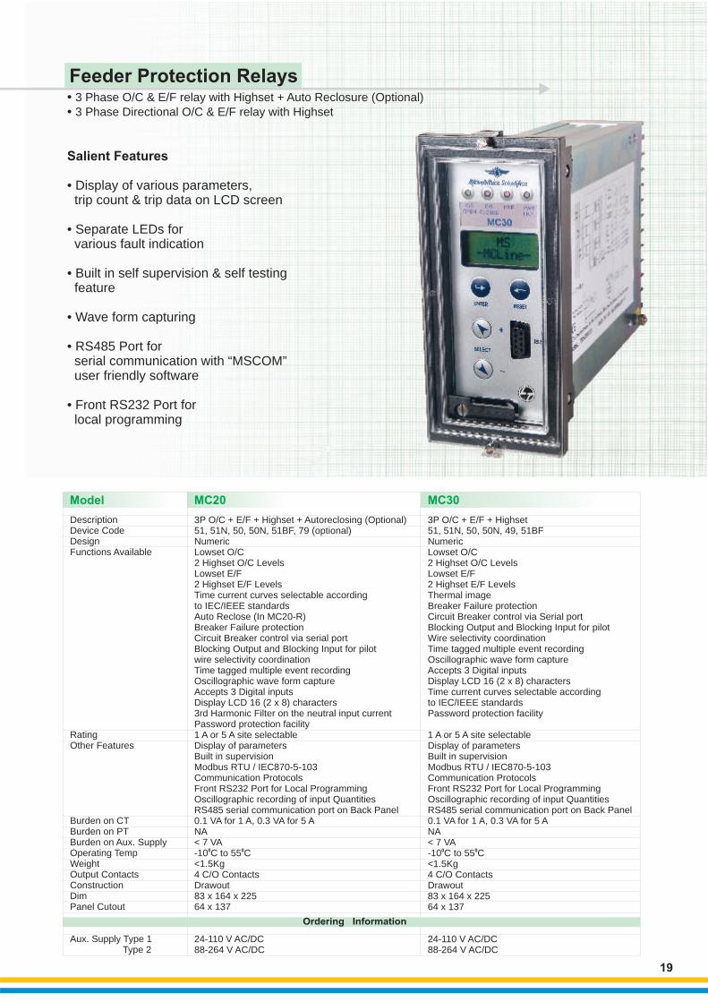
3 Phase O/C & E/F relay with Highset + Auto Reclosure (Optional)3 Phase Directional O/C & E/F relay with Highset
Salient Features
RS485 Port for serial communication with “MSCOM” user friendly software
• Display of various parameters, trip count & trip data on LCD screen
• Separate LEDs for various fault indication
• Built in self supervision & self testing feature
• Wave form capturing •
• Front RS232 Port for local programming
Feeder Protection Relays
Ordering Information

Wiring Diagrams
MC20
20
MC30
1/5A
1/5A
1/5A
1/5A
4
5
6
7
8
9
In=
F50
F51
F50N
F51N
PROGR.INT.FAULT
R1
R2
R3
R4
R1
R2
R3
R4
D3
D2
D1
RS232KEYBOARD TASTIERA
10
11
BPMC
16
18
1714
15
13
12
2021
1922
OUTPUTRELAYS
RELEDI USCITA
DIGITALINPUTS
INCRESSIDIGITAL
321
RS485
MS-SCE1895-R2Standard Output
MS -SCE1924-R2I/O Output
DIGITALINPUTINGRESSDIGITAL
TO I/0 RELAYEXPANSIONALL ESPANSIONEDI I/0COMUNECOMUNE
RS485
R1
R2
R3
D3
D2
D1
OUTPUTRELAYS
RELEDI USCITA
CA (S+)B (S-)
LH
C
A (S+)B (S-)
16
18
1714
15
20
19
21
22
1312
3
21
AUXILIARY SUPPLY
5A1A
DISPLAY
MICROP.
MC30FUNZION
FUNCTIONS
BT 2
MS - SCE 1828 - R1
1/5A
1/5A
1/5A
6
7
4
5
8
9
6
7
4
5
8
9
In = □ 1A □ 5A
lon = □ 1A □ 5A
Auxiliary SupplyAlimentazione Ausiliaria
10
11
BPMC
KEYBOARDTASTIERA
RS232
PROGR.
INT.FAULTR4
R3
R2
R1F50
F51
F50N
F51N
FUNZIONIFUNCTIONS
MC20
MICROP.
DISPLAY
R4
R3
R2
R1
D1
D2
D3
16
18
17
14
15
13
12
20
21
19
22
321
RS485
DIGITALINPUTS
INGRESSIDIGITALI
RELE’DI USCITA
OUTPUTRELAYS
R3
R2
R1 16
18
17
14
15
RELE’DI USCITA
OUTPUTRELAYS
20
21
19
22
1312
3
21
DIGITALINPUTS
INGRESSIDIGITALI
RS485
COMUNECOMUNE
TO I/0 RELAYEXPANSIONALL’ ESPANSIONEDI I/0
MS - SCE 1828 - R1Standard Output
MS - SCE 1839 - R2I/O Output
D3
D1
D2
HL
C
A (S+)
B (S-)
C
A (S+)
B (S+)
50
A B C A B C

21
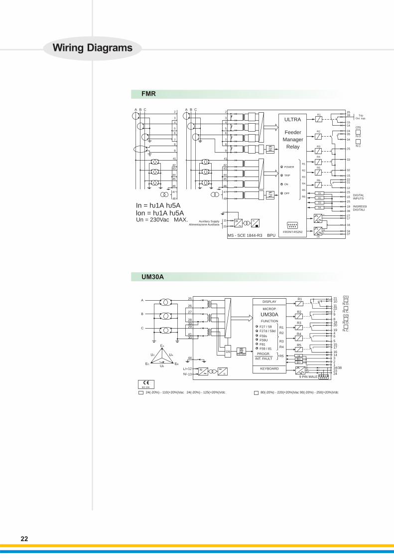
Model FMR
DescriptionDevice CodeDesignFunctions Available
RatingOther Features
Burden on CTBurden on PTBurden on Aux. SupplyOperating TempWeightBurden on Aux.Output ContactsConstructionDimPanel Cutout
Aux. Supply Type 1 Type 2
Feeder Manager Relay246, 49, 50/51, 67, 50N/51N, 67N, 27/59, 59UO, 74, 81, 86, 121, I t
NumericThree levels for phase over current independentlyprogrammable as directional or non directionalThree levels for Earth Fault independently programmableas directional or non directionalThermal imageSelectable Time current curves according to IEC and IEEE standardsTwo over/under voltage levelsTwo over/under frequency levelsZero sequence over voltage levelTwo Negative Sequence current levelsOne Positive Sequence over voltage levelOne Negative Sequence undervoltage levelTrip circuit supervisionAssociated Circuit Breaker controlBreaker failure protectionBreaker interruption energy1 A or 5 A site selectable / 100-125 V PTIGraphical display 128 x 64 dotsDisplay of V, I, PF, kW, kVA, kVAr and thermal statusModbus RTU / IEC870-5 Communication ProtocolsRS232 serial communication port on front faceMIMIC diagram on LCDOscillographic recording of input quantitiesRS485 serial communication port on Back PanelPhase 0.01 VA at In = 1 A; 0.2 VA at In = 5 A Neutral0.01 VA at In = 1A; 0.2 VA at In = 5 A0.1 VA at UN
6 C/O ContactsDrawout121 x 164 x 224113 x 142
20-110 V AC/DC or 88-264 V AC/DC
0 0-10 C to 55 C<2Kg<10 VA
3 Phase Directional O/C & E/F relay with Highset 3 Phase voltage and frequency relay with vector shift
• •
FMR - Salient Features :-
RS485 Port for serial communication with “MSCOM” user friendly software
• Display of various parameters, trip count & trip data on LCD screen
• Separate LEDs for various fault indication
• Built in self supervision & self testing feature
• Wave form capturing •
• Front RS232 Port for local programming
Feeder Protection Relays / Vector Shift Relay
3 Phase V and F relay with vector shift24, 27d/59d, 47, 59, 59Uo, 78, 81
0C
NumericOver FluxingTwo Levels of under / over voltageTwo Levels of under / over frequency.Zero seq. voltageVoltage unbalanceVector shift detection
Display of ParametersBuilt in Self supervisionRS485 Port
NA0.2 VA / Phase at UN8.5 VA
010 to 60 C< 2kg3 C/O+(1 N/O + 1 N/C)+separate relay1 C/O for self supervisionDraw out121 x 158 x 224113 x 142
20-110 V AC / DC or88-264 V AC / DC
UM30A
Ordering Information
FMR
A B C A B C2
3
4
5
6
7
8
9
41
4243
44
45
46
47
48
2
3
4
5
6
7
8
9
41
4243
44
45
46
47
48
ULTRA
Feeder
Manager
Relay
POWER
TRIP
ON
OFF
11
21
R1
R2
R3
R4
R5
R6
R1
R2
R3
R4
R5
R6
D1
D2
D3
D4
+-
HL
ON
2528
15
25
14
2435
34
33
32
15
2231
12
25
15
25
19
38
2717
16
3437
In = □ 1A □ 5A lon = □ 1A □ 5A
MS - SCE 1844-R3
Auxiliary SupplyAlimentazione Ausiliaria
Un = 230Vac MAX.
BPUFRONT-RS252
DIGITALINPUTS
INGRESSIDIGITALI
N.C
N.O
(25)
TripOxi. sup.
Wiring Diagrams
22
UM30A
A
B
C
EA
UC UA
UBEBEC
13
12
44
3041
293928
27
26
25
IEC 255
24(-20%) - 110(+20%)Vac 24(-20%) - 125(+20%)Vdc 80(-20%) - 220(+20%)Vac 90(-20%) - 250(+20%)Vdc
_
˜˜
˜ =
Uo ˜̃̃BT 2 50
DISPLAY
MICROP.
FUNCTION
F27 / 59
F27d / 59d
F59sF59U
F81
F59 / 81
PROGR.
INT. FAULT
KEYBOARD
R1
R2
R3
R4
R4
R3
R5
R5
R1
R2
2110
112279
81820
1946
51517
161432134/382324
(21)
N.O.
N.O.
N.C.
N.C.
(10)
14BI<BI>
CS-S+
9 PIN MALE
UM30A
L/+
N/-
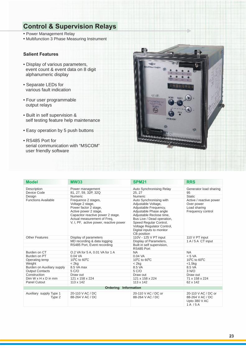
Salient Features
• Display of various parameters, event count & event data on 8 digit alphanumeric display
• Separate LEDs for various fault indication
• Four user programmable output relays
• Built in self supervision & self testing feature help maintenance
• Easy operation by 5 push buttons
• RS485 Port for serial communication with “MSCOM” user friendly software
DescriptionDevice CodeDesignFunctions Available
Other Features
Burden on CTBurden on PTOperating tempWeightBurden on Auxiliary supplyOutput ContactsConstructionDim W x H x D in mmPanel Cutout
Auxiliary supply Type 1 Type 2
Power management
0 0
81, 27, 59, 32P, 32QNumericFrequence 2 stages,Voltage 2 stage,Power factor 2 stage,Active power 2 stage,Capacitor reactive power 2 stage. Actual measurement of Freq,V, I, PF, active power, reactive power
Display of parametersMD recording & data loggingRS485 Port, Event recording
O.2 VA for 5 A, 0.01 VA for 1 A0.04 VA10 C to 60 C< 2kg8.5 VA max5 C/ODraw out 121 x 158 x 224113 x 142
20-110 V AC / DC88-264 V AC / DC
23
Control & Supervision Relays
Model MW33 SPM21
Auto Synchronising Relay25, 27NumericAuto Synchronising withAdjustable Voltage,Adjustable Frequency,Adjustable Phase angleAdjustable Reclose time,Bus Live / Dead operation,Speed Regular Control,Voltage Regulator Control,Digital inputs to monitorCB position110V - 125 V PT inputDisplay of Parameters,Built in self supervision,RS485 PortNA0.04 VA10 to 60< 2kg8.5 VA5 C/ODraw out121 x 158 x 224113 x 142
20-110 V AC / DC or88-264 V AC / DC
0 0C C
RRS
Generator load sharing95StaticActive / reactive powerOver powerLoad sharingFrequency control
110 V PT input1 A / 5 A CT input
NA< 5 VA10 C to 60 C<1.5kg8.5 VA3 N/ODraw out71 x 158 x 22462 x 142
20-110 V AC / DC or 88-264 V AC / DCUpto 380 V AC1 A / 5 A
0 0
• •
Power Management Relay Multifunction 3 Phase Measuring Instrument
Ordering Information

24
Wiring Diagrams
G
1 T
OPTO OPTO
VOIOCOS
Lood Shedding
SE
TT
ING
S
MEDIAAVERAGE
Operation
To other RRS Relays
INCREASE
DECREASE
OVER POWER
Freq. control
Open
OpenOpenOpen Open
OpenOpen
Open
Lood Shedding
YesYesYesYes
Open Yes
Close No
Freq. control
11
1
10
2 3 32
22 21
3
4
7
6
8
9
R1
R2
R3
15
12
13
1
2
17
18
14
(.) (.)
- -
+
+
+
+
-
-
-+
RRS
SPM21
DISPLAY
MICROP.
SPM21
FUNCTION
F25SXR1
R2
R3
R4
R5
PROGR.INT. FAULT
9 PIN MALE
CS-S+
2110
1122
9
8
1820
19
46
1517
16
143
21
34/382324KEYBORD
R5
R4
R3
R2
R1
F+
F-
U+
U-
5
7
BX
BR
SX
B.I.BR
52 (N.O.)
U
52 C
SPM21
UG
UB
G1
52
UB
L/+
N/-
12
13
44
41
30
29
26
25
UG
U
F
F
IEC 255
MW33
L/+
L/-
1/5A
1/5A
1/5A
25
26
27
283929
4130
3243
3142
33
Un
Un
44
12
13In = 5A In = 1A Un = 100V
_
=˜ ˜˜
KEYBOARDTASTIERA
PROGR.INT.FAULT
R5
DISPLAY
MICROP.
MW33FUNZIONIFINCTION
F32 W
F32 VAR
WhVARh
R1R2
R3R4
R5
R4
R3
R2
R1
14
3
2
CS-S+
9 PIN MALE
242334/38
12
3
1416
17155
641920188
9722111021 (21)
N.O.
N.C.
(10)
N.O.
N.C.
IEC 255

Voltage and Frequency Relays
Description
Device CodeDesignFunctions Available
RatingOther Features
Burden on CTBurden on PTOperating tempWeightBurden onA uxiliaryOutput Contacts
ConstructionDim W x H x D in mmPanel Cutout
Auxiliary Supply
25
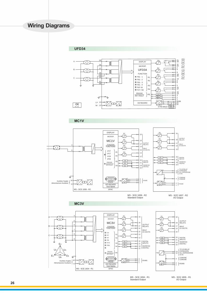
Model UFD34 MC1V MC3V
• •
3 Phase Volt ge and frequency relay with df/dt & dv/dt 1 Phase Voltage and frequency relay
a
3 Ph Volt ge and Frequency Relay81, 27, 59, df/dt, dv/dtNumericSelectable 4 stages of frequency as Under/Over frequencySelectable 2 stages of voltage as Under/Over voltageSelectable 2 stages of df/dtSelectable 1 stages of de/dtBlocking Output and Blocking InputTime tagged multiple event recording
100-125 VDisplay of parametersBuilt in self supervisionOscillogarphic recording of input quantitiesRS485 serial communication port on Back Panel
Not Applicable0.04 VA
0 0-10 C to 60 C<2.5Kg8.5 VA4 C/O Contacts + 1 C/O for Self supervisionDrawout121 x 164 x 224113 x 142
20-110 V AC/DC or88-264 V AC/DC
a Single phase Volt ge and Frequency Relay27, 59, 81NumericTwo Under Voltage elementsTwo Over Voltage elementsOne UnderFrequency elementOne OverFrequency elementBlocking Output and Blocking InputTime tagged multiple event recordingOscillogarphic wave form captureDisplay LCD 16 (2 x 8) characters
100-125 VDisplay of parametersBuilt inSelf supervisionModbus RTU / IEC870-5-103 Communication ProtocolsFront RS232 Port for Local ProgrammingOscillogarphic recording of input quantitiesRS485 serial comunication port on Back Panel0.1 VA for 1 A, 0.3 VA for 5 ANA
0 0-10 C to 55 C<1.5Kg<7 VA4 C/O Contacts + 1 C/O for Self supervisionDrawout83 x 164 x 22464 x 137
20-110 V AC/DC or88-264 V AC/DC
a 3 Ph Volt ge and Frequency Relay27, 59, 47, 59 V 0, 81NumericTwo Under Voltage elementsTwo Over Voltage elementsOne Under Frequency elementOne Over Frequency elementOne Zero Sequence Over Voltage ElementOne Negative Sequence Under Voltage ElementOne Positive Sequence Over Voltage ElementOscillographic wave form captureModbus RTU / IEC870-5-103Communication ProtocolsDisplay LCD 16 (2 x 8) characters
100-125 VDisplay of parametersBuilt in self supervisionModbus RTU / IEC870-5-103 Communication ProtocolsFront RS232 Port for Local ProgrammingOscillogarphic recording of input quantitiesRS485 serial communication port on Back Panel0.1 VA for 1 A, 0.3 VA for 5 ANA
0 0-10 C to 55 C<1.5Kg<7 VA4 C/O Contacts + 1 C/O for Self supervisionDrawout83 x 164 x 22464 x 137
20-110 V AC/DC or88-264 V AC/DC
a
Salient Features
•
•
•
•
•
Display of various parameters, tripcount & trip data on LCD screen
Separate LEDs for individual fault indication
Built in self supervision & self testing feature
RS485 port for serial communication with “MSCOM” software
Easy operation by push buttons
Ordering Information
UFD34
L/+
N/-
UFD34
Wiring Diagrams
A
B
C
25
26
27
283929
4130
12
13IEC 255
_
˜˜
˜=
KEYBOARD
PROGR.
INT. FAULTR5
R4
R3
R5
R4
R3
R2
R1
R2
R1DISPLAY
MICROP.
FUNCTION
F81 - 1
F81 - 2
F81 - 3
F81 - 4
Fdf / dt
F27 / 59
14
BI<
BI>
CS-S+
9 PIN MALE
242334/3812
31416
17155
6419
20188
972211
1021
(21)
N.O.
N.C.
(10)
N.O.
N.C.
26
BPMC
KEYBOARDTASTIERA
RS232
PROGR.
INT.FAULT R4
R3
R2
R11F27
FUNZIONIFUNCTIONS
MC1V
MICROP.
DISPLAY
R4
R3
R2
R1
D1
D2
D3
16
18
17
14
15
13
12
20
21
19
22
321
DIGITALINPUTS
INGRESSIDIGITALI
RELE’DI USCITA
OUTPUTRELAYS
C
A (S+)
B (S-)
R3
R2
R1 16
18
17
14
15
RELE’DI USCITA
OUTPUTRELAYS
20
21
19
22
1312
3
21
DIGITALINPUTS
INGRESSIDIGITALI
RS485
COMUNECOMUNE
TO I/0 RELAYEXPANSIONALL ESPANSIONEDI I/0
D3
D1
D2
HL
C
A (S+)
B (S-)
RS485
2F27
1F59
2F59
Auxiliary Supply
Alimentazione Ausiliaria
MS - SCE 1836 - R2
MS - SCE 1837 - R2I/O Output
MS - SCE 1836 - R2Standard Output
4
5
10
11
MC1V
BPMC
KEYBOARDTASTIERA
RS232
PROGR.
INT.FAULT
R4
R3
R2
R1F24
F27
F47
F59
F27d
F59d
FUNZIONIFUNCTIONS
MC3V
MICROP.
DISPLAY
R4
R3
R2
R1
D1
D2
D3
16
18
17
14
15
13
12
20
21
19
22
321
DIGITALINPUTS
INGRESSIDIGITALI
RELE’DI USCITA
OUTPUTRELAYS
C
A (S+)
B (S-)RS485
R5
R3
R2
R1 16
18
17
14
15
RELE’DI USCITA
OUTPUTRELAYS
20
21
19
22
1312
3
21
DIGITALINPUTS
INGRESSIDIGITALI
RS485
COMUNECOMUNE
TO I/0 RELAYEXPANSIONALL ESPANSIONEDI I/0
D3
D1
D2
H
L
C
A (S+)
B (S-)
4
5
6
7
8
9
A
B
C
EA
UAUC
UBEBEC
10
11
Auxiliary Supply
Alimentazione Ausiliaria
MS - SCE 1834 - R1
MS - SCE 1834 - R1Standard Output
MS - SCE 1835 - R1I/O Output
MC3V