digital protective relays -...
TRANSCRIPT
Digital Protective Relays
Larsen & Toubro
Mysore Works
Larsen & Toubro infuses engineering with imagination. The Company offers a wide
range of advanced solutions in the field of Engineering, Construction, Electrical &
Automation, Machinery and Information Technology.
L&T Switchgear, a part of the Electrical & Automation business, is India's largest
manufacturer of low voltage switchgear, with the scale, sophistication and range to
meet global benchmarks. With over five decades of experience in this field, the
Company today enjoys a leadership position in the Indian market with a growing
international presence.
It offers a complete range of products including powergear, controlgear, industrial
automation, building electricals & automation, reactive power management, energy
meters, and protective relays. These products conform to Indian and International
Standards.
L&T limited offers a wide range of Microprocessor based State-of-the-art
digital protective relays suitable for LV, MV and HV power distribution systems. These
relays are manufactured at L&T’s Mysore works equipped with modern infrastructure
and employing latest manufacturing and testing equipments. L&T’s range also include
relays for special applications manufactured by Microelettrica Scientifica, Italy. The
applications include Feeder Management, Load Sharing, Load Shedding,
Synchronising, Grid Islanding etc.
L&T also manufactures a range of electronic single phase energy meters, three phase energy meters and trivector meters at the Mysore works.
Pages
1
2
3
5
7
9
11
13
15
17
19
23
25
Control & Supervision Relays - MW33
Synchronising Load Sharing Relays - SPM21, RRS
ANSI / IEEE Device Function Number Details
Time - Current Characteristics
Over Current Relays & Earth fault Relays - MC31A, MC61A, MC61C
Current Sensing Relays - MC12A, ME12A, SC14S
Power Factor Control Relays - RPM14, RPM08
Motor Protection Relays - MM30, MM30W, N-DIN-MA
Feeder Protection Relays - MC20, MC30, FMR
Vector Surge Protection Relay - UM30A
Reverse Power Relay - MRP11
Voltage Relay - MV12
Contents
MCOMP, MPR300
Generator Protection Relays - MG30, MG30I, MD32G
Transformer Protection Relays - IM30T, MD32T, MD32TM
Voltage and Frequency Relays - MC1V, MC3V, UFD34
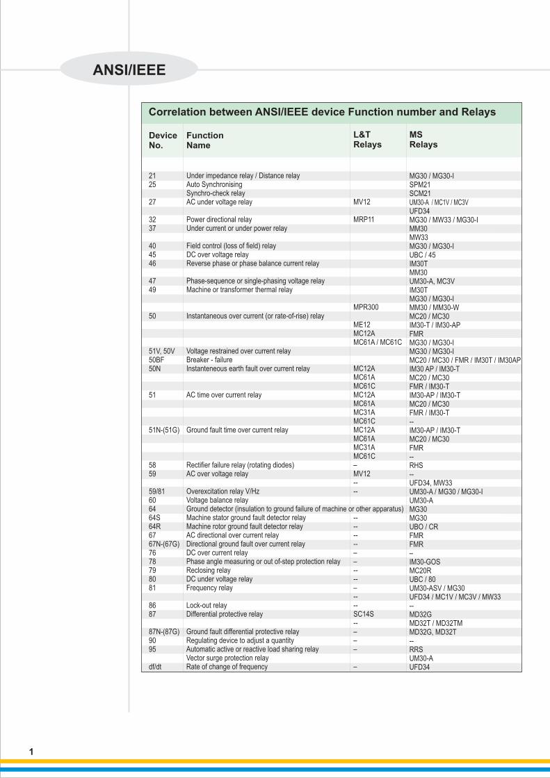
Correlation between ANSI/IEEE device Function number and Relays
Function Name
Device No.
L&T Relays
MS Relays
Under impedance relay / Distance relay Auto Synchronising Synchro-check relayAC under voltage relay
Power directional relayUnder current or under power relay
Field control (loss of field) relayDC over voltage relayReverse phase or phase balance current relay
Phase-sequence or single-phasing voltage relayMachine or transformer thermal relay
Instantaneous over current (or rate-of-rise) relay
Voltage restrained over current relayBreaker - failure Instanteneous earth fault over current relay
AC time over current relay
Ground fault time over current relay
Rectifier failure relay (rotating diodes)AC over voltage relay
Overexcitation relay V/HzVoltage balance relayGround detector (insulation to ground failure of machine or other apparatus)Machine stator ground fault detector relayMachine rotor ground fault detector relayAC directional over current relayDirectional ground fault over current relayDC over current relayPhase angle measuring or out of-step protection relayReclosing relayDC under voltage relayFrequency relay
Lock-out relayDifferential protective relay
Ground fault differential protective relayRegulating device to adjust a quantityAutomatic active or reactive load sharing relay Vector surge protection relay Rate of change of frequency
MV12
MRP11
M
ME12MC12AMC61A / MC61C
MC12AMC61AMC61CMC12AMC61AMC31AMC61CMC12AMC61AMC31AMC61C–MV12----
--------––----–----SC14S--–––
–
PR300
MG30 / MG30-ISPM21SCM21UM30-A / MC1V / MC3V
UFD34MG30 / MW33 / MG30-IMM30MW33MG30 / MG30-IUBC / 45IM30TMM30UM30-A, MC3VIM30TMG30 / MG30-IMM30 / MM30-WMC20 / MC30IM30-T / IM30-APFMRMG30 / MG30-I MG30 / MG30-IMC20 / MC30 / FMR / IM30T / IM30APIM30 AP / IM30-TMC20 / MC30FMR / IM30-TIM30-AP / IM30-TMC20 / MC30FMR / IM30-T--IM30-AP / IM30-TMC20 / MC30FMR--RHS--UFD34, MW33UM30-A / MG30 / MG30-IUM30-AMG30MG30UBO / CRFMRFMR–IM30-GOS MC20RUBC / 80UM30-ASV / MG30 UFD34 / MC1V / MC3V / MW33--MD32GMD32T / MD32TMMD32G, MD32T--RRSUM30-AUFD34
2125 27 3237 404546 4749
50
51V, 50V50BF 50N
51
51N-(51G)
5859 59/81 606464S64R6767N-(67G)7678798081 8687
87N-(87G)9095
df/dt
1
ANSI/IEEE
2
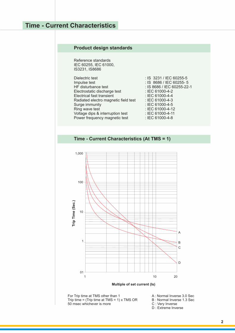
Time - Current Characteristics (At TMS = 1)
A : Normal Inverse 3.0 SecB : Normal Inverse 1.3 SecC : Very InverseD : Extreme Inverse
For Trip time at TMS other than 1Trip time = (Trip time at TMS = 1) x TMS OR 50 msec whichever is more
Product design standards
Reference standardsIEC 60255, IEC 61000, IS3231, IS8686
Dielectric test : IS 3231 / IEC 60255-5 Impulse test : IS 8686 / IEC 60255- 5 HF disturbance test : IS 8686 / IEC 60255-22-1 Electrostatic discharge test : IEC 61000-4-2Electrical fast transient : IEC 61000-4-4Radiated electro magnetic field test : IEC 61000-4-3Surge immunity : IEC 61000-4-5Ring wave test : IEC 61000-4-12Voltage dips & interruption test : IEC 61000-4-11Power frequency magnetic test : IEC 61000-4-8
Multiple of set current (Is)
Tri
p T
ime
(S
ec
.)
A
B
C
D
1,000
100
10
1
01
1 10 20
Time - Current Characteristics

Salient Features • Display of currents, settings, Trip data & Trip history for analysis & trouble shooting
• Built in self supervision & self testing feature to ensure continuous reliability
• Separate indication for power ON & programming mode on relay fault
• Separate fault indication
• In MC61C - Communication with computer & breaker control through RS485 Port
• Four user programmable output relays
Over Current and Earth Fault Relays• Three Phase Over Current & Earth fault Relays
3
Description
Device Code
Design
Functions Available
Settings
Other Features
Burden on CT
Burden on PT
Operating temp
Weight
Burden on Auxiliary supply
Output Contact
Construction
Dim W x H x D in mm
Panel Cut out
Auxiliary supply Type 1
Type 2
CT Rating
Output Contacts
3 Phase O/C + E/F
0C
51 RYBN
Numerical Relay
Lowset O/C -Is
Lowset E/F -Os
O/C Is = 20-200% Step 5%
E/F Os = 5-80% Step 5%
Time Characteristics available -
NI, VI, EI, Definite Time
TMS 0.1 - 1.6 Step 0.05
Site selectable Trip time Char.
Display of Currents, Trip count
Self supervision feature
� 0.25 VA on CT/Phase
Not applicable00 to 60 C
< 2kg
� 10 VA
1 N/O Contact for self suprvn
Draw out
121 x 158 x 224
113 x 142
20-110 V AC / DC or
88-264 V AC / DC
1 A or 5 A
(site selectable)
4 NO or 2 NO + 2 NC
3 Phase O/C + E/F + Highset
0 0C
50/51 RYBN
Numerical Relay
Lowset O/C -Is
Highset O/C -Ihs
Lowset E/F -Os
Highset E/F -Ohs
O/C Is = 20-200% Step 5%
E/F Os = 5-80% Step 5%
HS O/C = (0.2 to 40) x In step of -
0.2 In or disable
HS E/F = (0.1 to 20) x On step of -
0.1 On or disable
Time Characteristics available -
NI, VI, EI, Definite Time
TMS : 0.1 - 1.6 Step 0.05
Site selectable Trip time Char.
Highset can be disabled
Display of Currents, Trip count
Self supervision feature
� 0.25 VA on CT/Phase
Not applicable
0 to 60 C
< 2kg
� 10 VA
1 N/O Contact for self suprvn
Draw out
121 x 158 x 224
113 x 142
20-110 V AC / DC or
88-264 V AC / DC
1 A or 5 A
(site selectable)
4 NO or 2 NO + 2 NC
3 Phase O/C + E/F + Highset
Communication and breaker control
0 0C
50/51 RYBN
Numerical Relay
Lowset O/C -Is
Highset O/C -Ihs
Lowset E/F -Os
Highset E/F -Ohs
O/C Is = 20-200% Step 5%
E/F Os = 5-80% Step 5%
HS O/C = (0.2 to 40) x In step of -
0.2 In or disable
HS E/F = (0.1 to 20) x On step of -
0.1 On or disable
Time Characteristics available -
NI, VI, EI, Definite Time
TMS : 0.1 - 1.6 Step 0.05
HS delay:0.1-2 Sec step 0.01 -
Sec. or Inst.
RS485 Communication
Breaker control
Auto doubling of highset, -
Relay co-ordination - BI & BO
� 0.25 VA on CT/Phase
Not applicable
0 to 60 C
< 2kg
� 10 VA
1 N/O Contact for self suprvn, 1N/O for trip
Draw out
121 x 158 x 224
113 x 142
20-110 V AC / DC or
88-264 V AC / DC
1 A or 5 A
(not site selectable)
4 NO
MC61A MC61CModel MC31A
Ordering Information
MC31A
MC61A
MC61C
MC61A
MC31A
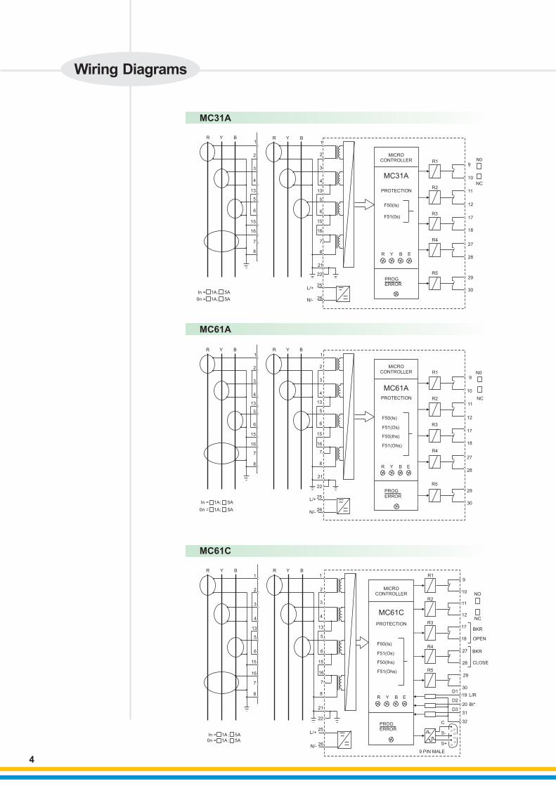
Wiring Diagrams
R Y B R Y B1
2
4
13
5
6
15
16
7
8
3 3
1
2
4
13
5
6
15
16
7
8
22
25
26
21
L/+
N/-
In = 1A; 5A
0n = 1A; 5A
MICRO CONTROLLER
PROTECTION
F50(Is)
F51(0s)
R Y B E
PROGERROR
R1
R2
R3
R4
R5
N0
NC
9
10
11
12
17
18
27
28
29
30˜
R Y B R Y B1
2
4
13
5
6
15
16
7
8
3 3
1
2
4
13
5
6
15
16
7
8
22
25
26
21
In = 1A; 5A
0n = 1A; 5A
L/+
N/-
MICRO CONTROLLER
PROTECTION
F50(Is)
F51(Os)
F50(Ihs)
F51(Ohs)
R Y B E
R1
R2
R3
R4
R5
N0
NC
9
10
11
12
17
18
27
28
29
30
In = 1A ; 5A
0n = 1A ; 5A
R Y B R Y B1
2
4
13
5
6
15
16
7
8
3 3
1
2
4
13
5
6
15
16
7
8
22
25
26
21
L/+
N/-
˜
MICRO CONTROLLER
MC61C
PROTECTION
F50(Is)
F51(Os)
F50(Ihs)
F51(Ohs)
R Y B E
PROGERROR
R1
R2
R3
R4
R5
9
10
11
12
17
18
27
28
29
30
19
20
31
32
NO
NC
BKR
OPEN
CLOSE
BKR
L/R
BI*
C
S-
S+
9 PIN MALE
D1
D2
D3
4
PROG.ERROR
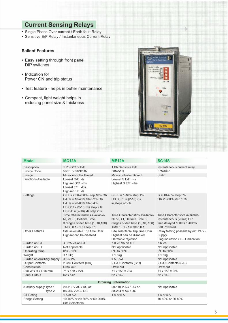
Salient Features
• Easy setting through front panel DIP switches
• Indication for Power ON and trip status
• Test feature - helps in better maintenance • Compact, light weight helps in reducing panel size & thickness
5
••
Single Phase Over current / Earth fault Relay
Sensitive E/F Relay / Instantaneous Current Relay
Current Sensing Relays
Model SC14S
Description
Device Code
Design
Functions Available
Settings
Other Features
Burden on CT
Burden on PT
Operating temp
Weight
Burden on Auxiliary supply
Output Contacts
Construction
Dim W x H x D in mm
Panel Cutout
Auxiliary supply Type 1
Type 2
CT Rating
Range Setting
1 Ph O/C or E/F
0 0C
or
50/51 or 50N/51N
Microcontroller Based
Lowset O/C -Is
Highset O/C -Ihs
Lowset E/F -Os
Highset E/F -Is
O/C Is = 50-200% Step 10% OR
E/F Is = 10-40% Step 2% OR
E/F Is = 20-80% Step 4%
HS O/C = (2-16) xls step 2 Is
HS E/F = (2-16) xls step 2 Is
Time Characteristics available-
Nl, VI, EI, Definite Time
3 ranges of def Time (1, 10,100)
TMS : 0.1 - 1.6 Step 0.1
Site selectable Trip time Char.
Highset can be disabled
0.25 VA on CT
Not applicable
0 - 60 C
< 1.5kg
5.5 VA
2 C/O Contacts (S/R)
Draw out
71 x 158 x 224
62 x 142
20-110 V AC / DC or
88-264 V AC / DC
1 A or 5 A
10-40% or 20-80% 50-200%
Site Selectable
Instantaneous current relay
0 0C
87N/64R
Static
Is = 10-40% step 5%
OR 20-80% step 10%
Time Characteristics available-
Instantaneous (25ms) OR
time delayed 100ms / 200ms
Self Powered
Relay testing possible by ext. 24 V -
Supply
Flag indication / LED indication
6 VA
Not Applicable
0 to 60 C
< 1.5kg
Not Applicable
2 C/O Contacts (S/R)
Draw out
71 x 158 x 224
62 x 142
Not Applicable
1 A or 5 A
10-40% or 20-80%
1 Ph Sensitive E/F
Time Characteristics available-
NI, VI, EI, Definite Time 3
ranges of def Time (1, 10, 100)
TMS : 0.1 - 1.6 Step 0.1
Site selectable Trip time Char.
Highset can be disabled
Harmonic rejection
0.25 VA on CT
Not applicable0 00 C to 60 C
< 1.5kg
5.5 VA
2 C/O Contacts (S/R)
Draw out
71 x 158 x 224
62 x 142
20-110 V AC / DC or
88-264 V AC / DC
1 A or 5 A
50N/51N
Microcontroller Based
Lowset S E/F -Is
Highset S E/F -Ihs.
S E/F = 1-16% step 1%
HS S E/F = (2-16) xls
in steps of 2 ls
MC12A ME12A
Ordering Information

MC12A / ME12A
SC14S
6
1
2 +VE/PH.
-VE/NR1
COM
COM
SETTING RANGE (Is)
Aux. Supply
μP. ControlCkt.
F50/50NF51/51N
3
10
11
12
1AIn MC12A
(10-40)% In(20-80)% In(50-200)% In
ME12(1-16)% In
5A
AUX SUPPLY24 - 110V AC/DC95 - 240V AC/DC
MC12A / ME12
11
10
9
7+
8
12
SC14S
Test (24V)Voltage
DC-DC
Convrt.
Test
ControlCkt.
R
2
1
3
5
6
4
In1A5A
CT OPERATED RELAYNO AUXILIARY SUPPLY REQUIRED
SETTING RANGE (Is)(10-40)% IN(20-80)% IN
˜
Wiring Diagrams
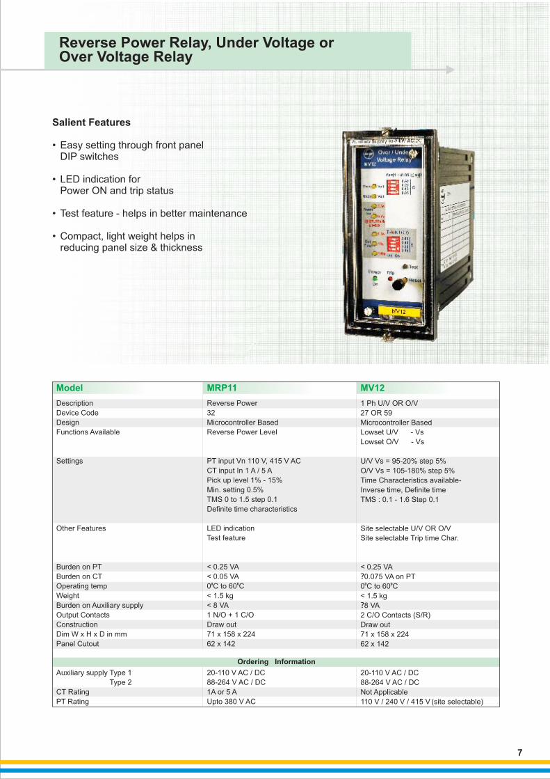
Salient Features
• Easy setting through front panel DIP switches
• LED indication for Power ON and trip status
• Test feature - helps in better maintenance • Compact, light weight helps in reducing panel size & thickness
7
Reverse Power Relay, Under Voltage or Over Voltage Relay
Model MRP11 MV12
Description
Device Code
Design
Functions Available
Settings
Other Features
Burden on PT
Burden on CT
Operating temp
Weight
Burden on Auxiliary supply
Output Contacts
Construction
Dim W x H x D in mm
Panel Cutout
Auxiliary supply Type 1
Type 2
CT Rating
PT Rating
Microcontroller Based
Lowset U/V - Vs
Lowset O/V - Vs
U/V Vs = 95-20% step 5%
O/V Vs = 105-180% step 5%
Time Characteristics available-
Inverse time, Definite time
TMS : 0.1 - 1.6 Step 0.1
Site selectable U/V OR O/V
Site selectable Trip time Char.
? 0.075 VA on PT
0 to 60 C
< 1.5 kg
? 8 VA
2 C/O Contacts (S/R)
Draw out
71 x 158 x 224
62 x 142
20-110 V AC / DC
88-264 V AC / DC
Not Applicable
110 V / 240 V / 415 V (site selectable)
1 Ph U/V OR O/V
27 OR 59
< 0.25 VA
0 0C
Microcontroller Based
Reverse Power Level
PT input Vn 110 V, 415 V AC
CT input In 1 A / 5 A
Pick up level 1% - 15%
Min. setting 0.5%
TMS 0 to 1.5 step 0.1
Definite time characteristics
LED indication
Test feature
< 0.25 VA
< 0.05 VA
0 to 60 C
< 1.5 kg
< 8 VA
1 N/O + 1 C/O
Draw out
71 x 158 x 224
62 x 142
20-110 V AC / DC
88-264 V AC / DC
1A 5 A
Upto 380 V AC
Reverse Power
32
0 0C
or
Ordering Information
8
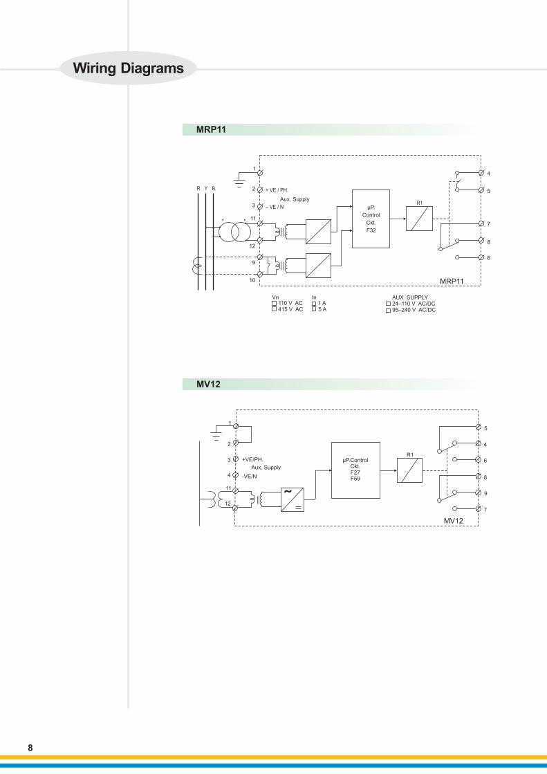
MRP11
R Y
14
5
7
8
6
11
μP.
Control
Ckt.
F32
R1
Vn110 V AC 1 A415 V AC 5 A
In AUX SUPPLY24–110 V AC/DC95–240 V AC/DC
MRP11
12
2 + VE / PH.
– VE / N
Aux. Supply3
9
10
B
MV12
5
4
6
8
9
7
R1μP.Control
Ckt.F27F59
1
2
3
11
12
MV12
+VE/PH.
Aux. Supply
-VE/N4
Wiring Diagrams

• (8 & 14 Stages) Intelligent Power Factor Controller Relay
Salient Features
•
•
•
• On line display of system PF
• Easy setting through - front panel push button
Suitable for non-uniform banks
• LED indication for alarm code, no. of Banks selected, PF status- lead / lag / unity
Auto / Manual mode
Measurement sensitivity of 1%
• Automatic C/K correction
• Display of cuttent, Voltage, kVAr, & Capacitor values
Power Factor Control Monitoring Relays
RPM-8Model
Description
Device Code
Design
Functions Available
Settings
Other Features
Burden on CT
Burden on PT
Operating temp
Weight
Output Contacts
Dim W x H x D in mm
Panel Cutout
Auxiliary supply
Automatic
Microcontroller Based
Automatic PF control upto
8 stage
Switching time 1-255 Sec.
in step of 1 sec for same
Bank switching
Auto C/K sellection
PF control range 1% to 120% of
rated current
Can accept unequal banks
Display of PF, V, l, kVAr
LED indications for faults
Alarm signal for CT reversal,
under current, Under compensation,
over compensation, over voltage,
1 A / 5 A field selectable
0.3 VA
15 VA00 to 60 C
< 2kg
8 N/O
1 N/O contact for alarm
144 x 144 x 100
138 x 138
240 V AC
Power Factor Controller
8 stage
0C
RPM-14
Automatic
Microcontroller Based
Automatic PF control upto
14 stage
Switching time 1-255 Sec.
in step of 1 sec for same
Bank switching
Auto C/K sellection
PF control range 1% to 120% of
rated current
Can accept unequal banks
Display of PF, V, l, kVAr
LED indications for faults
Alarm signal for CT reversal,
under current, Under compensation,
over compensation, over voltage,
1 A / 5 A field selectable
0.3 VA
15 VA00 to 60 C
< 2kg
14 N/O
1 N/O contact for alarm
144 x 144 x 100
138 x 138
240 V AC
Power Factor Controller
14 stage
0C
Ordering Information
9
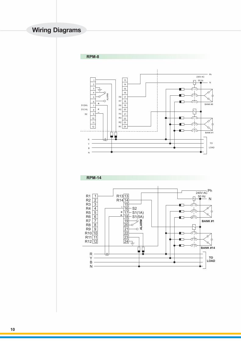
RPM-8
RPM-14
123456789101112
R1R2R3R4R5R6R7R8R9R10R11R12
131415161718192021222324
R13R14
-
++
RYBN
S2S1(1A)S1(5A)
AL
AR
M
Ph240V AC
50 HzN
BANK #1
BANK #14
TOLOAD
1
2
3
4
5
6
7
8
9
10
11
12
S1(5A)
S1(1A)
S2
ALA
RM
+
+-
R
Y
B
N
R8
R7
R6
R5
R4
R3
R2
R1
13
14
15
16
17
18
19
20
21
22
23
24
Ph230V AC
50 HzN
BANK #8
TO
LOAD
BANK #1
Wiring Diagrams
10
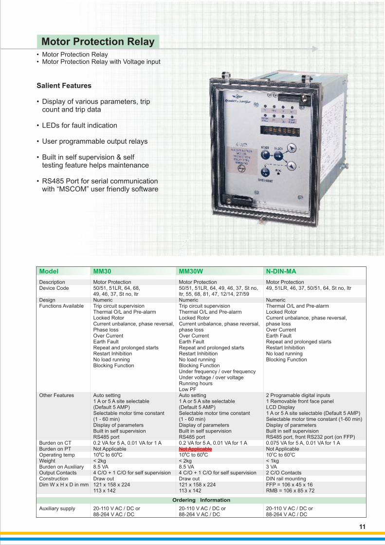
• Motor Protection Relay• Motor Protection Relay with Voltage input
Motor Protection Relay
Salient Features
• Display of various parameters, trip count and trip data
• LEDs for fault indication
• User programmable output relays
• Built in self supervision & self testing feature helps maintenance
• RS485 Port for serial communication with “MSCOM” user friendly software
DescriptionDevice Code
DesignFunctions Available
Other Features
Burden on CTBurden on PTOperating tempWeightBurden on AuxiliaryOutput ContactsConstructionDim W x H x D in mm
Auxiliary supply
Motor Protection50/51, 51LR, 64, 68, 49, 46, 37, St no, ltr
0 0
NumericTrip circuit supervision Thermal O/L and Pre-alarmLocked RotorCurrent unbalance, phase reversal, Phase lossOver CurrentEarth FaultRepeat and prolonged startsRestart InhibitionNo load runningBlocking Function
Auto setting1 A or 5 A site selectable(Default 5 AMP)Selectable motor time constant (1 - 60 min)Display of parametersBuilt in self supervisionRS485 port0.2 VA for 5 A, 0.01 VA for 1 ANot Applicable 10 C to 60 C< 2kg8.5 VA4 C/O + 1 C/O for self supervisionDraw out121 x 158 x 224113 x 142
20-110 V AC / DC or88-264 V AC / DC
Model MM30
Motor Protection
0 0C
49, 51LR, 46, 37, 50/51, 64, St no, Itr
NumericThermal O/L and Pre-alarmLocked RotorCurrent unbalance, phase reversal, phase lossOver CurrentEarth FaultRepeat and prolonged startsRestart InhibitionNo load runningBlocking Function
2 Programable digital inputs1 Removable front face panelLCD Display1 A or 5 A site selectable (Default 5 AMP)Selectable motor time constant (1-60 min)Display of parametersBuilt in self supervisionRS485 port, front RS232 port (on FFP)0.075 VA for 5 A, 0.01 VA for 1 ANot Applicable 10 to 60 C< 1kg3 VA2 C/O ContactsDIN rail mountingFFP = 106 x 45 x 16RMB = 106 x 85 x 72
20-110 V AC / DC or88-264 V AC / DC
N-DIN-MA
Motor Protection50/51, 51LR, 64, 49, 46, 37, St no,ltr, 55, 68, 81, 47, 12/14, 27/59
0 0
NumericTrip circuit supervision Thermal O/L and Pre-alarmLocked RotorCurrent unbalance, phase reversal, phase lossOver CurrentEarth FaultRepeat and prolonged startsRestart InhibitionNo load runningBlocking FunctionUnder frequency / over frequency Under voltage / over voltage Running hours Low PF Auto setting1 A or 5 A site selectable (Default 5 AMP)Selectable motor time constant (1 - 60 min)Display of parametersBuilt in self supervisionRS485 port0.2 VA for 5 A, 0.01 VA for 1 ANot Applicable 10 C to 60 C< 2kg8.5 VA4 C/O + 1 C/O for self supervisionDraw out121 x 158 x 224113 x 142
20-110 V AC / DC or88-264 V AC / DC
MM30W
Ordering Information
11
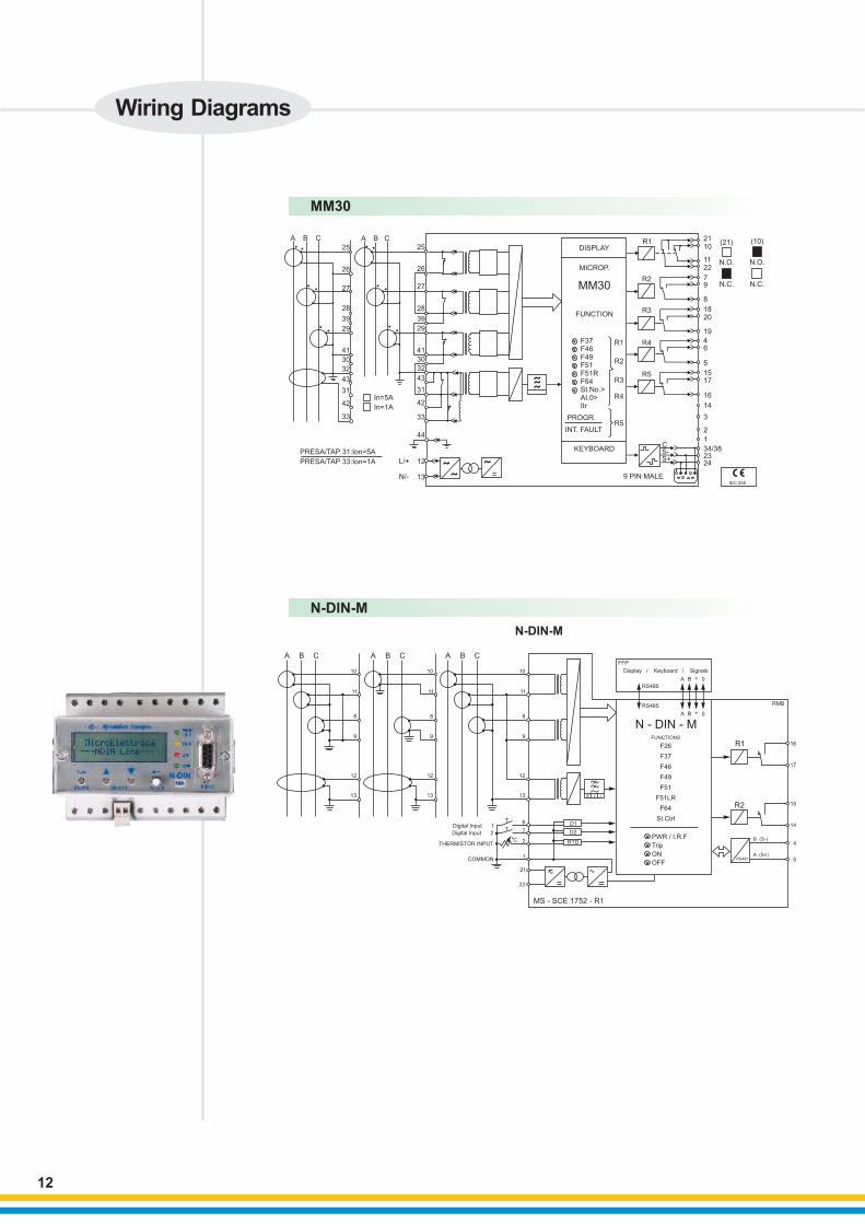
MM30
N-DIN-M
L/+
N/-
A B C A B C
25
26
27
28
29
41
30
32
39
25
26
27
28
39
29
41
30
32
43
31
42
33
43
31
42
33
44
In=1A
In=5A
PRESA/TAP 31:Ion=5A
PRESA/TAP 33:Ion=1A 12
13 ˜˜
˜
˜̃̃
=
DISPLAY
MICROP.
MM30
FUNCTION
F37F46F49F51F51RF64St.No.>AI.0>Itr
PROGR.
INT. FAULT
KEYBOARD
R1
R2
R3
R4
R5
R1
R2
R3
R4
R5
9 PIN MALE
(21) (10)
N.O. N.O.
N.C. N.C.
2110
1122
79
8
1820
19
46
5
1517
16
14
3
2
1
34/382324
CS-S+
IEC 255
A B C A B C A B C
10
11
8
9
12
13
10
11
8
9
12
13
10
11
8
9
12
13
6
7
2
1
21
22
0C
T
TDigital Input 1
Digital Input 2
THERMISTOR INPUT
COMMON
BT 2 1
D1
D2
RTD
MS - SCE 1752 - R1
FFP
Display / Keyboard / Signals
RS485
RS485
A B + 0
A B + 0
N - DIN - MFUNCTIONS
F26
F37
F46
F49
F51
F51LR
F64
St.Ctrl
PWR / I.R.F
Trip
ON
OFF
R1
RMB
R2
B (S-)
A (S+)RS485
16
17
15
14
4
5
N-DIN-M
Wiring Diagrams
12
MCOMPModel MPR 300
Motor Protection
49, 14, 46, 50N, 3, 59, 27, 47,
81H, 81L, 66, 27LV, 47a, 47b
Numeric
Thermal Over load
Locked rotor
Current unbalance
Phase loss
Under current
Over Voltage
Under Voltage
Over Frequency
Under frequency
Max. no. of starts
Reacceleration
Phase reversal
Intelligent relay with separate
protection, display and CT
modules
Suitable for 50/ 60 Hz
Can be used with DOL,
RDOLand Star delta starters
Communication options -
Modbus RTU, Modbus TCP IP
and Prof bus
Not Applicable
Not Applicable
10 to 60° C
< 2kg
< 8VA
4C/O
Split Protection unit 92 x 123 x 103.95
Display - 92 x 92
80 - 300 VAC/ 80 - 240 VDC
Description
Device Code
Design
Functions Available
Other Features
Burden on PT
Burden on CT
Operating temp
Weight
Output Contacts
Dim W x H x D in mm
Panel Cutout
Auxiliary supply
Burden on Auxiliary supply
Motor Protection
49, 51LR, 64, 46, 37
Numeric
Thermal overload
Locked Rotor
Earth fault
Single phasing
No load running
up to 88A
Trip time characteristics
as per
IEC947
Not Applicable
Not Applicablec
0-60 C
< 0.5kg.
< 8VA
1NO+1NC
Not applicable
Not applicable
240V AC
13
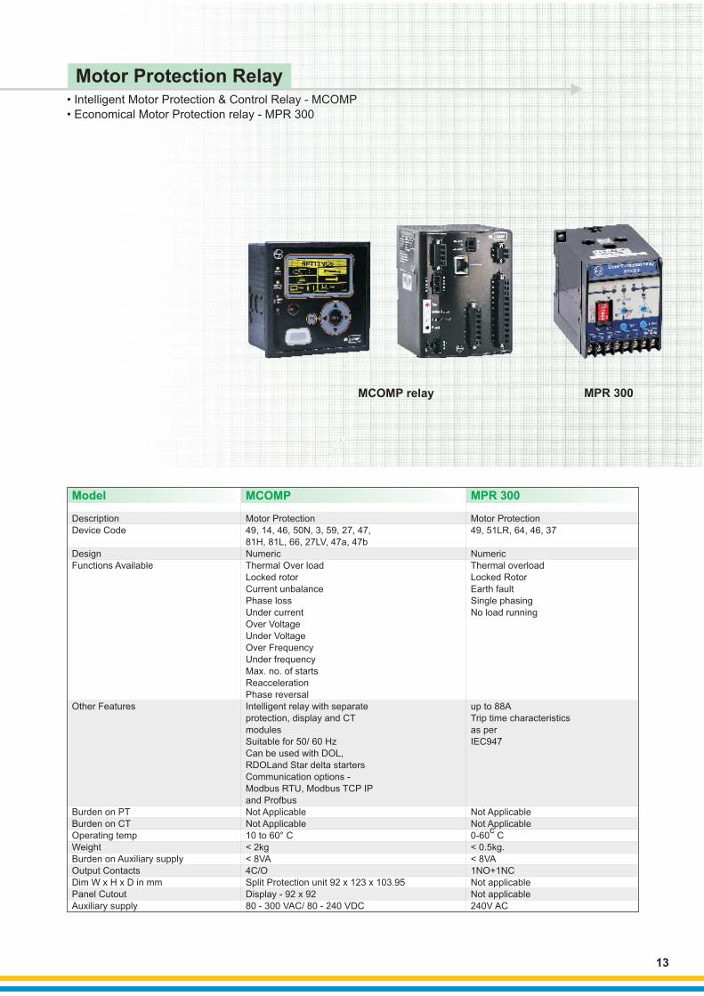
•
•
Intelligent Motor Protection & Control Relay - MCOMP
Economical Motor Protection relay - MPR 300
Motor Protection Relay
MPR 300 MCOMP relay
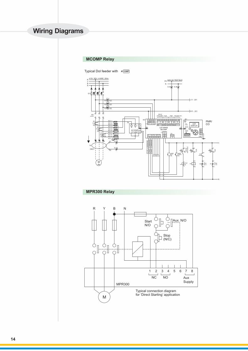
Wiring Diagrams
MCOMP Relay
MPR300 Relay
14
M
1 2 3 4 5 6 7 8
NC NO
MPR300
Aux
Supply
R Y B N
StartN/O
Stop(N/C)
Typical connection diagramfor ‘Direct Starting’ application
Aux. N/O
240V AC TEST BUS
L11 - 201
N11 - 201
PH
N
X-25 X-26 TT
415V, 3PH, 4-WIRE, 50HzRYB
N
Q1
NL
K
111 112
121 122
131 132
6A
6A
6A
F11
F12
F13
K4
2 4 6
1 3 5
R Y B
T4
CBCT
T1P2
P1 S1
S2
XC1-1
XC1-2XC1-3
XC1-4
XC1-5XC1-6
XC1-7
XC1-8XC1-9
XC1-10
T2
P2
P1 S1
S2
S1
S2
R Y B
T5
CB
CTM OOMP
CT UNIT
T3P2
P1
M
X-42
X-43
S
SS2
S1
DRIVEAVAILABLE RUN TRIP UNUSED DO
K3
C1
C2
1 2 3 8N B Y RREF. VOLTAGE
8181 82 83 84 85 86 87 88 89 90 91 92
C8
L&T MAKEMCOMP
C7C4
C3
DIGITAL OUTPUT RELAY
C6
61 62 63 64 65 66 67
DIGITAL INPUTS
AUX.VOLT
N PH
71 72
RS485
D1
LEDDISPLAY
75
76
77
P
N
E
UNUSED DI
ST
OP
CO
MM
AN
D
STA
RT
CO
MM
AN
D
STA
RT
CO
MM
AN
D
MOTORSTATUS
K3
106 106 10682 83 85 86
K3 K381 84 87
88 89
RU
N
K4
TR
IP
43
44
PH
S111
STOP
P.B12
K4
N
A1
A2
21
22
11
12
H2R
H1GR
UN
L
ED
TR
IPLE
D
HANDRSTP.B.
HANDSTARTP.B.
PMR/CO
ALARMPICKUP
PMR/COMM
TRIP
ESE
ESC
ELECT
DR
IVE
AV
AIL
AB
LE
M COMP
Typical Dol feeder with M COMP
• Multifunction Generator Protection Relays• Percentage Based Generator Differential Relay
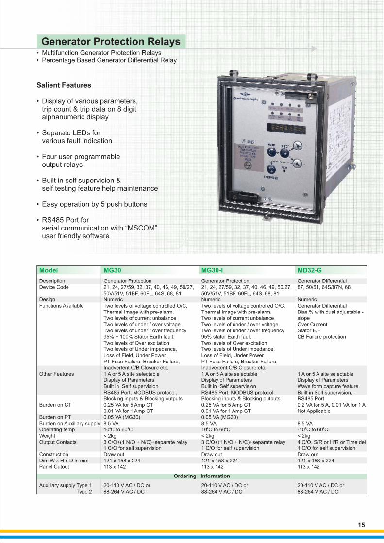
Generator Protection Relays
Salient Features
• Display of various parameters, trip count & trip data on 8 digit alphanumeric display
• Separate LEDs for various fault indication
• Four user programmable output relays
• Built in self supervision & self testing feature help maintenance
• Easy operation by 5 push buttons
• RS485 Port for serial communication with “MSCOM” user friendly software
Description
Device Code
Design
Functions Available
Other Features
Burden on CT
Burden on PT
Burden on Auxiliary supply
Operating temp
Weight
Output Contacts
Construction
Dim W x H x D in mm
Panel Cutout
Auxiliary supply Type 1
Type 2
Generator Protection
21, 24, 27/59, 32, 37, 40, 46, 49,
0 0C
3 C/O+(1 N/O + N/C)+separate relay
1 C/O for self supervision
50/27,
50V/51V, 51BF, 60FL, 64S, 68, 81
Numeric
Two levels of voltage controlled O/C,
Thermal Image with pre-alarm,
Two levels of current unbalance
Two levels of under / over voltage
Two levels of under / over frequency
95% + 100% Stator Earth fault,
Two levels of Over excitation
Two levels of Under impedance,
Loss of Field, Under Power
PT Fuse Failure, Breaker Failure,
Inadvertent C/B Closure etc.
1 A or 5 A site selectable
Display of Parameters
Built in Self supervision
RS485 Port, MODBUS protocol.
Blocking inputs & Blocking outputs
0.25 VA for 5 Amp CT
0.01 VA for 1 Amp CT
0.05 VA (MG30)
8.5 VA
10 to 60 C
< 2kg
Draw out
121 x 158 x 224
113 x 142
20-110 V AC / DC or
88-264 V AC / DC
Generator Differential
0 0C
87, 50/51, 64S/87N, 68
Numeric
Generator Differential
Bias % with dual adjustable -
slope
Over Current
Stator E/F
CB Failure protection
1 A or 5 A site selectable
Display of Parameters
Wave form capture feature
Built in Self supervision, -
RS485 Port
0.2 VA for 5 A, 0.01 VA for 1 A
Not Applicable
8.5 VA
-10 to 60 C
< 2kg
4 C/O, S/R or H/R or Time del
1 C/O for self supervision
Draw out
121 x 158 x 224
113 x 142
20-110 V AC / DC or
88-264 V AC / DC
Model MG30 MD32-G
Generator Protection
21, 24, 27/59, 32, 37, 40, 46, 49,
0 0C
3 C/O+(1 N/O + N/C)+separate relay
1 C/O for self supervision
50/27,
50V/51V, 51BF, 60FL, 64S, 68, 81
Numeric
Two levels of voltage controlled O/C,
Thermal Image with pre-alarm,
Two levels of current unbalance
Two levels of under / over voltage
Two levels of under / over frequency
95% stator Earth fault
Two levels of Over excitation
Two levels of Under impedance,
Loss of Field, Under Power
PT Fuse Failure, Breaker Failure,
Inadvertent C/B Closure etc.
1 A or 5 A site selectable
Display of Parameters
Built in Self supervision
RS485 Port, MODBUS protocol.
Blocking inputs & Blocking outputs
0.25 VA for 5 Amp CT
0.01 VA for 1 Amp CT
0.05 VA (MG30)
8.5 VA
10 to 60 C
< 2kg
Draw out
121 x 158 x 224
113 x 142
20-110 V AC / DC or
88-264 V AC / DC
MG30-I
Ordering Information
15
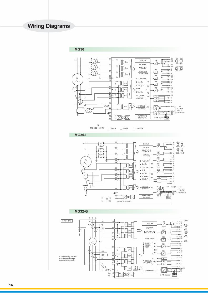
MG30
25
26
27
2839
29
3041
314232
43
33
44
12
13
G
1/5A
1/5A
1/5A
1/5A
1/5A
1/5A
1/5A
DISPLAY
MICROP.
R1
R2
R3
R4
R5
14
3
2
21
10
1122
79
81820
1946
5
1517
16
14
3
2
1
FUNZIONI
1>,Z<,Uo>
R1
R2
R3
R4
R5
12>,T>
Zc<, O>
U,f
W<, Ir>
IC, 60FL
B.I./B.F.
PROGR.
INT. FAULT
KEYB0ARDTASTIERA
FUNCTION
MG30
38(a)
37(b)
TO REXRELAY
EXPANSION2324
9 PIN MALE
S–S+
C
(21 – 22)
(10 – 11)
N.O.
N.O.
N.C.
N.C.
CE
MS-SCE 1629-R0 In=1A In=5A Un=100V
MG30
MD32-G
R = Stabilising resistorZ = Protection surge arrester (if required)
L/+
N/-
DISPLAY
MICROP.
MD32-G
FUNCTION
F187GF287GF87N
87G + 87N
A B C
I1A
I1B
I1C
G
25
26
27
28
39
29
30
41
31
4232
43
33
13
12
I2A
I2B
I2C
Z
R KEYBOARD
PROGR.
INT. FAULT
=˜˜
˜_
˜̃̃50-60
R5
R4
R3
R2
R1
R3
R2
R1
R4
R5
B3
B2
B1
9 PIN MALE
242334/38
1
2
3
14
16
1715
5
6419
2018
8
97
2211
1021
(21)
N.O.
N.C.
(10)
N.O.
N.C.
CS-S+
1/5A
1/5A
1/5A
1/5A
1/5A
1/5A
1/5A
MG30-I
G
In =
In =
13
12
33
43324231
41
30
29
3928
27
26
25
1A
5A MS-SCE1759-R0
DISPLAY
MICROP.
MG30-I
FUNZIONI
FUNCTION
I>, Z<, Io>
I2>, T>
IC, 60FL
B.I / B.F.
PROGR.
INT.FAULT
KEYBOARDTASTIERA
R1
R2
R3
R4
R5
R1
R2
R3
R4
R5
14
3
2
RS485
2110
1122
79
81820
19465
1517
18
14
3
21
37(b)
38(0)2324
TO REXRELAY
EXPANSION
(21 - 22)
N.O. N.C.
(10 - 11)
N.O. N.C.
1/5A
1/5A
1/5A
1/5A
Zc<, >
U, 1
w< Ir>+
cs-s+
Wiring Diagrams
16

••
Percentage Based Transformer Differential Relay
3 Phase Thermal + Over Current + Earth Fault Relay for transformer protection
Transformer Protection Relay
Salient Features
• Display of various parameters, trip count & trip data on 8 digit alphanumeric display
• Separate LEDs for individual fault indication
• Four user programmable output relays
• Built in self supervision & self testing feature help maintenance
• Easy operation by 5 push buttons
• RS485 Port for serial communication with “MSCOM” user friendly software
Description
Device Code
Design
Functions Available
Other Features
Burden on CT
Operating temp
Weight
Burden on Auxiliary supply
Output Contacts
Construction
Dim W x H x D in mm
Panel Cutout
Auxiliary Supply
3 Ph O/C, E/F + Thermal
0 0C
88-264 V AC / DC
250/51 RYBN, 49, 46, I t, 51BF,
50N/51N
Numeric
Lowset O/C
Highset O/C
Lowset E/F
Highset E/F
Thermal Overload
Lowset current unbalance with
Definite / Inverse time tripping
Highset current unbalance
Inrush Energy protection
CB Failure function
Blocking function
Display of Parameters
Built in self supervision
RS485 Port
1 A OR 5 A site selectable
0.2 VA for 5 A, 0.01 VA for 1 A
10 to 60 C
< 2kg
8.5 VA
5 C/O, S/R or H/R or Time del
Draw out
121 x 158 x 224
113 x 142
20-110 V AC / DC
Transformer Differential +
Restricted E/F
0 0C
87 RYB, 87N
Numeric
Lowset Differential
Lowset Op time : <=30mS
Highset Differential
Highset Op time : 6-20mS
Restricted Earth Fault
Dual slope Bias
Highset can be Biased / Unbiased
2nd harmonic restraint setting
5th harmonic restraint setting
Auto correction of CT Ratio
Zero sequence compensation
Blocking Function
Display of parameters
Built in self supervision
RS485 Port
1 A OR 5 A site selectable
Waveform capture feature
0.2 VA for 5 A, 0.01 VA for 1 A
10 to 60 C
< 2kg
8.5 VA
5 C/O, S/R or H/R or Time del
Draw out
121 x 158 x 224
113 x 142
20-110 V AC / DC
88-264 V AC / DC
Transformer Differential
0 0C
87 RYB
Numeric
Lowset Differential
Lowset Op time : <=30mS
Highset Differential
Highset Op time : 6-20mS
Dual slope Bias
Highset can be Biased / Unbiased
2nd harmonic restraint setting
5th harmonic restraint setting
Auto correction of CT Ratio
Zero sequence compensation
Blocking Function
Display of parameters
Built in self supervision
RS485 Port
1 A OR 5 A site selectable
Waveform capture feature
0.2 VA for 5 A, 0.01 VA for 1 A
10 to 60 C
< 2kg
8.5 VA
5 C/O, S/R or H/R or Time del
Draw out
121 x 158 x 224
113 x 142
20-110 V AC / DC
88-264 V AC / DC
Model MD32T MD32TM IM30T
Ordering Information
17

MD32T / MD32TM
MD32T
R = Stabilising resistorZ = Protection surgearrester (if required)
L/+
N/-
˜
IEC 255 ˜˜
=
˜̃
˜
87T + 87N
A B C
In1
I1A
I1B
I1C
25
26
27
28
39V1
V2
Kv =V1
V2
29
I2A
I2B
I2C
3041
31423243
Z
33
12
13
R 50-60
1/5A
1/5A
1/5A
1/5A
KEYBOARD
PROGR.INT. FAULT
R5
R4
R3
R2
R1F187TF287TF87N
FUNCTION
MICROP.
DISPLAYR1
R2
R3
R4
R5
B3
B2
B1
9 PIN MALE
CS-S+
242334/38
1
2
3
14
16
1715
5
6419
2018
8
972211
1021
(21)
N.O.
N.O.
N.C.
N.C.
(10)
V1
V2á
IM30T
IM30T
L/+
N/-
1/5A
1/5A
1/5A
1/5A
A B C A B C A B C
25
26
27
28
39
29
41
303243
31
42
33
25
26
27
28
39
29
41
303243
31
42
33
25
26
27
28
39
29
41
303243
31
42
33
˜
˜̃˜
˜˜
=
_
44
12
13
In = 5A In = 1A
PRESA/TAP 31 Ion = 5APRESA/TAP 33 Ion = 1A
KEYBOARD
PROGR.INT.FAULT
R5
R4
R3
R2
R1
R3
R4
R5
R2
R1
F46
2I t = KF51BFF51NF50NF51F50F49
FUNCTION
MICROP.
DISPLAY
RT
BIO
BIF
CS-S+
9 PIN MALE
242334/38
1
2
3
14
16
17155
64
19
2018
8
97
2211
1021
(21)
N.O.
N.O.
N.C.
N.C.
(10)
IEC 255
BT 2 50
1/5A
1/5A
1/5A
Wiring Diagrams
18

••
3 Phase O/C & E/F relay with Highset + Auto Reclosure (Optional)
3 Phase Directional O/C & E/F relay with Highset
Salient Features
RS485 Port for serial communication with “MSCOM” user friendly software
• Display of various parameters, trip count & trip data on LCD screen
• Separate LEDs for various fault indication
• Built in self supervision & self testing feature
• Wave form capturing •
• Front RS232 Port for local programming
Feeder Protection Relays
Model MC30MC20
3P O/C + E/F + Highset + Autoreclosing (Optional)51, 51N, 50, 50N, 51BF, 79 (optional)NumericLowset O/C2 Highset O/C LevelsLowset E/F2 Highset E/F LevelsTime current curves selectable accordingto IEC/IEEE standardsAuto Reclose (In MC20-R)Breaker Failure protectionCircuit Breaker control via serial portBlocking Output and Blocking Input for pilotwire selectivity coordinationTime tagged multiple event recordingOscillographic wave form captureAccepts 3 Digital inputsDisplay LCD 16 (2 x 8) characters3rd Harmonic Filter on the neutral input currentPassword protection facility1 A or 5 A site selectableDisplay of parametersBuilt in supervisionModbus RTU / IEC870-5-103 Communication ProtocolsFront RS232 Port for Local ProgrammingOscillographic recording of input QuantitiesRS485 serial communication port on Back Panel0.1 VA for 1 A, 0.3 VA for 5 ANA< 7 VA
4 C/O ContactsDrawout83 x 164 x 22564 x 137
24-110 V AC/DC 88-264 V AC/DC
0 0-10 C to 55 C< 1.5Kg
3P O/C + E/F + Highset 51, 51N, 50, 50N, 49, 51BFNumericLowset O/C2 Highset O/C LevelsLowset E/F2 Highset E/F LevelsThermal imageBreaker Failure protection Circuit Breaker control via Serial port Blocking Output and Blocking Input for pilotWire selectivity coordinationTime tagged multiple event recordingOscillographic wave form captureAccepts 3 Digital inputsDisplay LCD 16 (2 x 8) charactersT
Password protection facility
1 A or 5 A site selectableDisplay of parametersBuilt in supervisionModbus RTU / IEC870-5-103 Communication ProtocolsFront RS232 Port for Local ProgrammingOscillographic recording of input QuantitiesRS485 serial communication port on Back Panel0.1 VA for 1 A, 0.3 VA for 5 ANA< 7 VA
4 C/O ContactsDrawout83 x 164 x 22564 x 137
24-110 V AC/DC 88-264 V AC/DC
ime current curves selectable accordingto IEC/IEEE standards
0 0-10 C to 55 C< 1.5Kg
DescriptionDevice CodeDesignFunctions Available
RatingOther Features
Burden on CTBurden on PTBurden on Aux. SupplyOperating TempWeightOutput ContactsConstructionDimPanel Cutout
Aux. Supply Type 1 Type 2
Ordering Information
19
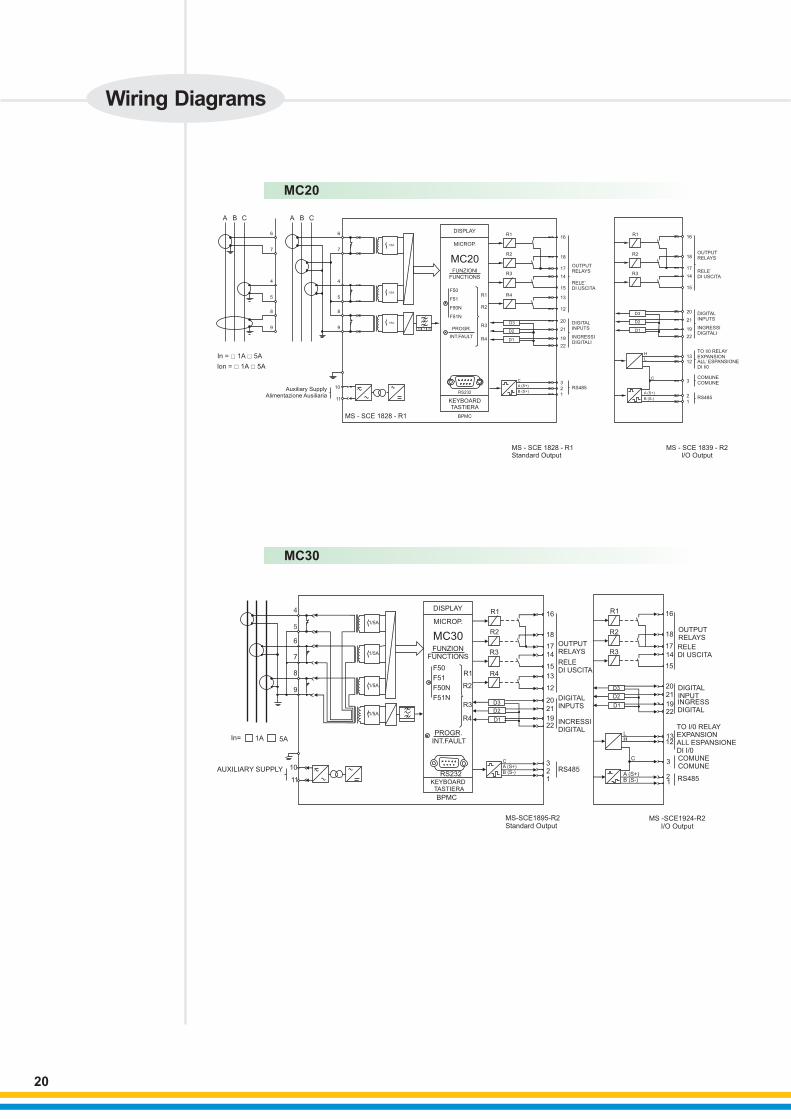
MC20
MC30
1/5A
1/5A
1/5A
1/5A
4
5
6
7
8
9
In=
F50
F51
F50N
F51N
PROGR.INT.FAULT
R1
R2
R3
R4
R1
R2
R3
R4
D3
D2
D1
RS232KEYBOARD TASTIERA
10
11
BPMC
16
18
17
14
15
13
12
20
21
1922
OUTPUTRELAYS
RELEDI USCITA
DIGITALINPUTS
INCRESSIDIGITAL
321
RS485
MS-SCE1895-R2Standard Output
MS -SCE1924-R2I/O Output
DIGITALINPUTINGRESSDIGITAL
TO I/0 RELAYEXPANSIONALL ESPANSIONEDI I/0COMUNECOMUNE
RS485
R1
R2
R3
D3
D2
D1
OUTPUTRELAYS
RELEDI USCITA
CA (S+)B (S-)
LH
C
A (S+)B (S-)
16
18
17
14
15
20
19
21
22
1312
3
21
AUXILIARY SUPPLY
5A1A
DISPLAY
MICROP.
MC30FUNZION
FUNCTIONS
BT 2
MS - SCE 1828 - R1
1/5A
1/5A
1/5A
6
7
4
5
8
9
6
7
4
5
8
9
In = □ 1A □ 5A
lon = □ 1A □ 5A
Auxiliary SupplyAlimentazione Ausiliaria
10
11
BPMC
KEYBOARDTASTIERA
RS232
PROGR.
INT.FAULTR4
R3
R2
R1F50
F51
F50N
F51N
FUNZIONI
FUNCTIONS
MC20
MICROP.
DISPLAY
R4
R3
R2
R1
D1
D2
D3
16
18
17
14
15
13
12
20
21
19
22
3
2
1
RS485
DIGITALINPUTS
INGRESSIDIGITALI
RELE’DI USCITA
OUTPUTRELAYS
R3
R2
R116
18
17
14
15
RELE’DI USCITA
OUTPUTRELAYS
20
21
19
22
1312
3
2
1
DIGITALINPUTS
INGRESSIDIGITALI
RS485
COMUNECOMUNE
TO I/0 RELAYEXPANSIONALL’ ESPANSIONEDI I/0
MS - SCE 1828 - R1Standard Output
MS - SCE 1839 - R2I/O Output
D3
D1
D2
H
L
C
A (S+)
B (S-)
C
A (S+)
B (S+)
50
A B C A B C
Wiring Diagrams
20
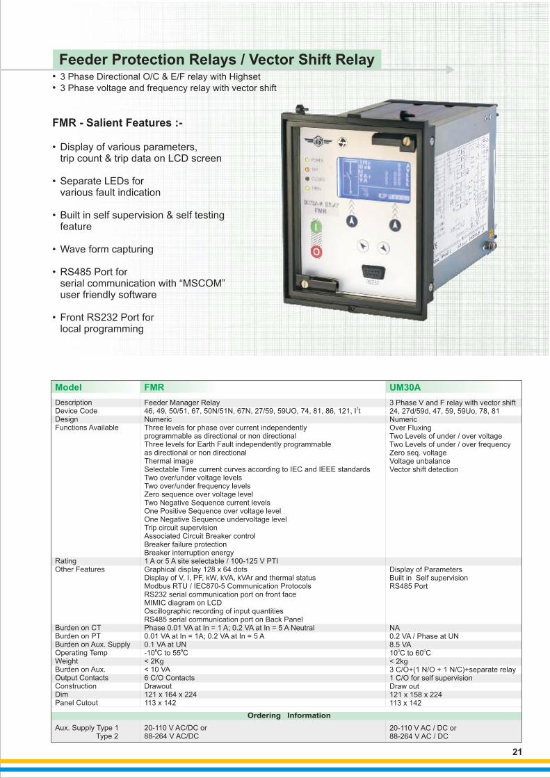
3 Phase Directional O/C & E/F relay with Highset
3 Phase voltage and frequency relay with vector shift
••
FMR - Salient Features :-
RS485 Port for serial communication with “MSCOM” user friendly software
• Display of various parameters, trip count & trip data on LCD screen
• Separate LEDs for various fault indication
• Built in self supervision & self testing feature
• Wave form capturing •
• Front RS232 Port for local programming
Feeder Protection Relays / Vector Shift Relay
Model FMR
DescriptionDevice CodeDesignFunctions Available
RatingOther Features
Burden on CTBurden on PTBurden on Aux. SupplyOperating TempWeightBurden on Aux.Output ContactsConstructionDimPanel Cutout
Aux. Supply Type 1 Type 2
Feeder Manager Relay2
46, 49, 50/51, 67, 50N/51N, 67N, 27/59, 59UO, 74, 81, 86, 121, I tNumericThree levels for phase over current independentlyprogrammable as directional or non directionalThree levels for Earth Fault independently programmableas directional or non directionalThermal imageSelectable Time current curves according to IEC and IEEE standardsTwo over/under voltage levelsTwo over/under frequency levelsZero sequence over voltage levelTwo Negative Sequence current levelsOne Positive Sequence over voltage levelOne Negative Sequence undervoltage levelTrip circuit supervisionAssociated Circuit Breaker controlBreaker failure protectionBreaker interruption energy1 A or 5 A site selectable / 100-125 V PTIGraphical display 128 x 64 dotsDisplay of V, I, PF, kW, kVA, kVAr and thermal statusModbus RTU / IEC870-5 Communication ProtocolsRS232 serial communication port on front faceMIMIC diagram on LCDOscillographic recording of input quantitiesRS485 serial communication port on Back PanelPhase 0.01 VA at In = 1 A; 0.2 VA at In = 5 A Neutral0.01 VA at In = 1A; 0.2 VA at In = 5 A0.1 VA at UN
6 C/O ContactsDrawout121 x 164 x 224113 x 142
20-110 V AC/DC or 88-264 V AC/DC
0 0-10 C to 55 C< 2Kg< 10 VA
3 Phase V and F relay with vector shift24, 27d/59d, 47, 59, 59Uo, 78, 81
0C
NumericOver FluxingTwo Levels of under / over voltageTwo Levels of under / over frequencyZero seq. voltageVoltage unbalanceVector shift detection
Display of ParametersBuilt in Self supervisionRS485 Port
NA0.2 VA / Phase at UN8.5 VA
010 to 60 C< 2kg3 C/O+(1 N/O + 1 N/C)+separate relay1 C/O for self supervisionDraw out121 x 158 x 224113 x 142
20-110 V AC / DC or88-264 V AC / DC
UM30A
Ordering Information
21

FMR
A B C A B C2
3
4
5
6
7
8
9
41
42
43
44
45
46
47
48
2
3
4
5
6
7
8
9
41
42
43
44
45
46
47
48
ULTRA
Feeder
Manager
Relay
POWER
TRIP
ON
OFF
11
21
R1
R2
R3
R4
R5
R6
R1
R2
R3
R4
R5
R6
D1
D2
D3
D4
+-
HL
ON
2528
15
25
14
2435
34
33
32
15
2231
12
25
15
25
19
38
2717
16
3437
In = □ 1A □ 5A lon = □ 1A □ 5A
MS - SCE 1844-R3
Auxiliary SupplyAlimentazione Ausiliaria
Un = 230Vac MAX.
BPUFRONT-RS252
DIGITALINPUTS
INGRESSIDIGITALI
N.C
N.O
(25)
TripOxi. sup.
UM30A
A
B
C
EA
UC UA
UBEBEC
13
12
44
3041
293928
27
26
25
IEC 255
24(-20%) - 110(+20%)Vac 24(-20%) - 125(+20%)Vdc 80(-20%) - 220(+20%)Vac 90(-20%) - 250(+20%)Vdc
_
˜˜
˜ =
Uo ˜̃̃BT 2 50
DISPLAY
MICROP.
FUNCTION
F27 / 59
F27d / 59d
F59s
F59U
F81
F59 / 81
PROGR.
INT. FAULT
KEYBOARD
R1
R2
R3
R4
R4
R3
R5
R5
R1
R2
2110
112279
81820
1946
51517
161432134/382324
(21)
N.O.
N.O.
N.C.
N.C.
(10)
14
BI<
BI>
CS-S+
9 PIN MALE
UM30A
L/+
N/-
Wiring Diagrams
22
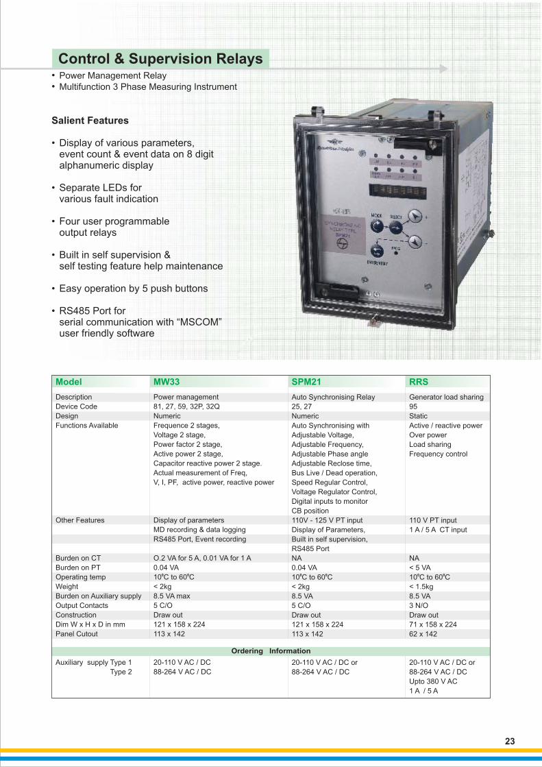
Salient Features
• Display of various parameters, event count & event data on 8 digit alphanumeric display
• Separate LEDs for various fault indication
• Four user programmable output relays
• Built in self supervision & self testing feature help maintenance
• Easy operation by 5 push buttons
• RS485 Port for serial communication with “MSCOM” user friendly software
Control & Supervision Relays••
Power Management Relay
Multifunction 3 Phase Measuring Instrument
Description
Device Code
Design
Functions Available
Other Features
Burden on CT
Burden on PT
Operating temp
Weight
Burden on Auxiliary supply
Output Contacts
Construction
Dim W x H x D in mm
Panel Cutout
Auxiliary supply Type 1
Type 2
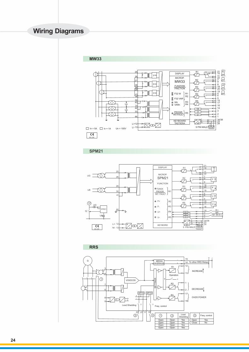
Power management
0 0
81, 27, 59, 32P, 32Q
Numeric
Frequence 2 stages,
Voltage 2 stage,
Power factor 2 stage,
Active power 2 stage,
Capacitor reactive power 2 stage.
Actual measurement of Freq,
V, I, PF, active power, reactive power
Display of parameters
MD recording & data logging
RS485 Port, Event recording
O.2 VA for 5 A, 0.01 VA for 1 A
0.04 VA
10 C to 60 C
< 2kg
8.5 VA max
5 C/O
Draw out
121 x 158 x 224
113 x 142
20-110 V AC / DC
88-264 V AC / DC
Model MW33 SPM21
Auto Synchronising Relay
25, 27
Numeric
Auto Synchronising with
Adjustable Voltage,
Adjustable Frequency,
Adjustable Phase angle
Adjustable Reclose time,
Bus Live / Dead operation,
Speed Regular Control,
Voltage Regulator Control,
Digital inputs to monitor
CB position
110V - 125 V PT input
Display of Parameters,
Built in self supervision,
RS485 Port
NA
0.04 VA
10 to 60
< 2kg
8.5 VA
5 C/O
Draw out
121 x 158 x 224
113 x 142
20-110 V AC / DC or
88-264 V AC / DC
0 0C C
RRS
Generator load sharing
95
Static
Active / reactive power
Over power
Load sharing
Frequency control
110 V PT input
1 A / 5 A CT input
NA
< 5 VA
10 C to 60 C
< 1.5kg
8.5 VA
3 N/O
Draw out
71 x 158 x 224
62 x 142
20-110 V AC / DC or
88-264 V AC / DC
Upto 380 V AC
1 A / 5 A
0 0
Ordering Information
23
G
1 T
OPTO OPTO
VOIOCOS
Lood Shedding
SE
TT
ING
S
MEDIAAVERAGE
Operation
To other RRS Relays
INCREASE
DECREASE
OVER POWER
Freq. control
Open
Open
Open
Open Open
Open
Open
Open
Lood Shedding
Yes
Yes
Yes
Yes
Open Yes
Close No
Freq. control
11
1
10
2 3 32
22 21
3
4
7
6
8
9
R1
R2
R3
15
12
13
1
2
17
18
14
(.) (.)
- -
+
+
+
+
-
-
-+
RRS
SPM21
DISPLAY
MICROP.
SPM21
FUNCTION
F25SX
R1
R2
R3
R4
R5
PROGR.
INT. FAULT
9 PIN MALE
CS-S+
2110
1122
9
8
1820
19
46
1517
16
143
21
34/382324KEYBORD
R5
R4
R3
R2
R1
F+
F-
U+
U-
5
7
BX
BR
SX
B.I.
BR52 (N.O.)
U
52 C
SPM21
UG
UB
G1
52
UB
L/+
N/-
12
13
44
41
30
29
26
25
UG
U
F
F
IEC 255
MW33
L/+
L/-
1/5A
1/5A
1/5A
25
26
27
283929
4130
3243
3142
33
Un
Un
44
12
13In = 5A In = 1A Un = 100V
_
=˜˜
˜KEYBOARDTASTIERA
PROGR.INT.FAULT
R5
DISPLAY
MICROP.
MW33FUNZIONIFINCTION
F32 W
F32 VAR
WhVARh
R1
R2
R3R4
R5
R4
R3
R2
R1
14
3
2
CS-S+
9 PIN MALE
242334/38
1
2
3
14
16
17155
6419
20188
972211
1021
(21)
N.O.
N.C.
(10)
N.O.
N.C.
IEC 255
Wiring Diagrams
24

Voltage and Frequency Relays••
3 Phase Volt ge and frequency relay with df/dt & dv/dt 1 Phase Voltage and frequency relay
a
Salient Features
•
•
•
•
•
Display of various parameters, tripcount & trip data on LCD screen
Separate LEDs for individual fault indication
Built in self supervision & self testing feature
RS485 port for serial communication with “MSCOM” software
Easy operation by push buttons
Description
Device CodeDesignFunctions Available
RatingOther Features
Burden on CTBurden on PTOperating tempWeightBurden onA uxiliaryOutput Contacts
ConstructionDim W x H x D in mmPanel Cutout
Auxiliary Supply
Model UFD34 MC1V MC3V
3 Ph Volt ge and Frequency Relay81, 27, 59, df/dt, dv/dtNumericSelectable 4 stages of frequency as Under/Over frequencySelectable 2 stages of voltage as Under/Over voltageSelectable 2 stages of df/dtSelectable 1 stages of de/dtBlocking Output and Blocking InputTime tagged multiple event recording
100-125 VDisplay of parametersBuilt in self supervisionOscillogarphic recording of input quantitiesRS485 serial communication port on Back Panel
Not Applicable0.04 VA
0 0-10 C to 60 C< 2.5Kg8.5 VA4 C/O Contacts + 1 C/O for Self supervisionDrawout121 x 164 x 224113 x 142
20-110 V AC/DC or88-264 V AC/DC
a Single phase Volt ge and Frequency Relay27, 59, 81NumericTwo Under Voltage elementsTwo Over Voltage elementsOne UnderFrequency elementOne OverFrequency elementBlocking Output and Blocking InputTime tagged multiple event recordingOscillogarphic wave form captureDisplay LCD 16 (2 x 8) characters
100-125 VDisplay of parametersBuilt inSelf supervisionModbus RTU / IEC870-5-103 Communication ProtocolsFront RS232 Port for Local ProgrammingOscillogarphic recording of input quantitiesRS485 serial comunication port on Back Panel0.1 VA for 1 A, 0.3 VA for 5 ANA
0 0-10 C to 55 C< 1.5Kg< 7 VA4 C/O Contacts + 1 C/O for Self supervisionDrawout83 x 164 x 22464 x 137
20-110 V AC/DC or88-264 V AC/DC
a 3 Ph Volt ge and Frequency Relay27, 59, 47, 59 V 0, 81NumericTwo Under Voltage elementsTwo Over Voltage elementsOne Under Frequency elementOne Over Frequency elementOne Zero Sequence Over Voltage ElementOne Negative Sequence Under Voltage ElementOne Positive Sequence Over Voltage ElementOscillographic wave form captureModbus RTU / IEC870-5-103Communication ProtocolsDisplay LCD 16 (2 x 8) characters
100-125 VDisplay of parametersBuilt in self supervisionModbus RTU / IEC870-5-103 Communication ProtocolsFront RS232 Port for Local ProgrammingOscillogarphic recording of input quantitiesRS485 serial communication port on Back Panel0.1 VA for 1 A, 0.3 VA for 5 ANA
0 0-10 C to 55 C< 1.5Kg< 7 VA4 C/O Contacts + 1 C/O for Self supervisionDrawout83 x 164 x 22464 x 137
20-110 V AC/DC or88-264 V AC/DC
a
Ordering Information
25
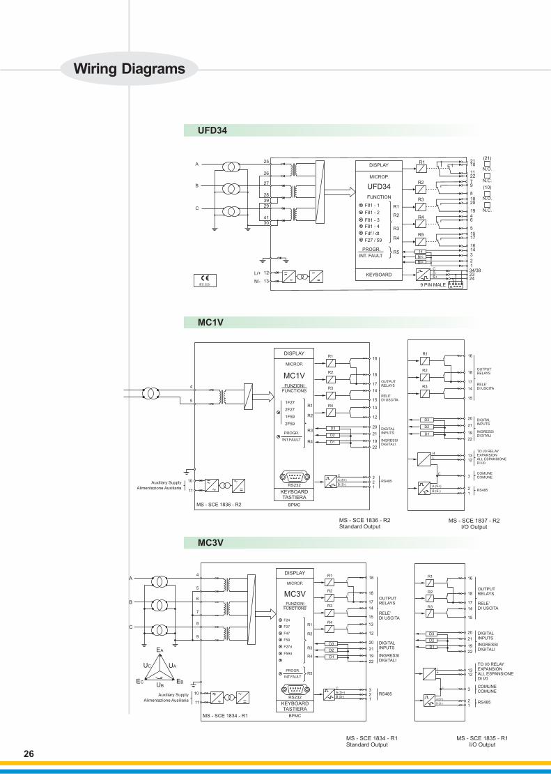
UFD34
L/+
N/-
UFD34
A
B
C
25
26
27
28
39
29
4130
12
13IEC 255
_
˜˜
˜=
KEYBOARD
PROGR.
INT. FAULTR5
R4
R3
R5
R4
R3
R2
R1
R2
R1DISPLAY
MICROP.
FUNCTION
F81 - 1
F81 - 2
F81 - 3
F81 - 4
Fdf / dt
F27 / 59
14
BI<
BI>
CS-S+
9 PIN MALE
242334/3812
31416
1715
5
6419
2018
8
972211
1021
(21)
N.O.
N.C.
(10)
N.O.
N.C.
BPMC
KEYBOARDTASTIERA
RS232
PROGR.
INT.FAULTR4
R3
R2
R11F27
FUNZIONI
FUNCTIONS
MC1V
MICROP.
DISPLAY
R4
R3
R2
R1
D1
D2
D3
16
18
17
14
15
13
12
20
21
19
22
3
2
1
DIGITALINPUTS
INGRESSIDIGITALI
RELE’DI USCITA
OUTPUTRELAYS
C
A (S+)
B (S-)
R3
R2
R116
18
17
14
15
RELE’DI USCITA
OUTPUTRELAYS
20
21
19
22
1312
3
2
1
DIGITALINPUTS
INGRESSIDIGITALI
RS485
COMUNECOMUNE
TO I/0 RELAYEXPANSIONALL ESPANSIONEDI I/0
D3
D1
D2
H
L
C
A (S+)
B (S-)
RS485
2F27
1F59
2F59
Auxiliary Supply
Alimentazione Ausiliaria
MS - SCE 1836 - R2
MS - SCE 1837 - R2I/O Output
MS - SCE 1836 - R2Standard Output
4
5
10
11
MC1V
BPMC
KEYBOARDTASTIERA
RS232
PROGR.
INT.FAULT
R4
R3
R2
R1
F24
F27
F47
F59
F27d
F59d
FUNZIONI
FUNCTIONS
MC3V
MICROP.
DISPLAY
R4
R3
R2
R1
D1
D2
D3
16
18
17
14
15
13
12
20
21
19
22
321
DIGITALINPUTS
INGRESSIDIGITALI
RELE’DI USCITA
OUTPUTRELAYS
C
A (S+)
B (S-)RS485
R5
R3
R2
R1 16
18
17
14
15
RELE’DI USCITA
OUTPUTRELAYS
20
21
19
22
1312
3
21
DIGITALINPUTS
INGRESSIDIGITALI
RS485
COMUNECOMUNE
TO I/0 RELAYEXPANSIONALL ESPANSIONEDI I/0
D3
D1
D2
H
L
C
A (S+)
B (S-)
4
5
6
7
8
9
A
B
C
EA
UAUC
UBEBEC
10
11
Auxiliary Supply
Alimentazione Ausiliaria
MS - SCE 1834 - R1
MS - SCE 1834 - R1Standard Output
MS - SCE 1835 - R1I/O Output
MC3V
Wiring Diagrams
26
27
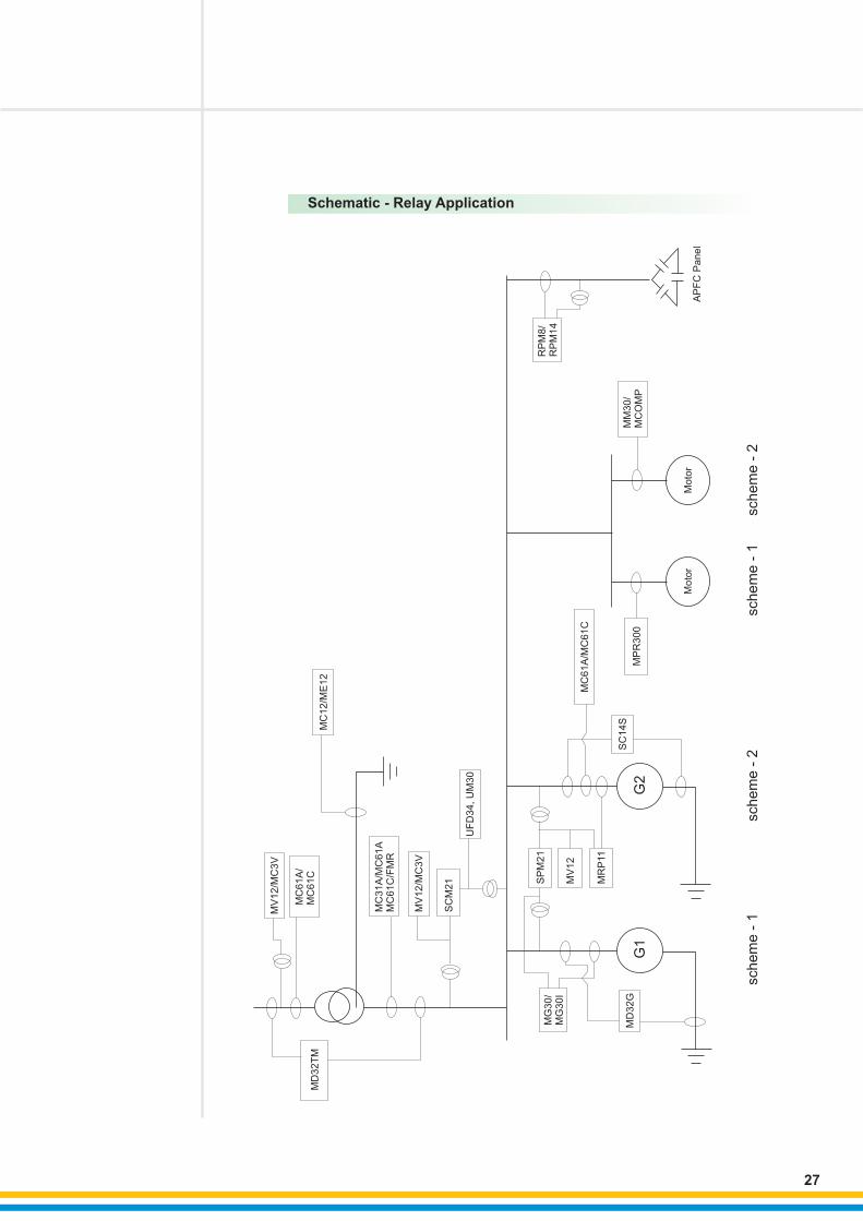
Schematic - Relay Application
MV
12
/MC
3V
MC
61
A/
MC
61
C
MC
12
/ME
12
MD
32
TM
MC
31
A/
MC
61
C/F
MR
MC
61
A
MV
12
/MC
3V
SC
M2
1
UF
D3
4, U
M3
0
MG
30
/M
G3
0I
SP
M2
1
MV
12
MR
P11
MD
32
GS
C1
4S
MP
R3
00
G1
G2
Mo
tor
Mo
tor
MM
30
/M
CO
MP
RP
M8
/R
PM
14
AP
FC
Pa
ne
l
schem
e -
1
MC
61
A/M
C6
1C
sch
em
e -
2sch
em
e -
1sch
em
e -
2

REGISTERED OFFICE AND HEAD OFFICEL&T House, Ballard EstateP. O. Box 278Mumbai 400 001Tel: 022-67525656Fax: 022-67525858Website: www.Larsentoubro.com
ELECTRICAL STANDARD PRODUCTS (ESP)501, Sakar Complex I Opp. Gandhigram Rly. Station Ashram RoadAhmedabad 380 009Tel: 079-66304006-11Fax: 079-66304025e-mail: [email protected]
38, Cubbon Road, P. O. Box 5098Bangalore 560 001Tel: 080-25020100 / 25020324Fax: 080-25580525e-mail: [email protected]
131/1, Zone IIMaharana Pratap NagarBhopal 462 011Tel: 0755-4098721 / 7 / 8 / 9Fax: 0755-2769264e-mail: [email protected]
Plot No. 559, Annapurna ComplexLewis RoadBhubaneswar 751 014Tel: 0674-6451342, 2436696Fax: 0674-2537309e-mail: [email protected]
SCO 32, Sector 26-D Madhya Marg, P. O. Box 14Chandigarh 160 026Tel: 0172-4646840, 4646853Fax: 0172-4646802e-mail: [email protected]
10, Club House Road, Annasalai Chennai 600 002Tel: 044-28462072 / 4 / 5 / 2109Fax: 044-28462102 / 3 e-mail: [email protected]
67, Appuswamy RoadPost Bag 7156 Opp. Nirmala CollegeCoimbatore 641 045Tel: 0422-2588120 / 1 / 5Fax: 0422-2588148e-mail: [email protected]
Electrical Standard Products (ESP) Branch Offices:
L&T House, Group MIG-5 PadmanabhpurDurg 491 001Tel: 0788-2213833 / 14 / 21 / 29Fax: 0788-2213820e-mail: [email protected]
Khairasol, Degaul AvenueDurgapur 713 212Tel: 2559848, 2559849, 2559844Fax: 0343-2553614e-mail: [email protected]
Milanpur Road, Bamuni MaidanGuwahati 781 021Tel: 0361-2550562 / 65Fax: 0361-2551308e-mail: [email protected]
II Floor, Vasantha Chambers5-10-173, Fateh Maidan RoadHyderabad 500 004Tel: 040-67015052Fax: 040-23296468e-mail: [email protected]
Monarch Building, 1st FloorD-236 & 237, Amrapali RoadVaishali NagarJaipur 302 021Tel: 0141-4385914 / 18Fax: 0141-4385925e-mail: [email protected]
Akashdeep Plaza, 2nd FloorP. O. GolmuriJamshedpur 831 003JharkhandTel: 0657-2312205 / 38Fax: 0657-2341250e-mail: [email protected]
Skybright Bldg; M. G. RoadRavipuram Junction, ErnakulamKochi 682 016Tel: 0484-4409420 / 4 / 5 / 7Fax: 0484-4409426e-mail: [email protected]
3-B, Shakespeare SaraniKolkata 700 071Tel: 033-44002572 / 3 / 4 Fax: 033-22821025 / 7587e-mail: [email protected]
A28, Indira Nagar, Faizabad Road Lucknow 226 016Tel: 0522-2312904 / 5 / 6Fax: 0522-2311671e-mail: [email protected]
No: 73, Karpaga Nagar, 8th StreetK. PudurMadurai 625 007Tel: 0452-2537404, 2521068Fax: 0452-2537552e-mail: [email protected]
EBG North Wing Office-Level 2 Gate 7, Powai CampusMumbai 400 072Tel: 022-67052874 / 2737 / 1156Fax: 022-67051112e-mail: [email protected]
12, Shivaji NagarNorth Ambazari RoadNagpur 440 010Tel: 0712-2260012 / 3Fax: 0712-2260020 / 30e-mail: [email protected]
32, Shivaji Marg P. O. Box 6223New Delhi 110 015Tel: 011-41419514 / 5 / 6Fax: 011-41419600e-mail: [email protected]
L&T House P. O. Box 119 191/1, Dhole Patil RoadPune 411 001Tel: 020-26135048 / 26164048Fax: 020-26124910, 26135048e-mail: [email protected]
3rd Floor Vishwakarma ChambersMajura Gate, Ring RoadSurat 395 002Tel: 0261-2473726Fax: 0261-2477078e-mail: [email protected]
Radhadaya ComplexOld Padra RoadNear Charotar SocietyVadodara 390 007Tel: 0265-6613610 / 1 / 2Fax: 0265-2336184e-mail: [email protected]
48-8-16, DwarakanagarVisakhapatnam 530 016Tel: 0891-6620411-2 / 3Fax: 0891-6620416e-mail: [email protected]
Product improvement is a continuous process. For the latest information and special applications, please contact any of our offices listed here.
Larsen & Toubro Limited Electrical Standard ProductsPowai Campus, Mumbai 400 072Customer Interaction Center (CIC)BSNL / MTNL (toll free) : 1800 233 5858Reliance (toll free) : 1800 200 5858Tel : 022 6774 5858, Fax : 022 6774 5859E-mail : [email protected] Website : www.LNTEBG.com
SP 50297-R1 090712