sequence component applications in protective relays
TRANSCRIPT
Sequence Component Applications in Protective Relays –
Advantages, Limitations, and Solutions
Bogdan Kasztenny, Mangapathirao V. Mynam, and Normann Fischer Schweitzer Engineering Laboratories, Inc.
Presented at the 46th Annual Western Protective Relay Conference
Spokane, Washington October 22–24, 2019
Previously presented at the 73rd Annual Georgia Tech Protective Relaying Conference, May 2019
Originally presented at the 72nd Annual Conference for Protective Relay Engineers, March 2019

1
Sequence Component Applications in Protective Relays –
Advantages, Limitations, and Solutions Bogdan Kasztenny, Mangapathirao V. Mynam, and Normann Fischer,
Schweitzer Engineering Laboratories, Inc.
Abstract—Negative- and zero-sequence voltages and currents are powerful measurements aiding fault type identification, fault direction identification, and fault discrimination in general. Not influenced by load, they contribute to protection speed and sensitivity. However, sequence components are present for a range of conditions, not only faults: open pole, load and line unbalance, breaker pole scatter, and current transformer ratio errors and saturation, to name a few. New power system sources, such as wind generators and inverters, supply sequence components differently than traditional generators. This paper is a tutorial on various protection applications of sequence components, focusing on advantages, limitations, and application considerations.
I. INTRODUCTION In 1918, Charles Legeyt Fortescue introduced us to the
concept of “symmetrical coordinates” [1] as a way of solving three-phase circuits for unbalanced steady-state conditions. In the precomputer era, symmetrical components, or sequence components as we know them today, played a fundamental role in analysis and design of three-phase networks and their building blocks.
Very early, protection engineers realized the many interesting and useful characteristics of the sequence components and networks that allowed new operating principles for protective relays. In many instances, measuring and responding to sequence voltages and currents yielded a far better relay performance than measuring and responding to phase voltages and currents. Soon, sequence components became one of the foundational principles of protective relaying, in addition to being a mere analysis tool for faults and open-phase conditions.
This paper reviews sequence components and their applications in power system analysis and protection.
Section II summarizes the mathematical foundations for sequence components. It explains their physical meaning and their original purpose of substituting the phase coordinates with symmetrical coordinates when solving three-phase networks for unbalanced conditions.
Section III summarizes the foundations of sequence networks and the basic rules of representing various power apparatuses by their equivalent sequence network models.
Section IV explains how sequence components and networks are used for solving three-phase networks for unbalanced steady-state conditions.
Section V reviews the many interesting properties of sequence components that laid the foundation for a range of protection principles and continue to provide new ideas and applications.
Section VI reviews the most common protection principles that heavily rely on sequence components, such as directional elements, fault type identification logic, sequence differential elements, time-coordinated ground fault protection, distance element polarizing, and fault locating.
Concerned with protection security, Section VII reviews various sources of sequence components beyond just short circuits. These include current transformer (CT) errors, asymmetrical operation of series capacitors, breaker pole scatter, and filter transients.
Section VIII briefly compares sequence components with incremental quantities to emphasize their similarities and differences, relative strengths and weaknesses, and complementary nature.
Section IX reviews several application considerations for protection elements and schemes that heavily rely on sequence components. These range from securing sequence elements for CT errors to applications near nontraditional sources such as inverter-based solar farms and wind generators.
For brevity, through the paper we often refer to the negative- and zero-sequence components or elements as just sequence components or elements. This is because most of our discussion concerns unbalanced conditions, relegating the positive-sequence components to the background of our discussion.
II. SEQUENCE COMPONENTS In power system engineering, we are interested in
calculating or measuring voltages and currents at a point of interest in a three-phase network, such as at a protective relay location. The signals we measure are the phase voltages (vA, vB, and vC) available from voltage transformers (VTs) and the phase currents (iA, iB, and iC) available from CTs.
Under steady-state balanced conditions, the phase voltages are of equal magnitudes and are equally spaced, following one another every 120 electrical degrees (120°). The same applies to the steady-state balanced currents. Because of this symmetry, it is easy and convenient to solve three-phase networks in steady-state balanced conditions, such as when performing
2
load-flow calculations. When the network is not balanced, however, such as during a short circuit or an open-phase condition, the network analysis becomes more complicated.
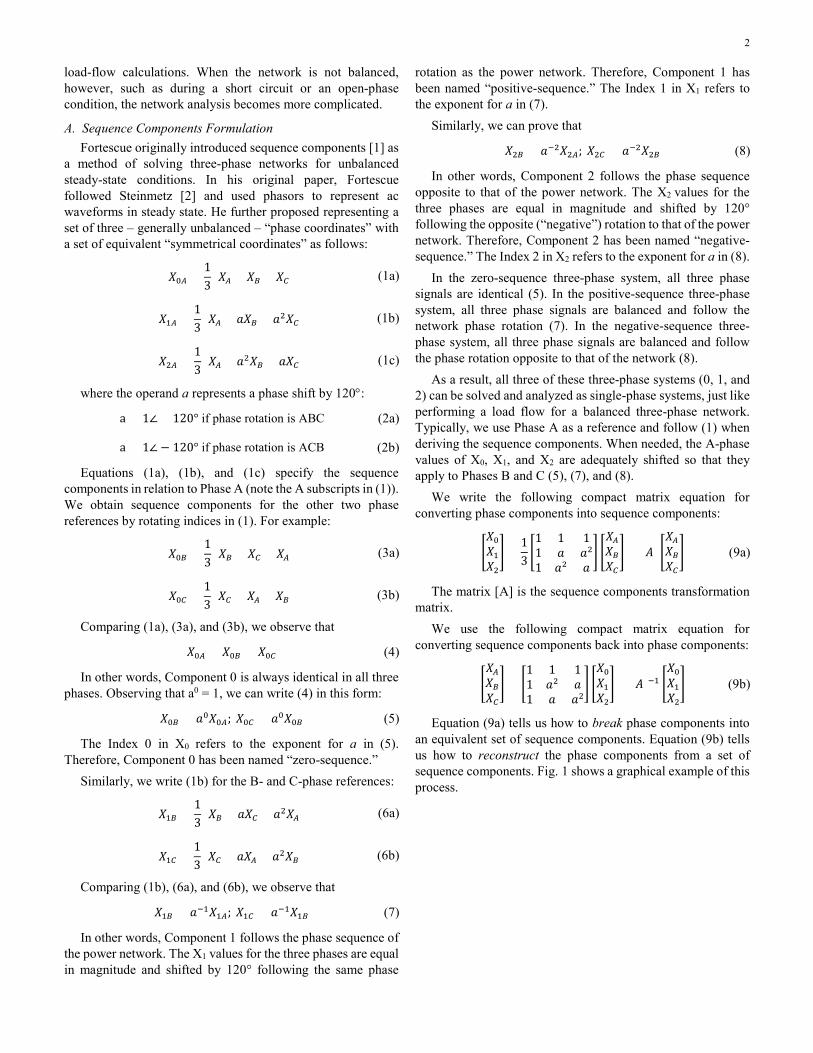
A. Sequence Components Formulation Fortescue originally introduced sequence components [1] as
a method of solving three-phase networks for unbalanced steady-state conditions. In his original paper, Fortescue followed Steinmetz [2] and used phasors to represent ac waveforms in steady state. He further proposed representing a set of three – generally unbalanced – “phase coordinates” with a set of equivalent “symmetrical coordinates” as follows:
𝑋𝑋0𝐴𝐴 =13
(𝑋𝑋𝐴𝐴 + 𝑋𝑋𝐵𝐵 + 𝑋𝑋𝐶𝐶) (1a)
𝑋𝑋1𝐴𝐴 =13
(𝑋𝑋𝐴𝐴 + 𝑎𝑎𝑋𝑋𝐵𝐵 + 𝑎𝑎2𝑋𝑋𝐶𝐶) (1b)
𝑋𝑋2𝐴𝐴 =13
(𝑋𝑋𝐴𝐴 + 𝑎𝑎2𝑋𝑋𝐵𝐵 + 𝑎𝑎𝑋𝑋𝐶𝐶) (1c)
where the operand a represents a phase shift by 120°:
a = 1∠ + 120° if phase rotation is ABC (2a)
a = 1∠ − 120° if phase rotation is ACB (2b)
Equations (1a), (1b), and (1c) specify the sequence components in relation to Phase A (note the A subscripts in (1)). We obtain sequence components for the other two phase references by rotating indices in (1). For example:
𝑋𝑋0𝐵𝐵 =13
(𝑋𝑋𝐵𝐵 + 𝑋𝑋𝐶𝐶 + 𝑋𝑋𝐴𝐴) (3a)
𝑋𝑋0𝐶𝐶 =13
(𝑋𝑋𝐶𝐶 + 𝑋𝑋𝐴𝐴 + 𝑋𝑋𝐵𝐵) (3b)
Comparing (1a), (3a), and (3b), we observe that
𝑋𝑋0𝐴𝐴 = 𝑋𝑋0𝐵𝐵 = 𝑋𝑋0𝐶𝐶 (4)
In other words, Component 0 is always identical in all three phases. Observing that a0 = 1, we can write (4) in this form:
𝑋𝑋0𝐵𝐵 = 𝑎𝑎0𝑋𝑋0𝐴𝐴; 𝑋𝑋0𝐶𝐶 = 𝑎𝑎0𝑋𝑋0𝐵𝐵 (5)
The Index 0 in X0 refers to the exponent for a in (5). Therefore, Component 0 has been named “zero-sequence.”
Similarly, we write (1b) for the B- and C-phase references:
𝑋𝑋1𝐵𝐵 =13
(𝑋𝑋𝐵𝐵 + 𝑎𝑎𝑋𝑋𝐶𝐶 + 𝑎𝑎2𝑋𝑋𝐴𝐴) (6a)
𝑋𝑋1𝐶𝐶 =13
(𝑋𝑋𝐶𝐶 + 𝑎𝑎𝑋𝑋𝐴𝐴 + 𝑎𝑎2𝑋𝑋𝐵𝐵) (6b)
Comparing (1b), (6a), and (6b), we observe that
𝑋𝑋1𝐵𝐵 = 𝑎𝑎−1𝑋𝑋1𝐴𝐴; 𝑋𝑋1𝐶𝐶 = 𝑎𝑎−1𝑋𝑋1𝐵𝐵 (7)
In other words, Component 1 follows the phase sequence of the power network. The X1 values for the three phases are equal in magnitude and shifted by 120° following the same phase
rotation as the power network. Therefore, Component 1 has been named “positive-sequence.” The Index 1 in X1 refers to the exponent for a in (7).
Similarly, we can prove that
𝑋𝑋2𝐵𝐵 = 𝑎𝑎−2𝑋𝑋2𝐴𝐴; 𝑋𝑋2𝐶𝐶 = 𝑎𝑎−2𝑋𝑋2𝐵𝐵 (8)
In other words, Component 2 follows the phase sequence opposite to that of the power network. The X2 values for the three phases are equal in magnitude and shifted by 120° following the opposite (“negative”) rotation to that of the power network. Therefore, Component 2 has been named “negative-sequence.” The Index 2 in X2 refers to the exponent for a in (8).
In the zero-sequence three-phase system, all three phase signals are identical (5). In the positive-sequence three-phase system, all three phase signals are balanced and follow the network phase rotation (7). In the negative-sequence three-phase system, all three phase signals are balanced and follow the phase rotation opposite to that of the network (8).
As a result, all three of these three-phase systems (0, 1, and 2) can be solved and analyzed as single-phase systems, just like performing a load flow for a balanced three-phase network. Typically, we use Phase A as a reference and follow (1) when deriving the sequence components. When needed, the A-phase values of X0, X1, and X2 are adequately shifted so that they apply to Phases B and C (5), (7), and (8).
We write the following compact matrix equation for converting phase components into sequence components:
�𝑋𝑋0𝑋𝑋1𝑋𝑋2� =
13�1 1 11 𝑎𝑎 𝑎𝑎21 𝑎𝑎2 𝑎𝑎
� �𝑋𝑋𝐴𝐴𝑋𝑋𝐵𝐵𝑋𝑋𝐶𝐶� = [𝐴𝐴] �
𝑋𝑋𝐴𝐴𝑋𝑋𝐵𝐵𝑋𝑋𝐶𝐶� (9a)
The matrix [A] is the sequence components transformation matrix.
We use the following compact matrix equation for converting sequence components back into phase components:
�𝑋𝑋𝐴𝐴𝑋𝑋𝐵𝐵𝑋𝑋𝐶𝐶� = �
1 1 11 𝑎𝑎2 𝑎𝑎1 𝑎𝑎 𝑎𝑎2
� �𝑋𝑋0𝑋𝑋1𝑋𝑋2� = [𝐴𝐴]−1 �
𝑋𝑋0𝑋𝑋1𝑋𝑋2� (9b)
Equation (9a) tells us how to break phase components into an equivalent set of sequence components. Equation (9b) tells us how to reconstruct the phase components from a set of sequence components. Fig. 1 shows a graphical example of this process.
3
(9b)
Phase Components Sequence Components
(9a)
XC
XB
XA
XC
XB
XA
X2A
X2B
X2C
X1A
X1B
X1C
X0C
X0B
X0A
Fig. 1. A graphical example of converting phase components to sequence components and vice versa.
III. SEQUENCE NETWORKS
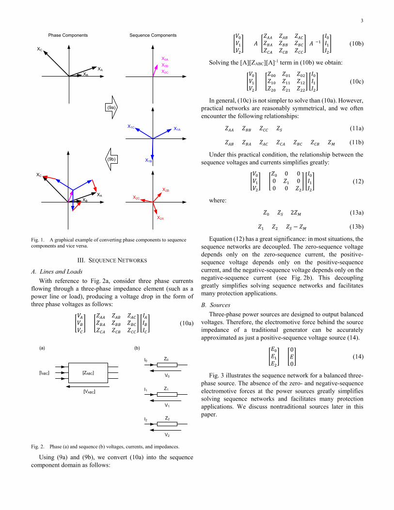
A. Lines and Loads With reference to Fig. 2a, consider three phase currents
flowing through a three-phase impedance element (such as a power line or load), producing a voltage drop in the form of three phase voltages as follows:
�𝑉𝑉𝐴𝐴𝑉𝑉𝐵𝐵𝑉𝑉𝐶𝐶� = �
𝑍𝑍𝐴𝐴𝐴𝐴 𝑍𝑍𝐴𝐴𝐵𝐵 𝑍𝑍𝐴𝐴𝐶𝐶𝑍𝑍𝐵𝐵𝐴𝐴 𝑍𝑍𝐵𝐵𝐵𝐵 𝑍𝑍𝐵𝐵𝐶𝐶𝑍𝑍𝐶𝐶𝐴𝐴 𝑍𝑍𝐶𝐶𝐵𝐵 𝑍𝑍𝐶𝐶𝐶𝐶
� �𝐼𝐼𝐴𝐴𝐼𝐼𝐵𝐵𝐼𝐼𝐶𝐶� (10a)
[ZABC]
[VABC]
[IABC]
(a)
I0 Z0
V0
(b)
Z1
V1
Z2
V2
I1
I2
Fig. 2. Phase (a) and sequence (b) voltages, currents, and impedances.
Using (9a) and (9b), we convert (10a) into the sequence component domain as follows:
�𝑉𝑉0𝑉𝑉1𝑉𝑉2� = [𝐴𝐴] �
𝑍𝑍𝐴𝐴𝐴𝐴 𝑍𝑍𝐴𝐴𝐵𝐵 𝑍𝑍𝐴𝐴𝐶𝐶𝑍𝑍𝐵𝐵𝐴𝐴 𝑍𝑍𝐵𝐵𝐵𝐵 𝑍𝑍𝐵𝐵𝐶𝐶𝑍𝑍𝐶𝐶𝐴𝐴 𝑍𝑍𝐶𝐶𝐵𝐵 𝑍𝑍𝐶𝐶𝐶𝐶
� [𝐴𝐴]−1 �𝐼𝐼0𝐼𝐼1𝐼𝐼2� (10b)
Solving the [A][ZABC][A]-1 term in (10b) we obtain:
�𝑉𝑉0𝑉𝑉1𝑉𝑉2� = �
𝑍𝑍00 𝑍𝑍01 𝑍𝑍02𝑍𝑍10 𝑍𝑍11 𝑍𝑍12𝑍𝑍20 𝑍𝑍21 𝑍𝑍22
� �𝐼𝐼0𝐼𝐼1𝐼𝐼2� (10c)
In general, (10c) is not simpler to solve than (10a). However, practical networks are reasonably symmetrical, and we often encounter the following relationships:
𝑍𝑍𝐴𝐴𝐴𝐴 = 𝑍𝑍𝐵𝐵𝐵𝐵 = 𝑍𝑍𝐶𝐶𝐶𝐶 = 𝑍𝑍𝑆𝑆 (11a)
𝑍𝑍𝐴𝐴𝐵𝐵 = 𝑍𝑍𝐵𝐵𝐴𝐴 = 𝑍𝑍𝐴𝐴𝐶𝐶 = 𝑍𝑍𝐶𝐶𝐴𝐴 = 𝑍𝑍𝐵𝐵𝐶𝐶 = 𝑍𝑍𝐶𝐶𝐵𝐵 = 𝑍𝑍𝑀𝑀 (11b)
Under this practical condition, the relationship between the sequence voltages and currents simplifies greatly:
�𝑉𝑉0𝑉𝑉1𝑉𝑉2� = �
𝑍𝑍0 0 00 𝑍𝑍1 00 0 𝑍𝑍2
� �𝐼𝐼0𝐼𝐼1𝐼𝐼2� (12)
where:
𝑍𝑍0 = 𝑍𝑍𝑆𝑆 + 2𝑍𝑍𝑀𝑀 (13a)
𝑍𝑍1 = 𝑍𝑍2 = 𝑍𝑍𝑆𝑆 − 𝑍𝑍𝑀𝑀 (13b)
Equation (12) has a great significance: in most situations, the sequence networks are decoupled. The zero-sequence voltage depends only on the zero-sequence current, the positive-sequence voltage depends only on the positive-sequence current, and the negative-sequence voltage depends only on the negative-sequence current (see Fig. 2b). This decoupling greatly simplifies solving sequence networks and facilitates many protection applications.
B. Sources Three-phase power sources are designed to output balanced
voltages. Therefore, the electromotive force behind the source impedance of a traditional generator can be accurately approximated as just a positive-sequence voltage source (14).
�𝐸𝐸0𝐸𝐸1𝐸𝐸2� = �
0𝐸𝐸0� (14)
Fig. 3 illustrates the sequence network for a balanced three-phase source. The absence of the zero- and negative-sequence electromotive forces at the power sources greatly simplifies solving sequence networks and facilitates many protection applications. We discuss nontraditional sources later in this paper.
4
[ZABC]
[VABC]
[IABC]
(a)
I0Z0
V0
(b)
I2Z2
V2
I1Z1
V1E
Fig. 3. Sequence networks for a traditional three-phase source.
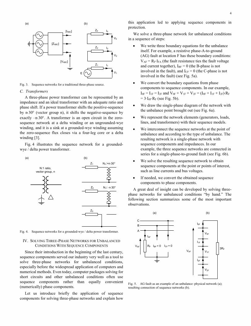
C. Transformers A three-phase power transformer can be represented by an
impedance and an ideal transformer with an adequate ratio and phase shift. If a power transformer shifts the positive-sequence by n⋅30° (vector group n), it shifts the negative-sequence by exactly –n⋅30°. A transformer is an open circuit in the zero-sequence network at a delta winding or an ungrounded-wye winding, and it is a sink at a grounded-wye winding assuming the zero-sequence flux closes via a four-leg core or a delta winding [3].
Fig. 4 illustrates the sequence network for a grounded-wye / delta power transformer.
N:1 ratio, vector group, n
Z1 N∠+n⋅30°
Z2 N∠−n⋅30°
Z0
(a) (b)
Fig. 4. Sequence networks for a grounded-wye / delta power transformer.
IV. SOLVING THREE-PHASE NETWORKS FOR UNBALANCED CONDITIONS WITH SEQUENCE COMPONENTS
Since their introduction in the beginning of the last century, sequence components served our industry very well as a tool to solve three-phase networks for unbalanced conditions, especially before the widespread application of computers and numerical methods. Even today, computer packages solving for short circuits and other unbalanced conditions often use sequence components rather than equally convenient (numerically) phase components.
Let us introduce briefly the application of sequence components for solving three-phase networks and explain how
this application led to applying sequence components in protection.
We solve a three-phase network for unbalanced conditions in a sequence of steps:
• We write three boundary equations for the unbalance itself. For example, a resistive phase-A-to-ground (AG) fault at location F has these boundary conditions: VAF = RF⋅IFA (the fault resistance ties the fault voltage and current together), IBF = 0 (the B-phase is not involved in the fault), and ICF = 0 (the C-phase is not involved in the fault) (see Fig. 5a).
• We convert the boundary equations from phase components to sequence components. In our example, I0F = I1F = I2F and V0F + V1F + V2F = (I0F + I1F + I2F)⋅RF = 3⋅I0F⋅RF (see Fig. 5b).
• We draw the single-phase diagram of the network with the unbalance point brought out (see Fig. 6a).
• We represent the network elements (generators, loads, lines, and transformers) with their sequence models.
• We interconnect the sequence networks at the point of unbalance and according to the type of unbalance. The resulting network is a single-phase network with sequence components and impedances. In our example, the three sequence networks are connected in series for a single-phase-to-ground fault (see Fig. 6b).
• We solve the resulting sequence network to obtain sequence components at the point or points of interest, such as line currents and bus voltages.
• If needed, we convert the obtained sequence components to phase components.
A great deal of insight can be developed by solving three-phase networks for unbalanced conditions “by hand.” The following section summarizes some of the most important observations.
V0F
(b)
I0F
V1F
I1F
V2F
I2F
3RF
IAF
RFVAF IBF = 0 ICF = 0
C
B
A
(a)
VAF
Fig. 5. AG fault as an example of an unbalance: physical network (a); resulting connection of sequence networks (b).

5
Z0SFS
Z2SF
Z1SF
V0F
V2F
V1F
Z0FRR
Z2FR
Z1FR
Z0S
Z2S
Z1S
ES
Z0R
Z2R
Z1R
ER
3RF
I0F
F
S RF
(a)
(b)
VAF
Fig. 6. Simple power system (a) represented with sequence networks for an AG fault (b).
V. SEQUENCE COMPONENTS PROPERTIES Refer to Fig. 6b and note the following: The zero- and negative-sequence networks are passive, i.e.,
they do not contain active sources. The sources present in the positive-sequence network supply the zero- and negative-sequence networks at the unbalance point, where the three networks connect. Therefore, it is convenient to consider zero- and negative-sequence networks as passive networks with the unbalance voltage itself (V0F or V2F in Fig. 6b) driving the sequence voltages and currents.
Without the unbalance, the zero- and negative-sequence networks are deenergized and the corresponding sequence voltages and currents are zero. This makes these zero- and negative-sequence components well suited for disturbance detection in protective relaying (Section VI.H) and related applications such as loss-of-potential (LOP) detection and CT failure detection (Section VI.I).
Being passive, the zero- and negative-sequence networks act as sinks for the currents flowing into these networks from the unbalance point. In these two networks, the current is the highest at the unbalance point and it divides between network elements as it flows toward the network reference potential where it sinks back to the reference. Transformers pass the negative-sequence current, but they sink or stop the zero-sequence current depending on the winding connections (see Fig. 4b). In protective relaying, we often refer to the neutral connections of transformers, autotransformers, or reactors as “ground sources.” More precisely, they are “ground sinks.” The zero-sequence current originates at the unbalance point and it sinks back into ground connections of transformers and grounded sources. It is true that the level of zero-sequence current is higher near more effective grounds than near less effective grounds, but it is only because a more effective ground diverts or sinks the current away from other paths in the zero-sequence network. The power flows from the positive-sequence sources to the unbalance point where the networks are
connected and from the unbalance point into the negative- and zero-sequence networks.
As a result, the zero- and negative-sequence voltages and currents are the highest at the unbalance point, and they become lower in magnitude when measured away from the unbalance point. This improves coordination of sequence overcurrent relays (relays closer to a fault work with higher signals, see Section VI.F) and allows other applications such as multiended fault locating (see Section VI.J).
When the unbalance point is in front of a relay location (in the direction of the CT), the ratio of the zero-sequence voltage to the current at the relay is the negative of the zero-sequence impedance behind the relay. When the unbalance is behind the relay location, the ratio is the impedance in front of the relay. These relationships are not affected by the load current and constitute a solid base for the zero- and negative-sequence directional elements (see Section VI.A and VI.B).
The zero- and negative-sequence networks are not only passive, but they are typically very homogeneous, meaning they contain impedances that have similar angles. This is especially true for the negative-sequence network. Essentially, the negative-sequence network can be viewed as a plain current divider. As a result, the negative-sequence currents across the entire negative-sequence network have similar phase angles. This in turn means that relays could use the angle of the negative-sequence current at the relay location as a good approximation for the angle of any current in the negative-sequence network. This observation facilitates adaptive polarization of reactance distance elements and improved single-ended fault locating (Section VI.D).
The zero- and negative-sequence currents reflect the type of system unbalance. The zero- and negative-sequence networks connect to each other at the unbalance point, and the type of unbalance drives specific relationships between the two sequence currents. These currents preserve their angular position as they flow and sink into the zero- and negative-sequence networks. As a result, the phase angle between the zero- and negative-sequence currents is a very good indicator of the type of unbalance, facilitating fault type identification in protective relays (Section VI.C).
Sinking into the neutral connections of transformers, autotransformers, and reactors, the zero-sequence current flows through the grounded windings. This allows a differential type of protection for these windings, commonly referred to as restricted-earth-fault (REF) protection. Flowing through transformers and stator windings, but not being impacted by load, the negative-sequence current allows sensitive differential protection for transformers and generators. See Section VI.E for details on differential protection with sequence currents.
Finally, let us examine (9a) for deriving the sequence components in the context of constructing a protective device. Sequence components relate to phasors, and phasors represent only signal components of certain frequency. Typically, we are interested in the fundamental frequency components (60 Hz or 50 Hz). Therefore, sequence components require band-pass
6
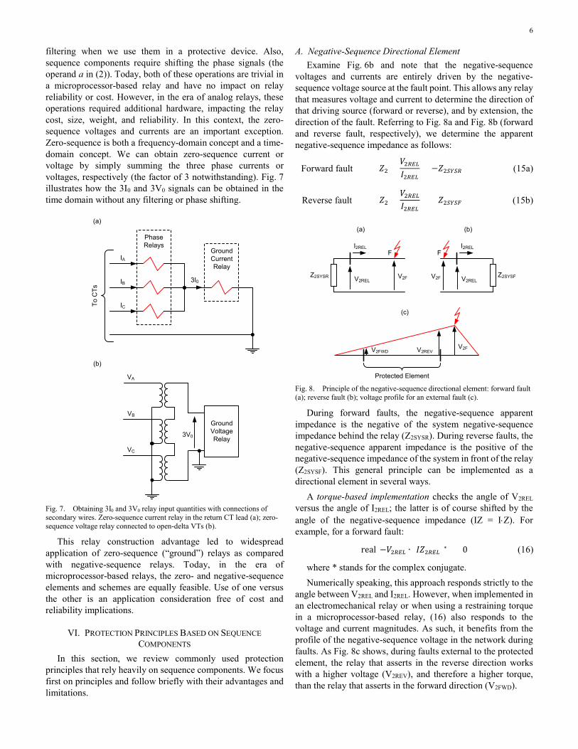
filtering when we use them in a protective device. Also, sequence components require shifting the phase signals (the operand a in (2)). Today, both of these operations are trivial in a microprocessor-based relay and have no impact on relay reliability or cost. However, in the era of analog relays, these operations required additional hardware, impacting the relay cost, size, weight, and reliability. In this context, the zero-sequence voltages and currents are an important exception. Zero-sequence is both a frequency-domain concept and a time-domain concept. We can obtain zero-sequence current or voltage by simply summing the three phase currents or voltages, respectively (the factor of 3 notwithstanding). Fig. 7 illustrates how the 3I0 and 3V0 signals can be obtained in the time domain without any filtering or phase shifting.
Phase Relays
(a)
IA
IB
IC
3I0
GroundCurrent Relay
To C
Ts
GroundVoltage Relay
VA
VB
VC
3V0
(b)
Fig. 7. Obtaining 3I0 and 3V0 relay input quantities with connections of secondary wires. Zero-sequence current relay in the return CT lead (a); zero-sequence voltage relay connected to open-delta VTs (b).
This relay construction advantage led to widespread application of zero-sequence (“ground”) relays as compared with negative-sequence relays. Today, in the era of microprocessor-based relays, the zero- and negative-sequence elements and schemes are equally feasible. Use of one versus the other is an application consideration free of cost and reliability implications.
VI. PROTECTION PRINCIPLES BASED ON SEQUENCE COMPONENTS
In this section, we review commonly used protection principles that rely heavily on sequence components. We focus first on principles and follow briefly with their advantages and limitations.
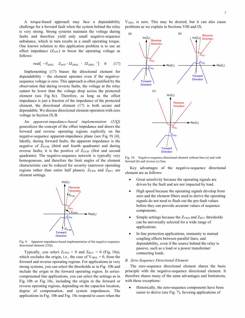
A. Negative-Sequence Directional Element Examine Fig. 6b and note that the negative-sequence
voltages and currents are entirely driven by the negative-sequence voltage source at the fault point. This allows any relay that measures voltage and current to determine the direction of that driving source (forward or reverse), and by extension, the direction of the fault. Referring to Fig. 8a and Fig. 8b (forward and reverse fault, respectively), we determine the apparent negative-sequence impedance as follows:
Forward fault 𝑍𝑍2 =𝑉𝑉2𝑅𝑅𝑅𝑅𝑅𝑅𝐼𝐼2𝑅𝑅𝑅𝑅𝑅𝑅
= −𝑍𝑍2𝑆𝑆𝑆𝑆𝑆𝑆𝑅𝑅 (15a)
Reverse fault 𝑍𝑍2 =𝑉𝑉2𝑅𝑅𝑅𝑅𝑅𝑅𝐼𝐼2𝑅𝑅𝑅𝑅𝑅𝑅
= +𝑍𝑍2𝑆𝑆𝑆𝑆𝑆𝑆𝑆𝑆 (15b)
F
(a)
(c)
(b)
V2FV2REL
I2REL
Z2SYSR
F
V2F V2REL
I2REL
Z2SYSF
V2FV2REVV2FWD
Protected Element Fig. 8. Principle of the negative-sequence directional element: forward fault (a); reverse fault (b); voltage profile for an external fault (c).
During forward faults, the negative-sequence apparent impedance is the negative of the system negative-sequence impedance behind the relay (Z2SYSR). During reverse faults, the negative-sequence apparent impedance is the positive of the negative-sequence impedance of the system in front of the relay (Z2SYSF). This general principle can be implemented as a directional element in several ways.
A torque-based implementation checks the angle of V2REL versus the angle of I2REL; the latter is of course shifted by the angle of the negative-sequence impedance (IZ = I⋅Z). For example, for a forward fault:
real(−𝑉𝑉2𝑅𝑅𝑅𝑅𝑅𝑅 ∙ (𝐼𝐼𝑍𝑍2𝑅𝑅𝑅𝑅𝑅𝑅)∗) > 0 (16)
where * stands for the complex conjugate. Numerically speaking, this approach responds strictly to the
angle between V2REL and I2REL. However, when implemented in an electromechanical relay or when using a restraining torque in a microprocessor-based relay, (16) also responds to the voltage and current magnitudes. As such, it benefits from the profile of the negative-sequence voltage in the network during faults. As Fig. 8c shows, during faults external to the protected element, the relay that asserts in the reverse direction works with a higher voltage (V2REV), and therefore a higher torque, than the relay that asserts in the forward direction (V2FWD).
7
A torque-based approach may face a dependability challenge for a forward fault when the system behind the relay is very strong. Strong systems maintain the voltage during faults and therefore yield only small negative-sequence unbalance, which in turn results in a small operating torque. One known solution to this application problem is to use an offset impedance (ZOFF) to boost the operating voltage as follows:
real�(−𝑉𝑉2𝑅𝑅𝑅𝑅𝑅𝑅 + 𝑍𝑍𝑂𝑂𝑆𝑆𝑆𝑆 ∙ 𝐼𝐼𝑍𝑍2𝑅𝑅𝑅𝑅𝑅𝑅) ∙ (𝐼𝐼𝑍𝑍2𝑅𝑅𝑅𝑅𝑅𝑅)∗� > 0 (17)
Implementing (17) biases the directional element for dependability – the element operates even if the negative-sequence voltage is zero. This approach is often justified by the observation that during reverse faults, the voltage at the relay cannot be lower than the voltage drop across the protected element (see Fig. 8c). Therefore, as long as the offset impedance is just a fraction of the impedance of the protected element, the directional element (17) is both secure and dependable. We discuss directional element operation with zero voltage in Section IX.B.
An apparent-impedance-based implementation (32Q) generalizes the concept of the offset impedance and draws the forward and reverse operating regions explicitly on the negative-sequence apparent-impedance plane (see Fig. 9) [4]. Ideally, during forward faults, the apparent impedance is the negative of ZSYSR (third and fourth quadrants) and during reverse faults, it is the positive of ZSYSF (first and second quadrants). The negative-sequence network is typically very homogeneous, and therefore the limit angles of the element characteristic can be reduced for security (narrower operating regions rather than entire half planes). ZFWD and ZREV are element settings.
Im(Z2)
Re(Z2)ZFWD
ZREV
ZSYSF
‒ZSYSR
Z2ANG
Forward Direction
ReverseDirection
Fig. 9. Apparent-impedance-based implementation of the negative-sequence directional element (32Q).
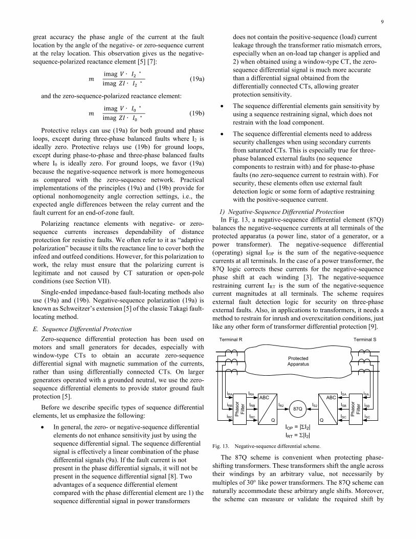
Typically, you select ZFWD < 0 and ZREV > 0 (Fig. 10a), which excludes the origin, i.e., the case of V2REL = 0, from the forward and reverse operating regions. For applications in very strong systems, you can select the thresholds as in Fig. 10b and include the origin in the forward operating region. In series-compensated line applications, you can select the settings as in Fig. 10b or Fig. 10c, including the origin in the forward or reverse operating regions, depending on the capacitor location, degree of compensation, and system impedances. The applications in Fig. 10b and Fig. 10c respond to cases when the
V2REL is zero. This may be desired, but it can also cause problems as we explain in Sections VIII and IX.
Im(Z2)
Re(Z2)ZFWD
ZREV
Forward Direction
ReverseDirection
(a)Im(Z2)
Re(Z2)ZFWD
ZREV
Forward Direction
ReverseDirection
(b)
Im(Z2)
Re(Z2)
ZFWD
ZREV
Forward Direction
ReverseDirection
(c)
Fig. 10. Negative-sequence directional element without bias (a) and with forward (b) and reverse (c) bias.
Key advantages of the negative-sequence directional element are as follows:
• Great sensitivity because the operating signals are driven by the fault and are not impacted by load.
• High speed because the operating signals develop from zero and the element filters used to derive the operating signals do not need to flush out the pre-fault values before they can provide accurate values of sequence components.
• Simple settings because the ZFWD and ZREV thresholds can be universally selected for a wide range of applications.
• In line protection applications, immunity to mutual coupling effects between parallel lines, and dependability, even if the source behind the relay is passive, such as a load or a power transformer connecting loads.
B. Zero-Sequence Directional Element The zero-sequence directional element shares the basic
principle with the negative-sequence directional element. It therefore shares many of the same advantages and limitations, with these exceptions:
• Historically, the zero-sequence components have been easier to derive (see Fig. 7), favoring applications of

8
torque-based zero-sequence elements over negative-sequence elements.
• The zero-sequence network is typically less homogeneous than the negative-sequence network, calling for greater margins in the design, especially for the maximum torque angle and the characteristic limit angle.
• Zero-sequence coupling in parallel lines can cause problems for zero-sequence elements. Often, this weakness is remedied by using negative-sequence directional elements to torque-control zero-sequence overcurrent relays [5].
C. Fault Type Identification Logic As we explained and illustrated in Section IV, the sequence
networks connect at the unbalance point in a manner that reflects the type of unbalance. For example, they are connected in series for single-phase-to-ground faults, resulting in the negative- and zero-sequence fault currents being in phase (see Fig. 5). Because the zero- and negative-sequence networks are homogeneous, the sequence currents at relay locations away from the fault have very similar angles to the sequence currents at the fault location (see Fig. 6b). We can detect the type of ground fault by comparing the angles of the I2 and I0 currents at the relay location. Fig. 11 illustrates this principle.
I2I0
+120°
AG, BCG
CG, ABG
BG, CAG
+60°
‒60°
–120°
Fig. 11. The principle of fault type identification using negative- and zero-sequence currents (ABC phase sequence).
The operating principle of Fig. 11 is very sensitive and fast. However, it is not complete. First, we need an extra logic for balanced three-phase faults. Second, the logic cannot distinguish between single-phase-to-ground faults and double-phase-to-ground faults in the other two phases. In its core, the logic of Fig. 11 only tells us that a specific phase is different than the other two phases. For example, the logic in Fig. 11 shows that the A-phase is different than the B- and C-phases (such is the case for an AG fault but also for a BCG fault).
The following measurements allow us to distinguish single-phase-to-ground faults from double-phase-to-ground faults:
• The angle between the incremental positive-sequence current and the negative-sequence current (see Fig. 12a) [6]. This approach of course must capture and memorize the pre-fault positive-sequence current to derive its incremental value. Therefore, this solution provides a short-lived fault type indication for
instantaneous tripping but not for time-delayed tripping.
• The angle between the positive-sequence voltage and the negative-sequence current (see Fig. 12b). This approach works well if the fault direction is already known. Note that the negative-sequence current position with respect to the positive-sequence voltage is the same for a forward AG fault as it is for a reverse BCG fault.
• The apparent impedance values (m-calculations [5]) for the pair of fault types that yield the same I2 vs I0 angle. If |mA| < |mBC|, then the fault type is AG and not BCG. Just like the positive-sequence voltage approach, this approach must consider forward and reverse faults; it does so by ignoring the signs of the m-values and using their absolute values.
∆I1I2
AG
BG
CG
AB, ABG
BC, BCG
CA, CAG
(a)
V1
IZ2
AG
BG
CG
AB, ABG
BC, BCG
CA, CAG
(b)
Fig. 12. Using the incremental positive-sequence current (a) and the positive-sequence voltage (b) to resolve single-phase and phase-to-phase faults (ABC phase rotation).
D. Distance Element Polarization Consider a distance element measuring the fault loop
voltage V and the fault loop current I for a fault at a per-unit distance m on a line with the impedance Z. The fault resistance is RF and the current at the fault point is IF. We write a fault-point voltage equation as follows:
𝐼𝐼𝑆𝑆𝑅𝑅𝑆𝑆 = 𝑉𝑉 −𝑚𝑚𝑍𝑍𝐼𝐼 (18a)
If we multiply both sides of (18a) by the complex conjugate of IF, the left-hand side of the equation will become a purely real number. Therefore, we can write:
imag(|𝐼𝐼𝑆𝑆|2𝑅𝑅𝑆𝑆) = imag�(𝑉𝑉 −𝑚𝑚𝑍𝑍𝐼𝐼) ∙ (𝐼𝐼𝑆𝑆)∗� = 0 (18b)
We solve (18b) for the fault location m as follows:
𝑚𝑚 =imag(𝑉𝑉 ∙ (𝐼𝐼𝑆𝑆)∗)imag(𝑍𝑍𝐼𝐼 ∙ (𝐼𝐼𝑆𝑆)∗)
(18c)
Equation (18c) is referred to as the “m-calculation” [5] because it gives us the per-unit distance to the fault. Equation (18c) is inherently accurate as long as the fault path is resistive with negligible inductance. We can consider (18c) as an ideal distance element equation or an ideal single-ended fault locator equation. We cannot implement it directly because we do not have access to the current at the fault location (IF). Equation (18c), however, depends on the phase angle of the current at the fault location and is insensitive to the magnitude of that current. Referring to Fig. 6b, we realize that we can approximate with
9
great accuracy the phase angle of the current at the fault location by the angle of the negative- or zero-sequence current at the relay location. This observation gives us the negative-sequence-polarized reactance element [5] [7]:
𝑚𝑚 =imag(𝑉𝑉 ∙ (𝐼𝐼2)∗)imag(𝑍𝑍𝐼𝐼 ∙ (𝐼𝐼2)∗)
(19a)
and the zero-sequence-polarized reactance element:
𝑚𝑚 =imag(𝑉𝑉 ∙ (𝐼𝐼0)∗)imag(𝑍𝑍𝐼𝐼 ∙ (𝐼𝐼0)∗)
(19b)
Protective relays can use (19a) for both ground and phase loops, except during three-phase balanced faults where I2 is ideally zero. Protective relays use (19b) for ground loops, except during phase-to-phase and three-phase balanced faults where I0 is ideally zero. For ground loops, we favor (19a) because the negative-sequence network is more homogeneous as compared with the zero-sequence network. Practical implementations of the principles (19a) and (19b) provide for optional nonhomogeneity angle correction settings, i.e., the expected angle differences between the relay current and the fault current for an end-of-zone fault.
Polarizing reactance elements with negative- or zero-sequence currents increases dependability of distance protection for resistive faults. We often refer to it as “adaptive polarization” because it tilts the reactance line to cover both the infeed and outfeed conditions. However, for this polarization to work, the relay must ensure that the polarizing current is legitimate and not caused by CT saturation or open-pole conditions (see Section VII).
Single-ended impedance-based fault-locating methods also use (19a) and (19b). Negative-sequence polarization (19a) is known as Schweitzer’s extension [5] of the classic Takagi fault-locating method.
E. Sequence Differential Protection Zero-sequence differential protection has been used on
motors and small generators for decades, especially with window-type CTs to obtain an accurate zero-sequence differential signal with magnetic summation of the currents, rather than using differentially connected CTs. On larger generators operated with a grounded neutral, we use the zero-sequence differential elements to provide stator ground fault protection [5].
Before we describe specific types of sequence differential elements, let us emphasize the following:
• In general, the zero- or negative-sequence differential elements do not enhance sensitivity just by using the sequence differential signal. The sequence differential signal is effectively a linear combination of the phase differential signals (9a). If the fault current is not present in the phase differential signals, it will not be present in the sequence differential signal [8]. Two advantages of a sequence differential element compared with the phase differential element are 1) the sequence differential signal in power transformers
does not contain the positive-sequence (load) current leakage through the transformer ratio mismatch errors, especially when an on-load tap changer is applied and 2) when obtained using a window-type CT, the zero-sequence differential signal is much more accurate than a differential signal obtained from the differentially connected CTs, allowing greater protection sensitivity.
• The sequence differential elements gain sensitivity by using a sequence restraining signal, which does not restrain with the load component.
• The sequence differential elements need to address security challenges when using secondary currents from saturated CTs. This is especially true for three-phase balanced external faults (no sequence components to restrain with) and for phase-to-phase faults (no zero-sequence current to restrain with). For security, these elements often use external fault detection logic or some form of adaptive restraining with the positive-sequence current.
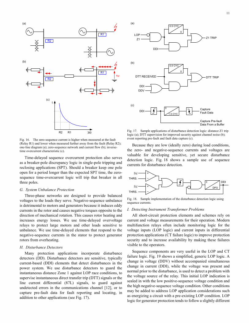
1) Negative-Sequence Differential Protection In Fig. 13, a negative-sequence differential element (87Q)
balances the negative-sequence currents at all terminals of the protected apparatus (a power line, stator of a generator, or a power transformer). The negative-sequence differential (operating) signal IOP is the sum of the negative-sequence currents at all terminals. In the case of a power transformer, the 87Q logic corrects these currents for the negative-sequence phase shift at each winding [3]. The negative-sequence restraining current IRT is the sum of the negative-sequence current magnitudes at all terminals. The scheme requires external fault detection logic for security on three-phase external faults. Also, in applications to transformers, it needs a method to restrain for inrush and overexcitation conditions, just like any other form of transformer differential protection [9].
87Q
ProtectedApparatus
Pha
sor
Filte
r
ABC
Q
iRA
iRB
iRC
IRB
IRA
IRC
IR2
Pha
sor
Filte
r
ABC
Q
iSA
iSC
ISB
ISA
ISC
IS2
Terminal R Terminal S
iSB
IOP = |ΣI2|IRT = Σ|I2|
Fig. 13. Negative-sequence differential scheme.
The 87Q scheme is convenient when protecting phase-shifting transformers. These transformers shift the angle across their windings by an arbitrary value, not necessarily by multiples of 30° like power transformers. The 87Q scheme can naturally accommodate these arbitrary angle shifts. Moreover, the scheme can measure or validate the required shift by

10
looking at the angles between the pre-fault positive-sequence currents at all the transformer windings (the negative-sequence angle shift is the opposite of the positive-sequence angle shift) [10].
2) Restricted-Earth-Fault Protection REF protection for grounded-wye windings of transformers
and autotransformers protects against ground faults near the grounded neutral point of the winding. These faults cause very high currents in the faulted turns but very small currents at the winding terminals. This autotransformer effect between the few faulted turns and the many turns of the entire winding makes it difficult for the transformer differential element to detect these faults.
Strictly speaking, an REF element is a zero-sequence differential element; it compares the zero-sequence current at the winding terminals with the current in the winding neutral connection. By using the zero-sequence at the winding terminals, the scheme is exposed to CT errors during external faults, especially during three-phase and phase-to-phase faults (no true zero-sequence current present). The possibility of a spurious zero-sequence current is especially high in applications with dual-breaker winding terminations where the transformer impedance does not limit the external fault current to about 10 times the transformer rated current. Therefore, we prefer the REF element implemented as a current-polarized directional overcurrent element [3] [5]. The neutral-point current is the operating signal and the zero-sequence current at the winding terminals is the polarizing signal. The neutral-point current must be present for the scheme to operate (see Fig. 14). The neutral-point current cannot be caused by CT saturation, and therefore, its required presence brings security to the scheme. The REF logic is often controlled by the breaker position – if the winding breaker is open, the REF logic is permitted to operate using the neutral-point overcurrent condition alone, without the presence of the polarizing zero-sequence current at the winding terminals.
32
Phas
orFi
lter
ABC
G
iA
iB
iC
IB
IA
IC
3I0
Phas
orFi
lterIN iN
IOP = INIPOL = 3I0
Fig. 14. REF protection using a directional operating principle.
3) Stator-Rotor Differential Protection Another form of negative-sequence differential protection is
a novel scheme that balances the negative-sequence current at the terminals of a synchronous generator (I2) with the double-frequency component field current in the rotor (IF) [11] (see Fig. 15). This scheme detects turn-to-turn faults in both the stator and the rotor. Like the REF scheme, this scheme uses the
presence of the double-frequency component in the field current to validate the negative-sequence component in the stator, thus providing extra security for external three-phase balanced faults.
60
Pha
sor
Filte
r
ABC
Q
iA
iB
iC
IB
IA
IC
I2
Dou
ble-
Freq
uenc
y Fi
lterIF iF
+
SHUNT ‒
Fig. 15. Stator-rotor generator current balance scheme.
F. Time-Coordinated Ground Overcurrent Schemes The sequence currents near the source of the unbalance
(fault) are higher than those further away from the unbalance. This is because the sequence current originating at the unbalance divides between multiple paths as it flows and sinks into grounded transformer windings and grounded power sources (Fig. 16). As a result, inverse-time overcurrent and directional inverse-time overcurrent protective relays are an effective backup for low-current faults, specifically high-resistance faults on transmission lines. These relays respond to zero-sequence current (traditionally) or negative-sequence current and therefore are not impacted by load current. Therefore, they can be set low for sensitivity. Using time delay, they naturally ride through CT saturation errors on heavy, quickly cleared high-current faults. Being time-coordinated, these schemes must follow the same operating principle across the network, or they must apply larger margins to account for differences in the operating principles of nearby relays they coordinate with. Historically, zero-sequence directional overcurrent protection (power systems influenced by ANSI) and zero-sequence wattmetric protection (power systems influenced by IEC) have been applied.
11
(a)
v0F
3I0
t
(b)
(c)
R1
R2
R1
R2
R2 R1
Fig. 16. The zero-sequence current is higher when measured at the fault (Relay R1) and lower when measured further away from the fault (Relay R2); one-line diagram (a); zero-sequence network and current flow (b); inverse-time overcurrent characteristic (c).
Time-delayed sequence overcurrent protection also serves as a breaker-pole discrepancy logic in single-pole tripping and reclosing applications (SPT). Should a breaker keep one pole open for a period longer than the expected SPT time, the zero-sequence time-overcurrent logic will trip that breaker in all three poles.
G. System Unbalance Protection Three-phase networks are designed to provide balanced
voltages to the loads they serve. Negative-sequence unbalance is detrimental to motors and generators because it induces eddy currents in the rotor and causes negative torques opposite to the direction of mechanical rotation. This causes rotor heating and increases energy losses. We use time-delayed overvoltage relays to protect large motors and other loads sensitive to unbalance. We use time-delayed elements that respond to the negative-sequence currents in the stator to protect generator rotors from overheating.
H. Disturbance Detectors Many protection applications incorporate disturbance
detectors (DD). Disturbance detectors are sensitive, typically current-based (DDI) elements that detect disturbances in the power system. We use disturbance detectors to guard the instantaneous distance Zone 1 against LOP race conditions, to supervise instantaneous direct transfer trip (DTT) signals or the line current differential (87L) signals, to guard against undetected errors in the communications channel [12], or to capture pre-fault data for fault reporting and locating, in addition to other applications (see Fig. 17).
LOPZ1
DDI
Z1 TRIP
0.5 CYC
0
(a)
DTT RECEIVED
DDI
DTT TRIP
0.5 CYC
0
(b)
DDV
DDI Capture Fault Data
(c)0
1.5 CYC
Capture Pre-fault Data From a Buffer
Fig. 17. Sample applications of disturbance detection logic: distance Z1 trip logic (a); DTT supervision for improved security against channel noise (b); event reporting pre-fault and fault data capture (c).
Because they are low (ideally zero) during load conditions, the zero- and negative-sequence currents and voltages are valuable for developing sensitive, yet secure disturbance detection logic. Fig. 18 shows a sample use of sequence currents for disturbance detection.
|I0|
THRS.
|I2|
THRS.
0
DPO
DDI–
+
–
+
Fig. 18. Sample implementation of the disturbance detection logic using sequence currents.
I. Detecting Instrument Transformer Problems All short-circuit protection elements and schemes rely on
current and voltage measurements for their operation. Modern multifunction relays often include monitoring logic for the voltage inputs (LOP logic) and current inputs in differential protection applications (CT failure logic) to improve protection security and to increase availability by making these failures visible to the operators.
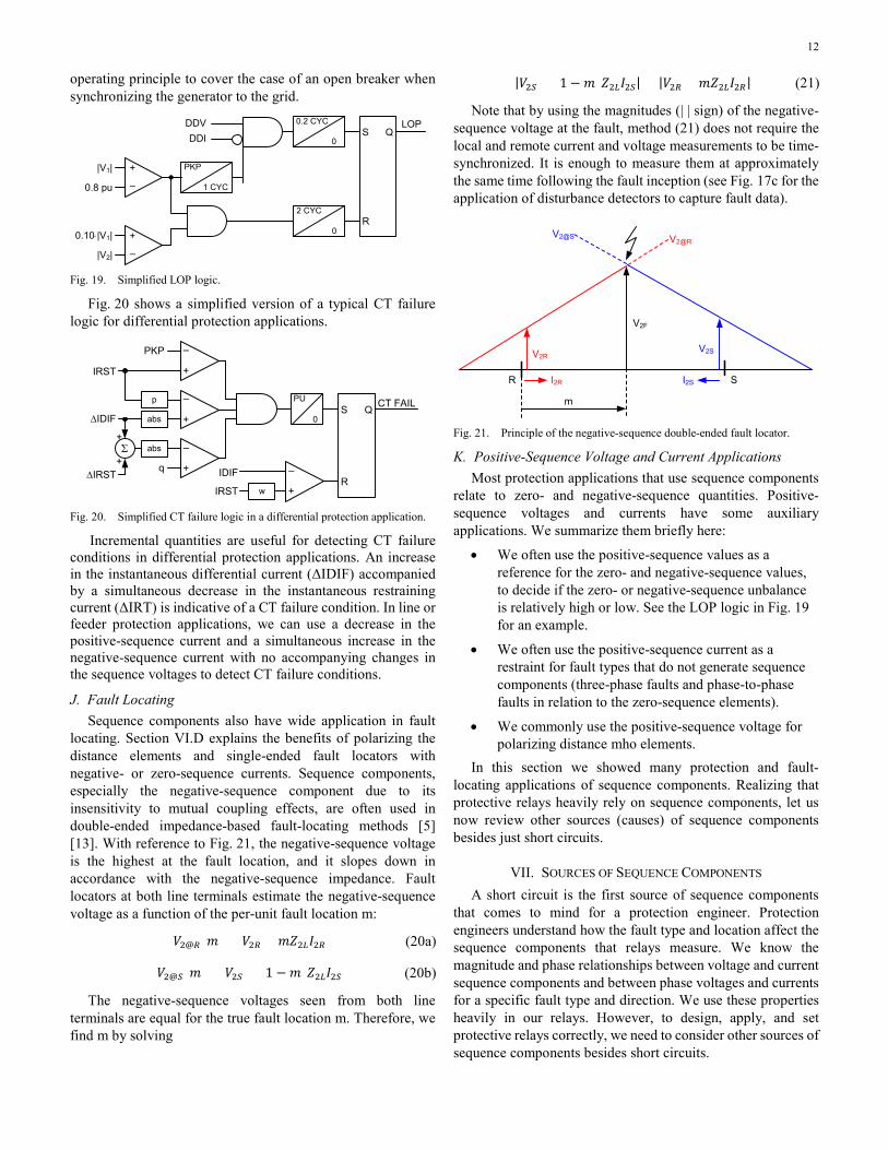
Sequence components are very useful in the LOP and CT failure logic. Fig. 19 shows a simplified, generic LOP logic. A change in voltage (DDV) without accompanied simultaneous change in current (DDI), while the voltage was present and normal prior to the disturbance, is used to detect a problem with the voltage source of the relay. This initial LOP indication is sealed in with the low positive-sequence voltage condition and the high negative-sequence voltage condition. Other conditions may be added to address LOP application considerations such as energizing a circuit with a pre-existing LOP condition. LOP logic for generator protection tends to follow a slightly different
12
operating principle to cover the case of an open breaker when synchronizing the generator to the grid.
|V1|
0.8 pu
PKP
1 CYC
DDVDDI
0.2 CYC
0
2 CYC
0
LOP
0.10⋅|V1|
|V2|
QS
R
–
+
–
+
Fig. 19. Simplified LOP logic.
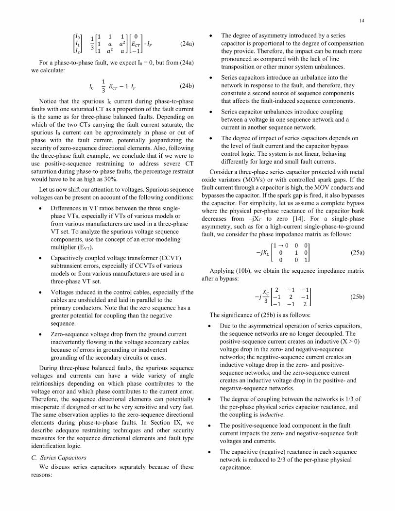
Fig. 20 shows a simplified version of a typical CT failure logic for differential protection applications.
PKP
IRST
PU
0
CT FAILQS
R
+
IDIF
p
w
abs
IRST
–
+
–
+
abs –
+
∆IDIF
–
+
+∆IRST
q
Σ
Fig. 20. Simplified CT failure logic in a differential protection application.
Incremental quantities are useful for detecting CT failure conditions in differential protection applications. An increase in the instantaneous differential current (ΔIDIF) accompanied by a simultaneous decrease in the instantaneous restraining current (ΔIRT) is indicative of a CT failure condition. In line or feeder protection applications, we can use a decrease in the positive-sequence current and a simultaneous increase in the negative-sequence current with no accompanying changes in the sequence voltages to detect CT failure conditions.
J. Fault Locating Sequence components also have wide application in fault
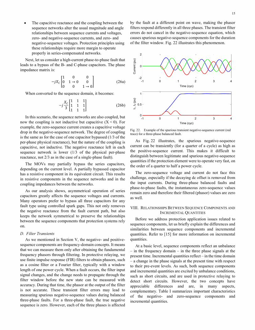
locating. Section VI.D explains the benefits of polarizing the distance elements and single-ended fault locators with negative- or zero-sequence currents. Sequence components, especially the negative-sequence component due to its insensitivity to mutual coupling effects, are often used in double-ended impedance-based fault-locating methods [5] [13]. With reference to Fig. 21, the negative-sequence voltage is the highest at the fault location, and it slopes down in accordance with the negative-sequence impedance. Fault locators at both line terminals estimate the negative-sequence voltage as a function of the per-unit fault location m:
𝑉𝑉2@𝑅𝑅(𝑚𝑚) = 𝑉𝑉2𝑅𝑅 + 𝑚𝑚𝑍𝑍2𝑅𝑅𝐼𝐼2𝑅𝑅 (20a)
𝑉𝑉2@𝑆𝑆(𝑚𝑚) = 𝑉𝑉2𝑆𝑆 + (1 −𝑚𝑚)𝑍𝑍2𝑅𝑅𝐼𝐼2𝑆𝑆 (20b)
The negative-sequence voltages seen from both line terminals are equal for the true fault location m. Therefore, we find m by solving
|𝑉𝑉2𝑆𝑆 + (1 −𝑚𝑚)𝑍𝑍2𝑅𝑅𝐼𝐼2𝑆𝑆| = |𝑉𝑉2𝑅𝑅 + 𝑚𝑚𝑍𝑍2𝑅𝑅𝐼𝐼2𝑅𝑅| (21)
Note that by using the magnitudes (| | sign) of the negative-sequence voltage at the fault, method (21) does not require the local and remote current and voltage measurements to be time-synchronized. It is enough to measure them at approximately the same time following the fault inception (see Fig. 17c for the application of disturbance detectors to capture fault data).
I2R
V2RV2S
I2S
V2F
m
R S
V2@RV2@S
Fig. 21. Principle of the negative-sequence double-ended fault locator.
K. Positive-Sequence Voltage and Current Applications Most protection applications that use sequence components
relate to zero- and negative-sequence quantities. Positive-sequence voltages and currents have some auxiliary applications. We summarize them briefly here:
• We often use the positive-sequence values as a reference for the zero- and negative-sequence values, to decide if the zero- or negative-sequence unbalance is relatively high or low. See the LOP logic in Fig. 19 for an example.
• We often use the positive-sequence current as a restraint for fault types that do not generate sequence components (three-phase faults and phase-to-phase faults in relation to the zero-sequence elements).
• We commonly use the positive-sequence voltage for polarizing distance mho elements.
In this section we showed many protection and fault-locating applications of sequence components. Realizing that protective relays heavily rely on sequence components, let us now review other sources (causes) of sequence components besides just short circuits.
VII. SOURCES OF SEQUENCE COMPONENTS A short circuit is the first source of sequence components
that comes to mind for a protection engineer. Protection engineers understand how the fault type and location affect the sequence components that relays measure. We know the magnitude and phase relationships between voltage and current sequence components and between phase voltages and currents for a specific fault type and direction. We use these properties heavily in our relays. However, to design, apply, and set protective relays correctly, we need to consider other sources of sequence components besides short circuits.

13
A. System Unbalance System unbalance creates low magnitude sequence
components even if there is no short circuit in the system. Also, system unbalance changes the sequence components values if there is a short circuit in the system.
By system unbalance, we mean the following conditions or a combination of them:
• Unbalanced shunt elements, such as single-phase loads, reactors, or capacitor banks, including the case of blown fuses protecting three-phase shunt elements.
• Unbalanced series elements, such as lines that are not transposed at all or not transposed well. A transposed line is symmetrical, meaning its sequence impedances are decoupled (12), only when considered from one terminal to the other. When considered from a given terminal to the location of an internal fault, any line shall be considered as untransposed or partially transposed. Series capacitors are a special case of series unbalance that we cover separately in Section VII.D.
• Open-pole conditions, especially in the vicinity of the protected element and with significant load current at the location of the open pole. Open pole conditions are limited in time. They occur naturally in SPT applications. They may occur inadvertently in any system because of a circuit breaker failure. The pole discrepancy logic trips the partially closed breaker and therefore limits the duration of the open-pole condition to about 1 second. An open-phase condition not related to switching equipment, such as a downed conductor on a power line, is a type of fault to be detected by the protection system.
• Switching operations that create short-lived sequence components when the poles of the current interrupting apparatus transition from all poles closed to all poles open, or vice versa. Because of the natural pole scatter on closing and the zero-crossing current interruption on opening, there is a short period of time – typically up to a few power cycles – during which only one or two poles are closed. During this time, the switching apparatus creates legitimate sequence components at the switching location. Also, a switching apparatus operation may briefly change the sequence components that appeared because of some other unbalance – such as when clearing a fault outside the protection zone. Protection elements need to consider a combination of the unbalances caused by an external fault and a circuit breaker interrupting that fault.
B. Instrument Transformer Errors CT and VT errors affect the sequence component
measurement accuracy, including the case of creating spurious sequence components where the true sequence components are zero. Let us focus on currents first. Assume the A-phase current
is measured with an error, and we use a complex error-modeling multiplier, ECT, to represent that error as follows:
𝐼𝐼𝐴𝐴 = 𝐼𝐼𝐴𝐴(𝑅𝑅𝐴𝐴𝑅𝑅𝑅𝑅𝑂𝑂) ∙ 𝐸𝐸𝐶𝐶𝑅𝑅 (22)
For example, ECT = 0.80∠30° means that the secondary current magnitude is only 80% of the ratio current magnitude and the secondary current leads the ratio current by 30°. Of course, without CT errors, ECT = 1∠0°.
Consider a three-phase balanced fault with CT saturation in Phase A, and calculate the sequence currents as follows:
�𝐼𝐼0𝐼𝐼1𝐼𝐼2� =
13�1 1 11 𝑎𝑎 𝑎𝑎21 𝑎𝑎2 𝑎𝑎
� �𝐸𝐸𝐶𝐶𝑅𝑅𝑎𝑎2𝑎𝑎� ∙ 𝐼𝐼𝑆𝑆 (23a)
For a three-phase balanced fault, we expect I0 = 0 and I2 = 0, but from (23a) we calculate:
𝐼𝐼0 = 𝐼𝐼2 =13
(𝐸𝐸𝐶𝐶𝑅𝑅 − 1)𝐼𝐼𝑆𝑆 (23b)
For example:
For ECT = 0.80∠0°, we obtain I0 = (0.067∠180°)⋅IF, meaning that one third of the error (0.2/3 = 0.067) manifests itself as a spurious I0 current that flows in the opposite direction with respect to the current in the saturated A-phase CT.
For ECT = 0.80∠30°, we obtain I0 = (0.168∠127°)⋅IF, meaning that more than one third of the error manifests itself as a spurious I0 current that has an angle similar to the C-phase current angle.
For a three-phase balanced fault, CT saturation in one phase makes that phase current different than the other two phases, creating an unbalance. This spurious unbalance yields the 0°, +120°, or −120° angle relationship between the spurious I2 and I0 currents, depending on which phase has the saturated CT (see Fig. 11). Without dedicated security logic, CT saturation can result in identifying the wrong fault type during three-phase balanced faults.
In addition, the angle of the spurious I2 or I0 current during a balanced three-phase fault with CT saturation can assume a wide variety of values. These values depend on the degree of saturation (the angle of the ECT error-modeling multiplier) and which phase has the saturated CT. The unpredictable angle of the spurious sequence current in turn can result in misoperation of the negative- and zero-sequence directional elements.
To evaluate the worst-case error, consider deep CT saturation, making the secondary current to be only 20% of the ratio current with the angle advanced by 60°. For ECT = 0.20∠60°, we calculate I0 = (0.305∠169°)⋅IF. In other words, the 80% magnitude error and the 60° phase error lead to a spurious I0 of 30.5% of the fault current (or 3I0 of 91% of the fault current). If we use positive-sequence restraining to address severe CT saturation during three-phase balanced faults, the percentage restraint (I0/I1) would have to be as high as 30%.
Next, consider a phase-to-phase (BC) fault with CT saturation in Phase B, and calculate the sequence currents as follows:
14
�𝐼𝐼0𝐼𝐼1𝐼𝐼2� =
13�1 1 11 𝑎𝑎 𝑎𝑎21 𝑎𝑎2 𝑎𝑎
� �0𝐸𝐸𝐶𝐶𝑅𝑅−1
� ∙ 𝐼𝐼𝑆𝑆 (24a)
For a phase-to-phase fault, we expect I0 = 0, but from (24a) we calculate:
𝐼𝐼0 =13
(𝐸𝐸𝐶𝐶𝑅𝑅 − 1)𝐼𝐼𝑆𝑆 (24b)
Notice that the spurious I0 current during phase-to-phase faults with one saturated CT as a proportion of the fault current is the same as for three-phase balanced faults. Depending on which of the two CTs carrying the fault current saturate, the spurious I0 current can be approximately in phase or out of phase with the fault current, potentially jeopardizing the security of zero-sequence directional elements. Also, following the three-phase fault example, we conclude that if we were to use positive-sequence restraining to address severe CT saturation during phase-to-phase faults, the percentage restraint would have to be as high as 30%.
Let us now shift our attention to voltages. Spurious sequence voltages can be present on account of the following conditions:
• Differences in VT ratios between the three single-phase VTs, especially if VTs of various models or from various manufacturers are used in a three-phase VT set. To analyze the spurious voltage sequence components, use the concept of an error-modeling multiplier (EVT).
• Capacitively coupled voltage transformer (CCVT) subtransient errors, especially if CCVTs of various models or from various manufacturers are used in a three-phase VT set.
• Voltages induced in the control cables, especially if the cables are unshielded and laid in parallel to the primary conductors. Note that the zero sequence has a greater potential for coupling than the negative sequence.
• Zero-sequence voltage drop from the ground current inadvertently flowing in the voltage secondary cables because of errors in grounding or inadvertent grounding of the secondary circuits or cases.
During three-phase balanced faults, the spurious sequence voltages and currents can have a wide variety of angle relationships depending on which phase contributes to the voltage error and which phase contributes to the current error. Therefore, the sequence directional elements can potentially misoperate if designed or set to be very sensitive and very fast. The same observation applies to the zero-sequence directional elements during phase-to-phase faults. In Section IX, we describe adequate restraining techniques and other security measures for the sequence directional elements and fault type identification logic.
C. Series Capacitors We discuss series capacitors separately because of these
reasons:
• The degree of asymmetry introduced by a series capacitor is proportional to the degree of compensation they provide. Therefore, the impact can be much more pronounced as compared with the lack of line transposition or other minor system unbalances.
• Series capacitors introduce an unbalance into the network in response to the fault, and therefore, they constitute a second source of sequence components that affects the fault-induced sequence components.
• Series capacitor unbalances introduce coupling between a voltage in one sequence network and a current in another sequence network.
• The degree of impact of series capacitors depends on the level of fault current and the capacitor bypass control logic. The system is not linear, behaving differently for large and small fault currents.
Consider a three-phase series capacitor protected with metal oxide varistors (MOVs) or with controlled spark gaps. If the fault current through a capacitor is high, the MOV conducts and bypasses the capacitor. If the spark gap is fired, it also bypasses the capacitor. For simplicity, let us assume a complete bypass where the physical per-phase reactance of the capacitor bank decreases from ‒jXC to zero [14]. For a single-phase asymmetry, such as for a high-current single-phase-to-ground fault, we consider the phase impedance matrix as follows:
−𝑗𝑗𝑋𝑋𝐶𝐶 �1 → 0 0 0
0 1 00 0 1
� (25a)
Applying (10b), we obtain the sequence impedance matrix after a bypass:
−𝑗𝑗𝑋𝑋𝐶𝐶3�
2 −1 −1−1 2 −1−1 −1 2
� (25b)
The significance of (25b) is as follows:
• Due to the asymmetrical operation of series capacitors, the sequence networks are no longer decoupled. The positive-sequence current creates an inductive (X > 0) voltage drop in the zero- and negative-sequence networks; the negative-sequence current creates an inductive voltage drop in the zero- and positive-sequence networks; and the zero-sequence current creates an inductive voltage drop in the positive- and negative-sequence networks.
• The degree of coupling between the networks is 1/3 of the per-phase physical series capacitor reactance, and the coupling is inductive.
• The positive-sequence load component in the fault current impacts the zero- and negative-sequence fault voltages and currents.
• The capacitive (negative) reactance in each sequence network is reduced to 2/3 of the per-phase physical capacitance.
15
• The capacitive reactance and the coupling between the sequence networks alter the usual magnitude and angle relationships between sequence currents and voltages, zero- and negative-sequence currents, and zero- and negative-sequence voltages. Protection principles using these relationships require more margin to operate properly in series-compensated networks.
Next, let us consider a high-current phase-to-phase fault that leads to a bypass of the B- and C-phase capacitors. The phase impedance matrix is:
−𝑗𝑗𝑋𝑋𝐶𝐶 �1 0 00 1 → 0 00 0 1 → 0
� (26a)
When converted to the sequence domain, it becomes:
−𝑗𝑗𝑋𝑋𝐶𝐶3�1 1 11 1 11 1 1
� (26b)
In this scenario, the sequence networks are also coupled, but now the coupling is not inductive but capacitive (X < 0). For example, the zero-sequence current creates a capacitive voltage drop in the negative-sequence network. The degree of coupling is the same as for the case of one capacitor bypassed (1/3 of the per-phase physical reactance), but the nature of the coupling is capacitive, not inductive. The negative reactance left in each sequence network is lower (1/3 of the physical per-phase reactance, not 2/3 as in the case of a single-phase fault).
The MOVs may partially bypass the series capacitors, depending on the current level. A partially bypassed capacitor has a resistive component in its equivalent circuit. This results in resistive components in the sequence networks and in the coupling impedances between the networks.
As our analysis shows, asymmetrical operation of series capacitors greatly affects the sequence voltages and currents. Many operators prefer to bypass all three capacitors for any fault type using controlled spark gaps. This not only removes the negative reactance from the fault current path, but also keeps the network symmetrical to preserve the relationships between the sequence components that protection systems rely on.
D. Filter Transients As we mentioned in Section V, the negative- and positive-
sequence components are frequency-domain concepts. It means that we can measure them only after obtaining the fundamental frequency phasors through filtering. In protective relaying, we use finite impulse response (FIR) filters to obtain phasors, such as a cosine filter or a Fourier filter, typically with a window length of one power cycle. When a fault occurs, the filter input signal changes, and the change needs to propagate through the filter window before the new state can be measured with accuracy. During that time, the phasor at the output of the filter is not accurate. These transient filter errors may lead to measuring spurious negative-sequence values during balanced three-phase faults. For a three-phase fault, the true negative sequence is zero. However, each of the three phases is affected
by the fault at a different point on wave, making the phasor filters respond differently in all three phases. The transient filter errors do not cancel in the negative-sequence equation, which causes spurious negative-sequence components for the duration of the filter window. Fig. 22 illustrates this phenomenon.
I 1, I 2
(pu)
Time (cyc)
Time (cyc)
Cur
rent
(pu)
2
0
-2-1 0 1 2 3 4
1
0.5
0-1 0 1 2 3 4
Fig. 22. Example of the spurious transient negative-sequence current (red trace) for a three-phase balanced fault.
As Fig. 22 illustrates, the spurious negative-sequence current can be transiently (for a quarter of a cycle) as high as the positive-sequence current. This makes it difficult to distinguish between legitimate and spurious negative-sequence quantities if the protection element were to operate very fast, on the order of a quarter to half a power cycle.
The zero-sequence voltage and current do not face this challenge, especially if the decaying dc offset is removed from the input currents. During three-phase balanced faults and phase-to-phase faults, the instantaneous zero-sequence values remain zero and therefore their filtered (phasor) values are zero as well.
VIII. RELATIONSHIPS BETWEEN SEQUENCE COMPONENTS AND INCREMENTAL QUANTITIES
Before we address protection application issues related to sequence components, let us briefly explain the differences and similarities between sequence components and incremental quantities. Refer to [15] for more information on incremental quantities.
At a basic level, sequence components reflect an unbalance – in the frequency domain – in the three phase signals at the present time. Incremental quantities reflect – in the time domain – a change in the phase signals at the present time with respect to their pre-event levels. As such, both sequence components and incremental quantities are excited by unbalance conditions, such as short circuits, and are used in protective relaying to detect short circuits. However, the two concepts have appreciable differences and are, in many aspects, complementary. Table I summarizes important characteristics of the negative- and zero-sequence components and incremental quantities.
16
TABLE I SEQUENCE COMPONENTS AND INCREMENTAL QUANTITIES
Characteristics Sequence Components Incremental Quantities
Longevity Available for as long as the unbalance is present.
Require pre-event steady state and are available only for the duration of the incremental quantities memory buffer, typically one to a few power system cycles.
Faults during an open-pole condition
Not very useful. Available and useful if a steady state is reached during the open-pole state before the fault.
Three-phase balanced faults
Not available. Available.
Sensitivity and dependability
Very high, especially in balanced networks with high-accuracy instrument transformers.
Lower because of the finite degree of filtering that can be applied in the short time when the incremental quantities are available.
Security Proper design and application require considering sources of unbalance other than short circuits.
Proper design and application require considering various switching events (other than faults) that create changes in currents and voltages.
Speed Can be fast but need to address spurious sequence components.
Are inherently very fast.
Standing system unbalance
Affected. Not affected.
As Table I shows, the sequence-components-based protection elements and schemes and the incremental-quantity-based protection elements and schemes are complementary to a great degree. Sequence components permit better sensitivity and dependability (notwithstanding three-phase faults, open-pole conditions, and other standing system unbalances). Incremental quantities are faster and can operate during standing network unbalances and three-phase balanced faults. Because of the complementary nature of sequence components and incremental quantities, relays that incorporate both can provide better protection applications [16].
IX. APPLICATION CONSIDERATIONS In this section, we review several design and application
considerations related to protection elements and schemes that heavily rely on sequence components.
A. Securing Sequence Elements for Spurious Sequence Components
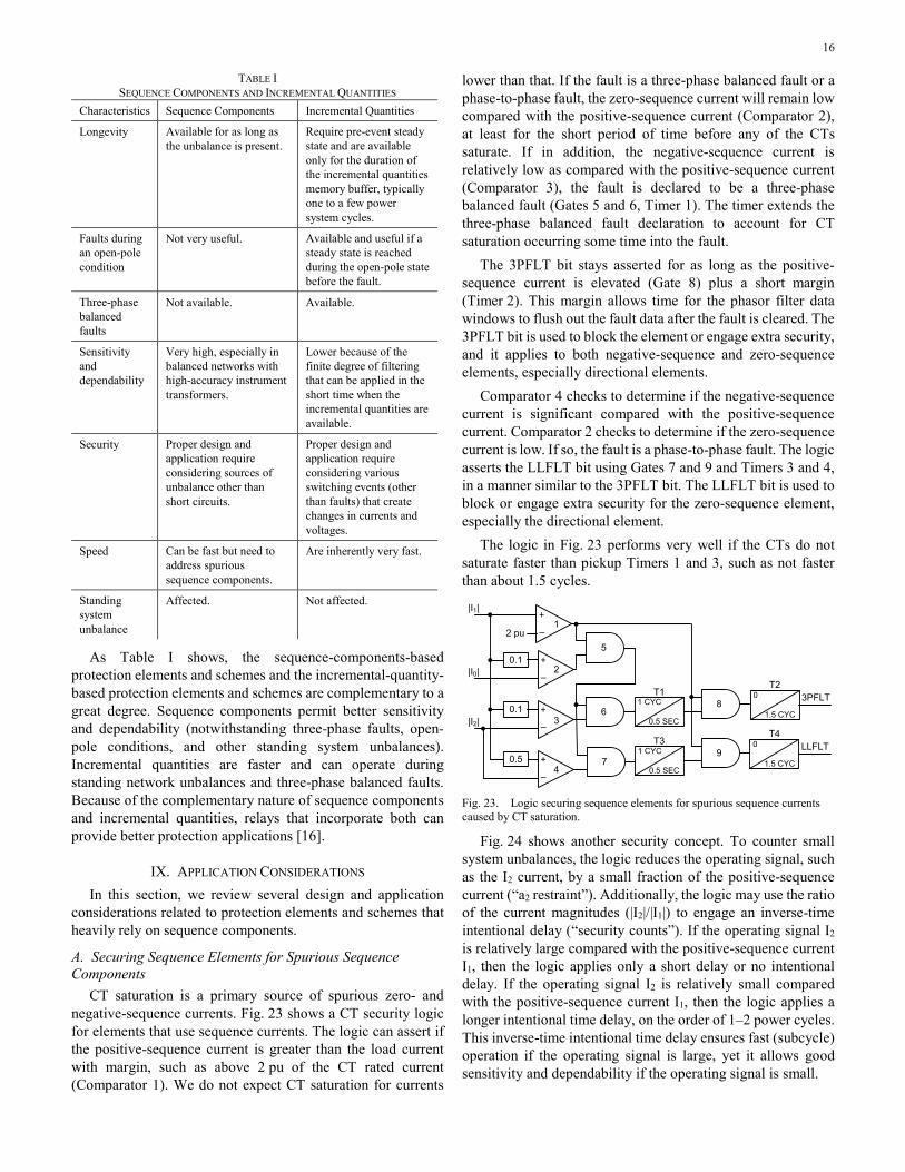
CT saturation is a primary source of spurious zero- and negative-sequence currents. Fig. 23 shows a CT security logic for elements that use sequence currents. The logic can assert if the positive-sequence current is greater than the load current with margin, such as above 2 pu of the CT rated current (Comparator 1). We do not expect CT saturation for currents
lower than that. If the fault is a three-phase balanced fault or a phase-to-phase fault, the zero-sequence current will remain low compared with the positive-sequence current (Comparator 2), at least for the short period of time before any of the CTs saturate. If in addition, the negative-sequence current is relatively low as compared with the positive-sequence current (Comparator 3), the fault is declared to be a three-phase balanced fault (Gates 5 and 6, Timer 1). The timer extends the three-phase balanced fault declaration to account for CT saturation occurring some time into the fault.
The 3PFLT bit stays asserted for as long as the positive-sequence current is elevated (Gate 8) plus a short margin (Timer 2). This margin allows time for the phasor filter data windows to flush out the fault data after the fault is cleared. The 3PFLT bit is used to block the element or engage extra security, and it applies to both negative-sequence and zero-sequence elements, especially directional elements.
Comparator 4 checks to determine if the negative-sequence current is significant compared with the positive-sequence current. Comparator 2 checks to determine if the zero-sequence current is low. If so, the fault is a phase-to-phase fault. The logic asserts the LLFLT bit using Gates 7 and 9 and Timers 3 and 4, in a manner similar to the 3PFLT bit. The LLFLT bit is used to block or engage extra security for the zero-sequence element, especially the directional element.
The logic in Fig. 23 performs very well if the CTs do not saturate faster than pickup Timers 1 and 3, such as not faster than about 1.5 cycles.
|I1|
2 pu1
20.1
|I0|
30.1
|I2|
40.5
5
6
7
1 CYC
0.5 SEC
T1
T3
8
9
0
1.5 CYC
T23PFLT
0
1.5 CYC
T4LLFLT1 CYC
0.5 SEC
–
+
–
+
–
+
–
+
Fig. 23. Logic securing sequence elements for spurious sequence currents caused by CT saturation.
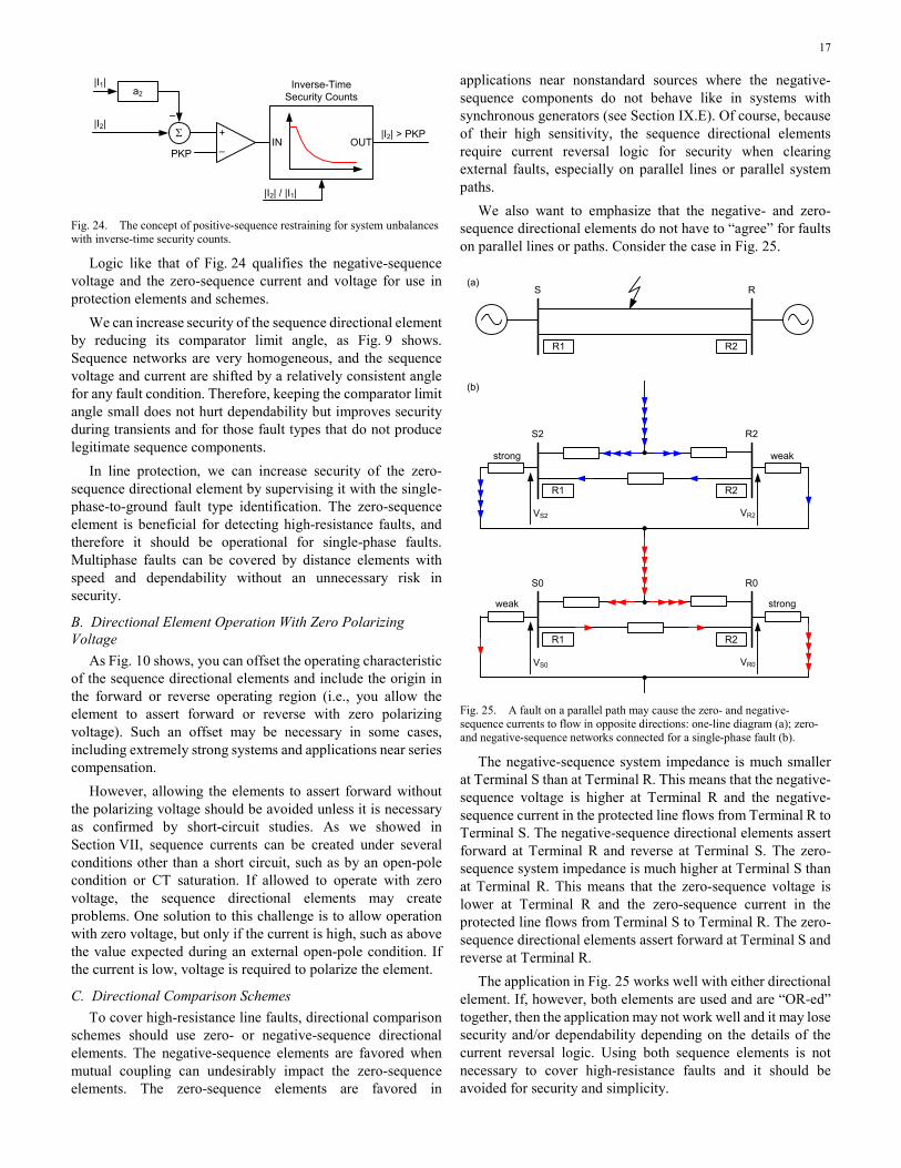
Fig. 24 shows another security concept. To counter small system unbalances, the logic reduces the operating signal, such as the I2 current, by a small fraction of the positive-sequence current (“a2 restraint”). Additionally, the logic may use the ratio of the current magnitudes (|I2|/|I1|) to engage an inverse-time intentional delay (“security counts”). If the operating signal I2 is relatively large compared with the positive-sequence current I1, then the logic applies only a short delay or no intentional delay. If the operating signal I2 is relatively small compared with the positive-sequence current I1, then the logic applies a longer intentional time delay, on the order of 1–2 power cycles. This inverse-time intentional time delay ensures fast (subcycle) operation if the operating signal is large, yet it allows good sensitivity and dependability if the operating signal is small.
17
|I2|
PKP
|I2| > PKP
|I2| / |I1|
Σ‒
a2|I1|
IN OUT
Inverse-Time Security Counts
–
+
Fig. 24. The concept of positive-sequence restraining for system unbalances with inverse-time security counts.
Logic like that of Fig. 24 qualifies the negative-sequence voltage and the zero-sequence current and voltage for use in protection elements and schemes.
We can increase security of the sequence directional element by reducing its comparator limit angle, as Fig. 9 shows. Sequence networks are very homogeneous, and the sequence voltage and current are shifted by a relatively consistent angle for any fault condition. Therefore, keeping the comparator limit angle small does not hurt dependability but improves security during transients and for those fault types that do not produce legitimate sequence components.
In line protection, we can increase security of the zero-sequence directional element by supervising it with the single-phase-to-ground fault type identification. The zero-sequence element is beneficial for detecting high-resistance faults, and therefore it should be operational for single-phase faults. Multiphase faults can be covered by distance elements with speed and dependability without an unnecessary risk in security.
B. Directional Element Operation With Zero Polarizing Voltage
As Fig. 10 shows, you can offset the operating characteristic of the sequence directional elements and include the origin in the forward or reverse operating region (i.e., you allow the element to assert forward or reverse with zero polarizing voltage). Such an offset may be necessary in some cases, including extremely strong systems and applications near series compensation.
However, allowing the elements to assert forward without the polarizing voltage should be avoided unless it is necessary as confirmed by short-circuit studies. As we showed in Section VII, sequence currents can be created under several conditions other than a short circuit, such as by an open-pole condition or CT saturation. If allowed to operate with zero voltage, the sequence directional elements may create problems. One solution to this challenge is to allow operation with zero voltage, but only if the current is high, such as above the value expected during an external open-pole condition. If the current is low, voltage is required to polarize the element.
C. Directional Comparison Schemes To cover high-resistance line faults, directional comparison
schemes should use zero- or negative-sequence directional elements. The negative-sequence elements are favored when mutual coupling can undesirably impact the zero-sequence elements. The zero-sequence elements are favored in
applications near nonstandard sources where the negative-sequence components do not behave like in systems with synchronous generators (see Section IX.E). Of course, because of their high sensitivity, the sequence directional elements require current reversal logic for security when clearing external faults, especially on parallel lines or parallel system paths.
We also want to emphasize that the negative- and zero-sequence directional elements do not have to “agree” for faults on parallel lines or paths. Consider the case in Fig. 25.
(a)
R2
S R
(b)
R2R1
S2 R2
VS2 VR2
strong weak
R2R1
S0 R0
VS0 VR0
strongweak
R1
Fig. 25. A fault on a parallel path may cause the zero- and negative-sequence currents to flow in opposite directions: one-line diagram (a); zero- and negative-sequence networks connected for a single-phase fault (b).
The negative-sequence system impedance is much smaller at Terminal S than at Terminal R. This means that the negative-sequence voltage is higher at Terminal R and the negative-sequence current in the protected line flows from Terminal R to Terminal S. The negative-sequence directional elements assert forward at Terminal R and reverse at Terminal S. The zero-sequence system impedance is much higher at Terminal S than at Terminal R. This means that the zero-sequence voltage is lower at Terminal R and the zero-sequence current in the protected line flows from Terminal S to Terminal R. The zero-sequence directional elements assert forward at Terminal S and reverse at Terminal R.
The application in Fig. 25 works well with either directional element. If, however, both elements are used and are “OR-ed” together, then the application may not work well and it may lose security and/or dependability depending on the details of the current reversal logic. Using both sequence elements is not necessary to cover high-resistance faults and it should be avoided for security and simplicity.
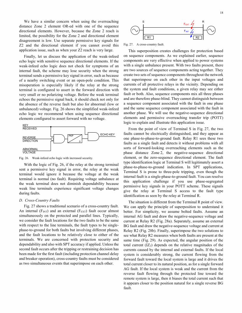
18
We have a similar concern when using the overreaching distance Zone 2 element OR-ed with one of the sequence directional elements. However, because the Zone 2 reach is limited, the possibility for the Zone 2 and directional element disagreement is low. Use separate permissive key signals for Z2 and the directional element if you cannot avoid this application issue, such as when your Z2 reach is very large.
Finally, let us discuss the application of the weak-infeed echo logic with sensitive sequence directional elements. If the weak-infeed echo logic does not check for symptoms of an internal fault, the scheme may lose security when the strong terminal sends a permissive key signal in error, such as because of a nearby switching event or an open-pole condition. This misoperation is especially likely if the relay at the strong terminal is configured to assert in the forward direction with very small or no polarizing voltage. Before the weak terminal echoes the permissive signal back, it should check not only for the absence of the reverse fault but also for abnormal (low or unbalanced) voltage. Fig. 26 shows the simplified weak-infeed echo logic we recommend when using sequence directional elements configured to assert forward with no voltage.
KEYRECEIVED
PKP
0
ABNORMAL VOLTAGE
REVERSE DIRECTION
ECHO KEY
Fig. 26. Weak-infeed echo logic with increased security.
With the logic of Fig. 26, if the relay at the strong terminal sent a permissive key signal in error, the relay at the weak terminal would ignore it because the voltage at the weak terminal is normal (no fault). Requiring voltage unbalance at the weak terminal does not diminish dependability because weak line terminals experience significant voltage changes during faults.
D. Cross-Country Faults Fig. 27 shows a traditional scenario of a cross-country fault.
An internal (FINT) and an external (FEXT) fault occur almost simultaneously on the protected and parallel lines. Typically, we consider the fault locations for the two faults to be the same with respect to the line terminals, the fault types to be single-phase-to-ground for both faults but involving different phases, and the fault locations to be relatively close to either of the terminals. We are concerned with protection security and dependability and also with SPT accuracy if applied. Unless the second fault occurs after the tripping or restraining decision has been made for the first fault (including protection channel delay and breaker operation), cross-country faults must be considered as two simultaneous events that superimpose on each other.
R2R1
S RFEXT
FINT
Fig. 27. A cross-country fault.
This superposition creates challenges for protection based on sequence components. As we explained earlier, sequence components are very effective when applied to power systems with a single unbalance present. With two faults present, there are two sources of sequence components acting together. They create two sets of sequence components throughout the network that superimpose on each other in the input voltages and currents of all protective relays in the vicinity. Depending on the system and fault conditions, a given relay may see either fault or both. Also, sequence components mix all three phases and are therefore phase-blind. They cannot distinguish between a sequence component associated with the fault in one phase and the same sequence component associated with the fault in another phase. We will use the negative-sequence directional elements and permissive overreaching transfer trip (POTT) logic to explain and illustrate this application issue.
From the point of view of Terminal S in Fig. 27, the two faults cannot be electrically distinguished, and they appear as one phase-to-phase-to-ground fault. Relay R1 sees these two faults as a single fault and detects it without problems with all sorts of forward-looking overreaching elements such as the phase distance Zone 2, the negative-sequence directional element, or the zero-sequence directional element. The fault type identification logic at Terminal S will legitimately assert a phase-to-phase-to-ground indication. In SPT applications, Terminal S is prone to three-pole tripping, even though the internal fault is a single-phase-to-ground fault. You can resolve this application challenge if you use phase-segregated permissive key signals in your POTT scheme. These signals give the relay at Terminal S access to the fault type identification as seen by the relay at Terminal R.
The situation is different from the Terminal R point of view. We can apply the principle of superposition to understand it better. For simplicity, we assume bolted faults. Assume an internal AG fault and draw the negative-sequence voltage and current at Relay R2 (Fig. 28a). Separately, assume an external BG fault and draw the negative-sequence voltage and current at Relay R2 (Fig. 28b). Finally, superimpose the two solutions to see what Relay R2 measures when both faults are present at the same time (Fig. 29). As expected, the angular position of the total current (IZ2) depends on the relative magnitudes of the currents caused by the internal and external faults. If the local system is considerably strong, the current flowing from the forward fault toward the local system is large and it drives the total current closer to its natural position, as for a single forward AG fault. If the local system is weak and the current from the reverse fault flowing through the protected line toward the remote system is large, then it biases the total current such that it appears closer to the position natural for a single reverse BG fault.
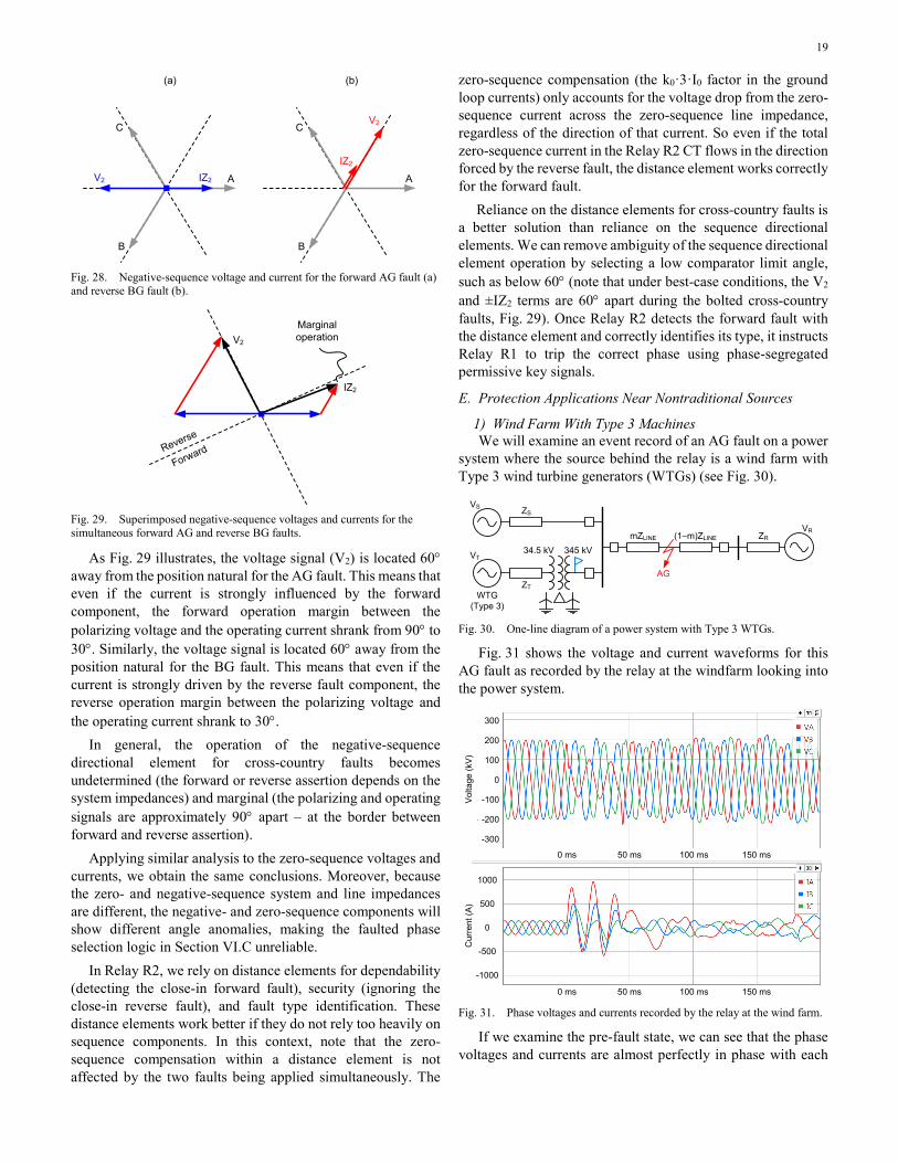
19
V2 A
C
B
(a)
IZ2
V2
A
C
B
(b)
IZ2
Fig. 28. Negative-sequence voltage and current for the forward AG fault (a) and reverse BG fault (b).
V2
IZ2
Reverse
Forward
Marginal operation
Fig. 29. Superimposed negative-sequence voltages and currents for the simultaneous forward AG and reverse BG faults.
As Fig. 29 illustrates, the voltage signal (V2) is located 60° away from the position natural for the AG fault. This means that even if the current is strongly influenced by the forward component, the forward operation margin between the polarizing voltage and the operating current shrank from 90° to 30°. Similarly, the voltage signal is located 60° away from the position natural for the BG fault. This means that even if the current is strongly driven by the reverse fault component, the reverse operation margin between the polarizing voltage and the operating current shrank to 30°.
In general, the operation of the negative-sequence directional element for cross-country faults becomes undetermined (the forward or reverse assertion depends on the system impedances) and marginal (the polarizing and operating signals are approximately 90° apart – at the border between forward and reverse assertion).
Applying similar analysis to the zero-sequence voltages and currents, we obtain the same conclusions. Moreover, because the zero- and negative-sequence system and line impedances are different, the negative- and zero-sequence components will show different angle anomalies, making the faulted phase selection logic in Section VI.C unreliable.
In Relay R2, we rely on distance elements for dependability (detecting the close-in forward fault), security (ignoring the close-in reverse fault), and fault type identification. These distance elements work better if they do not rely too heavily on sequence components. In this context, note that the zero-sequence compensation within a distance element is not affected by the two faults being applied simultaneously. The
zero-sequence compensation (the k0·3·I0 factor in the ground loop currents) only accounts for the voltage drop from the zero-sequence current across the zero-sequence line impedance, regardless of the direction of that current. So even if the total zero-sequence current in the Relay R2 CT flows in the direction forced by the reverse fault, the distance element works correctly for the forward fault.
Reliance on the distance elements for cross-country faults is a better solution than reliance on the sequence directional elements. We can remove ambiguity of the sequence directional element operation by selecting a low comparator limit angle, such as below 60° (note that under best-case conditions, the V2 and ±IZ2 terms are 60° apart during the bolted cross-country faults, Fig. 29). Once Relay R2 detects the forward fault with the distance element and correctly identifies its type, it instructs Relay R1 to trip the correct phase using phase-segregated permissive key signals.
E. Protection Applications Near Nontraditional Sources
1) Wind Farm With Type 3 Machines We will examine an event record of an AG fault on a power
system where the source behind the relay is a wind farm with Type 3 wind turbine generators (WTGs) (see Fig. 30).
VT
WTG(Type 3)
ZT
34.5 kV 345 kV
VS ZS
mZLINE (1–m)ZLINE ZRVR
AG
Fig. 30. One-line diagram of a power system with Type 3 WTGs.
Fig. 31 shows the voltage and current waveforms for this AG fault as recorded by the relay at the windfarm looking into the power system.
Cur
rent
(A)
Vol
tage
(kV
)
300
200
100
0
-100
-200
-300
1000
500
0
-500
-1000
0 ms 50 ms 100 ms 150 ms
0 ms 50 ms 100 ms 150 ms Fig. 31. Phase voltages and currents recorded by the relay at the wind farm.
If we examine the pre-fault state, we can see that the phase voltages and currents are almost perfectly in phase with each
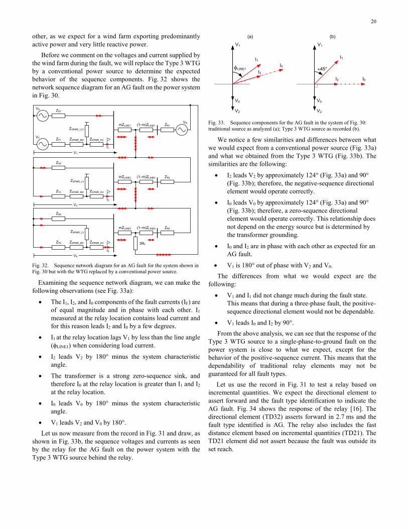
20
other, as we expect for a wind farm exporting predominantly active power and very little reactive power.
Before we comment on the voltages and current supplied by the wind farm during the fault, we will replace the Type 3 WTG by a conventional power source to determine the expected behavior of the sequence components. Fig. 32 shows the network sequence diagram for an AG fault on the power system in Fig. 30.
VT ZT1
VS ZS1
mZLINE1 (1–m)ZLINE1 ZR1VR
ZXFMR_MV ZXFMR_HV
ZXFMR_LV1
V1
ZT2
ZS2
mZLINE2 (1–m)ZLINE2 ZR2
ZXFMR_MV ZXFMR_HV
ZXFMR_LV
V2
I1
I2
ZT0
ZS0
mZLINE0 (1–m)ZLINE0 ZR0
ZXFMR_MV ZXFMR_HV
ZXFMR_LV
V0
I0
3RF
Fig. 32. Sequence network diagram for an AG fault for the system shown in Fig. 30 but with the WTG replaced by a conventional power source.
Examining the sequence network diagram, we can make the following observations (see Fig. 33a):
• The I1, I2, and I0 components of the fault currents (IF) are of equal magnitude and in phase with each other. I1 measured at the relay location contains load current and for this reason leads I2 and I0 by a few degrees.
• I1 at the relay location lags V1 by less than the line angle (ϕLINE1) when considering load current.
• I2 leads V2 by 180° minus the system characteristic angle.
• The transformer is a strong zero-sequence sink, and therefore I0 at the relay location is greater than I1 and I2 at the relay location.
• I0 leads V0 by 180° minus the system characteristic angle.
• V1 leads V2 and V0 by 180°. Let us now measure from the record in Fig. 31 and draw, as
shown in Fig. 33b, the sequence voltages and currents as seen by the relay for the AG fault on the power system with the Type 3 WTG source behind the relay.
(b)
V0
V2
I1
I0I2
≈45°
V1
V0
V2
I1I0
I2φLINE1
(a)
V1
Fig. 33. Sequence components for the AG fault in the system of Fig. 30: traditional source as analyzed (a); Type 3 WTG source as recorded (b).
We notice a few similarities and differences between what we would expect from a conventional power source (Fig. 33a) and what we obtained from the Type 3 WTG (Fig. 33b). The similarities are the following:
• I2 leads V2 by approximately 124° (Fig. 33a) and 90° (Fig. 33b); therefore, the negative-sequence directional element would operate correctly.
• I0 leads V0 by approximately 124° (Fig. 33a) and 90° (Fig. 33b); therefore, a zero-sequence directional element would operate correctly. This relationship does not depend on the energy source but is determined by the transformer grounding.
• I0 and I2 are in phase with each other as expected for an AG fault.
• V1 is 180° out of phase with V2 and V0. The differences from what we would expect are the
following:
• V1 and I1 did not change much during the fault state. This means that during a three-phase fault, the positive-sequence directional element would not be dependable.
• V1 leads I0 and I2 by 90°. From the above analysis, we can see that the response of the
Type 3 WTG source to a single-phase-to-ground fault on the power system is close to what we expect, except for the behavior of the positive-sequence current. This means that the dependability of traditional relay elements may not be guaranteed for all fault types.
Let us use the record in Fig. 31 to test a relay based on incremental quantities. We expect the directional element to assert forward and the fault type identification to indicate the AG fault. Fig. 34 shows the response of the relay [16]. The directional element (TD32) asserts forward in 2.7 ms and the fault type identified is AG. The relay also includes the fast distance element based on incremental quantities (TD21). The TD21 element did not assert because the fault was outside its set reach.
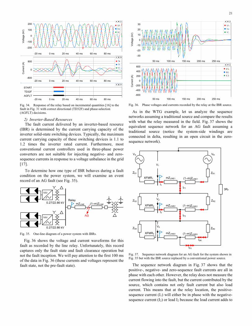
21
Cur
rent
(A)
Vol
tage
(kV
)200
100
0
-100
-200
-20 ms 0 ms 80 ms
800
0
-800
60 ms40 ms20 ms
-20 ms 0 ms 80 ms60 ms40 ms20 ms
-20 ms 0 ms 80 ms60 ms40 ms20 ms
START
TD32F
AGFLT
Fig. 34. Response of the relay based on incremental quantities [16] to the fault in Fig. 31 with correct directional (TD32F) and phase-selection (AGFLT) decisions.
2) Inverter-Based Resources The fault current delivered by an inverter-based resource
(IBR) is determined by the current carrying capacity of the inverter solid-state switching devices. Typically, the maximum current carrying capacity of these switching devices is 1.1 to 1.2 times the inverter rated current. Furthermore, most conventional current controllers used in three-phase power converters are not suitable for injecting negative- and zero-sequence currents in response to a voltage unbalance in the grid [17].
To determine how one type of IBR behaves during a fault condition on the power system, we will examine an event record of an AG fault (see Fig. 35).
mZLINE (1–m)ZLINE
AG
0.27/22.86 kV
0.27/22.86 kVRelay
Fig. 35. One-line diagram of a power system with IBRs.
Fig. 36 shows the voltage and current waveforms for this fault as recorded by the line relay. Unfortunately, this record captures only the fault state and fault clearance operation but not the fault inception. We will pay attention to the first 100 ms of the data in Fig. 36 (these currents and voltages represent the fault state, not the pre-fault state).
30
20
10
0
-10
-20
-30
50 ms 250 ms200 ms150 ms100 ms
50 ms 250 ms200 ms150 ms100 ms
600
400
200
0
-200
-400
-600
Vol
tage
(kV
)C
urre
nt (A
)
Fig. 36. Phase voltages and currents recorded by the relay at the IBR source.
As in the WTG example, let us analyze the sequence networks assuming a traditional source and compare the results with what the relay measured in the field. Fig. 37 shows the equivalent sequence network for an AG fault assuming a traditional source (notice the system-side windings are connected in delta, resulting in an open circuit in the zero-sequence network).
3RF
VS VR
ZS1
ZS2
ZS0
XFMR1 mZLINE1 (1–m)ZLINE1
ZR1
XFMR2
XFMR0
mZLINE2
mZLINE0
ZR2
(1–m)ZLINE2
(1–m)ZLINE0
ZR0
V1
V2
V0
I1
I2
I0R
IF1
IF2
IF0 Fig. 37. Sequence network diagram for an AG fault for the system shown in Fig. 35 but with the IBR source replaced by a conventional power source.
The sequence network diagram in Fig. 37 shows that the positive-, negative- and zero-sequence fault currents are all in phase with each other. However, the relay does not measure the current flowing into the fault, but the current contributed by the source, which contains not only fault current but also load current. This means that at the relay location, the positive-sequence current (I1) will either be in phase with the negative-sequence current (I2) or lead I2 because the load current adds to
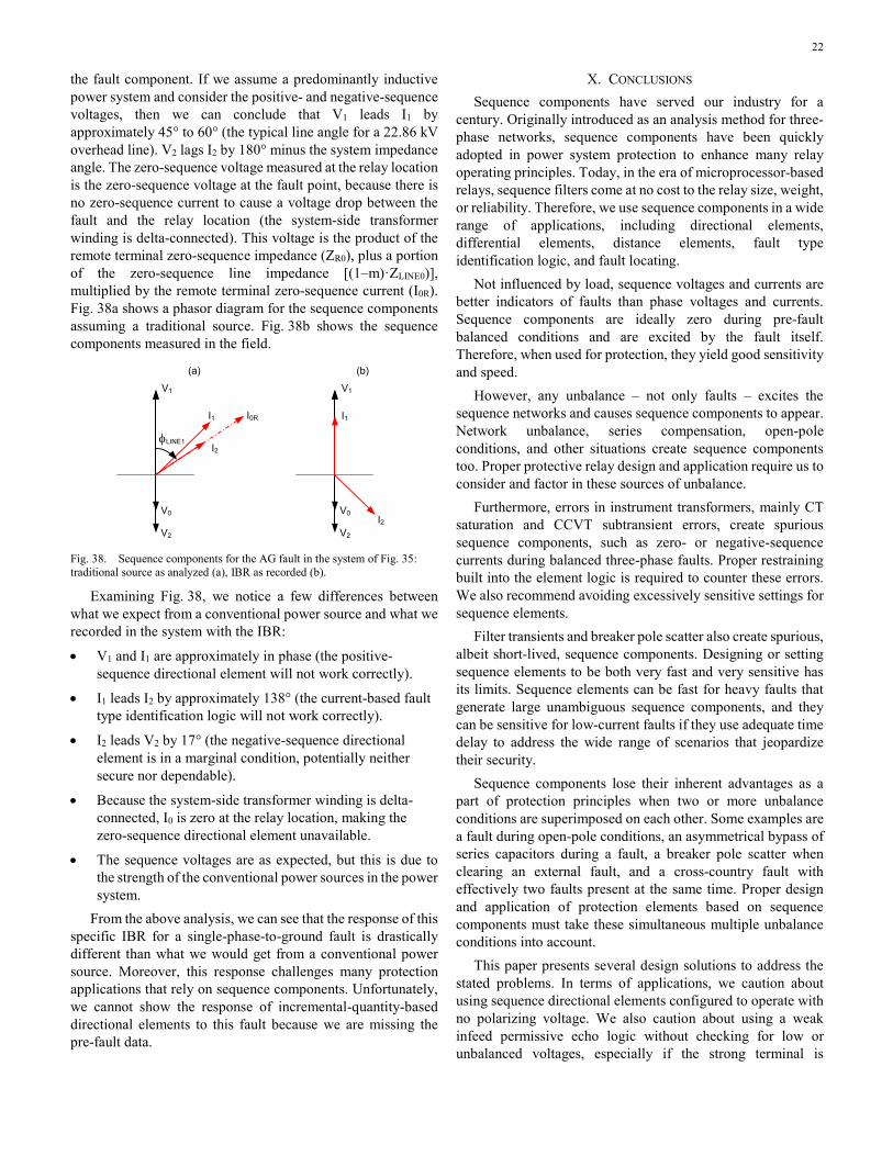
22
the fault component. If we assume a predominantly inductive power system and consider the positive- and negative-sequence voltages, then we can conclude that V1 leads I1 by approximately 45° to 60° (the typical line angle for a 22.86 kV overhead line). V2 lags I2 by 180° minus the system impedance angle. The zero-sequence voltage measured at the relay location is the zero-sequence voltage at the fault point, because there is no zero-sequence current to cause a voltage drop between the fault and the relay location (the system-side transformer winding is delta-connected). This voltage is the product of the remote terminal zero-sequence impedance (ZR0), plus a portion of the zero-sequence line impedance [(1‒m)·ZLINE0)], multiplied by the remote terminal zero-sequence current (I0R). Fig. 38a shows a phasor diagram for the sequence components assuming a traditional source. Fig. 38b shows the sequence components measured in the field.
(b)
V0
V2
I1
I2
V1
V0
V2
I1 I0R
I2φLINE1
(a)
V1
Fig. 38. Sequence components for the AG fault in the system of Fig. 35: traditional source as analyzed (a), IBR as recorded (b).
Examining Fig. 38, we notice a few differences between what we expect from a conventional power source and what we recorded in the system with the IBR:
• V1 and I1 are approximately in phase (the positive-sequence directional element will not work correctly).
• I1 leads I2 by approximately 138° (the current-based fault type identification logic will not work correctly).
• I2 leads V2 by 17° (the negative-sequence directional element is in a marginal condition, potentially neither secure nor dependable).
• Because the system-side transformer winding is delta-connected, I0 is zero at the relay location, making the zero-sequence directional element unavailable.
• The sequence voltages are as expected, but this is due to the strength of the conventional power sources in the power system.
From the above analysis, we can see that the response of this specific IBR for a single-phase-to-ground fault is drastically different than what we would get from a conventional power source. Moreover, this response challenges many protection applications that rely on sequence components. Unfortunately, we cannot show the response of incremental-quantity-based directional elements to this fault because we are missing the pre-fault data.
X. CONCLUSIONS Sequence components have served our industry for a
century. Originally introduced as an analysis method for three-phase networks, sequence components have been quickly adopted in power system protection to enhance many relay operating principles. Today, in the era of microprocessor-based relays, sequence filters come at no cost to the relay size, weight, or reliability. Therefore, we use sequence components in a wide range of applications, including directional elements, differential elements, distance elements, fault type identification logic, and fault locating.
Not influenced by load, sequence voltages and currents are better indicators of faults than phase voltages and currents. Sequence components are ideally zero during pre-fault balanced conditions and are excited by the fault itself. Therefore, when used for protection, they yield good sensitivity and speed.
However, any unbalance – not only faults – excites the sequence networks and causes sequence components to appear. Network unbalance, series compensation, open-pole conditions, and other situations create sequence components too. Proper protective relay design and application require us to consider and factor in these sources of unbalance.
Furthermore, errors in instrument transformers, mainly CT saturation and CCVT subtransient errors, create spurious sequence components, such as zero- or negative-sequence currents during balanced three-phase faults. Proper restraining built into the element logic is required to counter these errors. We also recommend avoiding excessively sensitive settings for sequence elements.
Filter transients and breaker pole scatter also create spurious, albeit short-lived, sequence components. Designing or setting sequence elements to be both very fast and very sensitive has its limits. Sequence elements can be fast for heavy faults that generate large unambiguous sequence components, and they can be sensitive for low-current faults if they use adequate time delay to address the wide range of scenarios that jeopardize their security.
Sequence components lose their inherent advantages as a part of protection principles when two or more unbalance conditions are superimposed on each other. Some examples are a fault during open-pole conditions, an asymmetrical bypass of series capacitors during a fault, a breaker pole scatter when clearing an external fault, and a cross-country fault with effectively two faults present at the same time. Proper design and application of protection elements based on sequence components must take these simultaneous multiple unbalance conditions into account.
This paper presents several design solutions to address the stated problems. In terms of applications, we caution about using sequence directional elements configured to operate with no polarizing voltage. We also caution about using a weak infeed permissive echo logic without checking for low or unbalanced voltages, especially if the strong terminal is
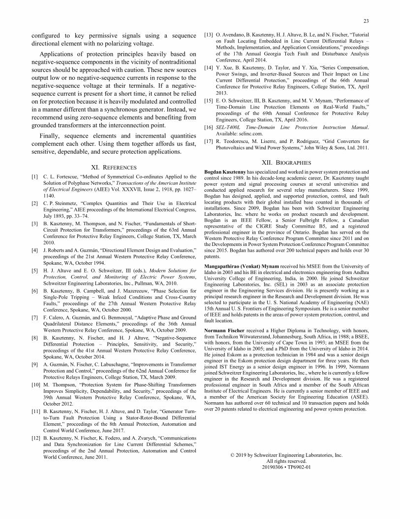
23
configured to key permissive signals using a sequence directional element with no polarizing voltage.
Applications of protection principles heavily based on negative-sequence components in the vicinity of nontraditional sources should be approached with caution. These new sources output low or no negative-sequence currents in response to the negative-sequence voltage at their terminals. If a negative-sequence current is present for a short time, it cannot be relied on for protection because it is heavily modulated and controlled in a manner different than a synchronous generator. Instead, we recommend using zero-sequence elements and benefiting from grounded transformers at the interconnection point.
Finally, sequence elements and incremental quantities complement each other. Using them together affords us fast, sensitive, dependable, and secure protection applications.
XI. REFERENCES [1] C. L. Fortescue, “Method of Symmetrical Co-ordinates Applied to the
Solution of Polyphase Networks,” Transactions of the American Institute of Electrical Engineers (AIEE) Vol. XXXVII, Issue 2, 1918, pp. 1027–1140.
[2] C. P. Steinmetz, “Complex Quantities and Their Use in Electrical Engineering,” AIEE proceedings of the International Electrical Congress, July 1893, pp. 33–74.
[3] B. Kasztenny, M. Thompson, and N. Fischer, “Fundamentals of Short-Circuit Protection for Transformers,” proceedings of the 63rd Annual Conference for Protective Relay Engineers, College Station, TX, March 2010.
[4] J. Roberts and A. Guzmán, “Directional Element Design and Evaluation,” proceedings of the 21st Annual Western Protective Relay Conference, Spokane, WA, October 1994.
[5] H. J. Altuve and E. O. Schweitzer, III (eds.), Modern Solutions for Protection, Control, and Monitoring of Electric Power Systems, Schweitzer Engineering Laboratories, Inc., Pullman, WA, 2010.
[6] B. Kasztenny, B. Campbell, and J. Mazereeuw, “Phase Selection for Single-Pole Tripping – Weak Infeed Conditions and Cross-Country Faults,” proceedings of the 27th Annual Western Protective Relay Conference, Spokane, WA, October 2000.
[7] F. Calero, A. Guzmán, and G. Benmouyal, “Adaptive Phase and Ground Quadrilateral Distance Elements,” proceedings of the 36th Annual Western Protective Relay Conference, Spokane, WA, October 2009.
[8] B. Kasztenny, N. Fischer, and H. J Altuve, “Negative-Sequence Differential Protection – Principles, Sensitivity, and Security,” proceedings of the 41st Annual Western Protective Relay Conference, Spokane, WA, October 2014.
[9] A. Guzmán, N. Fischer, C. Labuschagne, “Improvements in Transformer Protection and Control,” proceedings of the 62nd Annual Conference for Protective Relays Engineers, College Station, TX, March 2009.
[10] M. Thompson, “Protection System for Phase-Shifting Transformers Improves Simplicity, Dependability, and Security,” proceedings of the 39th Annual Western Protective Relay Conference, Spokane, WA, October 2012.
[11] B. Kasztenny, N. Fischer, H. J. Altuve, and D. Taylor, “Generator Turn-to-Turn Fault Protection Using a Stator-Rotor-Bound Differential Element,” proceedings of the 8th Annual Protection, Automation and Control World Conference, June 2017.
[12] B. Kasztenny, N. Fischer, K. Fodero, and A. Zvarych, “Communications and Data Synchronization for Line Current Differential Schemes,” proceedings of the 2nd Annual Protection, Automation and Control World Conference, June 2011.
[13] O. Avendano, B. Kasztenny, H. J. Altuve, B. Le, and N. Fischer, “Tutorial on Fault Locating Embedded in Line Current Differential Relays – Methods, Implementation, and Application Considerations,” proceedings of the 17th Annual Georgia Tech Fault and Disturbance Analysis Conference, April 2014.
[14] Y. Xue, B. Kasztenny, D. Taylor, and Y. Xia, “Series Compensation, Power Swings, and Inverter-Based Sources and Their Impact on Line Current Differential Protection,” proceedings of the 66th Annual Conference for Protective Relay Engineers, College Station, TX, April 2013.
[15] E. O. Schweitzer, III, B. Kasztenny, and M. V. Mynam, “Performance of Time-Domain Line Protection Elements on Real-World Faults,” proceedings of the 69th Annual Conference for Protective Relay Engineers, College Station, TX, April 2016.
[16] SEL-T400L Time-Domain Line Protection Instruction Manual. Available: selinc.com.
[17] R. Teodorescu, M. Liserre, and P. Rodriguez, “Grid Converters for Photovoltaics and Wind Power Systems,” John Wiley & Sons, Ltd. 2011.
XII. BIOGRAPHIES Bogdan Kasztenny has specialized and worked in power system protection and control since 1989. In his decade-long academic career, Dr. Kasztenny taught power system and signal processing courses at several universities and conducted applied research for several relay manufacturers. Since 1999, Bogdan has designed, applied, and supported protection, control, and fault locating products with their global installed base counted in thousands of installations. Since 2009, Bogdan has been with Schweitzer Engineering Laboratories, Inc. where he works on product research and development. Bogdan is an IEEE Fellow, a Senior Fulbright Fellow, a Canadian representative of the CIGRE Study Committee B5, and a registered professional engineer in the province of Ontario. Bogdan has served on the Western Protective Relay Conference Program Committee since 2011 and on the Developments in Power System Protection Conference Program Committee since 2015. Bogdan has authored over 200 technical papers and holds over 30 patents.
Mangapathirao (Venkat) Mynam received his MSEE from the University of Idaho in 2003 and his BE in electrical and electronics engineering from Andhra University College of Engineering, India, in 2000. He joined Schweitzer Engineering Laboratories, Inc. (SEL) in 2003 as an associate protection engineer in the Engineering Services division. He is presently working as a principal research engineer in the Research and Development division. He was selected to participate in the U. S. National Academy of Engineering (NAE) 15th Annual U. S. Frontiers of Engineering Symposium. He is a senior member of IEEE and holds patents in the areas of power system protection, control, and fault location.
Normann Fischer received a Higher Diploma in Technology, with honors, from Technikon Witwatersrand, Johannesburg, South Africa, in 1988; a BSEE, with honors, from the University of Cape Town in 1993; an MSEE from the University of Idaho in 2005; and a PhD from the University of Idaho in 2014. He joined Eskom as a protection technician in 1984 and was a senior design engineer in the Eskom protection design department for three years. He then joined IST Energy as a senior design engineer in 1996. In 1999, Normann joined Schweitzer Engineering Laboratories, Inc., where he is currently a fellow engineer in the Research and Development division. He was a registered professional engineer in South Africa and a member of the South African Institute of Electrical Engineers. He is currently a senior member of IEEE and a member of the American Society for Engineering Education (ASEE). Normann has authored over 60 technical and 10 transaction papers and holds over 20 patents related to electrical engineering and power system protection.
© 2019 by Schweitzer Engineering Laboratories, Inc. All rights reserved.
20190306 • TP6902-01