dimming actuator, 4-gang standard order no. 2015 00
TRANSCRIPT

Product documentationIssue:04.11.202020153100
Dimming actuator, 4-gang StandardOrder no. 2015 00

Table of Contents
Dimming actuator, 4-gang Standard | Order no. 2015 00 | 20153100 Page 2 of 104
Table of Contents1 Information on the product ................................................................................................ 4
1.1 Product catalogue.................................................................................................. 41.2 Function ................................................................................................................. 41.3 Device components ............................................................................................... 61.4 Technical data........................................................................................................ 71.5 Accessories............................................................................................................ 8
2 Safety instructions............................................................................................................. 9
3 Fitting and electrical connection...................................................................................... 10
4 Troubleshooting .............................................................................................................. 12
5 Commissioning................................................................................................................ 15
6 Application programs ...................................................................................................... 17
7 Scope of functions........................................................................................................... 18
8 Notes on software ........................................................................................................... 19
9 Operation and indication ................................................................................................. 209.1 Button operation and indication functions............................................................ 209.2 ETS-Configuration ............................................................................................... 23
9.2.1 Manual operation..................................................................................... 239.2.2 Status indication ...................................................................................... 26
9.3 Operation and indication parameter..................................................................... 289.4 Object list operation and indication...................................................................... 30
10 Dimming operation .......................................................................................................... 3110.1 Channel configuration .......................................................................................... 31
10.1.1 Channel configuration parameter ............................................................ 3210.1.2 Channel configuration object list.............................................................. 33
10.2 Name of the dimming channel ............................................................................. 3410.2.1 Name of the dimming channel parameters.............................................. 35
10.3 Defining load type ................................................................................................ 3610.3.1 Load type parameter ............................................................................... 39
10.4 Operation with universal power booster (OLD).................................................... 4010.4.1 Parameter operation with universal power booster (OLD) ...................... 41
10.5 Dimming characteristic......................................................................................... 4210.5.1 Parameter Dimming characteristic .......................................................... 48
10.6 Brightness range.................................................................................................. 5010.6.1 Brightness range parameter .................................................................... 52

Table of Contents
Dimming actuator, 4-gang Standard | Order no. 2015 00 | 20153100 Page 3 of 104
10.7 Switching / dimming behaviour ............................................................................ 5310.7.1 Switching/dimming behaviour parameters............................................... 56
10.8 Times ................................................................................................................... 5810.8.1 General times parameter ......................................................................... 58
10.9 Reset behaviour................................................................................................... 5910.9.1 Reset behaviour parameter ..................................................................... 61
10.10 Channel-oriented feedback.................................................................................. 6210.10.1Switching status feedback ....................................................................... 6210.10.2Brightness value feedback ...................................................................... 6510.10.3Feedback telegrams parameter............................................................... 6810.10.4Feedback object list ................................................................................. 71
10.11 Time delays.......................................................................................................... 7310.11.1Parameter time delays............................................................................. 74
10.12 Scene function ..................................................................................................... 7510.12.1Parameter scene function........................................................................ 7810.12.2Object list scene function......................................................................... 81
10.13 Staircase function ................................................................................................ 8210.13.1Parameter Staircase function .................................................................. 9010.13.2Object list staircase function.................................................................... 93
10.14 Logic operation function....................................................................................... 9410.14.1Parameter logic operation function.......................................................... 9610.14.2Object list logic operation function........................................................... 97
10.15 disabling function ................................................................................................. 9810.15.1Disabling function/forced position parameter .......................................... 9910.15.2Disabling function/forced position object list .......................................... 102
11 Delivery state ................................................................................................................ 103
Information on the product | Product catalogue
Dimming actuator, 4-gang Standard | Order no. 2015 00 | 20153100 Page 4 of 104
1 Information on the product
1.1 Product catalogue
Product name: Dimming actuator, 4-gang StandardUse: ActuatorDesign: RMDOrder no. 2015 00
1.2 FunctionThe universal dimming actuator works according to the leading edge phase control ortrailing edge phase control dimming principle and makes switching and dimming ofincandescent lamps, HV halogen lamps and LV halogen lamps possible by means ofconventional transformers and Tronic transformers, and dimmable HV LEDs and LVLEDs by means of electronic or conventional transformers or compact fluorescentlamps.
The characteristic of the connected load - provided that the load is supported - canbe automatically measured separately for each output channel and the appropriatedimming procedure can be set. Alternatively, it is possible to predefine the dimmingprocedure using the ETS configuration. This procedure is necessary for loads that donot enable automatic calibration (e.g. with compact fluorescent lamps). 4 dimmingchannels are available. To simplify the configuration, all existing dimming channelscan be assigned to the same parameters in the ETS and thus configured identically.The number of parameters is thereby reduced in the ETS and applied automaticallyon all channels.
The device permits the separate feedback of the individual switching and brightnessstatuses of the connected loads to the KNX.
The pushbuttons on the front panel of the device allow the dimming channels to beswitched on or dimmed by manual operation in parallel with the KNX in a non-pro-grammed state. This feature permits fast checking of connected loads for properfunctioning.
The function features that are independently adjustable for every dimming channel bymeans of the ETS include, for example, separately configurable brightness ranges,extended feedback functions, a logic operation function, separately adjustable dim-ming behaviour, soft dimming functions, time delays and a staircase function withpre-warning before switching off the lighting.
Furthermore, each dimming channel can be integrated in up to 16 scenes with vari-ous brightness values. Central switching of all channels is possible, too. Moreover,the brightness values of the dimming channels in case of bus voltage failure or busvoltage return and after ETS programming, can be preset separately.
The device can be updated. Firmware can be easily updated with the Gira ETS Ser-vice App (additional software).

Information on the product | Function
Dimming actuator, 4-gang Standard | Order no. 2015 00 | 20153100 Page 5 of 104
The device is KNX Data Secure capable. KNX Data Secure offers protection againstmanipulation in building automation and can be configured in the ETS project. De-tailed specialist knowledge is required. A device certificate, which is attached to thedevice, is required for safe commissioning. During mounting, the certificate must beremoved from the device and stored securely.
Planning, installation and commissioning of the device are carried out with the aid ofthe ETS, version 5.7.3 and above or of the ETS6.
The device electronics are supplied exclusively from the bus voltage. The device isdesigned for mounting on DIN-rails in closed compact boxes or in power distributorsin fixed installations in dry rooms.

Information on the product | Device components
Dimming actuator, 4-gang Standard | Order no. 2015 00 | 20153100 Page 6 of 104
1.3 Device components
Image 1: Device components
(1) Button field for manual operation(2) Programming button and LED(3) KNX connection(4) Status LEDs for outputs(5) Load connections

Information on the product | Technical data
Dimming actuator, 4-gang Standard | Order no. 2015 00 | 20153100 Page 7 of 104
1.4 Technical data
Rated voltage AC 110 ... 230 V ~Mains frequency 50 / 60 HzPower loss max. 7 WStandby power approx. 0.16 W per channelAmbient temperature -5 ... +45 °CStorage/transport temperature -25 ... +70 °C
Connected load per channel depends on the connected lamps and the set load type:(see figure 2), (see figure 3)
ETS parameter load typeUNI universal (with automatic calibration procedure)LJ conv. transformer (inductive / leading edge phase control)| LED (leading edge phase control)dž electr. transformer (capacitive / trailing edge phase control){ LED (trailing edge phase control)
Image 2: LED lamp loads

Information on the product | Accessories
Dimming actuator, 4-gang Standard | Order no. 2015 00 | 20153100 Page 8 of 104
Image 3: conventional lamp loads
Inductive capacitive mixed load is not permitted.
Power boosters See power booster instructions
Connection
single stranded 0.5 ... 4 mm²Finely stranded without conductor sleeve 0.5 ... 4 mm²Finely stranded with conductor sleeve 0.5 ... 2.5 mm²Connection torque screw terminals max. 0.8 NmFitting width 72 mm / 4 module
KNX
KNX medium TP256Commissioning mode S-modeRated voltage KNX DC 21 ... 32 V SELVCurrent consumption KNX 6 ... 15 mAConnection mode KNX device connection terminal
1.5 Accessories
Compensation module LED Order no. 2375 00

Safety instructions
Dimming actuator, 4-gang Standard | Order no. 2015 00 | 20153100 Page 9 of 104
2 Safety instructionsElectrical devices may only be mounted and connected by electrically skilledpersons.
Serious injuries, fire or property damage possible. Please read and follow manualfully.
Danger of electric shock. Always disconnect before carrying out work on the deviceor load.
Danger of electric shock. Device is not suitable for disconnection from supplyvoltage. The load is not electrically isolated from the mains even when the output isswitched off.
Risk of destruction of the dimmer and load if the set operating mode and load type donot match. Set the correct dimming principle before connecting or exchanging theload.
Fire hazard. For operation with inductive transformers, each transformer must befused on the primary side in accordance with the manufacturer's instructions. Onlysafety transformers according to EN 61558-2-6 may be used.
The device may not be opened or operated outside the technical specifications.
These instructions are an integral part of the product, and must remain with the endcustomer.

Fitting and electrical connection
Dimming actuator, 4-gang Standard | Order no. 2015 00 | 20153100 Page 10 of 104
3 Fitting and electrical connection
DANGER!Mortal danger of electric shock.Disconnect the device. Cover up live parts.
Fitting the device
In secure operation (preconditions):– Secure commissioning is activated in the ETS.– Device certificate entered/scanned or added to the ETS project. A high resolu-
tion camera should be used to scan the QR code.– Document all passwords and keep them safe.
Observe ambient temperature. Ensure adequate cooling.■ Mount device on DIN rail.■ In secure operation: The device certificate must be removed from the device
and stored securely.
Connecting the device
■ Connect bus line with KNX connecting terminal according to their correct po-larity.
■ Attach the cover cap to the KNX connection as protection against hazardousvoltages.Delivery state: The outputs can be operated with manual control.
In the "Universal" operating mode, the dimming actuator only calibrates itself againafter disconnection of the load and also after commissioning using the ETS.
Inductive capacitive mixed load is not permitted.
Connect 600 Watt LED lamps or compact fluorescent lamps at most per16 ampere circuit breaker. When connecting transformers, observe the data ofthe transformer manufacturer.

Fitting and electrical connection
Dimming actuator, 4-gang Standard | Order no. 2015 00 | 20153100 Page 11 of 104
Image 4: Device connection (connection example)
■ Connect the lamp loads according to the connection example.

Troubleshooting
Dimming actuator, 4-gang Standard | Order no. 2015 00 | 20153100 Page 12 of 104
4 Troubleshooting
Connected LED lamps or compact fluorescent lamps switch off in the lowestdimming position or flicker
The set minimum brightness is too low.Increase minimum brightness.
Connected LED lamps or compact fluorescent lamps flicker
Cause 1: Lamps are not dimmable.Check manufacturer's instructions.Exchange lamps for another type.
Cause 2: Dimming principle and lamps do not optimally match.For HV-LED: Check operation in another dimming principle, reduce connectedload as well if necessary.For LV-LED: Check the lamp operating device and replace as necessary.With the "Universal" setting: Define the dimming principle manually.
Connected HV-LED lamps or compact fluorescent lamps in the lowest dimmingposition are too bright; dimming range is too small
Cause 1: The set minimum brightness is too high.Reduce minimum brightness.
Cause 2: HV-LED trailing edge phase control dimming principle does not optimallymatch the connected lamps.
Check operation in the "HV-LED leading edge phase control" setting, reduceconnected load as well if necessary.Exchange lamps for another type.
Output has switched off.
Cause 1: overheating protection has tripped.Disconnect all outputs from the mains, switch-off the corresponding circuitbreakers.HV-LED trailing edge phase control: Reduce the connected load. Exchangelamps for another type.HV-LED leading edge phase control: Reduce the connected load. Check theoperation in the "HV-LED trailing edge phase control" setting. Exchange lampsfor another type.Let device cool down for at least 15 minutes. Check installation situation, en-sure cooling, e.g. provide distance from surrounding devices.
Cause 2: Surge protection has triggered.

Troubleshooting
Dimming actuator, 4-gang Standard | Order no. 2015 00 | 20153100 Page 13 of 104
HV-LED trailing edge phase control: Check the operation in the "HV-LED lead-ing edge phase control" setting, reduce the connected load as well if neces-sary.Exchange lamps for another type.
The response of the surge protection can be signalled by sending a short-cir-cuit telegram or can be determined by polling the "short-circuit" communicationobject.
Cause 3: short-circuit in output circuitDisconnect all outputs from the mains.Eliminate short-circuit.Switch on the mains voltage of the outputs again. Switch the affected output offand on again.
When a short-circuit occurs the affected output switches off. Automatic restartwhen short-circuit is eliminated within 100 ms (inductive load) or 7 seconds(capacitive or ohmic load). After that lasting switch-off.
When a short-circuit occurs during the calibration process, the load calibratesitself again after the short-circuit is eliminated.
Cause 4: load failure.Check load, replace light bulb. For inductive transformers, check primary fuseand replace if necessary.
Manual control with button field not possible
Cause 1: Manual control has not been programmed.Program manual control.
Cause 2: Manual control via bus disabled.Enable manual control.
None of the outputs can be operated.
Cause 1: All of the outputs are disabled-Cancel disabling.
Cause 2: Manual mode active.Deactivate manual mode (switch off continuous manual mode).
Cause 3: Application software missing or faulty.Check programming and correct.
All outputs off and not possible to switch on
Cause 1: bus voltage failure.Check bus voltage.

Troubleshooting
Dimming actuator, 4-gang Standard | Order no. 2015 00 | 20153100 Page 14 of 104
Luminaires flicker or buzz, proper dimming not possible, device buzzes
Cause: wrong dimming principle setInstallation or commissioning error. Disconnect device and luminaire, switch offcircuit breaker.Check installation and correct.If the wrong dimming principle has been preselected: Set correct dimming prin-ciple.If dimming actuator calibrates itself incorrectly, e.g. with highly inductive mainsor long load cables: preselect correct dimming principle with commissioning.
LED lamp is dimly lit when dimmer is switched off
Cause: LED lamp is not optimally suited for this dimmer.Use a compensation module, see accessories.Use another type of LED lamp or an LED lamp of another manufacturer.

Commissioning
Dimming actuator, 4-gang Standard | Order no. 2015 00 | 20153100 Page 15 of 104
5 Commissioning
Load physical address and application program
■ Press the programming button.The programming LED lights up.
■ Load physical address and application program using the ETS.
Master reset
The master reset restores the basic device setting (physical address 15.15.255, firm-ware remains in place). The device must then be recommissioned with the ETS.Manual operation is possible.
During secure operation: A master reset deactivates device security. The device canthen be recommissioned with the device certificate.
Performing a master reset
Precondition: The safe-state mode is activated.■ Press and hold down the programming button for > 5 s.
The programming LED flashes quickly.
The device performs a master reset, restarts and is ready for operation againafter approx. 5 s.
Safe-state mode
The safe state mode stops the execution of the loaded application program.
Only the system software of the device is still functional. ETS diagnosis func-tions and programming of the device are possible. Manual operation is notpossible.
Activating the safe-state mode
■ Switch off the bus voltage or remove the KNX device connection terminal.■ Wait about 15 s.■ Press and hold down the programming button.■ Switch on the bus voltage or attach the KNX device connection terminal. Re-
lease the programming button only after the programming LED starts flashingslowly.
The safe-state mode is activated.
With a new brief press of the programming button, the programming mode canbe switched on and off as usual also in the safe-state mode. If Programmingmode is active, the programming LED stops flashing.

Commissioning
Dimming actuator, 4-gang Standard | Order no. 2015 00 | 20153100 Page 16 of 104
Deactivating safe-state mode
■ Switch off bus voltage (wait approx. 15 s) or carry out ETS programming.

Application programs
Dimming actuator, 4-gang Standard | Order no. 2015 00 | 20153100 Page 17 of 104
6 Application programs
ETS search paths: Illumination / Dimmer / Dimming actuator, 4-gang
Name Dimming 303AxxVersion: x.x
for ETS5 from Version 5.7.3 onwards and ETS6from mask version SystemB (07B0)Summarized de-scription
Multifunctional dimming application with logic functions andmanual control. KNX Data Secure capable.

Scope of functions
Dimming actuator, 4-gang Standard | Order no. 2015 00 | 20153100 Page 18 of 104
7 Scope of functions
General
– To simplify the configuration, all existing dimming channels can be assigned tothe same parameters in the ETS and thus configured identically.
– Up to 8 independent logic functions for the implementation of simple or com-plex logic operations.
– Actively transmitting feedback or status messages can be delayed globallyafter bus voltage return or after ETS programming.
– Manual operation of outputs independent of the KNX (for instance, construc-tion site mode) with LED status indicators.
Dimming outputs
– Independent switching and dimming of the dimming outputs.– Switching feedback mode: Active (transmitting after changes or cyclically to
the bus) or passive (object readout) feedback function.– Reaction in case of bus voltage failure and bus voltage return as well as after
ETS programming is adjustable for each output.– Logic function individual for each output.– Disabling function can be parameterized for each channel.– Timing functions (switch-on delay, switch-off delay, staircase lighting timer,
also with pre-warning function)– Incorporation into light moods: up to 16 internal scenes parameterizable per
output.– Input monitoring for cyclical updating of the switching object with safety posi-
tion.

Notes on software
Dimming actuator, 4-gang Standard | Order no. 2015 00 | 20153100 Page 19 of 104
8 Notes on software
Unloading the application program
The application program can be unloaded with the ETS. In this case the device iswithout function. Manual operation is no longer possible.
ETS project design and commissioning
For project design and commissioning of the device, ETS5 from Version 5.7.3 on-wards or ETS6 is required. Project designing and commissioning of the device usingETS2, ETS3 or ET4 is not possible.

Operation and indication | Button operation and indication functions
Dimming actuator, 4-gang Standard | Order no. 2015 00 | 20153100 Page 20 of 104
9 Operation and indication
9.1 Button operation and indication functions
Operating elements
Image 5: Operating elements
(4) Status LEDs for outputs– on: output switched on, 1...100%– flashes at 1 Hz: short-circuit or manual mode– flashes at 2 Hz: overload, mains voltage failure or firmware update
(6) Button ǃ– Manual operation
(7) LED ǃ– on: continuous manual mode
(8) LED ON|+– on: selected output on, 1...100%– flashes: Firmware update
(9) Button ON|+– Switch on/increase brightness
(10) Button OFF|−– Switch off/reduce brightness
(11) LED OFF|−– on: Selected output off– flashes: Firmware update
(12) Button ALL OFF– Switching off all outputs
The LEDs (4) optionally indicate the states of the outputs only temporarily(parameter-dependent).
Operating modes
– Bus operation: Operation via push-button sensors or other bus devices

Operation and indication | Button operation and indication functions
Dimming actuator, 4-gang Standard | Order no. 2015 00 | 20153100 Page 21 of 104
– Temporary manual control: manual control locally with keypad, automatic re-turn to bus control
– Continuous manual mode: Exclusively manual operation on the device
No bus operation is possible in manual mode.
After a bus failure and restoration the device switches to bus operation.
Switching on the temporary manual control
Operation using the button field is programmed and not disabled.■ Press button ǃ (6) briefly.
LED ǃ (7) flashes, LED A1... (4) of the first configured output flashes.
Short-time manual operation is switched on.
After 5 s without a key-press, the actuator returns automatically to bus opera-tion.
Switching off temporary manual operation
The device is in short-term manual mode.■ No button-press for 5 s.
- or -
■ Press ǃ (6) button briefly as many time as necessary until the actuatorleaves the short-time manual mode.Status LED A1... (4) no longer flash, but rather indicate the output status.
Short-time manual operation is switched off.
When switching off the manual control, the outputs, depending on the pro-gramming, switch to the active position, e.g. forced position, logic operation.
Switching on permanent manual control
Operation using the button field is programmed and not disabled.
■ Press the ǃ (6) button for at least 5 s.
LED ǃ (7) lights, LED A1... (4) of the first configured output flashes.
Continuous manual mode is switched on.
Switching off permanent manual control
The device is in continuous manual mode.■ Press the ǃ (6) button for at least 5 s.
LED ǃ (7) is off.
Continuous manual mode is switched off. Bus operation is switched on.

Operation and indication | Button operation and indication functions
Dimming actuator, 4-gang Standard | Order no. 2015 00 | 20153100 Page 22 of 104
When switching off the manual control, the outputs, depending on the pro-gramming, switch to the active position, e.g. forced position, logic operation.
Operating the outputs
The device is in continuous or short-term manual mode.
■ Press the button ǃ (6) briefly as many times as necessary until the desiredoutput is selected.The LED of the selected output A1... (4) flashes.
The LEDs ON|+ (8) and OFF|− (11) indicate the status.
■ Operate output with ON|+ (9) button or OFF|− (10) button. Short: switch on/off.Long: dim brighter/darker.Release: Stop dimming.
The LEDs ON|+ (8) and OFF|− (11) indicate the status.
Short-term manual operation: After running through all of the outputs thedevice exits manual mode after another brief press.
Switching off all outputs
The device is in continuous manual mode.
■ Press the ALL OFF button.All outputs are shut off.

Operation and indication | ETS-Configuration
Dimming actuator, 4-gang Standard | Order no. 2015 00 | 20153100 Page 23 of 104
9.2 ETS-Configuration
9.2.1 Manual operationAll outputs of the device have electronic manual operation. The button field with 4function buttons and 3 status LEDs on the front panel of the device can be used forsetting the following modes of operation:
– Bus operation: Operation via push-button sensors or other bus devices– Short-term manual operation: Manual operation locally with button field, auto-
matic return to bus operation.– Permanent manual control: local manual control with keypad
Manual control is possible while the device is supplied with power from the bus sup-ply voltage. In the state as supplied the manual control mode is fully enabled. In thisunprogrammed state, all outputs can be controlled by the manual operation so thatfast function checking of the connected loads (e.g. on the construction site) is pos-sible.
After initial commissioning of the actuator via the ETS, manual control can be en-abled or completely disabled.
Disabling manual control permanently
Manual operation is enabled in the as-delivered state. If the parameter of the samename is deactivated on the "Manual control" parameter page, no parameters andcommunication objects for manual control are available. The outputs can then onlybe controlled via the bus.
In the case of a temporary status indication, the status LEDs continue to indicate thestatus of the outputs when the "Manual control" button is pressed.
Disabling manual control temporarily
The manual control mode can be separately disabled via the bus, even if it is alreadyactive. If the disabling function is enabled, then as soon as a disabling telegram is re-ceived via the disabling object of the manual control, the actuator immediately termin-ates an activated manual control and locks the function keys on the front panel of thedevice. The telegram polarity of the disabling object is parameterisable.
The manual control mode must be enabled■ Activate the parameter "Disabling function" on the "Manual control" parameter
page.The disabling function of the manual control mode is enabled and the disablingobject is visible.
■ Select the desired telegram polarity in the parameter "Polarity of the disablingobject".

Operation and indication | ETS-Configuration
Dimming actuator, 4-gang Standard | Order no. 2015 00 | 20153100 Page 24 of 104
If the polarity is "0 = disabled; 1 = enabled", the disabling function is immedi-ately active on return of bus voltage or after an ETS programming operation(object value "OFF"). To activate the manual control in this case, an enabletelegram "ON" must first be sent to the disabling object.
After return of bus voltage, a disabled state that was active beforehand is al-ways inactive when the polarity of the disabling object is non-inverted.
When an active manual control is terminated by a disable, the actuator willalso transmit a "Manual control inactive" status telegram to the bus, if thestatus messaging function is enabled.
Presetting the behaviour at the beginning and at the end of manual control
The manual control distinguishes the temporary and permanent manual control. Thebehaviour is different depending on these modes of operation, especially at the endof manual control. It should be noted that the operation via the bus, i.e. control of theoutputs by direct operation (switching / dimming / brightness value, scenes, central)or by the disabling or forced position functions is always disabled when the manualcontrol is active. This means that the manual control mode has the highest priority.
Behaviour at the beginning of manual control:The behaviour at the beginning of manual control does not differ for temporary andpermanent manual control. During activation of the manual operation, the brightnessstatuses of the dimming channels remain unchanged. Flashing feature during dis-abling function: The flashing of a disabling function is interrupted at the beginning ofthe manual operation. The brightness adapts itself to the switch-on brightness. Theswitching status is indicated as "ON". Active forced position functions or disablingfunctions can be overridden by manual control. These functions are reactivated afterdeactivation of the manual mode unless they have been cancelled via the bus in themeantime.
Behaviour at the end of manual control:The behaviour at the end of manual control is different for temporary and permanentmanual control. The temporary manual mode is shut off automatically when the lastoutput has been addressed and when the select key c is pressed once more. Dur-ing deactivation of the temporary manual operation mode, the actuator returns to'normal' bus operation and does not change the brightness states selected by manualcontrol. If, however, a forced position or disabling function has been activated viaKNX before or during manual operation, the actuator executes these functions of ahigher priority again for the dimming channels concerned.The permanent manual control mode is shut off, when the select key c is pressedfor more than 5 seconds. Depending on the parameterization of the actuator in theETS, the outputs will be set to the state last adjusted in the manual mode or to thestate internally tracked (direct operation, forced position, disabling) when the perman-ent manual mode is switched off. The parameter "End of permanent manual control"defines the corresponding reaction.
■ Set the parameter "End of permanent manual control" to "no change".
Operation and indication | ETS-Configuration
Dimming actuator, 4-gang Standard | Order no. 2015 00 | 20153100 Page 25 of 104
All telegrams received during an active permanent manual control mode fordirect operation (switching, dimming, brightness value, central, scenes) will berejected. After the end of the permanent manual control mode, the currentbrightness state of all the channels remains unchanged. If, however, a forcedposition or disabling function has been activated via KNX before or duringmanual operation, the actuator executes these functions of a higher priorityagain for the channels concerned.
■ Set the parameter "End of permanent manual control" to "track outputs".During active permanent manual control all incoming telegrams are tracked in-ternally. At the end of manual operation, the channels are set to the lasttracked brightness states. If a forced position or disabling function has beenactivated via the KNX before or during manual control, the actuator executesthese functions of a higher priority again for the channels concerned.
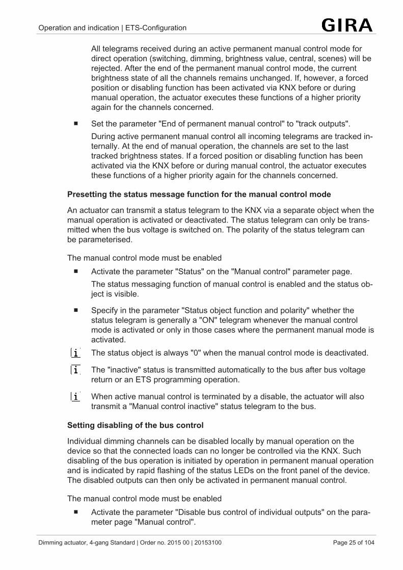
Presetting the status message function for the manual control mode
An actuator can transmit a status telegram to the KNX via a separate object when themanual operation is activated or deactivated. The status telegram can only be trans-mitted when the bus voltage is switched on. The polarity of the status telegram canbe parameterised.
The manual control mode must be enabled■ Activate the parameter "Status" on the "Manual control" parameter page.
The status messaging function of manual control is enabled and the status ob-ject is visible.
■ Specify in the parameter "Status object function and polarity" whether thestatus telegram is generally a "ON" telegram whenever the manual controlmode is activated or only in those cases where the permanent manual mode isactivated.The status object is always "0" when the manual control mode is deactivated.
The "inactive" status is transmitted automatically to the bus after bus voltagereturn or an ETS programming operation.
When active manual control is terminated by a disable, the actuator will alsotransmit a "Manual control inactive" status telegram to the bus.
Setting disabling of the bus control
Individual dimming channels can be disabled locally by manual operation on thedevice so that the connected loads can no longer be controlled via the KNX. Suchdisabling of the bus operation is initiated by operation in permanent manual operationand is indicated by rapid flashing of the status LEDs on the front panel of the device.The disabled outputs can then only be activated in permanent manual control.
The manual control mode must be enabled■ Activate the parameter "Disable bus control of individual outputs" on the para-
meter page "Manual control".

Operation and indication | ETS-Configuration
Dimming actuator, 4-gang Standard | Order no. 2015 00 | 20153100 Page 26 of 104
The function for disabling the bus control is enabled and can be activated loc-ally. Alternatively, deactivating the parameter prevents disabling of the buscontrol from being activated in permanent manual operation.
The disabling initiated locally has the highest priority. Thus all other functionsof the actuator that can be activated via KNX (e.g. forced position or disablingfunction) are overridden. The bus-disabled output remains in the state last setin permanent manual control.Depending on the parameterization of the actuator in the ETS, the groups willbe set to the state last adjusted in the manual mode or to the state internallytracked (direct operation, forced position, disabling) when the permanentmanual mode is reactivated and subsequently shut off.
The disabling function of manual operation does not influence bus-disabledoutputs.
A failure of the bus voltage or an ETS programming operation deactivates dis-abling of the bus control.
9.2.2 Status indicationThe status LEDs on the front of the device can indicate the current status of the dim-ming channels permanently or temporarily.
– Continuous status indication:The parameter "Indicate status temporarily" on the "Status indication" para-meter page is deactivated In the case of a continuous status indication, thestatus LEDs always indicate the current status of the outputs.
– Temporary status indication:The parameter "Indicate status temporarily" on the "Status indication" para-meter page is activated During temporary indication, the status indication isactivated by pressing the "Manual control" button. The display length is set inthe ETS.If manual control is enabled in the ETS, pressing the "Manual control" buttonalso activates short-temporary or permanent manual control. The status indic-ation always remains active during manual operation. At the end of manual op-eration, the display length of the temporary status indication is restarted. Thestatus LEDs then go out after the configured time has elapsed.If manual control is not enabled in the ETS, all status LEDs only show thestatus of the outputs when the "Manual control" button is pressed, dependingon the duration of the display.
In the as-delivered state, the continuous status indication is preset.
If the parameter "Control via object" is activated, the "Temporary status indication"communication object is available in the ETS. This object is bidirectional and canfirstly signal the status of the temporary status indication, and secondly, activate thestatus display. If a temporary status indication has been activated by pressing the

Operation and indication | ETS-Configuration
Dimming actuator, 4-gang Standard | Order no. 2015 00 | 20153100 Page 27 of 104
"Manual control" button, the object sends the value "ON". If the object receives a tele-gram with the value "OFF" or "ON", the status LEDs indicate the status of the outputsaccording to the display length. The manual control is not activated in this case.
By linking the "Temporary status indication" objects of several actuators using a com-mon group address, the indication functions of the status LED can be synchronizedwith one another. It is thus possible to activate the status indications of all actuatorsin a control cabinet at the same time if the manual control only on one actuator - e.g.for service or maintenance purposes - is triggered.In addition, the "Temporary status display" object could be controlled, for example, bya magnetic contact connected to the KNX, so that the status indications of all actuat-ors are activated by opening the control cabinet door. If the door is closed, the statusindications for energy saving remain switched off.
During a running display length, the "Temporary status indication" object doesnot send any new telegrams if the "Manual control" button is pressed again.

Operation and indication | Operation and indication parameter
Dimming actuator, 4-gang Standard | Order no. 2015 00 | 20153100 Page 28 of 104
9.3 Operation and indication parameterManual operation
Manual operation Checkbox (yes / no)Manual control is possible while the device is supplied with power from the bus sup-ply voltage. This parameter defines whether manual operation is to be possible ordeactivated permanently.
End of permanent manual control no changeOutput tracking
The behaviour of the actuator at the end of permanent manual control depends onthis parameter. This parameter is only visible if manual control is enabled.No change: all telegrams received during an active permanent manual control modefor direct operation (switching, dimming, brightness value, scenes) will be rejected.After the end of the permanent manual operation, the current state of all outputswhich was most recently active in manual operation remains unchanged. If, how-ever, a forced position or disabling function has been activated via the KNX beforeor during manual operation, the actuator executes these functions of a higher priorityagain for the dimming channels concerned.Track outputs: during active permanent manual operation, all incoming telegramsand state changes are tracked internally. At the end of manual operation, the chan-nels are set to the last tracked brightness states. If a forced position or disablingfunction has been activated via the KNX before or during manual control, the actu-ator executes these functions of a higher priority again for the channels concerned.This parameter is only visible if manual control is enabled.
Bus control of individual outputs can bedisabled
Checkbox (yes / no)
Individual outputs can be disabled locally during permanent manual control, so thatthe disabled outputs can no longer be controlled via the KNX. Disabling via manualoperation is only permitted if this parameter is activated.This parameter is only visible if manual control is enabled.
Status indication

Operation and indication | Operation and indication parameter
Dimming actuator, 4-gang Standard | Order no. 2015 00 | 20153100 Page 29 of 104
Indicating status temporarily Checkbox (yes / no)The status LEDs on the front of the device can indicate the current status of the dim-ming channels permanently or temporarily.Parameter deactivated: Continuous status indication. In this case, the status LEDsalways indicate the current status of the outputs.Parameter activated: Temporary status indication. In this case, the status indicationis activated by pressing the "Manual control" button. The display length is set in theETS. If manual control is enabled in the ETS, pressing the "Manual control" buttonalso activates short-temporary or permanent manual control. The status indicationalways remains active during manual operation. At the end of manual operation, thedisplay length of the temporary status indication is restarted. The status LEDs thengo out after the configured time has elapsed.
Display length (6...255) 6 ... 10 ... 255This parameter defines the display length if the temporary status indication is activ-ated.
Control via object Checkbox (yes / no)If the parameter "Control via object" is activated, the "Temporary status indication"communication object is available in the ETS. This object is bidirectional and canfirstly signal the status of the temporary status indication, and secondly, activate thestatus display. If a temporary status indication has been activated by pressing the"Manual control" button, the object sends the value "ON". If the object receives atelegram with the value "OFF" or "ON", the status LEDs indicate the status of theoutputs according to the display length. The manual control is not activated in thiscase.

Operation and indication | Object list operation and indication
Dimming actuator, 4-gang Standard | Order no. 2015 00 | 20153100 Page 30 of 104
9.4 Object list operation and indication
Object no. Function Name Type DPT Flag3 Temporary status in-
dicationManual operation -Input/Output
1-bit 1,017 C, (R), W,T, A
1-bit object to signal and activate the temporary status indication. This object is bid-irectional and can firstly signal the status of the temporary status indication, andsecondly, activate the status display. If a temporary status indication has been activ-ated by pressing the "Manual control" button, the object sends the value "ON".If the object receives a telegram with the value "OFF" or "ON", the status LEDs indic-ate the status of the outputs according to the display length. The manual control isnot activated in this case.The object is only visible if the temporary status indication is activated

Dimming operation | Channel configuration
Dimming actuator, 4-gang Standard | Order no. 2015 00 | 20153100 Page 31 of 104
10 Dimming operation
10.1 Channel configuration
Channel configuration
The device is used to dim up to four lighting groups.
Connect 600 Watt LED lamps or compact fluorescent lamps at most per16 ampere circuit breaker. When connecting transformers, observe the data ofthe transformer manufacturer.
Observe delivery state. Before connecting and switching on, program the dim-ming actuator to the changed output configuration.
To simplify the configuration, all existing dimming channels can be assigned to thesame parameters in the ETS and thus configured identically. The parameter "Chan-nel parameters" on the parameter page "General" specifies whether every dimmingchannel of the device can be configured individually or whether all channels shouldbe configured by the same parameters.
In the "all channels equal" setting, the number of parameters in the ETS is reduced.The visible parameters are then used on all channels automatically. Only the commu-nication objects can then be configured separately for the channels. This settingshould be selected, for example, if all channels behave identically and should only beactivated by different group addresses (e.g. in office blocks or in hotel rooms).
The parameter and object configurations of the individual outputs depend onthe parameters on the "General" page and are readjusted by the ETS whenthe channel definition is changed. Consequently, parameter settings or groupaddress assignments to objects can be lost. For this reason, the channeldefinition should be reset when beginning the parameterization of the actuator.

Dimming operation | Channel configuration
Dimming actuator, 4-gang Standard | Order no. 2015 00 | 20153100 Page 32 of 104
10.1.1 Channel configuration parameterGeneral -> Channel configuration
Number of dimming channels 4 dimming channels (O1) + (O2) + (O3) +(O4)
This parameter cannot be changed.
Channel parameters each channel individualall channels equal
To simplify the configuration, all existing dimming channels can be assigned to thesame parameters in the ETS and thus configured identically. This parameter stipu-lates whether every dimming channel of the device can be configured individually orwhether all channels should be configured by the same parameters.In the "all channels equal" setting, the number of parameters in the ETS is reduced.The visible parameters are then used on all channels automatically. Only the com-munication objects can then be configured separately for the channels. This settingshould be selected, for example, if all channels behave identically and should onlybe activated by different group addresses (e.g. in office blocks or in hotel rooms). Inthe "each channel individual" setting, all dimming channels of the device can be con-figured autonomously.

Dimming operation | Channel configuration
Dimming actuator, 4-gang Standard | Order no. 2015 00 | 20153100 Page 33 of 104
10.1.2 Channel configuration object list
Object no. Function Name Type DPT Flag31, 51, 71,91
Switching Dimming channel ...(...) - Input
1-bit 1,001 C, -,W, -, U
1-bit object for switching the dimming channel on or off ("1" = switch on; "0" = switchoff).
Object no. Function Name Type DPT Flag32, 52, 72,92
Switching feedback Dimming channel ...(...) - Output
1-bit 1,001 C, R, -, T, A
1-bit object for feedback signalling of the switching state ("1" = on / "0" = off) to thebus.
Object no. Function Name Type DPT Flag34, 54, 74,94
Dimming Dimming channel ...(...) - Input
4-bit 3,007 C, -,W, -, U
4-bit object for relative dimming of a dimming channel.
Object no. Function Name Type DPT Flag35, 55, 75,95
brightness value Dimming channel ...(...) - Input
1 bytes 5,001 C, -,W, -, U
1-byte object for predefining an absolute dimming value (brightness value 0…255)from the bus.

Dimming operation | Name of the dimming channel
Dimming actuator, 4-gang Standard | Order no. 2015 00 | 20153100 Page 34 of 104
10.2 Name of the dimming channelOptional names can be assigned for each dimming output. The names should clarifythe use of the output (e.g. "living room wall lamp", "bathroom ceiling lamp"). Thenames are only used in the ETS in the text of the parameter pages and communica-tion objects.

Dimming operation | Name of the dimming channel
Dimming actuator, 4-gang Standard | Order no. 2015 00 | 20153100 Page 35 of 104
10.2.1 Name of the dimming channel parametersDimming channel ... -> DO... - General
Name of the dimming channel Free textThe text entered in this parameter is applied to the name of the communication ob-jects and is used to label the dimming output in the ETS parameter window (e.g. "liv-ing room wall lamp", "bathroom ceiling lamp").The text is not programmed in the device.

Dimming operation | Defining load type
Dimming actuator, 4-gang Standard | Order no. 2015 00 | 20153100 Page 36 of 104
10.3 Defining load type
CAUTION!Risk of destruction if the preset dimming principle and connected load do not match.The dimmer and load may be destroyed. Before changing the dimming principle, observe load type. Before changing the load type, make sure that the dimming principle is correct. Before changing the load type, disconnect the load circuit concerned. Check para-meter settings and adjust if necessary.
CAUTION!Danger of destruction from mixed loads.The dimmer and load may be destroyed. Do not connect capacitive loads, e.g. electronic transformers, and inductive loads,e.g. inductive transformers, together on the same dimmer output. Do not connect inductive transformers together with HV LED lamps or compact fluor-escent lamps on the same dimmer output.
The device works according to the leading edge phase control or trailing edge phasecontrol dimming principle and makes switching and dimming of incandescent lamps,HV halogen lamps and LV halogen lamps, compact fluorescent lamps as well as HVLEDs and LV LEDs possible by means of conventional transformers and Tronictransformers. The characteristic of the connected load can automatically be meas-ured separately for each dimming channel and the appropriate dimming procedurecan be set. Alternatively, the dimming procedure can be predefined by a parameter inthe ETS without calibration taking place. This procedure is necessary for loads thatdo not enable automatic calibration.
When selecting the appropriate dimming principle, the specifications of thelamp manufacturer and/or transformer manufacturer should generally be ob-served.
■ Set the parameter to "universal (with calibration procedure)".The dimming channel calibrates itself universally to the connected load type.After programming in the ETS, after bus voltage return, or after switching onthe mains voltage supply of a load output, the actuator calibrates itself auto-matically to the connected load. The calibration procedure becomes noticeableduring ohmic loads by a brief flicker and lasts up to 10 seconds depending onthe network conditions.
This setting must not be selected for loads that do not enable automatic calib-ration. In this case, a suitable dimming principle must be preselected (see fol-lowing settings).
■ Set the parameter to "electronic transformer (capacitive / phase cut-off)".

Dimming operation | Defining load type
Dimming actuator, 4-gang Standard | Order no. 2015 00 | 20153100 Page 37 of 104
The dimming channel is preset to trailing edge phase control principle. Thereis no automatic calibration of the load type. Ohmic loads, electronic trans-formers or LV-LEDs (via Tronic transformers) can be connected to the output.
■ Set the parameter to "conventional transformer (inductive/leading edge phasecontrol)".The dimming channel is preset to leading edge phase control principle. Thereis no automatic calibration of the load type. Conventional transformers or LV-LEDs (via conv. transformers) can be connected to the output.
■ Set the parameter to "LED (Phase cut-off)". The dimming channel is preset toan optimized trailing edge phase control principle.There is no automatic calibration of the load type. HV LED or compact fluores-cent lamps optimized for this dimming principle can be connected to the out-put.
■ Set the parameter to "LED (Phase cut-on)".The dimming channel is preset to an optimized leading edge phase controlprinciple. There is no automatic calibration of the load type. HV LED or com-pact fluorescent lamps optimized for this dimming principle can be connectedto the output. Conventional transformers cannot be connected to the output.
In the as-delivered state of the device, the dimming principle is set to "univer-sal" for all outputs.
When changing a load type on an output, the dimming principle must also bechanged if necessary!
Recommendation for the configuration of the dimming principle with HV-LED lamps:
It is recommended to set the "Type of connected load" in the ETS to "universal" (thisdimming principle also corresponds to the as-delivered state of the dimming actu-ator). If automatic calibration of the load does not work or produces insufficient dim-ming results, it is recommended to operate HV LED lamps preferably in the load type"LED trailing edge phase control", regardless of the manufacturer's specification. Theadvantage of this setting lies in the fact that a dimming output can provide the max-imum LED nominal load (see technical data). This is often not possible in leadingedge phase control principle. Only configure the type of load in the ETS to "LED lead-ing edge phase control" if the operation of the connected LED lamps in the trailingedge phase control principle is not satisfactory (e.g. dimming range is too small).
Protection functions (over-voltage switch-off) ensure that the device is not destroyedif the connected LED lamps are controlled in a dimming principle that the manufac-turer has not designed them for.
Problem resolution with HV-LED lamps: Possible problems during operation of HV LED lamps and their remedial measuresare demonstrated in the following.
Parameter setting "LED trailing edge phase control" -> Problems:

Dimming operation | Defining load type
Dimming actuator, 4-gang Standard | Order no. 2015 00 | 20153100 Page 38 of 104
– Dimming range too small– Minimum brightness too high– Lamps flicker– Output switches off due to overvoltage
Remedy: Check operation in the leading edge phase control, reduce connected loadas well if necessary, exchange lamps for another type.
Parameter setting "LED leading edge phase control" -> Problems:
– Lamps flicker– Dimmer actuator overheats (output switches off due to overtemperature)– Dimmer actuator hums
Remedy: Reduce connected load, check operation in the trailing edge phase control,exchange lamps for another type.

Dimming operation | Defining load type
Dimming actuator, 4-gang Standard | Order no. 2015 00 | 20153100 Page 39 of 104
10.3.1 Load type parameterDimming channel ... -> DO... - General
Load type universal (with automatic calibration pro-cedure)electr. transformer (capacitive / trailingedge phase control)conv. transformer (inductive / leadingedge phase control)LED (trailing edge phase control)LED (leading edge phase control)
The dimming principle of the dimming channel is specified here.universal (with automatic calibration procedure): The dimming channel calibrates it-self universally to the connected load type. After programming with the ETS, afterbus voltage return (without mains voltage) or after switching on the mains voltagesupply of a load output, the actuator calibrates itself automatically to the connectedload. The calibration procedure becomes noticeable during ohmic loads by a briefflicker and lasts up to 10 seconds depending on the network conditions.Electronic transformer (capacitive/trailing edge phase control): The dimming channelis preset to the trailing edge phase control principle. There is no automatic calibra-tion of the load type. Ohmic loads or electronic transformers can be connected to theoutput.Conventional transformer (inductive/leading edge phase control): The dimmingchannel is preset to the leading edge phase control principle. There is no automaticcalibration of the load type. Conventional transformers can be connected to the out-put.LED (trailing edge phase control): The dimming channel is preset to an optimizedtrailing edge phase control principle. There is no automatic calibration of the loadtype. HV LED or compact fluorescent lamps optimized for this dimming principle canbe connected to the output.LED (leading edge phase control): The dimming channel is preset to an optimizedleading edge phase control principle. There is no automatic calibration of the loadtype. HV LED or compact fluorescent lamps optimized for this dimming principle canbe connected to the output.

Dimming operation | Operation with universal power booster (OLD)
Dimming actuator, 4-gang Standard | Order no. 2015 00 | 20153100 Page 40 of 104
10.4 Operation with universal power booster (OLD)To increase the connected load, power boosters can be connected to the device.
Power extension possible by means of our own power boosters.
Choose power boosters that are suitable for the dimmer and load! For addi-tional information, please always refer to the instructions for the power exten-sions in question.
Visible brightness differences between the lighting on a dimmer actuator out-put without power booster and a dimming actuator with power booster are pos-sible.
When using conventional power boosters for leading edge phase control ortrailing edge phase control principle (NV or TRONIC power boosters) it is notnormally necessary to adapt the output signal of the dimmer actuator.
In the case of parallel wiring of dimming outputs, it is not permitted to connectadditional power extensions to the load outputs concerned!
Older universal power boosters (order no. 1035 00), which are not designedfor operation with LEDs, supply themselves with energy directly via compon-ents of the dimming actuator's output signal (no neutral conductor connectionavailable). To ensure failure-free operation, the dimmer actuator output signalmust be adapted in such a way that a certain amount of residual phase anglestill remains (residual cut-on or off) for the highest dimming position. This re-sidual phase angle must be large enough to enable universal power boostersto supply themselves with energy. When connecting the current Universal LEDpower booster DRA, order. no. 2383 00, this adjustment is not necessary.
■ Deactivate the parameter "Operation with universal power booster (OLD)".No universal power booster (order no. 1035 00) is connected to the dimmingchannel. In the highest dimming position (100 % brightness value), the smal-lest possible residual phase angle is set on the dimmer output. As a result, theconnected lighting is set to the maximum lighting level technically possible.
■ Activate the parameter "Operation with universal power booster (OLD)".At least one universal power booster (order no. 1035 00) is connected to thedimming channel. In the highest dimming position (100 % brightness value), aresidual phase angle necessary for universal power boosters is set on the dim-mer output. The output signal cut-on or cut-off in this way corresponds to aresulting brightness of approx. 90 % compared to an identically constructeddimming actuator without a power booster. The dimming actuator rescales theadjustable brightness range automatically for the corresponding channel sothat a presetting and feedback within a range of 0…100% is still possible.

Dimming operation | Operation with universal power booster (OLD)
Dimming actuator, 4-gang Standard | Order no. 2015 00 | 20153100 Page 41 of 104
10.4.1 Parameter operation with universal power booster (OLD)Dimming channel ... -> DO... - General
Operation with universal power booster(OLD)
Checkbox (yes / no)
If the output power is increased by means of older universal power boosters (orderno. 1035 00), the corresponding channel configuration of the dimming actuator mustbe adapted here. The dimming actuator adapts the output signal automatically forusing universal power boosters based on the setting of this parameter. When con-necting the current Universal LED power booster DRA, order. no. 2383 00, this ad-justment is not necessary.

Dimming operation | Dimming characteristic
Dimming actuator, 4-gang Standard | Order no. 2015 00 | 20153100 Page 42 of 104
10.5 Dimming characteristicThe human eye is adapted to natural daylight. As a result, it works in a very widerange of brightness from twilight in the early morning and late evening to bright day-light at noon. In the lower brightness area the eye is clearly more sensitive than in theupper area.
When dimming simple lamps, the electrical power is uniformly converted into a lumin-ous flux that is emitted into the surrounding room. This luminous flux results in illu-minance that can be measured with a luxmeter. If the lamp emits 50% of its max-imum luminous flux, it already appears as intense brightness to the eye. When the lu-minous flux of the lamp rises to 75%, illuminance increases by the same amount.However, the eye perceives this change much weaker.
When different current lamp types are dimmed, luminous flux and subjective percep-tions of brightness can vary considerably. For this reason, the dimming actuator of-fers several options for adjusting the dimming characteristics as required.
■ If the lighting is regularly controlled via percentage presetting of the dimmingvalue, the suitability of the dimming characteristic in the value range should bechecked as a priority.
■ If the lighting is dimmed manually via the 4-bit object, the dimming character-istic can be adjusted in the time range.
Dimming characteristic curve in the value range
Six characteristic curves are available for adapting to different luminaires, which thedimming actuator can use to convert the percentage input value from the KNX (DPT5.001) to the output value of the dimming channel. The following table shows the dif-ferences in the characteristic curves.
KNXvalue
KNXvalue [%]
logar-ithmicfunction [%] (1)
root func-tion [%] (2)
linearfunction [%] (3)
quadraticfunction [%] (4)
cubicfunction [%] (5)
exponen-tial func-tion [%] (6)
0 0 0 0 0 0 0 01 0.4 0 6 0.4 0 0 010 4 42 20 4 0 0 025 10 58 31 10 1 0 050 20 71 44 20 3 1 080 32 79 56 32 10 3 0100 40 83 63 40 15 6 0125 50 87 70 50 24 12 0150 60 90 77 60 35 20 1175 70 93 83 70 47 32 2.4200 80 96 88 80 62 48 8225 90 98 94 90 78 69 25

Dimming operation | Dimming characteristic
Dimming actuator, 4-gang Standard | Order no. 2015 00 | 20153100 Page 43 of 104
KNXvalue
KNXvalue [%]
logar-ithmicfunction [%] (1)
root func-tion [%] (2)
linearfunction [%] (3)
quadraticfunction [%] (4)
cubicfunction [%] (5)
exponen-tial func-tion [%] (6)
255 100 100 100 100 100 100 100Table 1: Dimming characteristics in the value range
The connected luminaires convert the dimmed output voltage into a luminous fluxthat is emitted into the room. This luminous flux is different for each type of lamp. Thesubjective brightness perception of the human eye differs from the illuminance thatcan be measured.
The following diagrams present a comparison for a lamp type of the measured illu-minance and the brightness perceived for the dimming characteristics that can be setin the ETS. Because the properties of different lamp types deviate from one another,the most suitable dimming characteristic must be determined locally if necessary. Ifan existing lamp is replaced by a lamp of a different type, it may be useful to changethe dimming characteristic.
Image 6: Dimming characteristics in the value range
Setting the dimming characteristic in the value range
In the as-delivered state, the linear dimming characteristic is set in the value range. Ifthe dimming behaviour is not satisfactory, particularly in the lower dimming range, thedimming behaviour may be improved by selecting a different dimming characteristic.The adjustment of the dimming characteristic is related to the adjustment of the lowerbrightness limit and the maximum brightness.
The 1-byte brightness value communication object is connected to a group address.The maximum brightness is set to 100%. When a brightness value is received, thevalue is jumped to.
■ Check/set the lower brightness limit.■ Gradually increase the brightness value and evaluate the brightness change.■ If the brightness change in the lower range is too strong, select a flatter char-
acteristic curve.

Dimming operation | Dimming characteristic
Dimming actuator, 4-gang Standard | Order no. 2015 00 | 20153100 Page 44 of 104
■ If the brightness change in the lower range is too weak, select a steeper char-acteristic curve.
■ For maximum brightness, select the brightness value from which no change isvisible in the upper range.
The dimming characteristic is set in the value range.
If dimming operation cannot be set properly with the dimming characteristics inthe value range, check the load type or replace the lamp with another type.
Dimming characteristic curve in the time range
In the case of the dimming actuator, the technically dimmable brightness range (ba-sic brightness ... 100 %) is subdivided into 255 dimming increments (8-bit brightnessvalue: 1...255 / 0 = switched off). In the as-delivered state of the actuator, the dim-ming increment times, i.e. the dimming times between 2 of 255 dimming increments,are set to the identical length. This results in a linear characteristic curve over the en-tire brightness range.
The dimmable brightness range is limited at the upper limit by the maximum bright-ness configured in the ETS. The lower brightness range is either defined by the basicbrightness ("level 1", "level 2" to "level 8" -> "1%") or alternatively, by the minimumbrightness. The dimming characteristics shown in the following diagrams distinguishthese configurations and illustrate the resulting real dimming time of a dimming pro-cedure.
Image 7: Linear dimming characteristic as an example with basic brightness andmaximum brightness

Dimming operation | Dimming characteristic
Dimming actuator, 4-gang Standard | Order no. 2015 00 | 20153100 Page 45 of 104
Image 8: Linear characteristic dimming curve as an example with minimum bright-ness > 0 % and maximum brightness
In some practical applications, a linear dimming characteristic is not optimal. Hence,the actuator in the ETS alternatively permits a user-defined adjustment of the dim-ming progress. In this way, for example, brightness changes can be adjusted to thebrightness sensitivity of the human eye when dimming by subdividing the brightnessrange in up to 5 sections with different dimming increment times.

Dimming operation | Dimming characteristic
Dimming actuator, 4-gang Standard | Order no. 2015 00 | 20153100 Page 46 of 104
Image 9: User-defined dimming characteristic as an example with basic brightnessand maximum brightness
Image 10: User-defined dimming characteristic as an example with minimum bright-ness and
Setting the dimming characteristic in the time range

Dimming operation | Dimming characteristic
Dimming actuator, 4-gang Standard | Order no. 2015 00 | 20153100 Page 47 of 104
■ Set the parameter "Characteristic curve in the time range" on the parameterpage "DAx ‑ dimming characteristic" (x = number of the dimming channel 1...4)to "Linear function".A linear dimming characteristic curve is set. A time between two dimming in-crements can also be configured for the entire brightness range in the ETS.
■ Set the parameter "Characteristic curve in the time range" on the parameterpage "DAx ‑ dimming characteristic" (x = number of the dimming channel 1...4)to "User-defined (y ranges)" (y = 2...5).A user-defined dimmer characteristic curve is set. Up to 4 limiting values and 5times between two dimming increments can be defined for the definition of thebrightness sections.
The dimming increment speed is identical for a relative dimming procedure or for thedimming of an absolute brightness value (not fading) and can be set in the ETS sep-arately for each dimming channel in the characteristic parameters.
The parameter "Characteristic curve" in the time range is set to "Linear".■ Set the parameter "Time between two dimming increments " on the parameter
page "DAx ‑ dimming characteristic" (x = number of the dimming channel 1...4)to the necessary dimming increment time.During every relative or absolute dimming procedure, the entire brightnessrange is dimmed with the configured dimming increment speed.
The parameter "characteristic curve" is set to "user-defined".■ First define the brightness limit values. For this purpose, set the parameter
"until brightness limiting value" of the various ranges on the parameter page"DAx - dimming characteristic" (x = number of the dimming channel 1...4) tothe necessary section limits.
When configuring the limiting values, care must be taken to ensure that thevalues do not exceed the maximum brightness or fall below the configuredminimum brightness.The dimmable brightness range is divided into up to 5 sections. In the follow-ing, the dimming increment speeds for these three areas can be set separ-ately.
■ Set the parameter "Time between two dimming increments " on the parameterpage "DAx ‑ dimming characteristic" (x = number of the dimming channel 1...4)to the necessary dimming increment time for each section.The dimming characteristic is defined ready. Each of the up to 5 sections isdimmed at the specified dimming increment speed.

Dimming operation | Dimming characteristic
Dimming actuator, 4-gang Standard | Order no. 2015 00 | 20153100 Page 48 of 104
10.5.1 Parameter Dimming characteristicDimming channel ... -> DO... - General -> Dimming characteristic
Characteristic curve in the time range linear functionUser-defined (2 ranges)User-defined (3 ranges)User-defined (4 ranges)User-defined (5 ranges)
The dimming characteristic curve of the dimming channel in time domain can be sethere. The lamp used can thus be adapted to the brightness sensitivity of the humaneye.Linear function: The brightness curve of basic brightness (decimal brightness value"1") up to 100% (decimal brightness value "255") is linear.User-defined (... ranges): The brightness curve between basic brightness/minimumbrightness and maximum brightness can be adapted individually. For this purpose,the brightness range is subdivided in up to five sections. Each section can be con-figured with an independent dimming speed.
Range ...Time between two dimming increments
1 ... 25 ... 255 ms
At this point, the dimming step speed (time between two dimming values) of the re-spective partial range is set.With a linear characteristic curve there is only range 1.
Range ...until brightness limiting value
Basic brightness5 %10 %...100 %
The brightness limiting value is configured here. This limiting value defines theboundary between the first and second section.With a linear characteristic curve, the limit value is fixed at 100 %.

Dimming operation | Dimming characteristic
Dimming actuator, 4-gang Standard | Order no. 2015 00 | 20153100 Page 49 of 104
Characteristic curve in the value range linear functionexponential functioncubic functionquadratic functionroot functionlogarithmic function
Setting the characteristic curve in the value range allows the 256 dimming stepspossible on KNX to be adapted to the perception of the human eye. If this parameteris changed, the curve of the characteristic curve is shown in the diagram below.The selection of the characteristic curve depends on the connected lamp.

Dimming operation | Brightness range
Dimming actuator, 4-gang Standard | Order no. 2015 00 | 20153100 Page 50 of 104
10.6 Brightness rangeThe brightness range, adjustable by switching or dimming procedures, can be limitedby defining a lower and upper brightness value. The lower brightness value is definedby the basic brightness. The upper brightness value is always characterised by themaximum brightness. The maximum brightness adjustable in the ETS is never ex-ceeded under any circumstances in the switched-on operating state of a dimmingchannel. Neither when switching on nor when dimming. The maximum brightnessvalue can be reduced for energy saving reasons, for example. In combination withsome power boosters, it may also be necessary to reduce the maximum brightness(please observe the documentation of the power boosters and notes in the chapter"Mounting and electrical connection" in this documentation!). Furthermore, the bright-ness value, which should be set whenever switching on via the "switching" or "centralswitching" object or by manual operation on the dimming channel, can be predefined.This switch-on brightness must always be between the upper and lower brightnesslimit value of the dimming range. The adjustable characteristics of the lower bright-ness value in the ETS differ as follows...
■ The lower brightness value is defined by the basic brightness (see figure 11).The "Basic brightness" parameter on the parameter page "DAx – General" (x =number of the dimming channel 1...4) sets the lower brightness threshold byadapting to the luminaire.
The basic brightness can be set to one of 8 step values and is a gauge for theminimum adjustable residual phase angle of the output signal in relation to thedecimal brightness values "1", "2" and "3" (percentage: ~0.4 ... 1 %). The ba-sic brightness can be undershot only by switching off. The configurable basicbrightness enables the dimming signal to be adjusted in the smallest possibledimming position of the luminaire used. The basic brightness should be set toa step value at which the lamp at the smallest brightness value will still light upat an adequate level of brightness so that it is detected as switched on. A re-commendation for incandescent lamps and halogen lamps is given in the ETSas an adjustment aid.
Image 11: Example of a brightness range with basic brightness
Adjusting basic brightness
The basic brightness can be set separately for each dimming channel.
The parameter "Lower brightness limit" is set to "as basic brightness".

Dimming operation | Brightness range
Dimming actuator, 4-gang Standard | Order no. 2015 00 | 20153100 Page 51 of 104
■ Set the "Basic brightness" parameter to the required level value.The set level value is a gauge for the smallest adjustable residual phase angleof the output signal and therefore cannot be undershot in any switched-on op-erating state of the dimming channel.
The parameter should be set in such a way that the lamp will still light up atthe lowest dimmer setting.
When operating a universal power booster on the dimmer output (see para-meter "Operation with universal power booster (OLD)", "Level 1" can be set,but has no effect. If the parameter should be set to level 1 in this case, thedevice executes level 2 as basic brightness.
Setting the maximum brightness
The maximum brightness can be set separately for each dimming channel.
■ Set the "maximum brightness" parameter on the parameter page "DAx ‑ Gen-eral" (x = number of dimming channel 1...4) to the required brightness value.The set brightness is not undershot in any switched-on operating state of thedimming channel.
The ETS does not check all configured brightness values of a channel duringthe editing of the maximum brightness (e.g. switch-on brightness, scene val-ues)! If values that are greater than the configured maximum brightness arepredefined by the ETS configuration, the actuator sets the maximum bright-ness as brightness value later during operation. The same holds true if the ac-tuator receives values via the brightness object during operation, which ex-ceed the maximum brightness.
When extending the power of an output of a dimming channel from our com-pany by means of universal power boosters, the maximum brightness (ETSparameter) must be reduced to 90 % at most!

Dimming operation | Brightness range
Dimming actuator, 4-gang Standard | Order no. 2015 00 | 20153100 Page 52 of 104
10.6.1 Brightness range parameterDimming channel ... -> DO... - General -> Brightness range
Lower brightness limit as basic brightnessThe brightness range, adjustable by switching or dimming procedures, can be lim-ited by defining a lower and upper brightness value.The lower brightness value is defined by the basic brightness. The upper brightnessvalue is always characterised by the maximum brightness. The maximum brightnessadjustable in the ETS is never exceeded under any circumstances in the switched-on operating state of a dimming channel. Neither when switching on nor when dim-ming.
Basic brightness Level 1Level 2Level 3...Level 8
The step value set here is a gauge for the minimum adjustable residual phase angleof the output signal and is set to the decimal brightness values "1", "2" and "3".The step value cannot be undershot in any switched-on operating state of the dim-ming channel.This parameter is only visible if the "Lower brightness limit" is set to "Basic bright-ness".
Maximum brightness 1 %5 %10 %...100 %
The brightness set here is not undershot in any switched-on operating state.

Dimming operation | Switching / dimming behaviour
Dimming actuator, 4-gang Standard | Order no. 2015 00 | 20153100 Page 53 of 104
10.7 Switching / dimming behaviour
Switch-on brightness
The switch-on brightness can be set separately for each dimming channel.
■ Set the "switch-on brightness" parameter on the parameter page "DAx ‑ Gen-eral" (x = number of dimming channel 1...4) to the required brightness value.The set brightness is set after receipt of an ON telegram via the "Switching"communication object or by switching on by the manual operation on the dim-ming channel. Furthermore, the configured switch-on brightness is set with the"activated" polarity after receipt of a central telegram.
■ Alternatively, set the parameter "Switch-on brightness" to "Memory value(brightness before switching off last time)".When switching on, the active and internally saved brightness value prior toswitching off last time is set (via the "switching" or "central switching" object).After programming with the ETS, the value is predefined to maximum bright-ness. A bus voltage failure, however, does not delete the memory value.
If the configured switch-on brightness is greater than the configured maximumbrightness, the actuator sets the maximum brightness as the new brightnessvalue for the dimming channel concerned when switching on (minimum bright-ness < switch-on brightness < maximum brightness).
A memory value is also then saved internally by a switch-off telegram if thebus-controlled switch-off is overridden, for example, by a disable or forced po-sition function or by a manual operation. In this case, the internally trackedbrightness value is saved as memory value.
If no soft ON function is activated, the brightness value is jumped to whenswitching on. Once a soft ON function is activated, the switch-on brightness isdimmed according to the dimming speed for the soft ON function.
Behaviour when receiving a brightness value
The dimming behaviour for the absolute dimming can be set separately in the ETSfor each dimming channel via the "brightness value" or "speed" object.
■ Set the parameter "On receipt of a brightness value" on the parameter page"DAx ‑ General" (x = number of dimming channel 1...4) to "dim".Once a new brightness value is received, it is set by means of the configureddimming increment time based on the predefined dimming characteristic.
■ Set the parameter "dimming behaviour after receipt of a brightness value" to"jump to".As soon as a new brightness value is received it will be instantly jumped to.
■ Set the parameter "dimming behaviour after receipt of a brightness value" to"fading". In addition, on the parameter "Time for brightness value via fading",define the necessary fading time for dimming the scene brightness value.

Dimming operation | Switching / dimming behaviour
Dimming actuator, 4-gang Standard | Order no. 2015 00 | 20153100 Page 54 of 104
Newly received brightness values will be dimmed. The dim fading is activatedThe fading time defines the duration of the dimming procedure required toreach the new brightness value. The brightness value of a dimming channelon which the dimming starts and the configured dimming characteristic haveno significance. The dimming procedure thus always requires the exact pre-defined time when specifying a new brightness value.
Brightness values can also be set by a disabling or forced position function.Absolute dimming can also be activated, even in case of bus voltage failure,after bus or mains voltage return or after programming with the ETS, by spe-cifying brightness values. In the case of these absolute dimming functions, thebrightness values are always instantly jumped to. During a scene recall, thedimming behaviour can be configured separately.
Dimming up in the switched-off state
A relative dimming process can be triggered by the 4-bit "dimming" communicationobject available separately in each dimming channel or by a long button-press of themanual operation. The data format of the "dimming" object complies with the KNXstandard DPT "3.007", which means that the dimming direction and relative dimmingincrements can be predefined in the dimming telegram or dimming procedures canalso be stopped. A relative dimming process is executed via the object until the con-figured basic minimum or maximum brightness of the dimming channel is set, thedimming value reaches the dimming increment predefined in the telegram or a stoptelegram is received. A relative dimming process allows a brightness value to bechanged constantly and always starts from the brightness that is set stationary or dy-namically at the time of the incoming dimming telegram.
A relative dimming telegram can also switch on a dimming channel if this is in the"OFF" state. In some applications, it may be necessary, however, for a switched offdimming channel to remain off until a relative dimming telegram is received. This isinteresting when using light scenes, for instance: Several dimming channels are setto a defined brightness value via a light scene. Other channels are switched off bythe scene. Only the brightness of channels not switched off by the scene recallshould be changed by dimming up afterwards. Here, it is necessary for dimmingchannels not to react to a relative dimming operation and thus not to switch on.
The parameter "With relative dimming up in the switched-off state" defines whether ornot a dimming channel in the "OFF" state reacts to a relative dimming telegram.
■ Set the parameter to "Switch on channel".The dimming channel always reacts to a relative dimming telegram and ex-ecutes a dimming process. In the "OFF" state, the channel switches on with a"dim up" telegram.
■ Set the parameter to "No reaction".The dimming channel only reacts to a relative dimming telegram when it isswitched on. In the "OFF" state, the channel ignores a "dim up" telegram.

Dimming operation | Switching / dimming behaviour
Dimming actuator, 4-gang Standard | Order no. 2015 00 | 20153100 Page 55 of 104
In manual operation on the device, it is possible in the "OFF" state to alwaysswitch on and increase brightness by a long press of the button. The para-meter "With relative dimming up in the switched-off state" thus has no effect onmanual operation.

Dimming operation | Switching / dimming behaviour
Dimming actuator, 4-gang Standard | Order no. 2015 00 | 20153100 Page 56 of 104
10.7.1 Switching/dimming behaviour parametersDimming channel ... -> DO... - General -> Switching/dimming behaviour
Switch-on brightness Basic brightness5%10%...100%Memory value (brightness before lastswitch-off)
This parameter specifies the brightness value, which should be set whenever switch-ing on via the "switching" or "central switching" object or by manual operation on thedimming channel. The switch-on brightness must always be between the upper andlower brightness limit value of the dimming range.The selection of "basic brightness" is not necessary when using a minimum bright-ness.In the "Memory value" setting, the active and internally saved brightness value priorto switching off last time is set when switching on (via the "switching" or "centralswitching" object).
On receipt of a brightness value jumping todimming tofading
A parameter is used here to define whether a brightness value received via the busis instantly jumped to (absolute dimming), or whether the brightness is dimmed to viathe set dimming characteristic. Fading is also possible as an alternative. When fad-ing, the received brightness value is reached in the exact configured fading time irre-spective of the dimming characteristic and irrespective of which brightness value thedimming procedure was started at. Thus, for example, several dimming outputs canbe set to the same brightness at the same time.
Time for brightness value via fading 0 ... 20 ... 240 sThe fading time is set here if fading is predefined in the dimming behaviour. A dim-ming procedure via fading lasts for the exact configured time. If "0" is set, the bright-ness value is jumped to directly.

Dimming operation | Switching / dimming behaviour
Dimming actuator, 4-gang Standard | Order no. 2015 00 | 20153100 Page 57 of 104
With relative dimming up in the switched-off state
switch ON channelno reaction
This parameter defines whether or not a dimming channel in the "OFF" state reactsto a relative dimming telegram.Switch on channel: The dimming channel always reacts to a relative dimming tele-gram and executes a dimming process. In the "OFF" state, the channel switches onwith a "dim up" telegram.No reaction: The dimming channel only reacts to a relative dimming telegram when itis switched on. In the "OFF" state, the channel ignores a "dim up" telegram.

Dimming operation | Times
Dimming actuator, 4-gang Standard | Order no. 2015 00 | 20153100 Page 58 of 104
10.8 Times
Delay after bus voltage return
To reduce telegram traffic on the KNX bus line after bus voltage activation (bus re-set), after connection of the device to the bus line or after an ETS programming oper-ation, it is possible to delay all actively transmitted status or feedback telegrams ofthe switching function. For this purpose, a channel-independent delay can be spe-cified (parameter "Delay after bus voltage return" on parameter page "General").Only after the configured time elapses are feedback telegrams for initialisation trans-mitted to the KNX.Which of the telegrams is actually delayed can be set for each output and statusfunction separately.
The delay has no effect on the behaviour of the outputs. Only the bus tele-grams for status or feedback are delayed. The outputs can also be activatedduring the delay after bus voltage return.
A setting of "0" for the delay after bus voltage return deactivates the delayingfunction altogether. In this case, any messages, if actively transmitted, will betransmitted to the KNX without any delay.
Time for flashing of the disabling function
A disabling function can be activated separately for each channel as an additionalfunction . With this disabling function it is possible to have the output flash at the startor end of disabling. The time for flashing is set collectively for all channels.
10.8.1 General times parameterGeneral -> Times
Delay after bus voltage return 0 ... 59 min0 ... 17 ... 59 s
To reduce telegram traffic on the bus line after bus voltage activation (bus reset),after connection of the device to the bus line or after programming with the ETS, it ispossible to delay all active feedback telegrams of the actuator. The parameter spe-cifies in this case a delay valid for all devices. Only after the time configured herehas elapsed are feedback telegrams for initialisation transmitted to the bus.
Time for flashing of the disabling function 1 s, 2 s, 5 s, 10 sAt the start and end of the "disable" supplementary function, a dimming channel canflash. The flash cycle time is generally set here for all dimming channels concerned.

Dimming operation | Reset behaviour
Dimming actuator, 4-gang Standard | Order no. 2015 00 | 20153100 Page 59 of 104
10.9 Reset behaviour
Response after a device reset
Behaviour of the dimming channels in case of bus voltage failure, after bus or mainsvoltage return or after programming with the ETS is permanenty set to "no reaction".
Behaviour after ETS programming
The actuator briefly initialises after each ETS programming operation. Dim-ming channels whose load type is configured to "universal" calibrate them-selves to the load. The calibration procedure becomes noticeable duringohmic loads by a brief flicker and lasts up to 10 seconds depending on the net-work conditions.
A switching state and brightness value set after an ETS programming cycle isadded to the feedback objects. Actively transmitting feedback objects also onlyfirst transmit after an ETS programming cycle when the initialisation has fin-ished and, if necessary, the "delay time after bus voltage return" has elapsed.
An active manual mode will be terminated by an ETS programming operation.
After an ETS programming operation, the disabling function is always deactiv-ated. The brightness values saved in case of the bus voltage failure are de-leted.
Behaviour in case of bus voltage failure
Active disabling functions are cancelled and remain inactive until they are re-activated.
In case of a bus voltage failure, the current brightness values of all dimmingchannels are permanently saved internally so that these brightness values canbe reset after bus voltage return if this is configured in the ETS. The data isstored before the configured reaction for bus voltage failures takes place andonly if the bus voltage has been available before without interruption for atleast 20 seconds after the last reset (storage capacitors sufficiently chargedfor storage purposes). In all other cases nothing is stored (brightness value ="0").
Behaviour after bus voltage return
When the bus voltage is switched on, the brightness value is set to "0 %" if nomains voltage is switch on at the time of bus voltage return on the load out-puts.
On return of bus voltage with permanently switched on mains voltage, the cor-responding dimming channel shows no response and remains in the bright-ness state last selected

Dimming operation | Reset behaviour
Dimming actuator, 4-gang Standard | Order no. 2015 00 | 20153100 Page 60 of 104
The actuator briefly initialises after switching on the mains voltage each time.Dimming channels whose load type is configured to "universal" calibrate them-selves to the load. The calibration procedure becomes noticeable duringohmic loads by a brief flicker and lasts up to 10 seconds depending on the net-work conditions.
A switching state and brightness value set after bus voltage return is tracked inthe feedback objects. Actively transmitting feedback objects first transmit,however, after bus or mains voltage return when the initialisation of the actu-ator has finished, and if necessary the "delay time after bus voltage return" haselapsed.
In the case of enabling function as supplementary function: Active disablingfunctions are always inactive after bus voltage return.
After return of bus voltage a manual control will be interrupted..

Dimming operation | Reset behaviour
Dimming actuator, 4-gang Standard | Order no. 2015 00 | 20153100 Page 61 of 104
10.9.1 Reset behaviour parameterDimming channel ... -> DO... - General -> Reset behaviour
After ETS programming operation no reactionThe behaviour of the actuator after ETS programming is specified as a fixed value,and cannot be adjusted. The actuator retains the current brightness value.
In case of bus voltage failure no reactionThe behaviour of the actuator is predefined in case of bus voltage failure. The actu-ator retains the current brightness value.
After bus voltage return no reactionThe behaviour of the actuator after bus voltage return is fixed. The actuator retainsthe current brightness value.

Dimming operation | Channel-oriented feedback
Dimming actuator, 4-gang Standard | Order no. 2015 00 | 20153100 Page 62 of 104
10.10 Channel-oriented feedbackThe actuator can track the current switching state and brightness value of a dimmingchannel via separate feedback objects and can also transmit them to the bus, if thebus voltage is on. The following feedback objects can be enabled independently ofeach other for each channel ...
– Feedback switching status (1 bit)– Feedback brightness value (1 byte)
The actuator calculates the object value of the feedback objects during each switch-ing or dimming procedure. The actuator tracks the switching state or brightness valueand updates the feedback objects even when a dimming channel is activated by themanual operation or scene function.
10.10.1 Switching status feedbackThe switching status feedback object is updated internally after the followingevents ...
– Immediately after switching on a dimming channel (if necessary, first after aswitch-on delay has elapsed and at the beginning of a soft ON dimming pro-cedure / also after a staircase function).
– After switching off a dimming channel (if necessary, first after a run-on-timehas elapsed and at the end of a soft OFF dimming procedure / also after astaircase function).
– Immediately after switching off by means of the automatic switch-off function.– At the beginning of a dimming procedure when dimming on (relatively high
dimming or brightness value = 1…100 %) a dimming channel.– At the end of a dimming procedure when dimming off (brightness value = 0 %)
a dimming channel.– Only when the switching state changes (therefore not for dimming procedures
that do not change the switching state e.g. from 10 % to 50 % brightness).– During updating of the switching state from "ON" to "ON" when the dimming
channel is already switched on.– During updating of the switching state from "OFF" to "OFF" when the dimming
channel is already switched off.– Always at the start or end of a disabling function (only if the switching state
changes as a result).– Always after bus voltage return, in the case of mains voltage failure ("OFF") or
at the end of any ETS programming process (if necessary also delayed andafter calibration of the load).
Activate switching status feedback
The switching status feedback can be used as an active message object or as apassive status object. As an active message object, the switching status feedback in-formation is also directly transmitted to the KNX whenever the feedback value is up-

Dimming operation | Channel-oriented feedback
Dimming actuator, 4-gang Standard | Order no. 2015 00 | 20153100 Page 63 of 104
dated. As a passive status object, there is no telegram transmission after an update.In this case, the object value must be read out. The ETS automatically sets the objectcommunication flags required for proper functioning.The parameter "Switching status" exists separately for each output on the parameterpage "Dimming channel ... -> DO... - General -> Feedback telegrams". Feedbacktakes place via the "Switching feedback" object.
Precondition:The feedback must be enabled on the parameter page "Dimming channel ... -> DO...- General -> Enabled" functions.
■ Set the parameter to "Feedback is active signalling object".A switching status is transmitted as soon as it is updated. An automatic tele-gram transmission of the feedback takes place after bus voltage return or afterprogramming with the ETS.
■ Set the parameter to "Feedback is passive status object".A switching status will be transmitted in response only if the feedback object isread out from by the KNX. No automatic telegram transmission of the feed-back takes place after bus voltage return or after programming with the ETS.
■ Set the parameter to "no reaction".The switching status feedback of the affected dimming channel is deactivated.
Feedback of the current switching status via the "switching" object is not pos-sible.
Set update of "Switching feedback"
In the ETS, you can specify when the actuator should update the feedback value forthe switching status (object "Switching feedback") in case of an actively transmittingcommunication object. The object value updated by the actuator is then signalled act-ively to the KNX.The parameter "Update of the object value" can be preset separately for each switch-ing output on the parameter page "Dimming channel ... -> DO... - General -> Feed-back telegrams".
Precondition:The feedback must be enabled on the parameter page "Dimming channel ... -> DO...- General -> Enabled" functions. In addition, the switching status feedback must beconfigured to actively transmitting.
■ Set the parameter to "after each update object 'Switching'/'Central'".The actuator updates the feedback value in the object once a new telegram isreceived on the input objects "Switching" or "Central switching" or the switch-ing state changes internally (e.g. through a time function). With an activelytransmitting feedback object, a new telegram is also then actively transmittedto the KNX each time. The telegram value of the feedback does not necessar-

Dimming operation | Channel-oriented feedback
Dimming actuator, 4-gang Standard | Order no. 2015 00 | 20153100 Page 64 of 104
ily have to change in the process. Hence, a corresponding switching statusfeedback is also generated on the "Switching" object such as in the case ofcyclical telegrams for example.
■ Set the parameter to "Only if the feedback value changes".The actuator only updates the feedback value in the object if the telegramvalue (e.g. "OFF" to "ON") also changes or the switching state changes intern-ally (e.g. through a time function). If the telegram value of the feedback doesnot change (e.g. in the case of cyclical telegrams to the "Switching" object withthe same telegram value), the actuator does not transmit any feedback. Con-sequently, with an actively transmitting feedback object, no telegram with thesame content will be transmitted repeatedly either.This setting is recommendable, for instance, if the "Switching" and "Switchingfeedback" objects are linked to an identical group address. This is often thecase when activating by means of light scene push-button sensors (recall andstorage function).
Setting switching status feedback on bus voltage return or after programmingwith the ETS
If used as active message object, the switching status feedback states are transmit-ted to the KNX after bus voltage return or after programming with the ETS. In thesecases, the feedback can be delayed with the delay being collectively preset globallyfor all outputs.
■ Activate the parameter "Delay after bus voltage return" on the parameter page"Dimming channel ... -> DO... - General ->Feedback telegrams".The switching status telegram is transmitted with a delay after bus voltage re-turn or after an ETS programming operation. No feedback telegram is trans-mitted during a running delay, even if the switching state changes during thisdelay.
■ Deactivate the parameter.The switching status telegram is transmitted immediately after bus voltage re-turn or after an ETS programming operation.
Setting cyclical transmission of the switching status feedback telegram
The switching status feedback telegrams can, if active, also be transmitted cyclically,in addition to the transmission after updating.
■ Activate the parameter "Cyclical transmission" on the parameter page "Dim-ming channel ... -> DO... - General ->Feedback telegrams".Cyclical transmission is activated. The cycle time for the switching status feed-back can be configured separately for the parameter "Time for cyclical trans-mission".
■ Deactivate the parameter.Cyclical transmission is deactivated so that the feedback is transmitted to theKNX only when updated by the actuator.

Dimming operation | Channel-oriented feedback
Dimming actuator, 4-gang Standard | Order no. 2015 00 | 20153100 Page 65 of 104
10.10.2 Brightness value feedbackThe brightness value feedback object is updated internally after the followingevents ...
– At the end of a relative (4-bit) or absolute (1-byte) dimming procedure.– After switching on a dimming channel, if the switch-on brightness is set (if ne-
cessary, first after a switch-on delay has elapsed and at the end of a soft ONdimming procedure / also after a staircase function).
– After switching off a dimming channel (if necessary, first after a run-on-timehas elapsed and also after a staircase function).
– Immediately after switching off by means of the automatic switch-off function.– Only if the brightness value changes (if a brightness value specification under-
shoots the minimum brightness as a result of relative or absolute dimmingfrom outside or exceeds the maximum brightness, the actuator does not up-date a brightness value feedback according to the minimum brightness ormaximum brightness).
– Always at the start or end of a disabling function (only if the brightness valuechanges as a result).
– Always after bus voltage return, in the case of mains voltage failure ("0") or atthe end of any ETS programming process (if necessary, also delayed andafter calibration of the load)
In the case of enabling function as supplementary function: A 'flashing' dim-ming channel is always signalled back as "switched on" and with switch-onbrightness. Switching status feedbacks are also transmitted for disabled chan-nels when the channels are readjusted by a manual operation, for example.
Activate brightness value feedback
The brightness value feedback can be used as an active message object or as apassive status object. As an active signalling object, the brightness value feedback isalso directly transmitted to the KNX for each update of the feedback value. As apassive status object, there is no telegram transmission after an update. In this case,the object value must be read out. The ETS automatically sets the object communic-ation flags required for proper functioning.The parameter "Brightness value" exists separately for each output on the parameterpage "Dimming channel ... -> DO... - General -> Feedback telegrams". Feedbacktakes place via the "Brightness value feedback" object.
Precondition:The feedback must be enabled on the parameter page "Dimming channel ... -> DO...- General -> Enabled" functions.
■ Set the parameter to "Feedback is active signalling object".A brightness value is transmitted once this is updated. An automatic telegramtransmission of the feedback takes place after bus voltage return or after pro-gramming with the ETS.
■ Set the parameter to "Feedback is passive status object".

Dimming operation | Channel-oriented feedback
Dimming actuator, 4-gang Standard | Order no. 2015 00 | 20153100 Page 66 of 104
A brightness value is transmitted in response only if the feedback object isread out by the KNX. No automatic telegram transmission of the feedbacktakes place after bus voltage return or after programming with the ETS.
■ Set the parameter to "no reaction".The brightness value feedback of the affected dimming channel is deactivated.
Setting the update of the "Brightness value feedback"
In the ETS you can specify when the actuator should update the feedback value forthe brightness value ("Brightness value feedback" object) in case of an actively trans-mitting communication object. The object value updated by the actuator is then sig-nalled actively to the KNX.The parameter "Update of the object value" can be preset separately for each outputon the parameter page "Dimming channel ... -> DO... - General -> Feedback tele-grams".
Precondition:The feedback must be enabled on the parameter page "Dimming channel ... -> DO...- General -> Enabled" functions. In addition, the brightness value feedback must beconfigured to actively transmitting.
■ Set the parameter to "after each update 'Brightness value'/'Central brightnessvalue' object".The actuator updates the feedback value in the object once a new telegram isreceived on the input objects "Brightness value" or "Central brightness value"or the brightness value changes internally (e.g. through a time function). Withan actively transmitting feedback object, a new telegram is also then activelytransmitted to the KNX each time. The telegram value of the feedback doesnot necessarily have to change in the process. Hence, a corresponding bright-ness value feedback is also generated on the "brightness value feedback" ob-ject such as in the case of cyclical telegrams for example.
■ Set the parameter to "Only if the feedback value changes".The actuator only updates the feedback value in the object if the telegramvalue (e.g. "1 %" to "2 %") also changes or the brightness value changes in-ternally (e.g. through a time function). If the telegram value of the feedbackdoes not change (e.g. in the case of cyclical telegrams to the "Brightnessvalue" object with the same telegram value), the actuator does not transmitany feedback. Consequently, with an actively transmitting feedback object, notelegram with the same content will be transmitted repeatedly either.This setting is recommendable, for instance, if the "brightness value" and"brightness value feedback" objects are linked to an identical group address.This is often the case when activating by means of light scene push-buttonsensors (recall and storage function).

Dimming operation | Channel-oriented feedback
Dimming actuator, 4-gang Standard | Order no. 2015 00 | 20153100 Page 67 of 104
Setting feedback for bus voltage return or ETS programming
If used as active signalling object, the brightness value feedback states are transmit-ted to the KNX after bus voltage return or after ETS programming. In these cases,the feedback can be delayed with the delay being collectively preset globally for alloutputs.
■ Activate the parameter "Delay after bus voltage return" on the parameter page"Dimming channel ... -> DO... - General ->Feedback telegrams".The brightness value feedback is transmitted with a delay after bus voltage re-turn or after an ETS programming operation. No feedback telegram is trans-mitted during a running delay, even if the brightness value changes during thisdelay.
■ Deactivate the parameter.The brightness value feedback is transmitted immediately after bus voltage re-turn or after an ETS programming operation.
Setting cyclical transmission of the brightness value feedback
The brightness value feedback telegrams can, if active, also be transmitted cyclically,in addition to transmission after updating.
■ Activate the parameter "Cyclical transmission" on the parameter page "Dim-ming channel ... -> DO... - General ->Feedback telegrams".Cyclical transmission is activated. The cycle time for the brightness valuefeedback can be configured separately for the parameter "Time for cyclicaltransmission".
■ Deactivate the parameter.Cyclical transmission is deactivated so that the feedback is transmitted to theKNX only when updated by the actuator.

Dimming operation | Channel-oriented feedback
Dimming actuator, 4-gang Standard | Order no. 2015 00 | 20153100 Page 68 of 104
10.10.3 Feedback telegrams parameterDimming channel ... -> DO... - General -> Enabled functions
Feedback Checkbox (yes / no)This parameter can be used to disable or to enable the feedback functions.
Dimming channel ... -> DO... - General -> Feedback telegrams
switching status no feedbackfeedback is active signalling objectfeedback is passive status object
The current switching state of the dimming output can be reported separately backto the KNX.No feedback: The switching status feedback of the affected dimming channel is de-activated.Feedback is active signalling object: A switching status is transmitted as soon as it isupdated. An automatic telegram transmission of the feedback takes place after busvoltage return or after programming with the ETS.Feedback is passive status object: A switching status will be transmitted in responseonly if the feedback object is read out by the KNX. No automatic telegram transmis-sion of the feedback takes place after bus voltage return or after programming withthe ETS.
Updating of the object value after each update object "Switching"only if the feedback value changes
Here, you can specify when the actuator should update the feedback value for theswitching status (object "Switching feedback") in case of an actively transmittingcommunication object. The object value updated by the actuator is then signalledactively to the KNX.This parameter is only visible in case of an actively transmitting feedback.after each update object "Switching": The actuator updates the feedback value in theobject once a new telegram is received on the input objects "Switching" or theswitching state changes internally (e.g. through a time function). With an activelytransmitting feedback object, a new telegram is also then actively transmitted to theKNX each time. The telegram value of the feedback does not necessarily have tochange in the process. Hence, a corresponding switching status feedback is alsogenerated on the "Switching" object such as in the case of cyclical telegrams for ex-ample.only if the feedback value changes: The actuator only updates the feedback value inthe object if the telegram value (e.g. "OFF" to "ON") also changes or the switchingstate changes internally (e.g. through a time function). If the telegram value of thefeedback does not change (e.g. in the case of cyclical telegrams to the "Switching"object with the same telegram value), the actuator does not transmit any feedback.Consequently, with an actively transmitting feedback object, no telegram with thesame content will be transmitted repeatedly either.

Dimming operation | Channel-oriented feedback
Dimming actuator, 4-gang Standard | Order no. 2015 00 | 20153100 Page 69 of 104
Delay after bus voltage return Checkbox (yes / no)The states of the switching status feedback can be transmitted to the KNX with adelay after bus voltage return or after an ETS programming operation. The activatedparameter causes a delay on bus voltage return. The delay time is configured on theparameter page "General -> Times".This parameter is only visible in case of an actively transmitting feedback.
Cyclical transmission Checkbox (yes / no)The switching status feedback telegrams can, if actively transmitting, also be trans-mitted cyclically, in addition to the transmission after updating.This parameter is only visible in case of an actively transmitting feedback.Parameter activated: Cyclical transmission is activated.Parameter deactivated: Cyclical transmission is deactivated so that the feedback istransmitted to the KNX only when updated by the actuator.
brightness value no feedbackfeedback is active signalling objectfeedback is passive status object
The current brightness value of the dimming output can be reported back separatelyto the KNX.No feedback: The brightness value feedback of the affected dimming channel is de-activated.Feedback is active signalling object: The brightness value is transmitted as soon asit is updated. An automatic telegram transmission of the feedback takes place afterbus voltage return or after programming with the ETS.Feedback is passive status object: The brightness value will be transmitted in re-sponse only if the feedback object is read out by the KNX. No automatic telegramtransmission of the feedback takes place after bus voltage return or after program-ming with the ETS.
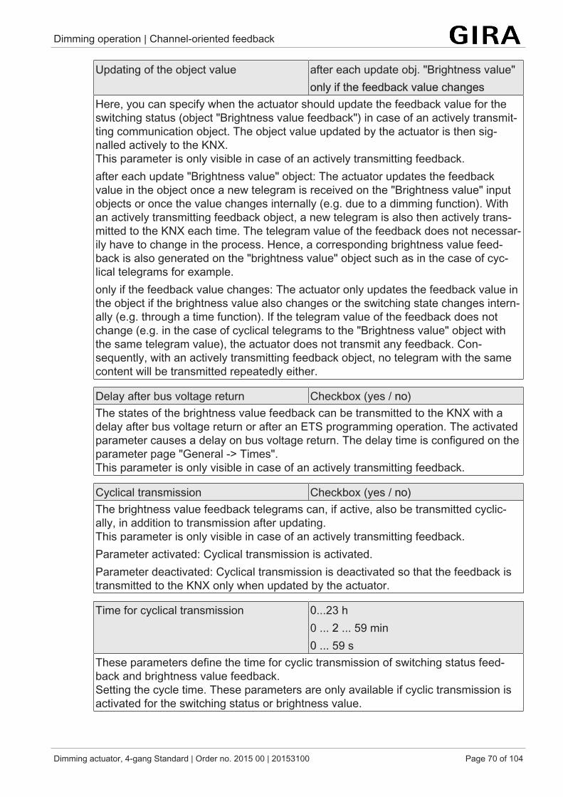
Dimming operation | Channel-oriented feedback
Dimming actuator, 4-gang Standard | Order no. 2015 00 | 20153100 Page 70 of 104
Updating of the object value after each update obj. "Brightness value"only if the feedback value changes
Here, you can specify when the actuator should update the feedback value for theswitching status (object "Brightness value feedback") in case of an actively transmit-ting communication object. The object value updated by the actuator is then sig-nalled actively to the KNX.This parameter is only visible in case of an actively transmitting feedback.after each update "Brightness value" object: The actuator updates the feedbackvalue in the object once a new telegram is received on the "Brightness value" inputobjects or once the value changes internally (e.g. due to a dimming function). Withan actively transmitting feedback object, a new telegram is also then actively trans-mitted to the KNX each time. The telegram value of the feedback does not necessar-ily have to change in the process. Hence, a corresponding brightness value feed-back is also generated on the "brightness value" object such as in the case of cyc-lical telegrams for example.only if the feedback value changes: The actuator only updates the feedback value inthe object if the brightness value also changes or the switching state changes intern-ally (e.g. through a time function). If the telegram value of the feedback does notchange (e.g. in the case of cyclical telegrams to the "Brightness value" object withthe same telegram value), the actuator does not transmit any feedback. Con-sequently, with an actively transmitting feedback object, no telegram with the samecontent will be transmitted repeatedly either.
Delay after bus voltage return Checkbox (yes / no)The states of the brightness value feedback can be transmitted to the KNX with adelay after bus voltage return or after an ETS programming operation. The activatedparameter causes a delay on bus voltage return. The delay time is configured on theparameter page "General -> Times".This parameter is only visible in case of an actively transmitting feedback.
Cyclical transmission Checkbox (yes / no)The brightness value feedback telegrams can, if active, also be transmitted cyclic-ally, in addition to transmission after updating.This parameter is only visible in case of an actively transmitting feedback.Parameter activated: Cyclical transmission is activated.Parameter deactivated: Cyclical transmission is deactivated so that the feedback istransmitted to the KNX only when updated by the actuator.
Time for cyclical transmission 0...23 h0 ... 2 ... 59 min0 ... 59 s
These parameters define the time for cyclic transmission of switching status feed-back and brightness value feedback. Setting the cycle time. These parameters are only available if cyclic transmission isactivated for the switching status or brightness value.

Dimming operation | Channel-oriented feedback
Dimming actuator, 4-gang Standard | Order no. 2015 00 | 20153100 Page 71 of 104
10.10.4 Feedback object list
Object no. Function Name Type DPT Flag32, 52, 72,92
Switching feedback Dimming channel ...(...) - Output
1-bit 1,001 C, R, -, T, A
1-bit object for feedback signalling of the switching state ("1" = on / "0" = off) to thebus.
Object no. Function Name Type DPT Flag36, 56, 76,96
Feedback bright-ness value
Dimming channel ...(...) - Output
1 bytes 5,001 C, R, -, T, A
1-byte object for feedback signalling of an absolute dimming value (brightness value0…255) to the bus.
Object no. Function Name Type DPT Flag191, 197,203, 209
Feedback load type(KNX compliant)
Dimming channel ...(...) - Output
1 bytes 20,610 C, R, -, T, A
1-byte object for signalling the current load type to the bus."0" = undefined"1" = leading edge phase control"2" = trailing edge phase control"3" ... "255" not usedThe object is only available if the parameter "Type of feedback" is set to "Standard(KNX-compliant)".
Object no. Function Name Type DPT Flag192, 198,204, 210
Feedback load type(extended)
Dimming channel ...(...) - Output
1 bytes C, R, -, T, A
1-byte object for signalling the current load type to the bus."0" = undefined (no calibration possible because mains voltage absent / short-circuit)"1" = trailing edge phase control (set by parameter)"2" = leading edge phase control (set by parameter)"3" = universal, adjusted to capacitive or ohmic load"4" = universal, adjusted to inductive load"5" ... "255" not usedThe object is only available if the parameter "Type of feedback" is set to "Extended".
Object no. Function Name Type DPT Flag193, 199,205, 211
Feedback short-cir-cuit
Dimming channel ...(...) - Output
1-bit 1,005 C, R, -, T, A
1-bit object for signalling a short-circuit in relation to the dimming channel ("1" =short-circuit present/"0" = short-circuit not present).

Dimming operation | Channel-oriented feedback
Dimming actuator, 4-gang Standard | Order no. 2015 00 | 20153100 Page 72 of 104
Object no. Function Name Type DPT Flag194, 200,206, 212
Feedback overload /mains voltage fail-ure
Dimming channel ...(...) - Output
1-bit 1,005 C, R, -, T, A
1-bit object for signalling an overload or mains voltage failure in relation to the dim-ming channel ("1" = overload/mains voltage failure present/"0" = overload/mainsvoltage failure not present)

Dimming operation | Time delays
Dimming actuator, 4-gang Standard | Order no. 2015 00 | 20153100 Page 73 of 104
10.11 Time delaysUp to two time functions can be preset for each dimming output, independently ofeach other. The time functions affect the communication objects "Switching" only (ifat least one of the central functions is activated for the output concerned) and delaythe object value received depending on the telegram polarity.
At the end of a disabling function, the switching state received during the func-tion or set before the function can be tracked. At the same time, residual timesof time functions are also tracked if these had not yet fully elapsed at the timeof the reactivation.
The time delays do not influence the staircase function if this is enabled.
A time delay still in progress will be fully aborted by a reset of the actuator (busvoltage failure or ETS programming).
Activating switch-on delay
The switch-on delay can be activated separately in the ETS for each dimming output.
Precondition:The time delays must be enabled on the parameter page "Dimming channel ... ->DO... - General -> Enabled" functions.
■ Set the parameter "Selection of time delay" to "Switch-on delay" or to "Switch-on delay and switch-off delay". Configure the desired switch-on delay.The switch-on delay is enabled. After reception of an ON telegram via the"switching" object, the configurable time is started. Another ON-telegram trig-gers the time only when the parameter "Switch-on delay retriggerable" is activ-ated. An OFF-telegram received during the ON-delay will end the delay andsets the switching status to "OFF".
Activating switch-off delay
The switch-off delay can be activated separately in the ETS for each dimming output.
Precondition:The time delays must be enabled on the parameter page "Dimming channel ... ->DO... - General -> Enabled" functions.
■ Set the parameter "Selection of time delay" to "Switch-off delay" or to "Switch-on delay and switch-off delay". Configure the desired switch-off delay.The switch-off delay is enabled. After reception of an OFF-telegram via the"switching" object, the configurable time is started. Another OFF-telegram trig-gers the time only when the parameter "switch-off delay retriggerable" is activ-ated. An ON-telegram received during the OFF-delay will end the delay andsets the switching status to "ON".

Dimming operation | Time delays
Dimming actuator, 4-gang Standard | Order no. 2015 00 | 20153100 Page 74 of 104
10.11.1 Parameter time delaysDimming channel ... -> DO... - General -> Enabled functions
Time delays Checkbox (yes / no)This parameter can be used to disable or to enable the time delays.The parameter is deactivated if cyclical monitoring is enabled.
Dimming channel ... -> DO... - General -> Time delays
Selection of time delay no time delay
Switch-on delaySwitch-off delayON delay and OFF delay
The communication objects "Switching" can be evaluated after a time delay. By thissetting the desired function of the time delay is selected and the additional paramet-ers of the delay enabled.
Switch-on delay 0…59 min0...10…59
This parameter is used for setting the duration of the switch-on delay.
Switch-on delay retriggerable Checkbox (yes / no)A switch-on delay still in progress can be retriggered by another "ON" telegram(parameter activated). Alternatively, the retriggering time (parameter deactivated)can be suppressed. The parameters for the switch-on delay are only visible if switch-on delay or switch-on and switch-off delay are activated.
Switch-off delay 0…59 min0...10…59
This parameter is used for setting the duration of the switch-off delay.
Switch-off delay retriggerable Checkbox (yes / no)A switch-off delay still in progress can be retriggered (parameter activated) by an-other "OFF" telegram. Alternatively, the retriggering time (parameter deactivated)can be suppressed. The parameters for the switch-off delay are only visible if switch-on delay or switch-on and switch-off delay are activated.

Dimming operation | Scene function
Dimming actuator, 4-gang Standard | Order no. 2015 00 | 20153100 Page 75 of 104
10.12 Scene functionUp to 16 scenes can be programmed and scene values stored separately for eachdimming channel. The scene values are recalled or stored via a separate scene ex-tension object. The data point type of the extension object permits addressing of all64 scenes.
The scene function must be enabled on the parameter page "Dimming channel ... ->DO... - General ->Enabled functions" for each dimming channel in order for the re-quired communication objects and parameters (on the parameter page "Dimmingchannel ... -> DO... - General -> Scenes") to become visible.
The number of scenes used can be selected anywhere in the range 1 to 16. Theparameter "Number of scenes" decides how many scenes are visible for the switch-ing output in the ETS and can therefore be used. It is possible to specify which scenenumber (1 ... 64) controls each scene.
The scene function can be combined together with other functions of a dimmingchannel, whereby the last received or preset state is always executed:Telegrams to the "Switching", "Dimming" or "Brightness value" objects, a scene recallor scene storage telegram at the time of an active staircase function aborts the stair-case time prematurely and presets the brightness state according to the received ob-ject value (delays are also taken into account) or scene value.Similarly, the state of the dimming channel, which was preset by the "Switching","Dimming" or "Brightness value" objects or by a scene recall, can be overridden by astaircase function.
Presetting a scene recall delay
Each scene recall of an dimming channel can optionally also be delayed. With thisfeature, dynamic scene sequences can be configured if several scene outputs arecombined with cyclical scene telegrams.
PreconditionThe scene function must be enabled on the parameter page "Dimming channel ... ->DO... - General -> Enabled functions".
■ on the parameter page "Dimming channel ... -> DO... - General -> Scenes" ac-tivate the parameter "Delay scene recall".The delay time is now activated and can be configured separately. The delayonly influences the scene recall of the dimming channel. The delay time isstarted on arrival of a recall telegram. The corresponding scene will be re-called and the brightness value set on the dimming channel only after this timehas elapsed.
Each scene recall telegram restarts the delay time and retriggers it. If a newscene recall telegram is received while a delay is active (scene recall not yetexecuted), the old (and not yet recalled scene) will be rejected and only thescene last received executed.

Dimming operation | Scene function
Dimming actuator, 4-gang Standard | Order no. 2015 00 | 20153100 Page 76 of 104
The scene recall delay has no influence on the storage of scene values. Ascene storage telegram within a scene recall delay terminates the delay andthus the scene recall.
Presetting the behaviour during ETS programming
During storage of a scene, the brightness values are permanently stored internally inthe device. To prevent the stored values from being replaced during ETS program-ming of the application or of the parameters by the originally programmed scenebrightness values, the actuator can inhibit overwriting of brightness values. As an al-ternative, the original values can be reloaded into the device during each program-ming run of the ETS.
PreconditionThe scene function must be enabled on the parameter page "Dimming channel ... ->DO... - General -> Enabled functions".
■ on the parameter page "Dimming channel ... -> DO... - General -> Scenes",activate the parameter "Overwrite values stored in the device during the ETSprogramming operation".During each ETS programming of the application or of the parameters, thescene brightness values parameterized in the ETS for the dimming channelconcerned will be programmed into the actuator. Any scene brightness valuesstored in the device by means of a storage function will be overwritten.
■ Deactivate the parameter "Overwrite values stored in the device during theETS programming operation".Scene brightness values stored in the device by means of a storage functionwill be maintained. If no scene brightness values have been stored, the bright-ness values last programmed in the ETS remain valid.
When the actuator is commissioned for the first time, this parameter should beactivated so that the brightness values are initialised to valid scene brightnessvalues.
Setting scene numbers and scene switching states
The scene number (1...64) with which the scene is addressed, i.e. recalled or stored,must be determined for each internal scene of the dimming channel. The data pointtype of the scene extension object permits addressing of all scenes.
In addition to specifying the scene number, it is necessary to define which scenecommand (ON, OFF) should be set on the dimming channel during a scene recall.
PreconditionThe scene function must be enabled on the parameter page "Dimming channel ... ->DO... - General -> Enabled functions".
■ On the parameter page "Dimming channel ... -> DO... - General -> Scenes",set the parameter for each scene to the numbers with which the scenes are tobe addressed.

Dimming operation | Scene function
Dimming actuator, 4-gang Standard | Order no. 2015 00 | 20153100 Page 77 of 104
A scene can be addressed with the configured scene number. A setting of "0"deactivates the corresponding scene so that neither recalling nor storage ispossible.
If the same scene number is configured for several scenes, only the scenewith the lowest sequential number will be addressed. The other scenes will beignored in this case.
■ on the parameter page "Dimming channel ... -> DO... - General -> Scenes",set the parameter "Brightness value" to the desired value for each scene.During a scene recall, the parameterized brightness value is recalled and seton the dimming channel.
The parameterized brightness value is adopted in the actuator during pro-gramming with the ETS only if the parameter "Overwrite values stored in thedevice during ETS download" is activated.
Presetting storage behaviour
The switching state set for the dimming channel can be stored internally via the ex-tension object on receipt of a scene storage telegram. In this case, the switchingstate can be influenced before the storage by all functions of the dimming channel,provided that the individual functions have been enabled (e.g. also the disabling func-tion, forced position function etc.).
PreconditionThe scene function must be enabled on the parameter page "Dimming channel ... ->DO... - General -> Enabled functions".
■ on the parameter page "Dimming channel ... -> DO... - General -> Scenes" ac-tivate the parameter "storage function" for each scene.The storage function is activated for the scene in question. On reception of astorage telegram via the "Scene extension" object, the current switching statewill be internally stored.
■ Deactivate the parameter "storage function" for each scene.The storage function is deactivated for the scene in question. A storage tele-gram received via the "scene extension" object will be rejected.

Dimming operation | Scene function
Dimming actuator, 4-gang Standard | Order no. 2015 00 | 20153100 Page 78 of 104
10.12.1 Parameter scene functionDimming channel ... -> DO... - General -> Enabled functions
Scene function Checkbox (yes / no)This parameter can be used disable or to enable the scene function.The parameter is deactivated if cyclical monitoring is enabled.
Dimming channel ... -> DO... - General: -> Scenes
Delay scene recall Checkbox (yes / no)A scene is recalled via the scene extension object. If required, the scene recall canbe delayed on reception of a recall telegram (parameter activated). The recall is al-ternatively made immediately on reception of the telegram (parameter deactivated)
Delay time 0...59 min0...10...59 s
These parameters specify the duration of the scene delay time.
On scene request Jumping to brightness valueDimming to brightness value via dimmingincrem. timeDimming brightness value via fading
When recalling a scene, the configured or stored scene value is set for the dimmingchannel concerned. This parameter setting can define whether the brightness valuecan be instantly jumped to or dimmed to or is set via fading. When fading, the bright-ness value to be set is reached in the exact configured fading time irrespective of thedimming characteristic of a channel and irrespective of which brightness value thedimming procedure was started at. Thus, for example, several dimming channelscan be set to the same brightness at the same time.
Dimming increment time 0 ... 5… 255 msSetting of the dimming increment time if the brightness value of a scene should bedimmed. This parameter is visible only if the parameter "Behaviour when recalling ascene" is set to "Dim to brightness value via dimming increment time".
Time for brightness value via fading 0 ... 2 ... 240 sSetting of the fading time if the brightness value of a scene should be dimmed to viafading. This parameter is visible only if the parameter "behaviour when recalling ascene" is set to "dim to brightness value via fading".

Dimming operation | Scene function
Dimming actuator, 4-gang Standard | Order no. 2015 00 | 20153100 Page 79 of 104
Visual feedback for storage function Checkbox (yes / no)Optionally, a visual feedback via the dimming output can be signaled when execut-ing a storage command. The channel flashes once as feedback in the configuredflashing time.Parameter activated: When a storage function is executed, the visual feedback is ac-tivated immediately. The output switches to the opposite switching state for the dura-tion of the configured flashing time and then back to the saved scene command.Parameter deactivated: When storing a scene, the visual feedback is not executed.The actuator adopts the current state of the output without special feedback.
Flashing time (0...10) 0...5...10The flashing time in which the visual feedback is to be executed is set here.This parameter is only visible when visual feedback is used.
Overwrite values stored in the device dur-ing the ETS programming operation
Checkbox (yes / no)
During storage of a scene, the scene values (current states of the dimming outputsconcerned) are stored internally in the device. To prevent the stored values from be-ing replaced during ETS programming by the originally programmed scene values,the actuator can inhibit overwriting of the scene values (parameter deactivated). Asan alternative, the original values can be reloaded into the device during each pro-gramming run of the ETS (parameter activated).
Number of scenes (1...16) 1...10...16This parameter defines how many scenes are visible for the dimming channel in theETS and can therefore be used.
Scene number 0...1*...64*: The predefined scene number is de-pendent on the scene (1...64).
The number of scenes used can be selected anywhere in the range 1 to 16. It isthen possible to preset which scene number (1 ... 64) controls each scene.A setting of "0" deactivates the corresponding scene so that neither recalling norstorage is possible. If the same scene number is configured for several scenes, onlythe scene with the lowest sequential number will be addressed. The other sceneswill be ignored in this case.
brightness value switch offBasic brightness5 %...100 %
This parameter is used for configuring the value which is set when the scene is re-called.

Dimming operation | Scene function
Dimming actuator, 4-gang Standard | Order no. 2015 00 | 20153100 Page 80 of 104
Memory function Checkbox (yes / no)If the parameter is activated, the storage function of the scene is enabled. The cur-rent switching state can then be stored internally via the extension object on receiptof a storage telegram. If the parameter is deactivated, the storage telegrams are re-jected.

Dimming operation | Scene function
Dimming actuator, 4-gang Standard | Order no. 2015 00 | 20153100 Page 81 of 104
10.12.2 Object list scene function
Object no. Function Name Type DPT Flag38, 58, 78,98
Scene extension Switching... - Input 1 bytes 18,001 C, (R), W, -,A
1-byte object for polling or saving a scene.

Dimming operation | Staircase function
Dimming actuator, 4-gang Standard | Order no. 2015 00 | 20153100 Page 82 of 104
10.13 Staircase functionThe staircase function can be used for implementing time-controlled lighting of astaircase or for function-related applications. The staircase function must be enabledin the ETS on the parameter page "Dimming channel ... -> DO... - General -> En-abled functions", in order for the required communication objects and parameters tobe visible.
The staircase function is activated via the communication object "staircase functionstart / stop" and is independent of the "switching" object of a dimming channel. In thisway, parallel operation of time and normal control is possible, whereby the commandlast received is always executed: A telegram to the "switching" object or a scene re-call at the time of an active staircase function aborts the staircase time prematurelyand presets the switching state according to the received object value (the timedelays are also taken into account) or scene value. Likewise, the switching state ofthe "switching" object can be overridden by a staircase function.
Time-independent continuous light switching can also be implemented in combina-tion with a disabling function because the disabling function has a higher priority andoverrides the switching state of the staircase function.Furthermore, an extension of the staircase function can be implemented by means ofa separate switch-on delay and pre-warning function. The pre-warning should, ac-cording to DIN 18015-2, warn any person still on the staircase that the light will soonbe switched off. As an alternative to the pre-warning at the end of the staircase time,the actuator can activate reduced continuous lighting. In this way, for example, long,dark hallways can have permanent basic lighting.
Specifying switch-on behaviour of the staircase function
An ON telegram to the "Staircase function start/stop" object activates the staircasetime (TON), the duration of which is defined by the parameters"Staircase time". In ad-dition, a switch-on delay (TDelay) can be activated (see "presetting switch-on delay ofthe staircase function"). At the end of the staircase time, the output switches off oractivates optionally the pre-warning time (TPrewarn) of the pre-warning function (see"presetting pre-warning function of the staircase function"). Taking into account anypossible switch-on delay and pre-warning function, this gives rise to the switch-on be-haviour of the staircase function as shown in the following diagram.
Image 12: Switch-on behaviour of the staircase function

Dimming operation | Staircase function
Dimming actuator, 4-gang Standard | Order no. 2015 00 | 20153100 Page 83 of 104
The parameter "Staircase time retriggerable" specifies whether the staircase time canbe retriggered.
Precondition:The staircase function must be enabled on the parameter page "Dimming channel ...-> DO... - General -> Enabled functions".
■ In the parameter "Staircase time" on the parameter page "Dimming channel ...-> DO... - General -> Staircase function", configure the required switch-on timeof the staircase function.
■ Activate parameter "Staircase time retriggerable".Every ON telegram received during the ON phase of the staircase time retrig-gers the staircase time completely.
■ Deactivate parameter "Staircase time retriggerable".ON telegrams received during the ON phase of the staircase time are rejected.The staircase time is not retriggered.
An ON telegram received during the pre-warning time always retriggers thestaircase time independently of the parameter "Staircase time retriggerable".
Specifying switch-off behaviour of the staircase function
In the case of a staircase function, the reaction to an OFF telegram can also be con-figured on the object "staircase function start/stop". At the end of the staircase time, adimming channel always shows the reaction "At the end of the staircase time" con-figured in the ETS, without the receipt of an OFF telegram. At the same time, thechannel can switch off, optionally activate the pre-warning time (TVorwarn) of thepre-warning function or dim to the reduced continuous lighting (application: e.g. long,dark hallways). If, on the other hand, the dimming channel receives an OFF telegramvia the object "Staircase function start/stop", the actuator evaluates the parameter"Reaction to an OFF-telegram". In this case, the channel can react immediately to theOFF telegram and end the staircase time prematurely. Alternatively, the OFF tele-gram can be ignored. Taking into account any possible pre-warning function, thisgives rise to the example switch-off behaviour of the staircase function.
Image 13: Switch-off behaviour of the staircase function
The parameter "reaction to OFF-telegram" defines whether the staircase time (TON) ofthe staircase function can be aborted prematurely.

Dimming operation | Staircase function
Dimming actuator, 4-gang Standard | Order no. 2015 00 | 20153100 Page 84 of 104
Precondition:The staircase function must be enabled on the parameter page "Dimming channel ...-> DO... - General -> Enabled functions".
■ Set parameter "Reaction to OFF-telegram" to "switch off".As soon as an OFF telegram is received via the object"Staircase function start/stop" during the ON phase of the staircase time, theoutput switches off immediately. If the staircase time is stopped prematurelyby such a telegram, there is no pre-warning, i.e. the pre-warning time is notstarted. There is also no dimming to a reduced continuous lighting. It is alsopossible to switch off prematurely during a dimming procedure of a soft func-tion or during a pre-warning or reduced continuous lighting.
■ Set parameter "Reaction to OFF-telegram" to ignore".OFF telegrams received during the ON phase of the staircase time are rejec-ted. The staircase time will be executed completely to the end with pre-warn-ing if necessary.
The parameter "Reaction to OFF telegram" does not influence the receptionand the evaluation of OFF telegrams via the "Switching" object.
Setting the switch-on delay of the staircase function
An ON telegram for activation of the staircase function can also be evaluated with atime delay. This switch-on delay can be activated separately for the staircase func-tion and has no influence on the configurable time delays for the object "switching".
Precondition:The staircase function must be enabled on the parameter page "Dimming channel ...-> DO... - General -> Enabled functions".
■ on the parameter page "Dimming channel ... -> DO... - General -> Staircasefunction" deactivate the parameter "Switch-on delay".The switch-on delay is deactivated. After reception of an ON telegram on theobject "Staircase function start/stop", the staircase time is activated immedi-ately and the output switched on.
■ Activate the parameter "switch-on delay".The switch-on delay for the staircase function is enabled. The desired switch-on delay time can be specified. After reception of an ON telegram on theobject "Staircase function start/stop", the switch-on delay is started. AnotherON-telegram triggers the time only when the parameter"Switch-on delay retriggerable" is activated. The staircase time is activatedand the output is switched on only after the time delay has elapsed.
An OFF telegram via the object "Staircase function start/stop" during theswitch-on delay only terminates the delay if the parameter "Reaction to OFF-telegram" is set to "switch off". Otherwise, the OFF telegram is ignored.

Dimming operation | Staircase function
Dimming actuator, 4-gang Standard | Order no. 2015 00 | 20153100 Page 85 of 104
Setting the pre-warning function of the staircase function
At the end of the switch-on time of the staircase function, the actuator for the dim-ming channel concerned shows the reaction "At the end of the staircase time" con-figured in the ETS. The channel can be set to switch off immediately, alternatively todim to the reduced continuous lighting (application: e.g. long, dark hallways) or to ex-ecute the pre-warning function. If the parameter is configured to "activate pre-warningtime", the pre-warning time (TVorwarn) and pre-warning brightness can be con-figured in the ETS.
The pre-warning should, according to DIN 18015-2, warn persons still on the stair-case that the light will soon be switched off. As a pre-warning, a dimming channelcan be set to a pre-warning brightness before the channel switches off permanently.The pre-warning brightness is normally reduced in the brightness value compared tothe switch-on brightness. The pre-warning time is added to the staircase time (TON).The pre-warning time influences the value of the feedback object so that the value"OFF" (in the case of non-inverted transmission) is first tracked after the pre-warningtime in the object has elapsed.
Image 14: The pre-warning function of the staircase function without soft OFF func-tion
Additionally, the pre-warning function can also be extended by the soft OFF function.Taking into account any soft OFF function, this gives rise to a modified switch-off be-haviour of the staircase function after the pre-warning has elapsed.
Image 15: The pre-warning function of the staircase function with soft OFF function(as an example with minimum brightness = 0%)

Dimming operation | Staircase function
Dimming actuator, 4-gang Standard | Order no. 2015 00 | 20153100 Page 86 of 104
Precondition:The staircase function must be enabled on the parameter page "Dimming channel ...-> DO... - General -> Enabled functions".
■ on the parameter page "Dimming channel ... -> DO... - General -> Staircasefunction" set the parameter "At the end of the staircase time" to "activate pre-warning time".The pre-warning function is enabled. The desired pre-warning time (TPrewarn)can be preset.
■ Set the parameter "Reduced brightness" to the desired value.During the pre-warning time, the dimming channel is set to the configuredbrightness value.
The configured value for the reduced brightness must be greater than or equalto the minimum brightness (if configured) or less than or equal to the max-imum brightness!
An ON telegram to the object "Staircase function start/stop" while a pre-warn-ing function is still in progress stops the pre-warning time and always restartsthe staircase time (independently of the parameter "Staircase time retrigger-able"). Even during the pre-warning time, the parameter "reaction to OFF tele-gram" is evaluated so that a pre-warning in progress can be terminated earlyby switching off.
An ON telegram to the object "Staircase function start/stop" while a pre-warn-ing function is still in progress stops the pre-warning time and always starts(independently of the parameter "Staircase time retriggerable ?") the staircasetime anew. Even during the pre-warning time, the parameter "reaction to OFFtelegram" is evaluated so that a pre-warning in progress can be terminatedearly by switching off.
Using the automatic switch-off function: The reduced brightness of the pre-warning does not start the switch-off function after reaching or undershootingthe switch-off brightness!
Setting continuous lighting of the staircase function
At the end of the switch-on time of the staircase function, the actuator for the dim-ming channel concerned shows the "reaction at the end of the staircase time" con-figured in the ETS. The channel can be set to switch off immediately, alternatively toexecute a pre-warning function, or to dim to reduced continuous lighting. The reduc-tion of the lighting to continuous lighting after the staircase time has elapsed is appro-priate, for example, if a certain degree of artificial light should be switched on per-manently in long, dark hallways. Switching to switch-on brightness by activating thestaircase function normally takes place by additional presence detectors or motiondetectors when people are present in the hallway.

Dimming operation | Staircase function
Dimming actuator, 4-gang Standard | Order no. 2015 00 | 20153100 Page 87 of 104
If the parameter "Reaction at the end of the staircase time" is configured to "activatereduced continuous lighting", the brightness for the continuous lighting can be con-figured in the ETS. The continuous brightness is normally reduced in the brightnessvalue compared to the switch-on brightness.
The continuous lighting remains permanently active after the staircase time haselapsed. Only when an ON telegram is received again via the object "Staircase func-tion start/stop" does the actuator switch back to the switch-on brightness and startcounting the staircase time again. The receipt of an OFF telegram via the object"staircase function start/stop" only switches the continuous lighting off if the para-meter "Reaction to OFF-telegram" is configured to "switch off".
A dimming channel can always be switched on and off via the "switching" ob-ject independently of the staircase function. Consequently, continuous lightingwill also be overridden if telegrams arrive on the actuator via the "switching"object. If permanent continuous lighting is desired, which cannot be influencedby the "switching" object nor by the object of the staircase function, the dis-abling function of the actuator should be used.
Image 16: The continuous lighting of the staircase function without soft functions
Additionally, the continuous lighting can also be extended by the soft function. Takinginto account any soft ON and soft OFF function, this gives rise to modified continuouslighting behaviour of the staircase function.

Dimming operation | Staircase function
Dimming actuator, 4-gang Standard | Order no. 2015 00 | 20153100 Page 88 of 104
Image 17: The continuous lighting of the staircase function with soft OFF functions
The brightness of the continuous lighting does not necessarily have to be lessthan the switch-on brightness. The brightness of the continuous lighting can al-ways be configured to values between basic/minimum brightness and max-imum brightness.
Precondition:The staircase function must be enabled on the parameter page "Dimming channel ...-> DO... - General -> Enabled functions".
■ on the parameter page "Dimming channel ... -> DO... - General -> Staircasefunction", set the parameter "At end of the staircase time" to "Activate reducedcontinuous lighting".The continuous lighting is enabled. The "Reduced brightness" can be set tothe desired brightness value.
The configured value for the reduced brightness must be greater than or equalto the minimum brightness (if configured) or less than or equal to the max-imum brightness!
An ON telegram to the object "Staircase function start/stop" while a pre-warn-ing function is still in progress stops the pre-warning time and always restartsthe staircase time (independently of the parameter "Staircase time retrigger-able"). Even during activated continuous lighting, the parameter "Reaction toOFF telegram" is evaluated so that continuous lighting can be switched off.
Using the automatic switch-off function: The reduced brightness of the continu-ous lighting does not start the switch-off function after reaching or undershoot-ing the switch-off brightness!
Setting the behaviour of the staircase function after bus voltage return
The staircase function can optionally be started automatically after bus voltage re-turn.

Dimming operation | Staircase function
Dimming actuator, 4-gang Standard | Order no. 2015 00 | 20153100 Page 89 of 104
Precondition:The staircase function must be enabled on the parameter page "Dimming channel ...-> DO... - General -> Enabled functions".
■ on the parameter page "Dimming channel ... -> DO... - General", set the para-meter "After bus voltage return" to "Activate staircase function".Immediately after bus voltage return, the staircase time of the staircase func-tion is started.
During automatic starting of the staircase function after bus voltage return, noswitch-on delay is started if the staircase function has configured such a delay.
The device only executes the configured "Behaviour on bus voltage return"only if the last ETS programming of the application or of the parameters endedat least approx. 20 s prior to switching on the bus voltage. Otherwise(TETS < 20 s) the behaviour "after ETS programming" will be adopted also incase of bus voltage return.
The configured behaviour will only be executed, if no forced position on busvoltage return is activated.

Dimming operation | Staircase function
Dimming actuator, 4-gang Standard | Order no. 2015 00 | 20153100 Page 90 of 104
10.13.1 Parameter Staircase functionDimming channel ... -> DO... - General -> Enabled functions
Staircase function/logic operation function no selectionStaircase functionLogic operation function
This parameter determines whether the staircase function or alternatively the logicoperation function is available for the dimming channel.
Dimming channel ... -> DO... - General -> Staircase function
Staircase time 0...23 h0...3...590...59
This parameter is used for programming the duration of the switch-on time for ascene recall.
Staircase time retriggerable Checkbox (yes / no)An active switch-on time can be retriggered (parameter activated). Alternatively, theretriggering time (parameter deactivated) can be suppressed.This parameter is preset to deactivated if the supplementary function "Time exten-sion" is configured. Re-triggering will not be possible.
Switch-on delay Checkbox (yes / no)The staircase function enables the activation of an own switch-on delay. This switch-on delay affects the trigger result of the staircase function and thus delays theswitch-on.activated: The switch-on delay for the staircase function is enabled. After receptionof an ON telegram on the object "Staircase function start/stop", the switch-on delayis started. Another ON-telegram triggers the time only when the parameter "Switch-on delay retriggerable" is activated. The staircase time is activated and the output isswitched on only after the time delay has elapsed.deactivated: The switch-on delay is deactivated. After reception of an ON telegramon the object "Staircase function start/stop", the staircase time is activated immedi-ately and the output switched on.
Switch-on delay 0...23 h0...3...590...59
This parameter is used for setting the duration of the switch-on delay. Sets theswitch-on delay hours.

Dimming operation | Staircase function
Dimming actuator, 4-gang Standard | Order no. 2015 00 | 20153100 Page 91 of 104
Switch-on delay retriggerable Checkbox (yes / no)An active switch-on delay can be retriggered (parameter activated). Alternatively, theretriggering time (parameter deactivated) can be suppressed.This parameter is deactivated if the supplementary function "Time extension" is con-figured. Re-triggering will not be possible.The parameters for the switch-on delay are only visible when the switch-on delay isused.
Reaction to OFF-telegram switch offignore
An active switch-on time can be aborted prematurely by switching off the staircasefunction.switch off: The switch-on time is aborted after receipt of an OFF telegram on the ob-ject "Staircase time start/stop".With the supplementary function "time preset via the bus" and the setting "Staircasefunction activatable via object 'Staircase time' = activated" the switch-on time canalso be prematurely ended by a factor of "0".ignore: OFF Telegrams or "0" factors are ignored. The switch-on time will be ex-ecuted completely to the end.
At the end of the staircase time switch offactivate pre-warning timeactivate reduced continuous lighting
At the end of the staircase time, the actuator for the dimming channel concerned dis-plays the configured behaviour here. The output can be set to switch off immediatelyor alternatively to execute a pre-warning function.switch off: At the end of the staircase time, the actuator switches off the dimmingchannel concerned.Activate pre-warning time: At the end of the staircase time, the dimming channel cangenerate a pre-warning prior to switch-off. The pre-warning, for example, shouldwarn any person still on the staircase that the light will soon be switched off.Activate reduced continuous lighting: At the end of the switch-on time, the actuatoractivates reduced continuous lighting for the dimming channel concerned. The re-duction of the lighting to continuous lighting is appropriate, for example, if a certaindegree of artificial light should be switched on permanently in long, dark hallways.Switching to switch-on brightness by activating the staircase function normally takesplace by additional presence detectors or motion detectors when people are presentin the hallway. The continuous lighting remains permanently active after the switch-on time has elapsed. Only when an ON telegram is received again via the object"Staircase function start/stop" does the actuator switch back to the switch-on bright-ness and start counting the switch-on time again.

Dimming operation | Staircase function
Dimming actuator, 4-gang Standard | Order no. 2015 00 | 20153100 Page 92 of 104
Pre-warning time 0...59 min0...30...59 s
This parameter is used for setting the duration of the pre-warning time. The pre-warning time is added to the switch-on time.
Reduced brightness Basic brightness5 %...50 %...100 %
This parameter defines the reduced brightness that is set either for pre-warning orcontinuous lighting.

Dimming operation | Staircase function
Dimming actuator, 4-gang Standard | Order no. 2015 00 | 20153100 Page 93 of 104
10.13.2 Object list staircase function
Object no. Function Name Type DPT Flag41, 61, 81,101
Staircase functionstart/stop
Switching... - Input 1-bit 1,010 C, (R), W, -,A
1-bit object to activate or deactivate the switch-on time of the staircase function of adimming output ("1" = switch-on / "0" = switch-off).

Dimming operation | Logic operation function
Dimming actuator, 4-gang Standard | Order no. 2015 00 | 20153100 Page 94 of 104
10.14 Logic operation functionA logic function can be parameterized separately for each dimming channel. Thisfunction allows the logic operation of the "Switching" object state and an additional lo-gic operation object. The state of the communication object for "switching" can alsobe evaluated with a time delay if a switch-on delay or switch-off delay is set.The logic operation function can also be combined with other functions of a dimmingchannel. A combination with the staircase function is not possible, however.
Image 18: Logic operation types of the logic operation function
"AND with feedback":With a logic object = "0", the switching output is always "0" (logic AND). In thiscase, the feedback signal from the output to the "switching" input will directlyreset this input when it is being set. The output of the switching output can as-sume the logical state "1" by a newly received "1" on the input "switching" onlywhen the logic object is = "1".
The object "Logic operation" can be initialised with a configured value after busvoltage return or after an ETS programming operation so that a correct logic opera-tion result can be determined immediately and set on the output during a telegramupdate on the "Switching" object.
■ On the parameter page "Dimming channel ... -> DO... - General -> Enabledfunctions" activate the "logic operation function".The logic operation function is enabled. The communication object "logic oper-ation" and the parameters of the logic operation function on the parameterpage "Dimming channel ... -> DO... - General -> Logic operation function" be-come visible.
■ Set the parameter "Type of logic operation function" to the desired logic opera-tion type.
■ Set the parameters "object value after bus voltage return" and "object valueafter ETS programming" to the required initial states.The "logic operation" object is initialised immediately with the set switchingstates after bus voltage return or ETS programming of the application programor parameters.
The logic operation function after a reset of the actuator (bus voltage return orETS programming operation) is first executed when the switching object is up-dated as the input of the logic operation by at least one telegram.
The states or switching states specified at the end of a disabling function,which are set after programming in the ETS, in the case of bus voltage failureor after bus or mains voltage return, override the logic operation function. The

Dimming operation | Logic operation function
Dimming actuator, 4-gang Standard | Order no. 2015 00 | 20153100 Page 95 of 104
configured logic operation is first re-executed and the result set on the switch-ing output when the switching object is updated as the input of the logic opera-tion by at least one telegram.

Dimming operation | Logic operation function
Dimming actuator, 4-gang Standard | Order no. 2015 00 | 20153100 Page 96 of 104
10.14.1 Parameter logic operation functionDimming channel ... -> DO... - General -> Enabled functions
Staircase function/logic operation function no selectionStaircase functionLogic operation function
The staircase function or the logic operation function or can be enabled or disabledhere.
Dimming channel ... -> DO... - General -> Logic operation function
Type of logic operation function ORANDAND with feedback
This parameter defines the logical type of the logic operation function. The object "lo-gic operation" is linked to the logic switching state of the dimming channel (object"switching" after evaluation of configured time delays if necessary) using the logicoperation function set here.This parameter is only visible when the logic operation function is enabled.
Object value after bus voltage return 0 (OFF)1 (ON)
After bus voltage return, the object value of the logic operation object is initialisedhere with the preset value.This parameter is only visible when the logic operation function is enabled.
Object value after ETS download 0 (OFF)1 (ON)
After programming the application or the parameters in the ETS, the object value ofthe logic operation object is initialised here with the preset value.This parameter is only visible when the logic operation function is enabled.

Dimming operation | Logic operation function
Dimming actuator, 4-gang Standard | Order no. 2015 00 | 20153100 Page 97 of 104
10.14.2 Object list logic operation function
Object no. Function Name Type DPT Flag33, 53, 73,93
Logic operation Switching... - Input 1-bit 1,002 C, (R), W, -,A
1-bit object for the input of the logical operation of a dimming channel. After busvoltage return or after programming with the ETS, the object value can be pre-defined for each parameter.

Dimming operation | disabling function
Dimming actuator, 4-gang Standard | Order no. 2015 00 | 20153100 Page 98 of 104
10.15 disabling function
Setting disabling function as supplementary function
During an active disabling function, the KNX control of the dimming function con-cerned is overridden and locked. Continuous light switching, for example, can also beoverridden. The deactivation of the disabling function can optionally take place usingan additional 1-bit acknowledgement object. This prevents the deactivation of the dis-abling function by the disabling object.
■ On the parameter page "Dimming channel ... -> DO... - General -> DA... - En-abled functions" activate the parameter "Disabling function".The disabling function is enabled. The communication object "Disable" and theparameters of the disabling function on the parameter page "Dimming chan-nel ... -> DO... - General -> DA... - Disabling function" become visible.
■ Set the parameter "Polarity disabling object" to the desired polarity.■ Set the parameter "Beginning of the disabling function" to the required beha-
viour.At the beginning of the disabling function, the configured behaviour will be ex-ecuted and the bus control of the dimming channel locked.
With the "Switch off" setting, the output is switched off and remains in thisstate.
With the "Brightness value" setting, the channel sets the specified brightnessvalue and remains in this brightness state.
The "Memory value (brightness value before last switch-off)" setting is used toset the brightness value that was active and internally stored before the lastswitch-off (via the "Switching" or "Central switching" object). After program-ming with the ETS, the value is predefined to maximum brightness. Only a busvoltage failure, however, does not delete the memory value.
In the "no reaction" setting, the dimming channel shows no response and re-mains in the brightness state last selected.
In the "flashing" setting, the dimming channel is switched on and off cyclicallyduring the disabling. The "Time for flashing of the disabling functions" is gener-ally configured on the parameter page "General -> Times". During flashing, thelogical switching state of the dimming channel is signalled back as "switchedon" and the brightness value as "switch-on brightness". A soft ON/OFF func-tion is not executed during flashing.
Behaviour at the end of disabling ...
The disabling function is deactivated by the disabling object according to the set po-larity.
■ Set the parameter "End of the disabling function" to the required behaviour.
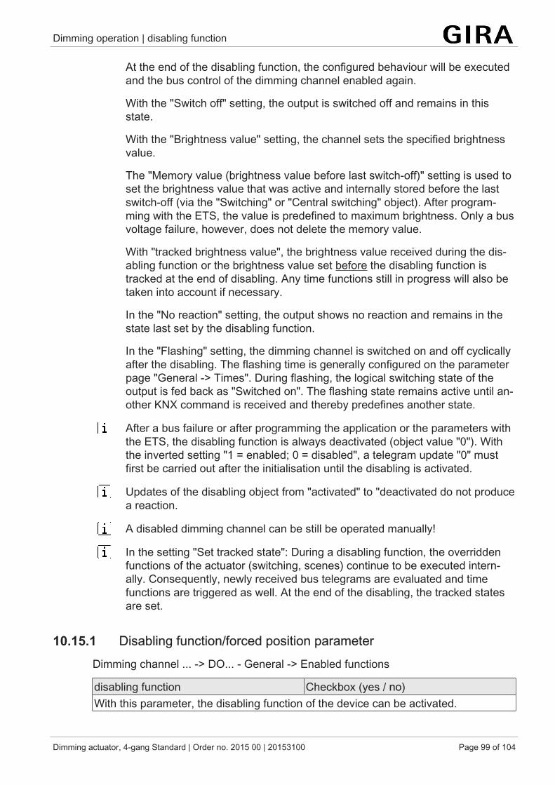
Dimming operation | disabling function
Dimming actuator, 4-gang Standard | Order no. 2015 00 | 20153100 Page 99 of 104
At the end of the disabling function, the configured behaviour will be executedand the bus control of the dimming channel enabled again.
With the "Switch off" setting, the output is switched off and remains in thisstate.
With the "Brightness value" setting, the channel sets the specified brightnessvalue.
The "Memory value (brightness value before last switch-off)" setting is used toset the brightness value that was active and internally stored before the lastswitch-off (via the "Switching" or "Central switching" object). After program-ming with the ETS, the value is predefined to maximum brightness. Only a busvoltage failure, however, does not delete the memory value.
With "tracked brightness value", the brightness value received during the dis-abling function or the brightness value set before the disabling function istracked at the end of disabling. Any time functions still in progress will also betaken into account if necessary.
In the "No reaction" setting, the output shows no reaction and remains in thestate last set by the disabling function.
In the "Flashing" setting, the dimming channel is switched on and off cyclicallyafter the disabling. The flashing time is generally configured on the parameterpage "General -> Times". During flashing, the logical switching state of theoutput is fed back as "Switched on". The flashing state remains active until an-other KNX command is received and thereby predefines another state.
After a bus failure or after programming the application or the parameters withthe ETS, the disabling function is always deactivated (object value "0"). Withthe inverted setting "1 = enabled; 0 = disabled", a telegram update "0" mustfirst be carried out after the initialisation until the disabling is activated.
Updates of the disabling object from "activated" to "deactivated do not producea reaction.
A disabled dimming channel can be still be operated manually!
In the setting "Set tracked state": During a disabling function, the overriddenfunctions of the actuator (switching, scenes) continue to be executed intern-ally. Consequently, newly received bus telegrams are evaluated and timefunctions are triggered as well. At the end of the disabling, the tracked statesare set.
10.15.1 Disabling function/forced position parameterDimming channel ... -> DO... - General -> Enabled functions
disabling function Checkbox (yes / no)With this parameter, the disabling function of the device can be activated.

Dimming operation | disabling function
Dimming actuator, 4-gang Standard | Order no. 2015 00 | 20153100 Page 100 of 104
Dimming channel ... -> DO... - General -> Disabling function
Polarity of the disabling object 0 = disabled;1 = enabled1 = enabled;0 = disabled
This parameter defines the polarity of the disabling object.This parameter is visible only if the disabling function is enabled.
Beginning of the disabling function switch offbrightness valueMemory value (brightn. bef. switch. offlast time)no reactionflashing
The behaviour of the dimming output at the beginning of the disabling function canbe configured.This parameter is visible only if the disabling function is enabled.Switch off: At the start of the disabling function, the dimming output is switched offand locked.Brightness value: At the start of the disabling function, the dimming channel is set tothe predefined brightness value and locked.Memory value: At the start of the disabling function, the active and internally savedvalue prior to the last switch-off is set (via the "Switching" or "Central switching" ob-ject).No reaction: At the start of a disabling function, the dimming channel shows no reac-tion and remains in the currently set state. Bus control of the dimming channel isthen locked.Switch on: At the start of the disabling function, the dimming channel is switched onand locked.Flashing: The dimming channel flashes on and off during the disabling function andthe bus control is locked during this time. The flashing time is configured generallyfor all channels on the parameter page "General". During the flashing, the logicalswitching state is "on 1" and the switch-on brightness is signalled back as bright-ness. A soft ON/OFF function is ignored during flashing.

Dimming operation | disabling function
Dimming actuator, 4-gang Standard | Order no. 2015 00 | 20153100 Page 101 of 104
End of the disabling function switch offbrightness valueMemory value (brightn. bef. switch. offlast time)tracked brightness valueno reactionflashing
The behaviour of the dimming output at the end of the disabling function can be con-figured.This parameter is visible only if the disabling function is enabled and acknowledge-ment is not used.Switch off: At the end of the disabling function, the dimming output is switched offand enabled again.Brightness value: At the end of the disabling function, the dimming channel is set tothe predefined brightness value and enabled again.Memory value: At the end of disabling, the active and internally stored brightnessvalue prior to the last switch-off is set (via the "Switching" or "Central switching" ob-ject).tracked brightness value: At the end of the disabling function, the state received dur-ing the disabling function or the state set before the disabling function is tracked withthe appropriate brightness value. Any time functions still in progress will also betaken into account if necessary.No reaction: At the end of a disabling function, the dimming channel shows no reac-tion and remains in the currently set state. Bus control of the dimming channel is en-abled again.Flashing: The dimming channel is enabled again for the bus control after the end ofthe disabling function and flashes on and off. The flashing time is configured gener-ally for all channels on the parameter page "General". During the flashing, the logicalswitching state is "on 1" and the switch-on brightness is signalled back as bright-ness. A soft ON/OFF function is ignored during flashing. The flashing status remainsactive until another bus command is received and specifies another status.

Dimming operation | disabling function
Dimming actuator, 4-gang Standard | Order no. 2015 00 | 20153100 Page 102 of 104
10.15.2 Disabling function/forced position object list
Object no. Function Name Type DPT Flag39, 59, 79,99
Disabling Dimming channel ...- Input
1-bit 1,003 C, (R), W, -,A
1-bit object for disabling a dimming channel (polarity configurable).

Delivery state
Dimming actuator, 4-gang Standard | Order no. 2015 00 | 20153100 Page 103 of 104
11 Delivery stateIn the as-delivered state, the actuator is passive, i.e. no telegrams are transmitted tothe KNX. All dimming channels are set to the universal dimming principle with auto-matic recognition of the load type. The outputs can, however, be activated by manualoperation on the device, if the bus voltage is on. In the manual control mode, nofeedback telegrams are sent to the KNX.The device can be programmed and put into operation via the ETS. The physical ad-dress is preset to 15.15.255
Moreover the device has been configured at the factory with the following character-istics...
– Behaviour in case of bus voltage failure: no reaction– Behaviour in case of bus voltage return: brightness before bus voltage failure– Status indication: permanent
The as-delivered state cannot be restored by unloading the application pro-gram with the aid of the ETS. When the application program is removed, allthe outputs remain permanently switched off. The manual operation remainswithout function in this case.

Contact
Dimming actuator, 4-gang Standard | Order no. 2015 00 | 20153100 Page 104 of 104
GiraGiersiepen GmbH & Co. KGElektro-Installations-Systeme
Industriegebiet MermbachDahlienstraße42477 Radevormwald
Postfach 12 2042461 Radevormwald
Deutschland
Tel +49(0)21 95 - 602-0Fax +49(0)21 95 - 602-191