dio5518d 300ma single li-ion battery charger · icharge vs. ambient temperature i trickle charge...
TRANSCRIPT
Rev 1.1
www.dioo.com © 2018 DIOO MICROCIRCUITS CO., LTD DIO5518D• Rev. 1.1
DIO5518D 300mA,Single Li-ion Battery Charger
Features Programmable Charge Current Up to 300mA
Over-Temperature Protection
Under Voltage Lockout Protection
Over Voltage Lockout Protection
Reverse current protection between BAT and
GND pins
Automatic Recharge Threshold 4.05V(Typ.)
Charge Status Output Pin
2.9V Trickle Charge Threshold
Soft-Start Limits Inrush Current
Applications Wireless phone
MP3/MP4 Player
Bluetooth device
Descriptions The DIO5518D is a complete constant-current /
constant voltage linear charger for single cell
Lithium-Ion batteries. No external sense resistor
is needed, and no blocking diode is required due
to the internal MOSFET architecture. Thermal
feedback regulates the charge current to limit the
die temperature during high power operation or
high ambient temperature. The charge voltage is
fixed at 4.2V, and the charge current can be
programmed externally with a single resistor.
The DIO5518D automatically terminates the
charge cycle when the charge current drops to
1/10 the programmed value after the final float
voltage is reached.
When the input supply (wall adapter or USB
supply) is removed, the DIO5518D automatically
enters a low current state, dropping the battery
drain current to less than 0.5µA. The DIO5518D
can be put into shutdown mode, reducing supply
current to 40µA (Typ.).
The DIO5518D is available in a small package with
DFN2*2-6. Standard product is Pb-Free.
Ordering Information Order Part Number Top Marking TA Package
DIO5518DDN6 51D Green -40 to 85°C DFN2*2-6 Tape & Reel, 3000
DIO5518D
www.dioo.com © 2018 DIOO MICROCIRCUITS CO., LTD DIO5518D• Rev.1.1
300mA
, Sin
gle L
i-ion
Battery C
harg
er
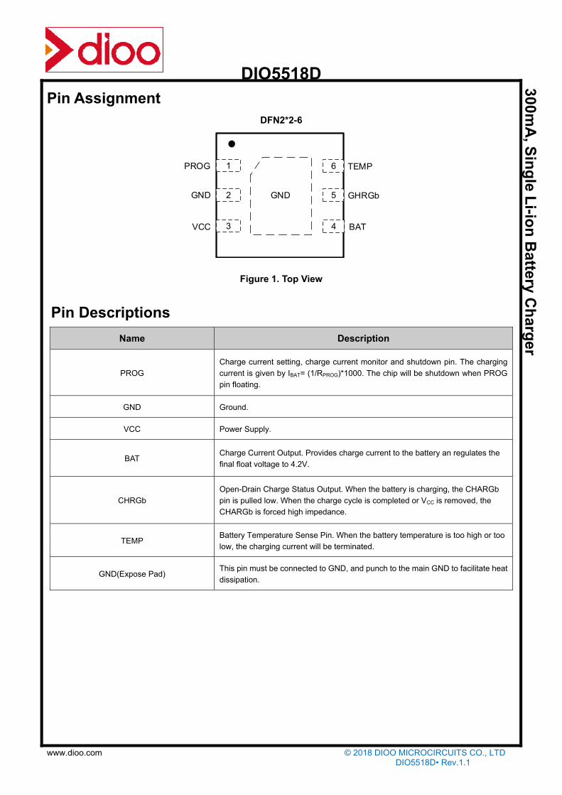
Pin Assignment
DFN2*2-6
GND2
3
6
5
4
GND
VCC
TEMP
GHRGb
BAT
1PROG
Figure 1. Top View
Pin Descriptions
Name Description
PROG
Charge current setting, charge current monitor and shutdown pin. The charging
current is given by IBAT= (1/RPROG)*1000. The chip will be shutdown when PROG
pin floating.
GND Ground.
VCC Power Supply.
BAT Charge Current Output. Provides charge current to the battery an regulates the
final float voltage to 4.2V.
CHRGb
Open-Drain Charge Status Output. When the battery is charging, the CHARGb
pin is pulled low. When the charge cycle is completed or VCC is removed, the
CHARGb is forced high impedance.
TEMP Battery Temperature Sense Pin. When the battery temperature is too high or too
low, the charging current will be terminated.
GND(Expose Pad) This pin must be connected to GND, and punch to the main GND to facilitate heat
dissipation.

DIO5518D
www.dioo.com © 2018 DIOO MICROCIRCUITS CO., LTD DIO5518D• Rev.1.1
300mA
, Sin
gle L
i-ion
Battery C
harg
er
Absolute Maximum Ratings
Stresses beyond those listed under “Absolute Maximum Rating” may cause permanent damage to the device. These are stress
ratings only and functional operation of the device at these or any other condition beyond those indicated in the operational
sections of the specifications is not implied. Exposure to absolute maxim rating conditions for extended periods may affect device
reliability.
Parameter Rating Unit
Supply Voltage -0.3~10 V
PROG Voltage -0.3~VCC V
BAT Voltage -0.3~10 V
CHRGb Voltage -0.3~VCC V
BAT Pin Current 300 mA
Thermal Resistance, Junction to Ambien RθJA 140 °C/W
Power Dissipation 0.6 W
Junction Temperature 150 °C
Operation Temperature -45~85 °C
Storage Temperature -65~125 °C
Lead Temperature (Soldering 10s) 260 °C
Recommend Operating Conditions The Recommended Operating Conditions table defines the conditions for actual device operation. Recommended Operating
conditions are specified to ensure optimal performance to the datasheet specifications. DIOO does not Recommend exceeding
them or designing to Absolute Maximum Ratings.
Parameter Rating Unit
Input Supply Voltage 4.5 to 5.5 V
Operating Temperature Range -40 to 85 °C

DIO5518D
www.dioo.com © 2018 DIOO MICROCIRCUITS CO., LTD DIO5518D• Rev.1.1
300mA
, Sin
gle L
i-ion
Battery C
harg
er
Electrical Characteristics VCC=5V, TA = 25°C (unless otherwise noted)
Symbol Parameter Conditions Min. Typ. Max. Unit
ISOLYCHRG Charge Mode Supply Current RPROG=10kΩ 250 2000 µA
RPROG=20kΩ 200 2000 µA
IBATCHRG Charge Mode Battery Current
RPROG=10kΩ 90 100 110 mA
RPROG=20kΩ 44 49 54 mA
RPROG=30kΩ 25 28.5 32 mA
VPROGCHRG PROG Pin Voltage RPROG=10kΩ 0.93 1.00 1.07 V
RPROG=20kΩ 0.93 1.00 1.07 V
ISPLYSTBY Standby Mode Supply Current Charge Terminated 136 500 µA
IBATSTBY Standby Mode Battery Current Charge Terminated 0 -2.5 -6 µA
ISPLYASD Shutdown Mode Supply Current VCC<VBAT 20 42 90 µA
IBATASD Shutdown Mode BAT Pin Current VCC<VBAT ±0.05 ±1 µA
ISPLYUVLO UVLO Mode Supply Current VCC<VUV 20 42 90 µA
IBATUVLO UVLO Mode BAT Pin Current VCC<VUV ±0.05 ±1 µA
ISPLYOVLO OVLO Mode Supply Current VCC>VOV 40 µA
IBATOVLO OVLO Mode BAT Pin Current VCC>VOV ±0.05 ±1 µA
ISPLYSHUT Shutdown Mode Supply Current RPROG not Connected 20 42 70 µA
IBATSHUT Shutdown Mode BAT Pin Current RPROG not Connected ±0.05 ±1 µA
IBATMSD Manual Shutdown BAT Pin Current VPROG=1.3V ±0.05 ±1 µA
IBATSLEEP Sleep Mode BAT Pin Current VCC=0V ±0.05 ±1 µA
ICharge_terminated 100mA/10mA charger terminated RPROG=10kΩ 10 µA
VCharge_terminated RPROG=10kΩ 0.1 V
VFLOAT Float Voltage 4.158 4.2 4.242 V
ITRIKL Trickle Charge Current RPROG=10kΩ 10 mA
VTRIKL Trickle Charge Voltage Threshold RPROG=10kΩ 2.8 2.9 3.0 V
VTRIKL, HYS Trickle Charge Voltage Hysteresis RPROG=10kΩ 100 mV
VUVLO UVLO Threshold From VCC Low to High 3.6 3.8 4.0 V
DIO5518D
www.dioo.com © 2018 DIOO MICROCIRCUITS CO., LTD DIO5518D• Rev.1.1
300mA
, Sin
gle L
i-ion
Battery C
harg
er
Electrical Characteristics (continued) VCC=5V, TA= 25°C (unless otherwise noted)
Symbol Parameter Conditions Min. Typ. Max. Unit
VUVLO, HYS UVLO Hysteresis 250 mV
VOVLO OVLO Threshold From VCC Low to High 6 V
VOVP_Hys OVLO Hysteresis 180 mV
VMSD Manual Shutdown Threshold Voltage PROG Pin Rising
PROG Pin Falling
1.2
1.0
1.3
V
V
VASD Vcc-VBAT Lockout Threshold Voltage VCC from low to High
VCC from High to Low
5
120
50
mV
mV
ΔVRECHRG Auto Recharge Battery Voltage 100 150 200 mV
VCHRGb CHRGb Pin Output Low Voltage ICHRGb=5mA 0.3 0.6 V
TLIM Junction Temperature In CT Mode 165 °C
RON Power FET ON Resistance 250 mΩ
TSS Soft-Start Time RPROG=2kΩ 50 µs
TRECHRG Recharge Comparator Filter Time 2 ms
TTERM Termination Comparator Filter Time 1 ms
IPROG PROG Pin Pull-up Current 0.35 0.5 0.75 µA
VTEMP_EN Battery Temperature Detect Function
Threshold Volatge TEMP Pin Rising
TEMP Pin Falling
0.18
0.29
0.2 0.32
V
V
VTEMP_H TEMP Pin High Threshold Voltage TEMP Pin Rising
TEMP Pin Falling
72
80
73.5
82
%VCC
%VCC
VTEMP_L TEMP Pin Low Threshold Voltage TEMP Pin Rising
TEMP Pin Falling
43
48.5
45
50
%VCC
%VCC
Specifications subject to change without notice.
DIO5518D
www.dioo.com © 2018 DIOO MICROCIRCUITS CO., LTD DIO5518D• Rev.1.1
300mA
, Sin
gle L
i-ion
Battery C
harg
er
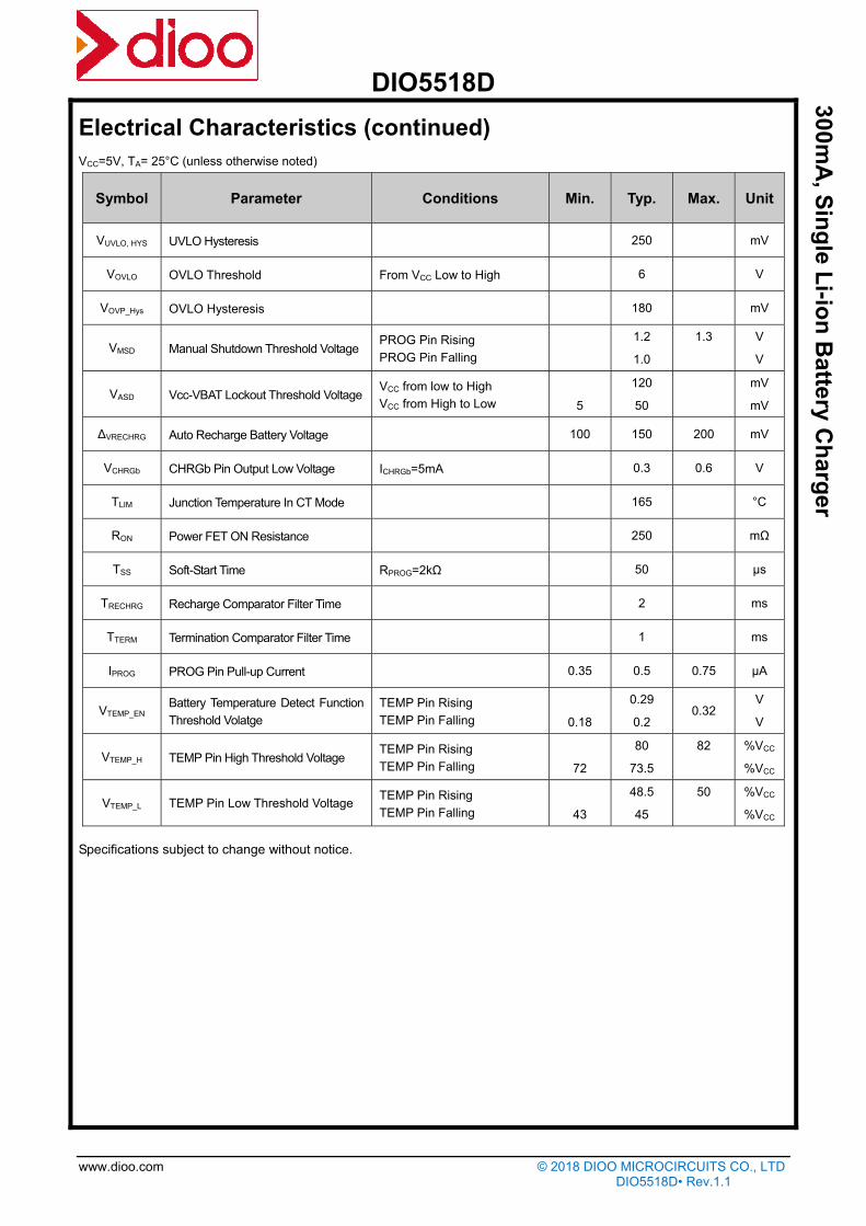
Typical Performance Characteristics
VCC=5V, TA= 25°C (unless otherwise noted)
PROG Pin Voltage vs. Ambient Temperature Float Voltage vs. Ambient Temperature
Icharge vs. Ambient Temperature I trickle charge vs. Ambient Temperature
VCC Start-up VCC Shut-down
(VCC=5V, RPROG=10kΩ,CBAT=10μF,BAT connect to battery) (VCC=5V, RPROG=10kΩ,CBAT=10μF,BAT connect to battery)

DIO5518D
www.dioo.com © 2018 DIOO MICROCIRCUITS CO., LTD DIO5518D• Rev.1.1
300mA
, Sin
gle L
i-ion
Battery C
harg
er
Charging Curve VBAT
(VCC=5V, RPROG=10kΩ,CBAT=10μF) (VCC=5V, RPROG=10kΩ,CBAT=10μF)
Block Diagram
VCC
1000X
BAT
TEMP
CA
HDNb
R3
R4
CHRGb R5
PROG
GND
165 C
TDIE
80%Vcc
TA1X
5uA
C4 MA R1
VAR2
45%VccC5
S C1
1V
0.3V
C2
To1uA
VccBAT C32.9V
REF1.2V
0.1V
0.5μA
Figure 2. Function Block Diagram

DIO5518D
www.dioo.com © 2018 DIOO MICROCIRCUITS CO., LTD DIO5518D• Rev.1.1
300mA
, Sin
gle L
i-ion
Battery C
harg
er
Operation information The DIO5518D is a single cell Lithium-Ion battery charger using a constant-current / constant-voltage algorithm.
It can deliver up to 100mA of charge current with a final float voltage accuracy of ±1%. The DIO5518D
includes an internal P-channel power MOSFET and thermal regulation circuitry. No blocking diode or external
current sense resistor is required; thus, the basic charger circuit requires only two external components.
Furthermore, the DIO5518D is capable of operating from a USB power source.
Normal charge cycle
A charge cycle begins when the voltage at the VCC pin rises above the UVLO threshold level and a 1% program
resistor is connected from the PROG pin to ground or when a battery is connected to the charger output. If the
BAT pin is less than 2.9V, the charger enters trickle charge mode. In this mode, the DIO5518D supplies
approximately 1/10 the programmed charge current to bring the battery voltage up to a safe level for full current
charging.
When the BAT pin voltage rises above 2.9V, the charger enters constant-current mode, where the
programmed charge current is supplied to the battery. When the BAT pin approaches the final float voltage, the
DIO5518D enters constant-voltage mode and the charge current begins to decrease. The charge cycle ends
when the PROG voltage is less than 100mV.
Programming charge current
The charge current is programmed using a single resistor from the PROG pin to ground. The battery charge
current of constant current mode is 1000 times the current out of the PROG pin. The program resistor and the
charge current of constant current are calculated using the following equations:
10001
PROGCHRG
R
VI
Charge termination
A charge cycle is terminated when the charge current falls to 1/10 of the programmed value after the final float
voltage is reached. This condition is detected by using an internal, filtered comparator to monitor the PROG pin.
When the PROG pin voltage falls below 100mV for longer than TTERM (typically 1ms), charging is terminated.
The charge current is latched off and the DIO5518D enters standby mode, where the input supply current
drops to 136µA. (Note: CC/10 termination is disabled in trickle charging mode and thermal limiting modes).
When charging, transient loads on the BAT pin can cause the PROG pin to fall below 100mV for short periods
of time before the DC charge current has dropped to 1/10 of the programmed value. The 1ms filter time (TTERM)
on the termination comparator ensures that transient loads of this nature do not result in premature charge
cycle termination. Once the average charge current drops below 1/10 of the programmed value, the DIO5518D
terminates the charge cycle and ceases to provide any current through the BAT pin, the chip will be put into
standby mode. In this state, all loads on the BAT pin must be supplied by the battery.

DIO5518D
www.dioo.com © 2018 DIOO MICROCIRCUITS CO., LTD DIO5518D• Rev.1.1
300mA
, Sin
gle L
i-ion
Battery C
harg
er
Figure 3. State Diagram of a Typical Charge Cycle
The DIO5518D constantly monitors the BAT pin voltage in standby mode. If this voltage drops below the 4.05V
recharge threshold (VRECHRG), another charge cycle begins and current is once again supplied to the battery.
The state diagram of a typical charge cycle is as Figure 3.
Charge status indicator
DIO5518D has an open-drain status indicator output CHRGb. CHRGb is pull-down when the DIO5518D in a
charge cycle. In other status CHRGb is in high impedance. CHRGb is in high impedance when the battery out
of the normal temperature.
Represent in failure state, when TEMP pin in typical connecting, and the charger with no battery: red LED don’t
light. The battery temperature sense function is disabled by connecting TEMP pin to GND. If battery is not
connected to charger and the BAT pin connects a 10µF capacitor, the frequency of CHRGb flickers is about
1-4s.
Charger state Red
GHRGb
Charging light
Battery in full state dark
UVLO, Battery temperature is outside TEMP range,
battery is note connected (Use TEMP) dark
BAT pin is connected to 10µF and no battery mode (TEMP=GND) Red LED flicker and the
frequency is 1~4s

DIO5518D
www.dioo.com © 2018 DIOO MICROCIRCUITS CO., LTD DIO5518D• Rev.1.1
300mA
, Sin
gle L
i-ion
Battery C
harg
er
Thermal Limiting
An internal thermal feedback loop reduces the programmed charge current if the die temperature attempts to
rise above a preset value of approximately 165°C. This feature protects the DIO5518D from excessive
temperature and allows the user to push the limits of the power handling capability of a given circuit board
without risk of damaging the DIO5518D. The charge current can be set according to typical (not worst-case)
ambient temperature with the assurance that the charger will automatically reduce the current in worst-case
conditions.
Battery Temperature Sensing
To prevent the damage caused by the very high or very low temperature done to the battery pack, the
DIO5518D continuously senses the battery pack temperature by measuring the voltage at TEMP pin
determined by the voltage divider circuit and the battery’s internal NTC thermistor.
The DIO5518D compares the voltage at TEMP pin (VTEMP) against its internal VLOW and VHIGH thresholds to
determine if charging is allowed. In DIO5518D, VLOW is fixed at 45%×VCC, while VHIGH is fixed at 80%×VCC. If
VTEMP<VLOW or VTEMP>VHIGH, it indicates that the battery temperature is too high or too low and the charge cycle
is suspended. When the VTEMP is between VLOW and VHIGH, charging cycle resumes. The battery temperature
sensing function can be disabled by connecting the TEMP pin to GND.
Selecting R1 and R2
The values of R1 and R2 in the application circuit (Figure1) can be determined according to the assumed
temperature monitor range and thermistor’s values. The Follows is an example: Assume temperature monitor
range is TL~TH, (TL<TH); the thermistor in battery has negative temperature coefficient (NTC), RTL is
thermistor’s resistance at TL,RTH is the resistance at TH,so RTL>RTH,then
At temperature TL, the volatge at TEMP pin is:
CCTL
TLTEMPL V
RRR
RRV
//
//
21
2
At temperature TH, the volatge at TEMP pin is:
CCTH
THTEMPH V
RRR
RRV
//
//
21
2
Because )8.0( 22 KVKVV CCHIGHTEMPL
)45.0( 11 KVKVV CCLOWTEMPH
Then we can have:
21
121
)(
)(
KKRR
KKRRR
THTL
THTL
)()(
)(
212211
122
KKKRKKKR
KKRRR
THTL
THTL
Likewise, for positive temperature coefficient thermistor in battery, we have RTH>RTL and we can calculate:
21
121
)(
)(
KKRR
KKRRR
TLTH
TLTH

DIO5518D
www.dioo.com © 2018 DIOO MICROCIRCUITS CO., LTD DIO5518D• Rev.1.1
300mA
, Sin
gle L
i-ion
Battery C
harg
er
)()(
)(
212211
122
KKKRKKKR
KKRRR
TLTH
TLTH
We can conclude that temperature monitor range is independent of power supply voltage VCC and it only
depends on R1, R2, RTL and RTH: The values of RTH and RTL can be found in ralated battery handbook or
deduced from testing data. In actual application, if only one terminal temperature is concerned (normally
protecting overheating), there is no ennd to use R2 but R1. It becomes very simple to calculate R1 in this case.
Undervoltage Lockout (UVLO)
An internal undervoltage lockout circuit monitors the input voltage and keeps the charger in shutdown mode
until VCC rises above the undervoltage lockout threshold. The UVLO circuit has a built-in hysteresis of 250mV.
Furthermore, to protect against reverse current in the power MOSFET, the UVLO circuit keeps the charger in
shutdown mode if VCC falls to within 50mV of the battery voltage. If the UVLO comparator is tripped, the
charger will not come out of shutdown mode until VCC rises 120mV above the battery voltage.
Overvoltage Lockout (OVLO)
An internal overvoltage lockout circuit monitors the input voltage and keeps the charger in shutdown mode until
VCC rises above the overvoltage lockout threshold. The OVLO circuit has a built-in hysteresis of 180mV.
Furthermore, to protect against reverse current in the power MOSFET, the OVLO circuit keeps the charger in
shutdown mode if VCC falls to within 50mV of the battery voltage. If the OVLO comparator is tripped, the
charger will not come out of shutdown mode until VCC rises 120mV above the battery voltage.
Manual Shutdown
At any point in the charge cycle, the DIO5518D can be put into shutdown mode by removing RPROG thus
floating the PROG pin. This reduces the battery drain current to less than 1µA and the supply current to less
than 50µA. A new charge cycle can be initiated by reconnecting the program resistor.
In manual shutdown, The CHRGb pin is in a high impedance state if the DIO5518D is in manual shutdown
mode or in the undervoltage lockout mode: either VCC is within 120mV of the BAT pin voltage or insufficient
voltage is applied to the VCC pin.
VCC 3TEMP
BAT
10µ
VCC
CHRGb
PROG
GND
6
F
R1 4 Li-Lon
10µF
1BATup
5
R PROG
2
Figure 4. Manual Shutdown Mode Application Circuit

DIO5518D
www.dioo.com © 2018 DIOO MICROCIRCUITS CO., LTD DIO5518D• Rev.1.1
300mA
, Sin
gle L
i-ion
Battery C
harg
er
Automatic recharge
Once the charge cycle is terminated, the DIO5518D continuously monitors the voltage on the BAT pin using a
comparator with a 2ms filter time (TRECHRG). A charge cycle restarts when the battery voltage falls below 4.05V
(Typ.) (which corresponds to approximately 80% to 90% battery capacity). This ensures that the battery is kept
at or near a fully charged condition and eliminates the need for periodic charge cycle initiations. CHRGb output
enters a pull-down state during recharge cycles.
Application Information
Typical Application
Figure 5. Typical applications W/T LED indicate
Figure 6. Typical applications W/T microprocessor detect

DIO5518D
www.dioo.com © 2018 DIOO MICROCIRCUITS CO., LTD DIO5518D• Rev.1.1
300mA
, Sin
gle L
i-ion
Battery C
harg
er
Stability considerations
The constant-voltage mode feedback loop is stable without an output capacitor provided a battery is connected
to the charger output. With no battery present, an output capacitor is recommended to reduce ripple voltage.
When using high value, low ESR ceramic capacitors, it is recommended to add a 1Ω resistor in series with the
capacitor. No series resistor is needed if tantalum capacitors are used.
In constant-current mode, the PROG pin is in the feedback loop, not the battery. The constant-current mode
stability is affected by the impedance at the PROG pin. With no additional capacitance on the PROG pin, the
charger is stable with program resistor values as high as 50KΩ. However, additional capacitance on this node
reduces the maximum allowed program resistor thus it should be avoided.
Thermal Limit
An internal thermal feedback loop reduces the programmed charge current if the die temperature attempts to
rise above a preset value of approximately 165°C. This feature protects the DIO5518D from excessive
temperature and allows the user to push the limits of the power handling capability of a given circuit board
without risk of damaging the DIO5518D. The charge current can be set according to typical (not worst-case)
ambient temperature with the assurance that the charger will automatically reduce the current in worst-case
conditions.
Power dissipation
The conditions that cause the DIO5518D to reduce charge current through thermal feed-back can be
approximated by considering the power dissipated in the IC. Nearly all of this power dissipation is generated
by the internal MOSFET. This is calculated to be approximately:
BATBATCCD IVVP )(
It is important to remember that DIO5518D applications do not be designed for worst-case thermal conditions
since the IC will automatically reduce power dissipation when the junction temperature reaches
approximately 165°C (Constant temperature mode).
VCC bypass capacitor
Many types of capacitors can be used for input bypass, however, caution must be exercised when using
multilayer ceramic capacitors. Because of the self-resonant and high Q characteristics of some types of
ceramic capacitors, a 10µF ceramic capacitor is recommended for this bypass capacitor. Due to a high voltage
transient will be generated under some start-up conditions, such as connecting the charger input to a live
power source.
Charge current soft-start
The DIO5518D includes a soft-start circuit to minimize the inrush current at the start of a charge cycle. When a
charge cycle is initiated, the charge current ramps from zero to the full-scale current over a period of
approximately 100µs. This has the effect of minimizing the transient current load on the power supply during
start-up.

DIO5518D
www.dioo.com © 2018 DIOO MICROCIRCUITS CO., LTD DIO5518D• Rev.1.1
300mA
, Sin
gle L
i-ion
Battery C
harg
er
CONTACT US Dioo is a professional design and sales corporation for high-quality and performance analog semiconductors. The company focuses
on industry markets, such as, cell phone, handheld products, laptop, and medical equipment and so on. Dioo’s product families include
analog signal processing and amplifying, LED drivers and charger IC. Go to http://www.dioo.com for a complete list of Dioo product
families.
For additional product information, or full datasheet, please contact with our Sales Department or Representatives.