diploma mechanical v thermal engineering u 5-reaction turbine
TRANSCRIPT

REACTION TURBINE
Course: DIPLOMA MECHANICAL ENGINEERINGSubject: THERMAL ENGINEERING
Unit: 5

2
Reaction Turbine
In this type of turbine, there is a gradual pressure drop and takes place continuously over the fixed and moving blades. The rotation of the shaft and drum, which carrying the blades is the result of both impulse and reactive force in the steam. The reaction turbine consist of a row of stationary blades and the following row of moving blades

3
The fixed blades act as a nozzle which are attached inside the cylinder and the moving blades are fixed with the rotor as shown in figure
When the steam expands over the blades there is gradual increase in volume and decrease in pressure. But the velocity decrease in the moving blades and increases in fixed blades with change of direction.

4
Because of the pressure drops in each stage, the number of stages required in a reaction turbine is much greater than in a impulse turbine of same capacity.
It also concluded that as the volume of steam increases at lower pressures therefore the diameter of the turbine must increase after each group of blade rings.

REACTION TURBINE PRINCIPLE
1

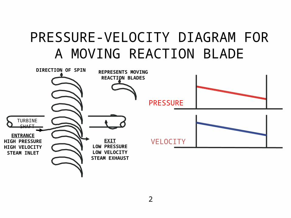
PRESSURE-VELOCITY DIAGRAM FORA MOVING REACTION BLADE
TURBINESHAFT
DIRECTION OF SPIN
ENTRANCEHIGH PRESSUREHIGH VELOCITYSTEAM INLET
REPRESENTS MOVINGREACTION BLADES
EXITLOW PRESSURELOW VELOCITY
STEAM EXHAUST
PRESSURE
VELOCITY
2
.Compounding in Steam Turbine.
The compounding is the way of reducing the wheel or rotor speed of the turbine to optimum value. It may be defined as the process of arranging the expansion of steam or the utilization of kinetic energy or both in several rings.

There are several methods of reducing the speed of rotor to lower value. All these methods utilize a multiple system of rotors in series keyed on a common shaft, and the seam pressure or jet velocity is absorbed in stages as the steam flower over the blades.

Different methods of compounding are: 1.Velocity Compounding 2.Pressure Compounding 3.Pressure Velocity Compounding.
These are explained in detail as given below:

VELOCITY COMPOUNDED TURBINE
3

PRESSURE COMPOUNDED TURBINE
4

13
1.http://www.middleton.ednet.ns.ca/mrhs%20web/pages/cox/grade%2011/assignments/reading%20assignments/Assignment%201/reaction%20turbine%20dia.JPG
2. http://image.slidesharecdn.com/steamturbine-141022022635-conversion-gate01/95/steam-turbine-impulse-and-reaction-turbine-working-principlecompounding-of-steam-turbines-19-638.jpg?cb=1416374049 3.http://nptel.ac.in/courses/112104117/chapter_6/10.gif
4.http://upload.wikimedia.org/wikipedia/commons/thumb/8/87/Fig3-Subik_Kumar-Schematic_Diagram_of_Pressure_compounded_Impulse_Turbine_(corrected).jpg/400px-Fig3-Subik_Kumar-Schematic_Diagram_of_Pressure_compounded_Impulse_Turbine_(corrected).jpg
CONTENT REFERENCES
1. Thermal Engineering-R.S Khurmi/J.K Gupta/S.Chand.2. Thermal Engineering-P.L.Bellaney/ Khanna publishers.

THANK YOU