directions — expert version exterior hubble space...
TRANSCRIPT

www.hubblesite.org/go/model
Materials:
The patterns and instructions, which can be •downloaded at www.hubblesite.org/go/model. The pattern pieces should be printed onto 32-lb paper. (You may want to have extra printouts handy in case you need them.)
Cardboard (the weight of a cereal box is good)•
Glues: White or clear craft glue, gluestick (per-•manent), and superglue
Good scissors•
A sharp craft knife with extra blades•
A metal straightedge and/or ruler•
A cutting board or similar surface•
Optional (but very helpful) materials:
Tweezers for handling small pieces•
A small paintbrush for applying glue•
Flat-edged toothpicks for applying glue and •superglue
Thin dowels and/or tapestry needles to help roll •up thin tubes
Clear spray-on sealant to protect the finished •model
Construction tips:
• Readthroughallthedirectionsfirstandmakesureyou know where all of your materials are and what you will need to do.
• Alwaysfollowsafetyprecautionswhenusingasharpblade, like the one on a craft knife.
•Haveextrabladesavailableandsafelystoreduntilyou need them. Change the blade whenever it starts to become dull; a sharp blade cuts more easily and is safer to use. Dispose of used blades safely.
•Don’tcutoutpiecesuntilyouneedthem,soyoucankeep track of them. You can also lightly pencil the piece numbers on the backs. Pieces are numbered and labeled in the recommended order of assembly.
• Scorefoldlinesbeforecuttingoutthepieces.Thiswill make it much easier to fold the flaps later. Draw the edge of a narrow but not sharp object — like a butter knife or a small flathead screwdriver — along the dotted lines to make an indentation. Use a ruler to make sure your lines are straight. Alternately, you can use the “dull” side of a craft knife, with averylightpressuresoyoudon’tcutthroughthepaper. Fold lines that are on cardboard require heavy scoring: use the point of the scissors or a craft knife to lightly cut along the line, just enough to make a small groove, but not going more than halfway through the cardboard.
• Foldthepiecesandtrytofitthemtogetheratleastonce before applying the glue.
•Verysmallfoldsareeasiertomakewithapairoftweezers.
• Keepyourhandsandyourworkplacecleanandclearof scraps to prevent accidents and errors.
•Protectyourworksurfacewithscrappaper,especially when gluing.
• Keepyourhandsclean,soyouwon’tgetglueorfingerprints on your model.
Hubble Space Telescope Paper Model
Directions — Expert version exterior
Hubble Space TelescopeExpert Model — ExteriorDirectionsDownloads, patterns, and other information at: www.hubblesite.org/go/model
Before beginning construction:
1.Readallinstructionscarefully!
2.Haveallofyourmaterialsready.
3. Make sure a responsible adult is nearby to help out if necessary.
4. Glue all the pages that require it onto card-board and paper ahead of time, so they can dry. If they curl up when drying, press them under heavy books.

www.hubblesite.org/go/model
Hubble Space Telescope Advanced Paper Model Instructions — Exterior
•Whenusingwhiteglue,applyinathincoatwithaflat toothpick or a small paintbrush. If you wait a few seconds for it to become “tacky” it will stick more easily.
•Whenusingsuperglue,followallthesafetyprecautionsonthelabel.BeVERYcarefulnottogetany on your hands or skin, and do not touch pieces that have had superglue applied for several minutes, to be sure it is dry.
•Onlyuseasmuchglueasisneededtocoverthesurfacesyou’reconnectingwithathinlayer.Toomuch glue may end up on your hands or on the surface of your model.
• Becarefulusingsharpscissorsandblades.Havea responsible adult nearby to help you if you need assistance.
•Whengluingtwoflatpiecesofpapertogether,useas little glue as possible. The glue stick is very helpful for this.
• Unlessotherwiseindicated,allowthegluetodrybefore going on to the next step.
• Takeyourtimeandbepatient!
Ton Noteboom describes himself as a “space age kid.” Growing up in the Netherlands, he followed the progress ofthespaceprogram,hearingaboutSputnikontheradio,and watching Neil Armstrong take his first steps on the Moon. But what really fascinated him was the technol-ogy – the technology that got the astronauts to the Moon, the technology that brought the journey back to people around the world.
“The force of the rockets, the hardware part – that was what interested me,” he said. “It was amazing to see pic-tures on the television screen, especially in that time, that came all the way from the Moon.”
Hegothisfirstcardboardmodelofaboatwhenhewas11yearsold,asapresentfromSinterklaas,theDutchversionofSantaClaus.Themodeljoinedhisalreadyextensivecollection of plastic models, but after a short time that phase gave way to a period of model-train building that he shared with his father. And that was it until the day about five years ago, surfing the Web, that he started find-ing plans for elaborate paper models online.
Lured by nostalgia, and with both training in silversmith-ing and job experience in construction engineering under hisbelt,Noteboomthoughthe’dgivethepapermodelsanothershot.“Isaid,‘Well,let’stryit,’anditstuck,”hesaid.Whenhecouldn’tfindamodeloftheSaturnVrocket,hedecidedtodesignhisown.“Ididn’tstartwithan easy one,” he noted wryly. “You just put your teeth together and go. It took a lot of patience, paper , ink and time.It’sfascinatingtoseeamodeltakingshape.”
Hisloveoftechnologyandengineeringisevidentinboth the level of detail and the painstaking attention to structure and precise construction in the 35 paper models
Noteboom has designed and shared online with the world.Oneofthegreatestcomplimentshe’sreceived,hesays, is from a model builder that praised the way every-thing about his models “fit together.”
The allure lies in constructing something three-dimen-sionaloutofaflatpieceofpaper,Noteboomsaid.“It’sintriguing to make something very sturdy out of some-thingthatisn’t.Itreatthepieceofpaperasapieceofmetal, though metal is easier because you can shape it intointricateforms.Withpaperyoucan’t.”
In addition to designing paper models, Noteboom is a licensed radio amateur hobbyist specializing in television transmissions.HelivesinthesmallvillageofRozenburg,nearRotterdam,withthreecats,andhandlesfacilityoperations at a local school.
MoreofTon’smodelscanbefoundat http://jleslie48.com
About Hubble Space Telescope
Thishighly-detailedmodeloftheHubbleSpaceTele-scope(HST)isintendedforexperiencedmodel-builders.You may build only the exterior part of the model which showsalloftheHST’ssurfacefeatures,oryouhavetheoption of also making the removable internal structure which includes the mirrors and instruments. All of the files you need can be downloaded from www.hubblesite.org/go/model
Thedetailsofthismodelarebasedonthetelescope’sconfigurationafterServicingMission3Bin2002.
Construction tips continued:
About the designer

Hubble Space Telescope Expert Model — Exterior Directions Page 1
www.hubblesite.org/go/model
Assembly instructions
Aft shroud
1. Glue tabs 3 and 4 to the back of piece 1 along the opposing shorter sides (fig. 1).
2. Then glue the free ends of the tabs behind piece 2 so that it forms a short tube, making sure that the row of bays on pieces 1 and 2 line up together, forming a ring around the top of the tube. Be sure the edges of the pieces 1 and 2 meet very tightly (fig. 2). This is the aft shroud: the three black circles are on the front side and the row of bays goes around the top.
3. Aft shroud supports: First, turn the aft shroud upside-down and test-fit ring 5 into the bottom. It should fit snugly just inside the edge of the tube. Apply a small amount of glue all the way around the outside edge of the ring. Carefully insert the ring just inside the bottom edge of the tube and make sure the paper edges are securely glued all the way around. Let it dry (fig. 3).
4. Rollstrip6intoaloopandinsertitinsidetheaftshroudsoitis up against the glued ring (fig. 4). Use very little glue to glue down the ends if necessary.
5. Insert ring 7 into the tube so that it snug against the edge of the spacer strips. Alternate spacers and rings until you get to ring 15 (fig. 5).
6. Glue ring 15 just inside the top edge of the aft shroud, just as you did with the first ring, by applying a little glue around theoutsideedge(fig.6).
7. Baydoors:Thesheetwiththeinstrumentcovers(16-19)andthebaydoors(20-29)shouldbefoldedinhalfandgluedtogether for extra thickness before you cut out the pieces. TIP: a glue stick works very well for this (fig. 7).
8. Cut them out and apply the covers and doors where indicated on the aft shroud (fig. 8). If you gently bend them into a curved shape to match the aft shroud cylinder before glueing, they will be much easier to apply.
fig. 1
fig. 3
fig. 5
fig. 2
a.
b.
fig. 4a.
b.
a.b.
fig. 6
fig. 7
fig. 8

Hubble Space Telescope Expert Model — Exterior Directions Page 2
www.hubblesite.org/go/model
9. Gentlybendpiece30intoacurvedshapeandglueintoplaceonpiece28(bay10)(fig.9).
10. Carefully fold pieces 31 and 32 and glue themintoshapeasshallowboxes(fig.10a-c). When dry, glue the boxes into position on pieces 21 and 22 (bays 2 and 3) (fig. 10d).
11.NICMOScryocooler:Gluepieces34and35whereindicatedontopiece33,theNICMOScryocooler(fig.11a).Scorethetabonthecryocoolerdeeplyandbendinwardata90°angle(fig.11b).Using this tab at the top end, and the back of the cryocooler at the bottom, glue onto the aft shroud cylinder
where indicated. It will stick out at a slight angle from the aft shroud (fig. 11c)
12.Aftscuffplates:Assemblepieces36and37asshowntomakethe scuff plates, gluing the tabs underneath the thin curved strip. Make sure that the ends of the thin strip line up with the edges of the outer glue tabs (fig. 12).
13.Foldpieces36aand37aintosmallboxesasshown,withthetopflapsopenedout.[NOTE:Withsmallboxeslikethese,itis extra important to score carefully before cutting the pieces out. Use tweezers to bend the flaps, and to help flatten them down when gluing.] Glue the finished boxes open-side-down to the underside of the scuff plates (fig. 13).
14.Rollthestrips38and39astightlyaspossibleandgluetheends down so you have a very small cylinder; it may be easier to roll them around a piece of thick wire or a tapestry needle if you have such items (fig. 14).
15. Glue these small cylinders on top of the scuff plates at the cross mark. Glue the assembled scuff plates where indicated on the aft shroud body, so that the flat side of the plate faces the “front” of the aft shroud, where the three circles are (fig. 15).
fig. 9 fig. 10
a.fig. 11
d.
b.
c.view from front view from side
view from bottom view from top
fig. 12
fig. 13
fig. 14fig. 15
Hubble Space Telescope Expert Model — Exterior Directions Page 3
www.hubblesite.org/go/model
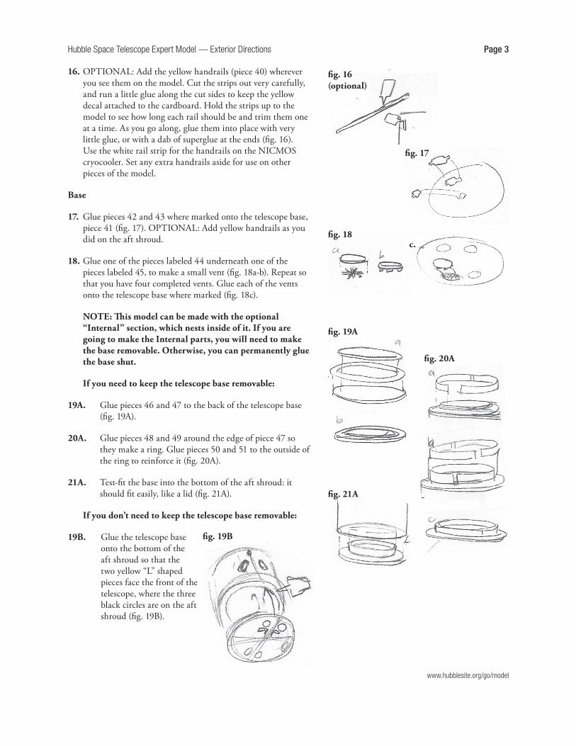
16.OPTIONAL:Addtheyellowhandrails(piece40)whereveryou see them on the model. Cut the strips out very carefully, and run a little glue along the cut sides to keep the yellow decalattachedtothecardboard.Holdthestripsuptothemodel to see how long each rail should be and trim them one at a time. As you go along, glue them into place with very littleglue,orwithadabofsuperglueattheends(fig.16).UsethewhiterailstripforthehandrailsontheNICMOScryocooler.Setanyextrahandrailsasideforuseonotherpieces of the model.
Base
17. Glue pieces 42 and 43 where marked onto the telescope base, piece41(fig.17).OPTIONAL:Addyellowhandrailsasyoudid on the aft shroud.
18. Glue one of the pieces labeled 44 underneath one of the pieceslabeled45,tomakeasmallvent(fig.18a-b).Repeatsothat you have four completed vents. Glue each of the vents onto the telescope base where marked (fig. 18c).
NOTE: This model can be made with the optional “Internal” section, which nests inside of it. If you are going to make the Internal parts, you will need to make the base removable. Otherwise, you can permanently glue the base shut.
If you need to keep the telescope base removable:
19A. Gluepieces46and47tothebackofthetelescopebase(fig.19A).
20A. Gluepieces48and49aroundtheedgeofpiece47sotheymakearing.Gluepieces50and51totheoutsideoftheringtoreinforceit(fig.20A).
21A. Test-fit the base into the bottom of the aft shroud: it should fit easily, like a lid (fig. 21A).
If you don’t need to keep the telescope base removable:
19B. Glue the telescope base onto the bottom of the aft shroud so that the two yellow “L” shaped pieces face the front of the telescope, where the three black circles are on the aft shroud(fig.19B).
fig. 16 (optional)
c.fig. 18
fig. 17
fig. 19B
fig. 19A
fig. 20A
fig. 21A
Hubble Space Telescope Expert Model — Exterior Directions Page 4
www.hubblesite.org/go/model
Forward shroud
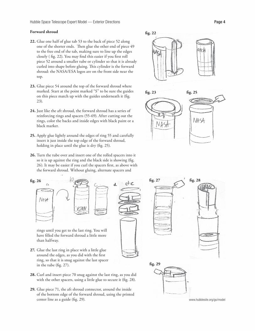
22. Glue one half of glue tab 53 to the back of piece 52 along oneoftheshorterends.Thengluetheotherendofpiece49to the free end of the tab, making sure to line up the edges closely ( fig. 22). You may find this easier if you first roll piece 52 around a smaller tube or cylinder so that it is already curled into shape before gluing. This cylinder is the forward shroud:theNASA/ESAlogosareonthefrontsidenearthetop.
23. Glue piece 54 around the top of the forward shroud where marked.Startatthepointmarked“S”tobesuretheguideson this piece match up with the guides underneath it (fig. 23).
24. Just like the aft shroud, the forward shroud has a series of reinforcingringsandspacers(55-69).Aftercuttingouttherings, color the backs and inside edges with black paint or a black marker.
25. Apply glue lightly around the edges of ring 55 and carefully insert it just inside the top edge of the forward shroud, holding in place until the glue is dry (fig. 25).
26. Turn the tube over and insert one of the rolled spacers into it so it is up against the ring and the black side is showing (fig. 26).Itmaybeeasierifyoucurlthespacersfirst,asabovewiththe forward shroud. Without gluing, alternate spacers and
rings until you get to the last ring. You will have filled the forward shroud a little more than halfway.
27. Glue the last ring in place with a little glue around the edges, as you did with the first ring, so that it is snug against the last spacer in the tube (fig. 27).
28.Curlandinsertpiece70snugagainstthelastring,asyoudidwith the other spacers, using a little glue to secure it (fig. 28).
29. Glue piece 71, the aft shroud connector, around the inside of the bottom edge of the forward shroud, using the printed centerlineasaguide(fig.29).
fig. 22
fig. 23 fig. 25
fig. 26d.
fig. 27 fig. 28
fig. 29

Hubble Space Telescope Expert Model — Exterior Directions Page 5
www.hubblesite.org/go/model
30.Gluepieces72and73together,back-to-back(fig.30).
31.OPTIONAL:ifyouareusingtheyellowhandrailsonotherparts of the model, carefully cut and seal rails 74 as you did with the previous set in step 16.Withadropofgluehereandthere, carefully bend the rails to glue them into the curved shapes printedonpiece73(fig.30).Therewill be a few extra pieces for the topsoftheOTAbayslaterwhichwill need to be applied the same way.
32.Slidepiece73overtheaftshroudconnectorlikeacollar,with the bay placement guides facing up. Glue into place at the base of the forward shroud, being careful to align the red arrows/bay placement guides on both pieces (fig. 32).
33.AssembletheOTAbays,pieces75-83(fig.33).
34. Glue the bays where marked onto the forward shroud and to each other (fig. 34).
35.Gluepieces84-86wheremarkedontopofthebays(fig.35).OPTIONAL:Addtheyellowhandrailstothesethreepieces,as described in step 31.
36.OPTIONAL:Ifyouwanttoaddthebaydoorsforextradimension, as with the larger bay doors on the aft shroud, gluepieces75x-83xontothefacesoftheOTAbays.Becareful to line up the hinge markings around the edges (fig. 39).
37. Gluepieces87-95wheremarkedontheforwardshroud.Itmaybeeasierifyougentlybendpiece95intothepropershape before gluing (fig. 37).
38.Gluepiece96intoplaceontheforwardshroud,bendingslightlybeforegluing.Gluepiece97tocontinue96;itwillarchslightlywhengoingoverthetopofpiece95(fig.38).
fig. 30
fig. 31
fig. 32
fig. 33
fig. 34
fig. 35
fig. 36 (optional)
fig. 37
fig. 38
piece 75
other OTA bays

Hubble Space Telescope Expert Model — Exterior Directions Page 6
www.hubblesite.org/go/model
39.OPTIONAL:ifyouareusingtheyellowhandrails,applythem now to the forward shroud as you did on the aft shroud instep16.
40.Assemblepieces99-101,thehigh-gainantennaclamps(HGAclamps)(fig.40).[NOTE:Withsmallboxeslikethese,itisextra important to score carefully before cutting the piece out. Use tweezers to bend the flaps, and to help flatten the flaps down when gluing.]
41.GluetheassembledHGAclampswheremarkedontheforward shroud, so that the curved side is facing the top of the tube (fig. 41).
42.Assemblethesolararrayclamp102,whichisverysimilartotheHGAclampsabove.Gluepiece103toitwhereindicated(fig.42).Assemblepieces104-105thesameway.
43. Glue completed solar array clamps to the forward shroud where marked, so that the curved side is facing the top of the tube and the yellow brackets face the bottom (fig. 43).
44. To make the base for the solar panel connector, fold piece 106intoashallowboxandgluepiece107insideforsupport.Applyalittlegluearoundtheedgesofpiece107sotheflapson the box will stick (fig. 44).
45. Glue the solar panel base onto the forward shroud where marked, so that the circle is closer to the top of the model (fig. 45).
46.Repeatthelasttwostepswithpieces108-109tomaketheconnectoron the other side. This is where the solar arrays will attach.
47. Assemblepieces110and111(fig.47).
48.GluewheremarkednexttotheOTAbays(fig.48).
49.TomakethebasesfortheHGAhinge,firstfoldpieces113and 115 in half along the dotted line and glue them together to make them double-thick. Assemble pieces 112-115 the same way you made the solar array connector base in step 44.
50.Deeplyscorepiece116onthereversesideandbendforwardatapproximatelya45°angle.Gluepiece117behindpiece116(fig.50).Repeatwithpieces118-123tomakefouridenticalbrackets.
51. When all parts are dry, glue two of the brackets onto each basewheretheguidelinesare(fig.51).Ifwhitegluedoesn’thold securely, use superglue.
52.GluethecompletedHGAhingeassembliesoneithersideofthe forward shroud where marked, making sure the brackets are facing in the direction shown (fig. 52). These will hold the high-gain antenna later.
fig. 40
fig. 41
fig. 42
fig. 43
fig. 44
fig. 45
fig. 47
fig. 48
fig. 52
fig. 50
fig. 51
e.

Hubble Space Telescope Expert Model — Exterior Directions Page 7
53. There are four identical magnetic torquers, each using one set of the identical pieces provided. To make one, first glue piece 124 where marked on the forward shroud, making sure the darker end is toward the bottom of the tube and the lighter end toward the top. Scoredeeplyandfoldthetwobrackets,125and126,andholdthem up to the model to test-fit them against the guidelines. Bracket125isclosertothetop,and126isclosertothebottom(fig.53).Whenyou’resurewheretheygo,gluetheminto place with a dab of superglue or tacky white glue along the edge, and hold in place until they set.
54. Glue piece 127 diagonally across the two brackets, centered across the cross mark as shown (fig. 54).
55.Repeatthelastthreestepstomaketheotherthreetorquers.We have provided extras of piece 127, in case you need them.
56.Grapplefixture:Scorepiece128deeply.TestfitthisbracketontotheforwardshroudabovetheleftsideoftheOTAbays,usingthemarkedguidesforplacementasshown.Securewithafewdropsofglue(fig.56).
57. Gluepiece129onthesideofthebrackettobraceit(fig.57).
58.Repeatthelasttwostepswithpieces130-131abovetherightsideoftheOTAbays,makingamirror-imageofthefirstbracket (fig. 58).
59. Glue pieces 132 and 133 on top of the brackets, positioned so the small white cross is toward the top of the forward shroud (fig.59).
60. Forward scuff plates: Glue pieces 134 (x4) and 135 (x4) to the forward shroud where marked, to make two sets of bracket bases(fig.60).
61.Deeplyscoreandfoldpiece136andtest-fitontheforwardshroudtotheleftoftheNASA/ESAlogos,sothefeetofthebracket are centered on top of the bases you applied in the previous step. The wider side of the center platform should facethelogos.Glueintoplace(fig.61).
62. Test-fit and glue piece 137 across the top of the bracket, and 139acrossthebottom,asshown(fig.62).
63.Repeatthelasttwostepswithpieces139-141,ontherightside of the logos. This should be a mirror of the first bracket, also with the wide side of the platform facing the logos (fig. 63).
fig. 53
fig. 57
fig. 58
fig. 59
view from front
view from top
view from top
view from front
fig. 60
fig. 61
fig. 54
fig. 56
fig. 62
fig. 63
view from top
view from top
www.hubblesite.org/go/model

Hubble Space Telescope Expert Model — Exterior Directions Page 8
www.hubblesite.org/go/model
64. Assemble scuff plates 142 and 143 the same as the aft scuff plates in step 11, being sure that the edges of the curved strip line up with the glue tabs (fig. 12).
65. Attach each to the top of one bracket, so that the flat edge of theplatefacestowardthelogos(fig.65.)
Aperture door
66. Glue piece 144 on top of piece 145 to make the door lock and glueintoplaceonthefrontoftheforwardshroud(fig.66).
67. Gluepieces146and147tothebackoftheforwardshroudwheremarked(fig.67).
68.Assembledoorhinges148and149.Gluethemtotheforward shroud where marked, so that the shorter sides face eachother(fig.68).Theinsideedgesoftheboxesshouldlineup with the pieces you just glued to the tube.
69.Gluepieces150and151totheinnersidesofthehinges,being sure that the wedge shape sticks up over the box as shown(fig.69).
70. Glue piece 152b to the back of the aperture door piece 152 before cutting it out. Glue details 153-155 to the front of 152 whereindicated(fig.70).
71.Assemblepiece156(fig.71).Gluewheremarkedontotheaperture door (piece 152), being sure to line up the small yellow boxes.
72. When all parts are dry, attach the aperture door to the hinges by gluing the small wedges to the guide marks on piece156(fig.72).Thedoorwillbeproppedopenata16°angle.
Solar panels
73. Cut out pieces 157 and 158, including all the interior pieces. Reinforcethesescaffoldswithsuperglue:Carefullyapplyafew drops of superglue along the back and/or cut edges of the scaffolds, using the glue applicator tip or a toothpick to spread it quickly and evenly (fig. 73). Be very careful not to
view from bottom view from top
fig. 65
fig. 64
fig. 66
fig. 67
fig. 68 d. fig. 69
fig. 70
fig. 71
fig. 72
fig. 73

Hubble Space Telescope Expert Model — Exterior Directions Page 9
www.hubblesite.org/go/model
touch the glued surfaces for several minutes, set them aside in a safe, well-ventilated place to dry.
74.Therearefourcopiesofpiece159andfourcopiesofpiece160;thetwovariationshaveaslightlydifferentpatternonthe yellow side. Fold them all in half and glue shut so that the patternsareontheoutside.Keepthepiecesseparate(fig.74).
75.Whenthescaffoldsarecompletelydry,gluepieces161and162totheirreversesides.Besuretomatchuptheendsproperly with the other side (fig. 75).
76. Using the marked guidelines on the yellow panels, glue the panelsectionstothescaffoldsasshown(fig.76).Theyellowside should face and peek through the scaffold, the black side face out, and the triangular tabs point toward the center beam of the scaffold, with a very small gap in between the left and right panels.
77.Gluepieces162and163togetherback-to-backto make the solar panel connector. Do the samewithpieces164and165(fig.77).
78.Rollpiece166intoathincylinder,rollingittightenoughtoglue down the free end at the marked line, making a narrow tube with an outer diameter of about 4mm. You only need to apply glue to the last free inch or of the paper (fig. 78). Repeatwith167.TIPS:Pieces166-170maybeeasiertomake if printed/photocopied onto a piece of thinner paper, like standard typing paper, instead of the heavier paper used intherestofthemodel.Tryrollingpieces166and167uparound a small dowel, with a diameter or no more than 2mm, removing the dowel after the cylinder is glued.
79. Glue the solar panel connector disk to one end of your cylinder to make the solar panel arm, leaving the other end free. If one end of they cylinder is smoother than the other, gluethedisktotheless-smoothend(fig.79).
80.Rollpiece168verytightlyaroundthefreeendofthecylinderintoanothershorttube,sothegreysidefacesout.It’simportantthatit’sasnugfit.Gluedownthefreeendofthestrip, being careful not to accidentally glue it to the longer cylinder.Whenit’ssecure,slideitoffthelargercylinder(fig.80).Younowhaveashorttubethatfitsexactlyovertheendofthesolarpanelarm.Repeatwithpiece169andtheothercylinder.
81.Oneatatime,glueoneendofthesmallcylindertothecirclemarkedonthesolararrayconnector(pieces106and108)onthe forward shroud and let dry thoroughly (fig. 81).
82. Complete the solar panel array by gluing the scaffold to the arm via the connector disk. The flat end of the center beam of the scaffold is glued where marked on the disk (fig. 82).
fig. 74
fig. 75
fig. 76
fig. 77
fig. 78
fig. 79
fig. 80
fig. 81
fig. 82

Hubble Space Telescope Expert Model — Exterior Directions Page 10
www.hubblesite.org/go/model
When your model is complete, the free end of the solar panel arm should fit exactly into the “socket” on the forward shroud(fig.97).
The model’s solar panels can rotate into position just like those on the real Hubble Space Telescope. In orbit, the solar panels are aimed towards the sun, while the open end of the telescope is usually points away from the sun.
High-gain antennas (HGA)
83.Gluethebeamspieces170and171togetherback-to-back(fig. 83).
84.Reinforcethebeamsalongthecutedgewithsuperglue,asyou did with the solar array scaffold, being very careful not to touch the glue or the glued surface until dry (fig. 84).
85.Repeatthelasttwostepswithpieces172and173,andsetboth aside to dry.
86.Gluepieces174and175back-to-back.Gluepiece176toonesideand177totheother(fig.86).Repeatwithpieces178-181.
87. When all parts are completely dry, glue the round end of one beamtothestaronthesmallerassembly(fig.87).Repeatwith the other two pieces and let dry thoroughly.
88.Colorthebacksideofpieces182-183and185-186withablack marker. Cut out the outer dish 182 without scoring any of the glue tabs. If you have a thick marker, especially one with a pointed cap, wrap the piece around it lightly to curl the paper into shape (fig. 88).
89. Carefully glue the long tab underneath the free end of piece 182 so it forms a shallow “cone” with a hole in the middle (fig.89).
90. Do the same with piece 183. Use the glue tabs on the larger dish to glue the two sections together into a small bowl-like shape(fig.90)
91. Fold piece 184 in half and glue shut before cutting out the circle,forextrareinforcement(fig.91).
92. Use the glue tabs on the dish to attach the circle in the center (fig.92).
93. Glue the completed dish onto beam assembly as shown (fig.93).Setitasideandletitdrythoroughly.
94.Repeatsteps81-85withpieces185-187.
fig. 83
fig. 84
fig. 86 fig. 87
fig. 88
fig. 89
fig. 90 fig. 91
fig. 92
fig. 93

Hubble Space Telescope Expert Model — Exterior Directions Page 11
www.hubblesite.org/go/model
95.OPTIONAL:ifyoucanfindround-headed sewing pins, you may want to add them to the radio dishes as an extra detail. If the pins are longer than 1˝ carefully use sharp scissors or wire cutters to trim them down. Color the pin black (or at least the head of the pin) and glue the point of the pin into the center of the dish (fig.95).
96. Test-fit and then glue the antenna into place on the forward shroud one at a time: Insert the free end of the antenna beam inbetweenthebracketsoftheHGAhingeontheforwardshroud (pieces 112 and 114). For a good hold, apply glue to the end of the beam and to the inside of the brackets, and pinch the brackets together until everything dries. Make sure one of the dishes is pointing up and the other is pointing down(fig.96).
On the real Hubble, the dishes are usually pointing in different directions, in order to better stay in contact with different communications satellites.
97. Connect the forward shroud to the aft shroud, using the aft shroud connector as a guide. Glue the two halves together so thattheNASA/ESAlogoisinastraightlinewiththethreeblackcirclesontheaftshroud(fig.97).
98. Insert the solar panels into their sockets and rotate into a positionyoulike(fig.98).TIP:Theblacksurfaceofthepanels has the solar receptors, and is usually facing away from the open end of the telescope.
99. When all glue is completely dry, you can add a protective varnish to protect your model from fingerprints. In a well-ventilated area and following all instructions on the can, spray the model all over with a clear matte aerosol varnish and let it dry thoroughly.
The exterior of the model is now complete!
If you want to make the internal parts of the telescope, continue on to the next section. Otherwise, your model is now ready for display.
fig. 95 fig. 96
fig. 97
fig. 98
We want to hear from YOU!
Ifyou’vefinishedamodel,whynotshareit with the world? Take a picture and send itin;wemaypostitonHubbleSite.Pleasevisit the model gallery for details and to see what other people have made
www.hubblesite.org/go/model