discontinued old-style switch tjernlund products, inc. · circuit where the total electrical load...
TRANSCRIPT
©2004 TJERNLUND PRODUCTS, INC. ALL RIGHTS RESERVED P/N: 8505022
TJERNLUND PRODUCTS, INC.1601 Ninth Street • White Bear Lake, MN 55110-6794PHONE (800) 255-4208 • (651) 426-2993 • FAX (651) 426-9547Visit our web site • www.tjernlund.com
Qty (1) gas pressure switch Qty (1) 1/8-NPT pipe plugQty (1) 1/8-NPT black pipe tee Qty (2) brass 1/8-NPT male x ¼" compression fitting (Only (1) included in 950-2080 kit)Qty (2) #10 x ½" self-tapping screws Qty (1) section of ¼" outside diam. aluminum tubing (Not included in 950-2080 kit)
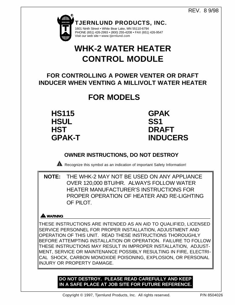
NEW STYLE GAS PRESSURE SWITCH INSTALLATIONThe gas pressure switch is mounted on the casing of the water heater adjacent to the heater's thermostat/gas control valve. Itshould be mounted close enough so that the supplied 1/4" tubing will reach from the gas pressure switch fitting to the thermo-stat/gas valve pressure tap port. The two provided screws are self-tapping and drilling. The screws do not require the use of a drill and their 1/2" length assures that the inner tank will not be penetrated.1. Mount the gas pressure switch by securing it to the heater casing with a screw in each of the two mounting holes.
IMPORTANT: Mount gas pressure switch so that diaphragm is in a VERTICAL position, (See New Switch Diagram).2. Install the supplied 1/8"-NPT pipe plug to the 90o port of the supplied 1/8-NPT black pipe tee, (See New Switch Diagram). Use
thread sealant, do not over tighten.3. Install the 1/8-NPT black pipe tee to the gas pressure switch, (See New Switch Diagram). Use thread sealant, do not over
tighten. CAUTION: Utilize the hex nut on the gas pressure switch when attaching the black pipe tee.4. Install the supplied Brass 1/8-NPT male x ¼" compression fitting to the 1/8-NPT black pipe tee, (See New Switch Diagram ).
Use thread sealant, do not over tighten.5. Remove the PRESSURE TAP plug from the underside of the thermostat/gas control valve and install the supplied Brass
1/8-NPT male x ¼" compression fitting, (See New Switch Diagram). Use thread sealant, do not over tighten.IMPORTANT: DO NOT alter the heater's PILOT GAS LINE, (See New Switch Diagram).
6. Using a tube cutter, cut the appropriate length of the supplied 1/4" tubing to reach from the gas pressure switch fitting to the PRESSURE TAP PORT fitting of the thermostat/gas control valve. Make sure each end of the tubing is not pinched closed.
7. Use the 1/4" tubing to connect gas pressure switch fitting to the PRESSURE TAP PORT fitting on the thermostat/gas control valve.8. Conduct a gas leakage test of all connections as outlined in the latest edition of NFPA 54, ANSI Z223.1, part 4. or local codes.NOTE: A "gauge port" can be accessed by removing the 1/8-NPT pipe plug that is on the 1/8-NPT black pipe tee (attached to
the gas pressure switch).
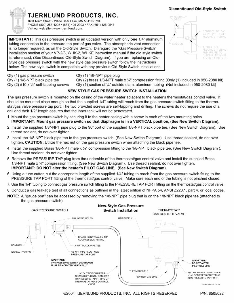
IMPORTANT: This gas pressure switch is an updated version with only one 1/4” aluminumtubing connection to the pressure tap port of gas valve. The atmospheric vent connectionis no longer required, as on the Old-Style Switch. Disregard the “Gas Pressure Switch”installation section of your VP-2/3, WHK-2, WHKE instruction manual if the old style switchis referenced, (See Discontinued Old-Style Switch Diagram). If you are replacing an Old-Style gas pressure switch with the new style gas pressure switch follow the instructionsbelow. The new style switch is compatible with any previous Old-Style Switch installations.
Discontinued Old-Style Switch
DO NOT ALTER
GAS SUPPLY
INTO PRESSURE TAP PORT.
GAS PRESSURE SWITCHGAS CONTROL VALVE
THERMOSTAT/
PILOT GAS LINE
FIGURE 700S107 2/13/04
INSTALL BRASS 1/8-NPT MALEx 1/4" COMPRESSION FITTING
THERMOCOUPLE
BURNER GAS LINE
COMMON
MUST BE MOUNTED VERTICALLY.GAS PRESSURE SWITCH DIAPHRAGMIMPORTANT:
BRASS 1/8-NPT MALE x 1/4"COMPRESSION FITTING
THERMOSTAT / GAS CONTROLTO PRESSURE TAP FITTING OF
1/4" OUTSIDE DIAMETERALUMINUM TUBING - CONNECT
VALVE.
1/8-NPT BLACK PIPE TEE
1/8-NPT PIPE PLUG - NEWPRESSURE TAP PORT
NORMALLY OPEN
MOUNTING HOLES
IMPORTANT:
New-Style Gas Pressure Switch Installation
Copyright © 1997, Tjernlund Products, Inc. All rights reserved. P/N 8504026
REV. 8 9/98
TJERNLUND PRODUCTS, INC.1601 Ninth Street • White Bear Lake, MN 55110-6794PHONE (651) 426-2993 • (800) 255-4208 • FAX (651) 426-9547Visit our web site • www.tjernlund.com
FOR MODELS
HS115 GPAKHSUL SS1HST DRAFT GPAK-T INDUCERS
OWNER INSTRUCTIONS, DO NOT DESTROY
Recognize this symbol as an indication of important Safety Information!
NOTE: THE WHK-2 MAY NOT BE USED ON ANY APPLIANCE OVER 120,000 BTU/HR. ALWAYS FOLLOW WATER HEATER MANUFACTURER’S INSTRUCTIONS FOR PROPER OPERATION OF HEATER AND RE-LIGHTING OF PILOT.
THESE INSTRUCTIONS ARE INTENDED AS AN AID TO QUALIFIED, LICENSEDSERVICE PERSONNEL FOR PROPER INSTALLATION, ADJUSTMENT ANDOPERATION OF THIS UNIT. READ THESE INSTRUCTIONS THOROUGHLYBEFORE ATTEMPTING INSTALLATION OR OPERATION. FAILURE TO FOLLOWTHESE INSTRUCTIONS MAY RESULT IN IMPROPER INSTALLATION, ADJUST-MENT, SERVICE OR MAINTENANCE POSSIBLY RESULTING IN FIRE, ELECTRI-CAL SHOCK, CARBON MONOXIDE POISONING, EXPLOSION, OR PERSONALINJURY OR PROPERTY DAMAGE.
!
DO NOT DESTROY. PLEASE READ CAREFULLY AND KEEPIN A SAFE PLACE AT JOB SITE FOR FUTURE REFERENCE.
WHK-2 WATER HEATER CONTROL MODULE
FOR CONTROLLING A POWER VENTER OR DRAFT INDUCER WHEN VENTING A MILLIVOLT WATER HEATER
TABLE OF CONTENTS
Pilot Outage.....................................................................................................................................................................1General Cautions & Installation Restrictions...............................................................................................................1, 2Installation
Actuation & Safety Controls..............................................................................................................................2Solenoid Valve ..................................................................................................................................................2Gas Pressure Switch ....................................................................................................................................2, 3Linear Limit Spill Switch....................................................................................................................................3
Electrical Wiring 115VAC interlock with HSUL, GPAK Power Venters or Draft Inducers with 950-1040 24/115 VAC Relay......4115VAC interlock with HST, GPAK-T Power Venters or Draft Inducers with 950-1067 Relay/Timer ...............5115VAC interlock with HS115 Series Power Venters or Draft Inducers............................................................6System Schematic/WHK-2 Operation ...............................................................................................................6WHK-2/HSUL or GPAK Series Furnace or Boiler & Water Heater Connection Diagram.................................7WHK-2/HST or GPAK-T Series Furnace or Boiler & Water Heater Connection Diagram................................7WHK-2/SideShot Furnace or Boiler & Water Heater Connection Diagram ......................................................824 VAC Water Heater Connections ..................................................................................................................8
Operation Circuit Check ..................................................................................................................................................9Safety Interlock Test ........................................................................................................................................................9Combustion Air Test ........................................................................................................................................................9Post Purge Timer Adjustment .........................................................................................................................................9Troubleshooting......................................................................................................................................................10, 11Warranty Claim Procedure ............................................................................................................................................12Typical Applications ......................................................................................................................................................13
IN THE EVENT OF PILOT OUTAGE
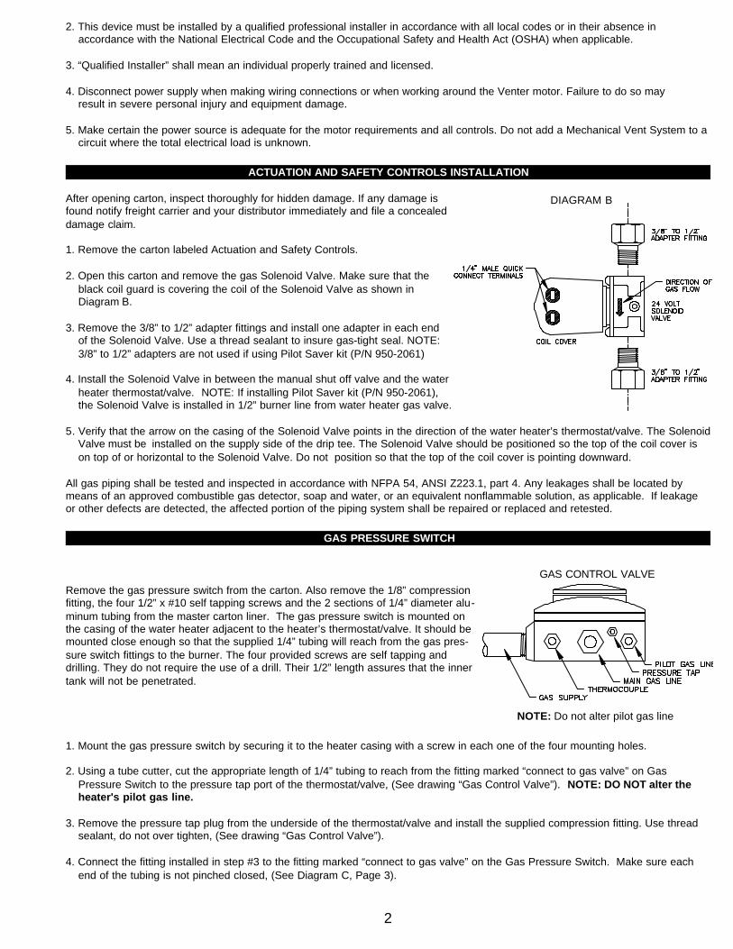
1. Push the reset button in the center of the Linear Limit spillage sensing switch located on the draft hood on the top of the water heater, (See Diagram A)
2. Turn the gas pilot knob at the top of water heater gas valve to “OFF” position.
Gas pilot knob MUST REMAIN IN “OFF” POSITION FOR FIVE MINUTES BEFOREPILOT IS RE-LIT. Perform steps 3 & 4 while waiting.
3. Visually verify that there is 115 volt power established to the Power Venter.(Check fuse or circuit breaker, wall plug and electrical connections).
4. Visually verify that all connections of the control cord circuit are intact.
5. Follow water heater manufacturer’s re-lighting instructions attached to water heater or located in water heater owner’s manual.
USER NOTE:Since the Power Venter/Draft Inducer cannot operate during a power outage, the safety interlock controls are designed to prohibit gasflow to the water heater. Follow the above procedures and water heater manufacturer’s instructions for relighting the pilot when powerhas been restored.
OPTIONAL PILOT SAVER KIT AVAILABLEThe optional Pilot Saver Kit (P/N: 950-2061) allows for Solenoid Valve to be installed in 1/2” burner gas line from water heater gasvalve which eliminates pilot outages caused by power interruptions.
INSTALLATION RESTRICTIONS
1. Failure to install, maintain and/or operate this device in accordance with manufacturer’s instructions may result in conditions which can produce bodily injury and property damage.
1
IMPORTANT
NOTE: These instructions do NOT cover the installation of the Power Venter/Draft Inducer. Install the Power Venter/DraftInducer first, according to the manufacturer’s instructions before proceeding with the installation of the WHK-2. Do not con-nect 115V wiring of Power Venter/Draft Inducer. The WHK-2 is designed to interlock a millivolt appliance of up to 120,000BTU’s with a Power Venter/Draft Inducer. The WHK-2 can be wired two different ways.
A. To interlock a single millivolt appliance, such as a water heater.B. To interlock a millivolt appliance and provide the primary power so that one Power Venter/Draft Inducer can vent both a
water heater and a furnace/boiler.
DIAGRAM A
2. This device must be installed by a qualified professional installer in accordance with all local codes or in their absence in accordance with the National Electrical Code and the Occupational Safety and Health Act (OSHA) when applicable.
3. “Qualified Installer” shall mean an individual properly trained and licensed.
4. Disconnect power supply when making wiring connections or when working around the Venter motor. Failure to do so may result in severe personal injury and equipment damage.
5. Make certain the power source is adequate for the motor requirements and all controls. Do not add a Mechanical Vent System to a circuit where the total electrical load is unknown.
ACTUATION AND SAFETY CONTROLS INSTALLATION
After opening carton, inspect thoroughly for hidden damage. If any damage isfound notify freight carrier and your distributor immediately and file a concealeddamage claim.
1. Remove the carton labeled Actuation and Safety Controls.
2. Open this carton and remove the gas Solenoid Valve. Make sure that the black coil guard is covering the coil of the Solenoid Valve as shown in Diagram B.
3. Remove the 3/8” to 1/2” adapter fittings and install one adapter in each end of the Solenoid Valve. Use a thread sealant to insure gas-tight seal. NOTE: 3/8” to 1/2” adapters are not used if using Pilot Saver kit (P/N 950-2061)
4. Install the Solenoid Valve in between the manual shut off valve and the waterheater thermostat/valve. NOTE: If installing Pilot Saver kit (P/N 950-2061), the Solenoid Valve is installed in 1/2” burner line from water heater gas valve.
5. Verify that the arrow on the casing of the Solenoid Valve points in the direction of the water heater’s thermostat/valve. The SolenoidValve must be installed on the supply side of the drip tee. The Solenoid Valve should be positioned so the top of the coil cover is on top of or horizontal to the Solenoid Valve. Do not position so that the top of the coil cover is pointing downward.
All gas piping shall be tested and inspected in accordance with NFPA 54, ANSI Z223.1, part 4. Any leakages shall be located bymeans of an approved combustible gas detector, soap and water, or an equivalent nonflammable solution, as applicable. If leakageor other defects are detected, the affected portion of the piping system shall be repaired or replaced and retested.
GAS PRESSURE SWITCH
Remove the gas pressure switch from the carton. Also remove the 1/8” compressionfitting, the four 1/2” x #10 self tapping screws and the 2 sections of 1/4” diameter alu-minum tubing from the master carton liner. The gas pressure switch is mounted onthe casing of the water heater adjacent to the heater’s thermostat/valve. It should bemounted close enough so that the supplied 1/4” tubing will reach from the gas pres-sure switch fittings to the burner. The four provided screws are self tapping anddrilling. They do not require the use of a drill. Their 1/2” length assures that the innertank will not be penetrated.
1. Mount the gas pressure switch by securing it to the heater casing with a screw in each one of the four mounting holes.
2. Using a tube cutter, cut the appropriate length of 1/4” tubing to reach from the fitting marked “connect to gas valve” on Gas Pressure Switch to the pressure tap port of the thermostat/valve, (See drawing “Gas Control Valve”). NOTE: DO NOT alter the heater's pilot gas line.
3. Remove the pressure tap plug from the underside of the thermostat/valve and install the supplied compression fitting. Use thread sealant, do not over tighten, (See drawing “Gas Control Valve”).
4. Connect the fitting installed in step #3 to the fitting marked “connect to gas valve” on the Gas Pressure Switch. Make sure each end of the tubing is not pinched closed, (See Diagram C, Page 3).
2
DIAGRAM B
GAS CONTROL VALVE
NOTE: Do not alter pilot gas line

5. Measure and cut an appropriate length of tubing to reach from the fitting marked “warning” to the burner of the heater on Gas Pressure Switch. Connect to Gas Pressure Switch and route to burner area.
NOTE: The Gas Pressure Switch has a built in pressure tap marked “gauge port” for future gas pressure testing, (See Diagram D).
LINEAR LIMIT SPILLAGE SENSING SWITCH
PURPOSE:To provide a means for appliance shut-down in the event of flueblockage or Power Venter/Draft Inducer failure.
OPERATION:When concentrated spillage of the products of combustion occursfrom the draft hood, the Linear Limit sensing switch circuit will openpreventing burner operation.
1. Attach the Linear Limit sensing switch mounting bracket to the top of the water heater using the sheet metal screws provided. The Linear Limit bracket should be approximately 1/2” from the draft hood, (See Diagram E).
2. Attach the three Linear Limit capillary mounting brackets around the draft hood, equally spaced.
3. Insert the Linear Limit spillage sensing switch capillary into the “U” of the Linear Limit brackets outlining the perimeter of the draft hood. The Linear Limit capillary may be overlapped if necessary, (See Diagram F). IMPORTANT: DO NOT CUT THE CAPILLARY, itwill be destroyed and water heater will be disabled.
4. Route the Linear Limit spillage switch cable down the water heater casing locating the end near the Solenoid Valve. Secure it with the cable clamps and self drilling screws provided.
3
DIAGRAM E
TOP VIEW
DIAGRAM F
DIAGRAM DDIAGRAM C
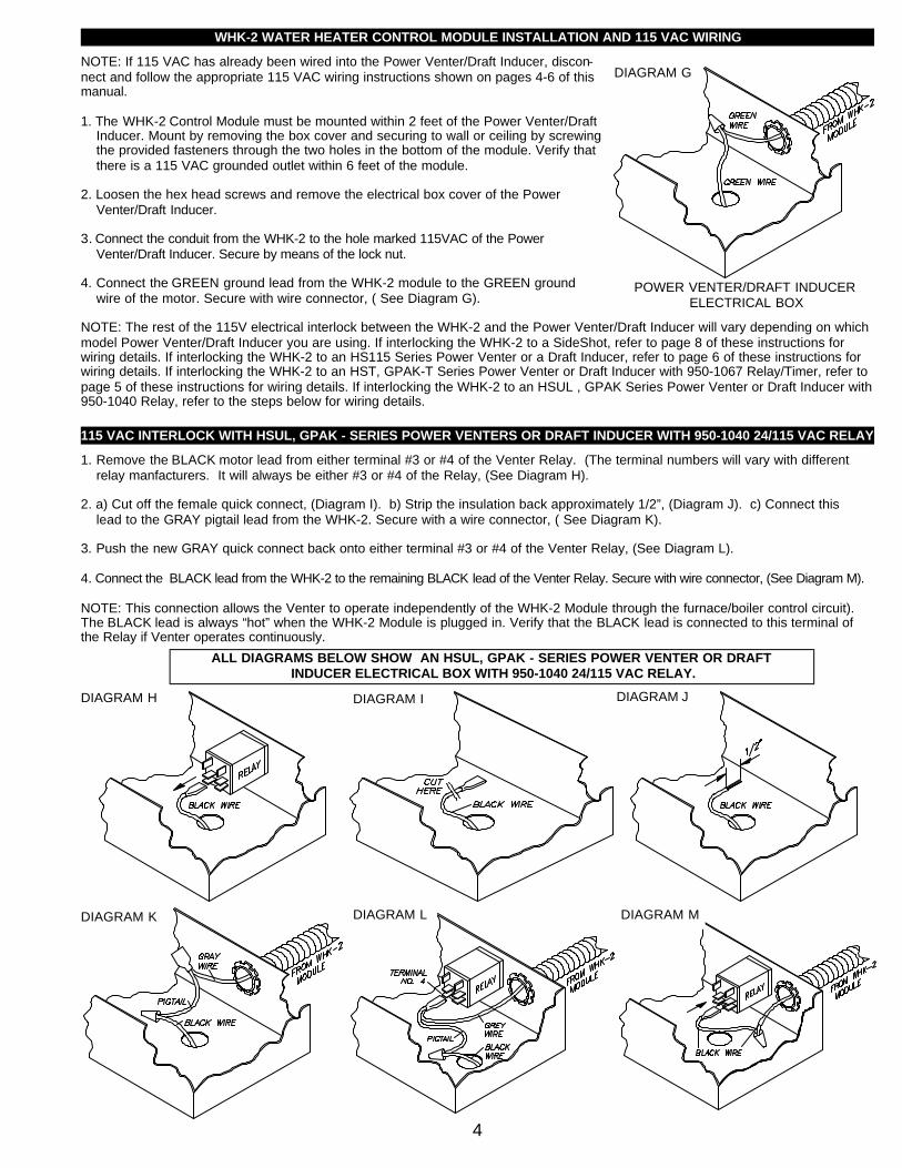
WHK-2 WATER HEATER CONTROL MODULE INSTALLATION AND 115 VAC WIRING
NOTE: If 115 VAC has already been wired into the Power Venter/Draft Inducer, discon-nect and follow the appropriate 115 VAC wiring instructions shown on pages 4-6 of thismanual.
1. The WHK-2 Control Module must be mounted within 2 feet of the Power Venter/Draft Inducer. Mount by removing the box cover and securing to wall or ceiling by screwing the provided fasteners through the two holes in the bottom of the module. Verify that there is a 115 VAC grounded outlet within 6 feet of the module.
2. Loosen the hex head screws and remove the electrical box cover of the Power Venter/Draft Inducer.
3. Connect the conduit from the WHK-2 to the hole marked 115VAC of the Power Venter/Draft Inducer. Secure by means of the lock nut.
4. Connect the GREEN ground lead from the WHK-2 module to the GREEN ground wire of the motor. Secure with wire connector, ( See Diagram G).
NOTE: The rest of the 115V electrical interlock between the WHK-2 and the Power Venter/Draft Inducer will vary depending on whichmodel Power Venter/Draft Inducer you are using. If interlocking the WHK-2 to a SideShot, refer to page 8 of these instructions forwiring details. If interlocking the WHK-2 to an HS115 Series Power Venter or a Draft Inducer, refer to page 6 of these instructions forwiring details. If interlocking the WHK-2 to an HST, GPAK-T Series Power Venter or Draft Inducer with 950-1067 Relay/Timer, refer topage 5 of these instructions for wiring details. If interlocking the WHK-2 to an HSUL , GPAK Series Power Venter or Draft Inducer with950-1040 Relay, refer to the steps below for wiring details.
115 VAC INTERLOCK WITH HSUL, GPAK - SERIES POWER VENTERS OR DRAFT INDUCER WITH 950-1040 24/115 VAC RELAY
1. Remove the BLACK motor lead from either terminal #3 or #4 of the Venter Relay. (The terminal numbers will vary with different relay manfacturers. It will always be either #3 or #4 of the Relay, (See Diagram H).
2. a) Cut off the female quick connect, (Diagram I). b) Strip the insulation back approximately 1/2”, (Diagram J). c) Connect this lead to the GRAY pigtail lead from the WHK-2. Secure with a wire connector, ( See Diagram K).
3. Push the new GRAY quick connect back onto either terminal #3 or #4 of the Venter Relay, (See Diagram L).
4. Connect the BLACK lead from the WHK-2 to the remaining BLACK lead of the Venter Relay. Secure with wire connector, (See Diagram M).
NOTE: This connection allows the Venter to operate independently of the WHK-2 Module through the furnace/boiler control circuit).The BLACK lead is always “hot” when the WHK-2 Module is plugged in. Verify that the BLACK lead is connected to this terminal ofthe Relay if Venter operates continuously.
4
DIAGRAM G
DIAGRAM H
POWER VENTER/DRAFT INDUCERELECTRICAL BOX
DIAGRAM I
DIAGRAM K
DIAGRAM J
DIAGRAM L
ALL DIAGRAMS BELOW SHOW AN HSUL, GPAK - SERIES POWER VENTER OR DRAFTINDUCER ELECTRICAL BOX WITH 950-1040 24/115 VAC RELAY.
DIAGRAM M

5. Connect the WHITE lead from the WHK-2 to the WHITE motor lead. Secure with a wire connector, (See Diagram N).
6. Replace both electrical box covers.
NOTE: When using the HSUL or GPAK Series for a water heater only, the ORANGE, YELLOW and BLUE wires in the Power Venter are not used.
7. Skip to Page 8, “24 VAC Connection To Water Heater Controls”.
115 VAC INTERLOCK WITH HST, GPAK-T POWER VENTERS OR DRAFT INDUCER WITH 950-1067 RELAY/TIMER
1. Remove the BLACK motor lead from terminal BLK MTR of the Venter Relay/Timer, (See Diagram O)
2. a) Cut off the female quick connect, (Diagram P). b) Strip the insulation back approximately 1/2”, (Diagram Q). c) Connect this lead to the GRAY pigtail lead from the WHK-2. Secure with a wire connector, (Diagram R).
3. Push the new GRAY quick connect back onto terminal BLK. MTR. of the Venter Relay/Timer, (See Diagram S).
4. Connect the BLACK lead that is connected to terminal L1 of the Venter Relay/Timer to the BLACK wire from the WHK-2 Module, secure with a wire connector, (See Diagram T).
NOTE: This connection allows the Venter to operate independently of the WHK-2 Module through the furnace/boiler control circuit.
5. Connect the WHITE lead from the WHK-2 to the WHITE lead connected to terminal L2 of the Venter Relay/Timer and the WHITE motor lead. Secure with a wire connector, (See Diagram U).
6. Replace both electrical box covers.
7. Skip to Page 8, “24 VAC Connection To Water Heater Controls”.115
5
DIAGRAM N
DIAGRAM R
DIAGRAM U
DIAGRAM P DIAGRAM Q
NOTE: When using the HST, GPAK-T or DraftInducer with a 950-1067 Relay/Timer for awater heater only, the wires from the #4 & #5terminals on Relay/Timer and the YELLOWand BLUE wires from the Fan Proving Switch inPower Venter are not used.
ALL DIAGRAMS BELOW SHOW AN HST, GPAK-T POWER VENTER OR DRAFT INDUCER ELECTRICAL BOX WITH950-1067 RELAY/TIMER. NOTE: GPAK-T RELAY/TIMER MAY LOOK DIFFERENT THAN SHOWN, HOWEVER,TERMINAL DESIGNATIONS ARE THE SAME.
DIAGRAM TDIAGRAM S
DIAGRAM O

115 VAC INTERLOCK WITH HS115 - SERIES POWER VENTERS AND 115 VAC CONTROLLED DRAFT INDUCERS
1. Connect the GRAY wire from the WHK-2 Module to the BLACK 115 VAC motor lead of the Power Venter or Draft Inducer.
NOTE: Cut the quick connect and cap with wire connector.
2. Connect the WHITE wire from the WHK-2 to the WHITE wire from the Power Venter or Draft Inducer motor.
3. IMPORTANT: The BLACK wire from the WHK-2 module is not used in these applications. Cut stripped end of this wire and wrap with suitable electrical tape to prevent contact with other live connections in wiring box.
NOTE: When using the HS115 for a water heater only, the YELLOW and BLUE wires in the Power Venter are not used.
WHK-2 WIRING
WHK-2 OPERATION
WHK-2 SEQUENCE OF OPERATION:1. Water heater calls for heat which sends a small amount of gas from the water heater pressure tap to the Gas Pressure Switch.
2. Gas Pressure Switch closes completing the circuit between the WHK-2 Transformer and terminals 4 & 5 of WHK-2 Relay/Timer.
3. When terminals 4 & 5 of the WHK-2 Relay/Timer receive 24V, an internal switch of the WHK-2 Relay/Timer closes between L1 and BLK. MTR. sending current to the Gray of the WHK-2 metal conduit.
4. When the water heater thermostat is satisfied the Gas Pressure Switch will open, disrupting 24V to terminals 4 & 5 of the WHK-2 Relay/Timer. The internal switch between L1 and BLK. MTR. of the WHK-2 Relay/Timer remains closed for an adjustable time allowing the Power Venter/Draft Inducer to continue operating.
WHK-2 SAFETY OPERATION:If the Venter fails to operate, flue gas spillage will occur from the water heater draft hood. The heat from the flue gas will cause theLinear Limit switch to open, opening the circuit to the Solenoid Valve. The Solenoid Valve will close disrupting the gas supply to thewater heater.
OPERATIONAL NOTES:The BLACK wire from the WHK-2 is always “hot” and is not used if venting a water heater only. If common venting two appliances,the venter will only post purge with the water heater.
6

7
WHK-2 CONNECTED TO AN HSUL, GPAK - SERIES POWER VENTER OR DRAFT INDUCER WITH 950-1040 24/115 VAC RELAY (FURNACE OR BOILER AND WATER HEATER COMMON VENTED)
WHK-2 CONNECTED TO AN HST, GPAK-T SERIES POWER VENTER OR DRAFT INDUCER WITH 950-1067 RELAY/TIMER (FURNACE OR BOILER AND WATER HEATER COMMON VENTED)
NOTE: On the GPAK-T Series thewire color from terminal # 4 ofRelay/Timer is BLUE. The wirefrom terminal # 5 is ORANGE.

24 VAC CONNECTION TO WATER HEATER CONTROLS
Route the 25’ control cable to the water heater. Route control cable back to the heater controls along the ceiling or joists, taking carenot to come closer than 6” to the vent pipe or any other potentially hot surface.In many cases, the gas supply piping can be used as a routing path from the ceiling down to the controls, using the supplied nylonties to secure the cable.
NOTE: If the distance between the WHK-2 Control Module and the heater controls is greater than the length of the cable, splice asection of 3 conductor PVC sheathed, 105 degree C thermostat cable to the supplied cable. Make sure the colored leads remain consistent.
ACTUATING AND SAFETY CONTROL CIRCUIT CONNECTIONS
1. Push the BLACK piggy-back lead from the 6’ 18/2 Linear Limit sensing switch cable onto the common terminal of the Gas PressureSwitch, (Diagram V).
2. Push the remaining BLACK lead from the 6’ 18/2 sensing switch cable onto one of the terminals on the Solenoid Valve, (Diagram W).3. Push the YELLOW lead from the 25’ control cable onto the remaining terminal on the Solenoid Valve, (Diagram W).4. Push the RED lead from the 25’ control cable onto the piggyback terminal joined with common on the Gas Pressure Switch, (Diagram V).5. Push the BLUE lead from the 25’ control cable onto the normally open terminal on the Gas Pressure Switch, (Diagram V).6. Plug the power cord from the WHK-2 into a grounded 115 VAC outlet. Verify that the outlet is powered through a 15 amp circuit breaker.
NOTE: The Power Venter may operate from 1 to 10 minutes when power is first established. This is due to any remaining time left onthe “post-purge” cycle of Relay/Timer after power has been interrupted. Wait until the Power Venter shuts off before continuing.
8
WHK-2 CONNECTED TO AN SS1(FURNACE OR BOILER AND WATER HEATER COMMON VENTED)
DIAGRAM V DIAGRAM W

OPERATION CIRCUIT CHECK
1. Place water heater in operation. A. The Power Venter should operate.
2. Turn gas pilot knob to “pilot”. B. The Power Venter should continue to operate for approximately 1 minute. The length of the post-purge cycle can be varied by adjusting the post purge control. See “Post Purge Timer Adjustment” on bottom of page.
3. Repeat steps #1 and #2 to assure proper operation.
SAFETY INTERLOCK TEST
1. Remove the BLUE lead from the normally open contact of the Gas Pressure Switch. (This will disable the Power Venter).
2. Adjust the heater’s thermostat or run hot water until full burner operation occurs.
3. Within 3 minutes the Linear Limit spillage sensing switch circuit should disrupt power to the Gas Solenoid Valve, stopping the supply of gas to water heater.
4. IMPORTANT: Wait 5 minutes and push the reset button on the Linear Limit spillage sensing switch.
5. Reconnect the BLUE lead to the normally open terminal of the Gas Pressure Switch.
6. Re-light pilot following the water heater manufacturer’s instructions.
7. Extinguish the pilot with the burner off. Determine, after 3 minutes that there is no gas flow to the main burner. If gas flow to the main burner is detected, replace the water heater gas valve immediately.
COMBUSTION AIR TEST
The Linear Limit spillage sensing switch is designed to alert the user to a potentially hazardous condition. It is not designed to, andcannot replace, regular vent system inspection, appliance servicing and combustion testing. DO NOT USE IT AS A SUBSTITUTEFOR PROFESSIONAL APPLIANCE MAINTENANCE.
1. Close all doors and windows of the building. If appliance is installed in utility room or closet, close the entrance door to this room. Close fireplace dampers.
2. Turn on clothes dryer. Turn on all exhaust fans, such as range hoods, bathroom exhausts and whole house fans to maximum speeds.
3. Following the water heater manufacturer's instructions, place the appliance in operation, set thermostat for continuous operation.
4. Allow fans and appliance to operate for 5 minutes.
5. Tripping of the Linear Limit spillage sensing switch during 5 minute appliance operation indicates an unsafe operating condition. Turn off fuel supply to appliance and DO NOT OPERATE UNTIL UNSAFE VENTING CONDITION IS INVESTIGATED BY A PROFESSIONAL CONTRACTOR OR UTILITY SERVICE PERSONNEL.
6. Return all windows, doors and fans to their previous conditions of use.
POST PURGE TIMER ADJUSTMENT
1. Disrupt 115 VAC power to the Power Venter.
2. Loosen the two screws and remove junction box cover.
3. The post purge timer is marked “adjustable delay control”. The adjustment is made by turning the small slotted screw. Turn it counter clockwise to increase the delay, clockwise to decrease the delay.(Nominal adjustment range is 1 to 10 minutes) NOTE: Do not overturn adjustment screw on Relay/Timer. This will damage Relay/Timer and void warranty.
9

WHK-2 TROUBLESHOOTING
10
NOTE: All troubleshooting diagrams below are for a Furnace or Boiler & Water Heater common vented using a WHK-2 and HSUL,GPAK-J,1 Series Power Venter or Draft Inducer with 950-1040 24/115 VAC Relay.
SYMPTOM 1: HSUL, GPAK - SERIES POWER VENTER OR DRAFT INDUCER OPERATES CONTINUOUSLY. BEFORE CONTINUING, THE VENTER SHOULD BE OPERATING WITH NEITHER APPLIANCE CALLING FOR HEAT.
Check wiring inside Venter electrical box from WHK-2 metal conduit.1) Gray from WHK-2 should be connected to thick Black Venter motor
wire and terminal 3 or 4 on Venter Relay.2) Black from WHK-2 should be connected to thin Black wire on Relay.3) White from WHK-2 should be connected to White Venter motor wire.
Yes
Yes
Yes
YesYes
Yes
YesNo
No
No
No
No
No
No
With the Venter Operating, remove the Blue wire from WHK-2 Relay/Timer. The Venter shouldshut off within 10 minutes.
Reconnect the Blue wire on the WHK-2 Relay/Timer, the Ventershould start operation again. Remove the Blue wire from WaterHeater Gas Pressure Switch. The Venter should shut off within 10minutes.
With the Blue wire still removed from WHK-2 Relay/Timer andthe Venter operating, remove the thin Black wire from theVenter Relay. The Venter should shut off within 10 minutes.
Replace WHK-2Relay/TimerPart #950-1067
With the Blue and thin Blackwires still removed from theprevious step, remove theGray and Blue wires fromthe Venter Relay. Check forcontinuity between theVenter Relay terminalswhich the Gray and thinBlack wires were connectedto.
Replace VenterRelay. Part#950-1040
The Venter is not wired to theFurnace/Boiler correctly.Rewire per the WHK-2instructions.
Remove all tubing from Gas PressureSwitch and check Switch for continuity.
Replace WHK-2Control Cable. Part#950-2060.
Replace WHK-2 GasPressure Switch.Part #950-2080.
Check WHK-2 GasPressure Switch tubingfor blockage.
Repair or replacetubing.
Check Water HeaterPressure Tap Port forpressure with the burneroff.
Contact Waterheater manufacturerfor assistance. Contact Tjernlund Products,
Inc. at 1-800-255-4208 forassistance.
The following guide is intended to be used if a problem occurs during the use of the WHK-2 and HSUL, GPAK-J,1 Series PowerVenter or Draft Inducer with 950-1040 24/115 VAC Relay. At several steps throughout the guide you will be required to measure voltage.
Extreme caution must be exercised to prevent injury. If you are unable to determine the defective part with the use of this guide,call your Tjernlund distributor or Tjernlund Products direct at 1-800-255-4208 for further assistance.

11
SYMPTOM 2: HSUL, GPAK - SERIES POWER VENTER OR DRAFT INDUCER OPERATES WITH FURNACE OR BOILER NOTWITH WATER HEATER. BEFORE CONTINUING, THE WHK-2 SHOULD HAVE POWER AND THE FURNACE ORBOILER SHOULD NOT BE CALLING FOR HEAT.
Repair or replace tubing.
Yes
Yes
Yes Yes
Yes
Yes
Yes
No
No
No
No
No
No
No
Check the WHK-2 Gas Pressure switch tubing for blockage.
Check Water Heater Pressuretap Port for pressure with theWater Heater burner on.Pressure should be present.
Replace WHK-2 GasPressure Switch.Part #950-2080
Contact Water Heatermanufacturer for assis-tance.
With the Red, Black and Blue wires jumped at the WHK-2Gas Pressure Switch, check for 24V at terminals 4 & 5 of theWHK-2 Relay/Timer.
Replace WHK-2 Relay/TimerPart #950-1067
Check for 24V on the Red andYellow wires of WHK-2 trans-former.
Replace WHK-2 25’Control Cable.Part #950-2060
Replace WHK-2Transformer.Part #950-2030
Check wiring inside Venter electrical box from WHK-2 metal conduit.1) Gray from WHK-2 should be connected to thick Black Venter motor
wire and terminal 3 or 4 on Venter Relay.2) Black from WHK-2 should be connected to thin Black wire on Venter Relay.3) White from WHK-2 should be connected to White Venter motor wire.
Jump the Red. Black and Blue wires on Water Heater Gas Pressure Switch. TheVenter should start.
SYMPTOM 3: HSUL, GPAK - SERIES POWER VENTER OR DRAFT INDUCER OPERATES WITH WATER HEATER NOT WITH FURNACE OR BOILER. BEFORE CONTINUING, THE WHK-2 SHOULD HAVE POWER, THE WATER HEATER SHOULD BE OFF AND THE FURNACE OR BOILER SHOULD BE CALLING FOR HEAT.
Check wiring inside Venter electrical box from WHK-2 metal conduit.1) Gray from WHK-2 should be connected to thick Black Venter motor wire and
terminal 3 or 4 on Relay.2) Black from WHK-2 should be connected to thin Black wire on Venter Relay.3) White from WHK-2 should be connected to white Venter motor wire.
With the Furnace/Boiler calling for heat, check for 24V on the Blue and Orangewires of Venter Relay. 24V should be present.
The Venter is not wired to the Furnace or boiler correctly ormalfunction of Furnace/Boiler controls. Rewire per the WHK-2instructions or contact Furnace/Boiler manufacturer for assis-tance.
With the Blue and Orange wires connected to terminals 7 & 8of Venter Relay and the Furnace/Boiler calling for heat,remove the Gray and thin Black wires from the Venter Relayand check for continuity between the terminals which theGray and thin Black wires wire connected to. There should becontinuity.
Contact TjernlundProducts, Inc. at 1-800-255-4208 for assistance.
Replace Venter Relay.Part #950-1040

LIMITED PARTS WARRANTY AND CLAIM PROCEDURE
Tjernlund Products, Inc. warrants the components of the WHK-2 for one year from date of installation. This warranty covers defects inmaterial and workmanship. This warranty does not cover normal maintenance, transportation or installation charges for replacementparts or any other service calls or repairs. This warranty DOES NOT cover the complete WHK-2 if it is operative, except for thedefective part.
Tjernlund Products, Inc. will issue credit or provide a free part to replace one that becomes defective during the one year warranty peri-od. If the part is over 18 months old, proof of date of the installation in the form of the contractor sales/installation receipt is necessaryto prove the unit has been in service for under one year. All receipts should include the date code of the WHK-2 to ensure that the defec-tive component corresponds with the complete unit. This will help preclude possible credit refusal.
1.) Follow troubleshooting guide to determine defective component. If unable to determine faulty component, contact your Tjernlund distributor or Tjernlund Products Technical Customer Service Department at 1-800-255-4208 for troubleshooting assistance.
2.) After the faulty component is determined, return it to your Tjernlund distributor for replacement. Please include WHK-2 date code component was taken from. The date code is located on the Electrical Box coverplate. If the date code is older than 18months you will need to provide a copy of the original installation receipt to your distributor. Credit or replacement will only be issued to a Tjernlund distributor after the defective part has been returned prepaid to Tjernlund.
COVERED PARTS
Component Part Number24V Solenoid Valve 950-2040Gas Pressure Switch 950-208025’ Control Cord 950-206024V Transformer 950-2030Relay/Timer 950-1067Linear Limit Spill Switch 950-2064Pilot Saver Kit (Optional) 950-2061
WHAT IS NOT COVERED
Product installed contrary to our installation instructionsProduct that has been altered, neglected or misusedProduct that has been wired incorrectlyProduct that has been damaged by a malfunctioning or mistuned burnerAny freight charges related to the return of the defective partAny labor charges related to evaluating and replacing the defective part
12
TJERNLUND LIMITED ONE YEAR WARRANTY
Tjernlund Products, Inc. warrants to the original purchaser of this product that the product will be free from defects due to faultymaterial or workmanship for a period of (1) year from the date of original purchase or delivery to the original purchaser, whichev-er is earlier. Remedies under this warranty are limited to repairing or replacing, at our option, any product which shall, within theabove stated warranty period, be returned to Tjernlund Products, Inc. at the address listed below, postage prepaid. THERE ARENO WARRANTIES WHICH EXTEND BEYOND THE DESCRIPTION ON THE FACE HEREOF, AND TJERNLUND PRODUCTS,INC. EXPRESSLY DISCLAIMS LIABILITY FOR INCIDENTAL OR CONSEQUENTIAL DAMAGES ARISING FROM THE USE OFTHIS PRODUCT. THIS WARRANTY IS IN LIEU OF ALL OTHER EXPRESS WARRANTIES AND NO AGENT IS AUTHORIZEDTO ASSUME FOR US ANY LIABILITY ADDITIONAL TO THOSE SET FORTH IN THIS LIMITED WARRANTY. IMPLIED WAR-RANTIES ARE LIMITED TO THE STATED DURATION OF THIS LIMITED WARRANTY. Some states do not allow limitation onhow long an implied warranty lasts, so that limitation may not apply to you. In addition, some states do not allow the exclusionor limitation of incidental or consequential damages, so that above limitation or exclusion may not apply to you. This warrantygives you specific legal rights and you may also have other rights which may vary from State to State. Send all inquiries regard-ing warranty work to Tjernlund Products, Inc. 1601 9th Street, White Bear Lake, MN 55110-6794. Phone (651) 426-2993 • (800) 255-4208 • Fax (651) 426-9547.

TYPICAL APPLICATION
13
FURNACE OR BOILER WITH MILLIVOLT WATER HEATER
MILLIVOLT WATER HEATER