distance protection of cross bonded cable systems...
TRANSCRIPT

1
Distance Protection of Cross‐Bonded Transmission Cable‐Systems
Distance Protection of Cross‐Bonded Transmission Cable‐Systems
by
Claus Leth Bak, Dept. of Energy Technology, Aalborg University
Christian Flytkjær JensenEnerginet.dk

2
Distance Protection of Cross‐Bonded Transmission Cable‐SystemsOutline
• Introduction• Fault loop impedance on cross‐bonded cable systems
– Double‐sided infeed– Long cables– Trefoil formation– Field‐ and substation grounding resistances and ground resistivity– Fault resistance between core and sheath– Core to sheath to ground faults– Hybrid lines
• Discussions
Outline of the presentation

3
Distance Protection of Cross‐Bonded Transmission Cable‐SystemsIntroduction
The cable act plan as decided byDanish government undergroundsmost of the transmission networkin the years to come.
Distance protection is widely usedin Denmark and will play a role asback‐up protection in a cable basedtransmission network. Hybrid linesalso uses distance protection.
Danish transmission network 2030
4
Distance Protection of Cross‐Bonded Transmission Cable‐SystemsFault loop impedance on cross‐bonded cable systems
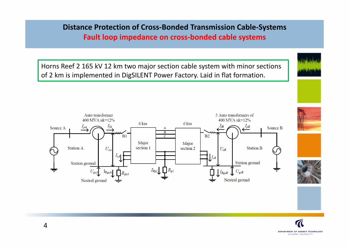
Horns Reef 2 165 kV 12 km two major section cable system with minor sections of 2 km is implemented in DigSILENT Power Factory. Laid in flat formation.

5
Distance Protection of Cross‐Bonded Transmission Cable‐SystemsFault loop impedance on cross‐bonded cable systems
Cross‐bonding scheme
Distance protection relies on a linear relation between measured impedanceand distance to fault. We would not expect this from a crossbonded cable systemdue to the shifting of the sheath current.

6
Distance Protection of Cross‐Bonded Transmission Cable‐SystemsFault loop impedance on cross‐bonded cable systems
Single‐ended infeed
7
Distance Protection of Cross‐Bonded Transmission Cable‐SystemsFault loop impedance on cross‐bonded cable systems
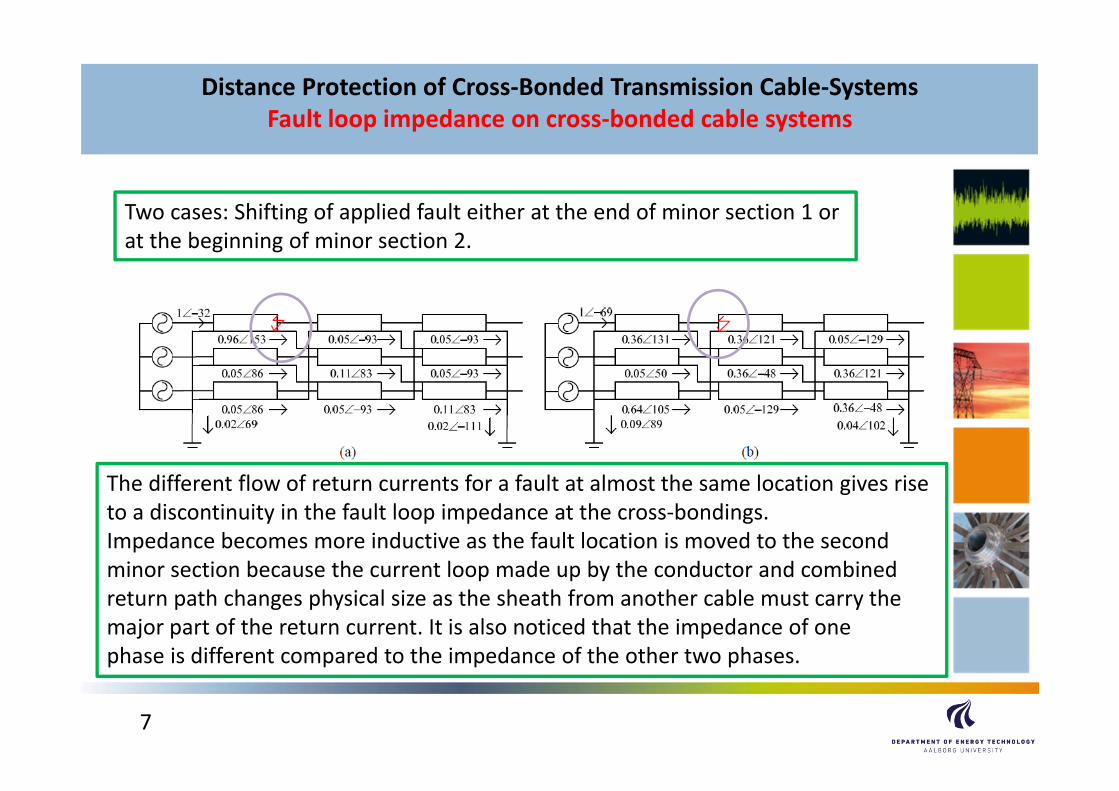
Two cases: Shifting of applied fault either at the end of minor section 1 orat the beginning of minor section 2.
The different flow of return currents for a fault at almost the same location gives riseto a discontinuity in the fault loop impedance at the cross‐bondings.Impedance becomes more inductive as the fault location is moved to the second minor section because the current loop made up by the conductor and combined return path changes physical size as the sheath from another cable must carry the major part of the return current. It is also noticed that the impedance of one phase is different compared to the impedance of the other two phases.
8
Distance Protection of Cross‐Bonded Transmission Cable‐SystemsFault loop impedance on cross‐bonded cable systems
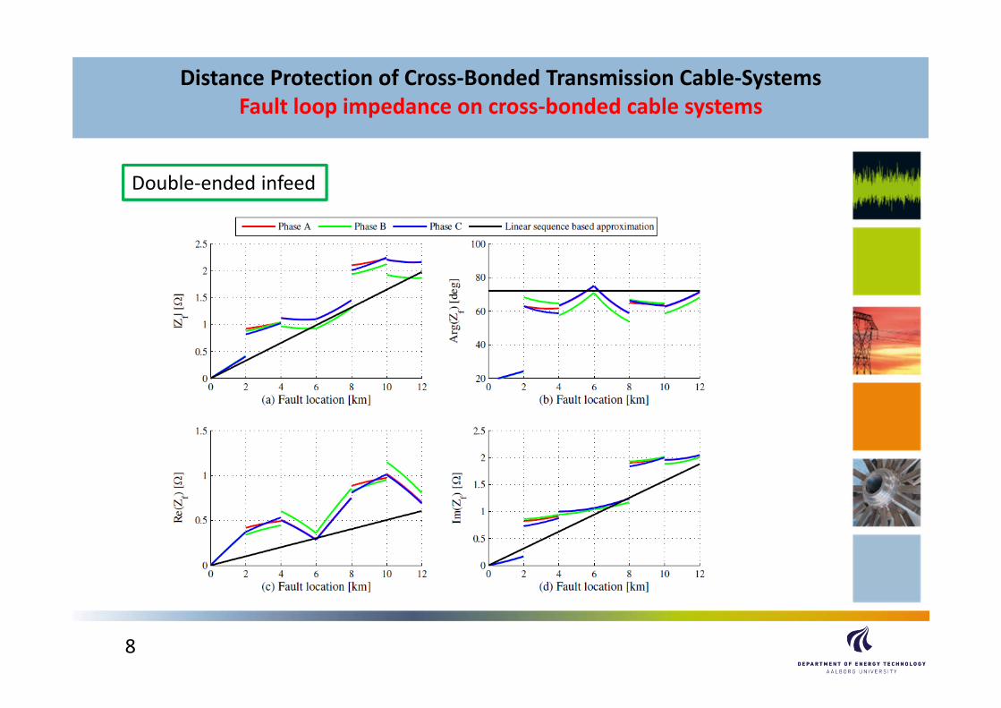
Double‐ended infeed
9
Distance Protection of Cross‐Bonded Transmission Cable‐SystemsFault loop impedance on cross‐bonded cable systems
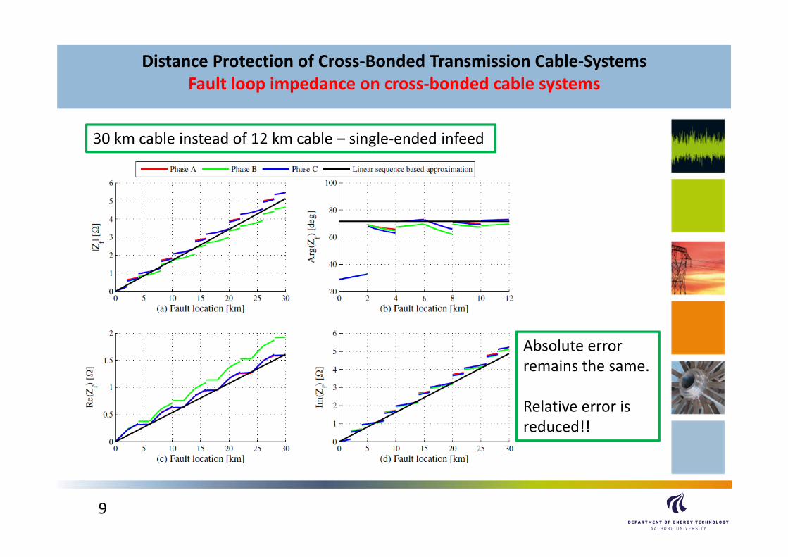
30 km cable instead of 12 km cable – single‐ended infeed
Absolute errorremains the same.
Relative error is reduced!!
10
Distance Protection of Cross‐Bonded Transmission Cable‐SystemsFault loop impedance on cross‐bonded cable systems
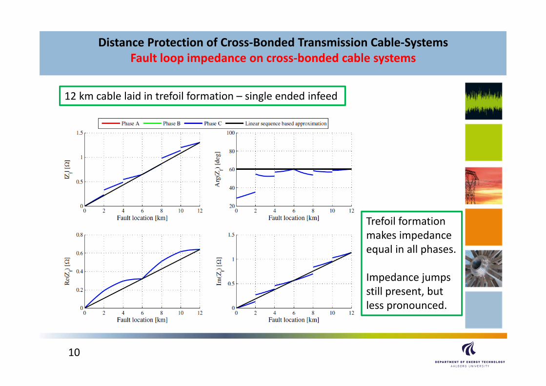
12 km cable laid in trefoil formation – single ended infeed
Trefoil formationmakes impedanceequal in all phases.
Impedance jumpsstill present, but less pronounced.
11
Distance Protection of Cross‐Bonded Transmission Cable‐SystemsFault loop impedance on cross‐bonded cable systems
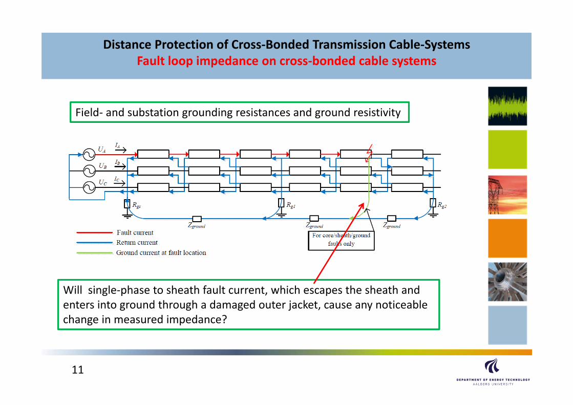
Field‐ and substation grounding resistances and ground resistivity
Will single‐phase to sheath fault current, which escapes the sheath and enters into ground through a damaged outer jacket, cause any noticeablechange in measured impedance?
12
Distance Protection of Cross‐Bonded Transmission Cable‐SystemsFault loop impedance on cross‐bonded cable systems
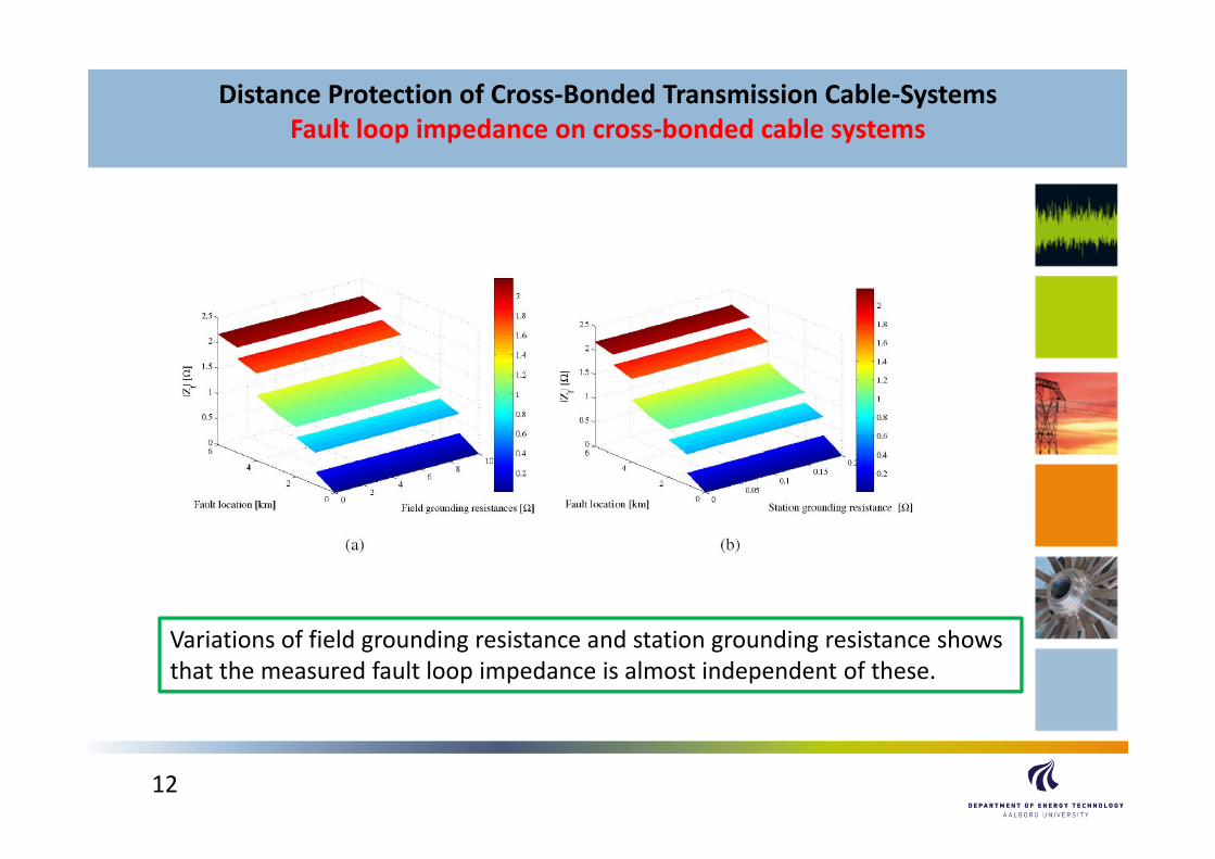
Variations of field grounding resistance and station grounding resistance showsthat the measured fault loop impedance is almost independent of these.

13
Distance Protection of Cross‐Bonded Transmission Cable‐SystemsFault loop impedance on cross‐bonded cable systems
Variations of the soil resistivity in the range 5 – 280 Ωm gives rise toa 2 % variation of the measured impedance.

14
Distance Protection of Cross‐Bonded Transmission Cable‐SystemsFault loop impedance on cross‐bonded cable systems
Core to sheath to ground faults
Fault current escapingto ground through adamaged outer jackethas no practical impor‐tance for fault loopmeasured impedance!
This is due to the factthat the screen currentpath has overall lowerimpedance than groundreturn.
15
Distance Protection of Cross‐Bonded Transmission Cable‐SystemsFault loop impedance on cross‐bonded cable systems
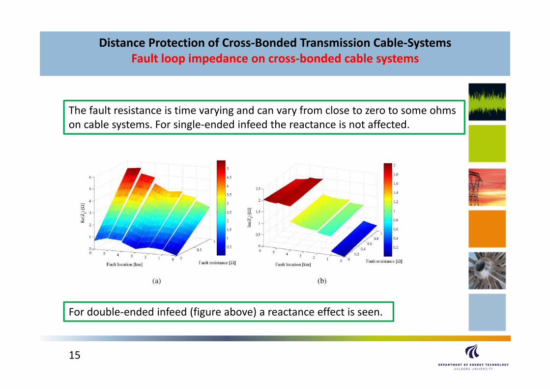
The fault resistance is time varying and can vary from close to zero to some ohmson cable systems. For single‐ended infeed the reactance is not affected.
For double‐ended infeed (figure above) a reactance effect is seen.

16
Distance Protection of Cross‐Bonded Transmission Cable‐SystemsFault loop impedance on cross‐bonded cable systems
Hybrid lines (OHL and cables in series)
When replacing the OHL’s over a longer period, cables and OHL’s exists at thesame time. In other words; when replacing one OHL between any two substationswith a cable, remaining OHL’s can still be connected to the two substations connecting to the new cable. Distance relays installed in the ends of the newcable will see the combined impedance of OHL and cable when using higher zonesfor back‐up.
When crossing locations of natural beauty with OHL’s, cables can be used as part of the entire line. In other words; OHL series impedance gets in series withcross‐bonded cable impedance along the line.
Cables are also put in series when an OHL is approaching urban areas or an offshorewind park is being connected.

17
Distance Protection of Cross‐Bonded Transmission Cable‐SystemsFault loop impedance on cross‐bonded cable systems
The Århus – Aalborg 420 kV line
The Mariager Fjord and the Gudenåare locations of natural beauty
18
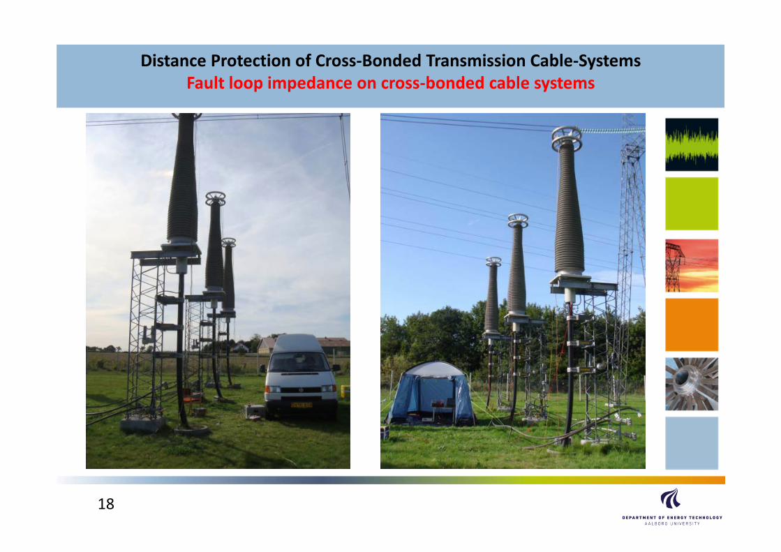
Distance Protection of Cross‐Bonded Transmission Cable‐SystemsFault loop impedance on cross‐bonded cable systems
19
Distance Protection of Cross‐Bonded Transmission Cable‐SystemsFault loop impedance on cross‐bonded cable systems
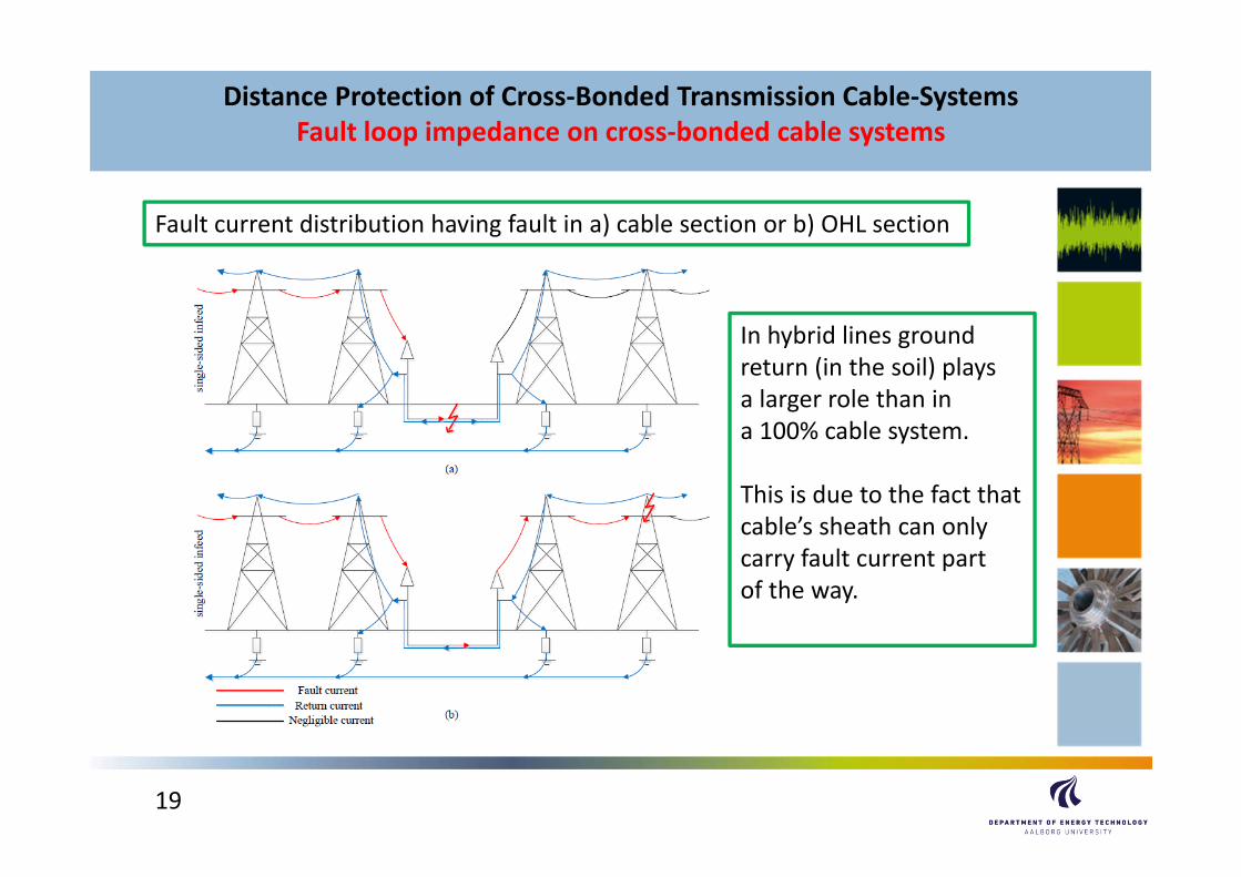
Fault current distribution having fault in a) cable section or b) OHL section
In hybrid lines groundreturn (in the soil) playsa larger role than in a 100% cable system.
This is due to the fact thatcable’s sheath can onlycarry fault current part of the way.
20
Distance Protection of Cross‐Bonded Transmission Cable‐SystemsFault loop impedance on cross‐bonded cable systems
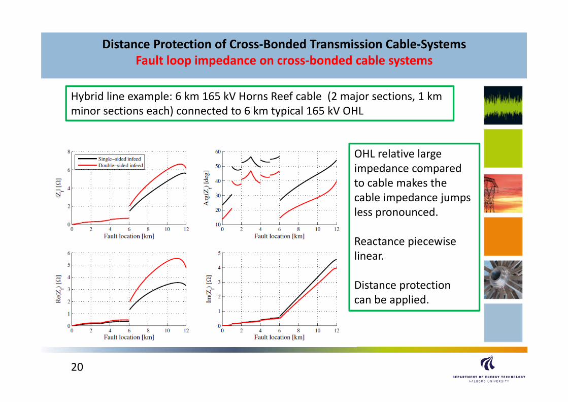
Hybrid line example: 6 km 165 kV Horns Reef cable (2 major sections, 1 km minor sections each) connected to 6 km typical 165 kV OHL
OHL relative largeimpedance comparedto cable makes the cable impedance jumpsless pronounced.
Reactance piecewiselinear.
Distance protectioncan be applied.
21
Distance Protection of Cross‐Bonded Transmission Cable‐SystemsDiscussion
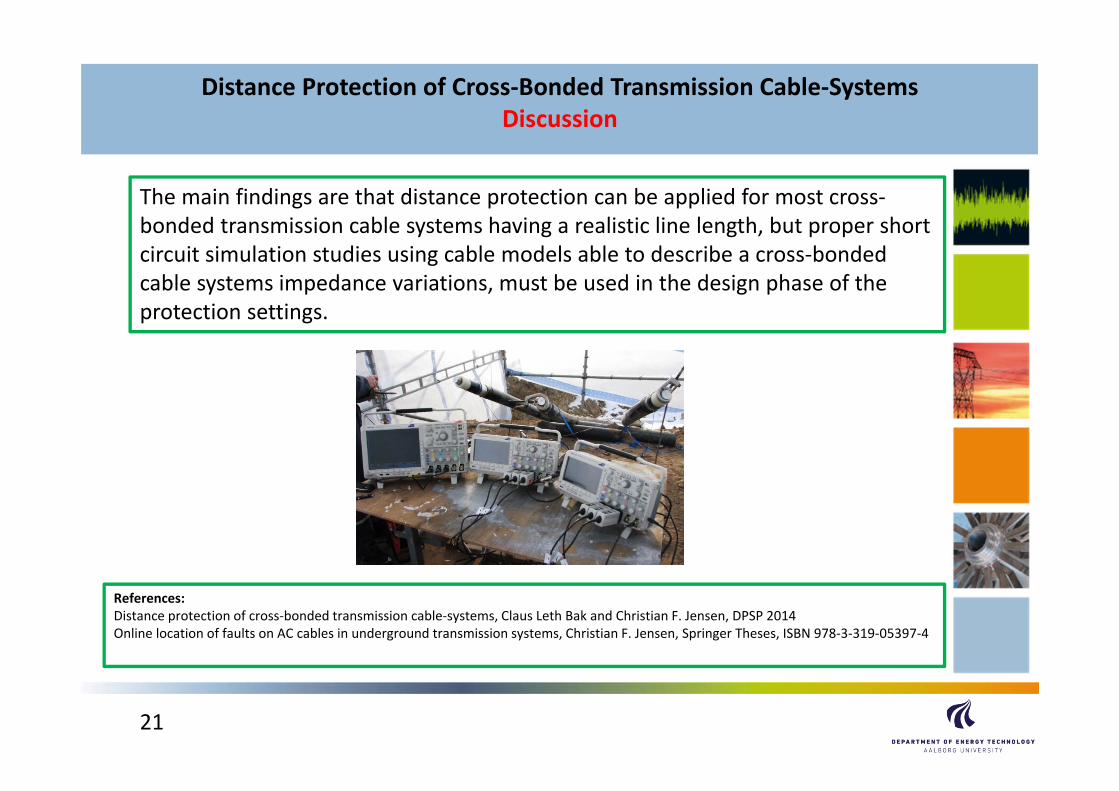
The main findings are that distance protection can be applied for most cross‐bonded transmission cable systems having a realistic line length, but proper short circuit simulation studies using cable models able to describe a cross‐bonded cable systems impedance variations, must be used in the design phase of the protection settings.
References:Distance protection of cross‐bonded transmission cable‐systems, Claus Leth Bak and Christian F. Jensen, DPSP 2014Online location of faults on AC cables in underground transmission systems, Christian F. Jensen, Springer Theses, ISBN 978‐3‐319‐05397‐4