distillation prepared by dr.nagwa el mansi chemical engineering department cairo university fourth...
TRANSCRIPT

DistillationPrepared by Dr.Nagwa El Mansi
Chemical Engineering DepartmentCairo University
Fourth year

References:-
1-Coluson and Richerdson, Chemical Engineering vol , vol II , vol III.
2- Geancoplis, Principles of Unit Operation.3- Mc-Cabe and Smith, Unit operations for Chemical
Engineering.4- Traybal, Mass Transfer Operations.5- Sherwood, Mass Transfer.6-Perry’s , Chemical Engineering.7- “Separation Process Principles”, 2nd ed, Seader et’al .8- Site on Google search, Separation Processes.

DistillationDistillation:-Is a method of separating homogenous mixturebased on differences in boiling points.Distillation is done by:-a-partial vaporization ( liq → vap)b-partial condensation (vap → liq)c- changing in pressure ( gas → liq)

Distillation has a number of applications:-1- It is used to separate crude oil into morefractions for specific uses such as transport,power generation and heating. 2-Water is distilled to remove impurities, such assalt from seawater.3- Air is distilled to separate its components oxygen, nitrogen, and argon for industrial use.
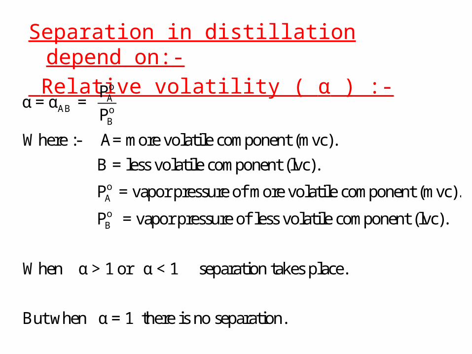
Separation in distillation depend on:- Relative volatility ( α ) :-
oA
AB oB
oA
Pα = α =
P
Where :- A= more volatile component (mvc).
B = less volatile component (lvc).
P = vapor pressure of more volatile component (mvc).
oB P = vapor pressure of less volatile component (lvc).
When α > 1 or α < 1 separation takes place.
But when α = 1 there is no separation.

Vapor-liquid Equilibrium:-[ When the liquid phase behaves as an ideal solution allmolecules have the same size; all intermolecular forces areequal; the properties of the mixture depend only on theproperties of the pure components of the mixture].
Phase Diagram (Binary Mixture)In our analysis of phase diagram, we shall consider only Twocomponent mixture, e.g. A (more volatile) and B (less volatile). There are 2 types of phase diagram: constant pressure or constant temperature.
Constant Pressure Phase Diagram Figure(1) shows a constant pressure phase diagram for an idealsolution (one that obey ) Raoult's Law


A typical equilibrium curvefor a binary mixture on x-ydiagram. It contains lessinformation than the phasediagram (i.e. temperature isnot included), but it is mostcommonly used. It is usefulfor graphical design indetermining the number oftheoretical stages requiredfor a distillation column.
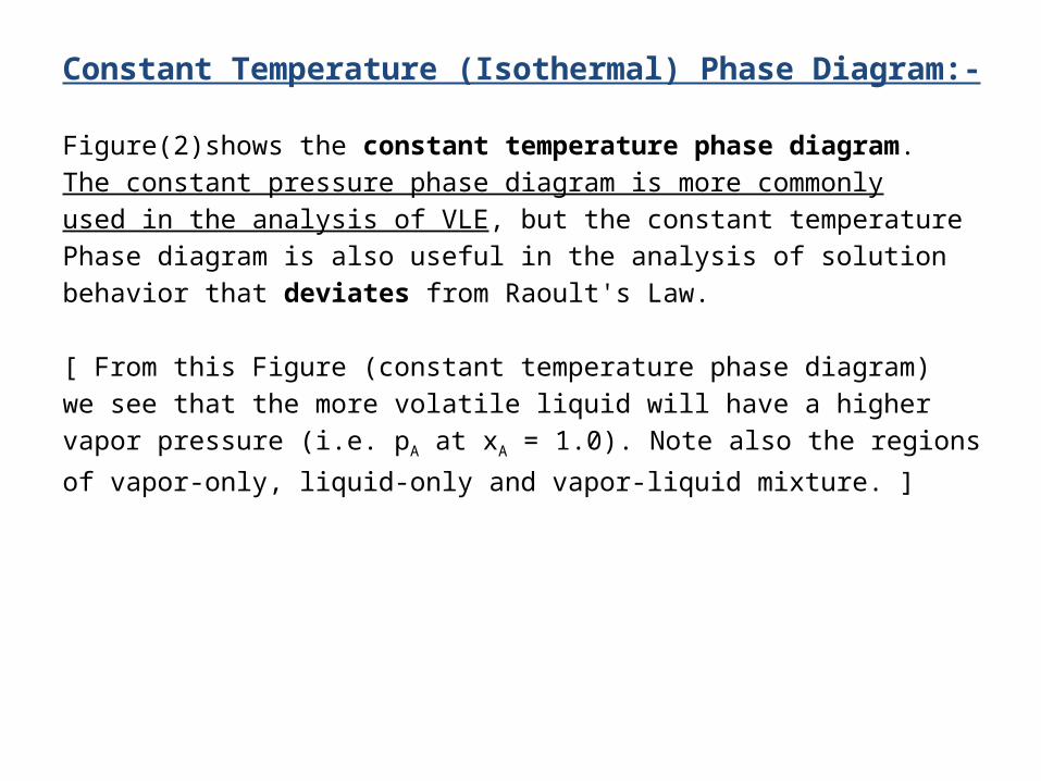
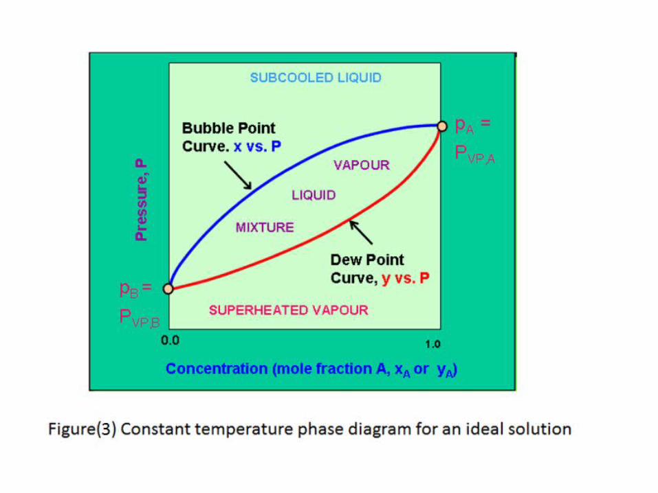
Constant Temperature (Isothermal) Phase Diagram:-
Figure(2)shows the constant temperature phase diagram.The constant pressure phase diagram is more commonlyused in the analysis of VLE, but the constant temperaturePhase diagram is also useful in the analysis of solutionbehavior that deviates from Raoult's Law.
[ From this Figure (constant temperature phase diagram)we see that the more volatile liquid will have a highervapor pressure (i.e. pA at xA = 1.0). Note also the regions
of vapor-only, liquid-only and vapor-liquid mixture. ]

Effects of Increased Pressures:- Although most distillations are carried out atatmospheric or near atmospheric pressure, it is notuncommon to distill at other pressures. High pressuredistillation (typically 3 - 20 atm). At elevated pressures,the vapor phase deviates from ideal gas behavior, andmodifications to the VLE data is required. After pressureP3, the critical pressure of the more volatile component is exceeded, and there is no longer a distinction betweenvapor and liquid. Distillation is no longer possiblebeyond this point. The majority of distillations arecarried out at pressures below 70% of the criticalpressure.


Abnormal mixtures:-1- Azeotropic Mixture:-Very large deviations from ideality lead to a special class of mixtures known as azeotropes , azeotropicmixtures, or constant-boiling mixtures. Azeotrope isa special class of liquid mixture that boils at a constanttemperature at a certain composition. At this condition,it behaves as if it was one component with oneconstant boiling point. A boiling liquid mixture at theazeotropic composition produces a vapor of exactly thesame composition, and the Liquid does not change itscomposition as it evaporates.

Two types of azeotropes are known:- minimum boiling and Maximum boilinga- Minimum-boiling azeotropes:a- One of the best known minimum-boiling azeotrope is theethanol-water system which at 1 atm occurs at 89.4 mole%ethanol and 78.2 oC.b- carbon-disulfide - acetone (61.0 mole% CS2, 39.25 oC, 1 atm)c- benzene - water (29.6 mole% H2O, 69.25 oC, 1 atm)b-Maximum-boiling azeotropes:- a-Hydrochloric acid - water (11.1 mole% HCl, 110 oC, 1 atm)b-Acetone - chloroform (65.5 mole% chloroform, 64.5 oC, 1 atm)

a-Minimum Azeotrope:-Figure(5) show the constant pressurephase diagram plus equilibrium curvefor a minimum-boiling azeotropicmixture of carbon disulfide (CS2) andacetone. At point L, the concentration inthe vapor phase is the same as theconcentration in the liquid phase ( y = x ),and a = 1.0. This concentration is known as the azeotropic composition (0.61 molefraction CS2). At this point , the mixtureboils at a constant temperature (39.25oC under 1 atm) and without change incomposition. On the equilibrium diagram, it can be seen that at this point,the equilibrium curve crossed the diagonal

b-Maximum boiling Azeotrope:-The Figure(6) shows the constantpressure phase diagram plusequilibrium curve for a maximumboiling azeotrope mixture ofacetone and chloroform. TheAzeotropic composition is 0.345mole fraction acetone.Point L in the Figures is now aminimum on the constanttemperature phase diagram, and amaximum (64.5 oC, under 1 atm)on the constant pressure phasediagram

2- Partial liquid miscbility:-Some substances exhibit suchlarge deviations from idealitythat they do not dissolvecompletely in liquid state, e.g.,Isobutanol-water

3-Complete immisciblity Mixtures:-The mutual solubility of someLiquids is so small that they can beConsidered substantially insoluble(Figure(8)) e.g., hydrocarbon andwater. The vapor pressure of eithercomponent cannot be influenced bythe other and each one exerts itsvapor pressure at the prevailingtemperature. When the sum of theseparate vapor pressures equals thetotal pressure, the mixture boils at atemperature lower than the boilingpoint of each component:-PA + PB = PT , or P◦A + P◦B = PT

Calculation of Vapor/Liquid Equilibrium:-1- By experimental methods:- (under certain P&T to gety = f(x)).2-Published data.3-Prediction of K values.
For binary mixture:- o
i i i
T i
oi
i i i iT
P = P . x ------ (Raoult's law)
P . y ------- ( Dalton's law)
P y = x = K x
P

i
oi
oi
iT
i i
where P :- partial pressure of component i
P :- vapor pressure of component i
P K = K-value for component i
P
x , y :- mole fractions of liquid and vapor respe
oT i i i
T A B
o oT A A B B
o oT A A A B A B
o o oT A A B B A
ctively
P = P = P . x
For binary mixture ( A & B ):-
P = P + P
P = P . x + P . x
P = P . x + (1- x ) P , where x + x = 1
P = P . x + P - P . x

o oT B A
A A Ao oA B T
oA A A A A A AoB B B A A A
P - P P x = and y = x ----(equilibrium relation)
P - P P
Also, another form of equilibrium relation by using relative volatility( )
P y /x y /x y (1-x ) α = = = =
P y /x (1-y )/(1-x ) x (1-y
A
A A A A A A
A A A A
A A A
AA
A
)
α x - αx y = y - y x
α x = (αx - x +1) y
α x = [(α - 1) x +1] y
α x y = ------ (equilibrium relation)
[(α - 1) x +1]

oi
i i i iT
oi
i i i iT
For multi-component system:-
For ideal system:-
P y = k . x = x
P
For non-ideal system:-
Py = k . . x = . . x
P
is the activation coefficient = measure of non-ideality
i i
iwhere

One Stage Distillation
1-Simple (differential) distillation (ASTM):- We will consider a binary mixture of A (more volatile)and B (less volatile). The set-up is as shown in theFigure(9) . The system consist of a batch of liquid feed (F)(fixed quantity) with a composition( xF) inside a kettle (or
still) fitted with heating element or steam jacket, and acondenser to condense the vapor produced. The condensedVapor is known as the distillate (D) with a composition (yD) .
The distillate is collected In a condensate receiver. Theliquid remaining in the still is known as the residual (W)With a composition ( xW).


At any time t, the amount of liquid in the still is L , with mole fraction of A in the liquid being (x). After a small differential time (t + dt) , a small amount of vapor dL is produced, and the composition of A in the vapor is (y) (mole fraction). The vapor is assumed to be in equilibrium with the residue liquid . The amount of liquid in the still is thus reduced from L to (L - dL), while the liquid composition changed from x to (x - dx). See the followingFigure (10):-
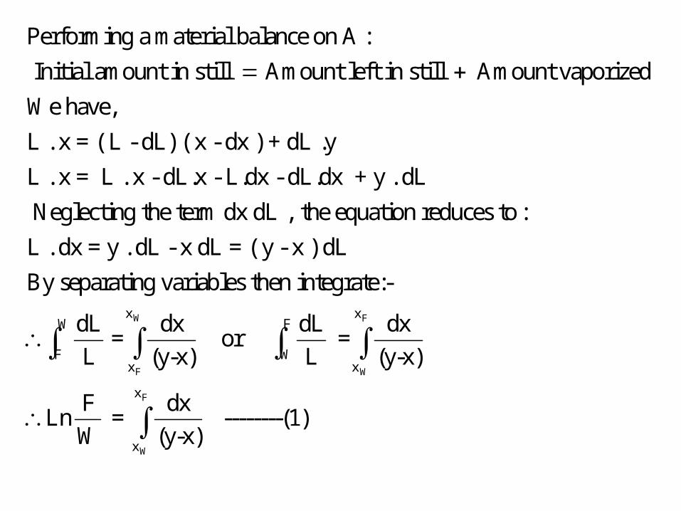
Performing a material balance on A :
Initial amount in still Amount left in still Amount vaporized
We have,
L . x = ( L - dL) ( x - dx ) + dL .y
L . x = L . x - dL.x - L.dx - dL.dx + y . dL
Neglect
W F
F W
F
W
x xW F
F Wx x
x
x
ing the term dx dL , the equation reduces to :
L . dx = y . dL - x dL = ( y - x ) dL
By separating variables then integrate:-
dL dx dL dx = or =
L (y-x) L (y-x)
F dxLn = ---
W (y-x)
-----(1)
F
W
F
W
x
x
x
x
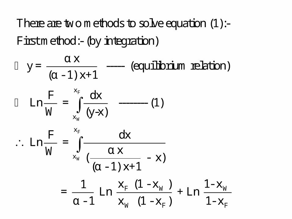
There are two methods to solve equation (1):-
First method:- (by integration)
α xy = ----- (equilibrium relation)
(α - 1) x+1
F dx Ln = -------- (1)
W (y-x)
F dx Ln =
α xW ( - x)(α - 1) x+1
F W W
W F F
x (1 - x ) 1- x1 = Ln + Ln
α - 1 x (1 - x ) 1- x

F
W
x
x
W
Second method :- (graphical integration)
F dx Ln = -------- (1)
W (y-x)
F Ln = Area under the curve (note x is unknown)
W
After performing the integration assume xw,(usually xw unknown) .If left hand side=right hand side your assumptionis correct if not repeat your assumption.


Steps for calculation the correct xw:-1-plot x-y diagram.2- assume xw.3-costruct the previous table between x and1/(y*- x).4 - plot x vs 1/(y*- x) as shown in the last figure.5- calculate the area under the curve = Ln F/W.6- if area = Ln F/W , your assumption of xw is correctif not reassume xw.7- finally calculate the correct xw.

Equation(1) can be used todetermine (xw) if (F, xF , D)
are known.Also the average distillatecomposition can beCalculated ( yD ) by simple
material balance:-F = D + W --------(2)F xF = D yD + W xW -------(3)
By solving the threeequations all the quantitiesand compositions can becalculated.

2-Flash (equilibrium) distillation:-A single-stage continuous operation where a liquid mixture is
partially vaporized, then flows through a pressure reducing valveto the separator. In the separator, separation between the vapor

and liquid takes place. How much of A is produced in the vapor(and remained in the liquid) depends on the condition of theFeed, (see Figure(13)). Vapor amount (V) with composition (y), and a liquid amount (L)with composition (x) are produced. The two streams leaving the flash drum (y and x )are inequilibrium with each others.
Flash distillation is done by:-1-Flash vaporization (liquid →heating→throttling valve →Separation ). 2-Flash condensation ( vapor →cooling →separation ).3- Feed at high pressure → change to low pressure.Some times flash distillation is used as a method forchanging conditions of a mixture.
A single-stage flash operation can rarely produce therequired purity or fractional recoveries. An obvious butinefficient approach is to apply a series of flashseparators condensing part of the vapor and boiling partof the liquid products from successive stages. Its preferred to use systems with high relative volatility inflash distillation to obtain considerable separation .

Operating line equation for flash distillation:-For binary mixture(A &B)
F
F
F F
F F
F F
Overall Material Balance:-
F = L + V
Component Material Balance:-
F. x = L . x + V . y
( L + V ) x = L . x + V . y
L ( x - x) = V ( y - x )
(y - x ) (y - x ) L L = or - = --
V ( x - x) V ( x - x )
F F
-----(4) (operating line equation)
This line lies between two points (x,y) and (x , x )
Land has a slope ( - )
VFigure(14) shows it's the graphical representation.


Multi-flash distillation:-
i
i
i i
i
F i i
F i i
F i i F
i Fi
F i
i i i
F = L + V
Component Material Balance:-
F. x = L . x + V . y
( L + V ) x = L . x + V . y
L ( x - x ) = V ( y - x )
(y - x ) L = -------- (5)
V ( x - x )
Equilibrium relation is y = k . x
i
i i i
i Fi
F i i
or can be written as x = y / k
substitute in equation (5) :-
(y - x ) L =
V ( x - y / k )

i
i
i
i
i
F i i i Fi
F ii
i F
i
F
i
i F
L ( x - y / k ) = (y - x )
VL L
x (1+ ) = y (1 + )V V. k
L( 1+ )
V y x --------- (6)L
(1 + )V. k
L( 1+ )
V or x x ------- (7)L
( k + )V
L( 1+ )
Vwhere :- x x (
i
ii F
ii
L( 1+ )
V1 and , y x 1L L
k + ) (1 + )V V. k

i
oi
i iT
i F
i
i
Stepes for calculation of multi-component distillation:-
P1- Calculate k values for each component ( k )
P
at certain temperature.
2- Assume L/V.
L( 1+ )
V3- Calculate y x 1L
(1+ )V k
4- If y
i i
1 repeat your assumption of L/V .
If y 1 your assumption is correct then calculate x 1
( solution is by trial and error)

Temperature calculations inside flash drum:-
Figure(16) shows an enthalpy balance for continuousoperation. The material and enthalpy balance are:-
F
F L V
F = L + V
F. x = L . x + V. y
F . h + Q = L . h + V. H -----(8)

F
L L,A r L,B r mix
V v,A r A v,B r B
where :-
h = feed enthalpy
Q = enthalpy gained by the heater
h = x [cp (T-T )] + (1-x) [cp (T-T )] + H -----(9)
H = y[cp (T-T ) +λ ] + (1-y) [cp (T-T ) + λ ] -----(10)
T = operating temperature
r
L
V
mix
A B
inside the drum
T = reference temperature
cp = liquid heat capacity , energy/mol.degree
cp = vapor heat capacity , energy/mol.degree
H heat of mixing (neglected for ideal system)
λ , λ = latent hea
rts of vaporization at T , energy/mol

Steps for calculation T :-1- assume T.2- calculate Ki.3- assume L/V.4- calculate yi .5- check ∑ yi =1.6- calculate xi .7- check the enthalpy balance, if (LHS = RHS )→ your assumption is correct, if notreassume T .Usually, T is assumed between the bubble and the dewPoints of the mixture.

Calculations of dew point and bubble point:-A-Bubble point:-
i i i i F
i i Fi
Fi bubble i
o o oi A B
Fi FA FBT T T
oi
FiT
y = k . x (for the first bubble x = x )
y = 1 = k . x
given, x , P assume T and calculate k
P P P x = x + x 1
P P P
Pif x = 1 your assumption is c
P
orrect
if not repeat your assumption

B- Dew point :-
ii i Fi
i
ii
i
Fi dew i
A Bi o o
A B
T T
i
i
y x = (for the first liquid droplet x = x )
k
y = 1 =
k
given, x , P assume T and calculate k
y y = 1 = +
P P( ) ( )
P P
y if = 1 your assumption is corr
k
x
x
ect
if not repeat your assumption

Trials to calculate bubblepoint
Trials to calculate dewpoint

3- Steam distillation:-
It is a method for distilling organic compounds which are heatsensitive materials (contaminated by traces of non volatileimpurities).This process involves using bubbling steam (whichis completely insoluble with the organic compound) through aheated mixture of the raw material to give maximum contactbetween steam and the compound.

By Raoult's law, some of the target compound willvaporize (in accordance with its partial pressure)leavingImpurities and condensed steam in the still. The vapor mixture(carried by steam) is cooled and condensed, usually yielding alayer of organic compound(c) and a layer of water(w). The vapor pressure of each component (c&w) cannot beinfluenced by the presence of the other and each one exertsits vapor pressure at the Prevailing temperature.When the sum of the separate vapor pressures equal the totalpressure, the mixture boils at a lower temperature (lower thanboiling points of c & w). The use of steam reduces the partialpressure of feed components and thus permits therevaporization at temperature below there normal boiling point.

o WW W W
T
W
oW
o CC C C
T
C
oC
PP = P , y =
P
P = partial pressure of water
P = vapor pressure of water
Also for the component (c):-
PP = P , y =
P
P = partial pressure of water
P = vapor pressure of water
T W C P = P + P (at boiling)


At boiling:-
C C
W W
C C C T
W T C W T
C C C
T C W W
P moles of materials n = =
P moles of water n
P P y . P moles of (c) P P P y . P moles of (w)
P M moles of (c) × M mass of (c) × = P - P M moles of (w) × M mass of (w)
mass of (w) = mass of stea
b mix inital
m used as a carrier.
Total amount of steam used = Steam used for heating m cp (T -T )
+ Steam used as a carrier
+ Steam used for vaporization m

Advantage of steam distillation:-1-Distillation takes place under low temperature.2-Prevent decomposition of thermally sensitive
materials.3- Cheap and economic.4-Avalability of heating medium.

Fractional Distillation or Differential Counter-Current Vapor/ Liquid Operations (Multi-stage Distillation):-
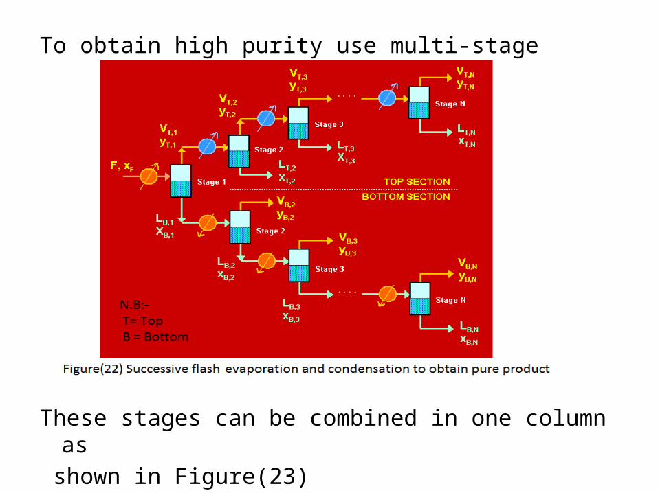
To obtain high purity use multi-stage arrangement
These stages can be combined in one column as shown in Figure(23)


Steam Distillation:- Steam distillation refers to a processin which live steam is in direct contactwith the distilling system. The basisof steam distillation rest on the factThat water forms immiscible mixtureswith most organic substances(mostcommonly employed in petroleumrefining operation) and these mixtureswill boil at a temperature below thatof either water or the other materials.Vaporization takes place at a temp.below its normal boiling point. Steam is widely used because of its energylevel, cheapness, and availability.


Total and partial condenser arrangements:-1-Total condenser:-In total condenser all saturated vapors at the top of thedistillation column condensed to saturated liquid
1 0
C 1 mix
C 0 mix
C 0mix
mix
y
Q = V λ
Q = ( L + D) λ
Q L = ( +1) λ
D D = ( R +1 ) λ
Dx x

C
1
1
D
Where:-
Q = condenser duty
V = vapor flow rate at the top plate in the distillation column
y = vapor composition at the top plate in the distillation column
D = distillate flow rate
x = distillate
0
0
0
composition leaving condenser
L = liquid flow rate returning back to the top plate
x = liquid composition returning back to the top plate
LR =
D = reflux ratio

2- Partial Condenser:-
Partial condenseracts as one platewith yD
in equilibrium withtop platecondensate x0
yD = KD x0
and yD = xD

Types of Reflux:-1- Cold Reflux:- Liquid stream returning back to theColumn is less than bubble point of the mixture.2- Hot Reflux:-Liquid stream returning back to theColumn is more than bubble point of the mixture.3- Recirculating Reflux or pumping around:-A side stream is withdrawn from the column to becooled and return back to the column.

Reboilers:-1- Internal Reboiler:-The tubular heat exchanger built into the bottom of thetower (Figure(33)) provides large surface area(no shell), but Cleaning requires a shut-downof the distillation operation.Liquid level is controlling for small capacity towers and for materials which aren’t corrosive and scaling.

2-External Reboilers:-A-Thermosiphon Reboiler:-The vertical thermosiphonreboiler as shown inFigure(34) with the heatingmedium outside the tubes,can be operated so as tovaporize all the liquidentering it to produce a vapor of the same composition as the residue product,in which no enrichment is provided.

B- Kettle Reboiler:- The kettle reboiler shown in Figure (35),with heating mediuminside the tubes,provides a vapor to thetower essentially inequilibrium with theresidue product andThus it behaves likea theoretical stage.It’s large in size , betterto control, long residencetime , not used for thermallysensitive materials

Pipe still heater:-Sometimes we use a Furnace or a pipestill heater insteadof the reboiler.Advantages:-1-Used when no steam is available(heating media ishot oil or hot gases).2- high temperatures is needed.Disadvantages:-1-Expensive.2- Not suitable for sensitive materials.

Distillation Calculations :-
F D W
F D W r
C
C
Overall Material balance (O.M):-
F = D + W
Component material balance(CMB):-
F x = D x + W x
Overall Heat Balance (OHB):-
F h + Q = D h + W h + Q
where:- Q = condenser duty
Q = V λ = V ( y1 mix 1
C
C
r
λ + (1-y ) λ ) 1 1 1 2
V = L + D1 0
Q =(L + D) λ = m cp ( T -T )0 mix water water water out water in
and Q = reboiler duty = m λ steam steam

Methods for calculation number of stages in distillation(1)Sorel plate to plate calculations:-
n+1 n
n+1 n+1 n n D
n+1 n+1 n n D
n+1 n+1 n n
For upper section:-
OMB
V = L + D ----(11)
CMB
V y = L x + D x --(12)
HB
V H = L h + D h Q ---(13)
Where:-
H = f (y ) and h = f (x )
C

m+1 m
m+1 m+1 m m w
m+1 m+1 r m m W
m+1 m+1
m m
For bottom section:-
OMB
L' = V' + W ---(14)
CMB
L' x' = V' y' + W x ---(15)
HB
L' h' + Q = V' H' + W h ----(16)
Where:-
h' = f (x' )
H' = f (y' )

Top or rectifying section ( total condenser conditions):-
Calculation steps :-1-Assume V2 then get L1 from
(OMB) equation.2- Calculate y2 after calculating
x1 ( from Eq.relation → y1 = k1 x1 )
3- If LHS = RHS (in HB equation) → yourassumption is correct if not repeat your assumption.
2 1
2 2 1 1 D
2 2 1 1 D
1 1 1
First plate ( n = 1 )
V = L + D ---(OMB)
V y = L x + D x ---(CMB)
V H = L h + D h Q ---(HB)
where:- y k x --- (Eq.relation)C

3 2
3 3 2 2 D
3 3 2 2 D
2 2 2
3 2
Second plate ( n = 2 )
V = L + D ---(OMB)
V y = L x + D x ---(CMB)
V H = L h + D h Q ---(HB)
where:- y k x --- (Eq.relation)
same previous steps for calculation V and L
then calculation of
C
3
n f n f
y , then checking your assumption
from heat balance equation.
Repeat your calculations till you reach
x = x or x x
then calculate the number of stages in the upper section
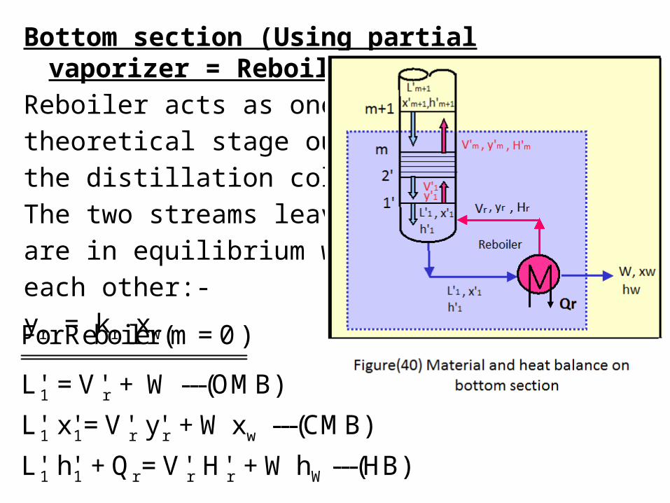
Bottom section (Using partial vaporizer = Reboiler ):-Reboiler acts as onetheoretical stage outsidethe distillation column. The two streams leaving it are in equilibrium witheach other:-yr = kr xw
1 r
1 1 r r w
1 1 r r r W
For Reboiler (m = 0 )
L' = V' + W ---(OMB)
L' x' = V' y' + W x ---(CMB)
L' h' + Q = V' H' + W h ---(HB)

Steps for calculations:-1-Assume Vr then get L’1 from(OMB) equation.
2- Calculate x’1 after calculating yr
( from Eq.relation → yr = kr xw )
3-Substituting by Vr , H’r , L’1 , h’1
in the (HB) equation. (after calculating the correct temperature inside the reboiler)4- If LHS = RHS → your assumption is correct if not repeatyour assumption.

2 1
2 2 1 1 w
2 2 r 1 1 W
2 2 2
First plate 1' from the bottom (m = 1 )
L' = V' + W ---(OMB)
L' x' = V' y' + W x ---(CMB)
L' h' + Q = V' H' + W h ---(HB)
Where : y' = k' x
Same steps were followed till the vapor compositi
on equal
or more than feed composition (y x ).
All the above depends on the reflux ratio, in which Q and Q
were calculated.
m F
C r

2- Ponchon Savarit method (Graphical representationof Sorel method ) :-
F D W
F r D W C
F D W C r
C rF D W
CD
F = D + W -----(OMB on the distillation column)
Fx = D x + W x -----(CMB)
F h + Q = D h + W h + Q ----(HB)
F h = D h + W h + Q - Q
Q Q F h = D (h + ) + W (h - )
D WQ
put Q' = ( h + D
rW
F
Q) & Q" = ( h - )
W F h = D Q' + W Q" ---------(17)
F D W
F D W F
W F
F D
F
F
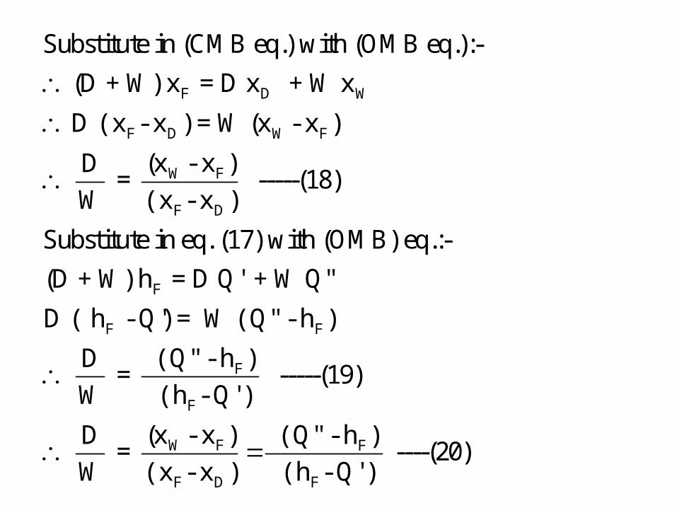
Substitute in (CMB eq.) with (OMB eq.):-
(D + W) x = D x + W x
D ( x - x ) = W (x - x )
(x - x )D = -----(18)
W ( x - x )
Substitute in eq. (17) with (OMB) eq.:-
(D + W) h = D Q' + W Q"
D ( h
F
F
F
W F F
F D F
- Q') = W ( Q" - h )
( Q" - h )D = -----(19)
W ( h - Q' )
(x - x ) ( Q" - h )D = ----(20)
W ( x - x ) ( h - Q' )

D F F W
n+1 n
n+1 n+1 n n D
n+1 n+
Equation 20 is an operating line equation for the hole column
between three points (x , Q' ) , ( x , h ) , ( x ,Q").
For top section:-
V = L + D ---(11)
V y = L x + D x ---(12)
V H
1 n n D C
Cn+1 n+1 n n D
n+1 n+1 n n
n n+1 n n D
n+1 D n n n+1
= L h + D h Q ---(13)
Q V H = L h + D ( h )
DV H = L h + D Q' -----(21)
By substituting eq.(11) in eq.(12)
(L + D) y = L x + D x
D ( y x ) = L ( x y )

n n+1
n n+1 D
n n+1 n n
n+1 n n n+1
n n+1
n n+1
n n+1
n
( x y )D = -----(22)
L ( y x )
By substituting eq.(11) in eq.(21)
( L + D) H L h + D Q'
D ( H Q' ) = L ( h H )
( h H )D = ------(23)
L (H Q' )
( x y )D =
L ( y
n n+1
n+1 D n+1
n n n+1 n+1 D
( h H ) = -----(24)
x ) (H Q' )
Equation 24 is an operating line equation for the top section
between three points (x , h ) , (y , H ) , (x , Q' ).

m+1 m
m+1 m+1 m m w
m+1 m+1 r m m W
rm+1 m+1 m m W
m+1 m+1 m m
For bottom section:-
L' = V' + W ---(14)
L' x' = V' y' + W x ---(15)
L' h' + Q = V' H' + W h ----(16)
QL' h' = V' H' + W ( h - )
W L' h' = V' H' + W Q" ----(25)
By su
m m+1 m m w
m+1 w m m m+1
m m+1
m m+1 w
bstituting eq.(14) in eq.(15)
(V' + W ) x' = V' y' + W x
W ( x' x ) = V' ( y' x' )
( y' x' )W -----(26)
V' ( x' x )

m m+1 m m
m+1 m m m+1
m m+1
m m+1
m m+1 m m+
m m+1 w
By substituting eq.(14) in eq.(25)
( V' + W) h' = V' H' + W Q"
W ( h' Q") = V' ( H' h' )
( H' h' )W -----(27)V' ( h' Q'')
( y' x' ) ( H' h'W V' ( x' x )
1
m+1
m m m+1 m+1 w
) ----(28)
( h' Q'')
Equation (28) is an operating line eq. for the bottom
between three points (y' , H' ) , ( x' , h' ), ( x , Q'')

Enthalpy-composition diagram:- (Ponchon-Savarit
Method )
1-Takes into account latent heats, heats of mixing &
sensible heats.
2-No assumption of molal flow rates.
3-Graphical procedure combining enthalpy & material
balances.
4- Provides information on condenser & reboiler duties.


The diagram at a given constant pressure is based onreference states of liquid and temperature such as 273K.Use enthalpy concentration data:-The data that require for enthalpy concentrationdiagram are:1-Heat capacity of the liquid, Cp
2-Boiling temperature, Tb
3-Latent heats of vaporization, λ4-Heat of solution, ∆Hmixing
The saturated liquid line in enthalpy h kJ/kg can beobtained from the following :-

The saturated vapor line can be obtained fromthe following equation below:-
x & y = mol or mass fractions of liquid & vapor. T= boiling point of temperatureTr = reference temperature
C p,L & C p,v = liquid & vapor heat capacity
∆Hmix = heat of solution at Tr ( neglected for ideal
system).
L L,A r L,B r mixh = x [cp (T-T )] + (1-x) [cp (T-T )] + H -----(9)
V v,A r A v,B r BH = y[cp (T-T ) +λ ] + (1-y) [cp (T-T ) + λ ] -----(10)

Again the difference in enthalpy between thestreams passing each other is constant, with theenthalpy of this stream being Q’ = hD + Qc / D ,
where Q c is the condenser duty in kJ/h.
C 1 0
0
C
C
C D
Also, Q V λ = ( L + D )
L = D ( + 1 ) = D ( R + 1)
D Q = D ( R + 1) λ
Q = ( R + 1 ) λ ------(29)
D
If R is assumed or given, calculate Q then Q' = ( h +
CQ )
Dwhich is the difference point ( or polar ) of the top section.

This difference Q’ is a common operating pointfor all values of yn+1 and xn in enriching section
of the distillation tower that having an enthalpy[Q’ = hD + Qc / D ] and a composition of xD . The
intersection of y1 is shown in the diagram having
the composition y1= xD for a total condenser. The
liquid x1 is in equilibrium with y1 and is located by
drawing a tie line through y1 intersecting the
saturated liquid line at x1. Next, a line is drawn as
x1Q’ , which is intersects saturated vapor line at y2.
following the operating line equation of the topSection (eq.(24)).


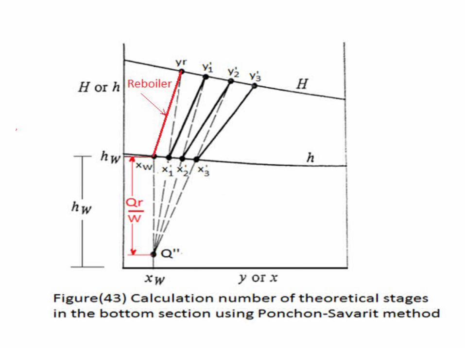
Also , the difference point (or polar) in the strippingsection is called Q”, having an enthalpy Q”= ( hw -Qr/W)and a composition xw . This point Q” is an operatingpoint just as Q’ for the enriching section. The point Q”is plotted below. Starting at point xw a tie line is drawn through this pointintersecting the saturated vapor line at yr, is inequilibrium with xw . Next, the line yr Q” is drawn,which intersects the saturated liquid line at x’1.
Hence, x’1 must be on the line between yr and Q”.
Next, the tie line x’1y’1 is drawn. This process is
continued in stepping off the theoretical plates.


Steps for calculation the theoretical number of stages:-1-Draw the enthalpy-concentration plot & the x-yequilibrium plot on the same graph.2-Determine the points xF , xD , xW.
3-Use the following equation to calculate Q’= hD + Qc / D.
4-Locate point Q’ at (xD , Q’)
5-Locate point y1 at (xD , H1)
6-Locate point x0 at (xD , hD) → for total condenser.
7- use the following equation to calculate Q” = hw - Qr/W.8-Draw the locus of Q” which is a vertical line from xw,{ point Q” at (xw , Q”)}.

9-Draw the line from Q’ to intersect hF (enthalpy of
saturated liquid at xF and the vertical line of xW). The
point of intersection shows Q” .10-From point y1, draw a line down to 45o line. Then,
draw a horizontal tie line to cut the x-y equilibriumcurve. Draw a line up to the liquid enthalpy curve. Thispoint is x1.
11-Plot an operating line from x1 to Q’, intersecting the
vapor enthalpy curve at y2. From y2, draw a vertical line
down to the equilibrium curve. Draw yet another line,go up to obtain x2; repeat the process until you exceed xF

12- Also, from point xw draw a tie line connectingBetween xw & yr. 11-Draw an operating line from Q”yr to intersect theliquid enthalpy curve at x’1 .
12-To obtain y’2 repeat the process until you exceed xF
13-The tie lines drawn between x1 to y1, x2 to y2, x3 to y3
and so on = number of stages.

Minimum reflux ratio:-Determine Q’min from the graph.
-From point, (xF ,hF), draw a line down to equilibrium
curve. Then, draw a horizontal line to 45o line. Next,draw a line up to saturated vapor line. Let say the pointis y.-Then, draw a line from point (xF ,hF) to point y till you
reach the vertical line of xD.- Q’min is the point intersect between the line from
point (xF ,hF) to point y and vertical line of xD .


3-Lewis plate to plate calculations:-Lewis assumes that:-1- If the amount of molecules which evaporate andwhich condensate are the same. This means that withineach section the liquid and the vapor flow rates remainconstant in the whole section.This can be translated into the following equations:For Top or Rectifying Section:-L1 = L2 = L3 = ......... = Ln = constant
V1 = V2 = V3 = ......... = Vn = constant
For Bottom or Stripping Section:-L’1 = L’2 = L’3 = ......... = L’m+1 = constant
V’1 = V’2 = V’3 = ......... = V’m = constant

2- The heat of vaporization (λ) of the two componentsof the feeding mixture must be the same ( λmvc = λLvc ) .
3- There is no losses from the column.4-No heat of mixing ∆ H mix = 0 (Ideal system).
{ In this case the saturated liquid and vapor curvesbecomes two straight parallel lines in the enthalpycomposition diagram}.
Based on the assumptions made and the identifieddata and unknows, we can rewrite the mass balancesand equilibrium equations for both the sections asFollows:-

n+1 n
n+1 n+1 n n D
n+1 n D
n+1 n
For upper section:-
V = L + D ----(OMB eq.)
V = L + D -----(OMB eq. in Lewis method)
V y = L x + D x ----(CMB eq.)
V y = L x + D x ----(CMB eq. in Lewis method)
L y = x +
V
D
D x -----( 30)
V

Equation (30) or (31) are operating line equationshaving slop L/V or R/R+1 and there intersection with y-axis are D/V or xD/ R+1 .
n+1 n D
n+1 n D
n+1 n D
Also,
L D V = L + D y = x + x
L + D L + D L/D D/D
y = x + xL/D + D/D L/D + D/D R 1
y = x + x -----( 31)R+1 R+1

Equation (32) is an operating line equation has a slope L’/V’ and intersection with y-axis is- Wxw/V’ .
m+1 m
m+1 m+1 m m w
m+1 m w
m
For bottom section:-
L' = V' + W ---(OMB eq.)
L' = V' + W -----(OMB eq. in Lewis method)
CMB
L' x' = V' y' + W x ---(CMB eq.)
L' x' = V' y' + W x ---(CMB eq.in Lewis method )
y' =
m+1 w
L' Wx' - x -----(32)
V' V'
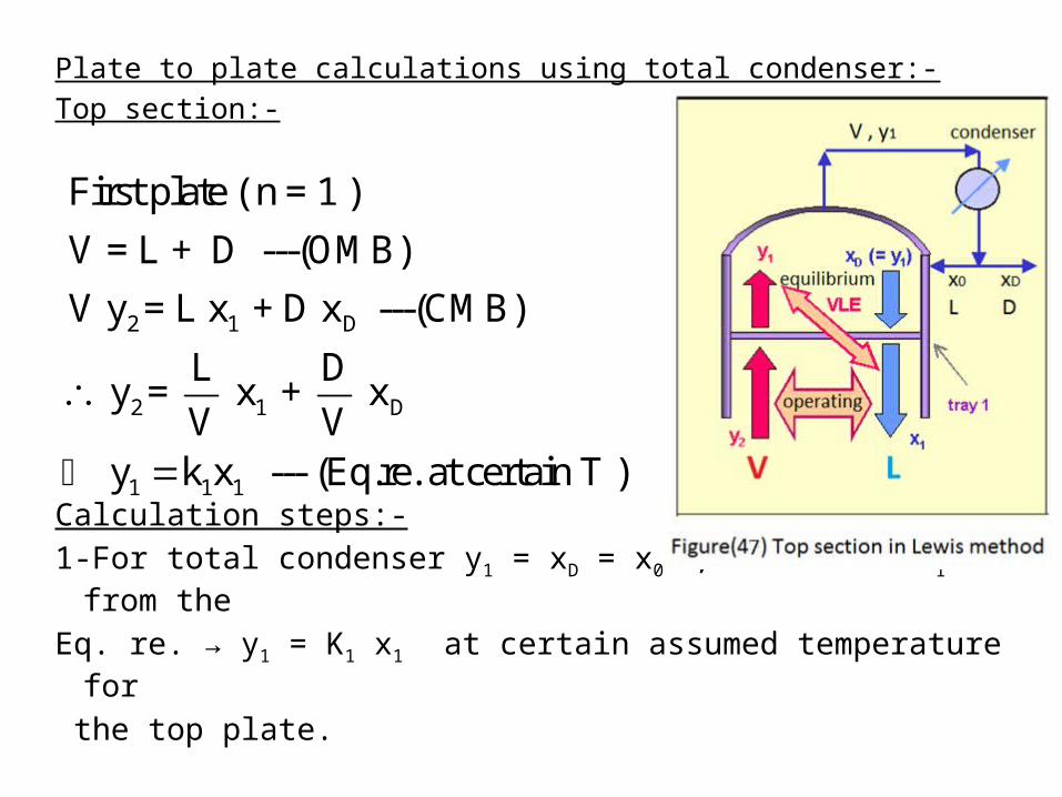
Plate to plate calculations using total condenser:-Top section:-
Calculation steps:-1-For total condenser y1 = xD = x0 , calculate x1 from the
Eq. re. → y1 = K1 x1 at certain assumed temperature for
the top plate.
2 1 D
2 1 D
1 1 1
First plate ( n = 1 )
V = L + D ---(OMB)
V y = L x + D x ---(CMB)
L D y = x + x
V V y k x --- (Eq.re. at certain T )

2-Substitute in equation (30) or (31) then calculate y2
(notice that the trails only on temperature not on theamount as in Sorel method).3-After calculating the correct y2 , calculate y3 from:-
4- Continue your calculation and so on till you reach
xn ≤ xF .
3 2 D 3 3 3
n = 2
L D y = x + x & y = k x
V V
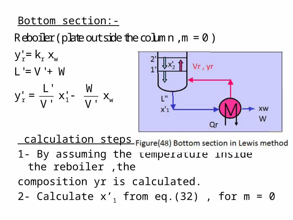
Bottom section:-
calculation steps:-1- By assuming the temperature inside the reboiler ,thecomposition yr is calculated.2- Calculate x’1 from eq.(32) , for m = 0
r r w
r 1 w
Reboiler ( plate out side the column , m = 0 )
y' = k x
L' = V' + W
L' Wy' = x' x
V' V'

3- calculate y’1 from the equilibrium relation, then
calculate x’2
4- Continue your calculation and so on till you reach y’m ≥ xF .
1 1 1
1 2 w
First plate inside the column , m =1
y' = k x
L' Wy' = x' x
V' V'

4- Mc-Cabe Thiele Method (graphical representation ofLewis method):-To obtain the number of theoretical trays using theMcCabe-Thiele method,we shall divide the columninto 3 sections: rectifying, feed and stripping sections.As these sections are thenrepresented on the (x-y)equilibrium curve for thebinary mixture in question and re-combined to make a complete design, as shown in Figure (49).

1- Top section:-
n+1 n D
n+1 n D
D
V = L + D ---(OMB)
V y = L x + D x ---(CMB)
( L + D ) y = L x + D x
The point of intersection between this operating line equation
and 45 line (x = y) is:-
( L + D ) y = L y + D x
L y + D
D
D
D D
y = L y + D x
D y D x y = x = x
the point of intersection between top operating line
and 45 line is (x , x )
D

The top operating line is drawn from its upper end at y1 = x0
= xD (on the 45o line), with a slope L/V = R/R+1
and anintercept =(xD /R+1)
with y-axis constant for given R andpurity ofdistillate xD .

2- Bottom section:-
1 w
m m+1 w
V' = L' - W ---(OMB)
V' y' = L' x' + W x ---(CMB)
( L' W ) y' = L' x' + W x
The point of intersection between this operating line equation
and 45 line (x = y) is:-
( L' W ) y' = L' y'
m m
w
w
w w
w w
W x
L' y' W y' = L' y' W x
W y' = W x y' = x' = x
the point of intersection between top operating line
and 45 line is (x ,x )

The bottom operating line is drawn from its lower endat (xw
, xw )
(on the 45o line)with a slope L’/V’ and an intercept = - W xw/ V’with y-axis .

3-Feed stage consideration:-By solving the two operatingline equations (top andBottom) at the pointof intersection (xi , yi)
i i D
i i w
i i D W
i i F
i i F
( V y = L x + D x ) (Top)
+ (V' y = L' x W x ) (Bottom)
(V' V) y = (L' L) x (D x +Wx )
(V' V) y = (L' L) x F x
(V' V) (L' L)y = x x ----(33)
F F

q- line definition:-
i
Material balance on feed entrance:-
F + L + V' = V + L'
F + ( V' V) = ( L' L)
( V' V) ( L' L)1 + = = q
F F( L' L) ( V' V)
q & q 1 = F F
By substitution in equation (33) with these values:-
q y =
Fi x -----(34)
q 1 q 1
qIt is the q line equation , it's slope
q 1
x
F L V V L
L L V V
F V L
F V L
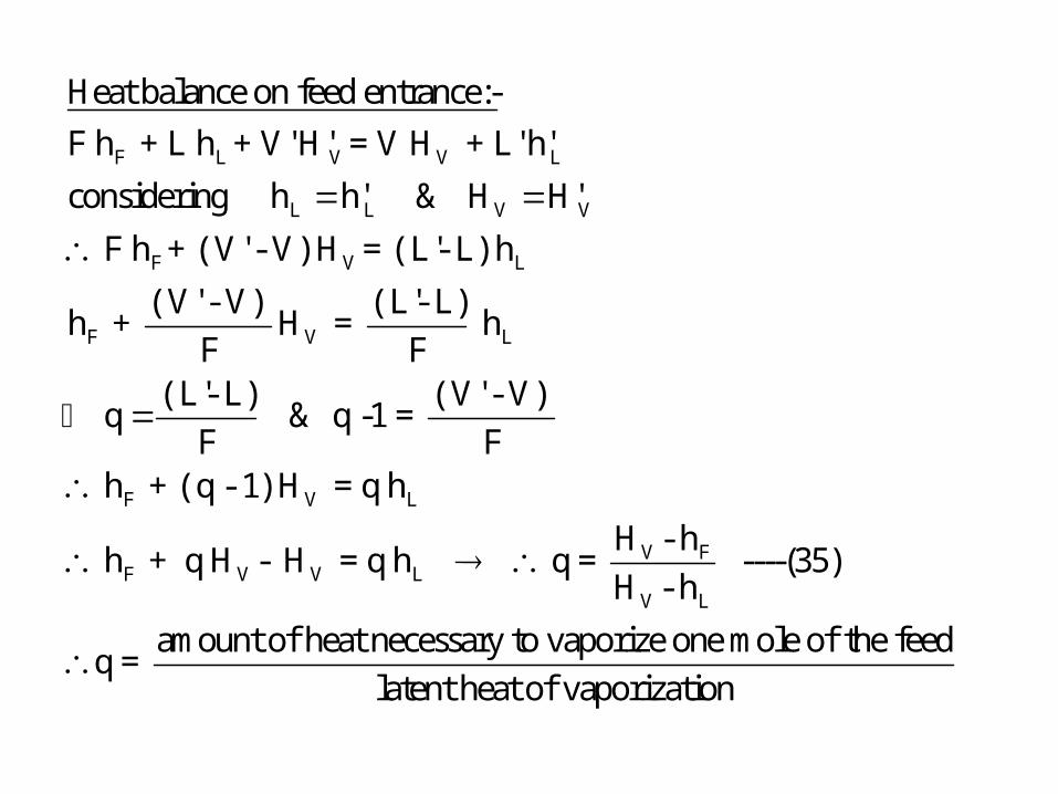
Heat balance on feed entrance:-
F h + L h + V' H' = V H + L' h'
considering h h' & H H'
F h + ( V' - V) H = ( L'- L) h
( V' - V) ( L'- L)h + H = h
F F( L'- L) ( V' -
q & q -1 = F
F V L
V FF V V L
V L
V)
F h + ( q - 1) H = q h
H - h h + q H - H = q h q = ----(35)
H - h
amount of heat necessary to vaporize one mole of the feedq =
latent heat of vaporization

For different feed conditions, q has the followingnumerical limits :-
F L
V F
V L
V L
V L
1 Saturated liquid feed:-
h = h
H h q =
H h
H h q = = = 1
H h
q line:-
q 1
q 1 1 1
q-line is a vertical line
L V
F
bubble point liquid feed

F V
V V
V L
V V
V L
2 Saturated vapor feed:-
h = h
H h q =
H h
H h q = = 0
H h
q line:-
q 00
q 1 0 1
q-line is a horizontal line
L V
F
dew point vapour feed

3 Partial vaporized feed:-
0 < q < 1
e.g q = 0.7
q line:-
q 0.7 0.7 = ve
q 1 0.7 1 0.3
q-line has a -ve slope
L V
F
partially vaporized feed

F V
V V
V L
4 Subcooled feed:-
h < h
H h q =
H h
m cp ΔT + λ = > 1
λq line:- ( assume q = 1.5 )
q 1.5 +ve
q 1 1.5 1 +ve
line in the first quarter
L V
F
subcooled liquid feed

F V
V
V L
5 Superheated feed:-
h > H
H h veq = = = ve
H h +ve
q line:-
q
q 1 1 ve
q-line in the third quarter
F
ve ve
ve
L V
superheated vapour feed
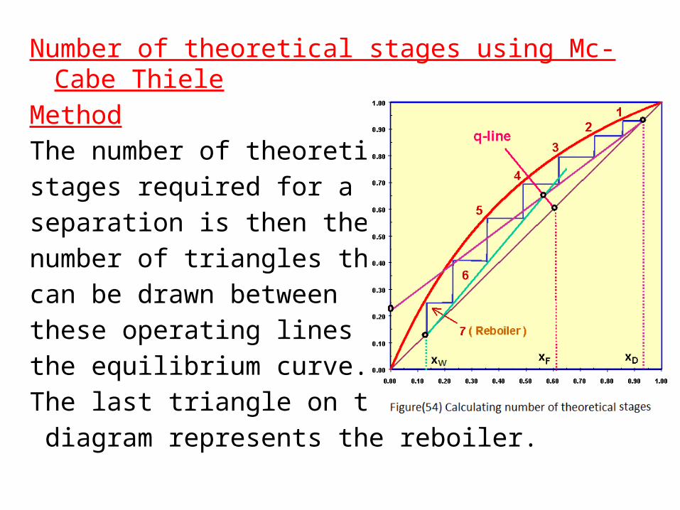
Number of theoretical stages using Mc-Cabe ThieleMethodThe number of theoreticalstages required for a givenseparation is then thenumber of triangles thatcan be drawn betweenthese operating lines andthe equilibrium curve. The last triangle on the diagram represents the reboiler.

Some cases in Mc-Cabe Thiele method:-(1) Calculation of no. of stages in complex feed( morethan one feed):-
11
1 1
11
For first feed:-
L' Lq get L' assume sat.liq.
F
LV = L + D get R =
DD is calculated from (OMB)
calculate L & V .
q known , F known
caculate L'.
V' V q 1 get V'
F

Draw operating line for topSection, the draw operating Line for bottom section, thenconnect between the twoLines as shown in the opposite figure.
22
22
For second feed:-
L" Lq get L"
F
assume vap.liq.
V" V q 1 get V"
F

If the two feeds were mixed together the introduced to The column, how many stages would be required toperform this separation.
1 2
F 1 F1 2 F2
mix 1 1 2 2
By mixing:-
F = F + F
F x = F x + F x
F q = F q + F q
No. of stages in second
case > No. of stages in
the first case.
It's prefered to introduce each feed
at it's corresponding composition
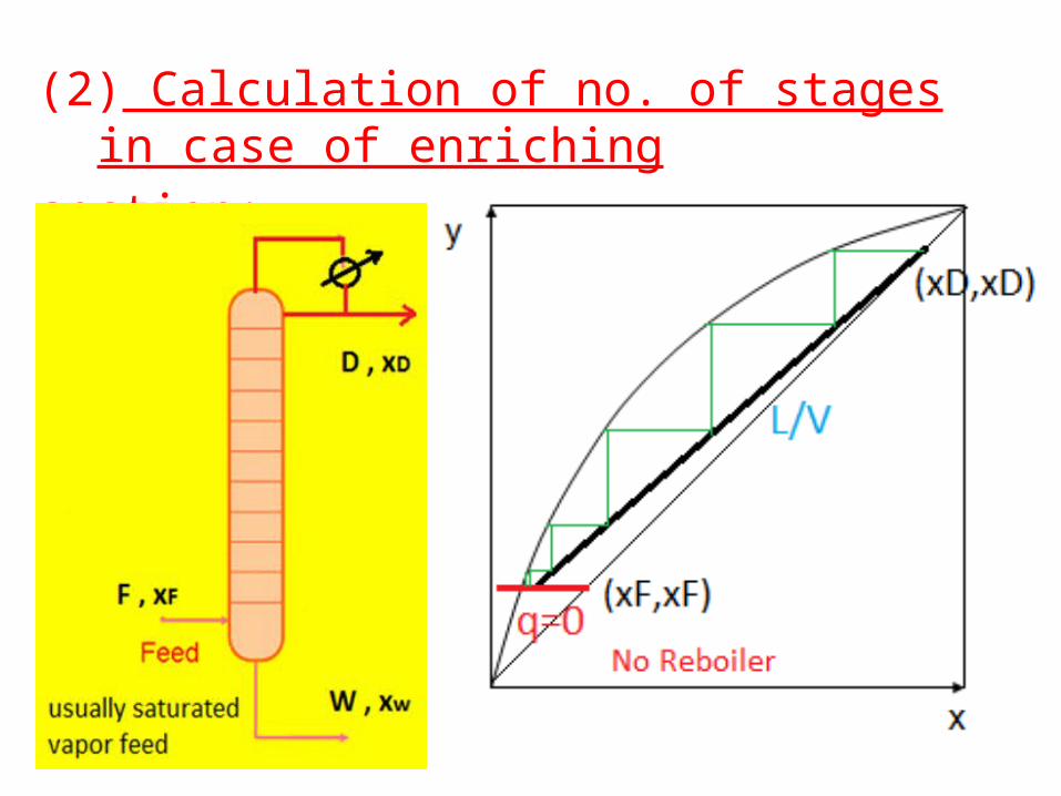
(2) Calculation of no. of stages in case of enrichingsection:-

(3) Calculation of no. of stages in case of strippingsection:-
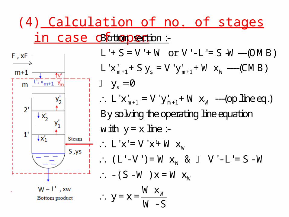
(4) Calculation of no. of stages in case of opensteam:-
m+1 s m+1 W
s
m+1 m+1 W
Bottom section :-
L' + S = V' + W or V' - L' = S -W---(OMB)
L' x' + S y = V' y' + W x ----(CMB)
y 0
L' x' = V' y' + W x ---(op.line eq.)
By solving the operating line equation
with y = x
W
W
W
W
line :-
L' x' = V' x'+ W x
( L' - V' ) = W x & V' - L' = S - W
- ( S - W ) x = W x
W x y = x =
W - S

Open steam presentation in Mc-Cabe Thiele method
Open steam presentation in Ponchon Savarit method

(5) Calculation of no. of stages in case of sidesteam:-In some applications, a product other than top orBottom side products are also withdrawn fromthe column, which is usually a saturated liquidproduct . Assume the flow rate of intermediateproduct is S with composition xs. The column is divided into three sections:- top , middle andbottom.

Material balance on the top Section:-
n+1 n S D
S D
S D
V = L + S + D ---(OMB)
( V - L ) ( S + D )
V y = L x + S x + D x (CMB)
The point of intersection between this
operating line and 45 line
V y = L y + S x + D x
( V - L ) y = S x + D x
y =
S D S DS x + D x S x + D xx =
( V - L ) ( S + D )


Material balance on the bottom section:-
m+1 m S w
S w
L' = V' + S + W ---(OMB)
( L' - V' ) = ( S + W )
L' x' = V' y' + S x + W x (CMB)
The point of intersection between this
operating line and 45 line
L' y = V' y + S x + W x
( L' - V' ) y = S x
S w
S w S w
+ W x
S x + W x S x + W x y = x = =
( L' - V' ) ( S + W )


Packed tower for small capacities:-

Comparison between Mc-Cabe Thiele methodand Ponchon-Savarit method Mc-Cabe Thiele method Ponchon-Savarit method
1- Simple 1- Complex
2-Require (x-y )diagram only
2-Require enthalpy comp.Diagram & (x-y )diagram
3-Less data Much more data
4-Equi-molar flow rates 4-Require more data on each section( M.B, H.B , Eq.re.,…)

Operating conditions:-(1) Reflux ratio , R :-As R decreases, separation becomes difficult, drivingforce(D.F) decreases, number of stages increase theoperating line for the rectification section movestowards the equilibrium line. The ‘pinch’ between operating andequilibrium lines becomes more pronounced and more and more trays are required. In this caseR = Rmin and the number of stages
reaches infinite ( N=∞)→ Pinch point, and D.F = zero.

As R increases, separation is improved, D.F increases,the two operating lines goes down till they coincide
With 45◦ line and L/V =1. At this condition R= ∞ = totalreflux and number of stages is minimum.

Relation between number of stages and reflux ratio:The minimum reflux ratio and the infinite reflux ratioplace a constraint on the range of separation operation. Any reflux ratio betweenRmin and Total R will
produce the desired separation, with the corresponding number of theoretical stages varying from infinity at Rmin to the minimum number (Nmin at Total R).

Optimum reflux ratio:-A trade off between operating cost and equipment costis needed.As R increases →less stages ,less equipment cost is needed. As R decreases →more stages ,more equipment cost isneeded, more boiling andcondensation.Equipment and operating costsCombine to give total cost( Ropt = 1.1 to 1.5 Rmin)

(2) Choice of pressure:-Some times high pressure (especially for gases) is usedin the distillation column, the equilibrium T/C diagram goes up , temperature increases and the equilibriumcurve approaches diagonal (as shown in Figure (4)).This results in decreasing the relative volatility (α) , andThe D.F decreases, thus distillation becomes difficult.Number of stages increase(N), and the operating costIncrease ,and (R) increases.Vapor load (V) decreases, as the pressure increaseswhich leads to decrease in column diameter , butcolumn thickness will increase.

The high pressure column is tall and thin.Explosion problems must be taken in to consideration.As pressure decreases(e.g vacuum distillation) , αincreases, separation is more easier, number of stagesdecreases, vapor load increases, which leads to big column diameter. The temperature decreases ( which issuitable for highly sensitive materials), but columnthickness will increase. The low pressure column is short and fat . Collapse problems must be taken into consideration.The highest temperature and pressure usually at the

Bottom of the distillation column.Note:- T bottom < T thermal decomposition
P bottom < P critical
The atmospheric distillation column operates at 1atmand it is the most economical one.(4) Feed temperature:-When hF decreases , Qr increases
and Qc decreases. And when hF
increases Qr decreases and Qcincreases, and R increases. Alsothe q-line moves from up todown as feed temperature isincreased.

(5)Feed location:- The state of the feed mixture and feed compositionaffects the operating lines and hence the number ofstages required for separation (feed is introduced at thepoint of intersection of the two operating lines).During operation, if the deviations from designspecifications are excessive, then the column may nolonger be able handle the separation task. To overcomethe problems associated with the feed, some column aredesigned to have multiple feed points ( two or threenozzles)when the feed is expected to containing varyingamounts of components.

Batch Distillation:-When the quantity of the solution to be separated is smallor products at different purities are required, then therectification operation is carried out batch wise. A platetype batch rectification column is shown in Figure( 56) .Column operates first under totalreflux until the top product reachesthe desired composition,from thereon top product is withdrawn. During the operation, no bottomProduct is withdrawn.
The purity of top product depends on the number ofthe plates available in the column and the compositionof the liquid in the boiler. The liquid in the boilerbecomes poorer in the mvc as the distillation proceeds;as no feed is given to the column and as the vaporformed is always richer in the mvc. As a result of this,top product becomes also poorer in the mvc as thetime passes. If the purity of the top product is to bekept constant , then the reflux ratio must be increasedsteadily . Batch distillation carried out in two differentways:-either under constant reflux ratio or underincreases reflux ratio.

As the column consists of only enriching section, thereis only one operating line which is given as :-
While in operations under constant reflux ratio the slopeof this line remains constant but its intercept changes; inoperations under increasing reflux ratio, the slope of theline changes but the intercept remains constant.(a)Batch rectification under constant reflux ratio: -In this case, xD
continuously decreases as the reflux
ratio is kept constant. A mvc balance at any momentduring the rectification can be written as (ASTM):-
n+1 n D
R 1y = x + x -----( 31)
R+1 R+1

With the help of equation (1), (2) and (3), the quantity oftop product (D) and it’s average composition (xD) at the
end of operation for a given F , xF , R , xw and N can be
calculated as follows:-1-Draw the operating line from equation(31) starting atpoint xF ,then locate the given number of stages.
2- By shifting this line up and down, the
F
W
x
Dx
F D w
F dx Ln = -------- (1)
W (x -x)
F = D + W ------(2)
Fx = D x + W x -----(3)

2-Select an arbitrary xD value (more than xF) and draw
the operating line from this xD value and starting at this
point locate the given number of stages and then read The corresponding (x ) value. Repeat thisstep by shifting this line up and down untilreaching or exceeding the given xw as shown in
the opposite Figure.

3- By plotting x values, 1/(xD-x) as shown in Figure( 57 )
the area under the curve between the limits of xD and
xw gives the value of the integral in equation(1) from
which W is then found .4-Finally from equations (2) and (3) D and xD are
computed.The heat to be supplied to provide the reflux isQc = λRD

(b)Batch Rectification at Constant Top Product : If the composition of the top product is to be keptconstant, the reflux ratio must be increased steadily. In this type of operation, generally N, F, xF , xD and xw are
known. 1-First D and W are calculated from equations (1)and(2).2-points xF , xD and xW are located on the xy diagram. A
Line from point xD is drawn and slope of this line is
changed until the given number of stages between pointxD and xW fit.
3-The reflux ratio, calculated from the slope of this linegives the reflux ratio at which the operation will be stopped.

It is obvious that the reflux ratio will beincreased continuously from the initial valueto the final value . The total amount of distillate collected Dcan be determined from material balance (before and after theDistillation process):

R assumed Xw ,assumed D = F (XF –Xwass )/ (XD – Xwass)
R initial
R x initial
------------
D initial
-------------
R ------------ --------------
R final x final D final
F D w
F D w
F D w w
F w D w
F w
D w
F = D + W
F x = D x + W x
F x = D x + (F - D) x
F x = D x + F x - D x
F ( x - x ) = D ( x - x )
F ( x - x )D =
( x - x )

If the reflux ratio R is assumed to be adjustedContinuously to keep the top product at constant value,then at any moment the reflux ratio given by:-R = dL/dD
By graphical integration will give the value of R d D
final
initial
final
initial
RL
0 R
RL
R
0 R
dL = R d D
Q = λ dL = λ R d D

Separation of Difficult Mixtures:-Why mixtures are difficult to be separated by Distillation?1-Low relative volatility of the mixture to be separated.In such operation continuous distillation require highreflux ratio , high reflux ratio, large cross-sectionalDiameter and high number of stages. Ex:- separation of n-heptane from methyl cyclohexaneThe relative volatility ≈ 1.08 , using large number ofStages to achieve the separation.2-when the relative volatility = 1 → azeotropic mixture ,No straight forward distillation (equilibrium curve crossesThe diagonal indicating presence of azeotrope.

To over come this:-1-Use another method for separation.e.g:- Solvent extraction, adsorption , crystallization,…2-Obvious change in pressure (high vacuum).3-Addition of third or new material to change α of the two component in which separation becomes easier.

Extractive distillation:-Extractive distillation refers to those processes in whicha high-boiling solvent is added alter the relativevolatilities of components in the feed.The boiling point of the solvent is generally muchhigher than the boiling points of the feed mixture thatformation of new azeotropes is impossible. The highboiling point will also ensure that the solvent is will notvaporize in the distillation process .consider the simplified system shown in the Figure (59)for separation of toluene and iso-octane using phenol as the solvent .


The separation of toluene (boiling point 110.8 oC) fromiso -octane (boiling point 99.3 oC) is difficult usingconventional distillation. Addition of phenol(boilingpoint 181.4 oC) results in the formation of phenoltoluene mixture that leaves the extractive distillationcolumn as bottoms, while relatively iso- octane isrecovered as overhead product. The phenol-toluenemixture is further separated in a second column(solvent recovery column) whereby toluene appears asdistillate and the bottoms product, phenol, is recycledback to the first column.

Azeotropic distillation:-azeotrope is a special class of liquid mixture that boilsat a constant temperature at a certain composition. Itbehaves as if it were one component with one constantboiling point. Such mixture cannot be separated usingconventional distillation methods(α).As an example the azeotrope in the ethanol water binarysystem has a composition of 89 mole per cent of ethanolThe addition of benzene (entrainer) serves to volatilize
water to a greater extent than ethanol thus pureethanol may be obtained.

The first tower in Figure (60) gives the ternary azeotropeas an overhead vapor, and nearly pure ethanol asbottom product.The ternary azeotrope is condensed and splits into liquidphases in the decanter. The benzene-rich phase fromthe decanter serves as reflux, while the water–ethanolrich phase passes to two towers, one for benzenerecovery and the other for water removal. The azeotropic overheads from these successive towersare returned to appropriate points in the primary tower.
