distortion mitigation in additive manufacturing of
TRANSCRIPT

ScienceDirect
Available online at www.sciencedirect.com
������������������������������
Procedia CIRP 95 (2020) 133–137
2212-8271 © 2020 The Authors. Published by Elsevier B.V.This is an open access article under the CC BY-NC-ND license (http://creativecommons.org/licenses/by-nc-nd/4.0/)Peer-review under responsibility of the scientific committee of the ISEM 202010.1016/j.procir.2020.01.179
© 2020 The Authors. Published by Elsevier B.V. This is an open access article under the CC BY-NC-ND license (http://creativecommons.org/licenses/by-nc-nd/4.0/)����������������� ��� ������������ ������������������������������ Keywords: additive manufacturing; laser peening; residual stress; AlSi10Mg; distortion; powder bed fusion; hybrid
1. Introduction
Distortion remains an industry barrier in laser-based metal additive manufacturing (AM) of aluminum alloys. Residual stress formed during the printing process causes distortion. Mitigation strategies primarily involve developing a print recipe based on the build material; however, variability among machine platforms, build strategies, and raw material stock inhibit development of universal print recipes that eliminate distortion. Designing a build strategy based solely on part geometry will minimize distortion but is ineffective at eliminating all residual stress driving distortion. Other methods for eliminating residual stress in additively manufactured aluminum alloy parts include heat treatments,
build plate pre-heating, and re-melting. Again, these methods can decrease residual stresses, but part tensile strength often decreases due to the thermal nature of the processes and corresponding microstructure development [1-10]. In AlSi alloys, this is due to the coarsening of Si particles after heat treatment as opposed to fine grains with a network of Si particles. Pre-heating the build plate to high temperatures and post-processing by hot isostatic pressing show mechanical properties, such as strength and hardness, decrease [11-15]. This was also attributed to microstructural changes of AlSi alloys at higher temperatures.
Instead of thermal processes, mechanical surface treatments, such as peening (e.g., shot, laser, ultrasonic), can mitigate tensile residual stresses and induce favorable
20th CIRP CONFERENCE ON ELECTRO PHYSICAL AND CHEMICAL MACHINING
Distortion mitigation in additive manufacturing of AlSi10Mg by multilayer laser peening
G. Madireddya, J.F. Liub, M.P. Sealya* aDept. of Mechanical & Materials Engineering, University of Nebraska, Lincoln, NE 68588, USA
b Sentient Science Corporation, 672 Delaware Avenue, Buffalo, NY 14209, USA
* Corresponding author. Tel.: +1-402-472-1659. E-mail address: [email protected]
Abstract
Distortion in metal additive manufacturing remains an industry barrier due to the inadequate thermal management that gives rise to residual stresses. Mitigation strategies primarily involve developing a print recipe based on the build material; however, variability among machine platforms, build strategies, and raw material stock inhibit development of universal print recipes that eliminate distortion. There is a need for a universal manufacturing technology that enables distortion free additive manufacturing. A solution to provide distortion free parts that are machine platform and build strategy independent is coupling additive manufacturing with multilayer peening. Peening enables favorable redistribution of residual stresses that drive distortion using mechanical means rather than thermal management. The cumulative nature of residual stress during layer-by-layer peening and the compounding effect on distortion is poorly understood. Thus, the research objective of this work was to measure residual stress and distortion after multilayer laser peening on AlSi10Mg printed by laser powder bed fusion on the Matsuura Lumex Avance-25. Residual stress was measured for several interlayer peening frequencies. An optimum condition was identified and evaluated for distortion mitigation. To measure deflection, bridge samples based on NIST AMB2018-01 were printed and interlayer peened. Results indicated that laser peening reduced distortion 45% over an as-printed sample.
134 G. Madireddy et al. / Procedia CIRP 95 (2020) 133–137
compressive residual stresses on the surface of AM parts that improve performance [16-21]. Peening enables favorable redistribution of residual stresses that drive distortion through mechanical means rather than thermal management. Strain rates during laser peening are on the order 103 to 106 s-1. The limitation with traditional surface treatments is the minimal penetration depth for changing mechanical properties, which typically ranges between a few hundred microns to a few millimeters below the treated surface [19].
Since heat treatments and surface treatments are incapable of mitigating residual stress without compromising strength, there is a need for a universal manufacturing technology that enables distortion free printing. A solution to provide distortion free parts that are machine platform and build strategy independent is coupling AM with multilayer surface treatments, such as laser peening in this study.
The cumulative nature of residual stress during layer-by-layer peening and the compounding effect on distortion is poorly understood. Previous studies have shown that with multilayer surface treatments, the mechanical properties of AM parts can be altered [22-27]. Thus, the purpose of this study was to determine the effect of multilayer laser peening on distortion of an AlSi10Mg part printed by powder bed fusion (PBF). Residual stress was measured on cuboids to identify an optimum interlayer peening frequency. Distortion was analyzed using the NIST AMB2018-01 test [28].
2. Methods and procedures for multilayer laser peening
2.1. Additive Manufacturing
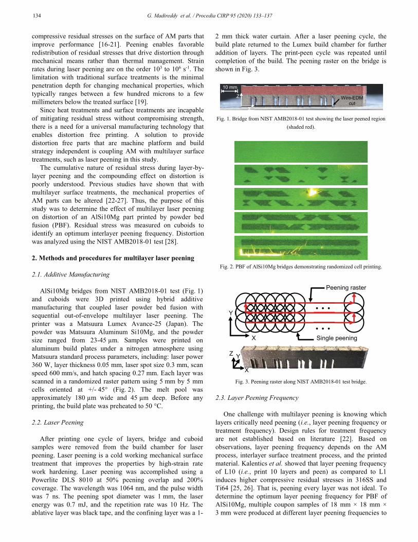
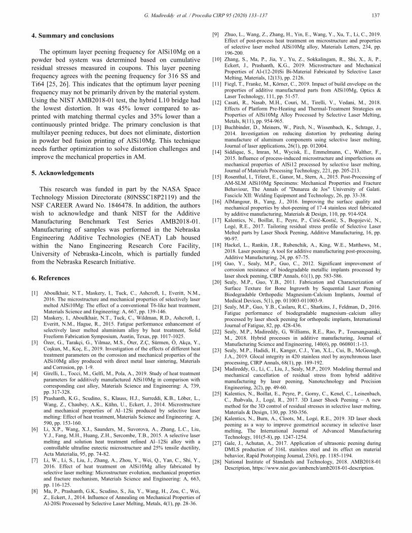
AlSi10Mg bridges from NIST AMB2018-01 test (Fig. 1) and cuboids were 3D printed using hybrid additive manufacturing that coupled laser powder bed fusion with sequential out-of-envelope multilayer laser peening. The printer was a Matsuura Lumex Avance-25 (Japan). The powder was Matsuura Aluminum Si10Mg, and the powder size ranged from 23-45 μm. Samples were printed on aluminum build plates under a nitrogen atmosphere using Matsuura standard process parameters, including: laser power 360 W, layer thickness 0.05 mm, laser spot size 0.3 mm, scan speed 600 mm/s, and hatch spacing 0.27 mm. Each layer was scanned in a randomized raster pattern using 5 mm by 5 mm cells oriented at +/- 45° (Fig. 2). The melt pool was approximately 180 μm wide and 45 μm deep. Before any printing, the build plate was preheated to 50 °C.
2.2. Laser Peening
After printing one cycle of layers, bridge and cuboid samples were removed from the build chamber for laser peening. Laser peening is a cold working mechanical surface treatment that improves the properties by high-strain rate work hardening. Laser peening was accomplished using a Powerlite DLS 8010 at 50% peening overlap and 200% coverage. The wavelength was 1064 nm, and the pulse width was 7 ns. The peening spot diameter was 1 mm, the laser energy was 0.7 mJ, and the repetition rate was 10 Hz. The ablative layer was black tape, and the confining layer was a 1-
2 mm thick water curtain. After a laser peening cycle, the build plate returned to the Lumex build chamber for further addition of layers. The print-peen cycle was repeated until completion of the build. The peening raster on the bridge is shown in Fig. 3.
Fig. 1. Bridge from NIST AMB2018-01 test showing the laser peened region
(shaded red).
Fig. 2. PBF of AlSi10Mg bridges demonstrating randomized cell printing.
Fig. 3. Peening raster along NIST AMB2018-01 test bridge.
2.3. Layer Peening Frequency
One challenge with multilayer peening is knowing which layers critically need peening (i.e., layer peening frequency or treatment frequency). Design rules for treatment frequency are not established based on literature [22]. Based on observations, layer peening frequency depends on the AM process, interlayer surface treatment process, and the printed material. Kalentics et al. showed that layer peening frequency of L10 (i.e., print 10 layers and peen) as compared to L1 induces higher compressive residual stresses in 316SS and Ti64 [25, 26]. That is, peening every layer was not ideal. To determine the optimum layer peening frequency for PBF of AlSi10Mg, multiple coupon samples of 18 mm × 18 mm × 3 mm were produced at different layer peening frequencies to
10 mm
X Z Wire-EDM
cut
… …
X
Y
Z Y
X
Single peening
Peening raster

G. Madireddy et al. / Procedia CIRP 95 (2020) 133–137 135
examine the cumulative residual stress development by hole drilling (Fig. 4). The coupon condition with minimal tensile stress through the depth was selected to print a hybrid bridge. The layer peening frequencies for measuring cumulative residual stresses were the following: (a) laser peening on the surface (surface peened), (b) peening every 20 layers (hybrid-L20), (c) peening every 10 layers (hybrid-L10), and (d) peening every four layers (hybrid-L4). A hybrid-L10 bridge was printed based on residual stress measurements.
Fig. 4. Hybrid-AM by PBF and laser peening of AlSi10Mg cuboids to
measure residual stress by hole drilling.
2.4. NIST AMB2018-01 Test
Three bridges were printed to examine distortion. The first two bridges were simultaneously printed together and matched thermal cycles; referred to as “hybrid-L10” and “as-printed (discontinuous).” It is important to match thermal cycles between bridges in order to isolate the effect of interlayer peening. The third bridge was continuously printed on a separate build plate without any intermittent stops or laser peening between layers and was referred to as “as-printed (continuous).” Intentionally, there was no thermal cycling of the third bridge.
The hybrid bridge was laser peened every 10 layers between layers 151 to 250. The struts of the bridge were not laser peened since these stresses will not directly affect the upward deflection of the bridge. The as-printed discontinuous bridge was not laser peened and matched the thermal cycles of the hybrid bridge. When the temperature of the bridges cooled down to room temperature, the build plate was removed from the Lumex build chamber for laser peening. When the build plate returned to the chamber and was elevated to 50 °C, the thermal gradient between the newly added layer and the previous layers was higher than a continuously printed part. Higher thermal gradients cause higher stresses in the build. After fabrication of the bridges, the twelve struts were cut using wire-EDM and the resulting upward deflection was measured using Vernier calipers.
3. Results and discussion
3.1. Residual stress
The layer peening frequency was determined based on accumulated residual stresses from the cuboid samples. Residual stress was measured using the hole drilling method
with an MTS 3000 from SINT Technologies. The surface of each sample was hand-polished using 320 and 400 grit sand papers to remove any surface irregularities from printing and peening that would prevent strain gage attachment. An HBM strain gauge (1-RY6-1.5/120K) was applied carefully on each polished surface of the sample and was drilled in 16 μm step increments at 400,000 RPM up to 2 mm in depth. In each step, the strain gauge captured strains relieved in the material during the drilling process. The residual stresses were calculated from the measured strains using the ASTM E837-13a algorithm. The results are plotted in Fig. 5 along the peening feed direction (�x).
For each condition, multiple samples were drilled to get the average variation of stress. In each graph, the red and blue curves represent the maximum and minimum value of stress at a particular depth increment, respectively. The black dotted curve represents the average of the stresses at that depth increment. Finally, the region between the maximum and minimum stress curves is shaded with yellow to represent the residual stress region in each case.
Fig. 5(a) shows the variation of stresses in the as-printed samples. The residual stresses were tensile and consistently oscillated with the addition of more layers. The tensile stresses ranged from 200-400 MPa. Results are consistent and typical of most metals produced by laser-based AM.
Fig. 5(b) shows the variation of residual stress in surface peened samples. At the top surface, a compressive hook formed that exceeded -400 MPa and is consistent with typically peening profiles. The mixed mode behavior was likely due to the manual polishing of the surface to remove irregularities from AM and laser peening. This affected the stresses in top 10-20 μm. Below the top surface, an average compressive stress of -100 MPa was observed. As the depth increased beyond 400 μm, the stress became increasingly tensile before interacting with bulk behavior.
Fig. 5(c) shows the stress profile from peening every 20 layers (i.e., every 1 mm). In this case, the stress profile was similar to the surface peened samples for the top 400 μm of material with an average compressive stress of -100 MPa. Beyond 500 μm into the substrate, the stress became tensile. Interestingly, the severity of the tensile peak diminishes because of recurrent peening. The average tensile stress at 1 mm reduced from 350 MPa in surface treated to 150 MPa in hybrid L20. The results demonstrate that cumulative stresses from coupling AM with laser peening improved the severity of tensile residual stress compared to as-printed and surface peened cases.
Fig. 5(d) shows the stress profile from peening every 10 layers (i.e., every 500 μm). Even in this profile, stresses were similar to the previous cases in the top 400 μm of material before turning tensile. However, a second compressive hook was observed after 1 mm depth. This indicates more compressive stresses were retained in the material from more frequent peening.
The previous case demonstrated more frequent peening retained more compressive stress deeper within the substrate. To further examine this behavior, another set of samples were printed with laser peening applied every four layers. Fig. 5(e)
20 mm
Surf
ace
peen
ed As-printed
Hybrid-L10
Hybrid-L20
Hybrid-L4
X
Y

136 G. Madireddy et al. / Procedia CIRP 95 (2020) 133–137
Fig. 5. Residual stresses varying along the depth in (a) as-printed, (b) surface
peened, (c) hybrid L20, (d) hybrid L10, and (e) hybrid L4.
shows the stress profile from peening every four layers (i.e., every 200 μm). In this case, the residual stress turned tensile sooner at 200 μm. It is possible this could be due to mechanical cancellation of stresses as described in [24]. It was shown that more frequent peening removes or negates the stresses developed from previous layers. There was no second
hook observed in this case, and the stresses remained tensile with an average magnitude below 100 MPa.
3.2. Bridges from NIST AMB2018-01
Based on residual stress data, the hybrid condition of L10 was chosen due to minimum tensile residual stress. Three bridges from NIST AMB2018-01 test were manufactured: hybrid L10, as-printed (discontinuous), as-printed (continuous). The discontinuous and hybrid bridges matched thermal cycles during printing. The struts of all bridges were cut using wire-EDM to measure the amount of upward deflection (Fig. 6). The magnitude of the deflection was measured and plotted in Fig. 7.
Fig. 6. Deflection in NIST AMB2018-01 bridges after wire-EDM.
Fig. 7. Deflection measurements of bridges after wire-EDM. From the results, the deflection of the as-printed
(discontinuous) sample that matched the thermal cycles of the hybrid sample exhibited the highest deflection of 0.78 mm. This indicates higher tensile residual stresses due to the increased thermal gradients. The continuously printed sample had a maximum deflection of 0.66 mm. This indicates that even if the thermal gradient is not high, the continuous heat supply into the material induces tensile stresses in the bridge. Interestingly, the hybrid bridge had the lowest deflection and was 0.43 mm. The results indicate peening every 10 layers reduced distortion approximately 45%.
Hybrid L10 As-printed (discontinuous)
10 mm X
Z
Y Z 5 mm
As-printed (continuous)
-0.2
0
0.2
0.4
0.6
0.8
1
0 20 40 60 80
Upward de
flection:
+Z
(mm
)
X (mm)
As-printed (continuous)
As-printed (discontinuous)
Hybrid L10
-400
-300
-200
-100
0
100
200
300
400
0 0.2 0.4 0.6 0.8 1 1.2� x(M
Pa)
Depth (mm)
(a)
-400
-300
-200
-100
0
100
200
300
400
0 0.2 0.4 0.6 0.8 1 1.2� x(M
Pa)
Depth (mm)
(b)
-400
-300
-200
-100
0
100
200
300
400
0 0.2 0.4 0.6 0.8 1 1.2� x(M
Pa)
Depth (mm)
(c)
-400
-300
-200
-100
0
100
200
300
400
0 0.2 0.4 0.6 0.8 1 1.2� x(M
Pa)
Depth (mm)
(d)
-400
-300
-200
-100
0
100
200
300
400
0 0.2 0.4 0.6 0.8 1 1.2� x(M
Pa)
Depth (mm)
(e)
G. Madireddy et al. / Procedia CIRP 95 (2020) 133–137 137
4. Summary and conclusions
The optimum layer peening frequency for AlSi10Mg on a powder bed system was determined based on cumulative residual stresses measured in coupons. This layer peening frequency agrees with the peening frequency for 316 SS and Ti64 [25, 26]. This indicates that the optimum layer peening frequency may not be primarily driven by the material system. Using the NIST AMB2018-01 test, the hybrid L10 bridge had the lowest distortion. It was 45% lower compared to as-printed with matching thermal cycles and 35% lower than a continuously printed bridge. The primary conclusion is that multilayer peening reduces, but does not eliminate, distortion in powder bed fusion printing of AlSi10Mg. This technique needs further optimization to solve distortion challenges and improve the mechanical properties in AM.
5. Acknowledgements
This research was funded in part by the NASA Space Technology Mission Directorate (80NSSC18P2119) and the NSF CAREER Award No. 1846478. In addition, the authors wish to acknowledge and thank NIST for the Additive Manufacturing Benchmark Test Series AMB2018-01. Manufacturing of samples was performed in the Nebraska Engineering Additive Technologies (NEAT) Lab housed within the Nano Engineering Research Core Facility, University of Nebraska-Lincoln, which is partially funded from the Nebraska Research Initiative.
6. References
[1] Aboulkhair, N.T., Maskery, I., Tuck, C., Ashcroft, I., Everitt, N.M., 2016. The microstructure and mechanical properties of selectively laser melted AlSi10Mg: The effect of a conventional T6-like heat treatment, Materials Science and Engineering: A, 667, pp. 139-146.
[2] Maskery, I., Aboulkhair, N.T., Tuck, C., Wildman, R.D., Ashcroft, I., Everitt, N.M., Hague, R., 2015. Fatigue performance enhancement of selectively laser melted aluminium alloy by heat treatment, Solid Freeform Fabrication Symposium, Austin, Texas, pp. 1017-1025.
[3] Özer, G., Tarakçi, G., Yilmaz, M.S., Öter, Z.Ç, Sürmen, Ö, Akça, Y., !�"#�$�&$'�<$�&$��=>&���� ��?Q��������������� �������������at treatment parameters on the corrosion and mechanical properties of the AlSi10Mg alloy produced with direct metal laser sintering, Materials and Corrosion, pp. 1-9.
[4] Girelli, L., Tocci, M., Gelfi, M., Pola, A., 2019. Study of heat treatment parameters for additively manufactured AlSi10Mg in comparison with corresponding cast alloy, Materials Science and Engineering: A, 739, pp. 317-328.
[5] Prashanth, K.G., Scudino, S., Klauss, H.J., Surreddi, K.B., Löber, L., Wang, Z., Chaubey, A.K., Kühn, U., Eckert, J., 2014. Microstructure and mechanical properties of Al–12Si produced by selective laser melting: Effect of heat treatment, Materials Science and Engineering: A, 590, pp. 153-160.
[6] Li, X.P., Wang, X.J., Saunders, M., Suvorova, A., Zhang, L.C., Liu, Y.J., Fang, M.H., Huang, Z.H., Sercombe, T.B., 2015. A selective laser melting and solution heat treatment refined Al–12Si alloy with a controllable ultrafine eutectic microstructure and 25% tensile ductility, Acta Materialia, 95, pp. 74-82.
[7] Li, W., Li, S., Liu, J., Zhang, A., Zhou, Y., Wei, Q., Yan, C., Shi, Y., 2016. Effect of heat treatment on AlSi10Mg alloy fabricated by selective laser melting: Microstructure evolution, mechanical properties and fracture mechanism, Materials Science and Engineering: A, 663, pp. 116-125.
[8] Ma, P., Prashanth, G.K., Scudino, S., Jia, Y., Wang, H., Zou, C., Wei, Z., Eckert, J., 2014. Influence of Annealing on Mechanical Properties of Al-20Si Processed by Selective Laser Melting, Metals, 4(1), pp. 28-36.
[9] Zhuo, L., Wang, Z., Zhang, H., Yin, E., Wang, Y., Xu, T., Li, C., 2019. Effect of post-process heat treatment on microstructure and properties of selective laser melted AlSi10Mg alloy, Materials Letters, 234, pp. 196-200.
[10] Zhang, S., Ma, P., Jia, Y., Yu, Z., Sokkalingam, R., Shi, X., Ji, P., Eckert, J., Prashanth, K.G., 2019. Microstructure and Mechanical Properties of Al-(12-20)Si Bi-Material Fabricated by Selective Laser Melting, Materials, 12(13), pp. 2126.
[11] Fiegl, T., Franke, M., Körner, C., 2019. Impact of build envelope on the properties of additive manufactured parts from AlSi10Mg, Optics & Laser Technology, 111, pp. 51-57.
[12] Casati, R., Nasab, M.H., Couri, M., Tirelli, V., Vedani, M., 2018. Effects of Platform Pre-Heating and Thermal-Treatment Strategies on Properties of AlSi10Mg Alloy Processed by Selective Laser Melting, Metals, 8(11), pp. 954-965.
[13] Buchbinder, D., Meiners, W., Pirch, N., Wissenbach, K., Schrage, J., 2014. Investigation on reducing distortion by preheating during manufacture of aluminum components using selective laser melting, Journal of laser applications, 26(1), pp. 012004.
[14] Siddique, S., Imran, M., Wycisk, E., Emmelmann, C., Walther, F., 2015. Influence of process-induced microstructure and imperfections on mechanical properties of AlSi12 processed by selective laser melting, Journal of Materials Processing Technology, 221, pp. 205-213.
[15] Rosenthal, I., Tiferet, E., Ganor, M., Stern, A., 2015. Post-Processing of AM-SLM AlSi10Mg Specimens: Mechanical Properties and Fracture Behaviour, The Annals of "Dunarea de Jos" University of Galati. Fascicle XII: Welding Equipment and Technology, 26, pp. 33-38.
[16] AlMangour, B., Yang, J., 2016. Improving the surface quality and mechanical properties by shot-peening of 17-4 stainless steel fabricated by additive manufacturing, Materials & Design, 110, pp. 914-924.
[17] 'Q������ $ `&$ {����Q�$ �&$ �����$ �&$ |���}-'� ��}$ �&$ {�?�~���}$ `&$Logé, R.E., 2017. Tailoring residual stress profile of Selective Laser Melted parts by Laser Shock Peening, Additive Manufacturing, 16, pp. 90-97.
[18] Hackel, L., Rankin, J.R., Rubenchik, A., King, W.E., Matthews, M., 2018. Laser peening: A tool for additive manufacturing post-processing, Additive Manufacturing, 24, pp. 67-75.
[19] Guo, Y., Sealy, M.P., Guo, C., 2012. Significant improvement of corrosion resistance of biodegradable metallic implants processed by laser shock peening, CIRP Annals, 61(1), pp. 583-586.
[20] Sealy, M.P., Guo, Y.B., 2011. Fabrication and Characterization of Surface Texture for Bone Ingrowth by Sequential Laser Peening Biodegradable Orthopedic Magnesium-Calcium Implants, Journal of Medical Devices, 5(1), pp. 011003-011003-9.
[21] Sealy, M.P., Guo, Y.B., Caslaru, R.C., Sharkins, J., Feldman, D., 2016. Fatigue performance of biodegradable magnesium–calcium alloy processed by laser shock peening for orthopedic implants, International Journal of Fatigue, 82, pp. 428-436.
[22] Sealy, M.P., Madireddy, G, Williams, R.E., Rao, P., Toursangsaraki, M., 2018. Hybrid processes in additive manufacturing, Journal of Manufacturing Science and Engineering, 140(6), pp. 060801:1-13.
[23] Sealy, M.P., Hadidi, H., Kanger, C.J., Yan, X.L., Cui, B., McGeough, J.A., 2019. Glocal integrity in 420 stainless steel by asynchronous laser processing, CIRP Annals, 68(1), pp. 189-192.
[24] Madireddy, G., Li, C., Liu, J., Sealy, M.P., 2019. Modeling thermal and mechanical cancellation of residual stress from hybrid additive manufacturing by laser peening, Nanotechnology and Precision Engineering, 2(2), pp. 49-60.
[25] Kalentics, N., Boillat, E., Peyre, P., Gorny, C., Kenel, C., Leinenbach, C., Jhabvala, J., Logé, R., 2017. 3D Laser Shock Peening – A new method for the 3D control of residual stresses in selective laser melting, Materials & Design, 130, pp. 350-356.
[26] Kalentics, N., Burn, A., Cloots, M., Logé, R.E., 2019. 3D laser shock peening as a way to improve geometrical accuracy in selective laser melting, The International Journal of Advanced Manufacturing Technology, 101(5-8), pp. 1247-1254.
[27] Gale, J., Achutan, A., 2017. Application of ultrasonic peening during DMLS production of 316L stainless steel and its effect on material behavior, Rapid Prototyping Journal, 23(6), pp. 1185-1194.
[28] National Institute of Standards and Technology, 2018. AMB2018-01 Description, https://www.nist.gov/ambench/amb2018-01-description.