distributed broadcast file system configuration guide · although many cable operators are able to...
TRANSCRIPT

4017541 Rev B
Distributed Broadcast File System Configuration Guide For System Releases 2.7, 3.7, and 4.2


Please Read
Important
Please read this entire guide. If this guide provides installation or operation instructions, give particular attention to all safety statements included in this guide.

Notices
Trademark Acknowledgments
Cisco and the Cisco logo are trademarks or registered trademarks of Cisco and/or its affiliates in the U.S. and other countries. A listing of Cisco's trademarks can be found at www.cisco.com/go/trademarks.
Third party trademarks mentioned are the property of their respective owners.
The use of the word partner does not imply a partnership relationship between Cisco and any other company. (1009R)
Publication Disclaimer
Cisco Systems, Inc. assumes no responsibility for errors or omissions that may appear in this publication. We reserve the right to change this publication at any time without notice. This document is not to be construed as conferring by implication, estoppel, or otherwise any license or right under any copyright or patent, whether or not the use of any information in this document employs an invention claimed in any existing or later issued patent.
Copyright
© 2007, 2012 Cisco and/or its affiliates. All rights reserved. Printed in the United States of America.
Information in this publication is subject to change without notice. No part of this publication may be reproduced or transmitted in any form, by photocopy, microfilm, xerography, or any other means, or incorporated into any information retrieval system, electronic or mechanical, for any purpose, without the express permission of Cisco Systems, Inc.

4017541 Rev B iii
Contents
About This Guide v
Chapter 1 Distributed BFS Plant Configurations 1
Overview ................................................................................................................................... 2 Data Transmission Options .................................................................................................... 3
ATM Distributed BFS Plant Configurations ........................................................................ 4
ASI Distributed BFS Plant Configurations ........................................................................... 6
Process Overview ..................................................................................................................... 8
Chapter 2 DNCS Configuration for Distributed BFS 9
Time to Complete ................................................................................................................... 10
Pre-Configuration Tasks ....................................................................................................... 11 Add an MPEG Source ........................................................................................................... 12
Add Another BFS QAM to the DNCS ................................................................................. 16
Set Up CF Sessions for the Additional BFS QAM ............................................................. 22
Add a New OSM Source, Source Definition, and Session ............................................... 31
Worksheet ............................................................................................................................... 35
Chapter 3 Enabling CVT Downloads on the DNCS 37
Overview ................................................................................................................................. 38
Confirming That All DNCS Processes Are Running ........................................................ 39
Adding OSM Entries to the DNCS .profile File ................................................................. 41
Gather Information for the osmAutoMux.cfg File ............................................................ 42
Gather Information for Your OSM Configuration File ..................................................... 48
Review Record Layout Examples ........................................................................................ 50 Configuring the osmAutoMux.cfg File ............................................................................... 51
Removing OSM Entries From the DNCS .profile userid File .......................................... 53
Testing the Distributed BFS Configuration ........................................................................ 54
Chapter 4 Disabling OSM Automux 55
Before You Begin .................................................................................................................... 56
Checking BFS QAM Frequencies ......................................................................................... 57
Verify Program Numbers ..................................................................................................... 58 Removing OSM Entries From the DNCS .profile userid File .......................................... 61
Bouncing the OSM Process ................................................................................................... 62

Contents
iv 4017541 Rev B
Chatper 5 Removing the Distributed BFS Configuration From the DNCS 63
Removing the OSM Source, Source Definition, and Session ........................................... 64
Removing CF Sessions for the Additional BFS QAMs ..................................................... 65 Removing MPEG Sources ..................................................................................................... 66
Chapter 6 Customer Information 67

About This Guide
4017541 Rev B v
About This Guide
Introduction
Although many cable operators are able to transport data to Broadcast File System (BFS) Quadrature Amplitude Modulation modulators (QAMs) at different locations, there is currently no standard method for configuring a system to support distributed BFS. Cisco developed this guide to provide the recommended methods for configuring a system to support distributed BFS.
In addition, this guide provides instructions for enabling the Code Version Table (CVT) download method for distributed BFS. With the CVT download method, you must add a data carousel (the Operating System Manager [OSM]) onto the additional BFS QAM. The normal process for setting up a distributed BFS assumes that all BFS carousels have a source, a source definition, and a session. The OSM carousel for a CVT download does not follow this normal process. Therefore, sites that use a distributed BFS must take additional steps to manage this unique carousel.
Purpose
This guide provides a recommended method for setting up a system that supports a distributed BFS and the CVT download method. As you configure your system, you branch into different procedures depending on your network configuration. Specifically, you must complete additional procedures to enable OSM Automux if your site uses one or both of the following network configurations:
The multiplexing devices output program numbers that do not match the program numbers going to the primary BFS QAM
The distributed BFS QAMs and the primary BFS QAM do not share the same frequency
If you decide to change your network configuration later on, you can always disable OSM Automux using the procedures provided in Disabling OSM Automux (on page 55). Removing the Distributed BFS Configuration From the DNCS (on page 63) details how to remove the entire distributed BFS configuration.
Audience
This guide is written for operators of Cisco's digital cable television systems that use the Cisco Resident Application (SARA). DNCS operators, Cisco field service engineers, and Cisco Services engineers may also find the information in this guide helpful.
Anyone performing the procedures in this guide must be proficient in using basic UNIX commands and a UNIX-based text editor.

About This Guide
vi 4017541 Rev B
Scope
This guide is written for systems running System Releases (SR) 2.7, SR 3.7, or SR 4.2 and related Service Packs.
Related Publications
You may find the following publications useful as resources when you implement the procedures in this document. Check the copyright date on your resources to assure that you have the most current version. The publish dates for the following documents are valid as of this printing. However, some of these documents may have since been revised:
DBDS Backup and Restore Procedures For System Releases 2.2 through 4.2 (part number 4013779, published December 2006)
DNCS Online Help (PC) 4.2.0.3 (part number 4012121, published December 2006)
DNCS Online Help (UNIX) 4.2.0.3 (part number 4012122, published December 2006)
Distributed EAS on the Regional Control System, Configuration and Troubleshooting Guide (part number 4002342, published June 2005)
Dual SFP Gigabit QAM Modulator Installation and Operation Guide (part number 4014102, published December 2006)
RNCS Installation and Upgrade Instructions for SR 2.7/3.7 or SR 4.2 (part number 4012763, published December 2006)
System Release 2.7 Release Notes (part number 4012155, published March 2007)
System Release 3.7 Release Notes (part number 4012156, published March 2007)
System Release 4.2 Release Notes (part number 4012157, published March 2007)
Document Version
This is the second release of this document.

4017541 Rev B 1
Introduction
This chapter discusses the recommended plant configurations you can use to support distributed BFS.
1 Chapter 1 Distributed BFS Plant Configurations
In This Chapter
Overview .................................................................................................. 2
Data Transmission Options ................................................................... 3
ATM Distributed BFS Plant Configurations ....................................... 4
ASI Distributed BFS Plant Configurations .......................................... 6
Process Overview ................................................................................... 8

Chapter 1 Distributed BFS Plant Configurations
2 4017541 Rev B
Overview Cisco developed this guide to identify the recommended configurations to support distributed BFS.
Frequency Configuration
Some service providers might configure their plant with more than one BFS QAM. For these sites, the QAMs can be configured with overlapping frequencies or non-overlapping frequencies (known as a split plant). The term overlapping frequencies means the distributed BFS QAMs use the same frequency as the primary BFS QAM. The term non-overlapping frequencies means the distributed BFS QAMs and primary BFS QAM use different frequencies.
Using Multiplexing Devices
For either of these frequency architectures, a multiplexing device can be added to provide secondary video through the BFS QAMs. Examples of multiplexing devices include Cherry Pickers, Grooming Broadband Integrated Gateways (BIGs), or BitMizer™ devices. You can also use a media converter, such as a SWIF-to-ASI converter, for distributing BFS without adding content to your BFS QAM.
No matter which multiplexing device you use, Cisco strongly recommends that you configure the multiplexing devices to output program numbers that match the program numbers going to the primary BFS QAM. This configuration ensures that the program numbers going into the distributed BFS QAMs match the program numbers going into the primary BFS QAM.
The program numbers in the Broadband Integrated Gateway Program Allocation Table (BIG PAT) table are very important when configuring the multiplexing devices to support the distributed BFS configuration. By configuring your multiplexing devices to use the same program numbers defined in the BIG PAT table, you can ensure that the program numbers match among the primary BFS QAM and all the distributed BFS QAMs.
OSM Automux
If you match program numbers and use overlapping frequencies, it is not necessary to use OSM Automux. Otherwise, you have to use OSM Automux to identify QAMs that need to carry a unique Code Version Table (CVT).
If you do not want the primary BFS QAM to provide any RF signal, you can configure one or more secondary BFS QAMs to provide all BFS data.

Data Transmission Options
4017541 Rev B 3
Data Transmission Options Service providers may choose to configure their plant to use one of the following data interface cards:
Asynchronous Serial Interface (ASI)
- Direct ASI does not use a BIG
- Inband data is sent directly from the DNCS to the BFS QAM and secondary QAMs through an ASI interface using a splitter or a multiplexing (MUX) device
SWIF
- SWIF requires the use of a BIG
- Inband data is sent through the asynchronous transfer mode (ATM) interface
- A media converter or a MUX device is required to convert SWIF input to another QAM input, such as ASI
Notes:
Most multiplexing devices convert SWIF input to ASI input, which provides a method to manage and combine video streams. Instead of a multiplexing device, you can use a media converter to convert the SWIF input to one of the other QAM inputs, such as ASI. In either case, you cannot select SWIF as an input source to the additional BFS QAMs.
The DNCS cannot send inband data through the ATM and ASI interfaces simultaneously.

Chapter 1 Distributed BFS Plant Configurations
4 4017541 Rev B
ATM Distributed BFS Plant Configurations This section details two types of ATM transport configurations for setting up a plant with one or more secondary BFS QAMs.
Note: The diagrams in this section include emulated MPEG devices. These devices do not exist physically in the plant; however, you must configure this device on the DNCS. The emulated MPEG allows the secondary BFS QAM to receive data through the ASI transport.
Designing the Plant to Use a MUX Device
The numbers in the diagram refer to the following notes:
The plant includes a MUX device to convert the SWIF input to ASI. The MUX device can send a separate signal to each secondary BFS QAM.
The plant includes one or more secondary BFS QAMs.
The primary BFS QAM can optionally be configured to feed BFS data to the plant.
The primary BFS QAM and secondary BFS QAM can be at the same frequency or different frequencies (split plant).

ATM Distributed BFS Plant Configurations
4017541 Rev B 5
Designing the Plant to Use an ASI Splitter
The numbers in the diagram refer to the following notes:
The plant includes an ASI splitter to distribute the ASI stream to the primary and secondary BFS QAMs.
The plant includes one or more secondary BFS QAMs.
The primary BFS QAM can optionally be configured to feed BFS data to the plant.
The primary BFS QAM and secondary BFS QAM can be at the same frequency or different frequencies (split plant).

Chapter 1 Distributed BFS Plant Configurations
6 4017541 Rev B
ASI Distributed BFS Plant Configurations This section details two types of ASI transport configurations for setting up a plant with one or more secondary BFS QAMs.
Note: The diagrams in this section include emulated MPEG devices. These devices do not exist physically in the plant; however, you must configure this device on the DNCS. The emulated MUX allows the secondary BFS QAM to receive data through the ASI transport.
Designing the Plant to Use a MUX Device
The numbers in the diagram refer to the following notes:
The plant includes a MUX device to send a separate signal to each BFS QAM in the plant configuration.
The plant includes one or more secondary BFS QAMs.
The primary BFS QAM can optionally be configured to feed BFS data to the plant.
The primary BFS QAM and secondary BFS QAM can be at the same frequency or different frequencies (split plant).

ASI Distributed BFS Plant Configurations
4017541 Rev B 7
Designing the Plant to Use an ASI Splitter
The numbers in the diagram refer to the following notes:
The plant includes an ASI splitter to distribute the ASI stream to the primary and secondary BFS QAMs.
The plant includes one or more secondary BFS QAMs.
The primary BFS QAM can optionally be configured to feed BFS data to the plant.
The primary BFS QAM and secondary BFS QAM can be at the same frequency or different frequencies (split plant).
Chapter 1 Distributed BFS Plant Configurations
8 4017541 Rev B
Process Overview Regardless of the particular configuration you use, the basic process for setting up a distributed BFS is the same. In each case, you will perform the following tasks.
1 Configure the emulated MUX.
2 Configure the secondary BFS QAM.
3 Add the sessions to the secondary BFS QAM.
4 Configure the system for CVT for the secondary BFS QAM.
Note: You will complete some additional steps to configure OSM Automux if you are using non-overlapping frequencies, different program numbers, or both.

4017541 Rev B 9
Introduction
This chapter provides instructions for configuring a DNCS for Distributed BFS.
2 Chapter 2 DNCS Configuration for Distributed BFS
In This Chapter
Time to Complete ................................................................................. 10
Pre-Configuration Tasks ...................................................................... 11
Add an MPEG Source .......................................................................... 12
Add Another BFS QAM to the DNCS ............................................... 16
Set Up CF Sessions for the Additional BFS QAM ............................ 22
Add a New OSM Source, Source Definition, and Session .............. 31
Worksheet .............................................................................................. 35

Chapter 2 DNCS Configuration for Distributed BFS
10 4017541 Rev B
Time to Complete Considering some small differences in the procedure for adding a BFS QAM, this procedure can take from 2 to 4 hours to complete.

Pre-Configuration Tasks
4017541 Rev B 11
Pre-Configuration Tasks This section describes two important tasks you must complete before you begin configuring your system for distributed BFS.
Locate Your Network Map
It is essential to have key information in front of you when configuring your system for distributed BFS. Make sure you have your network map before you begin configuring your DNCS for Distributed BFS. If you cannot locate your network map, contact Cisco Services. You must also have the following information:
Name you want to use to identify the device
Type of output card installed in the device (ASI, DHEI, or SWIF)
Number identifying the output port on the device that is physically connected to the input port on the associated service QAM
Number identifying the output transport stream ID coming from the multiplexing device to the associated service QAM
Note: All of this information should be recorded on your network map. However, if it is not, contact your system administrator to obtain the information.
Decide if OSM Automux is Required
As you configure your system, your answers to certain questions depend on whether OSM Automux is required. Before you begin configuring distributed BFS, determine if your system requires OSM Automux.
Your system requires OSM Automux if your site plans to use one or both of the following network configurations:
The multiplexing devices output program numbers that do not match the program numbers going to the primary BFS QAM.
The distributed BFS QAMs and the primary BFS QAM do not share the same frequency.

Chapter 2 DNCS Configuration for Distributed BFS
12 4017541 Rev B
Add an MPEG Source This section provides instructions for adding an emulated MUX to the DNCS for a distributed BFS. When you add an emulated MUX to the DNCS, you add it as an MPEG source, name it BFS MUX, and either choose or type MUX as the device type.
Note: The MPEG source device types serve only as placeholders.
If you already have an emulated MUX and secondary BFS QAM configured, you can skip this section and go to Add a New OSM Source, Source Definition, and Session (on page 31).
When adding an MPEG source to the DNCS, you must set up the basic parameters and establish the connectivity from the MPEG source to the BFS QAMs.
Setting Up Basic Parameters for the MPEG Source 1 On the DNCS Administrative Console, click the DNCS tab.
2 Click the Network Element Provisioning tab.
3 Click MPEG Source. The MPEG Source List window opens.

Add an MPEG Source
4017541 Rev B 13
4 On the File menu, click New. The Set Up MPEG Source window opens with the Basic Parameters tab in the forefront.
5 Click the Headend Name arrow and select the headend to which you want to associate this MPEG source.
6 In the MPEG Source Name box, type the name of the device (for example, CherryPicker1). You can use up to 20 alphanumeric characters.
7 Click in the Device Type box and select or type MUX.
Note: You may select any device type. However, for consistency Cisco recommends that you use MUX.
8 In the IP Address box, type an IP address for the device.
Note: Because the DNCS does not manage this device, this IP address only serves as a placeholder; you cannot use the IP address to ping the device.
9 In the Physical Address box, type a MAC address for the device.
Note: This MAC address also serves as a placeholder. You may use any address that complies with the standard. For example, A1:A1:A1:A1:A1:A1 or B2:B2:B2:B2:B2:B2.
10 Click Apply. The DNCS saves the basic parameters for this device in the DNCS database and the previously disabled Connectivity tab becomes available.

Chapter 2 DNCS Configuration for Distributed BFS
14 4017541 Rev B
Establishing Connectivity Parameters for the MPEG Source
The second step in adding a device to your DNCS is to establish the connectivity from the MPEG source to the BFS QAMs.
1 Click the Connectivity tab in the Setup MPEG Source window. The Connectivity tab appears in the forefront with an illustration of any devices already connected to this MPEG source. If no devices are connected, the illustration area is empty.
2 Click Create Port. The Port Number Prompt window opens.
3 In the Port Number box, type 1. This number identifies the output port on this MPEG source.

Add an MPEG Source
4017541 Rev B 15
4 In the Transport Stream ID box, type the number that identifies the transport stream going from this MPEG source to the associated BFS QAM.
Note: This number must correspond with the ASI input (usually on your network map) on the associated QAM.
5 Record the Transport Stream ID here ________. You will need this number if you add another BFS QAM to the DNCS.
6 In the Transport Protocol field, select ASI.
Note: Typically, multiplexing devices or translators use ASI transport mode. If you are setting up an emulated MUX for a multiplexing device, select ASI.
7 Click OK. The DNCS saves this information, closes the Port Number Prompt window, and then updates the Connectivity tab with the new port and transport stream information.
8 Click Save to save your changes.
9 Close the the MPEG Source window from the File menu.
10 Close the MPEG Source List window from the File menu.
11 Do you need to add other MPEG sources for additional secondary BFS QAMs?
If yes, repeat the Setting Up Basic Parameters for the MPEG Source procedure and this procedure up to this point for each additional MPEG source. Then go to step 12.
If no, go to step 12.
12 Do you already have additional BFS QAM(s) in your DNCS to associate with the MPEG source(s)?
If yes, go to Setting Up Additional BFS QAM and MPEG Source Connectivity (on page 20).
If no, go to Add Another BFS QAM to the DNCS (on page 16).

Chapter 2 DNCS Configuration for Distributed BFS
16 4017541 Rev B
Add Another BFS QAM to the DNCS After you add an emulated MUX to the DNCS, your next step is to add another BFS QAM to the DNCS database to receive data from that device. This section provides instructions for adding another BFS QAM to the DNCS.
Note: If you already have another BFS QAM in your system, you do not need to add one.
Before You Begin
Before you add another BFS QAM to the DNCS, you must have your network map. If you cannot locate your network map, contact Cisco Services. You must also have the following information:
Name of the headend containing the QAM
Name used to identify the QAM
IP address for the QAM (from your system administrator)
MAC address for the QAM
Subnet mask for the QAM (from your system administrator)
Type of input interface that will be receiving data from the associated device (ASI, DHEI, or SWIF)
Note: Verify that the QAM you are using has inputs compatible with the outputs of your multiplexing device.
A number that identifies the transport stream going from the QAM out to the hubs on your system
Type of modulation the QAM uses (ITU B, 64 QAM or ITU B, 256 QAM)
Frequency of the channel being used to send data from the QAM to the hubs on your system
Names of the hubs you want to receive data from this QAM
A number that identifies the input port on this QAM
Name of the headend containing the associated device
Type of device being used to send data to this BFS QAM (based on the device you chose when you added a device to the DNCS [for example, MUX])
Name of the device you entered when you added the device to the DNCS
The number you entered as the output port of the device that is physically connected to the input port on this BFS QAM

Add Another BFS QAM to the DNCS
4017541 Rev B 17
Note: All of this information should be recorded on your network map. However, if it is not, contact your system administrator to obtain the information.
To add another BFS QAM to the DNCS, complete all of the instructions in this section in the order in which they appear.
Setting up Basic Parameters for the BFS QAM
The first step in adding another BFS QAM is to set up the basic parameters for the BFS QAM.
1 On the DNCS Administrative Console, click the DNCS tab.
2 Click the Network Element Provisioning tab.
3 Click QAM. The QAM List window opens.
4 On the File menu, select New and click QAM. The Set Up QAM window opens with the Basic Parameters tab in the forefront.
5 Click the Headend Name arrow and select the headend in which this service QAM resides.

Chapter 2 DNCS Configuration for Distributed BFS
18 4017541 Rev B
6 In the QAM Name box, type the name you will use to identify this QAM (for example, BFSQAM2).
Note: You can use up to 15 alphanumeric characters. Be sure to use a name that is consistent with the naming scheme used on your network map.
7 In the IP Address box, type the IP address for this QAM.
8 Click the Modulation Type arrow and select the modulation type.
Important! The modulation type must be the same as the modulation type used by the primary BFS QAM.
9 In the MAC Address box, type the MAC address for this QAM.
10 In the Subnet Mask box, type the subnet mask based on the following guidelines:
If your system uses a standard network configuration, type 255.255.255.0.
If your system uses another type of network configuration, type the subnet mask as assigned by your system administrator.
11 In the Default Gateway box, type the IP address of the default gateway.
12 For the Input Port, click the ASI option.
13 Will the QAM carry inband SI (system information)?
If yes, select Yes for Allow SI.
If no, select No for Allow SI.
14 In the INPUT Transport Stream ID box, type the transport stream ID.
Note: This ID must be the same as the output transport stream ID from the MPEG source. You recorded this number in step 5 of Establishing Connectivity Parameters for the MPEG Source (on page 14).
15 In the RF OUT row, complete the following information:
a Click the Modulation Type arrow and select the type of modulation this QAM uses.
b In the Transport Stream ID box, type the last octet of the IP address. This number identifies the transport stream going from this QAM out to the hubs on your system.
c In the Channel Center Frequency (MHz) box, type the channel frequency that you will use to send service information to set-tops on this headend. Cisco recommends that you enter a value in 6 MHz increments from 91 to 867.
16 Click Apply. The DNCS saves the QAM information you have entered up to this point in the DNCS database and activates the Hubs button.
17 Click Hubs. The RF Output Port window opens, showing the hubs that are available to receive data from this QAM modulator.
18 Select a hub that will receive data from this QAM in the Available Hubs field, and then click Add. The hub name moves into the Selected Hubs field.
19 Repeat step 18 for each hub that will receive data from this QAM.

Add Another BFS QAM to the DNCS
4017541 Rev B 19
20 Click Save. The RF Output Port window closes.
21 Click Apply. The DNCS saves the QAM information you have entered up to this point in the DNCS database.
Setting Up Advanced Parameters for the BFS QAM
After you set up the basic parameters for the additional BFS QAM, the next step is to configure the advanced parameters.
1 On the Set Up QAM window, click the Advanced Parameters tab.
Important! The DNCS inserts the Configuration File Name automatically. Do not change this field without first consulting with Cisco Services. The system configuration file specifies the software version that the QAM should be operating.
2 Click Apply. The DNCS saves the QAM modulator information you have entered thus far into the DNCS database.

Chapter 2 DNCS Configuration for Distributed BFS
20 4017541 Rev B
Setting Up Additional BFS QAM and MPEG Source Connectivity
Complete these steps to set up the connectivity between the additional BFS QAM and the MPEG source or associated device.
1 On the Set Up QAM window, click the Connectivity tab. The Connectivity tab opens with a graphical representation of the devices already connected to this QAM (if any).
2 If not already selected, click to select the Input Port option in the QAM Name area.
3 In the Connect To area, click the Headend Name arrow and select the headend that contains the device that is physically connected to this QAM.
4 Click the Device Type arrow and select the type of device being used to send data to this QAM (for example, MUX).
Note: We chose MUX as the device type when we added the device to the DNCS earlier in this section.
5 Click the Device Name arrow and select the name you entered for the device.
Notes:
The options that appear on the window after this step are dependent upon the Device Type you selected in step 4.
When entering information in this window, remember that the information is about the multiplexing device or translator you are associating with the additional BFS QAM.
If the transport stream IDs do not match, a device will not appear.
6 Click Apply. The DNCS saves this information into the DNCS database.
7 Your next step is to activate the QAM by placing it online. Go to Activating the Additional BFS QAM, next in this section.

Add Another BFS QAM to the DNCS
4017541 Rev B 21
Activating the Additional BFS QAM
After you set up the connectivity between the additional BFS QAM and the MPEG source or associated device, complete these steps to activate the BFS QAM by placing it online.
Note: You can activate a BFS QAM only after all parameters for the QAM have been saved to the DNCS database and the QAM has finished its boot process. Therefore, you may have to wait a few minutes before you can complete this task.
1 On the Set Up QAM window, click the Basic Parameters to bring it to the forefront.
2 For Administrative State, select the Online option.
3 Click Save and then click Close. The DNCS saves the QAM information, closes the Set Up QAM window, and updates the QAM List window to include the new QAM.
4 Do you need to add another BFS QAM?
If yes, complete the steps in Setting up Basic Parameters for the BFS QAM (on page 17), then go to step 5.
If no, go to step 5.
5 From the QAM List window, highlight the Primary BFS QAM.
6 On the File menu, select Open.
7 In the Basic Parameters tab of the Primary BFS Qam, select Hubs. The RF Output Port window opens, showing the hubs that are available to receive data from this QAM modulator.
8 Select a hub that will receive data from this QAM in the Available Hubs field, and then click Add. The hub moves into the Selected Hubs field.
9 Repeat step 8 for each hub that will receive data from this QAM.
10 Click Save. The RF Output Port window closes.
11 From Set Up QAM window, click Save and then click Close. The DNCS saves the QAM information, closes the Set Up QAM window.
12 Close the QAM list window from the File menu.
13 Your next step is to set up the CF sessions that will be transporting data from the multiplexing device to the BFS QAMs. Go to Set Up CF Sessions for the Additional BFS QAM (on page 22).

Chapter 2 DNCS Configuration for Distributed BFS
22 4017541 Rev B
Set Up CF Sessions for the Additional BFS QAM The DBDS uses sessions to deliver data to the set-tops through the BFS QAM. In a distributed BFS plant, additional BFS QAMs are set up in the system to deliver data to set-tops in remote locations. Each BFS QAM typically has twelve sessions. For each additional QAM, you must set up additional source definitions and sessions. This section provides instructions for setting up CF sessions for the additional BFS QAMs in a distributed BFS.
To set up the CF sessions for the additional BFS QAMs in a distributed BFS, complete all of the instructions in this section in the order in which they appear.
Important! If you have already configured the twelve BFS sessions on the additional BFS QAM, skip this section and the rest of this chapter. Go to Enabling CVT Downloads on the DNCS (on page 37).
Obtaining and Recording BFS QAM Session Information
Complete the following steps to obtain BFS QAM Session Information from the DNCS.
Use the Worksheet at the end of this chapter to record your information.
1 On the DNCS tab of the DNCS Administrative Console, click the Utilities tab.
2 Click Session List. The Session Filter window opens.
3 Click the BFS QAM from the Session Filter list and then click Display QAM
Sessions. The session data for the BFS QAM appears.
Note: The session ID number is typically all zeros plus the source ID number.

Set Up CF Sessions for the Additional BFS QAM
4017541 Rev B 23
Example: The Session List window in step 2 lists the session IDs plus the source IDs starting with 00:00:00:00:00:00 2 for the first eleven BFS carousels. The twelfth carousel is usually the OSM carousel whose session ID by default is 00:00:00:00:00:00 199. If you are using Switched Digital Video (SDV), there will be a session 00:00:00:00:00:00 24, so the thirteenth carousel should be the OSM carousel.
4 Select the session ID for which you want to set up the CF session.
5 Write down the Session ID number and the QAM name on the Worksheet at the end of this chapter.
6 With the session selected, click Display Details of Selected Session. The Session Resources window opens.

Chapter 2 DNCS Configuration for Distributed BFS
24 4017541 Rev B
7 In the Select column, select the Transport Stream Downstream resource that also displays "Client" in the View column, and then click Display Selected Resource
Details. The Transport Stream Downstream Resource Details window opens and displays attributes and values for the session.
8 Locate and convert the bandwidth displayed from bytes per second (bps) to megabytes per second (Mbps) by dividing the number by 1000000.
Example: 1000000 bps divided by 1000000 = 1 Mbps
9 Write down the converted bandwidth on the Worksheet at the end of this chapter.
10 Click the Session Data Summary link at the top of the window. The Session Data window appears.
11 Repeat steps 4 through 10 for BFS sessions 2 through 22 (or 24, if you are using SDV) and for the OSM session.
12 Click Exit all Session screens.
13 Does your system use a BFS BIG or Direct ASI?
If your system uses a BFS BIG, go to Finding the BFS BIG Program Numbers (on page 25) to record the program numbers for sessions 2 through 22 (or 24) and for the OSM session.
If your system uses Direct ASI, go to Finding the Direct ASI Program Numbers (on page 26) to record the program numbers for sessions 2 through 22 (or 24) and for the OSM session.

Set Up CF Sessions for the Additional BFS QAM
4017541 Rev B 25
Finding the BFS BIG Program Numbers
1 On the DNCS Administrative Console, click the DNCS tab, and then click the Network Element Provisioning tab.
2 Click BIG. The BIG List window opens.
3 Select the headend corresponding to your primary BFS QAM.
4 On the File menu, click Open. The Set Up BIG window opens.
5 Click PAT Configuration. The BIG PAT window opens.
6 From the BIG PAT table, note the program numbers for sessions 2 through 22 (or 24 if you are using SDV) and the OSM session on the Worksheet at the end of this chapter.
7 Click Close in the BIG PAT window.
8 Click Cancel in the Setup BIG window.
9 Click the File menu and then click Close. The BIG List window closes.
10 Go to Setting Up Source Definitions and CF Sessions (on page 27) to set up the source definition and build the CF sessions for the BFS QAMs.

Chapter 2 DNCS Configuration for Distributed BFS
26 4017541 Rev B
Finding the Direct ASI Program Numbers
1 On the DNCS Administrative Console, click the Application Interface Modules
tab.
2 Click BFS Admin. The Site DNCS BFS Administration window opens.
3 On the Hosts tab, double-click dncsatm. The Set Up BFS Host window opens.
4 Click PAT Configuration. The Inband Data PAT window opens.
5 From the Inband Data PAT table, note the program numbers for sessions 2 through 22 (or 24 if you are using SDV) and the OSM session on the Worksheet at the end of this chapter.
6 Click Close in the Inband Data PAT window.
7 Click Cancel in the BFS Host window.
8 Close the DNCS BFS Administration window from the File menu.
9 Go to Setting Up Source Definitions and CF Sessions, next in this section, to set up the source definition and build the CF sessions for the BFS QAMs.

Set Up CF Sessions for the Additional BFS QAM
4017541 Rev B 27
Setting Up Source Definitions and CF Sessions
After obtaining the session information for the BFS QAM, your next step is to set up the source definitions and build the CF sessions for the additional BFS QAMs.
1 On the DNCS tab of the DNCS Administrative console, click the System
Provisioning tab, and then click Source. The Source List window opens.
2 Click the Source ID column twice to sort the source IDs from the lowest to the highest number.
3 Click to highlight the row of the source name and source ID for which you want to build an additional CF session (for example, In-Band 2).
4 On the File menu, click Source Definitions. The Source Definition List window opens listing the available source definition(s) with their session IDs for the source you selected.
5 On the File menu, click New Digital. The Set Up Source Definition window opens.
Chapter 2 DNCS Configuration for Distributed BFS
28 4017541 Rev B
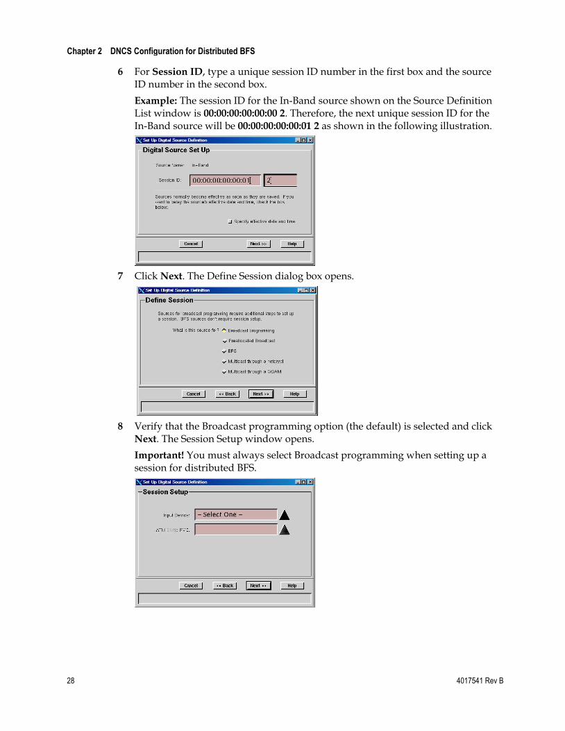
6 For Session ID, type a unique session ID number in the first box and the source ID number in the second box.
Example: The session ID for the In-Band source shown on the Source Definition List window is 00:00:00:00:00:00 2. Therefore, the next unique session ID for the In-Band source will be 00:00:00:00:00:01 2 as shown in the following illustration.
7 Click Next. The Define Session dialog box opens.
8 Verify that the Broadcast programming option (the default) is selected and click Next. The Session Setup window opens.
Important! You must always select Broadcast programming when setting up a session for distributed BFS.
Set Up CF Sessions for the Additional BFS QAM
4017541 Rev B 29
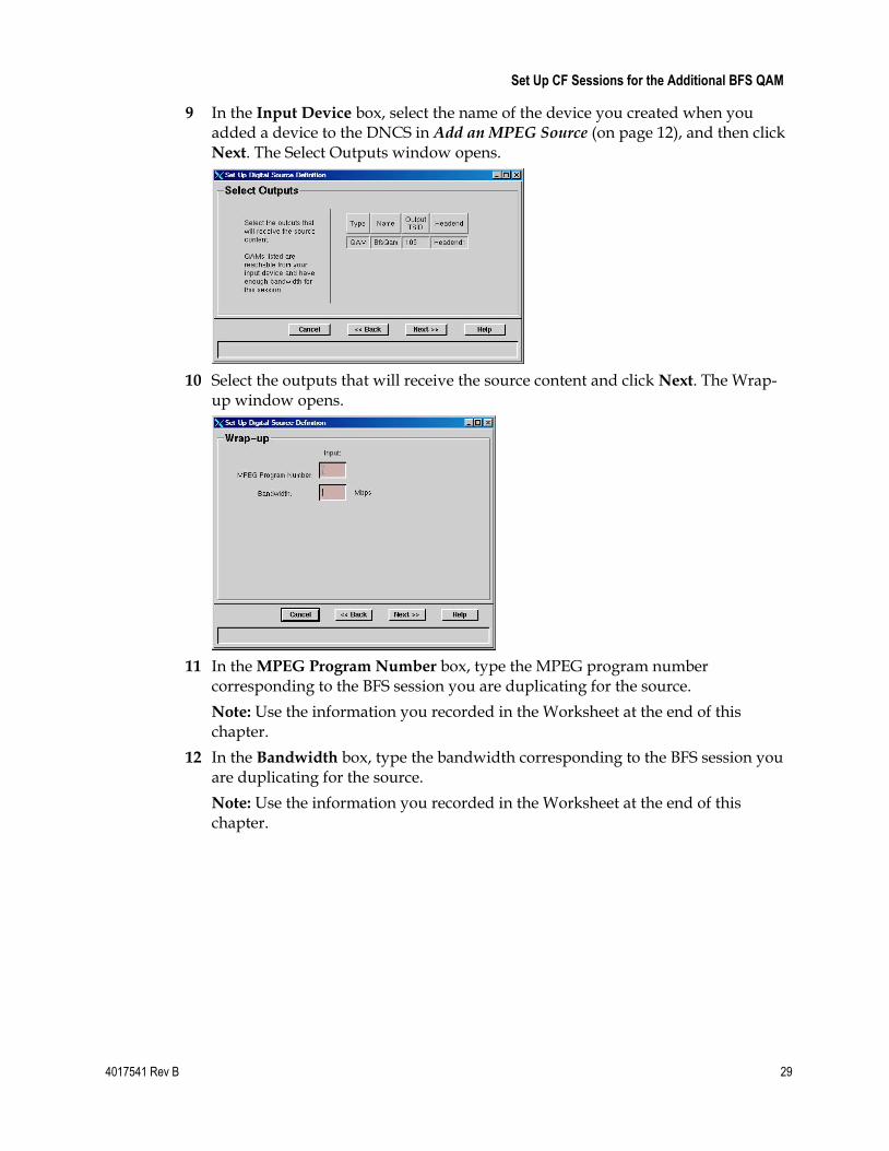
9 In the Input Device box, select the name of the device you created when you added a device to the DNCS in Add an MPEG Source (on page 12), and then click Next. The Select Outputs window opens.
10 Select the outputs that will receive the source content and click Next. The Wrap-up window opens.
11 In the MPEG Program Number box, type the MPEG program number corresponding to the BFS session you are duplicating for the source.
Note: Use the information you recorded in the Worksheet at the end of this chapter.
12 In the Bandwidth box, type the bandwidth corresponding to the BFS session you are duplicating for the source.
Note: Use the information you recorded in the Worksheet at the end of this chapter.

Chapter 2 DNCS Configuration for Distributed BFS
30 4017541 Rev B
13 Click Next. The Save Source Definition dialog box opens.
14 Click Save. The DNCS saves the source definition, starts the session, and returns to the Source Definition List window.
15 Close the Source Definition List window and return to the Source List window.
16 Repeat steps 5 to 15 for each BFS source; then go to step 17.
17 Close the Source List window and return to the DNCS Administrative Console.
18 Go to Add a New OSM Source, Source Definition, and Session (on page 31).
Add a New OSM Source, Source Definition, and Session
4017541 Rev B 31
Add a New OSM Source, Source Definition, and Session
1 On the DNCS tab of the DNCS Administrative Console, select the System
Provisioning tab.
2 Click Source. The Source List window opens.
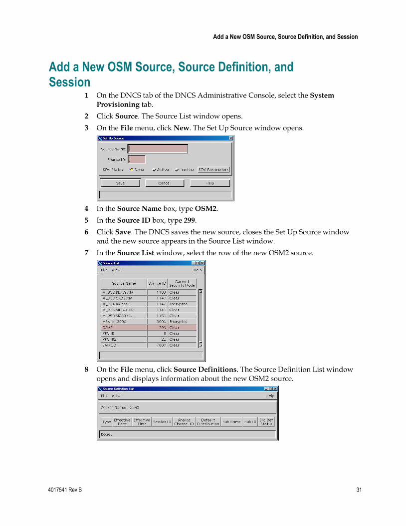
3 On the File menu, click New. The Set Up Source window opens.
4 In the Source Name box, type OSM2.
5 In the Source ID box, type 299.
6 Click Save. The DNCS saves the new source, closes the Set Up Source window and the new source appears in the Source List window.
7 In the Source List window, select the row of the new OSM2 source.
8 On the File menu, click Source Definitions. The Source Definition List window opens and displays information about the new OSM2 source.

Chapter 2 DNCS Configuration for Distributed BFS
32 4017541 Rev B
9 On the File menu, click New Digital. The Set Up Digital Source Definition window opens and displays the Digital Source Set Up area.
10 For the Session ID, type all zeros in the left box, and then type 299 in the right box.
Example: Type 00:00:00:00:00:01 299.
11 Click Next. The Define Session area of the window appears.

Add a New OSM Source, Source Definition, and Session
4017541 Rev B 33
12 Select the Broadcast programming option and click Next. The Session Setup area of the window appears.
13 In the Input Device box, select the correct MUX device, and then click Next. The Output Selection Policy area of the window appears.
14 Select the outputs that will receive the source content and click Next. The Wrap-up window opens.
15 In the MPEG Program Number box, type the MPEG program number corresponding to the BFS session you are duplicating for the source.
Note: Use the information you recorded in the Worksheet at the end of this chapter.

Chapter 2 DNCS Configuration for Distributed BFS
34 4017541 Rev B
16 In the Bandwidth box, type the bandwidth corresponding to the BFS session you are duplicating for the source.
Note: Use the information you recorded in the Worksheet at the end of this chapter.
17 Click Next. The Save Source Definition area of the window appears.
18 Click Save. The system saves your source definition and session, closes the Set Up Digital Source Definition window, and returns to the Source Definition List window.
19 From the Source Definition List window, click the File menu and select Close.
20 From the Source List window, click the File menu and select Close. The DNCS Administrative Console returns to the forefront.
21 Do you need to add an additional BFS QAM?
If yes, repeat the steps in Add Another BFS QAM to the DNCS (on page 16).
If no, your next step is to enable CVT downloads on the DNCS. Go to Enabling CVT Downloads on the DNCS (on page 37) for instructions on how to enable CVT downloads.

Worksheet
4017541 Rev B 35
Worksheet In this chapter you verify the existing session information of the specific BFS QAMs for which you want to build additional CF sessions. Use this worksheet to record the session IDs, MPEG program numbers, QAM names, and bandwidths of the existing sessions.
Important! If your system requires OSM Automux, record 00:00:00:00:00:00 199 as the session ID for the OSM session.
QAM Name Session ID Bandwidth MPEG Program Number

4017541 Rev B 37
Introduction
This chapter describes the recommended method for enabling CVT downloads in a network with BFS QAMs that are each operating at the same (overlapping) or at different (non-overlapping) frequencies.
3 Chapter 3 Enabling CVT Downloads on the DNCS
In This Chapter
Overview ................................................................................................ 38
Confirming That All DNCS Processes Are Running ....................... 39
Adding OSM Entries to the DNCS .profile File ................................ 41
Gather Information for the osmAutoMux.cfg File ........................... 42
Gather Information for Your OSM Configuration File .................... 48
Review Record Layout Examples ....................................................... 50
Configuring the osmAutoMux.cfg File .............................................. 51
Removing OSM Entries From the DNCS .profile userid File ......... 53
Testing the Distributed BFS Configuration ....................................... 54

Chapter 3 Enabling CVT Downloads on the DNCS
38 4017541 Rev B
Overview The CVT download method loads client software onto Explorer® set-tops at a speed more than twice as fast as the previous Operating System Manager (OSM) download method.
If you are familiar with the OSM method, keep in mind that the CVT method works a little differently. For example, the CVT method does not use the carousels created and managed by BFS. Instead, the OSM process creates and manages its own carousel for the delivery of images identified in the CVT table. In addition, specific to a distributed BFS configuration, the secondary QAMs use continuous feed sessions to distribute the BFS and OSM data to the secondary QAMs.
Time To Complete
Configuring the CVT download method can take up to two hours to complete.
Add an MPEG Source
If you have not already added one, your next step is to add an MPEG source to its corresponding QAM on the DNCS. See Add an MPEG Source (on page 12) for the instructions.
After you add the MPEG source to its corresponding QAM on the DNCS, your next step is to verify that all DNCS processes are running. Go to Confirming That All DNCS Processes Are Running (on page 39).

Confirming That All DNCS Processes Are Running
4017541 Rev B 39
Confirming That All DNCS Processes Are Running 1 On the DNCS Administrative Console Status window, click Monitor in the
DNCS area.
Result: The DNCS Control window opens.
Note: Some processes restart automatically in response to an error. If this happens, the status indicator cycles through red, yellow, and green as the process shuts itself down, restarts, and then becomes active. If a process remains in a red or yellow working state, this indicates that the process is not functioning properly.
2 After allowing the system to cycle through the processes, do any of the current working states still appear with red or yellow indicators?
If an indicator appears red, go to step 3.
If an indicator appears yellow, stop here and contact Cisco Services.
If all indicators appear green, go to step 7.
3 On the DNCS Control window, select the process that appears with a red indicator.
4 From the File menu, select Start Process.
5 Did the process indicator turn green after a few moments?
If yes, continue with step 6.
If no, contact Cisco Services.

Chapter 3 Enabling CVT Downloads on the DNCS
40 4017541 Rev B
6 Repeat steps 3 through 5 for each process that has a red status indicator. Then, continue with step 7.
7 Do all distributed BFS QAMs use the same frequency as the primary or local BFS QAM?
If yes, go to step 8.
If no, you must use the OSM Automux configuration. Go to Adding OSM Entries to the DNCS .profile File (on page 41).
8 Do all BFS QAMs, including the primary BFS QAM, use the same program number for the OSM session?
If yes, you do not need the OSM Automux configuration. Go to Testing the Distributed BFS Configuration (on page 54).
If no, you must use the OSM Automux configuration. Go to Adding OSM Entries to the DNCS .profile File (on page 41).

Adding OSM Entries to the DNCS .profile File
4017541 Rev B 41
Adding OSM Entries to the DNCS .profile File If your configuration requires the OSM Automux file, your next step is to add the following two OSM entries to the DNCS .profile file as described in this section:
OSM_AUTOMUX=y
export OSM_AUTOMUX
Important:
You must have a working knowledge of vi or another text editor to edit this file.
When using the OSM Automux configuration, CVT is no longer inserted on all Cisco QAMs. CVT is only inserted on the QAMs listed in the osmAutoMux.cfg file. Those QAMs that no longer carry CVT should be rebooted to clear out the old CVT.
1 Open an xterm window on the DNCS.
2 Type cd /export/home/dncs and press Enter to change to the dncs directory.
3 Type cp .profile .profile.TODAYSDATE and press Enter.
Example: If today's date is May 31, 2007, type cp.profile .profile.053107
4 Open the .profile file in a text editor.
5 Go to the last empty line in the file and add the following two commands on separate lines:
OSM_AUTOMUX=y
export OSM_AUTOMUX
6 Save the changes to the file and exit the editor. The system returns to the dncs prompt.
7 Close all open windows in all environments.
8 On the Solaris toolbar, click the Exit button. The system logs you out and closes all open windows; then, the DNCS Login window opens with the welcome message.
9 Type the user name and press Enter. The password prompt appears.
10 Type the password and press Enter. The system activates the .profile changes.
11 Using the mouse, place the cursor anywhere on the DNCS desktop, and then click the middle mouse button. A menu appears with a list of options.
12 Click Administrative Console to open the DNCS Administrative Console and the Status windows.
13 Your next step is to gather information for the osmAutoMux.cfg file. Go to Gather Information for the osmAutoMux.cfg File (on page 42).

Chapter 3 Enabling CVT Downloads on the DNCS
42 4017541 Rev B
Gather Information for the osmAutoMux.cfg File You must describe the network topology to the OSM to support bootloader in an Automux environment. To do this, you enter the following types of records in the /dvs/dvsFiles/OSM/osmAutoMux.cfg file.
QAM (QAM transport stream ID to headend mapping)
HUB (hub ID to headend mapping)
SESS (session to headend mapping)
This section provides procedures for gathering all of the information you need to build your osmAutoMux.cfg file. You can record the information you gather in the worksheets provided later in this chapter or in your own worksheets.
Obtaining Output TSIDs
Complete these steps to find and record the output Transport Stream ID (TSID) information required for the osmAutoMux.cfg file.
1 From the DNCS Administrative Console, click the Network Element Provisioning tab.
2 Click QAM. The QAM List window opens.
3 Using the information in the QAM List window, record the name and the output TSID for each of the following QAM types in the order presented.
Primary (local) BFS QAM for the primary headend
Video QAMs for the primary headend
Secondary BFS QAM for the secondary headend
Video QAMs for the secondary headend
BFS QAM for an additional headend (if applicable)
Video QAMs for an additional headend (if applicable)

Gather Information for the osmAutoMux.cfg File
4017541 Rev B 43
Important! You might have multiple rows for each output on a BFS QAM. For example, if you are using an MQAM as a BFS QAM, the QAM List window contains a separate row for each output on the MQAM. Record the output TSID for each output on the MQAM (4 outputs).
4 If you have additional headends, continue the same pattern described in step 3 to record the QAM Name and Output TSID for the BFS QAM and all video QAMs for each headend.
5 When you have finished recording the output TSIDs for the BFS QAMs and video QAMs in each headend, select File and choose Close to close the QAM List window.
Obtaining Headend IDs
Complete these steps to obtain headend IDs. For the primary BFS QAM in the primary headend, you must query the database for the real headend ID. For your other headends, use an arbitrary but unique number for each headend ID.
1 From an xterm window on the DNCS, log on to the DNCS as root.
2 Type the following command and press Enter.
dbaccess dncsdb -
Result: The message Database selected appears.
3 Type the following command and press Enter.
select * from headend
Result: An output similar to the following appears.
he_id he_name he_em_hostname optimctrl
7 MFG TEST 3
1 row(s) retrieved.
4 Record the value under he_id as the headend ID for the primary BFS QAM and the video QAMs in the primary headend in the QAM Record worksheet.
5 Press Ctrl+C to exit the database.
6 Type exit to close the xterm window.
7 For your other headends, use an arbitrary but unique number for each headend ID. For example, you could assign a headend ID of 2 to the secondary BFS QAM and all video QAMs in the secondary headend. You could assign a headend ID of 3 to the tertiary BFS QAM and all video QAMs in the tertiary headend, and so on. Record the values you devise in the QAM Record worksheet.

Chapter 3 Enabling CVT Downloads on the DNCS
44 4017541 Rev B
Obtaining Hub IDs
Complete these steps to find and record the Hub ID information required for the osmAutoMux.cfg file.
1 From the DNCS Administrative Console, click the Network Element
Provisioning tab.
2 Click Hub. The Hub List window opens.
3 Using the information in the Hub ID column, record the correct Hub ID associated with each Headend ID that you recorded earlier.
Obtaining OSM Information
Complete these steps to find and record the Session ID information required for the osmAutoMux.cfg file.
1 From the DNCS Administrative Console, click the Utilities tab.
2 Click Session List. The Session Filter window opens.
3 Click the Data QAM from the Session Filter list and then click Display QAM
Sessions. The session data for the QAM you selected appears.
4 Click the VASP Name column heading to sort the session list by VASP type. The OSM sessions should sort to the top of the window. If not, scroll to the group of OSM sessions.
5 Using the information in the Session ID column of the Session List window, record the correct Session ID associated with each BFS QAM for each headend.
6 For each BFS QAM, record the (real) headend ID associated with the headend for each of the BFS QAM feeds (in the primary headend).

Gather Information for the osmAutoMux.cfg File
4017541 Rev B 45
QAM Worksheet
Complete the following worksheet before editing the osmAutoMux.cfg file. The QAM Name column is provided to help you ensure your record information for all necessary QAMs. You do not have to enter the name of your QAM in the OSM Configuration file.
QAM Name Output TSID Headend ID

Chapter 3 Enabling CVT Downloads on the DNCS
46 4017541 Rev B
Hub Worksheet
Complete this worksheet to record the correct Hub ID to Headend ID associations.
Headend ID Hub ID

Gather Information for the osmAutoMux.cfg File
4017541 Rev B 47
Session Worksheet
Complete this worksheet to record the correct OSM session information for each BFS QAM.
Note: The OSM session ID for the BFS QAM in the primary headend is 00:00:00:00:00:00 199.
OSM Session MAC Address
OSM Session ID Headend ID
00:00:00:00:00:00 199
Chapter 3 Enabling CVT Downloads on the DNCS
48 4017541 Rev B
Gather Information for Your OSM Configuration File
Gather the following information for each data QAM in your system. Record this information in the worksheet on the following page.
Output TSID—To find the numeric output transport stream ID for the QAM, open the Set Up QAM window by clicking QAM from the Network Element Provisioning tab.
Headend ID—Write down the exact headend ID for the "real" headend QAM that is included in your system. This Headend ID will be repeated in each of the three record types you enter in the osmAutoMux.cfg file (QAM, HUB, and SESS records).
Notes:
If arbitrary QAMs are set up in your system, choose arbitrary numbers to make tracking the configuration easier. This number does not have to match the actual headend ID. Each QAM must have its own unique number.
If real QAMs are set up in your system, you must enter the actual headend ID for the headend device.
Session MAC Address—Write down the 12-character HEX MAC address without the colons (:). The session MAC Address is determined by the value that was used when sessions were built.
Session ID—Session IDs range from 2 to 22. For the OSM session, the session ID for the primary OSM session is 199. The session ID for the secondary OSM session is 299.
Hub ID—To find the numeric Hub ID, go to the Hub Summary window by clicking Hub under the Element Provisioning tab.

Gather Information for Your OSM Configuration File
4017541 Rev B 49
OSM Worksheet
Note: The QAM column is provided to help you ensure you record information for all necessary QAMs. You do not have to enter the name of your QAM in the OSM Configuration file.
QAM Output TSID Headend ID Session MAC Address Session ID Hub ID

Chapter 3 Enabling CVT Downloads on the DNCS
50 4017541 Rev B
Review Record Layout Examples Review the sample record layouts in this section. Note that the record tags (QAM, HUB, and SESS) must always begin in the first column. Each field must be separated by a pipe ( | ).
QAM Record Layout QAM|OUTPUT TSID|HEADEND ID
Example:
QAM|101|100
HUB Record Layout HUB|HUB ID|HEADEND ID
Example:
HUB|1|100
SESS Record Layout SESS|SESSMAC|SESSID|HEADEND ID
Example:
SESS|000000000002|199|100
Sample File
This sample file describes a simple system with two headends identified as 100 and 200.
Sample Features of This Sample System
QAM|101|100
QAM|203|200
Two QAMs—One with an output transport stream ID of 101 in headend 100 and the other with an output transport stream ID of 203 in headend 200
HUB|1|100
HUB|6|200
Two hubs—Hub ID 1 is in headend 100 and Hub ID 6 is in headend 200
SESS|000000000000|199|100
SESS|000000000001|299|200
Two sessions for the OSM—Session ID 00:00:00:00:00:00 199 is for headend 100 and session ID 00:00:00:00:00:01 299 is for headend 200

Configuring the osmAutoMux.cfg File
4017541 Rev B 51
Configuring the osmAutoMux.cfg File Using the information you recorded in your worksheets, configure the dvs/dvsFiles/OSM/osmAutoMux.cfg file. Note that the records tags (QAM, HUB, and SESS) must always begin in column 1. Each field must be separated by |.
QAM Record Layout QAM|OUTPUT TSID|HEADEND ID
HUB Record Layout HUB|HUB ID|HEADEND ID
SESS Record Layout SESS|SESSMAC|SESSID\HEADEND ID
Complete these steps to configure the /dvs/dvsFiles/OSM/osmAutoMux.cfg file.
1 In an xterm window on the DNCS, type cd /dvs/dvsFiles/OSM and press Enter
to change to the OSM directory.
2 Open the osmAutoMux.cfg file in a text editor. A new osmAutoMux.cfg file opens and the cursor moves to the upper left corner of the window.
3 Type the record entries for the QAMs, HUBs and SESSs using the correct format for each record type.
Notes:
All the records must begin in column 1 and end with a line feed character.
The order of the records is not important. However, to make it easier to maintain this file, Cisco recommends that you group all QAM records together, all HUB records together, and all SESS records together.
You can add comments to specific records in the file using the # sign.
Example: Identify the primary BFS QAM I n the file using the following comment:
QAM|100|1 #Primary BFS QAM for Primary HE
You can add comments to separate groups of records in the file.
Example: Identify the beginning of the HUB records for a specific headend using the following comment:
# HUBS IN HEADEND 1
HUB|7|1

Chapter 3 Enabling CVT Downloads on the DNCS
52 4017541 Rev B
4 When you finish typing the record entries, save the text file and exit the text editor.
Note: In Automux Mode, the OSM reads the configuration from the /dvs/dvsFiles/OSM/osmAutoMux.cfg ASCII text file only once at startup.
Important! If you make any changes to this file, you must stop and restart the OSM process.
5 Go to Removing OSM Entries From the DNCS .profile userid File (on page 53).

Removing OSM Entries From the DNCS .profile userid File
4017541 Rev B 53
Removing OSM Entries From the DNCS .profile userid File
After verifying your configuration, remove the following two OSM entries from the DNCS .profile userid file:
OSM_AUTOMUX=y
export OSM_AUTOMUX
Removing OSM Entries from the DNCS .profile userid File 1 On the DNCS tab of the DNCS Administrative Console, click the Utilities tab.
2 Click xterm. An xterm window opens.
3 Type cd /export/home/dncs and press Enter to change to the dncs directory.
4 Type cp .profile .profile.TODAYSDATE and press Enter.
Example: If today's date is May 31, 2007, type cp.profile .profile.053107
5 Open the .profile file in a text editor.
6 Go to the line that contains the OSM_AUTOMUX=y entry and delete the line.
7 Go to the line that contains the export OSM_AUTOMUX entry and delete the line.
8 Save the changes to the file and exit the text editor. The system returns to the dncs prompt.
9 Type exit to close the xterm window.

Chapter 3 Enabling CVT Downloads on the DNCS
54 4017541 Rev B
Testing the Distributed BFS Configuration Your next step is to verify that you successfully set up your distributed BFS configuration.
To verify that you have successfully set up your distributed BFS configuration, you must test the operation of the set-tops in your system to ensure that they are receiving data from all the BFS QAMs.
Note: Perform this test for each BFS QAM on each hub.
1 Unplug a test set-top on a remote headend and plug it back in.
2 Wait for about 3 minutes for the set-top to reboot.
3 Using your remote control, buy an impulse pay-per-view (IPPV) movie.
4 Tune to all digital channels.
5 Verify that 7 days of IPG information is available.
6 Stage a set-top.
7 Is the set-top operating normally?
If yes, you have successfully completed this procedure.
If no, contact Cisco Services for assistance.

4017541 Rev B 55
Introduction
This chapter contains the instructions for disabling OSM Automux only. For example, if you move from a non-overlapping configuration to an overlapping configuration, you may want to disable OSM Automux.
If you are using OSM Automux and you want to remove the entire distributed BFS configuration from your system, you must complete this chapter and then go to Removing the Distributed BFS Configuration From the DNCS (on page 63) to complete the removal process.
4 Chapter 4 Disabling OSM Automux
In This Chapter
Before You Begin ................................................................................... 56
Checking BFS QAM Frequencies ........................................................ 57
Verify Program Numbers .................................................................... 58
Removing OSM Entries From the DNCS .profile userid File ......... 61
Bouncing the OSM Process .................................................................. 62

Chapter 4 Disabling OSM Automux
56 4017541 Rev B
Before You Begin Your first step to disable OSM Automux is to confirm that all DNCS processes are running. See Confirming That All DNCS Processes Are Running (on page 39) for the procedure.
Also, ensure your system meets both of the following requirements:
The distributed BFS QAMs use the same frequency as the primary BFS QAM.
All BFS QAMs use the same program number for the OSM session.
Complete the following procedures to verify both of these requirements are met.

Checking BFS QAM Frequencies
4017541 Rev B 57
Checking BFS QAM Frequencies Complete these steps to verify all distributed BFS QAMs use the same frequency as the primary BFS QAM.
1 On the DNCS Administrative Console, click the DNCS tab and then the Network Element Provisioning tab.
2 Click QAM. The QAM List window opens.
3 Select the row corresponding to the primary BFS QAM.
4 Note the frequency in the Channel Center Frequency column and record the frequency.
Primary BFS QAM Frequency: _________________
5 From the QAM List, verify that the frequency for each of your secondary BFS QAMs matches the frequency you recorded in step 4.
6 When you have finished verifying frequencies, close the QAM List window.
7 Did the frequencies for every secondary BFS QAM match the frequency for the primary BFS QAM?
If yes, continue to the next check, Verify Program Numbers (on page 58).
Important! The frequencies must be the same for all BFS QAMs, including the local BFS QAM, to meet this requirement.
If no, do not remove OSM Automux.

Chapter 4 Disabling OSM Automux
58 4017541 Rev B
Verify Program Numbers Complete these steps to verify that all BFS QAMs use the same program number for the OSM session.
Finding Program Numbers on Systems Using a BFS BIG 1 On the DNCS Administrative Console, click the DNCS tab, and then click the
Network Element Provisioning tab.
2 Click BIG. The BIG List window opens.
3 Select the headend corresponding to your primary BFS QAM.
4 On the File menu, click Open. The Set Up BIG window opens.
5 Click PAT Configuration. The BIG PAT window opens.
6 Check and record the Program Number for the OSM session in the BIG PAT table.
7 Program Number for OSM Session: ____________
8 Close the BIG PAT window, the Set Up BIG window, and the BIG List window.
9 Go to Verifying Program Numbers (on page 60).

Verify Program Numbers
4017541 Rev B 59
Finding Program Numbers on Systems Using Direct ASI 1 On the DNCS Administrative Console, click the Application Interface Modules
tab.
2 Click BFS Admin. The Site DNCS BFS Administration window opens.
3 On the Hosts tab, double-click dncsatm. The Set Up BFS Host window opens.
4 Click PAT Configuration. The Inband Data PAT window opens.
5 Check and record the Program Number for the OSM session in the Inband Data PAT table.
Program Number for OSM Session: ____________

Chapter 4 Disabling OSM Automux
60 4017541 Rev B
6 Close the Inband Data PAT window, the Set Up BFS Host window, and the Site DNCS BFS Administration window.
7 Go to Verifying Program Numbers, next in this document.
Verifying Program Numbers 1 On the DNCS Administrative Console, click the DNCS tab and then the System
Provisioning tab.
2 Click Source. The Source List window opens.
3 Select the row corresponding to the secondary OSM source. If you followed this guide to create this source, the source is named OSM2.
4 On the File menu, click Source Definitions. The Source Definition List window opens.
5 Complete the following steps for each row in the list.
a Double-click the row to open the Set Up Digital Source Definition window.
b Note the Program Number.
6 After you have verified the source definition for each row in the Source Definition List window, close the Set Up Digital Source Definition window, the Source Definition List, and the Source List window.
7 Were all the program numbers the same for the OSM session?
If yes, go to Removing OSM Entries From the DNCS .profile userid File (on page 53).
Important! The program numbers must be the same for all BFS QAMs, including the local BFS QAM, to meet this requirement.
If no, do not remove OSM Automux.

Removing OSM Entries From the DNCS .profile userid File
4017541 Rev B 61
Removing OSM Entries From the DNCS .profile userid File
After verifying your configuration, remove the following two OSM entries from the DNCS .profile userid file:
OSM_AUTOMUX=y
export OSM_AUTOMUX
Removing OSM Entries from the DNCS .profile userid File 1 On the DNCS tab of the DNCS Administrative Console, click the Utilities tab.
2 Click xterm. An xterm window opens.
3 Type cd /export/home/dncs and press Enter to change to the dncs directory.
4 Type cp .profile .profile.TODAYSDATE and press Enter.
Example: If today's date is May 31, 2007, type cp.profile .profile.053107
5 Open the .profile file in a text editor.
6 Go to the line that contains the OSM_AUTOMUX=y entry and delete the line.
7 Go to the line that contains the export OSM_AUTOMUX entry and delete the line.
8 Save the changes to the file and exit the text editor. The system returns to the dncs prompt.
9 Type exit to close the xterm window.

Chapter 4 Disabling OSM Automux
62 4017541 Rev B
Bouncing the OSM Process After you have updated the DNCS .profile userid file, your next step is to bounce (stop and restart) the OSM process.
1 If the DNCS Control window is not already open, click the Control button in the DNCS area of the DNCS Administrative Console Status window.
Result: The DNCS Control window opens.
2 From the list of processes, click osm.
3 Click the Process menu and then select Stop Process. A confirmation message appears.
4 Click Yes to stop the OSM process. This causes the indicator next to OSM to turn red.
5 From the list of processes, click osm.
6 From the Process menu, click Start Process. The indicator next to osm turns green when the osm has successfully restarted.
4017541 Rev B 63
Introduction
This chapter provides instructions for removing a Distributed BFS configuration from the DNCS.
Important! If you are using OSM Automux (a non-overlapping configuration), ensure you have completed the procedures in Disabling OSM Automux (on page 55) before you complete the procedures in this chapter.
5 Chapter 5 Removing the Distributed BFS Configuration From the DNCS
In This Chapter
Removing the OSM Source, Source Definition, and Session .......... 64
Removing CF Sessions for the Additional BFS QAMs .................... 65
Removing MPEG Sources .................................................................... 66

Chapter 5 Removing the Distributed BFS Configuration From the DNCS
64 4017541 Rev B
Removing the OSM Source, Source Definition, and Session
1 On the DNCS Administrative Console, click the DNCS tab if it is not already in the forefront.
2 Click the System Provisioning tab.
3 Click Source. The Source List window opens.
4 Highlight the OSM carousel (OSM2). Then, click the File menu and select Source
Definitions. The Source Definition List opens.
5 Highlight the source definition to be deleted. Then, click the File menu and select Delete.
6 A confirmation window opens. Click Yes.
7 Close the Source Definition List window.
8 Keep the Source List window open and go to Removing CF Sessions for the Additional BFS QAMs (on page 65).

Removing CF Sessions for the Additional BFS QAMs
4017541 Rev B 65
Removing CF Sessions for the Additional BFS QAMs
1 From the Source List window, click the Source ID column twice to sort the source IDs from the lowest to the highest number.
2 Click to highlight the row with the source name and source ID you want to delete for the BFS QAM CF Session.
3 Click the File menu and select Source Definitions. The Source Definition List window opens and lists the available source definition(s) with their session IDs for the source you selected.
4 Click to highlight the session that you want to remove from the BFS QAM that you are planning to delete.
5 Click the File menu and select Delete.
6 A confirmation window opens. Click Yes.
7 Close the Source Definition List window.
8 Repeat steps 2 through 7 for each CF session you want to delete.

Chapter 5 Removing the Distributed BFS Configuration From the DNCS
66 4017541 Rev B
Removing MPEG Sources 1 On the DNCS Administrative Console, click the DNCS tab.
2 Click the Network Element Provisioning tab.
3 Click QAM. The QAM List window opens.
4 Highlight the additional BFS QAM you want to delete. Then, click the File menu and select Delete.
5 A confirmation window opens. Click Yes.
6 Repeat steps 4 and 5 for any additional BFS QAMs you need to delete.
7 Close the QAM List window.

4017541 Rev B 67
If You Have Questions
If you have technical questions, call Cisco Services for assistance. Follow the menu options to speak with a service engineer.
Access your company's extranet site to view or order additional technical publications. For accessing instructions, contact the representative who handles your account. Check your extranet site often as the information is updated frequently.
6 Chapter 6 Customer Information

Cisco Systems, Inc. 5030 Sugarloaf Parkway, Box 465447 Lawrenceville, GA 30042
678 277-1120 800 722-2009
www.cisco.com
This document includes various trademarks of Cisco Systems, Inc. Please see the Notices section of this document for a list of the Cisco Systems, Inc. trademarks used in this document. Product and service availability are subject to change without notice.
© 2007, 2012 Cisco and/or its affiliates. All rights reserved. May 2012 Printed in USA
Part Number 4017541 Rev B