distributed by: distributed b - siata valve controllers...use and maintenance manual aqua timer plus...
TRANSCRIPT

Aqua Timer Plus - 1/34
USE AND MAINTENANCE MANUAL
AQUA TIMER PLUS
y:Distributed b
37 Tannery Lane#06-08 Tannery HouseSingapore 347790Tel: +65 6741 2994 • Fax: +65 6741 2995
S.I.A.T.A Asia Pacific Pte LtdDistributed by:
www.siata.com.sg

Aqua Timer Plus - 2/34
EC DECLARATION OF CONFORMITY
Producer SIATA S.r.l.
Declares that the following material:
PN AT-PLUS2/05 Description
AQUA TIMER PLUS Conforms to the essential pre-requisites of the following DIRECTIVES: Electromagnetic Compatibility 89/336/CEE, 93/68/CEE
Low Voltage 73/23/CEE, 93/68/CEE
The fulfilment of the following regulations has been verified:
EN 50081-1 General Regulation on Emissions – part 1 residential, commercial and light industry environment
EN 50082-1 General Regulation on Immunity – part 1 residential, commercial and light industry environments
SIATA S.R.L. has a Quality System which conforms to the requirements of the
regulation: ISO 9001/UNI EN ISO 9001-ed. 1994 (Certificate n°95.022 SGS ICS )
Managing Director
LUIGI FERRALI
Aqua Timer Plus - 3/34
Index
1 – BASIC CHARACTERISTICS .................................................................................................................................. 4
2 – TECHNICAL DATA .................................................................................................................................................. 5
3 – EXPLANATION OF THE LEDS AND OF THE KEYS ........................................................................................ 6
4 – STATES OF VISUALISATION OF THE DISPLAY ............................................................................................. 7
5 – GENERAL .................................................................................................................................................................. 7 5.1 – PACKAGING AND STORAGE ................................................................................................................................ 7 5.2 – INSTALLATION ..................................................................................................................................................... 7 5.3 – ELECTRICAL CONNECTIONS ............................................................................................................................... 8 5.4 – PROTECTION DEVICES ......................................................................................................................................... 8
6 – INSTRUCTIONS FOR USE ...................................................................................................................................... 9 6.1 – TURNING ON ......................................................................................................................................................... 9 6.2 – PROGRAMMING OF THE OPERATIVE MODALITIES ........................................................................................... 9
6.2.1 – LLL1 – LL–1 – One single column with start by time ................................................................................... 11 6.2.2 – LLL1 – LL–2 – One single column with start by volume. ............................................................................. 12 6.2.3 - LLL1 – LL–3 – One single column with mixed time / volume start. .............................................................. 14 6.2.4 – LLL2 – LL–1 – A duplex column with start by time. ..................................................................................... 16 6.2.5 – LLL2 – LL–2 – One duplex column with start by volume. ............................................................................ 18 6.2.6 – LLL2 – LL–3 – One duplex column with mixed time / volume start.............................................................. 20
6.3 – PROGRAMMING CODES .................................................................................................................................... 22 6.3.1 – Access to the programming codes ................................................................................................................. 22 6.3.2 – List of programming codes and their meaning ............................................................................................. 22
6.4 – PROGRAMMING OF THE RESERVE .......................................................................................................................... 23 6.5 – REMOTE START ..................................................................................................................................................... 24 6.6 – PROGRAMMING OF THE LITRE COUNTER DIVIDER ( PRESCALER ) ........................................................................... 24 6.7 – CALCULATION OF THE CYCLIC CAPACITY OF A SYSTEM ........................................................................................ 25 6.8 – FUNCTIONALITY OF THE REGENERATION CYCLE, FLAGS 1CL AND 2CL. ............................................................... 26 6.9 – MANAGEMENT OF THE ALARM OF END OF REGENERATIVE AUTONOMY ................................................................. 28 6.10 – PUTTING INTO SERVICE ....................................................................................................................................... 28 6.11 – CONNECTIONS ..................................................................................................................................................... 29 6.12 – MANAGEMENT OF THE INHIBIT SIGNAL. FLAG 0DL. ............................................................................................ 29
7 – WHAT TO DO IF … ................................................................................................................................................ 31 7.1 - ... AQUA TIMER PLUS DOES NOT COME ON ? .......................................................................................................... 31 7.2 - ... THE MOTORS OF THE DISTRIBUTORS DO NOT STOP ? ........................................................................................... 31 7.3 - ... THERE IS NO CURRENT TO THE UTILISERS? ......................................................................................................... 31 7.4 - ... AQUA TIMER PLUS WORKS IN AN IRREGULAR WAY? .......................................................................................... 31
APPENDIX A (GENERAL ELECTRICAL CONNECTIONS) ................................................................................. 32
APPENDIX B (ELECTRICAL CONNECTIONS FOR THE SINGLE DISTRIBUTOR) ...................................... 33
APPENDIX C (ELECTRICAL CONNECTIONS FOR THE DUPLEX DISTRIBUTOR) .................................... 34

Aqua Timer Plus - 4/34
1 – BASIC CHARACTERISTICS Aqua Timer Plus is dedicated to the control of a SIATA multi-port valve for the realisation of water softening systems, working on the principle of ionic exchange resins. Aqua Timer Plus can control a hydraulic distributor which, with one or two SIATA valves, forms an electrical/hydraulic command unit for single or duplex systems. When Aqua Timer Plus is programmed in a duplex mode, it is possible to activate a particular regeneration cycle, which has a stand-by position at the start of the regeneration. Aqua Timer Plus automatically calculates the volume of treatable water based on the following parameters: the hardness of the water the volume of the tank the capacity of the exchange of the resins used
The regeneration cycle is entirely programmable and may be run in three different ways: by time (the programmed time running out sets off the regeneration) by volume (the programmed volume running out sets off the regeneration) mixed (this is a combination of the first two) manually by an external signal (remote starter) It is also possible, by pressing the key Reset to cancel a regeneration in progress, or to jump one or more phases by pressing the key Regener during the stop phase. Aqua Timer Plus makes it possible to use an outlet which is activated during the second phase of the regeneration cycle (phase 2C normally used for having the regenerants moved along the resin), which may be used to control the supply of an electrolytic cell for chlorine or any other electrical controller. Aqua Timer Plus is equipped with a counter of the regenerations which may be carried out with the salt introduced into the system; the controller will emit an alarm when it is the right time to restore the salt level. Aqua Timer Plus may be connected to a computer via RS232 using the correct cable serial cod. 881-1, so as to be able to acquire and then analyse the progress of the work parameters. Aqua Timer Plus is equipped with a buffer battery which allows for the work parameters to be retained in the memory should the electricity current fail. Aqua Timer Plus is equipped with an EEPROM memory, on which the programmed data is memorised, with the capacity to retain data for over 10 years. Aqua Timer Plus, like all the range of SIATA controllers, conforms to the EEC Directives and is produced in the SIATA plant of Montespertoli which operates with the certified Quality System according to the regulation
ISO 9001 / UNI EN ISO 9001.
Aqua Timer Plus - 5/34
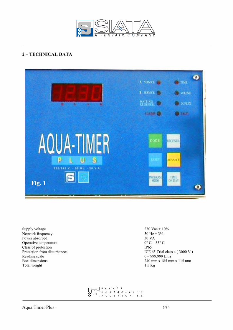
2 – TECHNICAL DATA
Supply voltage 230 Vac 10% Network frequency 50 Hz 3% Power absorbed 30 VA Operative temperature 0° C – 55° C Class of protection IP65 Protection from disturbances ICE 65 Trial class 4 ( 3000 V ) Reading scale 0 – 999,999 Litri Box dimensions 240 mm x 185 mm x 115 mm Total weight 1.5 Kg
Fig. 1

Aqua Timer Plus - 6/34
3 –LEDS AND KEYS MEANING
The tabs. 1 and 2 describe the meaning respectively of the LEDs and of the keys on the front panel of the controller, and which can be seen in fig. 1.
Tab. 1 – Functionality of the LEDs LED Meaning
A SERVICE On when column A is in service B SERVICE On when column B is in service
WAIT. REGEN. The controller waits until the programmed time for the regen. ALARM Alarm
TIME Control of the time for the start of the regeneration VOLUME Control of the volume for the start of the regeneration DUPLEX Duplex distributor in use
SALT Alarm when salt has run out TIME+VOLUME Both the LEDs on, mixed control time/volume for the regen.
Tab. 2 – Functionality of the keys Key Description
CODE Access to the programming of the work parameters through the protection code. During the programming, returns to zero the value being modified
RESET Allows for the programming to be outleted from, without memorising the last value keyed in. Pressed during the service, resets the counters of the management of salt alarm.
PROGRAM MODE Allows access to the programming functions.
REGENER. Starts up the regeneration. Pressed during the stop time, returns to zero the residual time and starts up the next phase.
ADVANCE Changes the visualisation mode of the display. In programming, increases the value being modified.
TIME OF DAY
Resetting of the local time. If the flag 1HL is programmed to 1, after the time the day of the week is set.

Aqua Timer Plus - 7/34
4 – STATES OF VISUALISATION OF THE DISPLAY The display, through the key Advance, allows the different operative states and/or data to be visualised. The LEDs A or B will indicate which to column the data visualised on the display refers.
Tab. 3 – Data visible on the display
Display Operative state/ Data visualised
Advance 1 2 . 3 0 Local time. The central dot is flashing.
Advance 0 2 . 3 0 Time programmed for the regeneration. The central dot is not flashing.
Advance d - 3 0 The programmed number of reserve regenerations (remains fixed).
Advance d d 3 0 The number of regenerations before the salt runs out (is updated).
Advance - - - - If no regeneration is in progress, 4 lines appear
1 C 2 5 If a regeneration is in progress, the progression appears.
Advance 5 . 0 0 0 Value of the residual volume.
5 – GENERAL The installation of the controller must be carried out by qualified personnel; the installation procedures must be carried out when the controller is disconnected from the electricity supply 5.1 – Packaging and storage The packaging consists of a cardboard box with a label identifying the product, carrying the following infrormation: name of producer and PN producer AT-PLUS2/05; the quick reference guide for the installation and programming may be found inside. No particular procedures are necessary for the removal of the controller from the packaging. The controller must be stored in environments with the following characteristics: Temperature of between +0°C and +55°C; Relative humidity of between 30 % and 95 %. 5.2 – Installation The controller consists of a PVC box with a cover in plexi-glass which may be opened manually, giving access to the keypad, and of a cover which may be removed by removing two screws and which gives access to the external connection terminal board. The box is covered by a certificate with the IP65 grade of protection, Aqua Timer Plus is therefore protected against infiltration of dust and direct jets of water. This protection is valid when the cover is closed, and the wiring slots are of the correct size for the cables used and are correctly assembled. If these conditions are not respected, the level of protection falls to IP40, which gives no protection against infiltration of dust and water. The back of the box is equipped with mechanical details which allow it to be wall-mounted.

Aqua Timer Plus - 8/34
5.3 – Electrical connections The electrical connection of the controller must take place conforming to the conditions stated in the diagram CE0027 shown on the attached appendix A. If the system uses a single hydraulic distributor connected with one or two valves, the relative electrical connections must conform to that indicated in the diagram CE0028 which is shown on the attached appendix B. If the system uses a duplex hydraulic distributor connected to one valve each, the relative electrical connections must conform to that indicated in the diagram CE0021 which is shown on the attached appendix C. Also follow the instructions shown in par. 6.11 on the connections. The controller is equipped with free contact outlets with the following signals.
- Dosing pump - End of cycle impulse - Impulse during phase 2 - Alarm - Regeneration in progress
Warning!! Before carrying out any installation and/or maintenance operation, check that the controller is disconnected from the power supply. The supply to the controller must take place in accordance with all that is set out in the Low Voltage directive (73/23/EEC). Aqua Timer Plus is equipped with a clip for the earth connection. 5.4 – Protection devices The controller is protected from current overloads by a 0.6A supply retardant fuse which is assembled on the front panel. It is also protected against disturbances originating from the electricity supply by filters mounted inside the controller. If the version supplied at 24 Vac is used, the fuse is 1A retardant. An Autoreset circuit intervenes automatically if Aqua Timer Plus stops functioning after particularly strong disturbances.

Aqua Timer Plus - 9/34
6 – INSTRUCTIONS FOR USE 6.1 – Turning on The controller is turned on via the main switch ON (I) - OFF (0) situated on the front panel. This switch acts on both supply conductors. The supply voltage must be 230 Vac - 50 Hz. (on demand 24 Vac – 50 Hz. ) Check the supply voltage using the adhesive labels situated on the cover of the connections. 6.2 – Programming of the operative modalities Before proceeding to the programming of Aqua Timer Plus, it must be checked that the distributor cams are positioned at the limit cycle position. If operations are to be carried out on the controller before its installation, that is without the distributor connected, the limit switch entry must be closed with a connection bridge. If this simple rule is not respected, Aqua Timer Plus will accept all the new programming, but will not be able to carry out the normal operations needed during the service. The programming will be carried out via the keypad on the front of the controller. Aqua Timer Plus has the following operative modalities:
Tab. 4 – Table of the operative modalities Code Description Cam rotation times
L L L 1 One single column 4 stop with 50 second rotation time
L L L 2 One duplex column 4 stop with 25 second rotation time
L L L 2 One duplex column and distributor with stand-by 3 stop with 25 second rotation time The selection takes place according to the sequence shown below:
Tab. 5 – Selection of the operative modalities
Display Operative state / Data visualised
Program S C - - State of access to the insertion of the programming codes
Advance S C 0 0 By using the Advance key the programming code is selected ( 0 9)
Advance S C 0 9 The code for the programming of the operative modalities
Program L L L 1 The number 1 indicates the single column
Advance L L L 2 The number 2 indicates the duplex column
If the protection code has been programmed through the programming function SC07 (see par. 6.3), the procedure described in tab. 5 varies as follows:

Aqua Timer Plus - 10/34
Tab. 6 – Selection of the operative modalities through the protection code
Display Operative state / Data visualised
Code 0 0 0 0 Key in the protection code programmed with the function SC07
Advance 0 0 0 2 Key the code on the display with the keys Advance and Code
Code S C - - State of access to the keying in of the programming codes
Advance S C 0 0 With the key Advance the programming code is selected( 0 9)
Advance S C 0 9 The code for the programming of the of the operative modality
Program L L L 1 The number 1 indicates the single column
Advance L L L 2 The number 2 indicates the duplex column
In the same way, in all the following tables where there is the sequence
Program S C - - State of access to the keying in of the programming codes
the sequence
Code 0 0 0 0 Key in the protection code programmed with the function SC07
Advance 0 0 0 2 Key the code on the display with the keys Advance and Code
Code S C - - State of access to the keying in of the programming codes
is substituted when there is a different protection code. IMPORTANT !!! To remove the protection code, set the value 0000 in the function SC07. If the protection code is forgotten, it is no longer possible to enter the programming functions. In case of need, contact the SIATA technical service. Pressing the key Program Mode after the selection shown in tab. 5, proceed to the selection of the regeneration start mode, as shown in tab. 7.
Tab. 7 – Selection of the control modality of the regeneration start
Display Operative state / Data visualised
Program L L - 1 Regeneration by time. The LED TIME comes on on the panel
Advance L L - 2 Regeneration by volume. The LED VOLUME comes on on the panel
Advance L L - 3 Mixed regeneration. The LEDs TIME and VOLUME come on on the panel

Aqua Timer Plus - 11/34
6.2.1 – LLL1 – LL–1 – One single column with start by time 6.2.1.a – Operative characteristics. In this operative modality, the regeneration starts exclusively at the programmed time, after the interval days programmed (or on the days of the week selected). No control on the volume or on the reserve is available. Control on the remote start is available, which can start up the regeneration both immediately or deferred to the programmed time based on the content of the flag 2HL. In this operative modality it is not possible to activate the cycle with the stand-by. 6.2.1.b – FLAG Programming The tab. 8 is to be used in the programming of the flag for the modality LLL1 – LL–1
Tab. 8 – Selection of the operative modality single column - time start
FLAG Display Operative state / Data visualised
Program S C - - State of access to the selection of the programming codes
Advance S C 0 9 By pressing Advance key the programming code is increased up to 9
Program L L L 1 Single column modality. If necessary modify the data with Advance
Program L L - 1 Regeneration by time. If necessary, modify the data with Advance.
Program 0 H L 0 H L 0 FLAG not used
Program 1 H L 1 H L 0 Interval between two regenerations expressed in days. See par. 6.3.2
Advance 1 H L 1 H L 1 Regeneration to be carried out on the days of the week programmed.
Program 2 H L 2 H L 0 Immediate start up of the regeneration on the command of the remote start.
See par. 6.5
Advance 2 H L 2 H L 1 Start of the regeneration at the programmed time at the command of the remote
start
Program 3 H L 3 H L 0 FLAG not used. Leave programmed at 0
Program 0 C L 0 C L 0 Modality of the litre counter divider. Do not use. see par. 6.6
Program 1 C L 1 C L 0 FLAG not used. Leave programmed at 0
Program 2 C L 2 C L 0 FLAG not used. Leave programmed at 0
Program 3 C L 3 C L 0 Management of salt alarm disabled
Advance 3 C L 3 C L 1 Management of salt alarm enabled. See par. 6.9
Program 0 d L 0 d L 0 Normal functioning

Aqua Timer Plus - 12/34
Advance 0 d L 0 d L 1 Management of the start of the regeneration in the case of inhibit. See par. 6.12
Program 1 d L 1 d L 0 FLAG not used
Program 2 d L 2 d L 0 FLAG not used
Program 3 d L 3 d L 0 FLAG not used
Program Fast flashing of the display. The programming is stored in eeprom.
6.2.1.c – List of codes to be programmed For the programming and the meaning of the codes see par. 6.3. In this modality the programming of the following codes is recommended:
Tab. 9 – Table of the codes in one single column modality LLL1 – LL–1 Code Meaning SC02 Regeneration starting time and interval days between two regenerations programming SC03 Regeneration cycle steps programming SC05 End of cycle impulse duration and dosing pump divider programming SC00 Initialisation of the system
6.2.2 – LLL1 – LL–2 – One single column with start by volume. 6.2.2.a – Operative characteristics. In this operative modality the regeneration starts exclusively when the volume reaches the value 0. The flag 0HL allows to enable the regeneration start by time. In fact, the immediate start of the cycle by finished volume remains the same, to which the start of the cycle at the programmed time after the interval days programmed or on the active days, is added. The control on the reserve is not available. The control on the remote start is available, which can start up the regeneration both immediately and deferred to the programmed time, based on the content of the flag 2HL. In this operative modality it is not possible to activate the cycle with the stand-by.
Aqua Timer Plus - 13/34
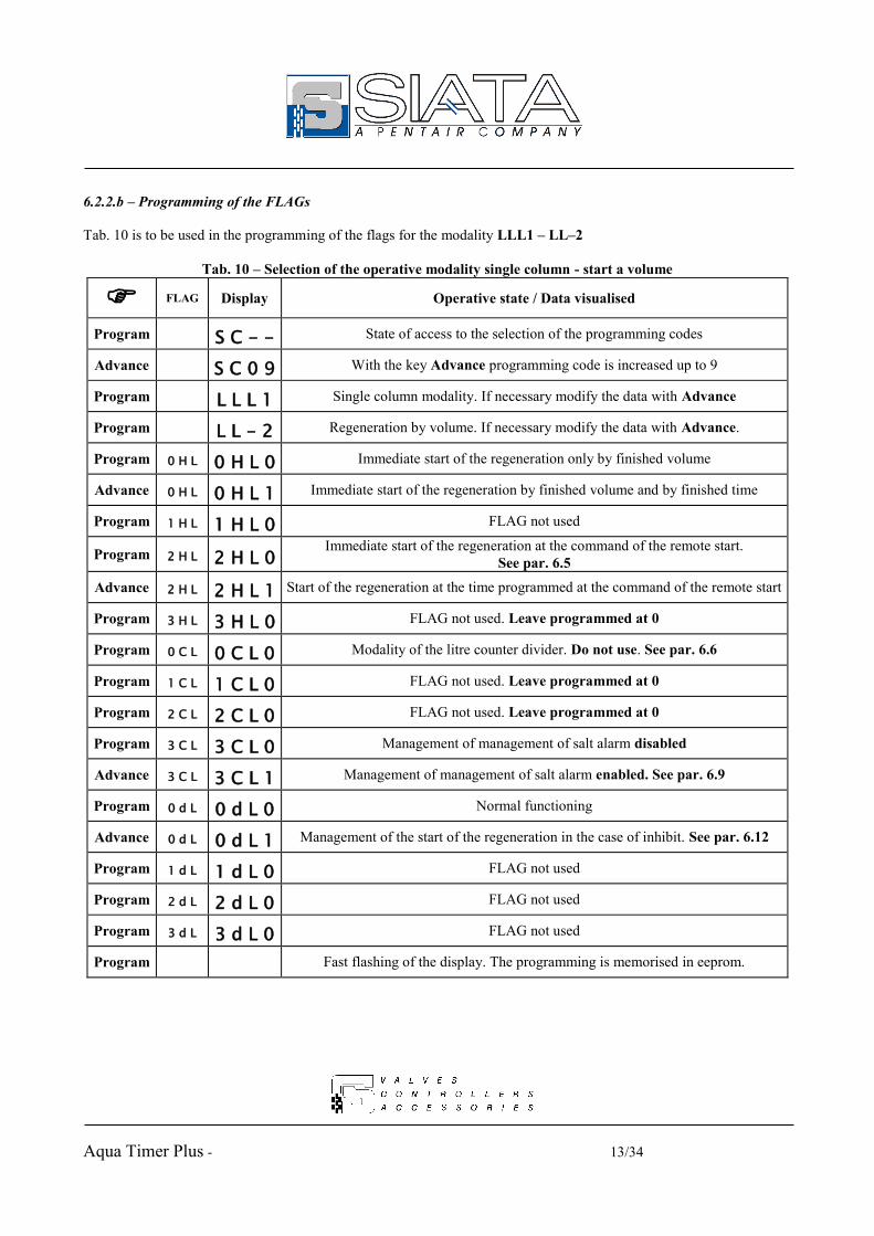
6.2.2.b – Programming of the FLAGs Tab. 10 is to be used in the programming of the flags for the modality LLL1 – LL–2
Tab. 10 – Selection of the operative modality single column - start a volume
FLAG Display Operative state / Data visualised
Program S C - - State of access to the selection of the programming codes
Advance S C 0 9 With the key Advance programming code is increased up to 9
Program L L L 1 Single column modality. If necessary modify the data with Advance
Program L L - 2 Regeneration by volume. If necessary modify the data with Advance.
Program 0 H L 0 H L 0 Immediate start of the regeneration only by finished volume
Advance 0 H L 0 H L 1 Immediate start of the regeneration by finished volume and by finished time
Program 1 H L 1 H L 0 FLAG not used
Program 2 H L 2 H L 0 Immediate start of the regeneration at the command of the remote start.
See par. 6.5
Advance 2 H L 2 H L 1 Start of the regeneration at the time programmed at the command of the remote start
Program 3 H L 3 H L 0 FLAG not used. Leave programmed at 0
Program 0 C L 0 C L 0 Modality of the litre counter divider. Do not use. See par. 6.6
Program 1 C L 1 C L 0 FLAG not used. Leave programmed at 0
Program 2 C L 2 C L 0 FLAG not used. Leave programmed at 0
Program 3 C L 3 C L 0 Management of management of salt alarm disabled
Advance 3 C L 3 C L 1 Management of management of salt alarm enabled. See par. 6.9
Program 0 d L 0 d L 0 Normal functioning
Advance 0 d L 0 d L 1 Management of the start of the regeneration in the case of inhibit. See par. 6.12
Program 1 d L 1 d L 0 FLAG not used
Program 2 d L 2 d L 0 FLAG not used
Program 3 d L 3 d L 0 FLAG not used
Program Fast flashing of the display. The programming is memorised in eeprom.

Aqua Timer Plus - 14/34
6.2.2.c – List of codes to be programmed For the programming and the meaning of the codes see par. 6.3. In this modality the programming of the following codes is recommended:
Tab. 11 – Table of the codes in one single column modality LLL1 – LL–2 Code Meaning SC03 Programming of the regeneration cycle ( stop times ) SC04 Programming of the litre counter divider ( pre-scaler )
SC05 Programming of the duration of the end of cycle impulse and of the litre counter divider of the dosing pump
SC06 Programming of the volume of resin, of the percentage of reserve and of the capacity of exchange SC01 Programming of the hardness value SC00 Initialisation of the system
If the flag 0HL has been programmed with the value 1 to also have the regeneration by time, the programming recommended varies as follows:
Tab. 12 – Table of the codes in one single column modality LLL1 – LL–2 Code Meaning SC02 Programming of the time of regeneration and the interval days between two regenerations SC03 Programming of the regeneration cycle ( stop times ) SC04 Programming of the litre counter divider ( prescaler ) SC05 Programming of the duration of the end of cycle impulse and of the litre counter divider of the
dosing pump SC06 Programming of the volume of resin, of the percentage of reserve and of the capacity of exchange SC01 Programming of the hardness value SC00 Initialisation of the system
6.2.3 - LLL1 – LL–3 – One single column with mixed time / volume start. 6.2.3.a –Operative characteristics. In this operative modality, the regeneration starts exclusively when the interval days have passed and at the programmed time. If the volume of water treated reaches the value calculated for the reserve, the residual days will be ignored. It is not possible to have the immediate start of the regeneration either because the volume has run out, or because the value of the reserve has been reached. The control on the reserve is automatic and cannot be dis-activated. The control on the remote start is available, and can start up the regeneration both immediately and deferred to the programmed time, based on the content of the flag 2HL. In this operative modality the possibility of using the cam with the stand-by is not available.

Aqua Timer Plus - 15/34
6.2.3.b – Programming of the FLAGs Tab. 13 is to be used in the programming of the flags for the modality LLL1 – LL–3
Tab. 13 – Selection of the operative modality single column - start in mixed mode
FLAG Display Operative state / Data visualised
Program S C - - State of access to the selection of the programming codes
Advance S C 0 9 With the key Advance the programming code is increased up to 9
Program L L L 1 Single column modality. If necessary modify the data with Advance
Program L L - 3 Mixed regeneration. If necessary modify the data with Advance.
Program 0 H L 0 H L 0 FLAG not used
Program 1 H L 1 H L 0 Interval between two regenerations expressed in days. See par. 6.3.2
Advance 1 H L 1 H L 1 Regeneration to be carried out on the days of the week programmed.
Program 2 H L 2 H L 0 Immediate start of the regeneration at the command of the remote start.
See par. 6.5
Advance 2 H L 2 H L 1 Start of the regeneration at the programmed time at the command of the remote
start
Program 3 H L 3 H L 0 FLAG not used. Leave programmed at 0
Program 0 C L 0 C L 0 Modality of the litre counter divider. Do not use. See par. 6.6
Program 1 C L 1 C L 0 FLAG not used. Leave programmed at 0
Program 2 C L 2 C L 0 FLAG not used. Leave programmed at 0
Program 3 C L 3 C L 0 Management of salt alarm disabled
Advance 3 C L 3 C L 1 Management of salt alarm enabled. See par. 6.9
Program 0 d L 0 d L 0 Normal functioning
Advance 0 d L 0 d L 1 Management of the start of the regeneration in the case of inhibit. See par. 6.12
Program 1 d L 1 d L 0 FLAG not used
Program 2 d L 2 d L 0 FLAG not used
Program 3 d L 3 d L 0 FLAG not used
Program Fast flashing of the display. The programming is memorised in eeprom.

Aqua Timer Plus - 16/34
6.2.3.c – List of codes to be programmed For the programming and the meaning of the codes see par. 6.3. In this modality, the programming of the following codes is recommended:
Tab. 14 – Table of the codes in one single column modality LLL1 – LL–3 Code Meaning SC02 Programming of the time of regeneration and of the interval days between two regenerations SC03 Programming of the regeneration cycle ( stop times ) SC04 Programming of the litre counter divider ( prescaler )
SC05 Programming of the duration of the end of cycle impulse and of the litre counter divider of the dosing pump
SC06 Programming of the volume of resin, of the percentage of reserve and of the exchange capacity SC01 Programming of the hardness value SC00 Initialisation of the system
6.2.4 – LLL2 – LL–1 – A duplex column with start by time. 6.2.4.a – Operative characteristics In this operative modality, the regeneration starts exclusively at the programmed time after the interval days programmed ( or on the days of the week selected ). No control is available on the volume or on the reserve. Control is available on the remote start, which can start up the regeneration both immediately and deferred to the programmed time, on the basis of the content of the flag 2HL. It is possible to use the cam with the stand-by. (see par. 6.8) 6.2.4.b – Programming of the FLAGs Tab. 15 is to be used in the programming of the FLAG for the modality LLL2 – LL–1
Tab. 15 – Selection of the operative modality duplex column – start by tempo
FLAG Display Operative state / Data visualised
Program S C - - State of access to the selection of the programming codes
Advance S C 0 9 With the key Advance the programming code is increased up to 9
Program L L L 2 Modality duplex column. If necessary modify the data with Advance
Program L L - 1 Regeneration a tempo. If necessary modify the data with Advance.
Program 0 H L 0 H L 0 FLAG not used
Program 1 H L 1 H L 0 Interval between two regenerations expressed in days. See par. 6.3.2
Advance 1 H L 1 H L 1 Regeneration to be carried out on the days of the week programmed.
Program 2 H L 2 H L 0 Immediate start of the regeneration at the command of the remote start.
See par. 6.5
Advance 2 H L 2 H L 1 Start of the regeneration at the programmed time on the command of the remote
start
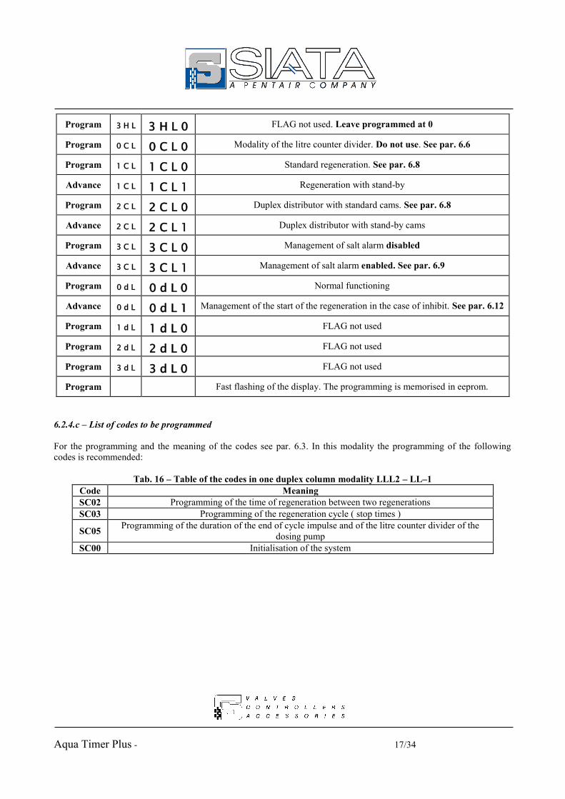
Aqua Timer Plus - 17/34
Program 3 H L 3 H L 0 FLAG not used. Leave programmed at 0
Program 0 C L 0 C L 0 Modality of the litre counter divider. Do not use. See par. 6.6
Program 1 C L 1 C L 0 Standard regeneration. See par. 6.8
Advance 1 C L 1 C L 1 Regeneration with stand-by
Program 2 C L 2 C L 0 Duplex distributor with standard cams. See par. 6.8
Advance 2 C L 2 C L 1 Duplex distributor with stand-by cams
Program 3 C L 3 C L 0 Management of salt alarm disabled
Advance 3 C L 3 C L 1 Management of salt alarm enabled. See par. 6.9
Program 0 d L 0 d L 0 Normal functioning
Advance 0 d L 0 d L 1 Management of the start of the regeneration in the case of inhibit. See par. 6.12
Program 1 d L 1 d L 0 FLAG not used
Program 2 d L 2 d L 0 FLAG not used
Program 3 d L 3 d L 0 FLAG not used
Program Fast flashing of the display. The programming is memorised in eeprom.
6.2.4.c – List of codes to be programmed For the programming and the meaning of the codes see par. 6.3. In this modality the programming of the following codes is recommended:
Tab. 16 – Table of the codes in one duplex column modality LLL2 – LL–1 Code Meaning SC02 Programming of the time of regeneration between two regenerations SC03 Programming of the regeneration cycle ( stop times )
SC05 Programming of the duration of the end of cycle impulse and of the litre counter divider of the dosing pump
SC00 Initialisation of the system

Aqua Timer Plus - 18/34
6.2.5 – LLL2 – LL–2 – One duplex column with start by volume. 6.2.5.a – Operative characteristics. In this operative modality the regeneration starts exclusively when the volume reaches the value 0. The flag 0HL allows for the enabling also of the start of the regeneration by time. Thus, the immediate start of the cycle by finished volume remains unchanged to which the start of the cycle at the programmed time after the interval days programmed or on the active days is added. The control on the reserve is not available. The control on the remote start is available, and can start up the regeneration both immediately and deferred to the programmed time, on the basis of the content of the flag 2HL. In this operative modality it is not possible to activate the cycle with the stand-by. 6.2.5.b – Programming of the FLAGs Tab. 17 is to be used in the programming of the flags for the modality LLL2 – LL-2
Tab. 17 – Selection of the operative modality duplex column – start by volume
FLAG Display Operative state / Data visualised
Program S C - - State access to the selection of the programming codes
Advance S C 0 9 With the key Advance the programming code is increased up to 9
Program L L L 2 Modality duplex column. If necessary modify the data with Advance
Program L L - 2 Regeneration a volume. If necessary modify the data with Advance.
Program 0 H L 0 H L 0 Immediate start of the regeneration only by finished volume
Advance 0 H L 0 H L 1 Immediate start of the regeneration by finished volume and by finished time
Program 1 H L 1 H L 0 FLAG not used
Program 2 H L 2 H L 0 Immediate start of the regeneration at the command of the remote start.
See par. 6.5
Advance 2 H L 2 H L 1 Start of the regeneration at the programmed time at the command of the remote start
Program 3 H L 3 H L 0 FLAG not used. Leave programmed at 0
Program 0 C L 0 C L 0 Modality of the litre counter divider. Do not use. See par. 6.6
Program 1 C L 1 C L 0 Regeneration standard. See par. 6.8
Advance 1 C L 1 C L 1 Regeneration with stand-by
Program 2 C L 2 C L 0 Duplex distributor with standard cams. See par. 6.8
Advance 2 C L 2 C L 1 Duplex distributor with stand-by cams

Aqua Timer Plus - 19/34
Program 3 C L 3 C L 0 Management of salt alarm disabled
Advance 3 C L 3 C L 1 Management of salt alarm enabled. See par. 6.9
Program 0 d L 0 d L 0 Normal functioning
Advance 0 d L 0 d L 1 Management of the start of the regeneration in the case of inhibit. See par. 6.12
Program 1 d L 1 d L 0 FLAG not used
Program 2 d L 2 d L 0 FLAG not used
Program 3 d L 3 d L 0 FLAG not used
Program Fast flashing of the display. The programming is memorised in eeprom.
6.2.5.c – List of codes to be programmed For the programming and the meaning of the codes see par. 6.3. In this modality the programming of the following codes is recommended:
Tab. 18 – Table of the codes in one duplex column modality LLL2 – LL–2 Code Meaning SC03 Programming of the regeneration cycle ( stop times ) SC04 Programming of the litre counter divider ( prescaler )
SC05 Programming of the duration of the end of cycle impulse and of the litre counter divider of the dosing pump
SC06 Programming of the volume of resin, of the percentage of reserve and of the exchange capacity SC01 Programming of the hardness value SC00 Initialisation of the system
If the flag 0HL has been programmed with the value 1 to have also the regeneration by time, the recommended programming varies as follows:
Tab. 19 – Table of the codes in the one duplex column LLL2 – LL–2 Code Meaning SC02 Programming of the time of regeneration and of the interval days between two regenerations SC03 Programming of the regeneration cycle ( stop times ) SC04 Programming of the litre counter divider ( prescaler )
SC05 Programming of the duration of the end of cycle impulse and of the litre counter divider of the dosing pump
SC06 Programming of the volume of resin, of the percentage of reserve and of the exchange capacity SC01 Programming of the hardness value SC00 Initialisation of the system

Aqua Timer Plus - 20/34
6.2.6 – LLL2 – LL–3 – One duplex column with mixed time / volume start. 6.2.6.a – Operative characteristics. In this operative modality the control for the start of the regeneration depends on the use or otherwise of the cam with stand-by, that is of the programming of the flags 1CL and 2CL. If both of the flags are programmed with the value 0, the regeneration cycle is standard in 4 phases of 25 seconds. The start of the cycle is controlled by the running out of the interval time between two regenerations, or by the running out of the volume. The latter condition, differently from that described in par. 6.2.3.a, does not activate a request for regeneration to be carried out at the programmed time, but causes the immediate start of the cycle. The same effect is obtained also by programming to 1 only the flag 2CL, that is when the standard regeneration cycle standard with a stand-by cam is required to be carried out. If both of the flags are programmed with the value 1, the controller carries out the regeneration with stand-by. In this case, the running out of the volume causes a request for regeneration which will be carried out at the programmed time. The controller will immediately position the cam in the stand-by position, that is it will carry out the exchange of the columns. The regeneration will start from the stand-by position. The control on the reserve is not available. The control on the remote start is available, and this can start up the regeneration both immediately and deferred to the programmed time, on the basis of the content of the flag 2HL. 6.2.6.b – Programming of the FLAGs Tab. 20 is to be used for the programming of the flags for the modality LLL2 – LL-3
Tab. 20 – Selection of the operative modality duplex column - start in mixed mode
FLAG Display Operative state / Data visualised
Program S C - - State of access to the selection of the programming codes
Advance S C 0 9 With the key Advance the programming code is increased up to 9
Program L L L 2 Duplex column modality. If necessary modify the data with Advance
Program L L - 3 Mixed regeneration. If necessary modify the data with Advance.
Program 0 H L 0 H L 0 FLAG not used
Program 1 H L 1 H L 0 Interval between two regenerations expressed in days. See par. 6.3.2
Advance 1 H L 1 H L 1 Regeneration to be carried out on the days of the week programmed.
Program 2 H L 2 H L 0 Immediate start of the regeneration at the command of the remote start.
See par. 6.5
Advance 2 H L 2 H L 1 Start of the regeneration at the programmed time on the command of the remote
start

Aqua Timer Plus - 21/34
Program 3 H L 3 H L 0 FLAG not used. Leave programmed at 0
Program 0 C L 0 C L 0 Modality of the litre counter divider. Do not use. See par. 6.6
Program 1 C L 1 C L 0 Standard regeneration. See par. 6.8
Advance 1 C L 1 C L 1 Regeneration with stand-by
Program 2 C L 2 C L 0 Duplex distributor with standard cams. See par. 6.8
Advance 2 C L 2 C L 1 Duplex distributor with stand-by cams
Program 3 C L 3 C L 0 Management of salt alarm disabled
Advance 3 C L 3 C L 1 Management of salt alarm enabled. See par. 6.9
Program 0 d L 0 d L 0 Normal functioning
Advance 0 d L 0 d L 1 Management of the start of regeneration in the case of inhibit. See par. 6.12
Program 1 d L 1 d L 0 FLAG not used
Program 2 d L 2 d L 0 FLAG not used
Program 3 d L 3 d L 0 FLAG not used
Program Fast flashing of the display. The programming is memorised in eeprom.
6.2.6.c – List of codes to be programmed For the programming and the meaning of the codes see par. 6.3. In this modality the programming of the following codes is recommended:
Tab. 21 – Table of the codes in one duplex column modality LLL2 – LL–3 Code Meaning SC02 Programming of the time of regeneration and interval days between two regenerations SC03 Programming of the regeneration cycle (stop times ) SC04 Programming of the litre counter divider ( prescaler )
SC05 Programming of the duration of the end of cycle impulse and of the litre counter divider of the dosing pump
SC06 Programming of the volume of resin, of the percentage of reserve and of the exchange capacity SC01 Programming of the hardness value SC00 Initialisation of the system

Aqua Timer Plus - 22/34
6.3 – Programming codes 6.3.1 – Access to the programming codes To access the programming codes the sequence tab. 22 must be followed, remembering that described in par. 6.2 regarding the presence of a protection code.
Tab. 22 – Access to the programming codes
Display Meaning
PROGRAM S C - - Code of access to the programming
ADVANCE S C 0 0 Composition of the number on the display, pressing Advance the number of times needed to select the code required.
PROGRAM Varies depending on
code Confirms the code selected and accesses its programming
6.3.2 – List of programming codes and their meaning The key Advance allows the flashing characters to be increased, the key Code returns the flashing digits to zero, the key Program confirms the value programmed.
Tab. 23 – Table of the programming codes Code
visualised Display Meaning
S C 0 0 PROGRAM Initialisation of the system. Carries out the calculations on the treatable volume and visualises the new value. Causes any regeneration in progress to end immediately.
S C 0 1 PROGRAM d H x x Programming of the hardness value of the water from 1 to 99. The hardness value must be expressed in French degrees.
S C 0 2
PROGRAM 0 2 . 3 0 Start time of the regeneration. With the key Program go from the minutes to the hours
PROGRAM
L – 3 0 Programming of the interval days between two regenerations. The value programmable can vary from 01 to 30.
1 L L 0
If the flag 1HL is programmed with the value 1, instead of setting the interval in days between two regenerations, set the days of the week on which the regeneration must be carried out. (1LL1 = Monday, 2LL1 = Tuesday, etc.). The value 1 in the day, indicates that the day is active. With the key Program the next day is moved on to.
PROGRAM d d 3 0
If the flag 3CL is programmed with the value 1, after the interval days have been reset, the number of regeneration’s which can be carried out with the salt load introduced into the system may be set (see par. 6.9) from 1 to 99.
PROGRAM d A 0 5 Setting of the reserve of regenerations which can be carried out with the salt introduced. (see par. 6.9).

Aqua Timer Plus - 23/34
Code
visualised Display Meaning
S C 0 3 PROGRAM 1 C 1 0 Programming of the regeneration cycle times. With the key Program the next phase is accessed
S C 0 4
PROGRAM - - - 0
Programming of the litre counter divider. This value indicates the type of litre counter divider: 0 =free litre counter divider, 1 = litre counter divider pre-programmed. This programming acts directly on the flag 0CL.
PROGRAM x x x x If the free litre counter divider has been chosen, a value of between 0 and 899 impulses / litre may be set.
1 4.0 1 If the pre-programmed litre counter divider has been chosen, one of the values suggested in tab. 24, par. 6.6 may be programmed.
S C 0 5 PROGRAM x x x x
Programming of the duration in minutes and seconds of the end of cycle impulse, from 0 to 59 minutes and 59 seconds.
PROGRAM x x x x Divider of the dosing pump, programmable from 0 to 9999 impulses / litre.
S C 0 6
PROGRAM x x x x Programming of the volume of resin in the cylinder: the value can vary from 0 to 9999 litres.
PROGRAM H H 5 0 Programming of the percentage of the total volume total of treatable water which must be held in reserve.
PROGRAM C H 5.0 Programming of the value of capacity of exchange of the resin; the value can vary from 1.4 to 9.0.
S C 0 7 PROGRAM x x x x Programming of the code of access to the programming functions. Using the key Advance, any value from 0 to 9999 may be set.
S C 0 8 PROGRAM x.x.x x
Allows the total counter of the volume consumed to be visualised. This cannot be modified, but only visualised. Since it is composed of 8 digits, it is visualised in two parts; These are the 4 higher numbers.
PROGRAM x x x.x. These are the 4 lower numbers.
S C 0 9 PROGRAM S C - - Allows access to the general programming and to the setting of the flags as already described in the previous paragraphs.
6.4 – Programming of the reserve Aqua Timer Plus allows for the volume of water treatable to be controlled, comparing it to a possible value of reserve, but only working in the single column modality with mixed control for the start of the regeneration. The percentage of reserve is programmed using the code SC02 and expresses the percentage of the total volume available which must be held in reserve. In this way, if there are 25,000 treatable litres available and 30% of reserve is required, the value HH30 must be programmed in the code SC02 and the code SC00 must be keyed in to have the calculations on the volume carried out. When the volume reaches the value 7,500, a regeneration which will be carried out at the programmed time will be set. N.B.!! The control of the reserve is active only in the “one single column” modality with mixed control for the regeneration.

Aqua Timer Plus - 24/34
6.5 – Remote Start Aqua Timer Plus offers a “remote start” entry which allows for the regeneration to be started up by an external automatism or by a button placed at a distance from the system. Whichever device is used, it normally open type, and to start up the regeneration it must be closed for at least 15 seconds. The regeneration by remote start can start both immediately and deferred to the programmed time, depending on what is programmed in the flag 2HL. 6.6 – Programming of the litre counter divider ( prescaler ) The programming of the litre counter divider defines the ratio between the number of impulses read by Aqua Timer Plus and the unit of load in transit in the counter used ( litres or m³) . Aqua Timer Plus has two work modes: free prescaler if the flag 0CP is equal to 0; in this case the prescaler may be programmed within the range of
values 1 899 (n° of impulses given by the litre counter before the volume climbs by one unit); pre-programmed prescaler; in this case the litre counter dividers which can be used are those indicated in the
first column of table 24;
Tab.24 – Table of the pre-programmed litre counter dividers Type of litre counter divider (impulses / litre) Representation on the display
14 / 01 1 4.0 1
4 / 1 0 4.0 1
1 / 1 0 1.0 1
4 / 10 0 4.1 0
2 / 10 0 2.1 0
1 / 10 0 1.1 0
4 / 100 4.1 0 0
2 / 100 2.1 0 0
1 / 100 1.1 0 0
4 / 1000 4.0 0 0
2 / 1000 2.0 0 0
1 / 1000 1.0 0 0

Aqua Timer Plus - 25/34
The volume calculated by Aqua Timer Plus can go from 0 to 999,999 litres. This value is optimised in order to be able to be visualised by the display of the controller which can show only four digits. A decimal point will appear on the display to separate the Timer metres from the litres, that is the thousands of litres from the hundreds. The value of the volume will be visualised from the left to the right, so that a volume value of 15,500 litres will be visualised as 15.50, a value of 350,000 litres will appear as 350.0. During the service, the normal consumption of water will cause the volume visualised to decrease; when the most significant digit becomes zero, Aqua Timer Plus will optimise the visualisation moving the reference point towards the left, which allows new, less significant digits to be seen. Thus, the moment the volume passes from 10,000 to 9,999 litres, the visualisation will pass from 10.00 to 9.999, if the volume passes from 100,000 to 99,900 litres, the visualisation passes from 100.0 to 99.90. If using a pre-programmed prescaler, the volume calculated is optimised by returning to zero the digits which are not decreased and by rounding it off. Example: If the volume calculated is 15,435 litres and the prescaler is programmed with the type 1/10, the volume will be decreased by 10 litres each impulse, so that the final 5 would never be returned to zero. The volume will therefore be optimised, returning to zero the last digit so obtaining the value 15,430; similarly, if the litre counter divider chosen is the type 4/1000, the volume will be decreased by 1000 litres every 4 impulses, and the 435 litres will never be returned to zero. The volume will be optimised to 15,000 litres and will be visualised as such on the display. 6.7 – Calculation of the cyclic capacity of a system Aqua Timer Plus is able to calculate autonomously the volume of water that the system is capable of treating. The calculation is carried out using the parameters shown below. The calculation is carried out automatically after the programming of the hardness, otherwise it can be carried out by using the code 2C00.
1000 x A x B Treatable litres = C Where : A = Volume of resin in litres B = Capacity of ionic exchange of the resin, on average 5 (gr of CaCO3 / litre of resin) C = Hardness of the water in French degrees [° F]

Aqua Timer Plus - 26/34
6.8 – Functionality of the regeneration cycle, flags 1CL and 2CL. When Aqua Timer Plus is programmed to control one duplex column, it is possible to use a special distributor, equipped with a stand-by position at the beginning of the regeneration. The controller provides two flags, 1CL and 2CL, which must be programmed together to select the operative modality of the regeneration cycle. The flag 1CL selects the type of regeneration; standard, composed of 4 phases , or with stand-by, composed of 3 phases. The flag 2CL selects the type of cam; standard or with stand-by. Depending on how they are combined, the controller modifies the carrying out of the regeneration cycle, and in the particular case of the duplex with mixed control modality (par. 6.2.6), the type of control on the start of the cycle also changes. The two flags can be composed thus:
Type 1CLx 2CLx Description 1 0 0 Standard regeneration – standard cam. 2 0 1 Standard regeneration – cam with stand-by. 1 0 Selection not valid. Works as Type 1.
3 1 1 Regeneration with stand-by – cam with stand-by. The controller modifies the regeneration cycle as follows: Type 1 The cycle is composed of 4 phases with movement times of 25 seconds each (Tab.25). Type 2 The cycle is modified by the presence of the cam with stand-by. The position of stand-by is positioned at 25
seconds of rotation from the stroke end position and must be passed. The rotation time of the first phase must therefore be of 50 seconds, 25 dedicated to reaching the position of stand-by and 25 to reach the position expected for the first phase. The movement time between the second and third phases of the cycle is returned to zero, losing the slow rinse after the aspiration. The rest of the cycle remains unchanged. (Tab. 26).
Type 3 As soon as the condition necessary for the start of the regeneration is in place, the controller puts the cam in movement for 25 seconds, until the position of stand-by has been reached. This is the start point of the real regeneration cycle, which can start immediately or at the programmed time depending on the operative modality. The first phase of movement is of 25 seconds. The phase of movement between the second phase and the third is annulled, thus losing the phase of slow rinse after the aspiration. (Tab. 27).
With reference to the description of the Type 3, the start of the regeneration will be : Immediate If the controller is set in time or mixed mode and the time programmed for the start of the cycle has
arrived with the days run out or if it is a day programmed for the regeneration; Immediate If the controller is set in volume mode with the flag 0HL programmed to 0, that is the immediate start by
finished volume, and the volume has run out; Deferred If the controller is set in volume mode with the 0HL programmed to 1, that is the deferred start to the
programmed time by finished volume, and the volume has run out; Deferred If the controller is set in mixed mode and the regeneration has been activated by the finished volume.

Aqua Timer Plus - 27/34
Tab. 25 – Time diagram of the standard regeneration cycle (Type 1).
1C 2C 3C 4C Search of the stroke
end Stop Stop Stop Stop Stroke end Stroke end = Movement phase of 25 seconds.
Tab. 26 – Time diagram of the standard regeneration cycle and cam with stand-by (Type 2). Pos. of stand-by 1C 2C 3C 4C Search of the stroke
end Stop Stop Stop Stop Stroke end Stroke end = Movement phase of 25 seconds.
Tab. 27 – Time diagram of the regeneration cycle with stand-by (Type 3). Stand-by 1C 2C 3C 4C Search of the stroke
end Waiting time Stop Stop Stop Stop Stroke end Stroke end = Movement phase of 25 seconds.

Aqua Timer Plus - 28/34
6.9 – Management of the alarm of end of regenerative autonomy The installer sizing and putting together the system knows the dimensions of the canisters, how much resin will be contained in them and how much salt will be consumed for each regeneration. Knowing how much salt to put into the system he can therefore know more or less how many regenerations are possible with the salt introduced. Aqua Timer Plus allows the possibility to programme this value and to decrease it at each regeneration in order to be able to provide a general indication of how many regenerations are still possible before the salt runs out. This functionality will be activated via the flag 3CL which must be programmed with the value 1. Once this programming has been carried out, calling up the programming code SC02, after having programmed the time of regeneration and the interval days, it is possible to programme the number of regenerations which can be carried out (see par. 6.3.2) and a number of reserve regenerations. The functioning is as follows: Once the programming has been carried out, the key Reset must be pressed to activate the values set. With the key Advance the mode of visualisation of the display can be changed so as to see first d-xx which is the value of reserve set, then ddxx which is the residual number of regenerations which can be carried out. As soon as the residual number of regenerations which can be carried out (ddxx) is equal to the programmed number of reserve regenerations (d-xx), the led SALT comes on on the panel of Aqua Timer Plus to indicate that the above situation has been reached. Starting from this moment, and in any case before the number of reserve regenerations has run out, the operator must be sure to introduce salt into the system ( of a quantity which will take the level back to its original ) and press the key Reset to reset the counters and turn off the led SALT. When the number of regenerations which can be carried out reaches the value dd00, one last regeneration is available, after which Aqua Timer Plus is blocked with the leds SALT and ALARM which come on and the letters –SAL lit solidly on the display. At this point the operator must intervene, introducing more salt and pressing the key Reset. Obviously, if the key Reset is pressed without having introduced more salt to the system, Aqua Timer Plus will carry out the regenerations of the system, without salt. 6.10 – Putting into service IMPORTANT Remember always to key in the code SC00 (ref. par. 6.3) after the various phases of programming before Aqua Timer Plus is put into service. Always remember that before it is possible to carry out operations on the keypad of Aqua Timer Plus, it must be checked that the cam of the distributor is in the stroke end position (except when it is in regeneration, a condition which can be checked by using the key Advance putting the display into the visualisation mode of the regeneration - see par. 4). If it is intended to programme Aqua Timer Plus before its installation, that is without the distributor connected, the limit switch entry must be closed with a connector bridge. During the normal functioning of Aqua Timer Plus, the leds A or B will be on to indicate which column is in service. During the service, the impulses coming from the litre counter sensor, as well as decreasing the volume available through the litre counter divider set with the programming code SC04, also acts on the counter of the dosing pump programmed with the programming code SC05 (See par. 6.3.2). The value set represents the number of impulses which must be read by the controller to have an impulse at the dosing pump. The duration of this impulse cannot be modified. With the programming code SC05 the duration of the end of cycle impulse is also modified. This time starts as soon as the stop time of the last phase of the regeneration cycle ends, and the motor starts to move to take the cam of the distributor into the stroke end position.

Aqua Timer Plus - 29/34
6.11 – Connections The drawing shown on the attached page A shows the general connections of the controller, also available on a sticker positioned under the cover giving access to the terminal board. The drawings shown on the attached pages B and C, show the connections between the controller and, respectively, one single distributor and one duplex distributor. With reference to attached page C, the cables cod. 96-M and 96-S may be assembled in any way. The cable cod. 96-AB1, on the other hand, is polarised and it is important that it should be assembled as shown in the attached page C. With reference to the attached page B, the cable cod. 96-M is not polarised and may be assembled in any way. The cable cod. 96-S on the contrary, is polarised. If, after the assembly, positioning the distributor at the stroke end, the LED Service on the distributor does not come on, the connection of the cable cod. 96-S must be inverted. With reference to the attached page A, two types of litre counter may be used, the SIATA magnetic sensor with Hall effect, and the Reed counter, or otherwise a counter which however supplies a simple closure between two wires. In the first case, using the cables SIATA turbine sensor, the following connections must be made:
Tab.19 – Connections of the magnetic sensor with Hall effect COLOUR FUNCTION TERMINALS
White + 12 26 Green Ground 27 Brown Signal 28
In the case of a duplex system, the magnetic sensor is the same for both of the columns. The connections shown in the table must be respected rigorously, to avoid damaging the sensor. In the second case, there are only two wires between which there is a closure for each impulse. These wires must be connected to the terminals 27 and 28. The connections of this type of counter are not polarised. They may be assembled in any way. 6.12 – Management of the inhibit signal. Flag 0dL. In the previous paragraphs, it has been shown that each operative modality has its own type of control on the work parameters to activate the regeneration cycle. The start of the cycle may be blocked via an inhibit signal to be applied on terminals 7 and 21 of the controller. When these are closed between them, the start of the cycle is blocked until the signal stops being applied. This situation effects the functioning cycle of the controller in a different way depending on the operative modality being used at the time. Suppose that the controller is programmed in the Volume mode. In the paragraphs 6.2.2 and 6.2.5 it has been shown that as soon as the volume has run out, the cycle starts immediately. If when the volume runs out there is the inhibit signal, the cycle will not start; as soon as the signal disappears, the cycle will start. Suppose now to be in any operative modality which allows for the start of the cycle when the interval Time between two regenerations runs out. The regeneration will start when the local time is equal to the programmed time for the start of the cycle and the interval days have passed, or on an active day, or otherwise there will be the deferred start by finished volume in which case the interval days are not checked.
Aqua Timer Plus - 30/34
Suppose therefore to have programmed the time 02.30 as the start time of the regeneration. When the internal clock reaches the time 02.30 the cycle will start, taking for granted that the days have finished. If when the clock reaches the time programmed for the start of the cycle the inhibit signal is active, the start is obviously blocked. If the inhibit signal disappears during the minute in which the local time is the same as the time programmed for the start of the cycle, the regeneration will start. If, however, the inhibit signal disappears when the clock has passed the time programmed for the start of the cycle, the regeneration will not be able to start until the conditions are repeated, that is after 24 hours. To avoid waiting for 24 hours with the system not regenerated, it is possible to programme with the value 1 the flag 0dL. With this programming the regeneration will start as soon as the inhibit signal stops being applied, whatever the time is. Referring to the above example, suppose that the inhibit signal activates at 02.00. When the clock arrives at 02.30 the regeneration is obviously blocked. At 05.35 the inhibit signal disappears and the regeneration starts. It is important to consider that, using this flag, there is the possibility of having the regeneration of the resins at a time considered undesirable.

Aqua Timer Plus - 31/34
7 – What to do if …
Some basic operations for the resolution of small problems which may arise during the use of Aqua Timer Plus are described below. If the suggestions shown do not help to resolve the situation, please call the SIATA service assistance.
7.1 - ... Aqua Timer Plus does not come on ?
1. Check that the plug is correctly inserted in the electricity socket;2. Check that the socket is correctly supplied;3. Check that the current conductors are corrected inserted into the terminals and that these are closed correctly.4. Check that the fuse positioned on the panel has not blown.
In the case of Aqua Timer Plus at 230 Vac, AT-PLUS2/05, this fuse must be of delayed 0.5A;
7.2 - ... the motors of the distributors do not stop ?
1. Check that the run end wires of the distributors, marked 96-S, are correctly inserted in the terminals and that theseare closed correctly;
7.3 - ... there is no current to the utilisers?
1. Remember that Aqua Timer Plus does not supply current to the outlets, but only closures that the operator mustwire at his own discretion, check that the wiring is correct, that the conductors are correctly inserted into the
terminals and that these are closed correctly;
7.4 - ... Aqua Timer Plus works in an irregular way?
1. Check that the distributors are at the stroke end, that is that the motors are not in movement;2. Check that the controller is correctly programmed;3. Key in the code 220 to initialise Aqua Timer Plus;

Aqua Timer Plus - 32/34
Appendix A (General electrical connections)
CE0027

Aqua Timer Plus - 33/34
Appendix B (Electrical connections for the single distributor) CE0028

Aqua Timer Plus - 34/34
Appendix C (Electrical connections for the duplex distributor) CE0021
Distributed by:
37 Tannery Lane#06-08 Tannery HouseSingapore 347790Tel: +65 6741 2994 • Fax: +65 6741 2995
S.I.A.T.A Asia Pacific Pte LtdDistributed by:
www.siata.com.sg