distribution automation abb oy feeder protection · pdf filefeeder protection ref615 designed...
TRANSCRIPT

©20
08 A
BB
Oy
9/26
/200
8-1
-1M
RS
7564
07 C
Feeder ProtectionREF615 Ver. 1.1
Technical Presentation
ABB OyDistribution Automation
Prashant Ganoo – Regional Product Marketing Manager

©20
08 A
BB
Oy
9/26
/200
8. -
2-
Self Introduction
� Bachelors Degree in Electrical Engineering from MS University of Baroda,(1985), Management Programme for Technologists from Indian Institute of Management, Bangalore.(1996)
� Working with ABB since Jan 86 and have worked in Medium Voltage switchgear and Relay divisions in various departments like vendor development, testing and commissioning, application engineering, order handling and marketing.
� Special area of interest - Generator Protection - GSX5e/REG216-316/REM543� Present Role - Working as Regional Product Marketing Manager for Distribution Automation
Products. Was with ABB Oy, since Jan 2004 till July 2008..� Now based at Kuala Lumpur, Malaysia to support SAS Region Market Countries --> NZ, AU, ID,
SG, MY, TH, VN, PH , IN, BD & SL.� New Contact details :
� Direct Line : +60 3 5628 4787� Mobile : +60 12 2833 463� E-MAIL : [email protected]
Prashant GanooB.E.(ELECT), MPT(IIM-B)Area Marketing ManagerDistribution Automation Power Products
ABB OyP.O. Box 699, FI-65101 Vaasa, Finland Phone : +358 (0) 50 33 42918Fax : +358 (0) 10 22 41094E-mail : [email protected]

©20
08 A
BB
Oy
9/26
/200
8. -
3-
IntroductionIntroduction
Feeder Protection REF615
Application examplesApplication examples
Hardware and optionsHardware and options
Functionality highlightsFunctionality highlights
CommunicationCommunication
Mechanical designMechanical design
Front panel HMIFront panel HMI
ToolsTools
ConclusionsConclusions

©20
08 A
BB
Oy
9/26
/200
8. -
4-
Introduction
Introduction

©20
08 A
BB
Oy
9/26
/200
8. -
5-
Feeder Protection REF615
REF615 is a dedicated feeder protection relay designed for the protection, measurement and supervision of utility substations and industrial power systems
©20
08 A
BB
Oy
9/26
/200
8. -
6-
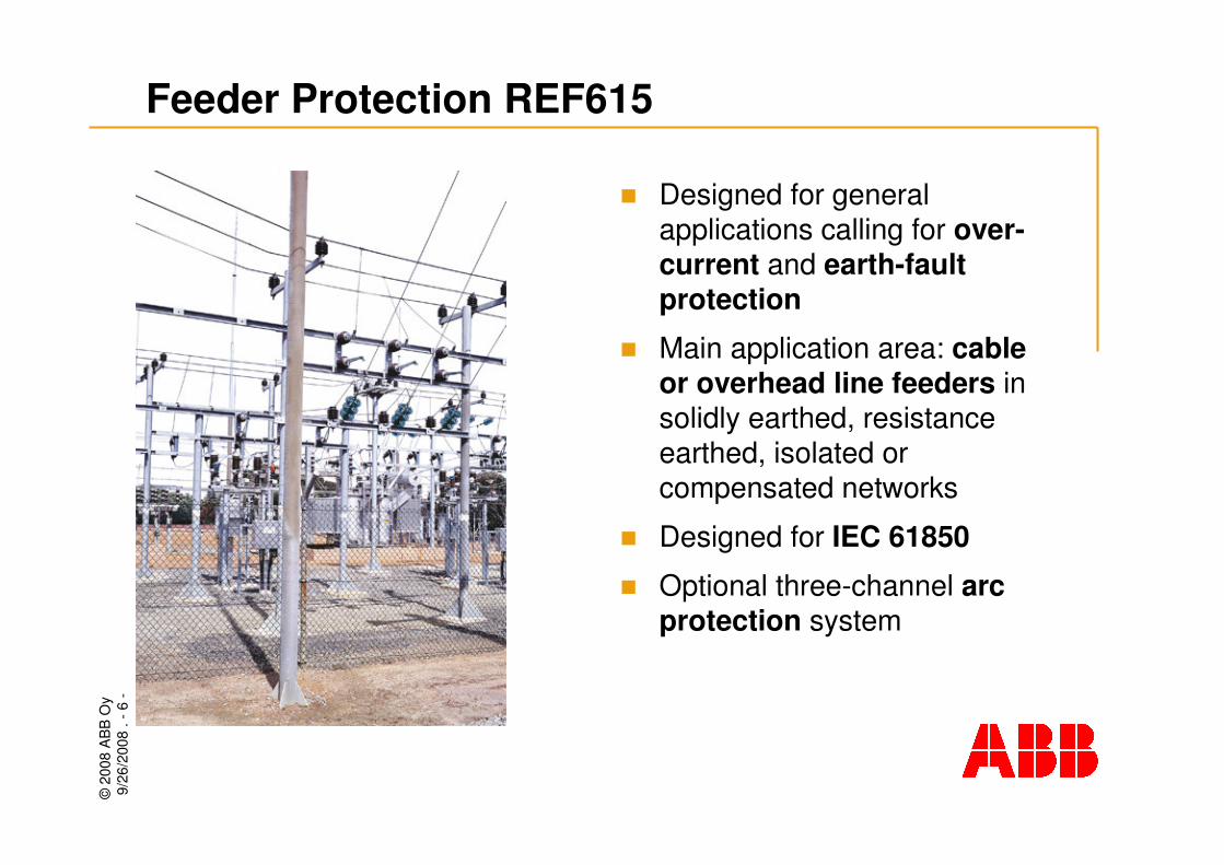
Feeder Protection REF615
� Designed for general applications calling for over-current and earth-fault protection
� Main application area: cable or overhead line feeders in solidly earthed, resistance earthed, isolated or compensated networks
� Designed for IEC 61850
� Optional three-channel arc protection system
©20
08 A
BB
Oy
9/26
/200
8. -
7-
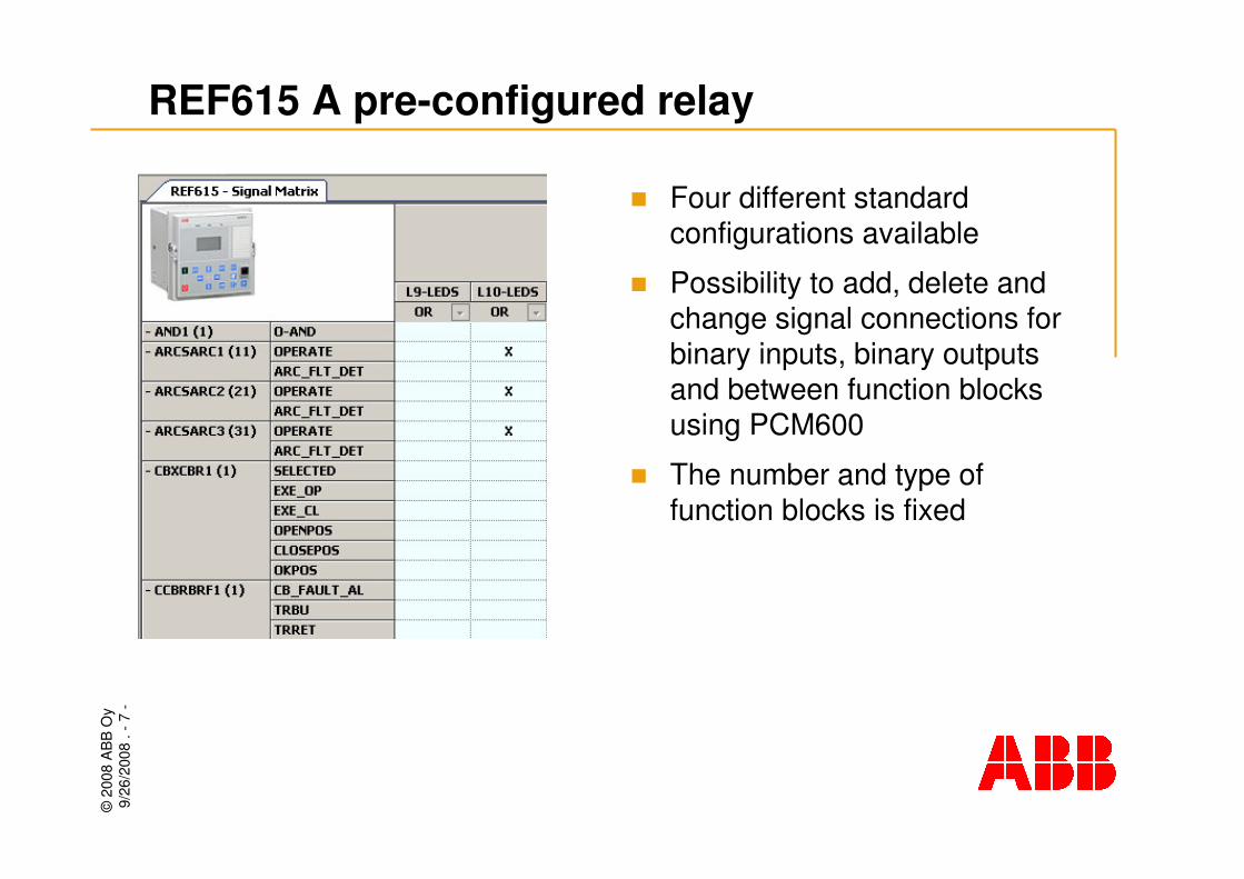
REF615 A pre-configured relay
� Four different standard configurations available
� Possibility to add, delete and change signal connections for binary inputs, binary outputs and between function blocks using PCM600
� The number and type of function blocks is fixed

©20
08 A
BB
Oy
9/26
/200
8. -
8-
REF615 Standard configurations
� Std configuration AOvercurrent and dir. E/F protection without CB condition monitoring
� Standard configuration BOvercurrent and dir. E/F protection with CB condition monitoring and interlocking schemes
� Standard configuration COvercurrent and non-dir E/Fprotection without CB condition monitoring
� Standard configuration DOvercurrent and non-dir. E/Fprotection with CB condition monitoring and interlocking schemes

©20
08 A
BB
Oy
9/26
/200
8. -
9-
REF615 Standard configurations
����������������Three-phase non-directional overcurrent, high stage, instance 2
����������������Three-phase non-directional overcurrent, high stage, instantaneous stage
--��������Directional earth-fault, low stage, instance 1
--��������Directional earth-fault, low stage, instance 2
--��������Directional earth-fault, high stage
����
����
Conf. C
Overcurrrent and non-directional earth-fault
protection
����
����
Conf. A
Overcurrrent and directional earth-fault
protection
����
����
Conf. B
����Three-phase non-directional overcurrent, high stage, instance 1
����Three-phase non-directional overcurrent, low stage
Conf. DProtection functions
Standard configurations
���� = included, ���� = optional at the time of order

©20
08 A
BB
Oy
9/26
/200
8. -
10-
REF615 Standard configurations, cont’d
����������������Negative sequence overcurrent, instance 1����������������Negative sequence overcurrent, instance 2
��������--Non-directional earth-fault, low stage��������--Non-directional earth-fault, high stage��������--Non-directional earth-fault, inst. stage��������--Non-directional sensitive earth-fault
����������������Phase discontinuity
-
-
Conf. C
Overcurrrent and non-directional earth-fault
protection
����
����
Conf. A
Overcurrrent and directional earth-fault
protection
����
����
Conf. B
-Transient/intermittent earth-fault
-Non-directional earth-fault, high-set stage(cross country earth-fault)
Conf. DProtection functions, cont’d
Standard configurations
���� = included, ���� = optional at the time of order

©20
08 A
BB
Oy
9/26
/200
8. -
11-
REF615 Standard configurations, cont’d
����������������Circuit-breaker control with basic interlocking
����-����-Circuit-breaker control with extended interlocking
����������������Three-phase inrush current detection����������������Arc protection with three sensors
Control functions
����������������Auto-reclosing of one circuit breaker
����
����
Conf. C
Overcurrrent and non-directional earth-fault
protection
����
����
Conf. A
Overcurrrent and directional earth-fault
protection
����
����
Conf. B
����Circuit-breaker failure
����Thermal overload
Conf. DProtection functions, cont’d
Standard configurations
���� = included, ���� = optional at the time of order
©20
08 A
BB
Oy
9/26
/200
8. -
12-
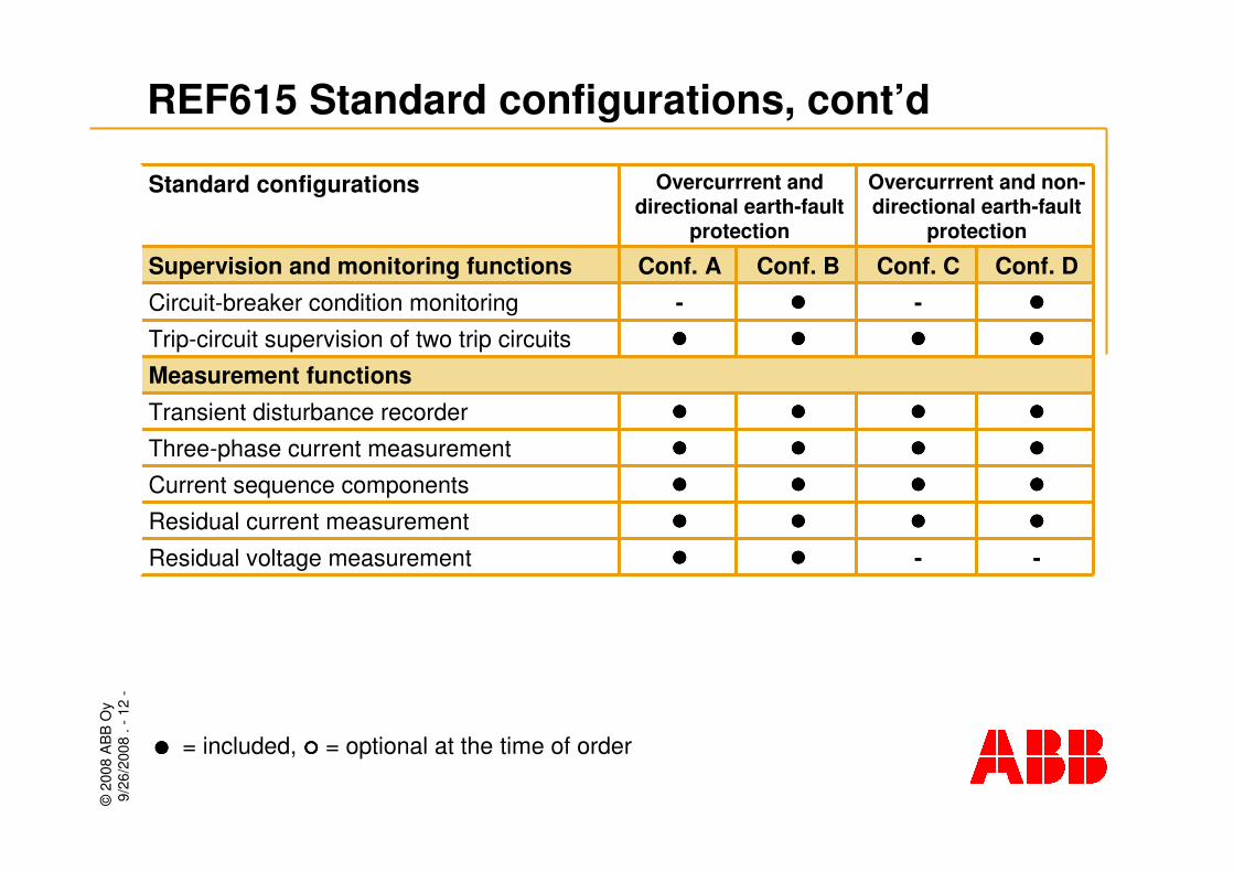
REF615 Standard configurations, cont’d
����������������Current sequence components����������������Residual current measurement
Measurement functions����������������Transient disturbance recorder����������������Three-phase current measurement
--��������Residual voltage measurement
����
-Conf. C
Overcurrrent and non-directional earth-fault
protection
����
-Conf. A
Overcurrrent and directional earth-fault
protection
����
����
Conf. B
����Trip-circuit supervision of two trip circuits
����Circuit-breaker condition monitoring
Conf. DSupervision and monitoring functions
Standard configurations
���� = included, ���� = optional at the time of order

©20
08 A
BB
Oy
9/26
/200
8. -
13-
Application
examples

©20
08 A
BB
Oy
9/26
/200
8. -
14-
REF615 applied for an overhead line feeder in an isolated or compensated network(1)
REF615 in isolated networks
� Main protection: 3I>, I0> �
� Directional E/F protection, sensitive E/F protection, core-balance CT connection
� Phase discontinuity protection
� Auto-reclosing
� Thermal overload protection
� Breaker failure protection
� Arc protection for reducedcubicle damage and increasedpersonal safety

©20
08 A
BB
Oy
9/26
/200
8. -
15-
REF615 applied for a cable feeder in an isolated or compensated network(2)
REF615 in isolated networks
� Main protection: 3I>, I0> �
� Directional E/F protection, sensitive E/F protection, transient/intermittent E/F protection, core balance CT connection
� Thermal overload protection
� Breaker failure protection
� Arc protection for reducedcubicle damage and increasedpersonal safety

©20
08 A
BB
Oy
9/26
/200
8. -
16-
REF615 for an overhead line feeder in a directly or low impedance earthed network(3)
REF615 in low-impedance earthed networks
� Main protection: 3I>, I0>
� Non-dir E/F protection, residual connection
� Phase discontinuity protection
� Breaker failure protection
� Auto-reclosing
� Arc protection for reducedcubicle damage and increased personal safety
©20
08 A
BB
Oy
9/26
/200
8. -
17-
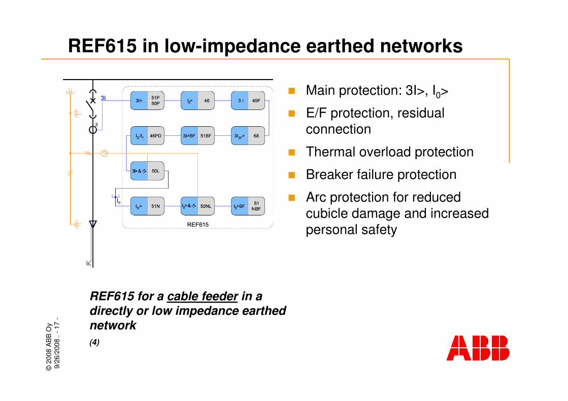
REF615 in low-impedance earthed networks
REF615 for a cable feeder in a directly or low impedance earthed network(4)
� Main protection: 3I>, I0>
� E/F protection, residualconnection
� Thermal overload protection
� Breaker failure protection
� Arc protection for reducedcubicle damage and increasedpersonal safety

©20
08 A
BB
Oy
9/26
/200
8. -
18-
Hardware
and options

©20
08 A
BB
Oy
9/26
/200
8. -
19-
REF615 Hardware modules
� [X000] Communication module (option) with or without arc-protection
� [X100] Power supply and binary output module
� [X110] Additional binary I/O module (std conf. B and D)
� [X120] Basic analog input module
� [X130] Optional binary I/O module (std conf. B and D)

©20
08 A
BB
Oy
9/26
/200
8. -
20-
Power supply and binary output modules [X100]
� Power supply options:� 48 V…250 V DC, 100 V…240 V AC,
24…60 V DC
� Four power output contacts capable of direct CB operation
� Two contacts with integrated trip circuit supervision; also to be used with double-pole operation
� The TCS can be disconnected by excluding the resistor from the trip circuit
� Two signal output contacts(1 normally open contact, 1 changeover contact)
� IRF output for self-supervision signalling
©20
08 A
BB
Oy
9/26
/200
8. -
21-
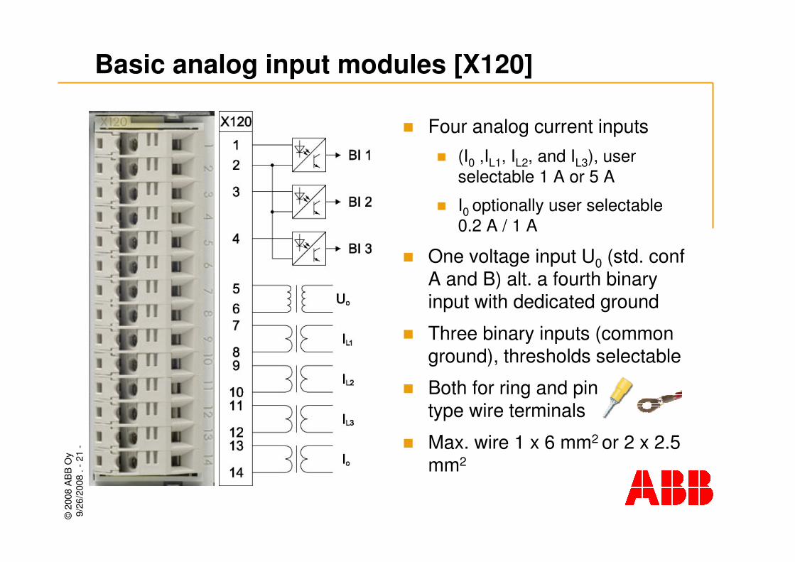
Basic analog input modules [X120]
� Four analog current inputs � (I0 ,IL1, IL2, and IL3), user
selectable 1 A or 5 A
� I0 optionally user selectable 0.2 A / 1 A
� One voltage input U0 (std. conf A and B) alt. a fourth binary input with dedicated ground
� Three binary inputs (common ground), thresholds selectable
� Both for ring and pin type wire terminals
� Max. wire 1 x 6 mm2 or 2 x 2.5 mm2

©20
08 A
BB
Oy
9/26
/200
8. -
22-
Option: Additional binary I/O module [X110]
� 7 binary inputs� 6 inputs, grouped (common
ground)
� 1 input, separated
� 3 binary outputs� 3 outputs, changeover
contacts
� Selectable binary input thresholds (17 – 186 V DC)

©20
08 A
BB
Oy
9/26
/200
8. -
23-
Option: Additional binary I/O module [X130]
� 6 binary inputs� 6 inputs, grouped (common
ground)
� 3 binary outputs� 3 outputs, changeover
contacts
� Selectable binary input thresholds (17 – 186 V DC)
©20
08 A
BB
Oy
9/26
/200
8. -
24-
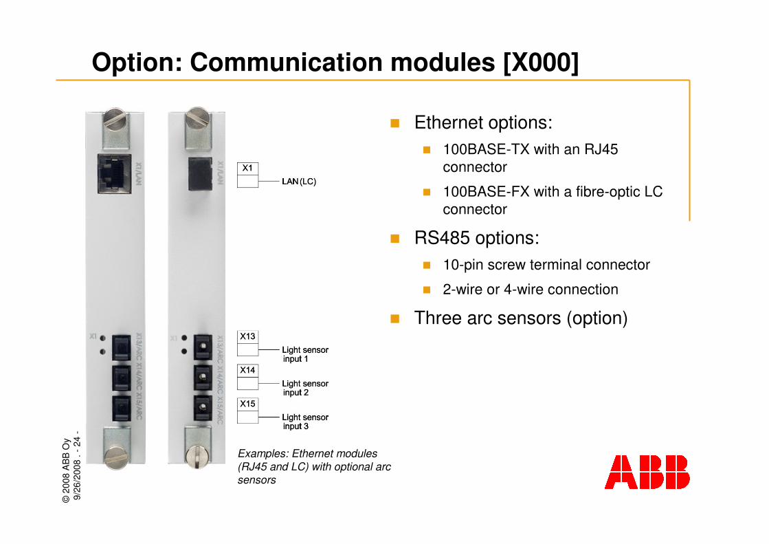
Option: Communication modules [X000]
� Ethernet options:� 100BASE-TX with an RJ45
connector
� 100BASE-FX with a fibre-optic LC connector
� RS485 options:� 10-pin screw terminal connector
� 2-wire or 4-wire connection
� Three arc sensors (option)
Examples: Ethernet modules (RJ45 and LC) with optional arc sensors

©20
08 A
BB
Oy
9/26
/200
8. -
25-
REF615 Communication modules
With arc protectionWithout arc protectionModules
Protocols
-��������-��������MODBUS TCP
����--����--MODBUS RTU/ASCII
-��������-��������IEC 61850-8-1
RS485+IRIG-B +3ARC
100BASE-FX LC +3ARC
100BASE-TX RJ45 +3ARC
RS485+IRIG-B
100BASE-FX LC
100BASE-TX RJ45
���� = supported, - = not supported
©20
08 A
BB
Oy
9/26
/200
8. -
26-
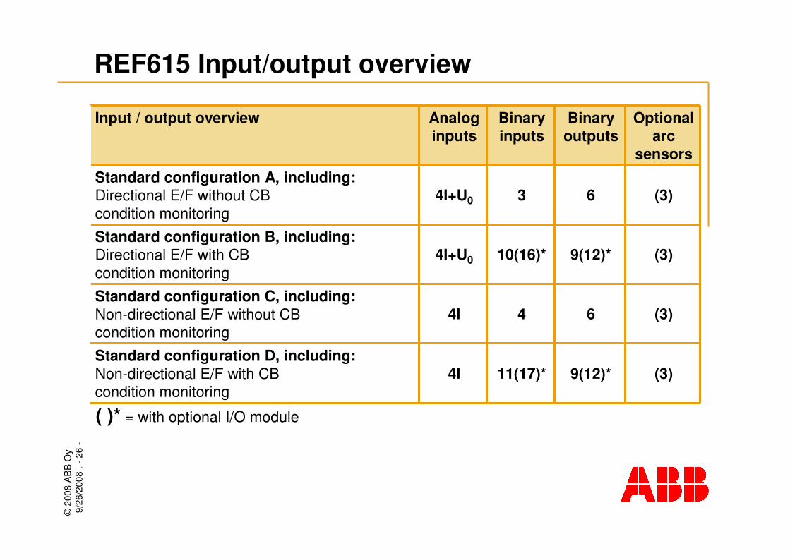
REF615 Input/output overview
(3)644IStandard configuration C, including:Non-directional E/F without CB condition monitoring
(3)9(12)*11(17)*4IStandard configuration D, including:Non-directional E/F with CB condition monitoring
9(12)*
6
Binary outputs
4I+U0
4I+U0
Analog inputs
10(16)*
3
Binary inputs
(3)Standard configuration B, including:Directional E/F with CB condition monitoring
(3)Standard configuration A, including:Directional E/F without CB condition monitoring
Optional arc
sensors
Input / output overview
( )* = with optional I/O module

©20
08 A
BB
Oy
9/26
/200
8. -
27-
Functionalityhighlights
Functionality
©20
08 A
BB
Oy
9/26
/200
8. -
28-
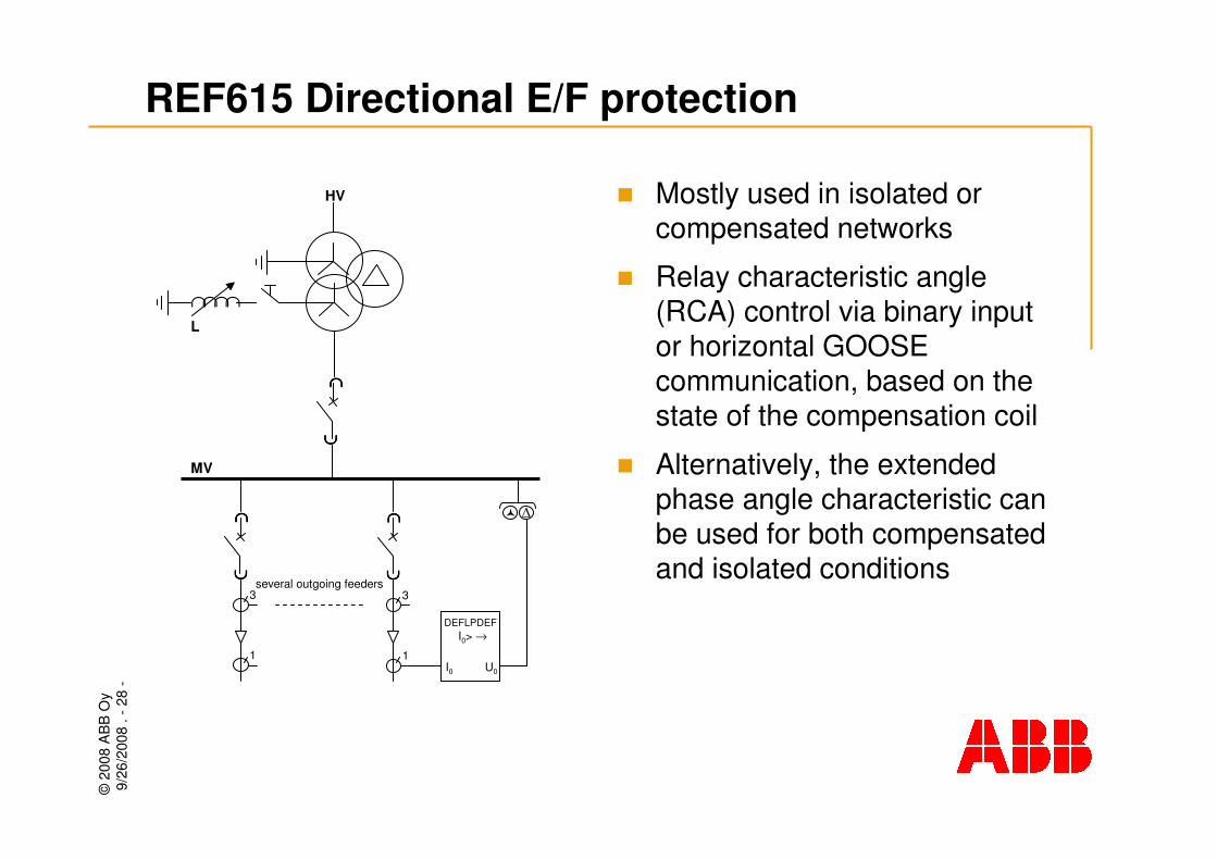
REF615 Directional E/F protection
� Mostly used in isolated or compensated networks
� Relay characteristic angle (RCA) control via binary input or horizontal GOOSE communication, based on the state of the compensation coil
� Alternatively, the extended phase angle characteristic can be used for both compensated and isolated conditions
∩∩∩∩L
HV
∩∩∩∩
∩∩∩∩
∩∩∩∩
∩∩∩∩
3
1
MV
��∩∩∩∩
∩∩∩∩
3
1
DEFLPDEF
I0 U0
I0> →
several outgoing feeders
©20
08 A
BB
Oy
9/26
/200
8. -
29-
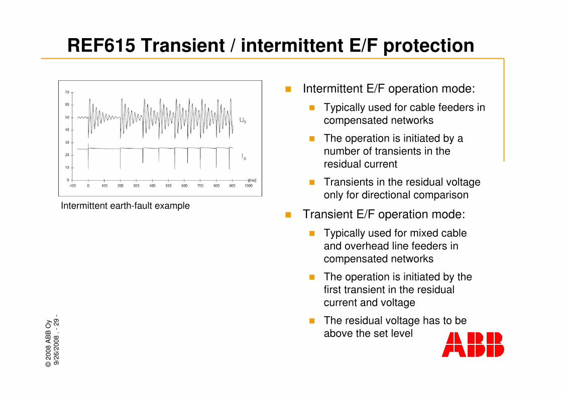
Intermittent earth-fault example
� Intermittent E/F operation mode:� Typically used for cable feeders in
compensated networks
� The operation is initiated by a number of transients in the residual current
� Transients in the residual voltage only for directional comparison
� Transient E/F operation mode:� Typically used for mixed cable
and overhead line feeders in compensated networks
� The operation is initiated by the first transient in the residual current and voltage
� The residual voltage has to be above the set level
REF615 Transient / intermittent E/F protection
©20
08 A
BB
Oy
9/26
/200
8. -
30-
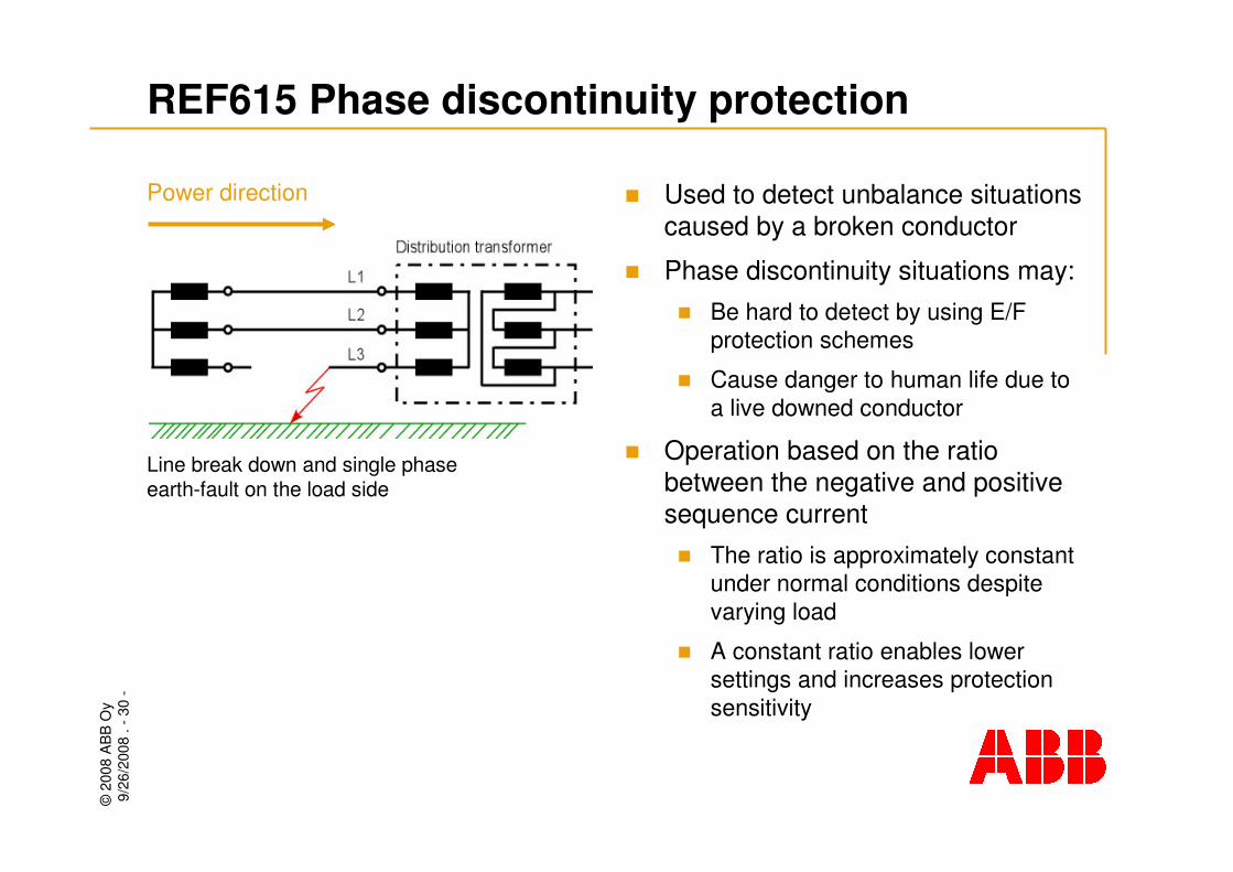
Line break down and single phase earth-fault on the load side
REF615 Phase discontinuity protection
Power direction � Used to detect unbalance situations caused by a broken conductor
� Phase discontinuity situations may:� Be hard to detect by using E/F
protection schemes
� Cause danger to human life due to a live downed conductor
� Operation based on the ratio between the negative and positive sequence current� The ratio is approximately constant
under normal conditions despite varying load
� A constant ratio enables lower settings and increases protection sensitivity
©20
08 A
BB
Oy
9/26
/200
8. -
31-
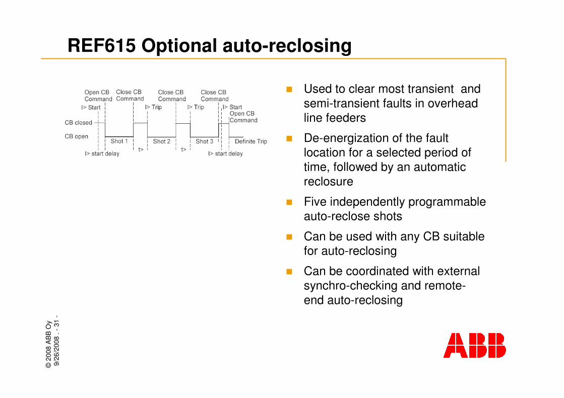
REF615 Optional auto-reclosing
� Used to clear most transient and semi-transient faults in overhead line feeders
� De-energization of the fault location for a selected period of time, followed by an automatic reclosure
� Five independently programmable auto-reclose shots
� Can be used with any CB suitable for auto-reclosing
� Can be coordinated with external synchro-checking and remote-end auto-reclosing

©20
08 A
BB
Oy
9/26
/200
8. -
32-
REF615 Control functions
� Control of one circuit breaker
� Dedicated push-buttons for opening and closing of the CB
� Interlocking schemes
� Auto-reclosing of a CB (option)
©20
08 A
BB
Oy
9/26
/200
8. -
33-
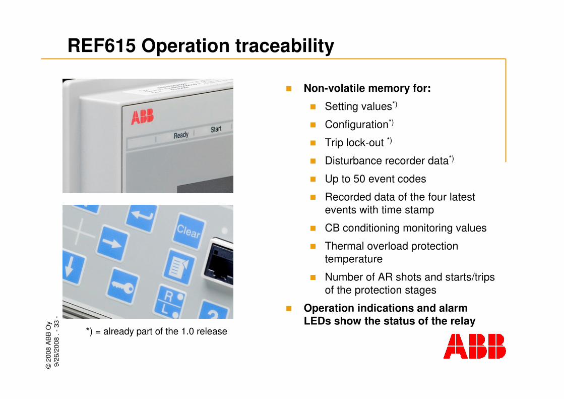
REF615 Operation traceability
� Non-volatile memory for:
� Setting values*)
� Configuration*)
� Trip lock-out *)
� Disturbance recorder data*)
� Up to 50 event codes
� Recorded data of the four latest events with time stamp
� CB conditioning monitoring values
� Thermal overload protection temperature
� Number of AR shots and starts/trips of the protection stages
� Operation indications and alarm LEDs show the status of the relay
*) = already part of the 1.0 release
©20
08 A
BB
Oy
9/26
/200
8. -
34-
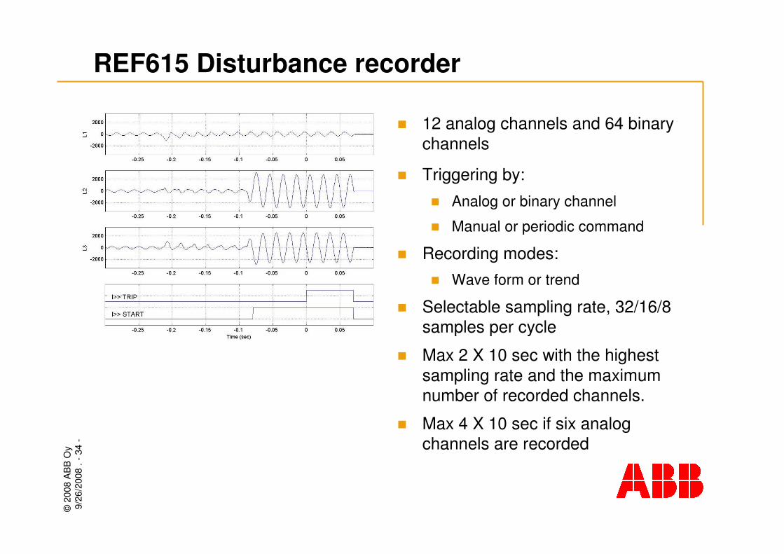
REF615 Disturbance recorder
� 12 analog channels and 64 binary channels
� Triggering by:
� Analog or binary channel
� Manual or periodic command
� Recording modes:� Wave form or trend
� Selectable sampling rate, 32/16/8 samples per cycle
� Max 2 X 10 sec with the highest sampling rate and the maximum number of recorded channels.
� Max 4 X 10 sec if six analog channels are recorded
©20
08 A
BB
Oy
9/26
/200
8. -
35-
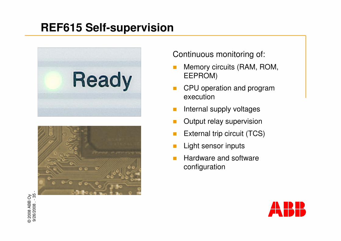
Continuous monitoring of: � Memory circuits (RAM, ROM,
EEPROM)
� CPU operation and program execution
� Internal supply voltages
� Output relay supervision
� External trip circuit (TCS)
� Light sensor inputs
� Hardware and software configuration
REF615 Self-supervision
©20
08 A
BB
Oy
9/26
/200
8. -
36-
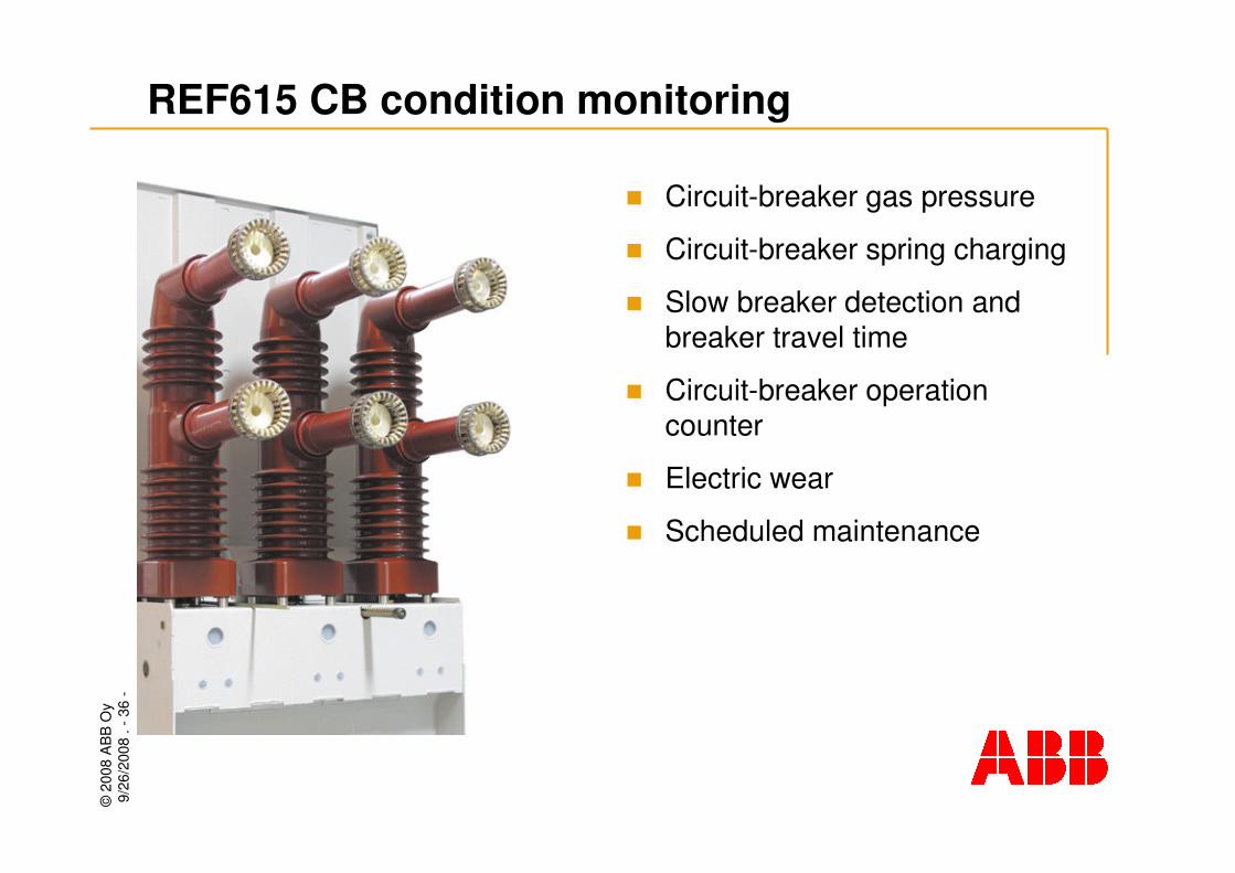
REF615 CB condition monitoring
� Circuit-breaker gas pressure
� Circuit-breaker spring charging
� Slow breaker detection and breaker travel time
� Circuit-breaker operation counter
� Electric wear
� Scheduled maintenance

©20
08 A
BB
Oy
9/26
/200
8. -
37-
REF615 Access control
� Individual user accounts with role-based access control
� Four access levels: viewer, operator, engineer and administrator level
� Applies to: � Front-panel user interface
� Web-browser based user interface
� PCM600
� Administrator programmable passwords
©20
08 A
BB
Oy
9/26
/200
8. -
38-
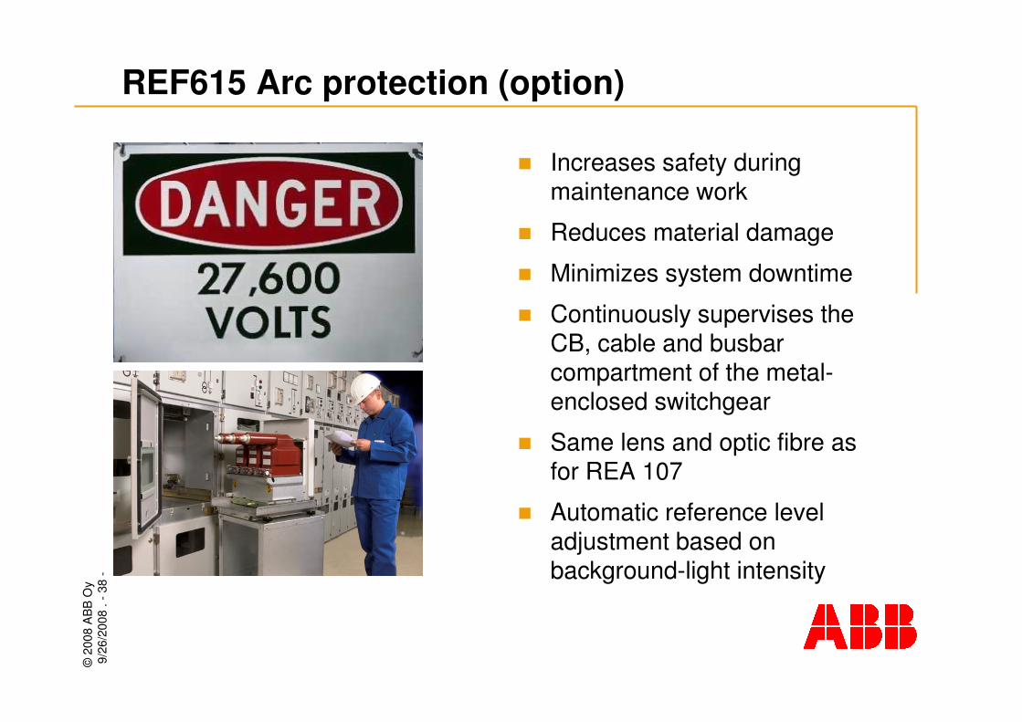
REF615 Arc protection (option)
� Increases safety during maintenance work
� Reduces material damage
� Minimizes system downtime
� Continuously supervises the CB, cable and busbar compartment of the metal-enclosed switchgear
� Same lens and optic fibre as for REA 107
� Automatic reference level adjustment based on background-light intensity
©20
08 A
BB
Oy
9/26
/200
8. -
39-
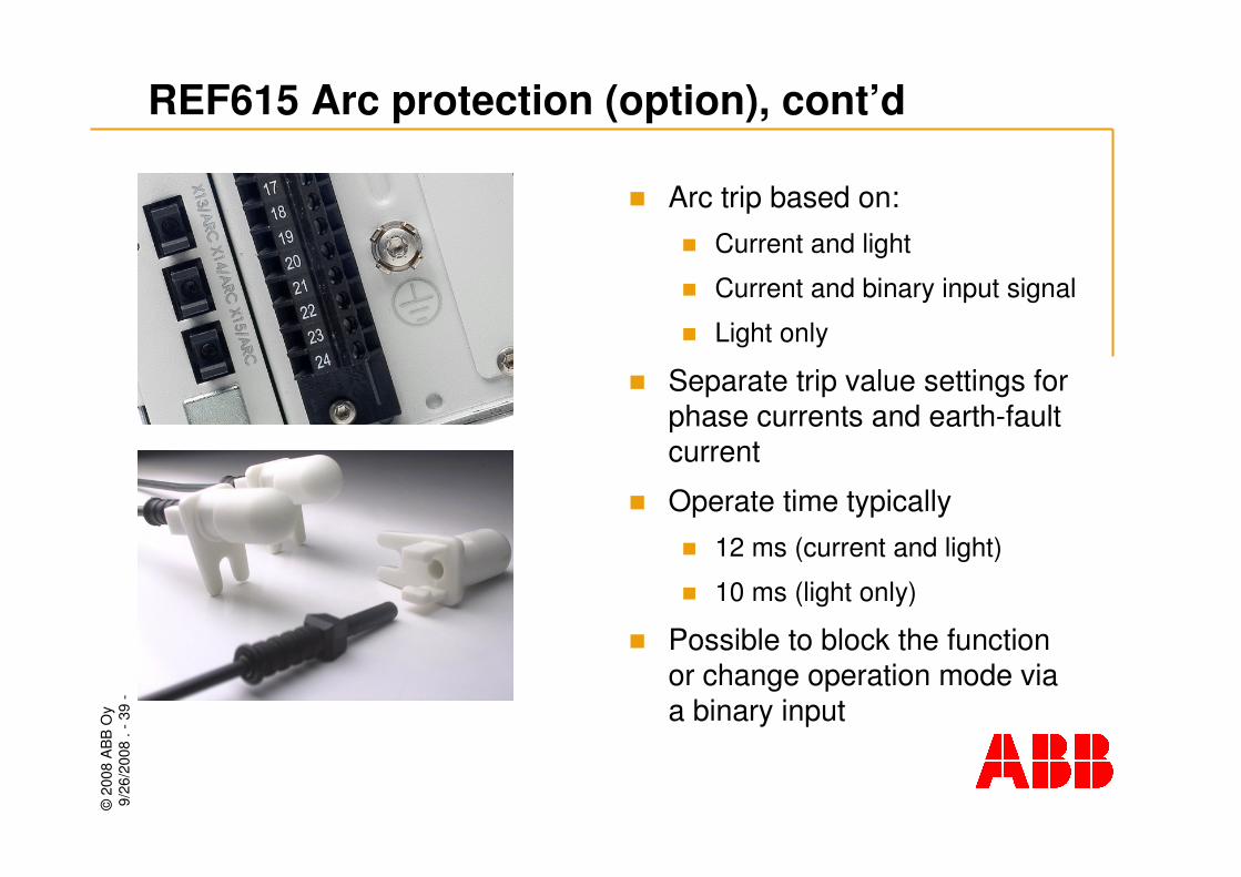
REF615 Arc protection (option), cont’d
� Arc trip based on: � Current and light
� Current and binary input signal
� Light only
� Separate trip value settings for phase currents and earth-fault current
� Operate time typically � 12 ms (current and light)
� 10 ms (light only)
� Possible to block the function or change operation mode via a binary input

©20
08 A
BB
Oy
9/26
/200
8. -
40-
REF615 Functions, codes and symbols
51N-1I0>EFLPTOCNon-directional earth-fault, low-set stage (sensitive earth-fault))
67N-IEFI0> IEFINTRPTEFTransient/intermittent earth-fault
51N-1I0>EFLPTOCNon-directional earth-fault, low-set stage
51N-2I0>>EFHPTOCNon-directional earth-fault, high-set stage
50N/51NI0>>>EFIPTOCNon-directional earth-fault, inst. stage
DEFHPDEF
DEFLPDEF
PHIPTOC
PHHPTOC
PHLPTOC
IEC 61850
67N-2I0>>Directional earth-fault, high-set stage
67N-1I0>Directional earth-fault, low-set stage
50P/51P3I>>>Three-phase non-directional overcurrent, instantaneous stage
51P-23I>>Three-phase non-directional overcurrent, high stage
51P-13I>Three-phase non-directional overcurrent, low stage
ANSIIEC 60617Protection functions O/C & E/F
©20
08 A
BB
Oy
9/26
/200
8. -
41-
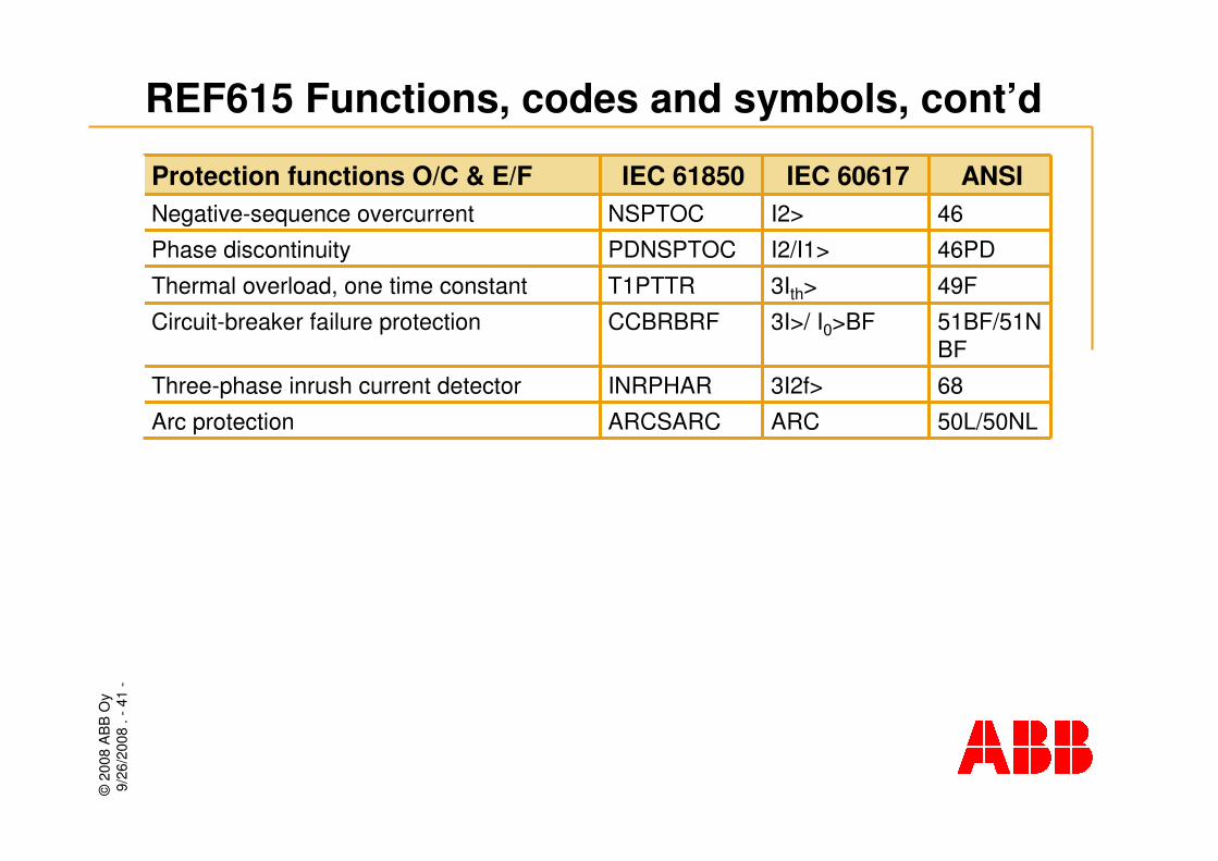
REF615 Functions, codes and symbols, cont’d
ARCSARC
INRPHAR
CCBRBRF
T1PTTR
PDNSPTOC
NSPTOC
IEC 61850
50L/50NLARCArc protection
683I2f>Three-phase inrush current detector
51BF/51NBF
3I>/ I0>BFCircuit-breaker failure protection
49F3Ith>Thermal overload, one time constant
46PDI2/I1>Phase discontinuity
46I2>Negative-sequence overcurrent
ANSIIEC 60617Protection functions O/C & E/F
©20
08 A
BB
Oy
9/26
/200
8. -
42-
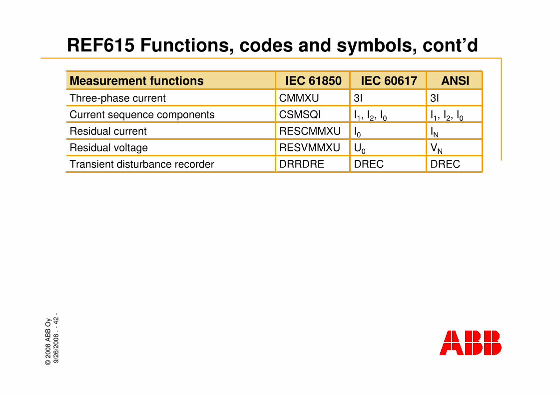
REF615 Functions, codes and symbols, cont’d
DRRDRE
RESVMMXU
RESCMMXU
CSMSQI
CMMXU
IEC 61850
DRECDRECTransient disturbance recorder
VNU0Residual voltage
INI0Residual current
I1, I2, I0I1, I2, I0Current sequence components
3I3IThree-phase current
ANSIIEC 60617Measurement functions

©20
08 A
BB
Oy
9/26
/200
8. -
43-
Communication
©20
08 A
BB
Oy
9/26
/200
8. -
44-
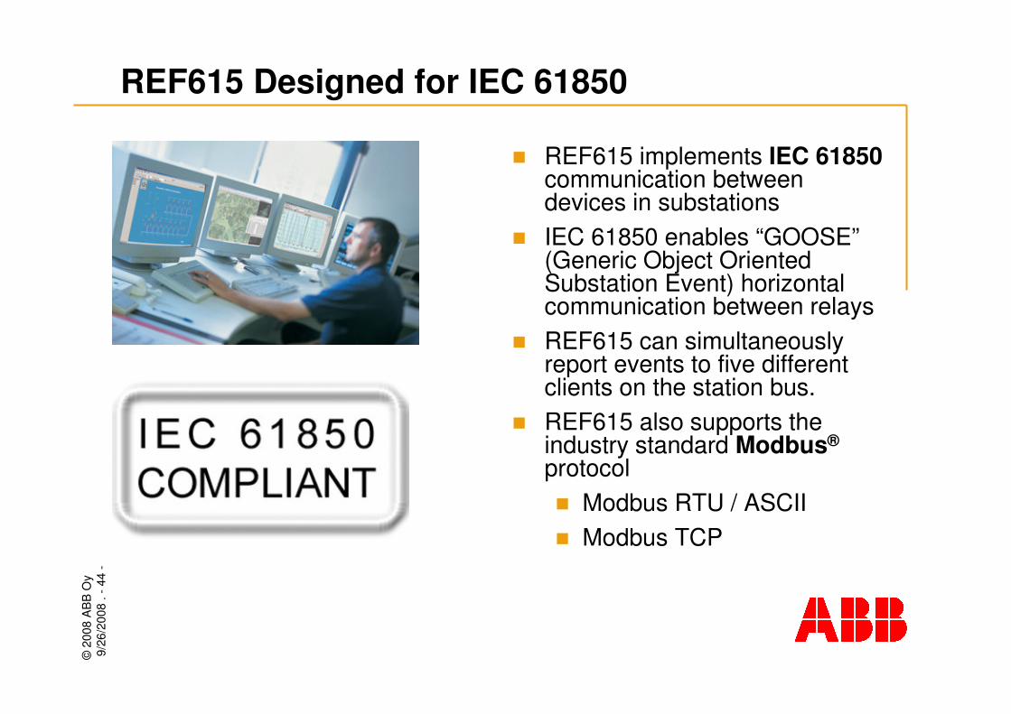
� REF615 implements IEC 61850communication between devices in substations
� IEC 61850 enables “GOOSE”(Generic Object Oriented Substation Event) horizontal communication between relays
� REF615 can simultaneously report events to five different clients on the station bus.
� REF615 also supports the industry standard Modbus®
protocol� Modbus RTU / ASCII� Modbus TCP
REF615 Designed for IEC 61850
©20
08 A
BB
Oy
9/26
/200
8. -
45-
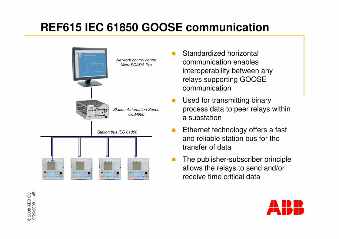
REF615 IEC 61850 GOOSE communication
� Standardized horizontal communication enables interoperability between any relays supporting GOOSE communication
� Used for transmitting binary process data to peer relays within a substation
� Ethernet technology offers a fast and reliable station bus for the transfer of data
� The publisher-subscriber principle allows the relays to send and/or receive time critical data
Station Automation SeriesCOM600
Station bus IEC 61850
Network control centreMicroSCADA Pro

©20
08 A
BB
Oy
9/26
/200
8. -
46-
REF615 GOOSE communication benefits
� Expandability and flexibility:� Flexible modifications without
changing the wiring between the relays
� No relay I/Os are needed for the transer of data between the relays
� Reduced wiring between the relays
� Possible to add functionality like interlocking schemes between the cubicles in existing switchgear (retrofit)
� Supervised data transfer (connection and data quality)
� REF615 meets the highest GOOSE performance requirements defined by the IEC 61850 standard

©20
08 A
BB
Oy
9/26
/200
8. -
47-
REF615 GOOSE - Arc protection
1.
2.
3.
1.
2.
3.
Relay B
Relay A
GOOSE message
� Both relay A (incoming feeder) and relay B (outgoing feeder) are equipped with three arc sensors
� Relay B detects an arc in the busbar compartment via sensor 1 and sends a related GOOSE message to relay A
� After receiving the GOOSE message relay A checks the current level and issues a trip command to breaker A
� GOOSE communication enables fast and stationwide supervised arc protection schemes
Breaker flash

©20
08 A
BB
Oy
9/26
/200
8. -
48-
REF615 GOOSE - Breaker failure protection
Relay B
Relay A
Relay C
Breaker Failure Protection Operates
� On detecting a fault on the outgoing feeder relay B sends a trip command to CB “B” and initiates the CB failure protection function
� CB “B” fails to open
� The CB failure protection function of relay B sends a trip command to relay A using GOOSE
� The use of GOOSE communication eliminates the need for dedicated wiring
� CB failure protection can be added without renewing the wiring and with minimum disturbance to the process
GOOSEmessage
©20
08 A
BB
Oy
9/26
/200
8. -
49-
� Ethernet-based time synchronization:� SNTP (Simple Network
Time Protocol)
� With special time synchronization wiring:� IRIG-B (Inter-Range
Instrumentation Group - Time Code Format B
� Time stamp resolution:� +/- 1 ms
REF615 Time synchronization methods
©20
08 A
BB
Oy
9/26
/200
8. -
50-
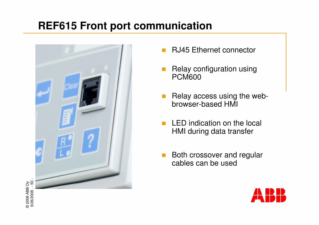
� RJ45 Ethernet connector
� Relay configuration using PCM600
� Relay access using the web-browser-based HMI
� LED indication on the local HMI during data transfer
� Both crossover and regular cables can be used
REF615 Front port communication

©20
08 A
BB
Oy
9/26
/200
8. -
51-
Mechanical
design
©20
08 A
BB
Oy
9/26
/200
8. -
52-
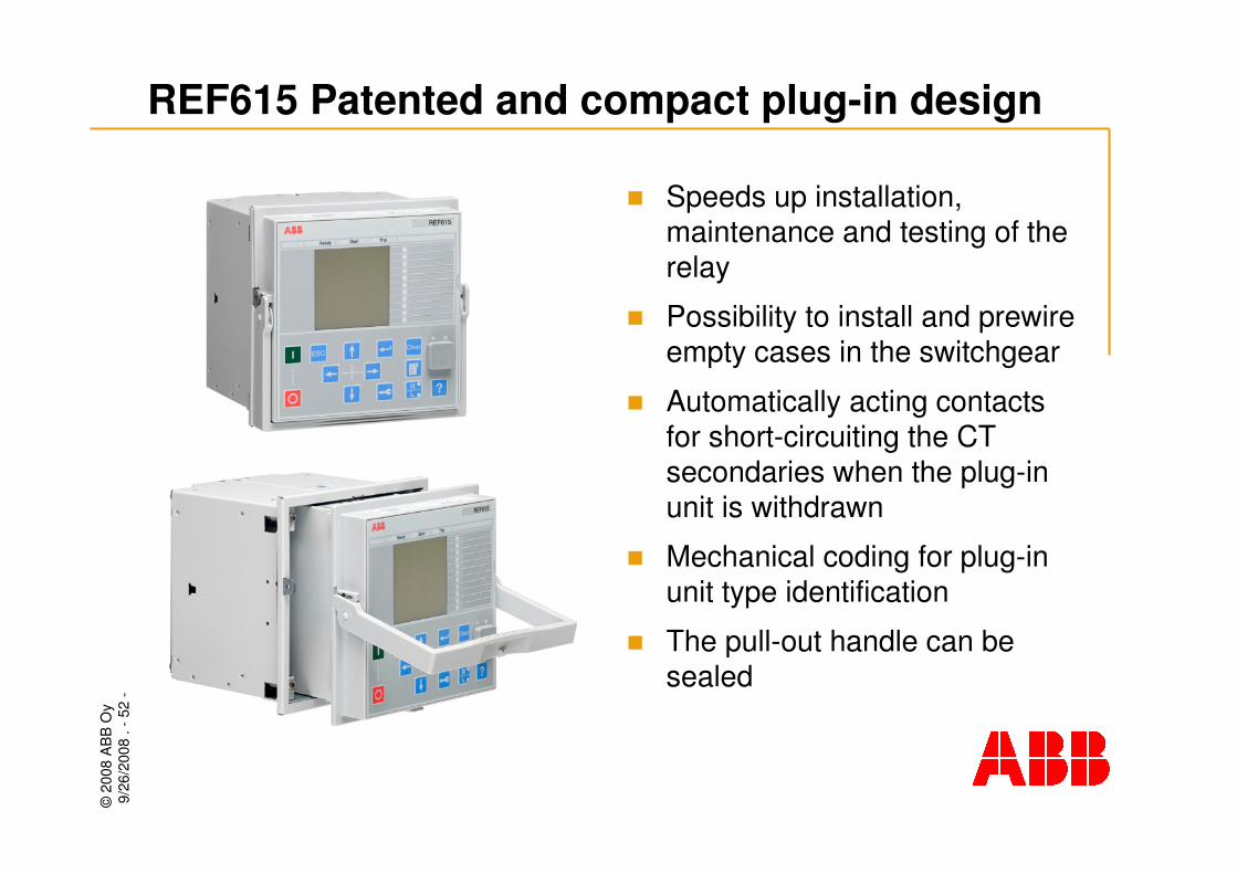
� Speeds up installation, maintenance and testing of the relay
� Possibility to install and prewireempty cases in the switchgear
� Automatically acting contacts for short-circuiting the CT secondaries when the plug-in unit is withdrawn
� Mechanical coding for plug-in unit type identification
� The pull-out handle can be sealed
REF615 Patented and compact plug-in design

©20
08 A
BB
Oy
9/26
/200
8. -
53-
REF615 Relay case and plug-in unit
� Height: frame 177 mm, case 164 mm
� Width: frame 177 mm (4U), case 160 mm
� Depth: case 155 mm
IP classification
Rear sideIP20
Top, sides and bottom
IP40
When panel-mounted
IP54

©20
08 A
BB
Oy
9/26
/200
8. -
54-
� Flush mounting� The same cut-out on the
cubicle front as for REF610 (height: 161.5 ±1, width: 165.5 ±1)
� Semi-flush mounting� With a 50 mm rising frame
� Semi-flush mounting in a 25°angle� With special accessories
REF615 Mounting alternatives
©20
08 A
BB
Oy
9/26
/200
8. -
55-
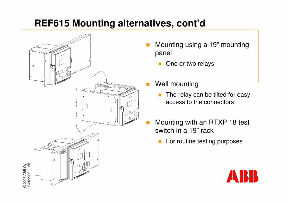
� Mounting using a 19” mounting panel� One or two relays
� Wall mounting� The relay can be tilted for easy
access to the connectors
� Mounting with an RTXP 18 test switch in a 19” rack� For routine testing purposes
REF615 Mounting alternatives, cont’d

©20
08 A
BB
Oy
9/26
/200
8. -
56-
Front panel HMI

©20
08 A
BB
Oy
9/26
/200
8. -
57-
REF615 Front panel HMI
4 x 16 characterdisplay (LCD)
Front communication port
Three dedicated LEDs: Ready, Start,Trip
11 programmable LEDs
CB Control, OPEN and CLOSE buttons
ESC button
Navigation buttons
ENTER buttonCLEAR button
MENU button
LOCAL/REMOTE button, HELP
AUTHORIZATION

©20
08 A
BB
Oy
9/26
/200
8. -
58-
REF615 LCD display options
� Small LCD, mono-spaced 4 x 20 characters, variable width 4 x 8 (or more) characters
� Large LCD, mono-spaced 10 x 20 characters, variable width 8 x 8 (or more) characters
� Background light with power-saving mode
©20
08 A
BB
Oy
9/26
/200
8. -
59-
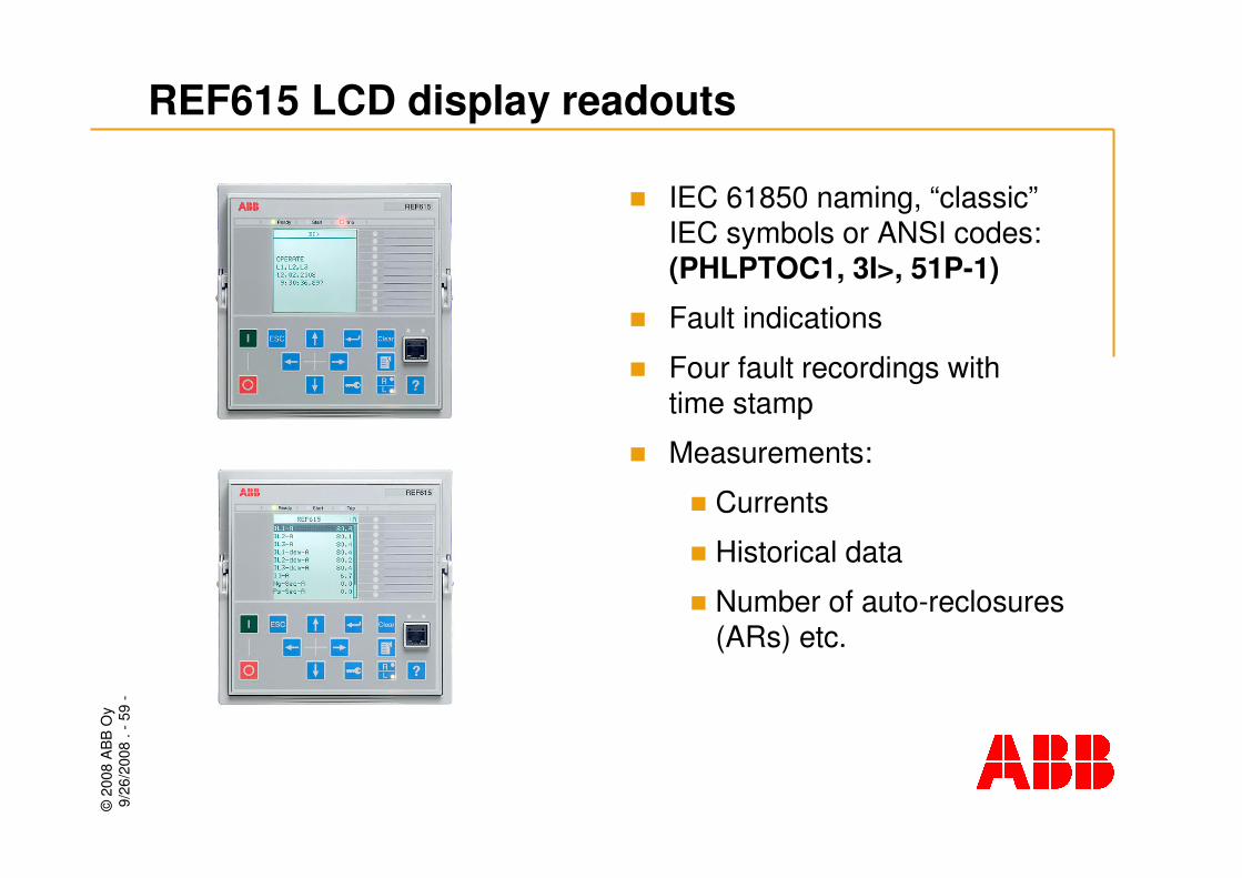
� IEC 61850 naming, “classic”IEC symbols or ANSI codes: (PHLPTOC1, 3I>, 51P-1)
� Fault indications
� Four fault recordings with time stamp
� Measurements:
� Currents
� Historical data
� Number of auto-reclosures(ARs) etc.
REF615 LCD display readouts

©20
08 A
BB
Oy
9/26
/200
8. -
60-
� Name or code of protected objects
� Settings in 4 setting groups
� Configurations such as protocol settings etc.
� Product information, serial number, software version, identification etc.
REF615 LCD display readouts, cont’d

©20
08 A
BB
Oy
9/26
/200
8. -
61-
Tools

©20
08 A
BB
Oy
9/26
/200
8. -
62-
REF615 Tools
9.2 SP1 or laterMicroSCADA Pro
3.2 or laterStation Automation Series COM600
IE 7.0 or laterWeb-browser-based user interface
1.2 or laterREF615 connectivity package
2.0 SP1 or laterPCM600VersionConfiguration, setting and SA system tools

©20
08 A
BB
Oy
9/26
/200
8. -
63-
PCM600 Management tool
� A common tool for new and existing protection relays and terminals
� Relay-specific connectivity packages enable the use PCM600 for different ABB protection relays and terminals
� Supports IEC 61850
� GOOSE messaging configuration (PCM600 Engineering Pro)
� Relay interaction using:� Corporate LAN/WAN
� The relay’s communication port
©20
08 A
BB
Oy
9/26
/200
8. -
64-
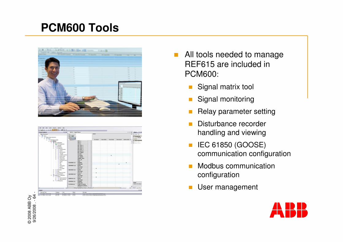
PCM600 Tools
� All tools needed to manage REF615 are included in PCM600:
� Signal matrix tool
� Signal monitoring
� Relay parameter setting
� Disturbance recorder handling and viewing
� IEC 61850 (GOOSE) communication configuration
� Modbus communication configuration
� User management
©20
08 A
BB
Oy
9/26
/200
8. -
65-
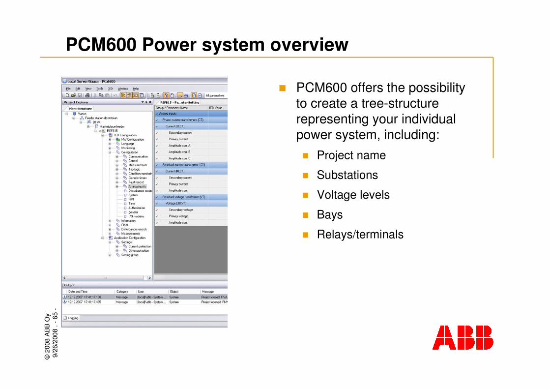
PCM600 Power system overview
� PCM600 offers the possibility to create a tree-structure representing your individual power system, including:� Project name
� Substations
� Voltage levels
� Bays
� Relays/terminals

©20
08 A
BB
Oy
9/26
/200
8. -
66-
� Local or remote relay access using an IE 7.0 (or later) web browser
� Disabled by default, enabled by PCM600 or the local front-panel interface
� Functions:� Viewing of alarm LEDs and event
lists
� Saving of event data
� Parameter setting
� Signal monitoring
� Measurement viewing
� Phasor diagram viewing
� User access level authentication
REF615 Web-browser based user interface

©20
08 A
BB
Oy
9/26
/200
8. -
67-
Conclusions

©20
08 A
BB
Oy
9/26
/200
8. -
68-
REF615 Product summary
� IEC 61850 communication including GOOSE messaging
� Comprehensive earth-fault protection functionality
� Arc protection, three sensors
� CB control buttons on the HMI
� All I/Os are fully matrixed, thus enabling optimal use
� Rapid set-up and commissioning, pre-configured relays
� Patented plug-in / draw-out design
� Optimized size - suitable for retrofit purposes
� Versatile tools
©20
08 A
BB
Oy
9/26
/200
8. -
69-
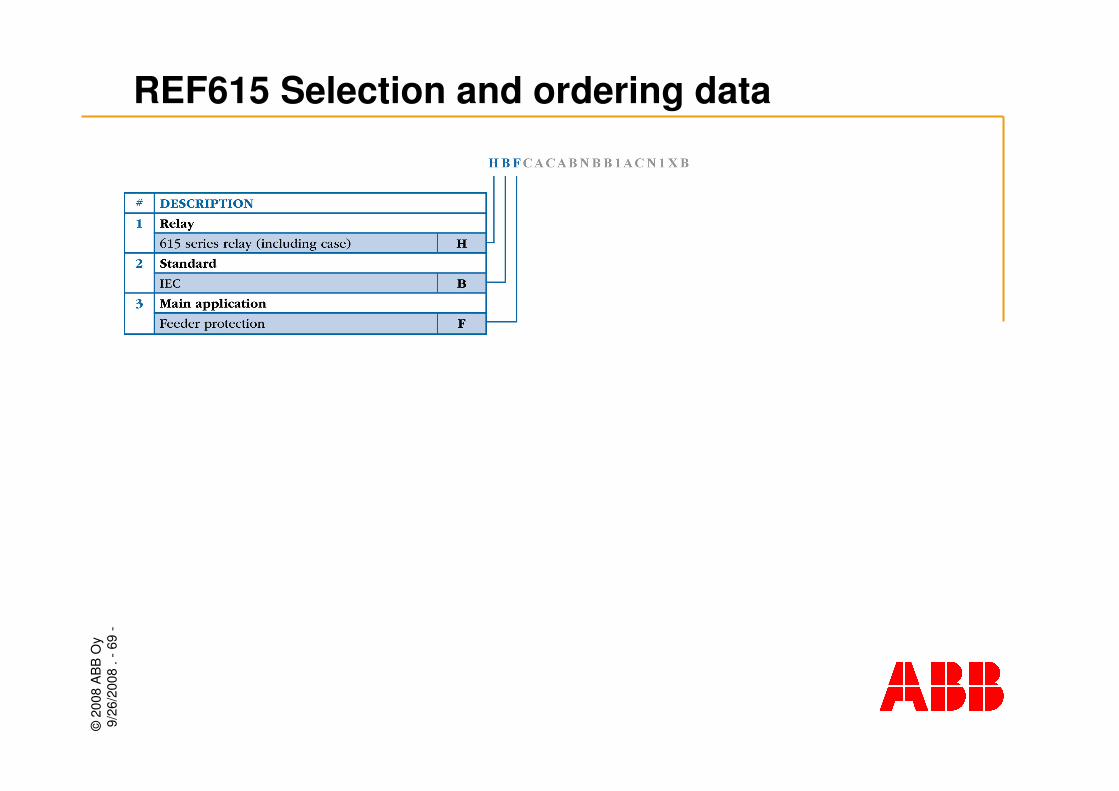
REF615 Selection and ordering data

©20
08 A
BB
Oy
9/26
/200
8. -
70-
REF615 Selection and ordering data

©20
08 A
BB
Oy
9/26
/200
8. -
71-
REF615 Selection and ordering data

©20
08 A
BB
Oy
9/26
/200
8. -
72-
REF615 Selection and ordering data

©20
08 A
BB
Oy
9/26
/200
8. -
73-
REF615 Selection and ordering data

©20
08 A
BB
Oy
9/26
/200
8. -
74-
REF615 Product pages on the web
www.abb.com/substationautomation

©20
08 A
BB
Oy
9/26
/200
8. -
75-
Please visit ourwebsite for the latest product information
www.abb.com/substationautomation
