feeder protection and control ref615 dnp3 point … · relion® 615 series feeder protection and...
TRANSCRIPT

Relion® 615 series
Feeder Protection and ControlREF615DNP3 Point List Manual

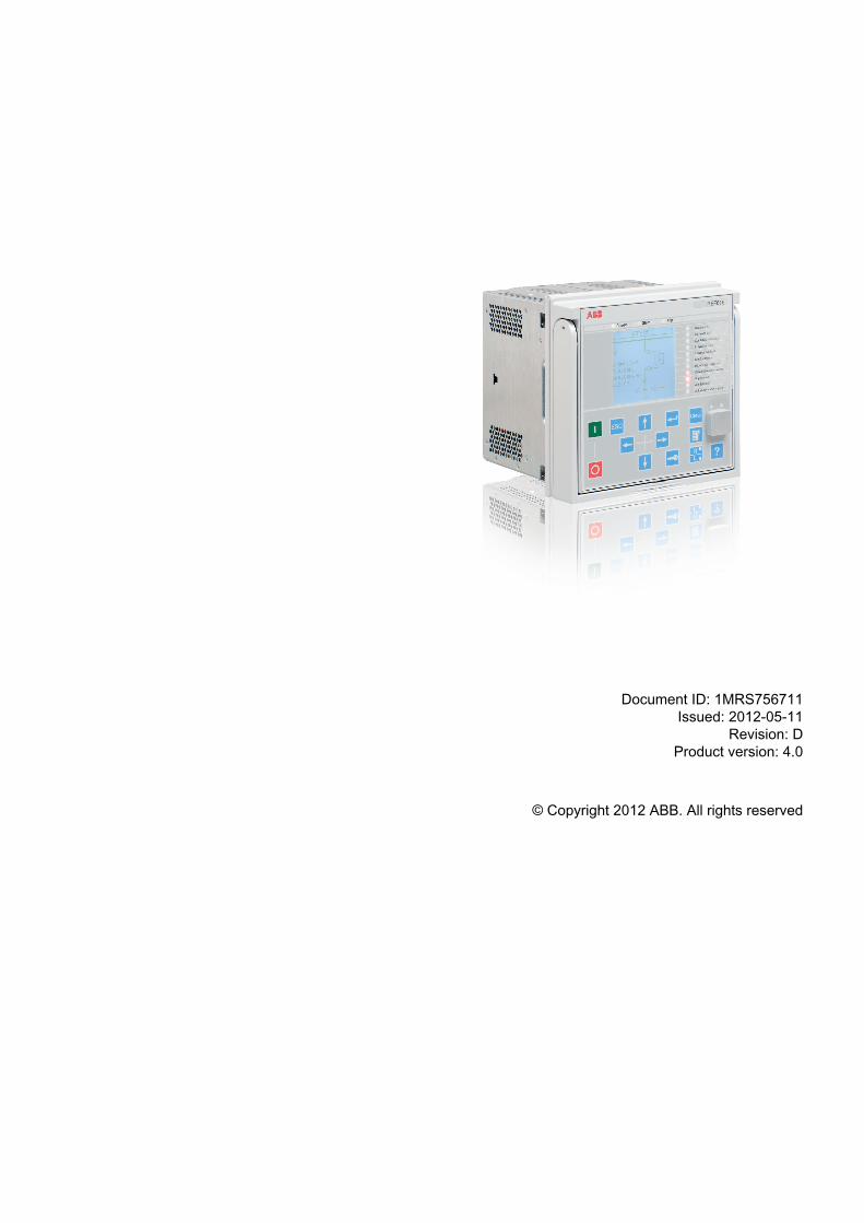
Document ID: 1MRS756711Issued: 2012-05-11
Revision: DProduct version: 4.0
© Copyright 2012 ABB. All rights reserved

CopyrightThis document and parts thereof must not be reproduced or copied without writtenpermission from ABB, and the contents thereof must not be imparted to a thirdparty, nor used for any unauthorized purpose.
The software or hardware described in this document is furnished under a licenseand may be used, copied, or disclosed only in accordance with the terms of suchlicense.
TrademarksABB and Relion are registered trademarks of the ABB Group. All other brand orproduct names mentioned in this document may be trademarks or registeredtrademarks of their respective holders.
WarrantyPlease inquire about the terms of warranty from your nearest ABB representative.
http://www.abb.com/substationautomation

DisclaimerThe data, examples and diagrams in this manual are included solely for the conceptor product description and are not to be deemed as a statement of guaranteedproperties. All persons responsible for applying the equipment addressed in thismanual must satisfy themselves that each intended application is suitable andacceptable, including that any applicable safety or other operational requirementsare complied with. In particular, any risks in applications where a system failure and/or product failure would create a risk for harm to property or persons (including butnot limited to personal injuries or death) shall be the sole responsibility of theperson or entity applying the equipment, and those so responsible are herebyrequested to ensure that all measures are taken to exclude or mitigate such risks.
This document has been carefully checked by ABB but deviations cannot becompletely ruled out. In case any errors are detected, the reader is kindly requestedto notify the manufacturer. Other than under explicit contractual commitments, inno event shall ABB be responsible or liable for any loss or damage resulting fromthe use of this manual or the application of the equipment.

ConformityThis product complies with the directive of the Council of the EuropeanCommunities on the approximation of the laws of the Member States relating toelectromagnetic compatibility (EMC Directive 2004/108/EC) and concerningelectrical equipment for use within specified voltage limits (Low-voltage directive2006/95/EC). This conformity is the result of tests conducted by ABB inaccordance with the product standards EN 50263 and EN 60255-26 for the EMCdirective, and with the product standards EN 60255-1 and EN 60255-27 for the lowvoltage directive. The product is designed in accordance with the internationalstandards of the IEC 60255 series.

Table of contents
Section 1 Introduction.......................................................................7This manual........................................................................................7Intended audience..............................................................................7Product documentation.......................................................................7
Product documentation set............................................................7Document revision history.............................................................8Related documentation..................................................................8
Symbols and conventions...................................................................9Symbols.........................................................................................9Document conventions..................................................................9Functions, codes and symbols....................................................10
Section 2 DNP3 data mappings.....................................................13Overview...........................................................................................13Supported functions..........................................................................13Point list for REF615 Ver.4.0 FE01-09.............................................15
Binary inputs................................................................................15LD0.ARCSARC1 Fault arc protection stage 1........................16LD0.ARCSARC2 Fault arc protection stage 2........................16LD0.ARCSARC3 Fault arc protection stage 3........................16CTRL.Cxxxxx1 Circuit breaker (1) CB object and failureprotection................................................................................16CTRL.Dxxxxx1 Controllable disconnector (1)........................17CTRL.Dxxxxx2 Controllable disconnector (2)........................17CTRL.Exxxxx1 Controllable earth switch (1)..........................18CTRL.CCRDIF1 Current circuit failure protection..................18LD0.CMHAI1 Power quality - current total demanddistortion.................................................................................18LD0.CMMXU1 Phase currents (1) limit supervision...............18LD0.DARREC1 Autorecloser.................................................19LD0.DEFHPDEF1 Directional earth-fault protection -high stage 1............................................................................19LD0.DEFLPDEF1 Directional earth-fault protection - lowstage 1....................................................................................20LD0.DEFLPDEF2 Directional earth-fault protection - lowstage 2....................................................................................20LD0.DPHLPDOC1 Three-phase directional overcurrentprotection - low stage (1)........................................................20LD0.DPHLPDOC2 Three-phase directional overcurrentprotection - low stage (2)........................................................20
Table of contents
REF615 1Point List Manual
LD0.DPHHPDOC1 Three-phase directional overcurrentprotection - high stage (1)......................................................21LD0.EFHPTOC1 Non-directional earth-fault andsensitive earth-fault protection - high stage 1.........................21LD0.EFIPTOC1 Non-directional earth-fault and sensitiveearth-fault protection - instantaneous stage 1........................21LD0.EFLPTOC1 Non-directional earth-fault andsensitive earth-fault protection - low stage 1..........................21LD0.EFLPTOC2 Non-directional earth-fault andsensitive earth-fault protection - low stage 2..........................22LD0.EFPADM1 Admittance-based earth-fault protection(1)...........................................................................................22LD0.EFPADM2 Admittance-based earth-fault protection(2)...........................................................................................22LD0.EFPADM3 Admittance-based earth-fault protection(3)...........................................................................................22LD0.FRPFRQ1 Frequency protection (1)...............................22LD0.FRPFRQ2 Frequency protection (2)...............................23LD0.FRPFRQ3 Frequency protection (3)...............................23LD0.HAEFPTOC1 Harmonics-based earth-faultprotection................................................................................23LD0.INPHAR1 Three-phase inrush detection........................24LD0.INTRPTEF1 Transient/intermittent earth-faultprotection................................................................................24LD0.LEDGGIO1 LHMI LED indications..................................24LD0.LEDPTRC1 Global protection signals.............................24CTRL.LLN0 Local/remote state (also present in DNP IIN-bits).........................................................................................25LD0.LLN0 Settings supervision..............................................25LD0.MVGAPC1 Multipurpose binary inputs (1)......................25LD0.MVGAPC2 Multipurpose binary inputs (2)......................26LD0.NSPTOC1 Negative-sequence overcurrentprotection (1)..........................................................................26LD0.NSPTOC2 Negative-sequence overcurrentprotection (2)..........................................................................26LD0.NSPTOV1 Negative-sequence overvoltageprotection - stage 1.................................................................26LD0.PDNSPTOC1 Phase discontinuity protection.................27LD0.PHHPTOC1 Phase overcurrent protection - highstage 1 ...................................................................................27LD0.PHHPTOC2 Phase overcurrent protection - highstage 2 ...................................................................................27LD0.PHIPTOC1 Phase overcurrent protection -instantaneous stage 1 ...........................................................27LD0.PHLPTOC1 Phase overcurrent protection - lowstage 1 ...................................................................................27
Table of contents
2 REF615Point List Manual
LD0.PHPTOV1 Phase overvoltage protection - stage 1........28LD0.PHPTOV2 Phase overvoltage protection - stage 2........28LD0.PHPTOV3 Phase overvoltage protection - stage 3........28LD0.PHPTUV1 Phase undervoltage protection - stage1.............................................................................................28LD0.PHPTUV2 Phase undervoltage protection - stage2.............................................................................................28LD0.PHPTUV3 Phase undervoltage protection - stage3.............................................................................................29LD0.PSPTUV1 Positive-sequence undervoltageprotection - stage 1.................................................................29LD0.PH1QVVR1 PQ - Voltage variation signals....................29DR.RDRE1 Disturbance recorder..........................................29LD0.RESCMMXU1 Residual current limit supervision...........29LD0.RESVMMXU1 Residual voltage limit supervision...........30LD0.ROVPTOV1 Residual overvoltage protection (1)...........30LD0.ROVPTOV2 Residual overvoltage protection (2)...........30LD0.ROVPTOV3 Residual overvoltage protection (3)...........30LD0.SECRSYN1 Synchrocheck ............................................30LD0.SEQRFUF1 Fuse failure protection................................31LD0.SPCGGIO2 Multipurpose binary outputs - status(2)...........................................................................................31LD0.SSCBR1 Circuit-breaker condition monitoring................31LD0.T1PTTR1 Thermal protection (1)....................................32LD0.TCSSCBR1 Trip circuit supervision (1)..........................32LD0.TCSSCBR2 Trip circuit supervision (2)..........................32LD0.TRPPTRC1 Global conditioning (1)................................32LD0.TRPPTRC2 Global conditioning (2)................................33LD0.VMHAI1 PQ - Voltage total harmonic distortion..............33LD0.VMMXU1 Three-phase voltage limit supervision............33LD0.WPWDE1 Wattmetric-based earth-fault protection(1)...........................................................................................33LD0.WPWDE2 Wattmetric-based earth-fault protection(2)...........................................................................................33LD0.WPWDE3 Wattmetric-based earth-fault protection(3)...........................................................................................34LD0.XAGGIO130 Physical I/O...............................................34LD0.XGGIO100 Physical I/O..................................................34LD0.XGGIO110 Physical I/O..................................................34LD0.XGGIO120 Physical I/O..................................................35LD0.XGGIO130 Physical I/O..................................................35
Binary outputs..............................................................................36CTRL.CBCSWI1 Circuit breaker control ...............................36CTRL.DCCSWI1 Controllable disconnector (1) control .........36
Table of contents
REF615 3Point List Manual
CTRL.DCCSWI2 Controllable disconnector (2) control..........36CTRL.ESCSWI2 Controllable earth switch (1) control ..........36LD0.DARREC1 Autoreclosing reset signals...........................37LD0.DNPGGIO1 Parameter setting group control.................37LD0.LLN0/LPHD1 Reset indications and LEDs, resetdevice.....................................................................................37LD0.PEMMXU1 Reset accumulated energy values...............37DR.RDRE1 Disturbance recorder..........................................38LD0.SPCGGIO1 Multipurpose binary outputs (1)..................38LD0.SPCGGIO2 Multipurpose binary outputs (2)..................38LD0.SRGAPC1 Multipurpose binary outputs - flip-flopresets (1)................................................................................39LD0.SRGAPC2 Multipurpose binary outputs - flip-flopresets (2)................................................................................40LD0.SSCBR1 Reset signals of CB condition monitoring........40
Analog inputs...............................................................................40CTRL.CBCSWI1 CB 4-pole (2 bit) position value..................41LD0.CMMXU1 Phase currents (1)..........................................41LD0.CSMSQI1 Sequence of currents....................................41LD0.DARREC1 Autoreclosing values....................................41CTRL.DCSXSWI1 Disconnector 1, 4-pole (2 bit)position values........................................................................41CTRL.DCSXSWI2 Disconnector 2, 4-pole (2 bit)position values........................................................................42CTRL.DCSXSWI3 Disconnector 3, 4-pole (2 bit)position values........................................................................42CTRL.DCXSWI1 Controllable disconnector 1, 4-pole (2bit) position values..................................................................42CTRL.DCXSWI2 Controllable disconnector 2, 4-pole (2bit) position values..................................................................42CTRL.ESSXSWI1 Earth switch 1, 4-pole (2 bit) positionvalues.....................................................................................42CTRL.ESSXSWI2 Earth switch 2, 4-pole (2 bit) positionvalues.....................................................................................43CTRL.ESXSWI1 Controllable earth switch 1, 4-pole (2bit) position values..................................................................43LD0.DNPGGIO1 Active parameter setting group...................43LD0.FMMXU1 Frequency measurement ...............................43LD0.HAEFMHAI1 Current harmonics ....................................43CTRL.LLN0 Local remote station off......................................44LD0.LPHD1 System values....................................................44LD0.PEMMTR1 Power measurement and accumulatedpower values..........................................................................44DR.RDRE1 Disturbance recorder values...............................44LD0.RESCMMXU1 Residual current (1)................................45
Table of contents
4 REF615Point List Manual

LD0.RESVMMXU1 Residual voltage (1)................................45LD0.SECRSYN1 Synchrocheck line and bus state................45LD0.T1PTTR1 Temperature protection values (1).................45LD0.VMMXU1 Voltage measurement ...................................45LD0.VSMSQI1 Sequence of voltage measurement...............46
Section 3 DNP3 protocol implementation.......................................47DNP3 device profile..........................................................................47DNP3 implementation table..............................................................49
Section 4 Glossary.........................................................................53
Table of contents
REF615 5Point List Manual

6

Section 1 Introduction
1.1 This manual
The point list manual describes the outlook and properties of the data pointsspecific to the IED. The manual should be used in conjunction with thecorresponding communication protocol manual.
1.2 Intended audience
This manual addresses the communication system engineer or system integratorresponsible for pre-engineering and engineering for communication setup in asubstation from an IED perspective.
The system engineer or system integrator must have a basic knowledge ofcommunication in protection and control systems and thorough knowledge of thespecific communication protocol.
1.3 Product documentation
1.3.1 Product documentation setThe application manual contains application descriptions and setting guidelinessorted per function. The manual can be used to find out when and for what purposea typical protection function can be used. The manual can also be used whencalculating settings.
The communication protocol manual describes a communication protocolsupported by the IED. The manual concentrates on vendor-specific implementations.
The engineering guide provides information for IEC 61850 engineering of the 615series protection IEDs with PCM600 and IET600. This guide concentratesespecially on the configuration of GOOSE communication with these tools. Theguide can be used as a technical reference during the engineering phase,installation and commissioning phase, and during normal service. For more detailson tool usage, see the PCM600 documentation.
The engineering manual contains instructions on how to engineer the IEDs usingthe different tools in PCM600. The manual provides instructions on how to set up aPCM600 project and insert IEDs to the project structure. The manual also
1MRS756711 D Section 1Introduction
REF615 7Point List Manual
recommends a sequence for engineering of protection and control functions, LHMIfunctions as well as communication engineering for IEC 61850 and othersupported protocols.
The installation manual contains instructions on how to install the IED. Themanual provides procedures for mechanical and electrical installation. The chaptersare organized in chronological order in which the IED should be installed.
The operation manual contains instructions on how to operate the IED once it hasbeen commissioned. The manual provides instructions for monitoring, controllingand setting the IED. The manual also describes how to identify disturbances andhow to view calculated and measured power grid data to determine the cause of afault.
The point list manual describes the outlook and properties of the data pointsspecific to the IED. The manual should be used in conjunction with thecorresponding communication protocol manual.
The technical manual contains application and functionality descriptions and listsfunction blocks, logic diagrams, input and output signals, setting parameters andtechnical data sorted per function. The manual can be used as a technical referenceduring the engineering phase, installation and commissioning phase, and duringnormal service.
1.3.2 Document revision historyDocument revision/date Product version HistoryA/2009-03-04 2.0 First release
B/2009-07-03 2.0 Content updated
C/2010-06-11 3.0 Content updated to correspond to theproduct version
D/2012-05-11 4.0 Content updated to correspond to theproduct version
Download the latest documents from the ABB Web sitehttp://www.abb.com/substationautomation.
1.3.3 Related documentationName of the document Document IDDNP3 Communication Protocol Manual 1MRS756709
Section 1 1MRS756711 DIntroduction
8 REF615Point List Manual

1.4 Symbols and conventions
1.4.1 Symbols
The caution icon indicates important information or warning relatedto the concept discussed in the text. It might indicate the presenceof a hazard which could result in corruption of software or damageto equipment or property.
The information icon alerts the reader of important facts andconditions.
The tip icon indicates advice on, for example, how to design yourproject or how to use a certain function.
Although warning hazards are related to personal injury, it is necessary tounderstand that under certain operational conditions, operation of damagedequipment may result in degraded process performance leading to personal injuryor death. Therefore, comply fully with all warning and caution notices.
1.4.2 Document conventionsA particular convention may not be used in this manual.
• Abbreviations and acronyms in this manual are spelled out in the glossary. Theglossary also contains definitions of important terms.
• Push-button navigation in the LHMI menu structure is presented by using thepush-button icons.To navigate between the options, use and .
• HMI menu paths are presented in bold.Select Main menu/Settings.
• LHMI messages are shown in Courier font.To save the changes in non-volatile memory, select Yes and press .
• Parameter names are shown in italics.The function can be enabled and disabled with the Operation setting.
• Parameter values are indicated with quotation marks.The corresponding parameter values are "On" and "Off".
• IED input/output messages and monitored data names are shown in Courier font.When the function starts, the START output is set to TRUE.
1MRS756711 D Section 1Introduction
REF615 9Point List Manual
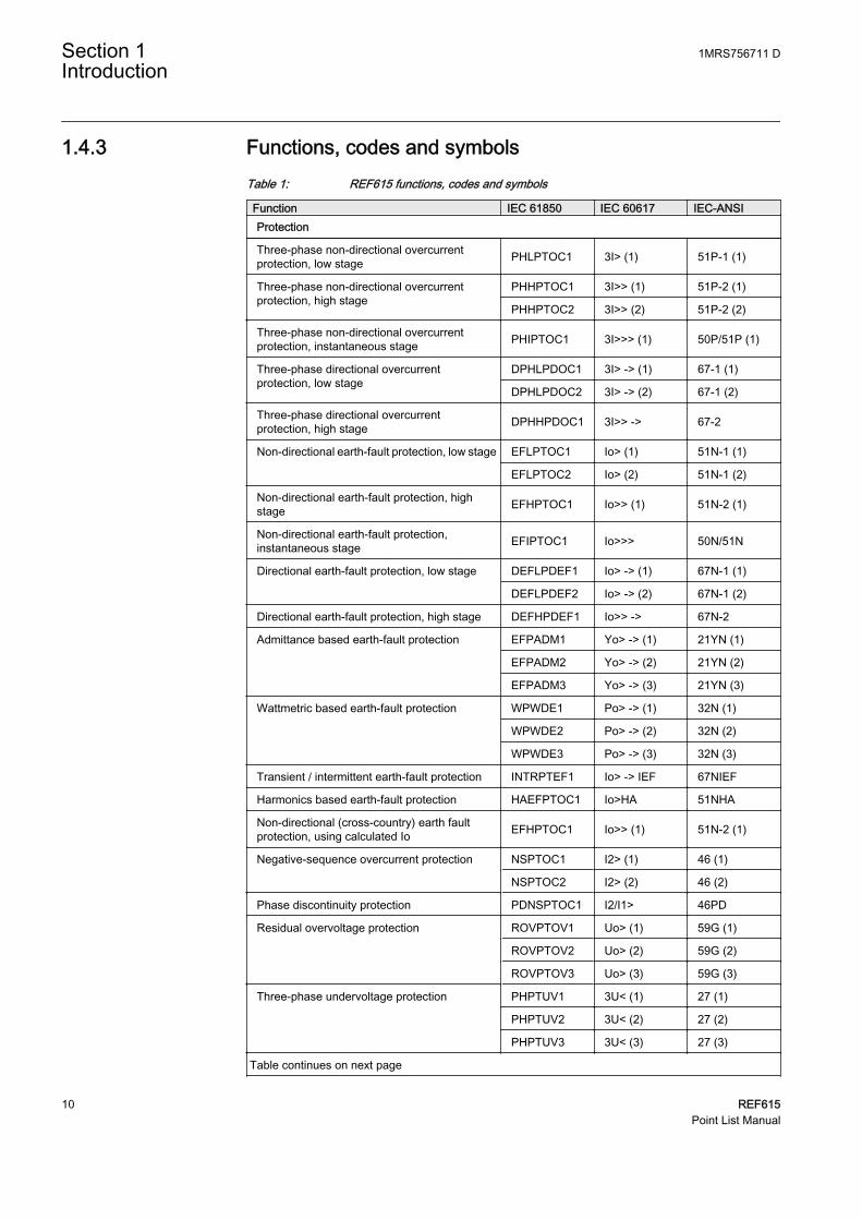
1.4.3 Functions, codes and symbolsTable 1: REF615 functions, codes and symbols
Function IEC 61850 IEC 60617 IEC-ANSIProtection
Three-phase non-directional overcurrentprotection, low stage PHLPTOC1 3I> (1) 51P-1 (1)
Three-phase non-directional overcurrentprotection, high stage
PHHPTOC1 3I>> (1) 51P-2 (1)
PHHPTOC2 3I>> (2) 51P-2 (2)
Three-phase non-directional overcurrentprotection, instantaneous stage PHIPTOC1 3I>>> (1) 50P/51P (1)
Three-phase directional overcurrentprotection, low stage
DPHLPDOC1 3I> -> (1) 67-1 (1)
DPHLPDOC2 3I> -> (2) 67-1 (2)
Three-phase directional overcurrentprotection, high stage DPHHPDOC1 3I>> -> 67-2
Non-directional earth-fault protection, low stage EFLPTOC1 Io> (1) 51N-1 (1)
EFLPTOC2 Io> (2) 51N-1 (2)
Non-directional earth-fault protection, highstage EFHPTOC1 Io>> (1) 51N-2 (1)
Non-directional earth-fault protection,instantaneous stage EFIPTOC1 Io>>> 50N/51N
Directional earth-fault protection, low stage DEFLPDEF1 Io> -> (1) 67N-1 (1)
DEFLPDEF2 Io> -> (2) 67N-1 (2)
Directional earth-fault protection, high stage DEFHPDEF1 Io>> -> 67N-2
Admittance based earth-fault protection EFPADM1 Yo> -> (1) 21YN (1)
EFPADM2 Yo> -> (2) 21YN (2)
EFPADM3 Yo> -> (3) 21YN (3)
Wattmetric based earth-fault protection WPWDE1 Po> -> (1) 32N (1)
WPWDE2 Po> -> (2) 32N (2)
WPWDE3 Po> -> (3) 32N (3)
Transient / intermittent earth-fault protection INTRPTEF1 Io> -> IEF 67NIEF
Harmonics based earth-fault protection HAEFPTOC1 Io>HA 51NHA
Non-directional (cross-country) earth faultprotection, using calculated Io EFHPTOC1 Io>> (1) 51N-2 (1)
Negative-sequence overcurrent protection NSPTOC1 I2> (1) 46 (1)
NSPTOC2 I2> (2) 46 (2)
Phase discontinuity protection PDNSPTOC1 I2/I1> 46PD
Residual overvoltage protection ROVPTOV1 Uo> (1) 59G (1)
ROVPTOV2 Uo> (2) 59G (2)
ROVPTOV3 Uo> (3) 59G (3)
Three-phase undervoltage protection PHPTUV1 3U< (1) 27 (1)
PHPTUV2 3U< (2) 27 (2)
PHPTUV3 3U< (3) 27 (3)
Table continues on next page
Section 1 1MRS756711 DIntroduction
10 REF615Point List Manual

Function IEC 61850 IEC 60617 IEC-ANSIThree-phase overvoltage protection PHPTOV1 3U> (1) 59 (1)
PHPTOV2 3U> (2) 59 (2)
PHPTOV3 3U> (3) 59 (3)
Positive-sequence undervoltage protection PSPTUV1 U1< (1) 47U+ (1)
Negative-sequence overvoltage protection NSPTOV1 U2> (1) 47O- (1)
Frequency protection FRPFRQ1 f>/f<,df/dt (1) 81 (1)
FRPFRQ2 f>/f<,df/dt (2) 81 (2)
FRPFRQ3 f>/f<,df/dt (3) 81 (3)
Three-phase thermal protection for feeders,cables and distribution transformers T1PTTR1 3Ith>F 49F
Circuit breaker failure protection CCBRBRF1 3I>/Io>BF 51BF/51NBF
Three-phase inrush detector INRPHAR1 3I2f> 68
Master trip TRPPTRC1 Master Trip (1) 94/86 (1)
TRPPTRC2 Master Trip (2) 94/86 (2)
Arc protection ARCSARC1 ARC (1) 50L/50NL (1)
ARCSARC2 ARC (2) 50L/50NL (2)
ARCSARC3 ARC (3) 50L/50NL (3)
Power quality
Current total demand distortion CMHAI1 PQM3I (1) PQM3I (1)
Voltage total harmonic distortion VMHAI1 PQM3U (1) PQM3V (1)
Voltage variation PHQVVR1 PQMU (1) PQMV (1)
Control
Circuit-breaker control CBXCBR1 I <-> O CB I <-> O CB
Disconnector control DCXSWI1 I <-> O DCC (1) I <-> O DCC (1)
DCXSWI2 I <-> O DCC (2) I <-> O DCC (2)
Earthing switch control ESXSWI1 I <-> O ESC I <-> O ESC
Disconnector position indication DCSXSWI1 I <-> O DC (1) I <-> O DC (1)
DCSXSWI2 I <-> O DC (2) I <-> O DC (2)
DCSXSWI3 I <-> O DC (3) I <-> O DC (3)
Earthing switch indication ESSXSWI1 I <-> O ES (1) I <-> O ES (1)
ESSXSWI2 I <-> O ES (2) I <-> O ES (2)
Auto-reclosing DARREC1 O -> I 79
Synchronism and energizing check SECRSYN1 SYNC 25
Condition monitoring
Circuit-breaker condition monitoring SSCBR1 CBCM CBCM
Trip circuit supervision TCSSCBR1 TCS (1) TCM (1)
TCSSCBR2 TCS (2) TCM (2)
Current circuit supervision CCRDIF1 MCS 3I MCS 3I
Fuse failure supervision SEQRFUF1 FUSEF 60
Measurement
Table continues on next page
1MRS756711 D Section 1Introduction
REF615 11Point List Manual

Function IEC 61850 IEC 60617 IEC-ANSIDisturbance recorder RDRE1 - -
Three-phase current measurement CMMXU1 3I 3I
Sequence current measurement CSMSQI1 I1, I2, I0 I1, I2, I0
Residual current measurement RESCMMXU1 Io In
Three-phase voltage measurement VMMXU1 3U 3U
Residual voltage measurement RESVMMXU1 Uo Vn
Sequence voltage measurement VSMSQI1 U1, U2, U0 U1, U2, U0
Three-phase power and energy measurement PEMMXU1 P, E P, E
Frequency measurement FMMXU1 f f
Section 1 1MRS756711 DIntroduction
12 REF615Point List Manual
Section 2 DNP3 data mappings
2.1 Overview
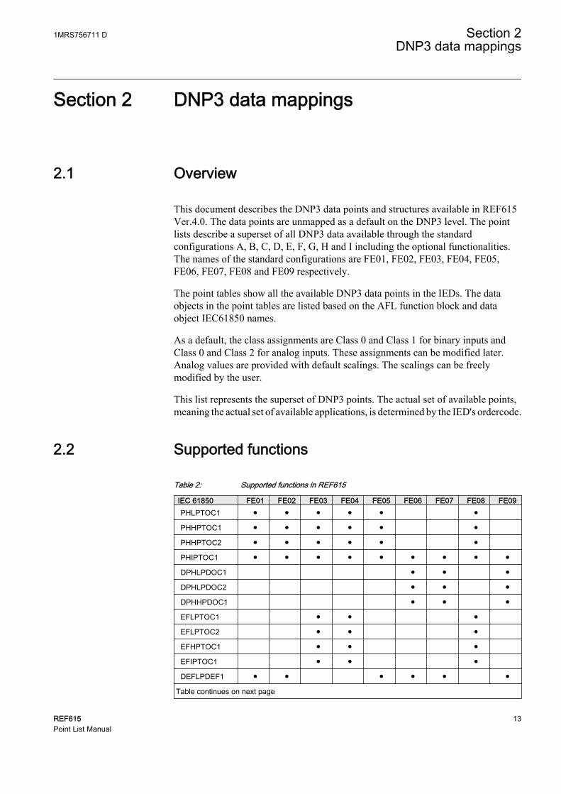
This document describes the DNP3 data points and structures available in REF615Ver.4.0. The data points are unmapped as a default on the DNP3 level. The pointlists describe a superset of all DNP3 data available through the standardconfigurations A, B, C, D, E, F, G, H and I including the optional functionalities.The names of the standard configurations are FE01, FE02, FE03, FE04, FE05,FE06, FE07, FE08 and FE09 respectively.
The point tables show all the available DNP3 data points in the IEDs. The dataobjects in the point tables are listed based on the AFL function block and dataobject IEC61850 names.
As a default, the class assignments are Class 0 and Class 1 for binary inputs andClass 0 and Class 2 for analog inputs. These assignments can be modified later.Analog values are provided with default scalings. The scalings can be freelymodified by the user.
This list represents the superset of DNP3 points. The actual set of available points,meaning the actual set of available applications, is determined by the IED's ordercode.
2.2 Supported functions
Table 2: Supported functions in REF615
IEC 61850 FE01 FE02 FE03 FE04 FE05 FE06 FE07 FE08 FE09PHLPTOC1 ● ● ● ● ● ●
PHHPTOC1 ● ● ● ● ● ●
PHHPTOC2 ● ● ● ● ● ●
PHIPTOC1 ● ● ● ● ● ● ● ● ●
DPHLPDOC1 ● ● ●
DPHLPDOC2 ● ● ●
DPHHPDOC1 ● ● ●
EFLPTOC1 ● ● ●
EFLPTOC2 ● ● ●
EFHPTOC1 ● ● ●
EFIPTOC1 ● ● ●
DEFLPDEF1 ● ● ● ● ● ●
Table continues on next page
1MRS756711 D Section 2DNP3 data mappings
REF615 13Point List Manual

IEC 61850 FE01 FE02 FE03 FE04 FE05 FE06 FE07 FE08 FE09DEFLPDEF2 ● ● ● ● ● ●
DEFHPDEF1 ● ● ● ● ● ●
EFPADM1 o o o o o o
EFPADM2 o o o o o o
EFPADM3 o o o o o o
WPWDE1 o o o o o o
WPWDE2 o o o o o o
WPWDE3 o o o o o o
INTRPTEF1 ● ● ● ● ●
HAEFPTOC1 o o o o
EFHPTOC1 ● ● ● ● ● ●
NSPTOC1 ● ● ● ● ● ● ● ● ●
NSPTOC2 ● ● ● ● ● ● ● ● ●
PDNSPTOC1 ● ● ● ● ● ● ● ● ●
ROVPTOV1 ● ● ● ● ● ● ●
ROVPTOV2 ● ● ● ● ● ● ●
ROVPTOV3 ● ● ● ● ● ● ●
PHPTUV1 ● ● ● ●
PHPTUV2 ● ● ● ●
PHPTUV3 ● ● ● ●
PHPTOV1 ● ● ● ●
PHPTOV2 ● ● ● ●
PHPTOV3 ● ● ● ●
PSPTUV1 ● ● ●
NSPTOV1 ● ● ●
FRPFRQ1 ● ●
FRPFRQ2 ● ●
FRPFRQ3 ● ●
T1PTTR1 ● ● ● ● ● ● ● ●
CCBRBRF1 ● ● ● ● ● ● ● ● ●
INRPHAR1 ● ● ● ● ● ● ● ● ●
TRPPTRC1 ● ● ● ● ● ● ● ● ●
TRPPTRC2 ● ● ● ● ● ● ● ● ●
ARCSARC1 o o o o o o o o o
ARCSARC2 o o o o o o o o o
ARCSARC3 o o o o o o o o o
CMHAI1 o
VMHAI1 o
PHQVVR1 o
Table continues on next page
Section 2 1MRS756711 DDNP3 data mappings
14 REF615Point List Manual

IEC 61850 FE01 FE02 FE03 FE04 FE05 FE06 FE07 FE08 FE09CBXCBR1 ● ● ● ● ● ● ● ● ●
DCXSWI1 ● ● ● ● ● ● ●
DCXSWI2 ● ● ● ● ● ● ●
ESXSWI1 ● ● ● ● ● ● ●
DCSXSWI1 ● ● ● ● ● ● ●
DCSXSWI2 ● ● ● ● ● ● ●
DCSXSWI3 ● ● ● ● ● ● ●
ESSXSWI1 ● ● ● ● ● ● ●
ESSXSWI2 ● ● ● ● ● ● ●
DARREC1 o o o o o o o o o
SECRSYN1 ● ●
SSCBR1 ● ● ● ● ● ● ●
TCSSCBR1 ● ● ● ● ● ● ● ● ●
TCSSCBR2 ● ● ● ● ● ● ● ● ●
CCRDIF1 ● ● ● ● ●
SEQRFUF1 ● ● ● ● ●
RDRE1 ● ● ● ● ● ● ● ● ●
CMMXU1 ● ● ● ● ● ● ● ● ●
CSMSQI1 ● ● ● ● ● ● ● ● ●
RESCMMXU1 ● ● ● ● ● ● ● ● ●
VMMXU1 ● ● ● ● ●
RESVMMXU1 ● ● ● ● ● ●
VSMSQI1 ● ● ● ● ●
PEMMXU1 ● ● ● ● ●
FMMXU1 ● ●
● = available in the device variant, o = optionally available in the device variant
2.3 Point list for REF615 Ver.4.0 FE01-09
2.3.1 Binary inputsTable 3: Explanations of the binary input table columns
Column name DescriptionIEC 61850name
Original IED data object identification. Described in the IEC 61850 format asLogical Device.Logical Node and thereafter .Data Object.Data Attribute. LogicalNode is the same as the application function block name.
SA name The signal may have a defined label that is visible for example in ACT.
Description Short description of the signal. See the application function block documentationfor more details.
Value Meaning of the input states.
1MRS756711 D Section 2DNP3 data mappings
REF615 15Point List Manual

2.3.1.1 LD0.ARCSARC1 Fault arc protection stage 1
Table 4: LD0.ARCSARC1 Fault arc protection stage 1
IEC 61850 name SA name Description ValuesLD0.ARCSARC11
.FADet.stVal ARC_FLT_DET Arc detected 1=Detected
LD0.ARCPTRC11
.Op.general OPERATE Operate 1=Operate
2.3.1.2 LD0.ARCSARC2 Fault arc protection stage 2
Table 5: LD0.ARCSARC2 Fault arc protection stage 2
IEC 61850 name SA name Description ValuesLD0.ARCSARC21
.FADet.stVal ARC_FLT_DET Arc detected 1=Detected
LD0.ARCPTRC21
.Op.general OPERATE Operate 1=Operate
2.3.1.3 LD0.ARCSARC3 Fault arc protection stage 3
Table 6: LD0.ARCSARC3 Fault arc protection stage 3
IEC 61850 name SA name Description ValuesLD0.ARCSARC31
.FADet.stVal ARC_FLT_DET Arc detected 1=Detected
LD0.ARCPTRC31
.Op.general OPERATE Operate 1=Operate
2.3.1.4 CTRL.Cxxxxx1 Circuit breaker (1) CB object and failure protection
Table 7: CTRL.Cxxxxx1 Circuit breaker (1) CB object and failure protection
IEC 61850 name SA name Description ValuesCTRL.CBCILO1
.EnaCls.stVal ENA_CLOSE Close enabled 1=Enabled
.EnaOpn.stVal ENA_OPEN Open enabled 1=Enabled
.ItlByPss.stVal ITL_BYPASS Interlocking bypass 1=Bypassed
CTRL.CBCSWI1
.Pos.stSeld SELECTED CB selected 1=Selected
CTRL.CBXCBR1
.BlkCls.stVal BLK_CLOSE Close blocked 1=Blocked
.BlkOpn.stVal BLK_OPEN Open blocked 1=Blocked
Table continues on next page
Section 2 1MRS756711 DDNP3 data mappings
16 REF615Point List Manual
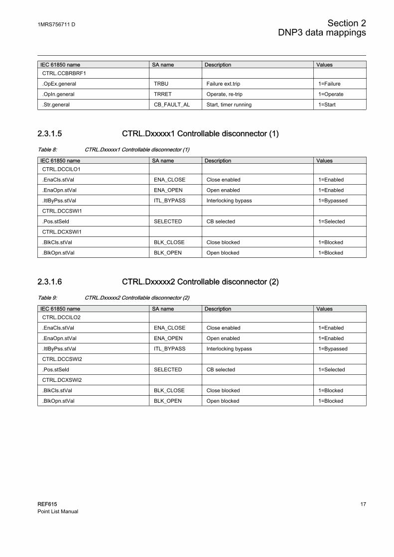
IEC 61850 name SA name Description ValuesCTRL.CCBRBRF1
.OpEx.general TRBU Failure ext.trip 1=Failure
.OpIn.general TRRET Operate, re-trip 1=Operate
.Str.general CB_FAULT_AL Start, timer running 1=Start
2.3.1.5 CTRL.Dxxxxx1 Controllable disconnector (1)
Table 8: CTRL.Dxxxxx1 Controllable disconnector (1)
IEC 61850 name SA name Description ValuesCTRL.DCCILO1
.EnaCls.stVal ENA_CLOSE Close enabled 1=Enabled
.EnaOpn.stVal ENA_OPEN Open enabled 1=Enabled
.ItlByPss.stVal ITL_BYPASS Interlocking bypass 1=Bypassed
CTRL.DCCSWI1
.Pos.stSeld SELECTED CB selected 1=Selected
CTRL.DCXSWI1
.BlkCls.stVal BLK_CLOSE Close blocked 1=Blocked
.BlkOpn.stVal BLK_OPEN Open blocked 1=Blocked
2.3.1.6 CTRL.Dxxxxx2 Controllable disconnector (2)
Table 9: CTRL.Dxxxxx2 Controllable disconnector (2)
IEC 61850 name SA name Description ValuesCTRL.DCCILO2
.EnaCls.stVal ENA_CLOSE Close enabled 1=Enabled
.EnaOpn.stVal ENA_OPEN Open enabled 1=Enabled
.ItlByPss.stVal ITL_BYPASS Interlocking bypass 1=Bypassed
CTRL.DCCSWI2
.Pos.stSeld SELECTED CB selected 1=Selected
CTRL.DCXSWI2
.BlkCls.stVal BLK_CLOSE Close blocked 1=Blocked
.BlkOpn.stVal BLK_OPEN Open blocked 1=Blocked
1MRS756711 D Section 2DNP3 data mappings
REF615 17Point List Manual

2.3.1.7 CTRL.Exxxxx1 Controllable earth switch (1)
Table 10: CTRL.Exxxxx1 Controllable earth switch (1)
IEC 61850 name SA name Description ValuesCTRL.ESCILO1
.EnaCls.stVal ENA_CLOSE Close enabled 1=Enabled
.EnaOpn.stVal ENA_OPEN Open enabled 1=Enabled
.ItlByPss.stVal ITL_BYPASS Interlocking bypass 1=Bypassed
CTRL.ESCSWI1
.Pos.stSeld SELECTED CB selected 1=Selected
CTRL.ESXSWI1
.BlkCls.stVal BLK_CLOSE Close blocked 1=Blocked
.BlkOpn.stVal BLK_OPEN Open blocked 1=Blocked
2.3.1.8 CTRL.CCRDIF1 Current circuit failure protection
Table 11: CTRL.CCRDIF1 Current circuit failure protection
IEC 61850 name SA name Description ValuesCTRL.CCRDIF1
.Alm.stVal FAIL Fail Alarm 1=Alarm
.Op.general ALARM Fail Operate 1=Operate
2.3.1.9 LD0.CMHAI1 Power quality - current total demand distortion
Table 12: LD0.CMHAI1 Power quality - current total demand distortion
IEC 61850 name SA name Description ValuesLD0.CMHAI1
.Alm.stVal ALARM Distortion alarm 10=Alarm
2.3.1.10 LD0.CMMXU1 Phase currents (1) limit supervision
Table 13: LD0.CMMXU1 Phase currents (1) limit supervision
IEC 61850 name SA name Description ValuesLD0.CMMXU1
.HiAlm.stVal HIGH_ALARM High alarm 1=Alarm
.HiWrn.stVal HIGH_WARN High warning 1=Warning
.LoAlm.stVal LOW_ALARM Low alarm 1=Alarm
.LoWrn.stVal LOW_WARN Low warning 1=Warning
Section 2 1MRS756711 DDNP3 data mappings
18 REF615Point List Manual

2.3.1.11 LD0.DARREC1 Autorecloser
Table 14: LD0.DARREC1 Autorecloser
IEC 61850 name SA name Description ValuesLD0.DARREC1
.PrgRec1.stVal INPRO_1 AR 1st reclose 1=In progress
.PrgRec2.stVal INPRO_2 AR 2nd reclose 1=In progress
.PrgRec3.stVal INPRO_3 AR 3rd reclose 1=In progress
.PrgRec4.stVal INPRO_4 AR 4th reclose 1=In progress
.PrgRec5.stVal INPRO_5 AR 5th reclose 1=In progress
.PrgRec.stVal INPRO AR in progress 1=In progress
.CBManCls.stVal MAN_CB_CL CB manually closed 1=CB closed
.LO.stVal LOCKED Lockout status 1=Lockout
.UnsRec.stVal UNSUC_RECL Reclose fail status 1=Failed
.InBlkThm.stVal - Thermal block (status) 1=Block
.RdyRec.stVal READY Ready reclose status 1=Ready
.ActRec.stVal ACTIVE Active reclose status 1=Active
.PrgDsr.stVal DISCR_INPRO Discrimination time in p. 1=In progress
.PrgCutOut.stVal CUTOUT_INPRO Cutout time in progress 1=In progress
.FrqOpAlm.stVal FRQ_OP_ALM Frequent operation alarm 1=Alarm
.RclTmStr.stVal - Reclaim time started 1=Started
.ProCrd.stVal - Protection coordination 1=In progress
.Op.general CLOSE_CB Operate (close XCBR) 1=Close CB
.OpOpn.general OPEN_CB Operate (open XCBR) 1=Open CB
.UnsCBCls.stVal UNSUC_CB CB closing failed 1=Failed
.WtMstr.stVal CMD_WAIT Master signal to follower 1=Signal
2.3.1.12 LD0.DEFHPDEF1 Directional earth-fault protection - high stage 1
Table 15: LD0.DEFHPDEF1 Directional earth-fault protection - high stage 1
IEC 61850 name SA name Description ValuesLD0.DEFHPTOC1 High stage (1)
.Op.general OPERATE -Operate 1=Operate
.Str.general START -Start 1=Start
1MRS756711 D Section 2DNP3 data mappings
REF615 19Point List Manual

2.3.1.13 LD0.DEFLPDEF1 Directional earth-fault protection - low stage 1
Table 16: LD0.DEFLPDEF1 Directional earth-fault protection - low stage 1
IEC 61850 name SA name Description ValuesLD0.DEFLPTOC1 Low stage (1)
.Op.general OPERATE -Operate 1=Operate
.Str.general START -Start 1=Start
2.3.1.14 LD0.DEFLPDEF2 Directional earth-fault protection - low stage 2
Table 17: LD0.DEFLPDEF2 Directional earth-fault protection - low stage 2
IEC 61850 name SA name Description ValuesLD0.DEFLPTOC2 Low stage (2)
.Op.general OPERATE -Operate 1=Operate
.Str.general START -Start 1=Start
2.3.1.15 LD0.DPHLPDOC1 Three-phase directional overcurrent protection -low stage (1)
Table 18: LD0.DPHLPDOC1 Three-phase directional overcurrent protection - low stage (1)
IEC 61850 name SA name Description ValuesLD0.DPHLPTOC1 Low stage (1)
.Op.general OPERATE -Operate 1=Operate
.Str.general START -Start 1=Start
2.3.1.16 LD0.DPHLPDOC2 Three-phase directional overcurrent protection -low stage (2)
Table 19: LD0.DPHLPDOC2 Three-phase directional overcurrent protection - low stage (2)
IEC 61850 name SA name Description ValuesLD0.DPHLPTOC2 Low stage (2)
.Op.general OPERATE -Operate 1=Operate
.Str.general START -Start 1=Start
Section 2 1MRS756711 DDNP3 data mappings
20 REF615Point List Manual

2.3.1.17 LD0.DPHHPDOC1 Three-phase directional overcurrent protection -high stage (1)
Table 20: LD0.DPHHPDOC1 Three-phase directional overcurrent protection - high stage (1)
IEC 61850 name SA name Description ValuesLD0.DPHHPTOC1 High stage (1)
.Op.general OPERATE -Operate 1=Operate
.Str.general START -Start 1=Start
2.3.1.18 LD0.EFHPTOC1 Non-directional earth-fault and sensitive earth-faultprotection - high stage 1
Table 21: LD0.EFHPTOC1 Non-directional earth-fault and sensitive earth-fault protection - high stage 1
IEC 61850 name SA name Description ValuesLD0.EFHPTOC1 High stage (1)
.Op.general OPERATE -Operate 1=Operate
.Str.general START -Start 1=Start
2.3.1.19 LD0.EFIPTOC1 Non-directional earth-fault and sensitive earth-faultprotection - instantaneous stage 1
Table 22: LD0.EFIPTOC1 Non-directional earth-fault and sensitive earth-fault protection - instantaneous stage 1
IEC 61850 name SA name Description ValuesLD0.EFIPTOC1 Instant. stage (1)
.Op.general OPERATE -Operate 1=Operate
.Str.general START -Start 1=Start
2.3.1.20 LD0.EFLPTOC1 Non-directional earth-fault and sensitive earth-faultprotection - low stage 1
Table 23: LD0.EFLPTOC1 Non-directional earth-fault and sensitive earth-fault protection - low stage 1
IEC 61850 name SA name Description ValuesLD0.EFLPTOC1 Low stage (1)
.Op.general OPERATE -Operate 1=Operate
.Str.general START -Start 1=Start
1MRS756711 D Section 2DNP3 data mappings
REF615 21Point List Manual

2.3.1.21 LD0.EFLPTOC2 Non-directional earth-fault and sensitive earth-faultprotection - low stage 2
Table 24: LD0.EFLPTOC2 Non-directional earth-fault and sensitive earth-fault protection - low stage 2
IEC 61850 name SA name Description ValuesLD0.EFLPTOC2 Low stage (2)
.Op.general OPERATE -Operate 1=Operate
.Str.general START -Start 1=Start
2.3.1.22 LD0.EFPADM1 Admittance-based earth-fault protection (1)
Table 25: LD0.EFPADM1 Admittance-based earth-fault protection (1)
IEC 61850 name SA name Description ValuesLD0.EFPADM1
.Str.general START Stage1 start 1=Start
.Op.general OPERATE Stage1 operate 1=Operate
2.3.1.23 LD0.EFPADM2 Admittance-based earth-fault protection (2)
Table 26: LD0.EFPADM2 Admittance-based earth-fault protection (2)
IEC 61850 name SA name Description ValuesLD0.EFPADM2
.Str.general START Stage2 start 1=Start
.Op.general OPERATE Stage2 operate 1=Operate
2.3.1.24 LD0.EFPADM3 Admittance-based earth-fault protection (3)
Table 27: LD0.EFPADM3 Admittance-based earth-fault protection (3)
IEC 61850 name SA name Description ValuesLD0.EFPADM3
.Str.general START Stage3 start 1=Start
.Op.general OPERATE Stage3 operate 1=Operate
2.3.1.25 LD0.FRPFRQ1 Frequency protection (1)
Table 28: LD0.FRPFRQ1 Frequency protection (1)
IEC 61850 name SA name Description ValuesLD0.FRPTRC1
.Str.general START Stage start 1=Start
LD0.FRPTOF1 Overfrequency
Table continues on next page
Section 2 1MRS756711 DDNP3 data mappings
22 REF615Point List Manual
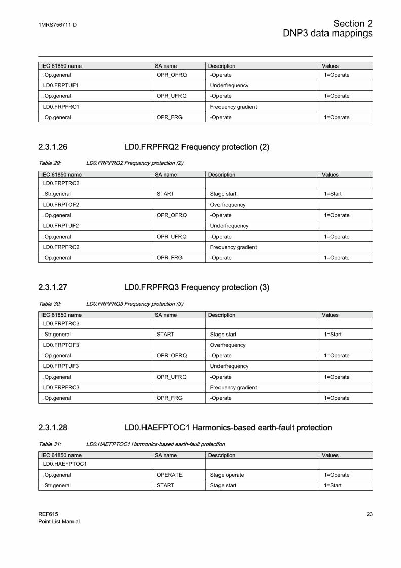
IEC 61850 name SA name Description Values.Op.general OPR_OFRQ -Operate 1=Operate
LD0.FRPTUF1 Underfrequency
.Op.general OPR_UFRQ -Operate 1=Operate
LD0.FRPFRC1 Frequency gradient
.Op.general OPR_FRG -Operate 1=Operate
2.3.1.26 LD0.FRPFRQ2 Frequency protection (2)
Table 29: LD0.FRPFRQ2 Frequency protection (2)
IEC 61850 name SA name Description ValuesLD0.FRPTRC2
.Str.general START Stage start 1=Start
LD0.FRPTOF2 Overfrequency
.Op.general OPR_OFRQ -Operate 1=Operate
LD0.FRPTUF2 Underfrequency
.Op.general OPR_UFRQ -Operate 1=Operate
LD0.FRPFRC2 Frequency gradient
.Op.general OPR_FRG -Operate 1=Operate
2.3.1.27 LD0.FRPFRQ3 Frequency protection (3)
Table 30: LD0.FRPFRQ3 Frequency protection (3)
IEC 61850 name SA name Description ValuesLD0.FRPTRC3
.Str.general START Stage start 1=Start
LD0.FRPTOF3 Overfrequency
.Op.general OPR_OFRQ -Operate 1=Operate
LD0.FRPTUF3 Underfrequency
.Op.general OPR_UFRQ -Operate 1=Operate
LD0.FRPFRC3 Frequency gradient
.Op.general OPR_FRG -Operate 1=Operate
2.3.1.28 LD0.HAEFPTOC1 Harmonics-based earth-fault protection
Table 31: LD0.HAEFPTOC1 Harmonics-based earth-fault protection
IEC 61850 name SA name Description ValuesLD0.HAEFPTOC1
.Op.general OPERATE Stage operate 1=Operate
.Str.general START Stage start 1=Start
1MRS756711 D Section 2DNP3 data mappings
REF615 23Point List Manual
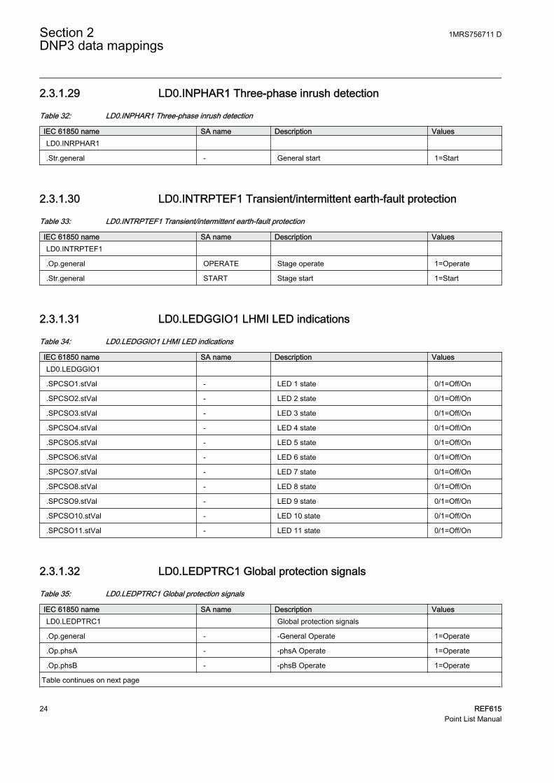
2.3.1.29 LD0.INPHAR1 Three-phase inrush detection
Table 32: LD0.INPHAR1 Three-phase inrush detection
IEC 61850 name SA name Description ValuesLD0.INRPHAR1
.Str.general - General start 1=Start
2.3.1.30 LD0.INTRPTEF1 Transient/intermittent earth-fault protection
Table 33: LD0.INTRPTEF1 Transient/intermittent earth-fault protection
IEC 61850 name SA name Description ValuesLD0.INTRPTEF1
.Op.general OPERATE Stage operate 1=Operate
.Str.general START Stage start 1=Start
2.3.1.31 LD0.LEDGGIO1 LHMI LED indications
Table 34: LD0.LEDGGIO1 LHMI LED indications
IEC 61850 name SA name Description ValuesLD0.LEDGGIO1
.SPCSO1.stVal - LED 1 state 0/1=Off/On
.SPCSO2.stVal - LED 2 state 0/1=Off/On
.SPCSO3.stVal - LED 3 state 0/1=Off/On
.SPCSO4.stVal - LED 4 state 0/1=Off/On
.SPCSO5.stVal - LED 5 state 0/1=Off/On
.SPCSO6.stVal - LED 6 state 0/1=Off/On
.SPCSO7.stVal - LED 7 state 0/1=Off/On
.SPCSO8.stVal - LED 8 state 0/1=Off/On
.SPCSO9.stVal - LED 9 state 0/1=Off/On
.SPCSO10.stVal - LED 10 state 0/1=Off/On
.SPCSO11.stVal - LED 11 state 0/1=Off/On
2.3.1.32 LD0.LEDPTRC1 Global protection signals
Table 35: LD0.LEDPTRC1 Global protection signals
IEC 61850 name SA name Description ValuesLD0.LEDPTRC1 Global protection signals
.Op.general - -General Operate 1=Operate
.Op.phsA - -phsA Operate 1=Operate
.Op.phsB - -phsB Operate 1=Operate
Table continues on next page
Section 2 1MRS756711 DDNP3 data mappings
24 REF615Point List Manual
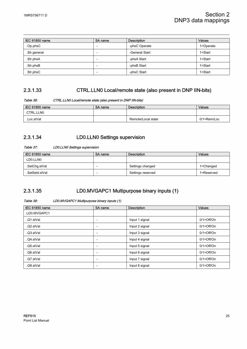
IEC 61850 name SA name Description Values.Op.phsC - -phsC Operate 1=Operate
.Str.general - -General Start 1=Start
.Str.phsA - -phsA Start 1=Start
.Str.phsB - -phsB Start 1=Start
.Str.phsC - -phsC Start 1=Start
2.3.1.33 CTRL.LLN0 Local/remote state (also present in DNP IIN-bits)
Table 36: CTRL.LLN0 Local/remote state (also present in DNP IIN-bits)
IEC 61850 name SA name Description ValuesCTRL.LLN0
.Loc.stVal Remote/Local state 0/1=Rem/Loc
2.3.1.34 LD0.LLN0 Settings supervision
Table 37: LD0.LLN0 Settings supervision
IEC 61850 name SA name Description ValuesLD0.LLN0
.SetChg.stVal - Settings changed 1=Changed
.SetSeld.stVal - Settings reserved 1=Reserved
2.3.1.35 LD0.MVGAPC1 Multipurpose binary inputs (1)
Table 38: LD0.MVGAPC1 Multipurpose binary inputs (1)
IEC 61850 name SA name Description ValuesLD0.MVGAPC1
.Q1.stVal - Input 1 signal 0/1=Off/On
.Q2.stVal - Input 2 signal 0/1=Off/On
.Q3.stVal - Input 3 signal 0/1=Off/On
.Q4.stVal - Input 4 signal 0/1=Off/On
.Q5.stVal - Input 5 signal 0/1=Off/On
.Q6.stVal - Input 6 signal 0/1=Off/On
.Q7.stVal - Input 7 signal 0/1=Off/On
.Q8.stVal - Input 8 signal 0/1=Off/On
1MRS756711 D Section 2DNP3 data mappings
REF615 25Point List Manual

2.3.1.36 LD0.MVGAPC2 Multipurpose binary inputs (2)
Table 39: LD0.MVGAPC2 Multipurpose binary inputs (2)
IEC 61850 name SA name Description ValuesLD0.MVGAPC2
.Q1.stVal - Input 1 signal 0/1=Off/On
.Q2.stVal - Input 2 signal 0/1=Off/On
.Q3.stVal - Input 3 signal 0/1=Off/On
.Q4.stVal - Input 4 signal 0/1=Off/On
.Q5.stVal - Input 5 signal 0/1=Off/On
.Q6.stVal - Input 6 signal 0/1=Off/On
.Q7.stVal - Input 7 signal 0/1=Off/On
.Q8.stVal - Input 8 signal 0/1=Off/On
2.3.1.37 LD0.NSPTOC1 Negative-sequence overcurrent protection (1)
Table 40: LD0.NSPTOC1 Negative-sequence overcurrent protection (1)
IEC 61850 name SA name Description ValuesLD0.NSPTOC1
.Op.general OPERATE Stage operate 1=Operate
.Str.general START Stage start 1=Start
2.3.1.38 LD0.NSPTOC2 Negative-sequence overcurrent protection (2)
Table 41: LD0.NSPTOC2 Negative-sequence overcurrent protection (2)
IEC 61850 name SA name Description ValuesLD0.NSPTOC2
.Op.general OPERATE Stage operate 1=Operate
.Str.general START Stage start 1=Start
2.3.1.39 LD0.NSPTOV1 Negative-sequence overvoltage protection - stage 1
Table 42: LD0.NSPTOV1 Negative-sequence overvoltage protection - stage 1
IEC 61850 name SA name Description ValuesLD0.NSPTOV1
.Op.general OPERATE Stage operate 1=Operate
.Str.general START Stage start 1=Start
Section 2 1MRS756711 DDNP3 data mappings
26 REF615Point List Manual

2.3.1.40 LD0.PDNSPTOC1 Phase discontinuity protection
Table 43: LD0.PDNSPTOC1 Phase discontinuity protection
IEC 61850 name SA name Description ValuesLD0.PDNSPTOC1
.Op.general OPERATE Stage operate 1=Operate
.Str.general START Stage start 1=Start
2.3.1.41 LD0.PHHPTOC1 Phase overcurrent protection - high stage 1
Table 44: LD0.PHHPTOC1 Phase overcurrent protection - high stage 1
IEC 61850 name SA name Description ValuesLD0.PHHPTOC1
.Op.general OPERATE Stage operate 1=Operate
.Str.general START Stage start 1=Start
2.3.1.42 LD0.PHHPTOC2 Phase overcurrent protection - high stage 2
Table 45: LD0.PHHPTOC2 Phase overcurrent protection - high stage 2
IEC 61850 name SA name Description ValuesLD0.PHHPTOC2
.Op.general OPERATE Stage operate 1=Operate
.Str.general START Stage start 1=Start
2.3.1.43 LD0.PHIPTOC1 Phase overcurrent protection - instantaneous stage 1
Table 46: LD0.PHIPTOC1 Phase overcurrent protection - instantaneous stage 1
IEC 61850 name SA name Description ValuesLD0.PHIPTOC1
.Op.general OPERATE Stage operate 1=Operate
.Str.general START Stage start 1=Start
2.3.1.44 LD0.PHLPTOC1 Phase overcurrent protection - low stage 1
Table 47: LD0.PHLPTOC1 Phase overcurrent protection - low stage 1
IEC 61850 name SA name Description ValuesLD0.PHLPTOC1
.Op.general OPERATE Stage operate 1=Operate
.Str.general START Stage start 1=Start
1MRS756711 D Section 2DNP3 data mappings
REF615 27Point List Manual

2.3.1.45 LD0.PHPTOV1 Phase overvoltage protection - stage 1
Table 48: LD0.PHPTOV1 Phase overvoltage protection - stage 1
IEC 61850 name SA name Description ValuesLD0.PHPTOV1
.Op.general OPERATE Stage operate 1=Operate
.Str.general START Stage start 1=Start
2.3.1.46 LD0.PHPTOV2 Phase overvoltage protection - stage 2
Table 49: LD0.PHPTOV2 Phase overvoltage protection - stage 2
IEC 61850 name SA name Description ValuesLD0.PHPTOV2
.Op.general OPERATE Stage operate 1=Operate
.Str.general START Stage start 1=Start
2.3.1.47 LD0.PHPTOV3 Phase overvoltage protection - stage 3
Table 50: LD0.PHPTOV3 Phase overvoltage protection - stage 3
IEC 61850 name SA name Description ValuesLD0.PHPTOV3
.Op.general OPERATE Stage operate 1=Operate
.Str.general START Stage start 1=Start
2.3.1.48 LD0.PHPTUV1 Phase undervoltage protection - stage 1
Table 51: LD0.PHPTUV1 Phase undervoltage protection - stage 1
IEC 61850 name SA name Description ValuesLD0.PHPTUV1
.Op.general OPERATE Stage operate 1=Operate
.Str.general START Stage start 1=Start
2.3.1.49 LD0.PHPTUV2 Phase undervoltage protection - stage 2
Table 52: LD0.PHPTUV2 Phase undervoltage protection - stage 2
IEC 61850 name SA name Description ValuesLD0.PHPTUV2
.Op.general OPERATE Stage operate 1=Operate
.Str.general START Stage start 1=Start
Section 2 1MRS756711 DDNP3 data mappings
28 REF615Point List Manual

2.3.1.50 LD0.PHPTUV3 Phase undervoltage protection - stage 3
Table 53: LD0.PHPTUV3 Phase undervoltage protection - stage 3
IEC 61850 name SA name Description ValuesLD0.PHPTUV3
.Op.general OPERATE Stage operate 1=Operate
.Str.general START Stage start 1=Start
2.3.1.51 LD0.PSPTUV1 Positive-sequence undervoltage protection - stage 1
Table 54: LD0.PSPTUV1 Positive-sequence undervoltage protection - stage 1
IEC 61850 name SA name Description ValuesLD0.PSPTUV1
.Op.general OPERATE Stage operate 1=Operate
.Str.general START Stage start 1=Start
2.3.1.52 LD0.PH1QVVR1 PQ - Voltage variation signals
Table 55: LD0.PH1QVVR1 PQ - Voltage variation signals
IEC 61850 name SA name Description ValuesLD0.PH1QVVR1
.VarStrGen.stVal - Variation event detected 1=Detected
.VarEnd.stVal - Variation event ended 1=Ended
.SwlOp.stVal - Swell event detected 1=Detected
.DipOp.stVal - Dip event detected 1=Detected
.IntrOp.stVal - Interruption event detected 1=Detected
2.3.1.53 DR.RDRE1 Disturbance recorder
Table 56: DR.RDRE1 Disturbance recorder
IEC 61850 name SA name Description ValuesDR.RDRE1
.RcdMade.stVal DR recording made 1=Made
2.3.1.54 LD0.RESCMMXU1 Residual current limit supervision
Table 57: LD0.RESCMMXU1 Residual current limit supervision
IEC 61850 name SA name Description ValuesLD0.RESCMMXU1
.HiAlm.stVal HIGH_ALARM High alarm 1=Alarm
.HiWrn.stVal HIGH_WARN High warning 1=Warning
1MRS756711 D Section 2DNP3 data mappings
REF615 29Point List Manual

2.3.1.55 LD0.RESVMMXU1 Residual voltage limit supervision
Table 58: LD0.RESVMMXU1 Residual voltage limit supervision
IEC 61850 name SA name Description ValuesLD0.RESVMMXU1
.HiAlm.stVal HIGH_ALARM High alarm 1=Alarm
.HiWrn.stVal HIGH_WARN High warning 1=Warning
2.3.1.56 LD0.ROVPTOV1 Residual overvoltage protection (1)
Table 59: LD0.ROVPTOV1 Residual overvoltage protection (1)
IEC 61850 name SA name Description ValuesLD0.ROVPTOV1
.Op.general OPERATE Stage 1 operate 1=Operate
.Str.general START Stage 1 start 1=Start
2.3.1.57 LD0.ROVPTOV2 Residual overvoltage protection (2)
Table 60: LD0.ROVPTOV2 Residual overvoltage protection (2)
IEC 61850 name SA name Description ValuesLD0.ROVPTOV2
.Op.general OPERATE Stage 2 operate 1=Operate
.Str.general START Stage 2 start 1=Start
2.3.1.58 LD0.ROVPTOV3 Residual overvoltage protection (3)
Table 61: LD0.ROVPTOV3 Residual overvoltage protection (3)
IEC 61850 name SA name Description ValuesLD0.ROVPTOV3
.Op.general OPERATE Stage 3 operate 1=Operate
.Str.general START Stage 3 start 1=Start
2.3.1.59 LD0.SECRSYN1 Synchrocheck
Table 62: LD0.SECRSYN1 Synchrocheck
IEC 61850 name SA name Description ValuesLD0.SECRSYN1
.SynPrg.stVal SYNC_INPRO Synch in progress 1=In progress
.FailCmd.stVal CMD_FAIL_AL CB close request failed 1=Failed
.FailSyn.stVal CL_FAIL_AL CB close command failed 1=Failed
Section 2 1MRS756711 DDNP3 data mappings
30 REF615Point List Manual
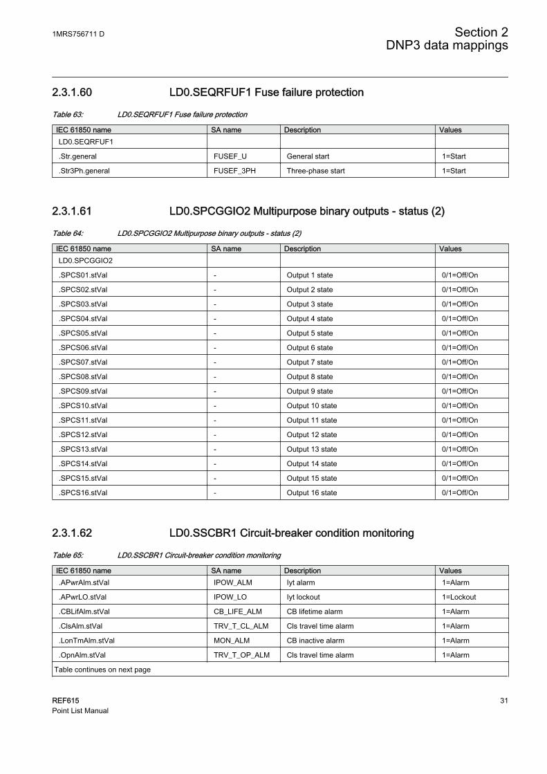
2.3.1.60 LD0.SEQRFUF1 Fuse failure protection
Table 63: LD0.SEQRFUF1 Fuse failure protection
IEC 61850 name SA name Description ValuesLD0.SEQRFUF1
.Str.general FUSEF_U General start 1=Start
.Str3Ph.general FUSEF_3PH Three-phase start 1=Start
2.3.1.61 LD0.SPCGGIO2 Multipurpose binary outputs - status (2)
Table 64: LD0.SPCGGIO2 Multipurpose binary outputs - status (2)
IEC 61850 name SA name Description ValuesLD0.SPCGGIO2
.SPCS01.stVal - Output 1 state 0/1=Off/On
.SPCS02.stVal - Output 2 state 0/1=Off/On
.SPCS03.stVal - Output 3 state 0/1=Off/On
.SPCS04.stVal - Output 4 state 0/1=Off/On
.SPCS05.stVal - Output 5 state 0/1=Off/On
.SPCS06.stVal - Output 6 state 0/1=Off/On
.SPCS07.stVal - Output 7 state 0/1=Off/On
.SPCS08.stVal - Output 8 state 0/1=Off/On
.SPCS09.stVal - Output 9 state 0/1=Off/On
.SPCS10.stVal - Output 10 state 0/1=Off/On
.SPCS11.stVal - Output 11 state 0/1=Off/On
.SPCS12.stVal - Output 12 state 0/1=Off/On
.SPCS13.stVal - Output 13 state 0/1=Off/On
.SPCS14.stVal - Output 14 state 0/1=Off/On
.SPCS15.stVal - Output 15 state 0/1=Off/On
.SPCS16.stVal - Output 16 state 0/1=Off/On
2.3.1.62 LD0.SSCBR1 Circuit-breaker condition monitoring
Table 65: LD0.SSCBR1 Circuit-breaker condition monitoring
IEC 61850 name SA name Description Values.APwrAlm.stVal IPOW_ALM Iyt alarm 1=Alarm
.APwrLO.stVal IPOW_LO Iyt lockout 1=Lockout
.CBLifAlm.stVal CB_LIFE_ALM CB lifetime alarm 1=Alarm
.ClsAlm.stVal TRV_T_CL_ALM Cls travel time alarm 1=Alarm
.LonTmAlm.stVal MON_ALM CB inactive alarm 1=Alarm
.OpnAlm.stVal TRV_T_OP_ALM Cls travel time alarm 1=Alarm
Table continues on next page
1MRS756711 D Section 2DNP3 data mappings
REF615 31Point List Manual

IEC 61850 name SA name Description Values.OpNumAlm.stVal OPR_ALM CB operations alarm 1=Alarm
.OpNumLO.stVal OPR_LO CB operations lockout 1=Lockout
.PresAlm.stVal PRES_ALM Low pressure alarm 1=Alarm
.PresLO.stVal PRES_LO Low pressure lockout 1=Lockout
.SprChaAlm.stVal SPR_CHR_ALM Spring charge time alarm 1=Alarm
2.3.1.63 LD0.T1PTTR1 Thermal protection (1)
Table 66: LD0.T1PTTR1 Thermal protection (1)
IEC 61850 name SA name Description ValuesLD0.T1PTTR1
.AlmThm.general ALARM Thermal alarm 1=Alarm
.Op.general OPERATE General operate 1=Operate
.Str.general START General start 1=Start
2.3.1.64 LD0.TCSSCBR1 Trip circuit supervision (1)
Table 67: LD0.TCSSCBR1 Trip circuit supervision (1)
IEC 61850 name SA name Description ValuesLD0.TCSSCBR1
.CirAlm.stVal ALARM Supervision alarm 1=Alarm
2.3.1.65 LD0.TCSSCBR2 Trip circuit supervision (2)
Table 68: LD0.TCSSCBR2 Trip circuit supervision (2)
IEC 61850 name SA name Description ValuesLD0.TCSSCBR2
.CirAlm.stVal ALARM Supervision alarm 1=Alarm
2.3.1.66 LD0.TRPPTRC1 Global conditioning (1)
Table 69: LD0.TRPPTRC1 Global conditioning (1)
IEC 61850 name SA name Description ValuesLD0.TRPPTRC1
.Op.general - Operate input signal 1=Operate
.Tr.general - Trip output signal 1=Trip
Section 2 1MRS756711 DDNP3 data mappings
32 REF615Point List Manual

2.3.1.67 LD0.TRPPTRC2 Global conditioning (2)
Table 70: LD0.TRPPTRC2 Global conditioning (2)
IEC 61850 name SA name Description Values.Op.general - Operate input signal 1=Operate
.Tr.general - Trip output signal 1=Trip
2.3.1.68 LD0.VMHAI1 PQ - Voltage total harmonic distortion
Table 71: LD0.VMHAI1 PQ - Voltage total harmonic distortion
IEC 61850 name SA name Description ValuesLD0.VMHAI1
.Alm.stVal - Distortion alarm 1=Alarm
2.3.1.69 LD0.VMMXU1 Three-phase voltage limit supervision
Table 72: LD0.VMMXU1 Three-phase voltage limit supervision
IEC 61850 name SA name Description ValuesLD0.VMMXU1
.HiAlm.stVal HIGH_ALARM High alarm 1=Alarm
.HiWrn.stVal HIGH_WARN High warning 1=Warning
.LoAlm.stVal LOW_ALARM Low alarm 1=Alarm
.LoWrn.stVal LOW_WARN Low warning 1=Warning
2.3.1.70 LD0.WPWDE1 Wattmetric-based earth-fault protection (1)
Table 73: LD0.WPWDE1 Wattmetric-based earth-fault protection (1)
IEC 61850 name SA name Description ValuesLD0.WPDSE1
.Str.general START Stage 1 start 1=Start
.Op.general OPERATE Stage 1 operate 1=Operate
2.3.1.71 LD0.WPWDE2 Wattmetric-based earth-fault protection (2)
Table 74: LD0.WPWDE2 Wattmetric-based earth-fault protection (2)
IEC 61850 name SA name Description ValuesLD0.WPDSE2
.Str.general START Stage 2 start 1=Start
.Op.general OPERATE Stage 2 operate 1=Operate
1MRS756711 D Section 2DNP3 data mappings
REF615 33Point List Manual

2.3.1.72 LD0.WPWDE3 Wattmetric-based earth-fault protection (3)
Table 75: LD0.WPWDE3 Wattmetric-based earth-fault protection (3)
IEC 61850 name SA name Description ValuesLD0.WPDSE3
.Str.general START Stage 3 start 1=Start
.Op.general OPERATE Stage 3 operate 1=Operate
2.3.1.73 LD0.XAGGIO130 Physical I/O
Table 76: LD0.XAGGIO130 Physical I/O
IEC 61850 name SA name Description ValuesLD0.XAGGIO130
.Ind1.stVal - X130-Input 1 1/0=ON/OFF
.Ind2.stVal - X130-Input 2 1/0=ON/OFF
.Ind3.stVal - X130-Input 3 1/0=ON/OFF
.Ind4.stVal - X130-Input 4 1/0=ON/OFF
2.3.1.74 LD0.XGGIO100 Physical I/O
Table 77: LD0.XGGIO100 Physical I/O
IEC 61850 name SA name Description ValuesLD0.XGGIO100
.SPCSO1.stVal - X100-Output 1 1/0=ON/OFF
.SPCSO2.stVal - X100-Output 2 1/0=ON/OFF
.SPCSO3.stVal - X100-Output 3 1/0=ON/OFF
.SPCSO4.stVal - X100-Output 4 1/0=ON/OFF
.SPCSO5.stVal - X100-Output 5 1/0=ON/OFF
.SPCSO6.stVal - X100-Output 6 1/0=ON/OFF
2.3.1.75 LD0.XGGIO110 Physical I/O
Table 78: LD0.XGGIO110 Physical I/O
IEC 61850 name SA name Description ValuesLD0.XGGIO110
.Ind1.stVal - X110-Input 1 1/0=ON/OFF
.Ind2.stVal - X110-Input 2 1/0=ON/OFF
.Ind3.stVal - X110-Input 3 1/0=ON/OFF
.Ind4.stVal - X110-Input 4 1/0=ON/OFF
.Ind5.stVal - X110-Input 5 1/0=ON/OFF
Table continues on next page
Section 2 1MRS756711 DDNP3 data mappings
34 REF615Point List Manual

IEC 61850 name SA name Description Values.Ind6.stVal - X110-Input 6 1/0=ON/OFF
.Ind7.stVal - X110-Input 7 1/0=ON/OFF
.Ind8.stVal - X110-Input 8 1/0=ON/OFF
.SPCSO1.stVal - X110-Output 1 1/0=ON/OFF
.SPCSO2.stVal - X110-Output 2 1/0=ON/OFF
.SPCSO3.stVal - X110-Output 3 1/0=ON/OFF
.SPCSO4.stVal - X110-Output 4 1/0=ON/OFF
2.3.1.76 LD0.XGGIO120 Physical I/O
Table 79: LD0.XGGIO120 Physical I/O
IEC 61850 name SA name Description ValuesLD0.XGGIO120
.Ind1.stVal - X120-Input 1 1/0=ON/OFF
.Ind2.stVal - X120-Input 2 1/0=ON/OFF
.Ind3.stVal - X120-Input 3 1/0=ON/OFF
.Ind4.stVal - X120-Input 4 1/0=ON/OFF
2.3.1.77 LD0.XGGIO130 Physical I/O
Table 80: LD0.XGGIO130 Physical I/O
IEC 61850 name SA name Description ValuesLD0.XGGIO130
.Ind1.stVal - X130-Input 1 1/0=ON/OFF
.Ind2.stVal - X130-Input 2 1/0=ON/OFF
.Ind3.stVal - X130-Input 3 1/0=ON/OFF
.Ind4.stVal - X130-Input 4 1/0=ON/OFF
.Ind5.stVal - X130-Input 5 1/0=ON/OFF
.Ind6.stVal - X130-Input 6 1/0=ON/OFF
.SPCSO1.stVal - X130-Output 1 1/0=ON/OFF
.SPCSO2.stVal - X130-Output 2 1/0=ON/OFF
.SPCSO3.stVal - X130-Output 3 1/0=ON/OFF
1MRS756711 D Section 2DNP3 data mappings
REF615 35Point List Manual
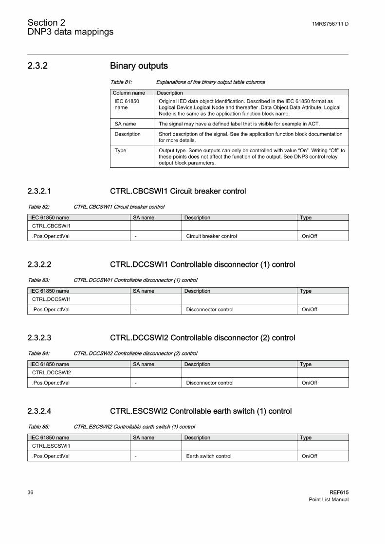
2.3.2 Binary outputsTable 81: Explanations of the binary output table columns
Column name DescriptionIEC 61850name
Original IED data object identification. Described in the IEC 61850 format asLogical Device.Logical Node and thereafter .Data Object.Data Attribute. LogicalNode is the same as the application function block name.
SA name The signal may have a defined label that is visible for example in ACT.
Description Short description of the signal. See the application function block documentationfor more details.
Type Output type. Some outputs can only be controlled with value “On”. Writing “Off” tothese points does not affect the function of the output. See DNP3 control relayoutput block parameters.
2.3.2.1 CTRL.CBCSWI1 Circuit breaker control
Table 82: CTRL.CBCSWI1 Circuit breaker control
IEC 61850 name SA name Description TypeCTRL.CBCSWI1
.Pos.Oper.ctlVal - Circuit breaker control On/Off
2.3.2.2 CTRL.DCCSWI1 Controllable disconnector (1) control
Table 83: CTRL.DCCSWI1 Controllable disconnector (1) control
IEC 61850 name SA name Description TypeCTRL.DCCSWI1
.Pos.Oper.ctlVal - Disconnector control On/Off
2.3.2.3 CTRL.DCCSWI2 Controllable disconnector (2) control
Table 84: CTRL.DCCSWI2 Controllable disconnector (2) control
IEC 61850 name SA name Description TypeCTRL.DCCSWI2
.Pos.Oper.ctlVal - Disconnector control On/Off
2.3.2.4 CTRL.ESCSWI2 Controllable earth switch (1) control
Table 85: CTRL.ESCSWI2 Controllable earth switch (1) control
IEC 61850 name SA name Description TypeCTRL.ESCSWI1
.Pos.Oper.ctlVal - Earth switch control On/Off
Section 2 1MRS756711 DDNP3 data mappings
36 REF615Point List Manual

2.3.2.5 LD0.DARREC1 Autoreclosing reset signals
Table 86: LD0.DARREC1 Autoreclosing reset signals
IEC 61850 name SA name Description TypeLD0.DARREC1
.RsCnt.Oper.ctlVal - AR reset all counters On
.RsRec.Oper.ctlVal - AR reset On
2.3.2.6 LD0.DNPGGIO1 Parameter setting group control
Table 87: LD0.DNPGGIO1 Parameter setting group control
IEC 61850 name SA name Description TypeLD0.DNPGGIO1
.ActSG1.ctlVal - Setting group 1 On
.ActSG2.ctlVal - Setting group 2 On
.ActSG3.ctlVal - Setting group 3 On
.ActSG4.ctlVal - Setting group 4 On
.ActSG5.ctlVal - Setting group 5 On
.ActSG6.ctlVal - Setting group 6 On
2.3.2.7 LD0.LLN0/LPHD1 Reset indications and LEDs, reset device
Table 88: LD0.LLN0/LPHD1 Reset indications and LEDs, reset device
IEC 61850 name SA name Description TypeLD0.LLN0
.LEDRs1.Oper.ctlVal - Reset indications and LEDs On
.LEDRs2.Oper.ctlVal - Reset alarm LEDs On
LD0.LPHD1
.RsDev.Oper.ctlVal - Reset device On
2.3.2.8 LD0.PEMMXU1 Reset accumulated energy values
Table 89: LD0.PEMMXU1 Reset accumulated energy values
IEC 61850 name SA name Description TypeLD0.PEMMXU1
.SupDmdRs.Oper.ctlVal RSTACM Reset accum. energy On
1MRS756711 D Section 2DNP3 data mappings
REF615 37Point List Manual
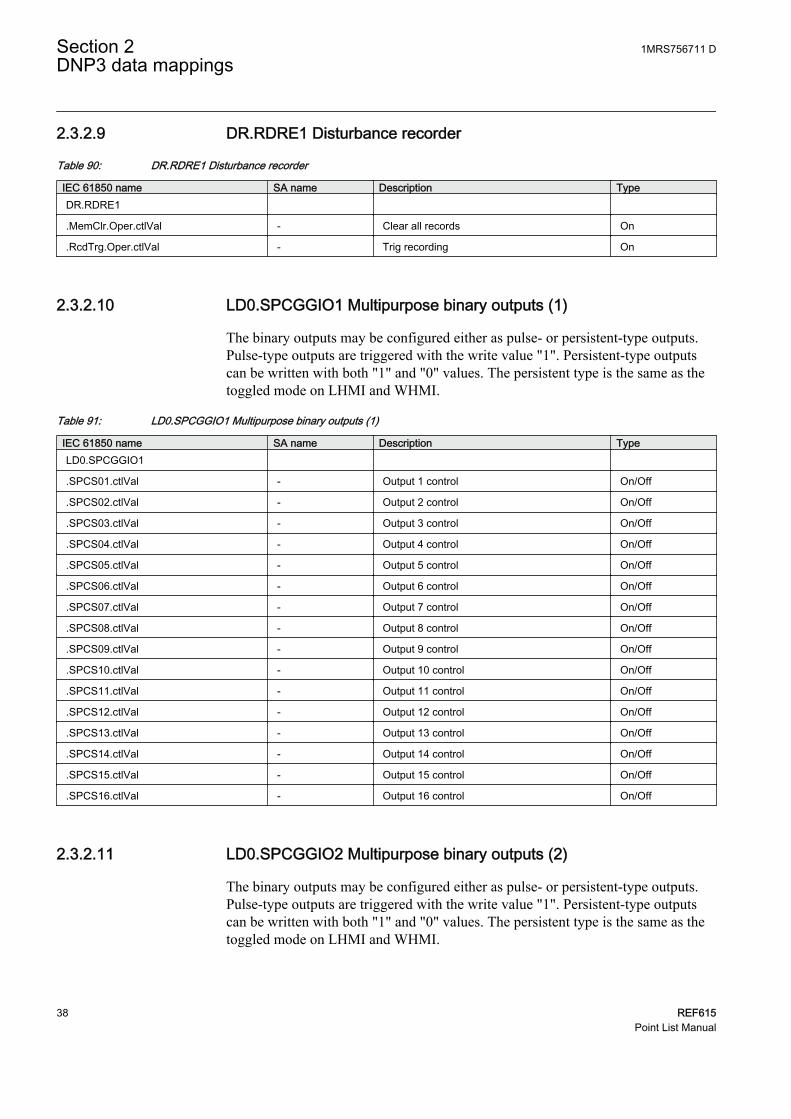
2.3.2.9 DR.RDRE1 Disturbance recorder
Table 90: DR.RDRE1 Disturbance recorder
IEC 61850 name SA name Description TypeDR.RDRE1
.MemClr.Oper.ctlVal - Clear all records On
.RcdTrg.Oper.ctlVal - Trig recording On
2.3.2.10 LD0.SPCGGIO1 Multipurpose binary outputs (1)
The binary outputs may be configured either as pulse- or persistent-type outputs.Pulse-type outputs are triggered with the write value "1". Persistent-type outputscan be written with both "1" and "0" values. The persistent type is the same as thetoggled mode on LHMI and WHMI.
Table 91: LD0.SPCGGIO1 Multipurpose binary outputs (1)
IEC 61850 name SA name Description TypeLD0.SPCGGIO1
.SPCS01.ctlVal - Output 1 control On/Off
.SPCS02.ctlVal - Output 2 control On/Off
.SPCS03.ctlVal - Output 3 control On/Off
.SPCS04.ctlVal - Output 4 control On/Off
.SPCS05.ctlVal - Output 5 control On/Off
.SPCS06.ctlVal - Output 6 control On/Off
.SPCS07.ctlVal - Output 7 control On/Off
.SPCS08.ctlVal - Output 8 control On/Off
.SPCS09.ctlVal - Output 9 control On/Off
.SPCS10.ctlVal - Output 10 control On/Off
.SPCS11.ctlVal - Output 11 control On/Off
.SPCS12.ctlVal - Output 12 control On/Off
.SPCS13.ctlVal - Output 13 control On/Off
.SPCS14.ctlVal - Output 14 control On/Off
.SPCS15.ctlVal - Output 15 control On/Off
.SPCS16.ctlVal - Output 16 control On/Off
2.3.2.11 LD0.SPCGGIO2 Multipurpose binary outputs (2)
The binary outputs may be configured either as pulse- or persistent-type outputs.Pulse-type outputs are triggered with the write value "1". Persistent-type outputscan be written with both "1" and "0" values. The persistent type is the same as thetoggled mode on LHMI and WHMI.
Section 2 1MRS756711 DDNP3 data mappings
38 REF615Point List Manual

Table 92: LD0.SPCGGIO2 Multipurpose binary outputs (2)
IEC 61850 name SA name Description TypeLD0.SPCGGIO2
.SPCS01.ctlVal - Output 1 control On/Off
.SPCS02.ctlVal - Output 2 control On/Off
.SPCS03.ctlVal - Output 3 control On/Off
.SPCS04.ctlVal - Output 4 control On/Off
.SPCS05.ctlVal - Output 5 control On/Off
.SPCS06.ctlVal - Output 6 control On/Off
.SPCS07.ctlVal - Output 7 control On/Off
.SPCS08.ctlVal - Output 8 control On/Off
.SPCS09.ctlVal - Output 9 control On/Off
.SPCS10.ctlVal - Output 10 control On/Off
.SPCS11.ctlVal - Output 11 control On/Off
.SPCS12.ctlVal - Output 12 control On/Off
.SPCS13.ctlVal - Output 13 control On/Off
.SPCS14.ctlVal - Output 14 control On/Off
.SPCS15.ctlVal - Output 15 control On/Off
.SPCS16.ctlVal - Output 16 control On/Off
2.3.2.12 LD0.SRGAPC1 Multipurpose binary outputs - flip-flop resets (1)
Table 93: LD0.SRGAPC1 Multipurpose binary outputs - flip-flop resets (1)
IEC 61850 name SA name Description TypeLD0.SRGAPC1
.Rs1.ctlVal - Reset flip-flop 1 On
.Rs2.ctlVal - Reset flip-flop 2 On
.Rs3.ctlVal - Reset flip-flop 3 On
.Rs4.ctlVal - Reset flip-flop 4 On
.Rs5.ctlVal - Reset flip-flop 5 On
.Rs6.ctlVal - Reset flip-flop 6 On
.Rs7.ctlVal - Reset flip-flop 7 On
.Rs8.ctlVal - Reset flip-flop 8 On
1MRS756711 D Section 2DNP3 data mappings
REF615 39Point List Manual

2.3.2.13 LD0.SRGAPC2 Multipurpose binary outputs - flip-flop resets (2)
Table 94: LD0.SRGAPC2 Multipurpose binary outputs - flip-flop resets (2)
IEC 61850 name SA name Description Type.Rs1.ctlVal - Reset flip-flop 1 On
.Rs2.ctlVal - Reset flip-flop 2 On
.Rs3.ctlVal - Reset flip-flop 3 On
.Rs4.ctlVal - Reset flip-flop 4 On
.Rs5.ctlVal - Reset flip-flop 5 On
.Rs6.ctlVal - Reset flip-flop 6 On
.Rs7.ctlVal - Reset flip-flop 7 On
.Rs8.ctlVal - Reset flip-flop 8 On
2.3.2.14 LD0.SSCBR1 Reset signals of CB condition monitoring
Table 95: LD0.SSCBR1 Reset signals of CB condition monitoring
IEC 61850 name SA name Description TypeLD0.SSCBR1
.RsAccAPwr.Oper.ctlVal RST_IPOW Reset accum. energy On
.RsCBWear.Oper.ctlVal RST_CB_WEAR Reset CB life and op. counter On
.RsSprChaTm.Oper.ctlVal RST_SPR_T Reset spring charge alarm On
.RsTrvTm.Oper.ctlVal RST_TRV_T Reset travel time alarm On
2.3.3 Analog inputsTable 96: Explanations of the analog input table columns
Column name DescriptionIEC 61850name
Original IED data object identification. Described in the IEC 61850 format asLogical Device.Logical Node and thereafter .Data Object.Data Attribute. LogicalNode is the same as the application function block name.
SA name The signal may have a defined label that is visible for example in ACT.
Description Short description of the signal. See the application function block documentationfor more details.
Values The value range of the original IEC 61850 data. Scaling is needed to convertfloating point data into DNP3 integer values.
S Scaling type selected as default. Default “R” means ratio scaling. See the DNPcommunication protocol manual for details.
Arg 1, 2, 3, 4 Scaling argument values as default. When ratio scaling is selected, the fourvalues correspond to min value in, max value in, min value out, and max valueout. See the DNP communication protocol manual for details.
Section 2 1MRS756711 DDNP3 data mappings
40 REF615Point List Manual

2.3.3.1 CTRL.CBCSWI1 CB 4-pole (2 bit) position value
Table 97: CTRL.CBCSWI1 CB 4-pole (2 bit) position value
IEC 61850 name SA name Description Values S Arg 1,2,3,4CTRL.CBCSWI1
.Pos.stVal POSITIONIntermediate=0; Off=1; On=2;Bad=3 0…3 R 0,3,0,3
2.3.3.2 LD0.CMMXU1 Phase currents (1)
Table 98: LD0.CMMXU1 Phase currents (1)
IEC 61850 name SA name Description Values S Arg 1,2,3,4LD0.CMMXU1 Phase-to-ground current
.A.phsA.instCVal.mag I_INST_A -phsA magnitude 0.00..40.0 [xIn] R 0,40,0,4000
.A.phsB.instCVal.mag I_INST_B -phsB magnitude 0.00..40.0 [xIn] R 0,40,0,4000
.A.phsC.instCVal.mag I_INST_C -phsC magnitude 0.00..40.0 [xIn] R 0,40,0,4000
2.3.3.3 LD0.CSMSQI1 Sequence of currents
Table 99: LD0.CSMSQI1 Sequence of currents
IEC 61850 name SA name Description Values S Arg 1,2,3,4LD0.CSMSQI1 Sequence of currents
.SeqA.c1.instCVal.mag I1_INST -Positive magnitude 0.00..40.0 [xIn] R 0,40,0,4000
.SeqA.c2.instCVal.mag I2_INST -Negative magnitude 0.00..40.0 [xIn] R 0,40,0,4000
.SeqA.c3.instCVal.mag I3_INST -Zero magnitude 0.00..40.0 [xIn] R 0,40,0,4000
2.3.3.4 LD0.DARREC1 Autoreclosing values
Table 100: LD0.DARREC1 Autoreclosing values
IEC 61850 name SA name Description Values S Arg 1,2,3,4LD0.DARREC1
.AutoRecSt.stVal STATUS Autorec. status -2…4 R -2,4,-2,4
.ShotPntr.stVal SHOT_PTR Shot pointer value 0…65535 R 0,65535,0,65535
2.3.3.5 CTRL.DCSXSWI1 Disconnector 1, 4-pole (2 bit) position values
Table 101: CTRL.DCSXSWI1 Disconnector 1, 4-pole (2 bit) position values
IEC 61850 name SA name Description Values S Arg 1,2,3,4CTRL.DCSXSWI1
.Pos.stVal POSITIONIntermediate=0; Off=1; On=2;Bad=3 0…3 R 0,3,0,3
1MRS756711 D Section 2DNP3 data mappings
REF615 41Point List Manual
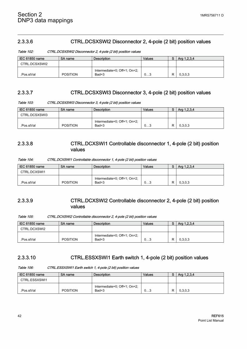
2.3.3.6 CTRL.DCSXSWI2 Disconnector 2, 4-pole (2 bit) position values
Table 102: CTRL.DCSXSWI2 Disconnector 2, 4-pole (2 bit) position values
IEC 61850 name SA name Description Values S Arg 1,2,3,4CTRL.DCSXSWI2
.Pos.stVal POSITIONIntermediate=0; Off=1; On=2;Bad=3 0…3 R 0,3,0,3
2.3.3.7 CTRL.DCSXSWI3 Disconnector 3, 4-pole (2 bit) position values
Table 103: CTRL.DCSXSWI3 Disconnector 3, 4-pole (2 bit) position values
IEC 61850 name SA name Description Values S Arg 1,2,3,4CTRL.DCSXSWI3
.Pos.stVal POSITIONIntermediate=0; Off=1; On=2;Bad=3 0…3 R 0,3,0,3
2.3.3.8 CTRL.DCXSWI1 Controllable disconnector 1, 4-pole (2 bit) positionvalues
Table 104: CTRL.DCXSWI1 Controllable disconnector 1, 4-pole (2 bit) position values
IEC 61850 name SA name Description Values S Arg 1,2,3,4CTRL.DCXSWI1
.Pos.stVal POSITIONIntermediate=0; Off=1; On=2;Bad=3 0…3 R 0,3,0,3
2.3.3.9 CTRL.DCXSWI2 Controllable disconnector 2, 4-pole (2 bit) positionvalues
Table 105: CTRL.DCXSWI2 Controllable disconnector 2, 4-pole (2 bit) position values
IEC 61850 name SA name Description Values S Arg 1,2,3,4CTRL.DCXSWI2
.Pos.stVal POSITIONIntermediate=0; Off=1; On=2;Bad=3 0…3 R 0,3,0,3
2.3.3.10 CTRL.ESSXSWI1 Earth switch 1, 4-pole (2 bit) position values
Table 106: CTRL.ESSXSWI1 Earth switch 1, 4-pole (2 bit) position values
IEC 61850 name SA name Description Values S Arg 1,2,3,4CTRL.ESSXSWI1
.Pos.stVal POSITIONIntermediate=0; Off=1; On=2;Bad=3 0…3 R 0,3,0,3
Section 2 1MRS756711 DDNP3 data mappings
42 REF615Point List Manual

2.3.3.11 CTRL.ESSXSWI2 Earth switch 2, 4-pole (2 bit) position values
Table 107: CTRL.ESSXSWI2 Earth switch 2, 4-pole (2 bit) position values
IEC 61850 name SA name Description Values S Arg 1,2,3,4CTRL.ESSXSWI2
.Pos.stVal POSITIONIntermediate=0; Off=1; On=2;Bad=3 0…3 R 0,3,0,3
2.3.3.12 CTRL.ESXSWI1 Controllable earth switch 1, 4-pole (2 bit) positionvalues
Table 108: CTRL.ESXSWI1 Controllable earth switch 1, 4-pole (2 bit) position values
IEC 61850 name SA name Description Values S Arg 1,2,3,4CTRL.ESXSWI1
.Pos.stVal POSITIONIntermediate=0; Off=1; On=2;Bad=3 0…3 R 0,3,0,3
2.3.3.13 LD0.DNPGGIO1 Active parameter setting group
Table 109: LD0.DNPGGIO1 Active parameter setting group
IEC 61850 name SA name Description Values S Arg 1,2,3,4LD0.DNPGGIO1
.ActSG.stVal - Active setting group 1…6 R 1,6,1,6
2.3.3.14 LD0.FMMXU1 Frequency measurement
Table 110: LD0.FMMXU1 Frequency measurement
IEC 61850 name SA name Description Values S Arg 1,2,3,4LD0.FMMXU1
.Hz.mag - Frequency value 35…75 [Hz] R 35,75,3500,7500
2.3.3.15 LD0.HAEFMHAI1 Current harmonics
Table 111: LD0.HAEFMHAI1 Current harmonics
IEC 61850 name SA name Description Values S Arg 1,2,3,4LD0.HAEFMHAI
.HRmsA.res.cVal.mag - Current harmonics 0…250 [A] R 0,250,0,250
1MRS756711 D Section 2DNP3 data mappings
REF615 43Point List Manual
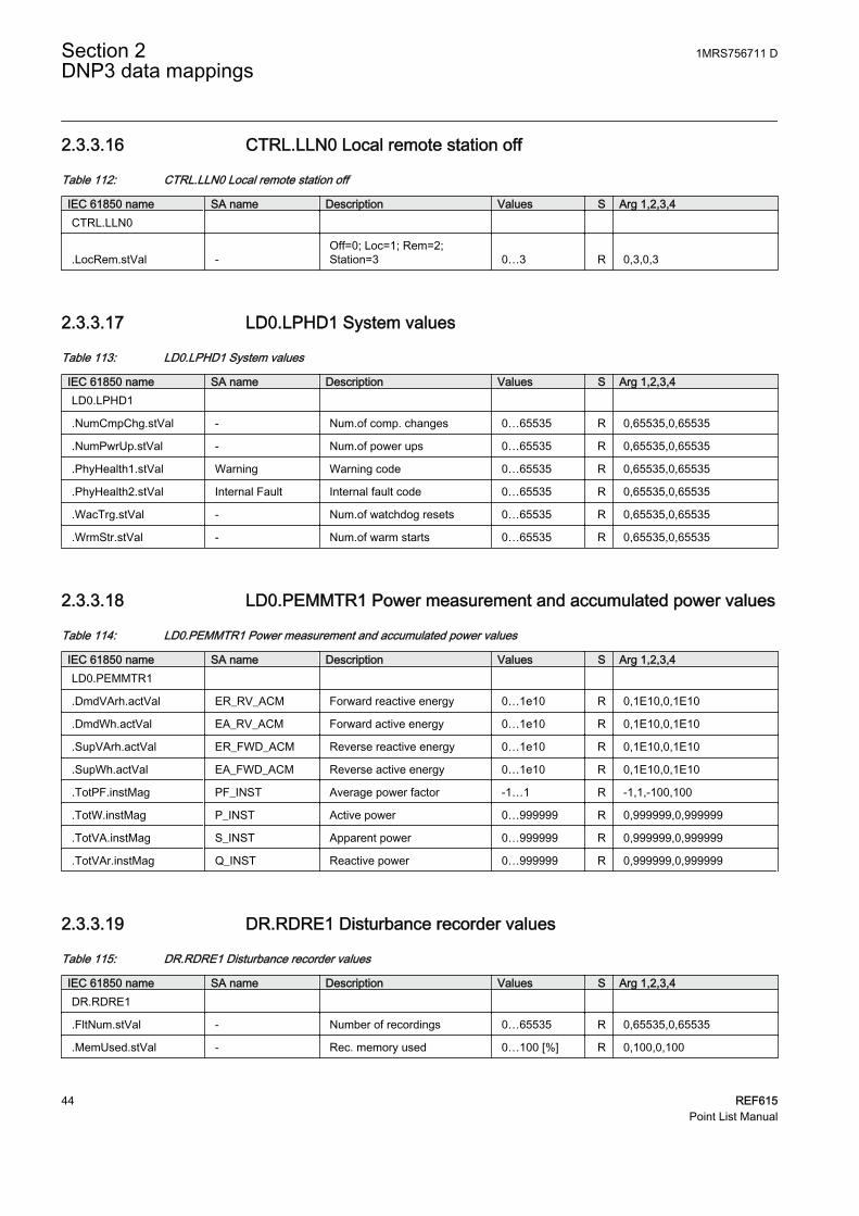
2.3.3.16 CTRL.LLN0 Local remote station off
Table 112: CTRL.LLN0 Local remote station off
IEC 61850 name SA name Description Values S Arg 1,2,3,4CTRL.LLN0
.LocRem.stVal -Off=0; Loc=1; Rem=2;Station=3 0…3 R 0,3,0,3
2.3.3.17 LD0.LPHD1 System values
Table 113: LD0.LPHD1 System values
IEC 61850 name SA name Description Values S Arg 1,2,3,4LD0.LPHD1
.NumCmpChg.stVal - Num.of comp. changes 0…65535 R 0,65535,0,65535
.NumPwrUp.stVal - Num.of power ups 0…65535 R 0,65535,0,65535
.PhyHealth1.stVal Warning Warning code 0…65535 R 0,65535,0,65535
.PhyHealth2.stVal Internal Fault Internal fault code 0…65535 R 0,65535,0,65535
.WacTrg.stVal - Num.of watchdog resets 0…65535 R 0,65535,0,65535
.WrmStr.stVal - Num.of warm starts 0…65535 R 0,65535,0,65535
2.3.3.18 LD0.PEMMTR1 Power measurement and accumulated power values
Table 114: LD0.PEMMTR1 Power measurement and accumulated power values
IEC 61850 name SA name Description Values S Arg 1,2,3,4LD0.PEMMTR1
.DmdVArh.actVal ER_RV_ACM Forward reactive energy 0…1e10 R 0,1E10,0,1E10
.DmdWh.actVal EA_RV_ACM Forward active energy 0…1e10 R 0,1E10,0,1E10
.SupVArh.actVal ER_FWD_ACM Reverse reactive energy 0…1e10 R 0,1E10,0,1E10
.SupWh.actVal EA_FWD_ACM Reverse active energy 0…1e10 R 0,1E10,0,1E10
.TotPF.instMag PF_INST Average power factor -1…1 R -1,1,-100,100
.TotW.instMag P_INST Active power 0…999999 R 0,999999,0,999999
.TotVA.instMag S_INST Apparent power 0…999999 R 0,999999,0,999999
.TotVAr.instMag Q_INST Reactive power 0…999999 R 0,999999,0,999999
2.3.3.19 DR.RDRE1 Disturbance recorder values
Table 115: DR.RDRE1 Disturbance recorder values
IEC 61850 name SA name Description Values S Arg 1,2,3,4DR.RDRE1
.FltNum.stVal - Number of recordings 0…65535 R 0,65535,0,65535
.MemUsed.stVal - Rec. memory used 0…100 [%] R 0,100,0,100
Section 2 1MRS756711 DDNP3 data mappings
44 REF615Point List Manual

2.3.3.20 LD0.RESCMMXU1 Residual current (1)
Table 116: LD0.RESCMMXU1 Residual current (1)
IEC 61850 name SA name Description Values S Arg 1,2,3,4LD0.RESCMMXU1
.A.res.instCVal.mag I0_INST Residual current 0.00..40.0 [xIn] R 0,40,0,4000
2.3.3.21 LD0.RESVMMXU1 Residual voltage (1)
Table 117: LD0.RESVMMXU1 Residual voltage (1)
IEC 61850 name SA name Description Values S Arg 1,2,3,4LD0.RESVMMXU1
.PhV.res.instCVal.mag U0_INST Residual voltage0.00..4.00[xUn] R 0,4,0,400
2.3.3.22 LD0.SECRSYN1 Synchrocheck line and bus state
Table 118: LD0.SECRSYN1 Synchrocheck line and bus state
IEC 61850 name SA name Description Values S Arg 1,2,3,4LD0.SECRSYN1
.EnSt.stVal - Energization state 0…4 R 0,4,0,4
2.3.3.23 LD0.T1PTTR1 Temperature protection values (1)
Table 119: LD0.T1PTTR1 Temperature protection values (1)
IEC 61850 name SA name Description Values S Arg 1,2,3,4LD0.T1PTTR1
.Tmp.mag - Object temperature -100…9999.9 R -100,9999.9.0,-1000,99999
.TmpRl.mag - Relative temperature 0…99.9 R 0,99.9,0,999
2.3.3.24 LD0.VMMXU1 Voltage measurement
Table 120: LD0.VMMXU1 Voltage measurement
IEC 61850 name SA name Description Values S Arg 1,2,3,4LD0.VMMXU1.PhV Phase-to-ground voltage
.phsA.cVal.mag U_DB_A -phsA magnitude0.00…4.00[xUn] R 0,4,0,400
.phsB.cVal.mag U_DB_B -phsB magnitude0.00…4.00[xUn] R 0,4,0,400
.phsC.cVal.mag U_DB_C -phsC magnitude0.00…4.00[xUn] R 0,4,0,400
Table continues on next page
1MRS756711 D Section 2DNP3 data mappings
REF615 45Point List Manual
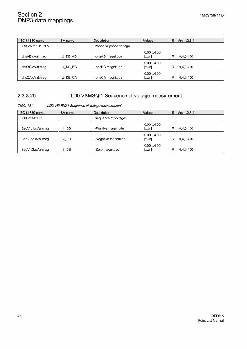
IEC 61850 name SA name Description Values S Arg 1,2,3,4LD0.VMMXU1.PPV Phase-to-phase voltage
.phsAB.cVal.mag U_DB_AB -phsAB magnitude0.00…4.00[xUn] R 0,4,0,400
.phsBC.cVal.mag U_DB_BC -phsBC magnitude0.00…4.00[xUn] R 0,4,0,400
.phsCA.cVal.mag U_DB_CA -phsCA magnitude0.00…4.00[xUn] R 0,4,0,400
2.3.3.25 LD0.VSMSQI1 Sequence of voltage measurement
Table 121: LD0.VSMSQI1 Sequence of voltage measurement
IEC 61850 name SA name Description Values S Arg 1,2,3,4LD0.VSMSQI1 Sequence of voltages
.SeqV.c1.cVal.mag I1_DB -Positive magnitude0.00…4.00[xUn] R 0,4,0,400
.SeqV.c2.cVal.mag I2_DB -Negative magnitude0.00…4.00[xUn] R 0,4,0,400
.SeqV.c3.cVal.mag I3_DB -Zero magnitude0.00…4.00[xUn] R 0,4,0,400
Section 2 1MRS756711 DDNP3 data mappings
46 REF615Point List Manual

Section 3 DNP3 protocol implementation
3.1 DNP3 device profile
The following table provides a device profile document in the standard formatdefined in the DNP3 Subset Definitions Document. In the DNP3 SubsetDefinitions Document it is referred to as a document, although it is in fact a tableand only a component of a total interoperability guide. The table, in combinationwith the Implementation table and the point list tables, provides a completeconfiguration/interoperability guide for communicating with a device.
Table 122: Device profile document
DNP3 device profile documentVendor name: ABB Oy
Device name: REF615
Highest DNP level supported: Device function:
For requests: Level 2+ ○ Master
For responses: Level 2+ ● Slave
Notable objects, functions, and/or qualifiers supported in addition to the highest DNP levels supported (the complete list is described inthe attached table):For static (non-change-event) object requests, request qualifier codes 07 and 08 (limited quantity), and 17 and 28 (index) are supported.Static object requests sent with qualifiers 07, or 08, will be responded with qualifiers 00 or 01.16-bit and 32-bit Analog Change Events with Time may be requested.
Maximum data link frame size (octets): Maximum application fragment size (octets):
Transmitted: 292 Transmitted: Configurable (256...2048)
Received: 292 Received: 2048
Maximum data link re-tries: Maximum application layer re-tries:
○ None ● None
○ Fixed ○ Configurable
● Configurable (0...65535)
Requires data link layer confirmation:
○ Never
○ Always
○ Sometimes
● Configurable as: "Never", "Only for multi-frame messages", or "Always"
Requires application layer confirmation:
○ Never
○ Always
○ When reporting event data (slave devices only)
○ When sending multi-fragment responses (slave devices only)
Table continues on next page
1MRS756711 D Section 3DNP3 protocol implementation
REF615 47Point List Manual

DNP3 device profile document ○ Sometimes
● Configurable as: "Only when reporting event data", or "When reporting event data or multi-fragment messages"
Timeouts while waiting for:
Data linkconfirm:
○ None ○ Fixed at ____ ○ Variable ● Configurable
Completeappl. fragment:
● None ○ Fixed at ____ ○ Variable ○ Configurable
Applicationconfirm:
○ None ○ Fixed at ____ ○ Variable ● Configurable
Completeappl.response:
● None ○ Fixed at ____ ○ Variable ○ Configurable
Others: Select/Operate Arm timeout, configurable in DNP setting parameters. Regrdless of the select timeout in the HMI.Need time interval, configurableUnsolicited notification delay, configurableUnsolicited response retry delay, configurableUnsolicited offline Interval, configurable
Sends/Executes Control Operations:
WRITE binaryoutputs
● Never ○ Always ○ Sometimes ○ Configurable
SELECT/OPERATE
○ Never ○ Always ○ Sometimes ● Configurable
DIRECTOPERATE
○ Never ○ Always ○ Sometimes ● Configurable
DIRECTOPERATE -NO ACK
○ Never ○ Always ○ Sometimes ● Configurable
Count > 1(Count > 1 isaccepted butignored)
● Never ○ Always ○ Sometimes ○ Configurable
Pulse on ● Never ○ Always ○ Sometimes ○ Configurable
Pulse off ● Never ○ Always ○ Sometimes ○ Configurable
Latch on ○ Never ● Always ○ Sometimes ○ Configurable
Latch off ○ Never ● Always ○ Sometimes ○ Configurable
Queue ● Never ○ Always ○ Sometimes ○ Configurable
Clear queue ● Never ○ Always ○ Sometimes ○ Configurable
The circuit breaker control model is configurable for either direct or SBO mode in the circuit breaker settings. If the operation mode doesnot match the CROB, the returned CROB status is hardware error (4). All other control points may be controlled by either direct or SBOcontrols.
Reports binary input change events when no specific variationrequested:
Reports time-tagged binary input change events when no specificvariation requested:
○ Never ○ Never
○ Only when time-tagged ○ Binary input change with time
○ Only non-time-tagged ○ Binary input change with relative time
● Configurable to send one or the other ● Configurable
Sends unsolicited responses: Sends static data in unsolicited responses:
● Never ● Never
Table continues on next page
Section 3 1MRS756711 DDNP3 protocol implementation
48 REF615Point List Manual

DNP3 device profile document ○ Configurable ○ When device restarts
○ Only certain objects ○ When status flags change
○ Sometimes (attach explanation)
○ ENABLE/DISABLE UNSOLICITEDfunction codes supported
No other options are permitted.
Default counter object/variation: Counters roll over at:
● No counters reported ● No counters reported
○ Configurable ○ Configurable (attach explanation)
○ Default objectDefault variation:
○ 16 bits
○ Point-by-point list attached ○ 32 bits
○ Other value: _______
○ Point-by-point list attached
Sends multi-fragment responses:
● Yes
○ No
○ Configurable
Sequential file transfer support:
Append file mode ○ Yes ● No
Custom status code strings ○ Yes ● No
Permissions field ○ Yes ● No
File events assigned to class ○ Yes ● No
File events send immediately ○ Yes ● No
Multiple blocks in a fragment ○ Yes ● No
Max number of files open 0
● = Selected,○ = Not selected
3.2 DNP3 implementation table
The following table identifies which object variations, function codes andqualifiers the IED supports in both request messages and response messages. Forstatic (non-change-event) objects, requests sent with qualifiers 00, 01, 06, 07 or 08are responded with qualifiers 00 or 01. Requests sent with qualifiers 17 or 28 areresponded with qualifiers 17 or 28. For change-event objects, qualifiers 17 or 28are always responded.
1MRS756711 D Section 3DNP3 protocol implementation
REF615 49Point List Manual

Table 123: Implementation table
OBJECT REQUEST (Library will parse) RESPONSE (Library will respond with)Objectnumber
Variationnumber Description Function codes (dec) Qualifier codes (hex)
Function codes(dec)
Qualifier codes(hex)
1 0 Binaryinput – anyvariation
1 (read)22 (assign class)
00, 01 (start-stop)06 (no range, or all)07, 08 (limited qty)17, 28 (index)
1 1 (default) 1) Binaryinput
1 (read) 00, 01 (start-stop)06 (no range, or all)07, 08 (limited qty)17, 28 (index)
129 (response) 00, 01 (start-stop)17, 28 (index) 2)
1 2 Binaryinput with
status
1 (read) 00, 01 (start-stop)06 (no range, or all)07, 08 (limited qty)17, 28 (index)
129 (response) 00, 01 (start-stop)17, 28 (index) 2)
2 0 Binaryinput
change –any
variation
1 (read) 06 (no range, or all)07, 08 (limited qty)
2 1 Binaryinput
changewithout
time
1 (read) 06 (no range, or all)07, 08 (limited qty)
129 (response)130 (unsol. resp)
17, 28 (index)
2 21) Binaryinput
changewith time
1 (read) 06 (no range, or all)07, 08 (limited qty)
129 (response)130 (unsol. resp)
17, 28 (index)
2 3 Binaryinput
changewith
relativetime
1 (read) 06 (no range, or all)07, 08 (limited qty)
129 (response)130 (unsol. resp)
17, 28 (index)
10 0 Binaryoutput
status –any
variation
1 (read) 00, 01 (start-stop)06 (no range, or all)07, 08 (limited qty)17, 28 (index)
10 1 Binaryoutput
1 (read) 00, 01 (start-stop)06 (no range, or all)07, 08 (limited qty)17, 28 (index)
129 (response) 00, 01 (start-stop)17, 28 (index) 2)
12 1 Controlrelay
outputblock
3 (select)4 (operate)5 (direct op)6 (dir. op, noack)
17, 28 (index) 129 (response) echo of request
30 0 Analoginput - anyvariation
1 (read)22 (assign class)
00, 01 (start-stop)06 (no range, or all)07, 08 (limited qty)17, 28 (index)
30 1 32-bitanaloginput
1 (read) 00, 01 (start-stop)06 (no range, or all)07, 08 (limited qty)17, 28 (index)
129 (response) 00, 01 (start-stop)17, 28 (index) 2)
Table continues on next page
Section 3 1MRS756711 DDNP3 protocol implementation
50 REF615Point List Manual

OBJECT REQUEST (Library will parse) RESPONSE (Library will respond with)30 2 (default) 1) 16-bit
analoginput
1 (read) 00, 01 (start-stop)06 (no range, or all)07, 08 (limited qty)17, 28 (index)
129 (response) 00, 01 (start-stop)17, 28 (index) 2)
30 3 32-bitanaloginput
without flag
1 (read) 00, 01 (start-stop)06 (no range, or all)07, 08 (limited qty)17, 28 (index)
129 (response) 00, 01 (start-stop)17, 28 (index) 2)
30 4 16-bitanaloginput
without flag
1 (read) 00, 01 (start-stop)06 (no range, or all)07, 08 (limited qty)17, 28 (index)
129 (response) 00, 01 (start-stop)17, 28 (index) 2)
32 0 Analogchangeevent –
anyvariation
1 (read) 06 (no range, or all)07, 08 (limited qty)
32 1 32-bitanalogchangeevent
withouttime
1 (read) 06 (no range, or all)07, 08 (limited qty)
129 (response)130 (unsol. resp)
17, 28 (index)
32 2 16-bitanalogchangeevent
withouttime
1 (read) 06 (no range, or all)07, 08 (limited qty)
129 (response)130 (unsol. resp)
17, 28 (index)
32 3 32-bitanalogchange
event withtime
1 (read) 06 (no range, or all)07, 08 (limited qty)
129 (response)130 (unsol. resp)
17, 28 (index)
32 4 (default) 1) 16-bitanalogchange
event withtime
1 (read) 06 (no range, or all)07, 08 (limited qty)
129 (response)130 (unsol. resp)
17, 28 (index)
50 0 Time anddate
50 1 (default) 1) Time anddate
1 (read) 00, 01 (start-stop)06 (no range, or all)07 (limited qty = 1l)08 (limited qty)
129 (response) 00, 01 (start-stop)17, 28 (index) 2)
2 (write) 07 (limited qty = 1l)
50 3 Time anddate lastrecorded
time
2 (write) 07 (limited qty)
51 1 Time anddate CTO
129 (response)130 (unsol. resp)
07 (limited qty)(qty = 1)
51 2 Unsynchronized timeand date
CTO
129 (response)130 (unsol. resp)
07 (limited qty)(qty = 1)
Table continues on next page
1MRS756711 D Section 3DNP3 protocol implementation
REF615 51Point List Manual
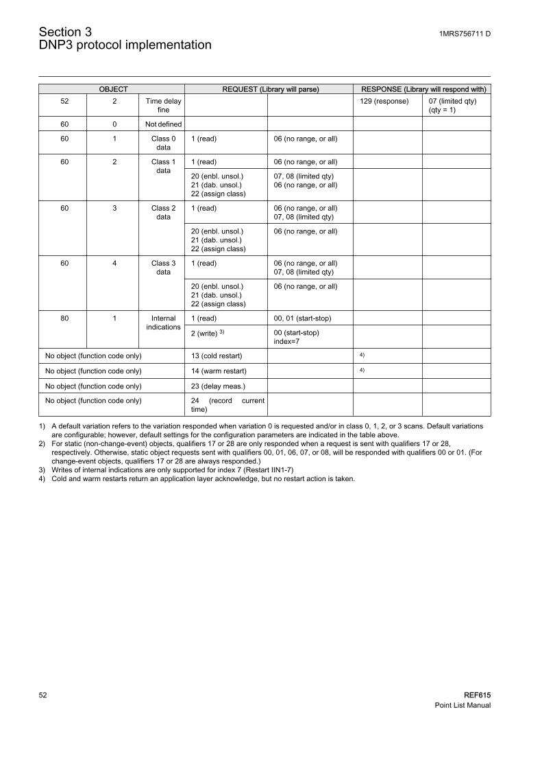
OBJECT REQUEST (Library will parse) RESPONSE (Library will respond with)52 2 Time delay
fine 129 (response) 07 (limited qty)
(qty = 1)
60 0 Not defined
60 1 Class 0data
1 (read) 06 (no range, or all)
60 2 Class 1data
1 (read) 06 (no range, or all)
20 (enbl. unsol.)21 (dab. unsol.)22 (assign class)
07, 08 (limited qty)06 (no range, or all)
60 3 Class 2data
1 (read) 06 (no range, or all)07, 08 (limited qty)
20 (enbl. unsol.)21 (dab. unsol.)22 (assign class)
06 (no range, or all)
60 4 Class 3data
1 (read) 06 (no range, or all)07, 08 (limited qty)
20 (enbl. unsol.)21 (dab. unsol.)22 (assign class)
06 (no range, or all)
80 1 Internalindications
1 (read) 00, 01 (start-stop)
2 (write) 3) 00 (start-stop)index=7
No object (function code only) 13 (cold restart) 4)
No object (function code only) 14 (warm restart) 4)
No object (function code only) 23 (delay meas.)
No object (function code only) 24 (record currenttime)
1) A default variation refers to the variation responded when variation 0 is requested and/or in class 0, 1, 2, or 3 scans. Default variationsare configurable; however, default settings for the configuration parameters are indicated in the table above.
2) For static (non-change-event) objects, qualifiers 17 or 28 are only responded when a request is sent with qualifiers 17 or 28,respectively. Otherwise, static object requests sent with qualifiers 00, 01, 06, 07, or 08, will be responded with qualifiers 00 or 01. (Forchange-event objects, qualifiers 17 or 28 are always responded.)
3) Writes of internal indications are only supported for index 7 (Restart IIN1-7)4) Cold and warm restarts return an application layer acknowledge, but no restart action is taken.
Section 3 1MRS756711 DDNP3 protocol implementation
52 REF615Point List Manual

Section 4 Glossary
615 series Series of numerical IEDs for low-end protection andsupervision applications of utility substations, and industrialswitchgear and equipment
CROB Control relay output blockCTO Common time of occurrence. The time and date CTO object is
an information object that represents the absolute time of day.DNP3 A distributed network protocol originally developed by
Westronic. The DNP3 Users Group has the ownership of theprotocol and assumes responsibility for its evolution.
EMC Electromagnetic compatibilityHMI Human-machine interfaceIEC International Electrotechnical CommissionIEC 61850 International standard for substation communication and
modelingIED Intelligent electronic deviceIET600 Integrated Engineering Toolbox in PCM600LHMI Local human-machine interfacePCM600 Protection and Control IED ManagerSBO Select-before-operate
1MRS756711 D Section 4Glossary
REF615 53Point List Manual

54

55


Contact us
ABB OyDistribution AutomationP.O. Box 699FI-65101 VAASA, FinlandPhone +358 10 22 11Fax +358 10 22 41094
www.abb.com/substationautomation
1MR
S75
6711
D©
Cop
yrig
ht 2
012
AB
B. A
ll rig
hts
rese
rved
.