division of air quality geneva nitrogen uc - utah · pdf fileplease find enclosed the bact...
TRANSCRIPT

UTAH DEPARTMENT OF ENVIRONMENTAL QUALITY
MAY 2 6 2017
Geneva Nitrogen ucDIVISION OF AIR QUALITY
May 22, 2017
Nando Meli Division of Air Quality Department of Environmental Quality
PO Box 144820 Salt Lake City, UT 84114-4820
RE: BACT Analysis for Geneva Nitrogen
Dear Mr. Meli,
Please find enclosed the BACT analysis requested by the Utah Division of Air Quality. Thank you for extending some additional time beyond your desired May 1 goal to complete this analysis. As you might imagine it has taken some effort to gather the
required information from various suppliers etc. to ensure the information is as accurate
as possible.
Please let me know if there are any questions or if you desire to discuss this issue
further.
Best regards,
Steven Thompson
Vice President & General Manager
Documcnl Dale: 05/22/2017
DAQ-2017 007289
1165 North 1600 West, Vineyard, UT 84057 PHONE 801-227-7300 FAX 801-227-7303
UTAH DEPARTMENT OF ENVIRONMENTAL QUALITY
MAY 2 6 2017
Geneva Nitrogen LLC division of air quality
PM 2.5 SIP Major Point Source BACT Information
Submitted: May 22, 2017
Site and Company Information:
Geneva Nitrogen LLC is located at 1165 North 1600 West, Vineyard, Utah County, in the state of Utah. The plant’s UTM coordinates are Easting 447.607, Northing 4463.833.
Recent Permitting Actions:
1. Approval Orders:a. DAQE-AN825005-03 approved on December 9, 2003.
2. Title V Permit:a. Permit Number 4900082004 effective August 8, 2013.
3. SIP Submittal:a. Geneva Nitrogen was listed under the 2005 State Implementation Plan submittal.
Description of Facility:
Geneva Nitrogen LLC manufactures solid ammonium nitrate (prill) in a three step process:1. Nitric acid production2. Ammonium nitrate solution production3. Solid ammonium nitrate production
The following will describe each of these processes in detail
Nitric Acid Manufacturing Process
Geneva Nitrogen utilizes two independent nitric acid production facilities, Montecatini and Weatherly, for the production of “weak” nitric acid. “Weak” nitric acid refers to acid production between 30 and 70 percent concentration. Each of these facilities produce nitric acid concentrated to 54 percent. (Refer to site plan in Appendix Section, Appendix 1 for facility locations).
Nitric acid production is accomplished in three major steps (refer to Appendix B-2 & Appendix B- 3 in Appendix Section):
1. High temperature catalytic oxidation of ammonia.
1
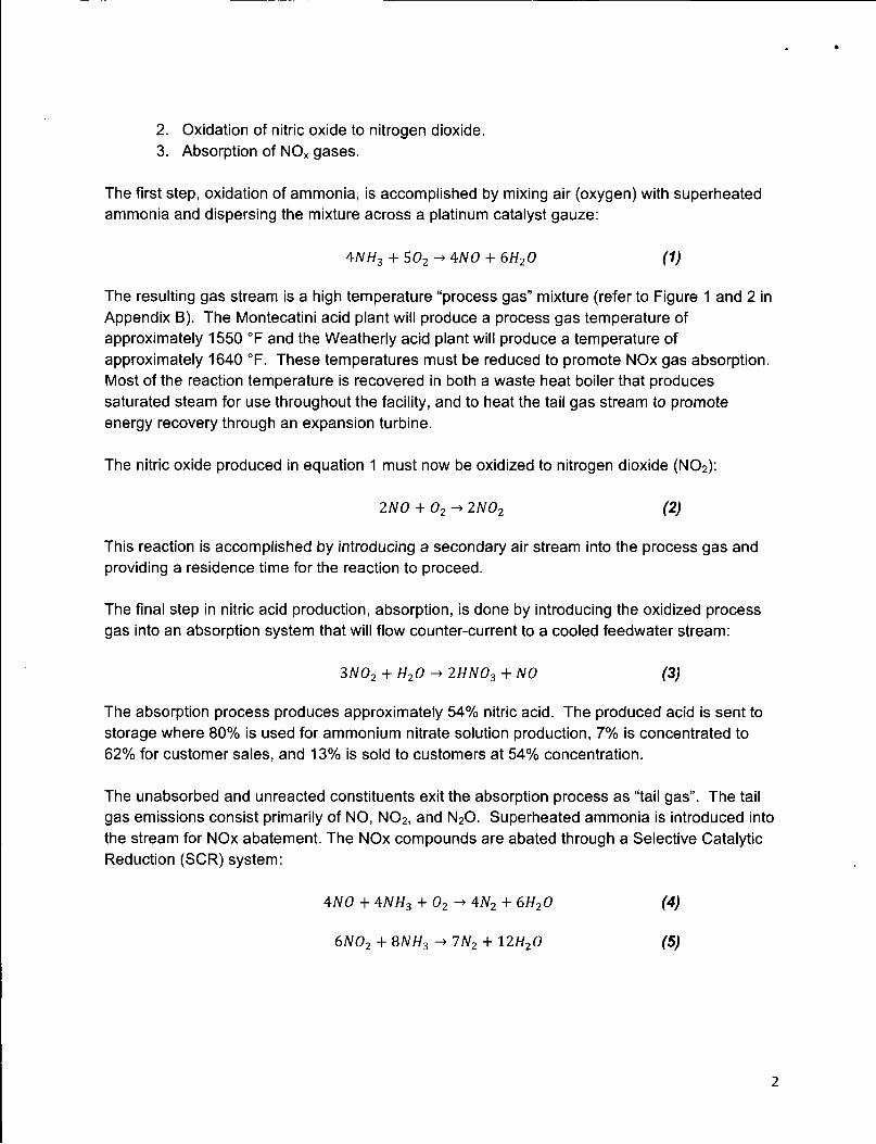
2. Oxidation of nitric oxide to nitrogen dioxide.3. Absorption of NOx gases.
The first step, oxidation of ammonia, is accomplished by mixing air (oxygen) with superheated ammonia and dispersing the mixture across a platinum catalyst gauze:
ANH3 + 502 ^ 4yV0 + 6H20 (1)
The resulting gas stream is a high temperature “process gas” mixture (refer to Figure 1 and 2 in Appendix B). The Montecatini acid plant will produce a process gas temperature of approximately 1550 °F and the Weatherly acid plant will produce a temperature of approximately 1640 °F. These temperatures must be reduced to promote NOx gas absorption. Most of the reaction temperature is recovered in both a waste heat boiler that produces saturated steam for use throughout the facility, and to heat the tail gas stream to promote energy recovery through an expansion turbine.
The nitric oxide produced in equation 1 must now be oxidized to nitrogen dioxide (N02):
2NO + 02^ 2N02 (2)
This reaction is accomplished by introducing a secondary air stream into the process gas and providing a residence time for the reaction to proceed.
The final step in nitric acid production, absorption, is done by introducing the oxidized process gas into an absorption system that will flow counter-current to a cooled feedwater stream:
3N02 + H20 -> 2HN03 + NO (3)
The absorption process produces approximately 54% nitric acid. The produced acid is sent to storage where 80% is used for ammonium nitrate solution production, 7% is concentrated to 62% for customer sales, and 13% is sold to customers at 54% concentration.
The unabsorbed and unreacted constituents exit the absorption process as “tail gas”. The tail gas emissions consist primarily of NO, N02, and N20. Superheated ammonia is introduced into the stream for NOx abatement. The NOx compounds are abated through a Selective Catalytic Reduction (SCR) system:
4yV0+4yV//3 + O2^4JV2 + 6//20 (4)
6N02 + 8NH3 -> 7N2 + 12H20 (5)
2

Air Pollution Control Technology, Selective Catalytic Reduction (SCR)
Geneva Nitrogen LLC controls NOx emissions from the nitric acid plants using a Selective Catalytic Reduction system (SCR). This system consists of a reaction vessel containing a proprietary zeolite-based catalyst, an ammonia superheater, an ammonia/tail gas mixer, and instrumentation to monitor and control the system.
Gaseous ammonia is superheated to approximately 300-350 °F before being mixed with the NOx laden tail gas. This ammonia/tail gas mixture flows through the catalytic reactor, converting the NOx into nitrogen and water before being exhausted to the atmosphere.
The ammonia flow into the tail gas is automatically controlled based on the reactor outlet NOx content. The NOx reduction is monitored by analyzers both upstream and downstream of the reactor vessel. These analyzers are used to record and report emissions regulation compliance.
Acid Process Raw Materials/Fuels:
Anhydrous ammonia is received by railcar. The ammonia is offloaded into two 2100 ton storage tanks.
Hydrogen gas (fuel), received in pressurized 150 lb cylinders, is used as an ignition source for the catalyst gauze during start-up (5-10 minute period). Once start-up is complete the hydrogen gas is no longer needed.
Acid Process Production Rates:
AO# DAQE-AN0825005-03 limits Geneva Nitrogen LLC’s nitric acid production to 13.5 tons per hour and 113,400 tons year (100% acid basis).
Acid Process Operating Schedule:
AO# DAQE-AN0825005-03 limits Geneva Nitrogen LLC’s operational schedule to 8640 hours
per year.
3
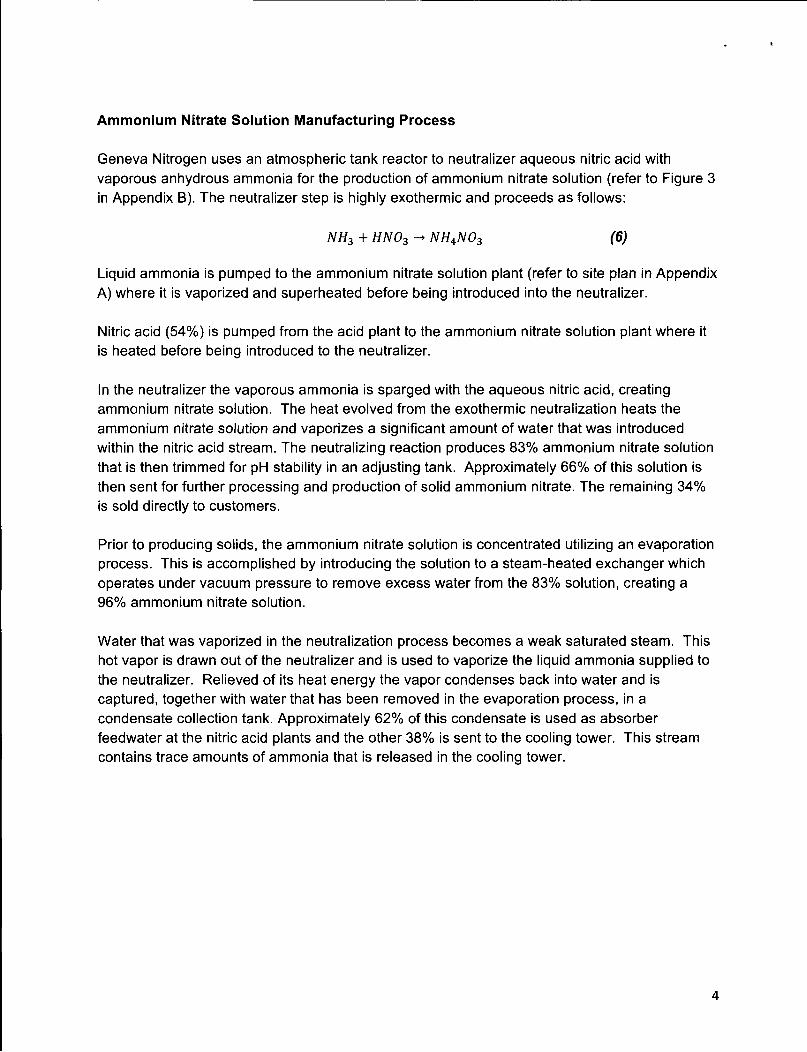
Ammonium Nitrate Solution Manufacturing Process
Geneva Nitrogen uses an atmospheric tank reactor to neutralizer aqueous nitric acid with vaporous anhydrous ammonia for the production of ammonium nitrate solution (refer to Figure 3 in Appendix B). The neutralizer step is highly exothermic and proceeds as follows:
NH3 + HN03 -» NH4N03 (6)
Liquid ammonia is pumped to the ammonium nitrate solution plant (refer to site plan in Appendix A) where it is vaporized and superheated before being introduced into the neutralizer.
Nitric acid (54%) is pumped from the acid plant to the ammonium nitrate solution plant where it is heated before being introduced to the neutralizer.
In the neutralizer the vaporous ammonia is sparged with the aqueous nitric acid, creating ammonium nitrate solution. The heat evolved from the exothermic neutralization heats the ammonium nitrate solution and vaporizes a significant amount of water that was introduced within the nitric acid stream. The neutralizing reaction produces 83% ammonium nitrate solution that is then trimmed for pH stability in an adjusting tank. Approximately 66% of this solution is then sent for further processing and production of solid ammonium nitrate. The remaining 34% is sold directly to customers.
Prior to producing solids, the ammonium nitrate solution is concentrated utilizing an evaporation process. This is accomplished by introducing the solution to a steam-heated exchanger which operates under vacuum pressure to remove excess water from the 83% solution, creating a 96% ammonium nitrate solution.
Water that was vaporized in the neutralization process becomes a weak saturated steam. This hot vapor is drawn out of the neutralizer and is used to vaporize the liquid ammonia supplied to the neutralizer. Relieved of its heat energy the vapor condenses back into water and is captured, together with water that has been removed in the evaporation process, in a condensate collection tank. Approximately 62% of this condensate is used as absorber feedwater at the nitric acid plants and the other 38% is sent to the cooling tower. This stream contains trace amounts of ammonia that is released in the cooling tower.
4

Air Pollution Control Technology, None Adopted
Geneva Nitrogen LLC does not control PM2.5 emissions within the ammonium nitrate solutions process as the AN solution evaporator steam ejector is considered an insignificant emissions source. (See Insignificant Emissions within Sources, this document page 14)
AN Solution Raw Materials/Fuels:
• Ammonia is supplied from the ammonia storage tanks• Nitric acid is supplied from the 54% nitric acid storage tank
All raw materials received, handled, and introduced into the neutralization process produce zero or insignificant emissions.
AN Solution Production Rates:
Since this is an intermediate step, no production limits have been specifically placed on this process. Limits have been placed on the quantity of solid ammonium nitrate that can be produced per hour and year.
AN Solution Operating Schedule:
AO# DAQE-AN0825005-03 limits Geneva Nitrogen LLC’s operational schedule to 8640 hours
per year.
5

Ammonium Nitrate Solids Manufacturing Process
Solid ammonium nitrate production (prill) consists of prill formation, prill finishing, prill coating, and prill bulk shipment (refer to Figure 4 in Appendix B).
To produce solid ammonium nitrate (prill), the concentrated 96% ammonium nitrate solution is pumped to a head tank located at the top of the prill tower. In the head tank, the solution is mixed with an ammonium sulfate based crystal modifier, referred to by its trade name “Sapphyr”, to aid in the formation of the prill. Once mixed, the ammonium nitrate solution is dispersed through a manifold that will distribute the solution to spray heads. These spray heads allow the solution to fall down the tower at a controlled rate. In the tower, the ammonium nitrate solution droplets are cooled by a counter-current flow of ambient air, creating a solid spherical prill.
The temperature of the prill at the bottom of the tower is approximately 180 °F and contains approximately 3% moisture. In order to prevent deterioration and agglomeration the prill must be dried and cooled in three separate rotary drums: Pre-Dryer, Dryer, and Cooler.
The pre-dryer is designed to “condition” the prill and start the process of removing the water.The dryer is designed to remove the moisture from the prill. The cooler is designed to cool the prill to an adequate temperature.
All three rotary drums use a counter-current flow of air to remove moisture and cool the prill. After leaving the drum, this air stream is sent through a wet scrubbing system to remove entrained ammonium nitrate fines before being emitted to the atmosphere.
Following the drying and cooling process, the prill is then externally coated with a paraffin based hydrophobic compound, referred to by its trade name “Galoryl”, to further prevent agglomeration before being sent to the ammonium nitrate warehouse for bulk storage.
Emissions from the solids formation process consist mainly of ammonium nitrate particulate matter and ammonia. The major source of ammonium nitrate particulates is the uncontrolled emission from the prill tower. Ammonium nitrate particulate matter is also emitted from the coating, bulk transfer, and loading operations.
Fugitive emissions are emitted to the atmosphere through open doors and building vents in the storage warehouse. Small quantities of fugitive emissions are generated when loading the bulk ammonium nitrate into truck and rail cars.
6
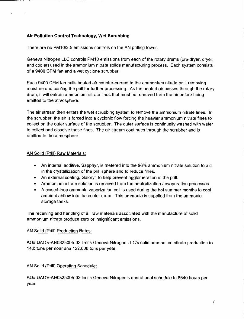
Air Pollution Control Technology, Wet Scrubbing
There are no PM 10/2.5 emissions controls on the AN prilling tower.
Geneva Nitrogen LLC controls PM 10 emissions from each of the rotary drums (pre-dryer, dryer, and cooler) used in the ammonium nitrate solids manufacturing process. Each system consists of a 9400 CFM fan and a wet cyclone scrubber.
Each 9400 CFM fan pulls heated air counter-current to the ammonium nitrate prill, removing moisture and cooling the prill for further processing. As the heated air passes through the rotary drum, it will entrain ammonium nitrate fines that must be removed from the air before being emitted to the atmosphere.
The air stream then enters the wet scrubbing system to remove the ammonium nitrate fines. In the scrubber, the air is forced into a cyclonic flow forcing the heavier ammonium nitrate fines to collect on the outer surface of the scrubber. The outer surface is continually washed with water to collect and dissolve these fines. The air stream continues through the scrubber and is emitted to the atmosphere.
AN Solid (Prill) Raw Materials:
• An internal additive, Sapphyr, is metered into the 96% ammonium nitrate solution to aid in the crystallization of the prill sphere and to reduce fines.
• An external coating, Galoryl, to help prevent agglomeration of the prill.• Ammonium nitrate solution is received from the neutralization / evaporation processes.• A closed-loop ammonia vaporization coil is used during the hot summer months to cool
ambient airflow into the cooler drum. This ammonia is supplied from the ammonia storage tanks.
The receiving and handling of all raw materials associated with the manufacture of solid ammonium nitrate produce zero or insignificant emissions.
AN Solid (Prill) Production Rates:
AO# DAQE-AN0825005-03 limits Geneva Nitrogen LLC’s solid ammonium nitrate production to 14.0 tons per hour and 122,600 tons per year.
AN Solid (Prill) Operating Schedule:
AO# DAQE-AN0825005-03 limits Geneva Nitrogen’s operational schedule to 8640 hours per
year.
7

Natural Gas Fired Auxiliary Boiler Steam Process
Steam is an essential component in the production of both nitric acid and ammonium nitrate. It is used throughout the facility as a heating media in applications such as heat exchangers, vacuum ejectors, steam trace, steam jacketing, building area heaters, etc. The nitric acid plants produce a large amounts of waste heat, steam derived from the catalytic reaction within the nitric acid process, which is low cost compared to other sources of steam.
When the acid plants are shut down for maintenance or inventory related curtailment, a gas- fired package boiler supplies steam to support heat-sensitive processes such as AN solution truck loading, AN solution storage, building heat, etc. On several occasions, when both acid plants are shut down and acid inventory is high, ammonium nitrate production is continued using steam generated by the gas-fired package boiler.
Geneva Nitrogen owns / operates a horizontal, 4 pass firetube boiler (25.0 MM Btu/hr). In a firetube steam boiler, heat and gases of combustion pass through tubes submerged (surrounded) in boiler feedwater. Heat is transferred from gas to water to produce saturated steam which is used in plant processes.
The only fuel of combustion utilized by the package boiler is natural gas. The boiler controls have been designed for natural gas operation, specifically, optimization of the air to fuel ratio control. The boiler controls would have to be significantly altered in order to efficiently operate on an alternate fuel source such as fuel oil.
The gas-fired boiler is of older design and therefore has no emissions controls. Modern package boilers come with a variety of NOx control options; post combustion (abatement) methods and combustion control techniques. Post combustion methods address NOx emissions after formation while combustion control techniques prevent the formation of NOx during the combustion process. The following is a list of different NOx control methods:
Post Combustion Control Methods (Abatement)1. Selective Non-Catalytic Reduction (NSCR)2. Selective Catalytic Reduction (SCR)
Combustion Control Techniques1. Low excess air firing2. Low nitrogen fuel oil3. Burner modification (Low NOx)4. Water / Steam injection5. Flue gas recirculation
Each method results in a different degree of NOx control; low excess air firing typically reduces NOx by 10%, flue gas recirculation by 75%, and selective catalytic reduction by 90%.
8

Air Pollution Control Technology, Natural Gas Fired Boiler
There are no NOx emissions controls on the natural gas-fired package boiler owned and operated by Geneva Nitrogen.
Geneva Nitrogen limits boiler NOx emissions by yearly adjustment of the boiler’s air- fuel ratio controls base upon exhaust stack NOx readings (a vendor’s hand-held NOx analyzer).
Natural Gas Fired Boiler Raw Materials/Fuels:
Natural gas is supplied via pipeline by Questar.
Natural Gas Fired Boiler Conditions:
AO# DAQE-AN0825005-03 limits the boiler’s natural gas consumption to be no greater than 109.5 MMSCF in a twelve month rolling period.
AO# DAQE-AN0825005-03 Geneva Nitrogen shall use only natural gas for fuel. It is also stipulated that only pipeline quality natural gas shall be used.
AO# DAQE-AN0825005-03 limits visible emissions to no greater than 10 percent opacity.
Natural Gas Fired Boiler Operating Schedule:
AO# DAQE-AN0825005-03 limits the boiler’s natural gas consumption to be no greater than 109.5 MMSCF in a twelve month rolling period.
9

Cooling Tower, Recirculating Cooling Water Process
Cooling water is critical to the production of nitric acid and ammonium nitrate. It is used throughout the ammonium nitrate, nitric acid and utilities production facilities as a cooling media to remove heat from equipment and process streams. Ideally cooling water is continuously recirculated to reduce production costs and best manage the overall condition of the process equipment. In order to reuse the water it must first be cooled to remove heat stripped from the various process streams. Reducing water temperature is the purpose of a cooling tower.
A cooling tower is a heat rejection device that extracts waste heat from the water and discharges it to the atmosphere. It is termed as an evaporative heat exchanger in that it allows a small portion of the water being cooled to evaporate into a moving air stream to provide significant cooling to the balance of the water. The heat from the water stream raises the air temperature and brings the relative humidity of that air to 100%.
Geneva Nitrogen operates a counter-flow, induced draft cooling tower. The tower design consists of an enclosed structure with internal means to evenly distribute the warm recirculated water over a labyrinth-like packing or “fill”. The fill provides a vastly expanded air-water interface for heating of the air and for evaporation to take place. The water cools as it flows down through the fill, in direct contact with air that is pulled upwards (counter-current) through the fill. The air is drawn upwards through the cooling tower by overhead fans. The heated and moisture laden air exiting the fill is discharged directly into the atmosphere.
All water has some concentration of dissolved or suspended solids. When water evaporates, as it does in a cooling system, these solids are left behind in the remaining water, increasing in concentration over time. Additionally, as cooling water makes direct contact with a wide variety of process equipment, the water is treated with chemicals to control metals corrosion, pipe scaling, and algae growth. These chemicals also contribute to the build-up of solids. The majority of solids concentrated in cooling water are removed by discharging or blowing down water into a sewer system and replacing it with fresh, untreated make-up water.
But a small amount of solids exit the tower in the cooling air stream
Evaporation emissions from the cooling tower consist of dissolved or suspended solids trapped within mist or water droplets entrained in the cooling air, and this air exits the tower through the induced draft fan stacks. In a cooling tower mist or water droplets are referred to as drift. Drift is significantly reduced when high efficiency drift eliminators are installed inside the tower.These eliminators capture water droplets in the air stream and prevent them from escaping the tower. Unfortunately, drift eliminators are not 100% efficient and some drift will exit the tower and entrained solids are emitted into the surrounding air.
Volatile organic compounds (VOC’s) can also be emitted in cooling tower discharge if cooling water comes in contact with VOC compounds in plant processes.
10

Air Pollution Control Technology, Cooling Tower
Geneva Nitrogen LLC controls PM 10/2.5 emissions from the cooling tower plants using high efficiency drift eliminators which were retrofitted into the tower design in the 1980’s and have been replaced, as needed, throughout the years.
Deep aquifer, high quality well water is used as cooling tower make-up. This eliminates treatment chemicals generally associated with municipal provided potable water.
A side-stream filtration system has been in operation since the mid 1990’s. This system removes silt and suspended solids and returns filtered water back into the cooling water recirculation basin. The solids collecting in the filter media are removed, through backwashing, several times each day.
Real time monitoring and control of cooling tower dissolved and suspended solids loading (conductivity). Tower conductivity provides the setpoint fir automated blowdown control and influences tower water make-up.
Automated cooling water chemical feed systems which meter treatment chemicals based on both real-time chemical monitoring (analyzers) and manual sampling by plant operators and a highly experienced water treatment vendor (Nalco).
Cooling Water Raw Materials:
Tower make-up is deep well water. Chemicals are added to control pH (nitric acid), corrosion & scaling inhibitor (Nalco), biocide / algaecide (Nalco), bio-detergent (Nalco), bleach (algaecide).
Cooling Tower Circulation Rate:
Cooling tower circulation system operates 8760 hours per year with a 7700 gpm circulating rate with an estimated emissions rate of 3.74 tons year.
Cooling Tower Operating Schedule:
Cooling tower operates 8760 hours per year.
ll

Potential Emissions
Emissions for which the source is majorGeneva Nitrogen is a major source of PM10 and NOx compounds. Potential emissions as referenced from the current Approval Order (AO# DAQE-AN0825005-03) are as follows:
• PM10-111.00 tons per year• NOx - 228.00 tons per year
Emissions of regulated air pollutantsPermitted sources at Geneva Nitrogen LLC emit PM10, NOx, SOx> CO, and VOC:
• PM10 - Emitted from the wet scrubbing systems, prill tower, cooling tower, combustion sources, and the paved roadway.
• NOx - Emitted from both nitric acid plants and the combustion sources.• SOx, CO, VOC - Emitted by the combustion sources.
Geneva Nitrogen LLC is not aware of emissions of any other regulated pollutants other than the HAPs and criteria pollutants mentioned in this document.
Emissions of Hazardous Air PollutantsSmall quantities of HAPs are emitted from the combustion sources at the facility. Potential emissions of the individual HAPs are negligible and are not regulated by the current Title V operating permit.
Operational constraints and work practicesThe following are operational constraints and work practices imposed by Approval Order AO# DAQE-AN0825005-03. Production and/or consumption limits may not exceed:
• 14 tons per hour of solid ammonium nitrate• 122,640 tons per 12-month period of solid ammonium nitrate• 13.5 tons per hour of nitric acid (100% acid basis)• 113,400 tons per 12-month period of nitric acid (100% acid basis)• 8,640 hours per 12-month period of operation• 109.5 million standard cubic feet of natural gas consumption by boiler per 12-month
period.
The current approval order places NOx emissions limits on both nitric acid facilities:• Montecatini NOx limits shall not exceed 32.4 pounds per hour or 267.0 ppmdv.• Weatherly NOx limits shall not exceed 19.4 pounds per hour or 438.0 ppmdv.
Visual emission limits are also placed on the facility. The prill tower shall not exceed 20% opacity and all other emission points shall not exceed 10% opacity.
12

CalculationsThe calculations for all Geneva Nitrogen LLC plant emission sources are included below.
Emissions Totals Source: Plant Total Emissions
Company: Geneva Nitrogen LLC
PollutantsUncontrolled Controlled
Ibs/hr tons/yr Ibs/hr tons/yr
PM10 30.14 130.19 24.24 104.72
SOx 0.01 0.03 0.01 0.03
NOx 451.27 1949.48 53.07 229.26CO 1.06 4.6 1.06 4.60
VOC 0.07 0.3 0.07 0.30Table 1: Total Potential Emissions
Source PMin SOv NO, CO VOC
Weatherly Nitric Acid Plant 83.81
Montecatini Nitric Acid Plant 139.97
Auxiliary Boiler 0.42 0.03 5.48 4.6 0.3
Prill Tower 86
Pre-Dryer Wet Scrubber 4.32
Dryer Wet Scrubber 5.1
Cooler Wet Scrubber 5.14
Cooling Tower 3.74
Totals 104.72 0.03 229.26 4.6 0.3
Table 2: Potential Controlled Emission Totals
13

Emissions TotalsSource: NAP2 Weatherly Nitric Acid Plant
Company: Geneva Nitrogen LLC
Uncontrolled ControlledIb/hr tons/vr Ib/hr tons/vr
NOx 150 648 19.40 83.81Table 3: Hours of Operation (8,640) & Emissions Rate based on AN 0825005-03.
Uncontrolled emissions estimated based on NOI dated December 4,1991.
Emissions TotalsSource: NAP1 Montecatini Nitric Acid Plant
Company: Geneva Nitrogen LLC
Uncontrolled ControlledIb/hr tons/vr Ib/hr tons/vr
NOx 300 1296 32.40 139.97Table 4: Hours of Operation (8,640) & Emissions Rate based on AN 0825005-03.
Uncontrolled emissions estimated based on NOI dated December 4,1991.
Emissions TotalsSource: Prill Tower Potential Emissions
Company: Geneva Nitrogen LLC
PollutantsUncontrolled Controlled
Ib/hr tons/vr Ib/hr tons/vr
PM10 19.91 86.00 19.91 86.00
Table 5: Hours of Operation (8,640) based on AN 0825005-03. Emissions rate from Title V Operating Permit # 4900082003
14

Emissions TotalsSource: Pre-Dryer Wet Scrubber Potential Emissions
Company: Geneva Nitrogen LLC
Uncontrolled Controlledpollutants Ib/hr tons/vr Ib/hr tons/vrPM10 3.02 13.05 1.00 4.32
Table 6: Hours of Operation (8,640) based on AN 0825005-03. Uncontrolled emissions estimated based on NOI dated December 4,1991
Controlled emissions rate from Title V Operating Permit # 4900082001. PM10 limits were removed from permit 4/14/2003
Emissions TotalsSource: Dryer Wet Scrubber Potential Emissions
Company: Geneva Nitrogen LLC
Pollutants Uncontrolled ControlledIb/hr tons/vr Ib/hr tons/vr
PM10 3.55 15.34 1.18 5.10Table 7: Hours of Operation (8,640) based on AN 0825005-03.
Uncontrolled emissions estimated based on NOi dated December 4,1991 Controlled emissions rate from Title V Operating Permit # 4900082001.
PM10 limits were removed from permit 4/14/2003
Emissions TotalsSource: Cooler Wet Scrubber Potential Emissions
Company: Geneva Nitrogen LLC
Pollutants Uncontrolled ControlledIb/hr tons/vr Ib/hr tons/vr
PM10 3.56 15.38 1.19 5.14Table 8: Hours of Operation (8,640) based on AN 0825005-03.
Uncontrolled emissions estimated based on NOI dated December 4,1991 Controlled emissions rate from Title V Operating Permit # 4900082001.
PM10 limits were removed from permit 4/14/2003

Emissions TotalsSource: Cooling Tower Potential Emissions
Company: Geneva Nitrogen LLC
The ERA’S AP 42, Compilation of Air Pollutant Emission Factors, 5th Edition, Volume 1, Section
13.4, Wet Cooling Towers, states that “a conservatively high PM 10 emission factor can be obtained by (a) multiplying the total liquid drift factor by the total dissolved solids (TDS) fraction in the circulating water and (b) assuming that, once the water evaporates, all remaining solid particles are within the PM10 size range”.
2012 Ave.Conduct! vitv TDS/Cond
TDS (oom)(uS/cm) Ratio8060 0.55 4433Table 9: TDS Calculation.
Average Conductivity Obtained from Plant Records.TDS/Cond Ratio Obtained from
"Standard Methods for the Examination of Water and Wastewater (1999)".
Liauid Drift Factor Circulating Total Drift Total Drift1% of Circulating Flow) Rate (gpm) (gpm) (Ib/hr)
0.0050% 7700 0.385 192.65Table 10: Total Drift Calculation.
Emission Factor estimated using manufacturer specification.
Total Liquid Drift (Jb/hrl
TDS (ppm)Operating
Hours
PM10Emissions(tons/vr)
192.65 4433.00 8760.00 3.74Table 11: Cooling Tower PM10 Emissions Estimate
16
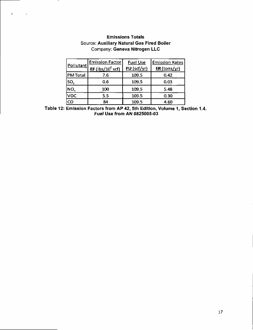
Emissions TotalsSource: Auxiliary Natural Gas Fired Boiler
Company: Geneva Nitrogen LLC
PollutantEmission Factor Fuel Use Emission RatesEF (lbs/106 scf) FU (scf/yr) ER (tons/vr)
PM Total 7.6 109.5 0.42
sox 0.6 109.5 0.03
NOx 100 109.5 5.48
VOC 5.5 109.5 0.30CO 84 109.5 4.60
Table 12: Emission Factors from AP 42, 5th Edition, Volume 1, Section 1.4.Fuel Use from AN 0825005-03
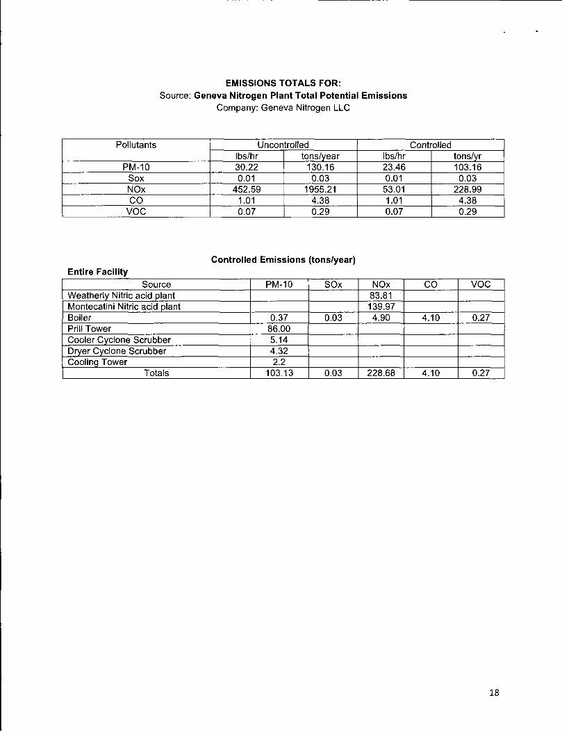
EMISSIONS TOTALS FOR:Source: Geneva Nitrogen Plant Total Potential Emissions
Company: Geneva Nitrogen LLC
Pollutants Uncontrolled ControlledIbs/hr tons/year Ibs/hr tons/yr
PM-10 30.22 130.16 23.46 103.16Sox 0.01 0.03 0.01 0.03NOx 452.59 1955.21 53.01 228.99CO 1.01 4.38 1.01 4.38
VOC 0.07 0.29 0.07 0.29
Controlled Emissions (tons/year)Entire Facility
Source PM-10 SOx NOx CO VOCWeatherly Nitric acid plant 83.81Montecatini Nitric acid plant 139.97Boiler 0.37 0.03 4.90 4.10 0.27Prill Tower 86.00Cooler Cyclone Scrubber 5.14Dryer Cyclone Scrubber 4.32Cooling Tower 2.2
Totals 103.13 0.03 228.68 4.10 0.27
18

Insignificant Emissions Within Sources
The following emission sources are insignificant because they emit less than one ton per year per pollutants of PM10, NOx, S02, CO, or VOCs and the combined emissions of similar small emissions units are less than 5 tons per year (R307-15-5(5)(b)(ii)).
Nitric Acid Manufacturing Process:1. Hydrogen Gas:
Hydrogen gas is used during start-up of the nitric acid facilities. It is used as an ignition source for the catalytic reaction and is only needed for a short period of time (5-10 minutes) and is considered to have insignificant emissions.
2. Ammonia Fugitive Emissions:Small amounts of fugitive emissions from ammonia handling equipment is considered insignificant.
Ammonium Nitrate Solution Manufacturing Process:1. AN Solution Evaporator:
A steam ejector is used to induce a vacuum on the evaporation process. This steam is released to the atmosphere with insignificant amounts of ammonium nitrate particulates.
Ammonium Nitrate Solid Manufacturing Process:1. Processing & Storage Buildings:
Insignificant quantities of ammonium nitrate particulate emissions through open doors and building vents.
2. Loading Operations:Insignificant quantities of ammonium nitrate particulate emissions resulting from bulk loading operations.
Natural Gas Fired Boiler:1. Natural Gas Emergency Relief Valve:
a. Insignificant emissions unless there is an emergency breakdown.
19

Cooling Tower:1. Sodium Hypochlorite Storage:
Sodium hypochlorite is used for algae control in cooling water. Emissions are considered insignificant.
2. Sulfuric Acid Storage:Sulfuric acid is used for pH control of cooling water and plant effluent. Emissions are considered insignificant.
3. Sodium Hydroxide:Sodium hydroxide is used for pH control of cooling water. Emissions are considered insignificant.
4. Cooling Water Chemical Treatment:Storage tanks for cooling water chemical treatments are considered to have insignificant emissions.
5. Cooling Tower Evaporative Emissions:The cooling tower evaporative emissions are considered to be insignificant.
20

Listing and Description of Best Available Control Technologies:
Nitric Acid Plant NOx Abatement Options:1. Selective Catalytic Reduction (SCR):
a. Installation of a SCR catalyst designed to convert oxides of nitrogen (NOx) contained in the plant’s tail gas stream into nitrogen (N) and water (H20). This is accomplished by introducing a reducing agent, in this case anhydrous ammonia (NH3), into the tail gas just upstream of the catalytic reactor. The ammonia and nitrogen oxides interact and complete a reaction in the presence of the abatement catalyst, which converts the nitric oxides into nitrogen and water.
2. Non-Selective Catalytic Reduction (NSCR):a. The non-selective catalytic reduction (NSCR) abatement system utilizes a catalyst to
promote the reaction between a fuel (natural gas) and the oxygen in the tail gas stream. Once the oxygen is removed, the fuel then removes NOx components from the tail gas stream.
3. Absorber Feedwater / Absorber Cooling Water Chilling:a. NOx gas absorption efficiency is enhanced through contact with chilled absorber
feedwater. Enhanced absorption of NOx gas reduces the amount of NOx compounds carried over in tail gas exiting the column. Absorber feedwater can be chilled prior to it’s introduction into an absorption column or by chilling the column’s cooling water supply, which flows through cooling coils embedded in the column’s bubble cap trays.
4. Extended Absorption:a. The extended absorption method for abatement requires an increase in the volume
and surface area available for absorption. By increasing the available area for absorption, the NOx compounds are absorbed and recovered as nitric acid. The volume required for extended absorption can be reduced by using mechanical refrigeration to provide lower absorption temperatures (see item 3 above).
Nitric Acid Plant Technically Feasible / Infeasible NOx Abatement Options:1. Selective Catalytic Reduction (SCR):
a. NOx concentration in the tail gas stream is continually analyzed upstream of the abatement reactor and at the plant’s exhaust stack to determine / ensure removal efficiency. Ammonia injection into the tail gas stream is a controlled function based upon the permitted NOx output at the stack.Geneva Nitrogen believes that the SCR system currently in use for NOx abatement is the best available control technology for this process.
2. Non-Selective Catalytic Reduction (NSCR):a. NSCR abatement technology is not considered BACT in today’s nitric acid industry.
The system has a substantial operating cost and requires the catalyst to be changed every 2-3 years. In addition, in order for the NSCR to reduce NOx, the hydrocarbon fuel must be fed to the system with a 5% stoichiometric excess. This excess causes increased emissions to the atmosphere of unburned hydrocarbons, carbon monoxide, and carbon dioxide.
21

3. Absorber Feedwater / Absorber Cooling Water Chilling:a. This reduces NOx carryover into the plant’s tail gas stream, resulting in a reduction of
NOx compounds into the SCR. Geneva Nitrogen began chilling absorber feedwater in 1997 and improved the absorber feedwater chilling system in 2012.
4. Extended Absorption:a. The absorption technology in the NAP1 Montecatini acid plant is a unique cascade
design that operates at medium pressure (40-45 psig). Because of these lower operating pressures and unique internal design, adding absorption volume to this acid plant has proven to be impossible through trial and extensive process modeling.
b. There are two options available to extend absorption in the NAP2 Weatherly acid plant. The first option would be to replace the existing column with a much larger version (effectively doubling the volume of the column), specifically designed and fabricated for extended absorption. The second option requires the purchase of an additional column (similar size, less trays) to install in series with the existing column. Both options are cost prohibitive.
Rank Options by Control and Cost Effectiveness
Table 13 - NOx Abatement Control Technologies, Extended Absorption
Name of Control TechnologyAnnualized Cost of Control Option
in Dollars
Amount of NOx Pollutant Being Controlled (tpy)
Cost per Ton ($/ton)
Implementation Date (year)
SCR $ 224,032.80 578 $ 387.60 1999 & 2005
NSCR $ 1,716,410.10 584 $ 2,939.06 N/AExtended Absorption (new) $ 266,666.00 162 $ 1,646.09 N/A
Extended Absorption (additional) $ 166,666.00 162 $ 1,028.80 N/A
1. NSCR removal efficiency taken to be 1% greater than SCR (EPA-450/3-91-026)2. NAP2 Weatherly acid plant available for extended absorption only.3. Extended absorption ppm value at the column discharge prior to NOx abatement.
22
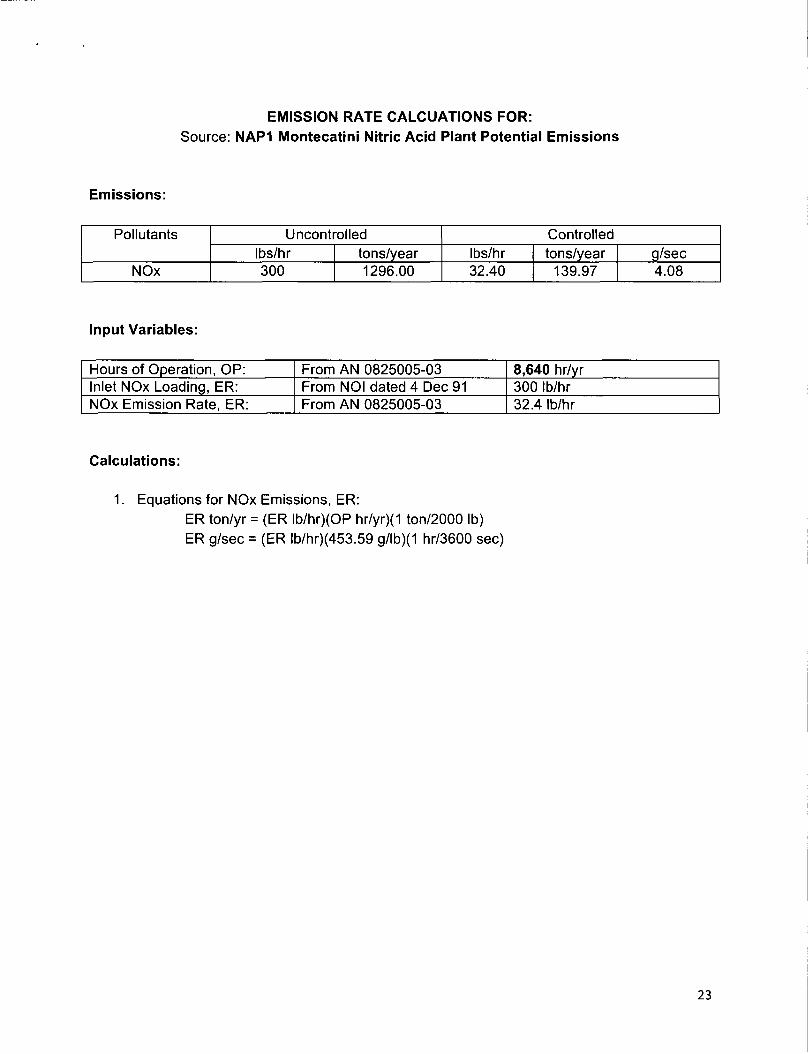
EMISSION RATE CALCUATIONS FOR:Source: NAP1 Montecatini Nitric Acid Plant Potential Emissions
Emissions:
Pollutants Uncontrolled ControlledIbs/hr tons/year Ibs/hr tons/year g/sec
NOx 300 1296.00 32.40 139.97 4.08
Input Variables:
Hours of Operation, OP: From AN 0825005-03 8,640 hr/yrInlet NOx Loading, ER: From NOI dated 4 Dec 91 300 Ib/hrNOx Emission Rate, ER: From AN 0825005-03 32.4 Ib/hr
Calculations:
1. Equations for NOx Emissions, ER:ER ton/yr = (ER lb/hr)(OP hr/yr)(1 ton/2000 lb)ER g/sec = (ER lb/hr)(453.59 g/lb)(1 hr/3600 sec)
23
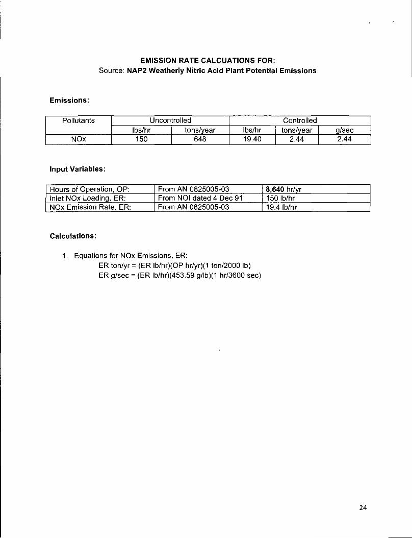
EMISSION RATE CALCUATIONS FOR:Source: NAP2 Weatherly Nitric Acid Plant Potential Emissions
Emissions:
Pollutants Uncontrolled ControlledIbs/hr tons/year Ibs/hr tons/year g/sec
NOx 150 648 19.40 2.44 2.44
Input Variables:
Hours of Operation, OP: From AN 0825005-03 8,640 hr/yrInlet NOx Loading, ER: From NOI dated 4 Dec 91 150 Ib/hrNOx Emission Rate, ER: From AN 0825005-03 19.4 Ib/hr
Calculations:
1. Equations for NOx Emissions, ER:ER ton/yr = (ER lb/hr)(OP hr/yr)(1 ton/2000 lb)ER g/sec = (ER lb/hr)(453.59 g/lb)(1 hr/3600 sec)
24

Ammonium Nitrate Plant PM 10/2.5 Abatement Options:1. PM10/2.5 Emissions, Wet Scrubbing:
a. AN Solids - Wet Scrubber System:The ammonium nitrate solidification process uses rotary drums for drying and cooling the solids (prill). These drums require counter-current air that entrains ammonium nitrate dust (fines). These fines are removed from the air stream before being emitted to the atmosphere by using a wet scrubbing system. The scrubbers force the air into a cyclonic motion which forces the heavier ammonium nitrate fines to collect on the outer surfaces of the scrubber. The scrubber is continually washed with water to collect and dissolve these fines from the surface of the scrubber.
Geneva Nitrogen has operated wet scrubbers to remove prilling train particulate since 1957. This technology is not considered highly efficient, but has been effective enough to influence the State of Utah to discontinue required scrubber stack testing in 2003.
b. Prill Tower:The prill tower emissions of PM 10 and PM2.5 are currently uncontrolled, but historically Geneva Nitrogen operates significantly below it’s permit limit.
2. PM10/2.5 Emissions, Mist Eliminator Candles:a. AN Solids - Wet Scrubbing & Mist Eliminators:
The currently installed air scrubbers would be used in series with mist elimination (Brinks) candles, a Monsanto Chemical design. These mist eliminator candles are designed to capture / remove ultra-fine particulate matter in the scrubber exhaust stream. The scrubber exhaust would be ducted into a module containing the mist eliminators, the clean air exhausting through an induced draft fan and stack located at the module discharge.
b. Prill Tower - Mist Eliminators:The prill tower exhaust would be ducted to ground level and pulled through a module containing mist elimination (Brinks) candles, a Monsanto Chemical design. These mist eliminator candles are designed to capture / remove ultra-fine particulate matter in the prill tower exhaust stream. The clean air would exhaust through an induced draft fan and stack located at the module discharge.
25
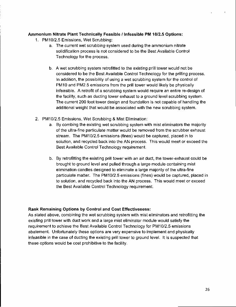
Ammonium Nitrate Plant Technically Feasible / Infeasible PM 10/2.5 Options:1. PM10/2.5 Emissions, Wet Scrubbing:
a. The current wet scrubbing system used during the ammonium nitrate solidification process is not considered to be the Best Available Control Technology for the process.
b. A wet scrubbing system retrofitted to the existing prill tower would not be considered to be the Best Available Control Technology for the prilling process.In addition, the possibility of using a wet scrubbing system for the control of PM10 and PM2.5 emissions from the prill tower would likely be physically infeasible. A retrofit of a scrubbing system would require an entire re-design of the facility, such as ducting tower exhaust to a ground level scrubbing system. The current 200 foot tower design and foundation is not capable of handling the additional weight that would be associated with the new scrubbing system.
2. PM10/2.5 Emissions, Wet Scrubbing & Mist Elimination:a. By combing the existing wet scrubbing system with mist eliminators the majority
of the ultra-fine particulate matter would be removed from the scrubber exhaust stream. The PM10/2.5 emissions (fines) would be captured, placed in to solution, and recycled back into the AN process. This would meet or exceed the Best Available Control Technology requirement.
b. By retrofitting the existing prill tower with an air duct, the tower-exhaust could be brought to ground level and pulled through a large module containing mist elimination candles designed to eliminate a large majority of the ultra-fine particulate matter. The PM 10/2.5 emissions (fines) would be captured, placed in to solution, and recycled back into the AN process. This would meet or exceed the Best Available Control Technology requirement.
Rank Remaining Options by Control and Cost Effectiveness:As stated above, combining the wet scrubbing system with mist eliminators and retrofitting the existing prill tower with duct work and a large mist eliminator module would satisfy the requirement to achieve the Best Available Control Technology for PM10/2.5 emissions abatement. Unfortunately these options are very expensive to implement and physically infeasible in the case of ducting the existing prill tower to ground level. It is suspected that these options would be cost prohibitive to the facility.
26

Rank Options by Control and Cost Effectiveness
Table 14 - PM 10/2.5 Abatement Control Technologies
Name of Control
Technology
Annualized Costof Control
Option in Dollars
Amount of
NOxPollutant Being Controlled (tpy)
Cost per Ton (S/ton)
Implementation
Date (year)
Prill Tower (None) N/A 86 #VALUE! 1957Prill Tower (Mist Eliminator) $ 666,666.67 86 $ 7,751.94 N/A
Predryer (Wet Scrubber) N/A 13.05 #VALUE! 1957Predryer (Scrubber & Mist Elim) $ 17,000.00 13.05 $ 1,302.68 N/A
Dryer (Wet Scrubber) N/A 15.34 #VALUE! 1957Dryer (Scrubber & Mist Elim) $ 17,000.00 15.34 $ 1,108.21 N/A
Cooler (Wet Scrubber) N/A 15.38 #VALU E! 1957Cooler (Scrubber & Mist Elim) $ 17,000.00 15.38 $ 1,105.33 N/A
*The mist eliminator technology is a design utilized by El Dorado Chemical in Arkansas and is considered within the ammonium nitrate industry as the best available control technology for prill tower / scrubber PM2.5 removal. The module estimate Geneva Nitrogen obtained would combine both prill tower and 3 cyclone scrubber exhaust stacks into a single PM2.5 removal system with a common exhaust. The collection efficiency of all particles greater than 1 micron will approach 100% while collection efficiency of all particles less than 1 micron will approach 98%.
27
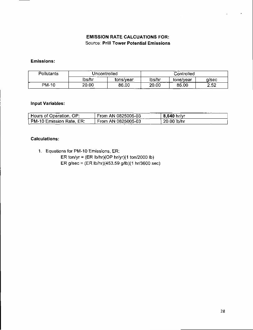
EMISSION RATE CALCUATIONS FOR:Source: Prill Tower Potential Emissions
Emissions:
Pollutants Uncontrolled ControlledIbs/hr tons/year Ibs/hr tons/year g/sec
PM-10 20.00 86.00 20.00 86.00 2.52
Input Variables:
Hours of Operation, OP: From AN 0825005-03 8,640 hr/yrPM-10 Emission Rate, ER: From AN 0825005-03 20.00 Ib/hr
Calculations:
1. Equations for PM-10 Emissions, ER:ER ton/yr = (ER lb/hr)(OP hr/yr)(1 ton/2000 lb)ER g/sec = (ER lb/hr)(453.59 g/lb)(1 hr/3600 sec)
28

EMISSION RATE CALCUATIONS FOR:Source: Pre Dryer Cyclone Scrubber Potential Emissions
Emissions:
Pollutants Uncontrolled ControlledIbs/hr tons/year Ibs/hr tons/year g/sec
PM-10 3.02 13.05 1.00 4.32 0.13
Input Variables:
Hours of Operation, OP: From AN 0825005-03 8,640 hr/yrInlet PM-10 Loading, ER: From Sep 90 Stack Test 3.02 Ib/hrPM-10 Emission Rate, ER: From AN 0825005-03 1.00 Ib/hr
Calculations:
1. Equations for PM-10 Emissions, ER:ER ton/yr = (ER lb/hr)(OP hr/yr)(1 ton/2000 lb)ER g/sec = (ER lb/hr)(453.59 g/lb)(1 hr/3600 sec)
29

EMISSION RATE CALCUATIONS FOR:Source: Dryer Cyclone Scrubber Potential Emissions
Emissions:
Pollutants Uncontrolled ControlledIbs/hr tons/year Ibs/hr tons/year g/sec
PM-10 3.55 15.34 1.18 5.10 0.15
Input Variables:
Hours of Operation, OP: From AN 0825005-03 8,640 hr/yrInlet PM-10 Loading, ER: From Sep 90 Stack Test 3.55 Ib/hrPM-10 Emission Rate, ER: From AN 0825005-03 1.18 Ib/hr
Calculations:
1. Equations for PM-10 Emissions, ER:ER ton/yr = (ER lb/hr)(OP hr/yr)(1 ton/2000 lb)ER g/sec = (ER lb/hr)(453.59 g/lb)(1 hr/3600 sec)
30

EMISSION RATE CALCUATIONS FOR:Source. Cooler Cyclone Scrubber Potential Emissions
Emissions:
Pollutants Uncontrolled ControlledIbs/hr tons/year Ibs/hr tons/year g/sec
PM-10 3.56 15.38 1.19 5.14 0.15
Input Variables:
Hours of Operation, OP: From AN 0825005-03 8,640 hr/yrInlet PM-10 Loading, ER: From Sep 90 Stack Test 3.56 Ib/hrPM-10 Emission Rate, ER: From AN 0825005-03 1.19 Ib/hr
Calculations:
1. Equations for PM-10 Emissions, ER:ER ton/yr = (ER lb/hr)(OP hr/yr)(1 ton/2000 lb)ER g/sec = (ER lb/hr)(453.59 g/lb)(1 hr/3600 sec)
31
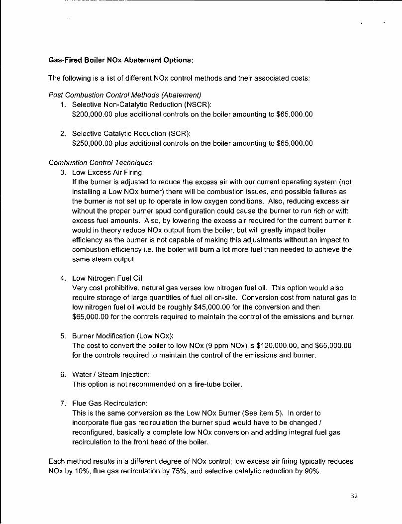
The following is a list of different NOx control methods and their associated costs:
Post Combustion Control Methods (Abatement)1. Selective Non-Catalytic Reduction (NSCR):
$200,000.00 plus additional controls on the boiler amounting to $65,000.00
2. Selective Catalytic Reduction (SCR):$250,000.00 plus additional controls on the boiler amounting to $65,000.00
Combustion Control Techniques3. Low Excess Air Firing:
If the burner is adjusted to reduce the excess air with our current operating system (not installing a Low NOx burner) there will be combustion issues, and possible failures as the burner is not set up to operate in low oxygen conditions. Also, reducing excess air without the proper burner spud configuration could cause the burner to run rich or with excess fuel amounts. Also, by lowering the excess air required for the current burner it would in theory reduce NOx output from the boiler, but will greatly impact boiler efficiency as the burner is not capable of making this adjustments without an impact to combustion efficiency i.e. the boiler will burn a lot more fuel than needed to achieve the same steam output.
4. Low Nitrogen Fuel Oil:Very cost prohibitive, natural gas verses low nitrogen fuel oil. This option would also require storage of large quantities of fuel oil on-site. Conversion cost from natural gas to low nitrogen fuel oil would be roughly $45,000.00 for the conversion and then $65,000.00 for the controls required to maintain the control of the emissions and burner.
5. Burner Modification (Low NOx):The cost to convert the boiler to low NOx (9 ppm NOx) is $120,000.00, and $65,000.00 for the controls required to maintain the control of the emissions and burner.
6. Water / Steam Injection:This option is not recommended on a fire-tube boiler.
7. Flue Gas Recirculation:This is the same conversion as the Low NOx Burner (See item 5). In order to incorporate flue gas recirculation the burner spud would have to be changed / reconfigured, basically a complete low NOx conversion and adding integral fuel gas recirculation to the front head of the boiler.
Each method results in a different degree of NOx control; low excess air firing typically reduces NOx by 10%, flue gas recirculation by 75%, and selective catalytic reduction by 90%.
Gas-Fired Boiler NOx Abatement Options:
32
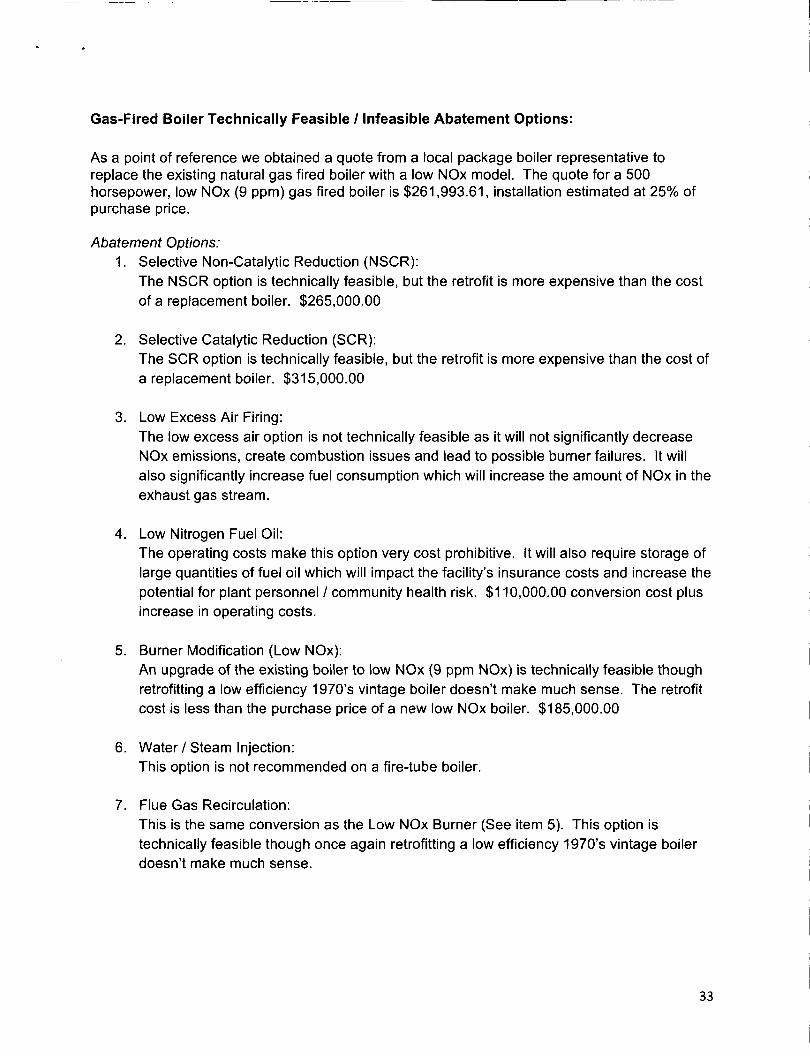
Gas-Fired Boiler Technically Feasible / Infeasible Abatement Options:
As a point of reference we obtained a quote from a local package boiler representative to replace the existing natural gas fired boiler with a low NOx model. The quote for a 500 horsepower, low NOx (9 ppm) gas fired boiler is $261,993.61, installation estimated at 25% of purchase price.
Abatement Options:1. Selective Non-Catalytic Reduction (NSCR):
The NSCR option is technically feasible, but the retrofit is more expensive than the cost of a replacement boiler. $265,000.00
2. Selective Catalytic Reduction (SCR):The SCR option is technically feasible, but the retrofit is more expensive than the cost of a replacement boiler. $315,000.00
3. Low Excess Air Firing:The low excess air option is not technically feasible as it will not significantly decrease NOx emissions, create combustion issues and lead to possible burner failures. It will also significantly increase fuel consumption which will increase the amount of NOx in the exhaust gas stream.
4. Low Nitrogen Fuel Oil:The operating costs make this option very cost prohibitive. It will also require storage of large quantities of fuel oil which will impact the facility’s insurance costs and increase the potential for plant personnel / community health risk. $110,000.00 conversion cost plus increase in operating costs.
5. Burner Modification (Low NOx):An upgrade of the existing boiler to low NOx (9 ppm NOx) is technically feasible though retrofitting a low efficiency 1970’s vintage boiler doesn’t make much sense. The retrofit cost is less than the purchase price of a new low NOx boiler. $185,000.00
6. Water/Steam Injection:This option is not recommended on a fire-tube boiler.
7. Flue Gas Recirculation:This is the same conversion as the Low NOx Burner (See item 5). This option is technically feasible though once again retrofitting a low efficiency 1970’s vintage boiler doesn’t make much sense.
33
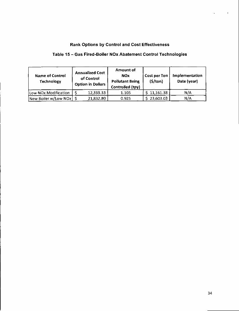
Rank Options by Control and Cost Effectiveness
Table 15 - Gas Fired-Boiler NOx Abatement Control Technologies
Name of Control Technology
Annualized Costof Control
Option in Dollars
Amount of
NOxPollutant Being Controlled (tpy)
Cost per Ton ($/ton)
Implementation Date (year)
Low NOx Modification $ 12,333.33 1.105 $ 11,161.38 N/A
New Boiler w/Low NOx $ 21,832.80 0.925 $ 23,603.03 N/A
34

EMISSION RATE CALCUATIONS FOR:Source: Natural Gas Fired Package Boiler Potential Emissions
Emissions:
Pollutants Uncontrolled ControlledIbs/hr tons/year Ibs/hr tons/year g/sec
NOx 2.78 12.183 N/A N/A N/APM 10 Filterable 0.044 0.195 N/A N/A N/A
PM 10 Condensable 0.133 0.584 N/A N/A N/APM 2.5 Filterable 0.044 0.195 N/A N/A N/A
PM 2.5 Condensable 0.133 0.584N/A
N/A N/A
‘Assumes boiler operating at full rate, 100 ppm anticipated exhaust emissions
Input Variables:
Hours of Operation, OP: N/A 8,760 hr/yr - manufacturers’ tableInlet NOx Loading, ER: N/A N/A (* See below)NOx Emission Rate, ER: From AN 0825005-03 N/A (* See below)
* Natural Gas Fired Boiler Permit Limit: 109.5 million standard cubic feet of natural gas consumption limit by package steam boiler in a 12-month period.
Calculations:
ER ton/yr = (ER lb/hr)(OP hr/yr)(1 ton/2000 lb)ER g/sec = (ER lb/hr)(453.59 g/lb)(1 hr/3600 sec)
1. Equations for NOx Emissions, ER:Emissions values gathered from boiler manufactures’ data tables.
35
Cooling Tower PM 10/2.5 Abatement Options:
The following is a list of different PM 10/2.5 control methods for cooling towers:
1. Cooling tower retrofitted with high efficiency drift eliminators.
2. Make-up water supply utilizing high quality well water to eliminate treatment chemicals generally associated with municipal provided potable water.
3. Install a continuous flow side-stream filtration system (packed-bed sand filter) to remove silt and suspended solids.
4. Support real time monitoring and control of cooling tower dissolved and suspended solids loading (conductivity). Automate cooling tower blowdown (and subsequently cooling tower make-up) based on tower conductivity.
5. Automate cooling water chemical feed systems which meter treatment chemicals based on both real-time chemical monitoring (analyzers) and employ a highly experienced water treatment vendor to monitor / manipulate the treatment program.
Cooling Tower PM 10/2.5 Technically Feasible / Infeasible NOx Abatement Options:
1. Cooling Tower Drift Eliminators:a. Geneva Nitrogen operates a cooling tower which was retrofit with high efficiency drift
eliminators in the 1980’s. The tower fill has been replaced periodically, on an as- needed basis.
2. Cooling Tower Make-up Water Supply:a. Geneva Nitrogen owns / operates a deep aquifer well which supplies make-up water
to the cooling tower. The well water is relatively low in mineral content, averaging 171 mg/I total dissolved solids.
3. Side-Stream Filtration:a. Geneva Nitrogen operates a side-stream packed-bed sandfilter which operates 8640
hours per year. It has been in operation since 1994.4. Real-Time Cooling Water Conductivity Measurement and Automated Blowdown:
a. Geneva Nitrogen measures cooling water conductivity in real-time and maintains tower conductivity by means of automated continuous blowdown.
5. Automated Chemical Feed System:a. Geneva Nitrogen maintains an automated cooling water chemical feed system. GN
employs a water treatment vendor (Nalco) to verify water quality and make corrective adjustments to the feed system controls.
36

Appendix Section
Appendix A
37
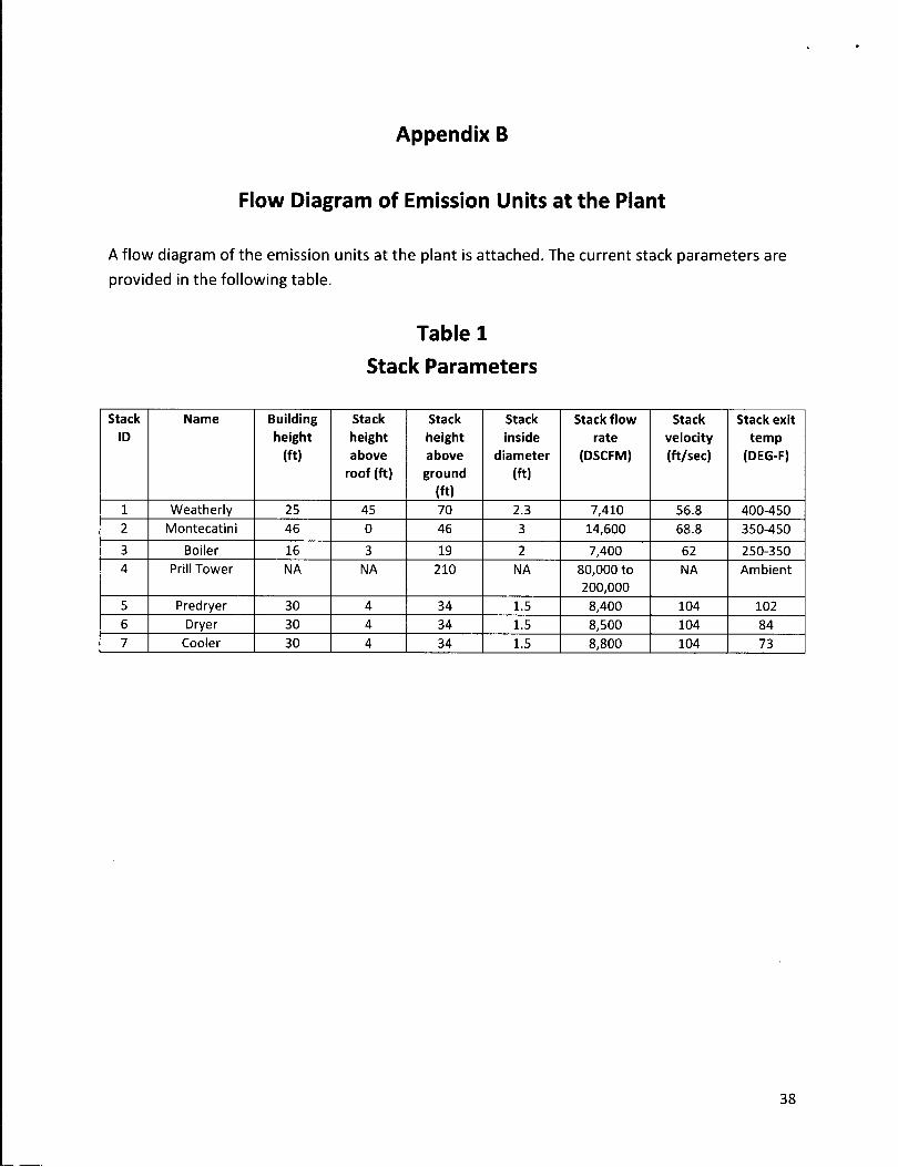
Appendix B
Flow Diagram of Emission Units at the Riant
A flow diagram of the emission units at the plant is attached. The current stack parameters are
provided in the following table.
Table 1
Stack Parameters
Stack
ID
Name Building
height
(ft)
Stack
height
above
roof (ft)
Stack
height
above
ground(ft)
Stack
inside
diameter
(ft)
Stack flow
rate(DSCFM)
Stack
velocity
(ft/sec)
Stack exit
temp (DEG-F)
1 Weatherly 25 45 70 2.3 7,410 56.8 400-4502 Montecatini 46 0 46 3 14,600 68.8 350-450
3 Boiler 16 3 19 2 7,400 62 250-3504 Prill Tower NA NA 210 NA 80.000 to
200.000NA Ambient
5 Predryer 30 4 34 1.5 8,400 104 1026 Dryer 30 4 34 1.5 8,500 104 847 Cooler 30 4 34 1.5 8,800 104 73
38
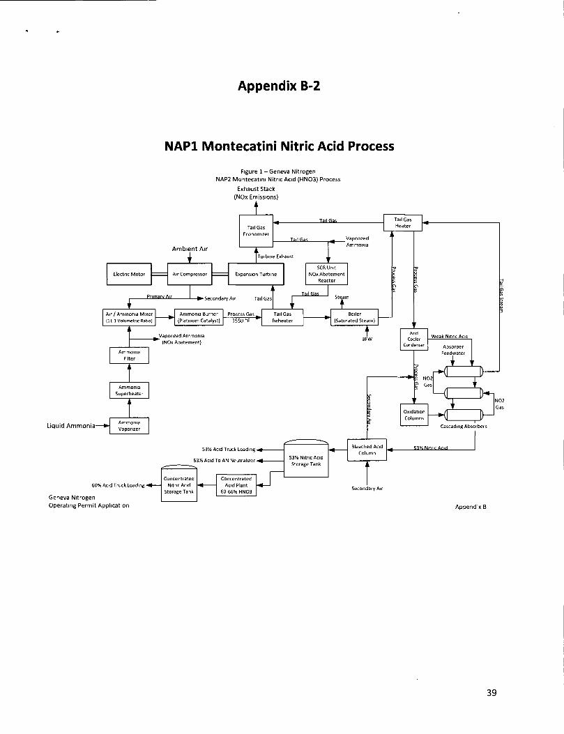
Appendix B-2
NAP1 Montecatini Nitric Acid Process
Figure 1 - Geneva NitrogenNAP2 Montecatini Nitric Acid (HN03) Process
Exhaust Stack (NOx Emissions)
Operating Permit Application Appendix B
39
Tail S
as Stream

Appendix B-3
NAP2 Weatherly Nitric Acid Process
Figure 2 - Geneva Nitrogen NAP2 Weatherly Nitric Acid (HN03) Process
Exhaust Stack
Operating Permit Application Appendix B
40

Appendix B-4
Steam-
Steam
Ammonium Nitrate Solution Process
Figure 3 - Geneva Nitrogen Ammonium Nitrate Solution Process
Geneva Nitrogen Operating Permit Application Appendix B

Appendix B-5
SapphyrInternalAdditive
Ammonium Nitrate Prilling Process
Figure 4 - Geneva Nitrogen Ammonium Nitrate Prill (NH4N03) Process
Emission to AtmosphereFugitive Emission to Atmosphere
(NH4N03)
Emission to Atmosphere (NH4N03 & NH3)
Emission to Atmosphere (NH4N03 & NH3)
Emission to Atmosphere (NH4N03 & NH3)
Geneva Nitrogen Operating Permit Application Appendix B