dk english manual · keyer and plug all connectors from the cable set to the appropriate jacks at...
TRANSCRIPT

micro HAM © 2010 All rights reserved
DigiKeyermicro HAM
fax: +421 2 4594 5100e-mail: [email protected]: www.microham.com
Version 7.55 December, 2010
1

micro HAM © 2010 All rights reserved
TABLE OF CONTENTS
CHAPTER PAGE
1. FEATURES AND FUNCTIONS ........................................................................................................ 32. IMPORTANT WARNINGS ................................................................................................................ 33. PANEL DESCRIPTION .................................................................................................................... 4
Front Panel .......................................................................................................................... 4Rear Panel .......................................................................................................................... 5
4. INSTALLATION ................................................................................................................................ 6Preparing for Use................................................................................................................. 6Macintosh (OS-X) Installation .............................................................................................. 7Windows (Windows 2000, XP, Vista & Windows 7) Installation .......................................... 7
Installing microHAM USB Device Router ......................................................................7Configuring USB Audio Codec ........................................................................8Configuring microHAM USB Device Router ................................................................ 9Creating and Using Virtual Ports ................................................................................ 10
5. micro HAM DEVICE ROUTER ........................................................................................................ 11Menu: Router ..................................................................................................................... 11Menu: Preset ..................................................................................................................... 12Menu: Device ..................................................................................................................... 13Menu: Virtual Port .............................................................................................................. 14Menu: Help ........................................................................................................................ 15Device Configuration .......................................................................................................... 15
Ports Tab..................................................................................................................... 16CAT& 2nd CAT ...................................................................................................... 17FSK & 2nd FSK .................................................................................................... 20CW ....................................................................................................................... 21PTT & 2nd PTT ..................................................................................................... 22Squelch ................................................................................................................ 22Control...................................................................................................................22
Keying Tab.................................................................................................................. 23Audio .................................................................................................................... 23PTT........................................................................................................................24
FSK from Keyboard .....................................................................................................24FSK Messages ............................................................................................................25
6. EXTERNAL KEYBOARD ................................................................................................................ 267. PACKAGE CONTENTS .................................................................................................................. 268. WARRANTY ................................................................................................................................... 279. SPECIFICATIONS .......................................................................................................................... 27
10. SYSTEM CONSIDERATIONS ........................................................................................................ 2811. HARDWARE SPECIFICATIONS .................................................................................................... 28
DECLARATION OF CONFORMITY ......................................................................................... 29
APPENDIX A – CONNECTORS ............................................................................................... 30
APPENDIX B – RFI Considerations ........................................................................................... 31
APPENDIX C – Tracking ........................................................................................................... 32
2
micro HAM © 2010 All rights reserved
1 - FEATURES AND FUNCTIONS
� No Serial or Parallel port necessary, just one USB port � Complete "Computer <-> Radio" isolation
• bidirectional transformer isolation of audio signals• optical isolation of ALL digital signals: Radio Control, CW, PTT, FSK
� Internal USB sound capability • Wide range audio level: works with transceiver levels from 100 mV to 1.5 V• Extremely low noise floor: as low as 0.7 mV effective • High dynamic range: 84 dB typical, 82 dB minimum
� Compatible with all MS Windows based logging or con trol software• the special microHAM "USB Device Router" program creates virtual COM ports for full operation with
standard Windows applications. • customizable presets allow instantly changing DIGI KEYER parameters to match the program
currently in use � Integrated computer control port for all radios CI- V, FIF-232, IF-232, RS-232
• fully supports Icom, Kenwood, TenTec, Yaesu and other radios• no separate level converter required
� Squelch input for additional software control� Strong RFI immunity
• integrated chokes and filters for best RFI immunity• advanced shielding and circuit design for RFI product suppression
� Connections: • Computer – USB• Radio - DB15
� Front panel LEDs for easy visual feedback of CW, PT T, SQL, POWER and radio control data� Front panel adjustable Transmit and Receive audio l evels� USB sound support built-in to the Operating System
• does not require special drivers or limit your choice of applications.• Supported under Windows, Apple OS 10 and LINUX
� Metal/Aluminum case, powder coated and silk screene d � Free, no time limit, on-line firmware/software upgr ades
2 - IMPORTANT WARNINGS
You must set the CAT level jumpers inside the DIGI KEYER before using it for the first time.
If you power DigiKeyer from an external power suppl y ALWAYS check the polarity of the external 13.8 V supply.
If your radio includes upgradeable firmware, DO NOT perform any upgrade through DigiKeyer.
3
micro HAM © 2010 All rights reserved
3 - PANEL DESCRIPTION
FRONT PANEL
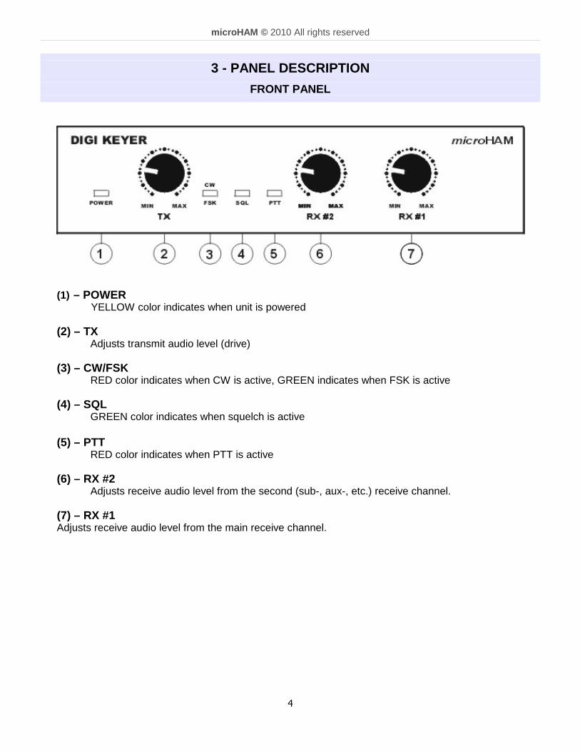
(1) – POWER YELLOW color indicates when unit is powered
(2) – TX
Adjusts transmit audio level (drive) (3) – CW/FSK
RED color indicates when CW is active, GREEN indicates when FSK is active (4) – SQL GREEN color indicates when squelch is active
(5) – PTT RED color indicates when PTT is active
(6) – RX #2 Adjusts receive audio level from the second (sub-, aux-, etc.) receive channel.
(7) – RX #1 Adjusts receive audio level from the main receive channel.
4

micro HAM © 2010 All rights reserved
REAR PANEL
All connectors for connecting the computer, radio and accessories are located on the rear panel.
(1) – PA PTT: PTT output for Power Amplifier Ground during transmit TIP - SignalSHELL - Ground
(2) - LNA PTT: Control output for Low Noise Amplifier Ground during transmit TIP - SignalSHELL - Ground
If the jumper is in SS position, open collector switchingtransistor is connected to the PAPTT or LNAPTT output jack.
The transistor can switch up to 48V @ .8A. This position isappropriate for modern Power Amplifiers with electronickeying and LNA bypass relays .
Check manual of your PA and LNA to be sure the power requirements do not exceed the transistor ratingotherwise set the appropriate jumper to the RE position. This position connects the relay contact to theoutput jack. Maximum rating for the relay is:48V AC/DC @ 1A.
NOTE: If you are not sure about keying voltage of your amp on LNA, use the RE position.
(3) - RADIO: DB15F connector for radio interconnection – a detailed description is in Appendix A
(4) - REM: MiniDIN6 for PS/2 keyboard or numeric keypad.
(5) - USB: USB B connector for computer connection. Connect the supplied USB A-B cable.
5

micro HAM © 2010 All rights reserved
4 - INSTALLATION
Installing DIGI KEYER consists of several steps: 1) prepare DIGI KEYER to work with your radio2) install microHAM USB Device Router (the control and interface software)
configure the Windows USB Audio Device3) configure Router
Preparing DigiKeyer for Use
1. Remove the top cover from the DIGI KEYER and set the CAT jumpers as shown in the following chart. TheCAT interface jumpers must be configured to select the proper level for each radio type.
RS-232 levels: Elecraft: K2, K3, Icom: 7800, JRC: JST-245, Kenwood: TS-480, 570, 590, 870, 2000, TenTec: all radios with DB9 or DB25 connectorsYaesu: FT-450, FT-847, FT-920, FT-950, FT-1000MP, Mark V, Mark V Field, FT-2000, FT-5000, FT-9000
IF-232 levels:Kenwood: TS-140, 440, 450, 680, 690, 711, 790, 811,850, 940, 950
FIF-232 levels: Yaesu: FT-100, 736, 747, 757GXII, 767, 817, 840,857, 890, 897, 900, 980, 990, 1000, 1000D
CI-V levels: Icom: all radios except 7700 & 7800 with RS-232 TenTec: all radios with 3.2 mm connector
NOTE: the CAT interface is not configured at the factory.
2. Plug the DB15M on the radio cable set into the DB15 connector on the rear panel of the DIGIKEYER and plug ALL connectors from the cable set to the appropriate jacks at the rear panel ofyour transceiver. Each connector on the radio interface cable is marked same as the matching jackon your transceiver.
3. If the radio cable ends with leads for external power, connect these leads to a 12-16V DC powersupply.
Be sure to observe the proper polarity.
4. Locate but do not connect the USB cable from DigiKeyer to your computer.
NOTE: If you will be installing on a Windows computer, skip to “MICROSOFT WINDOWS(Windows 2000, XP, Vista, & Windows 7) INSTALLATION.”
6
IF232
CI-V
FIF232
RS232
micro HAM © 2010 All rights reserved
Mac OS X INSTALLATION
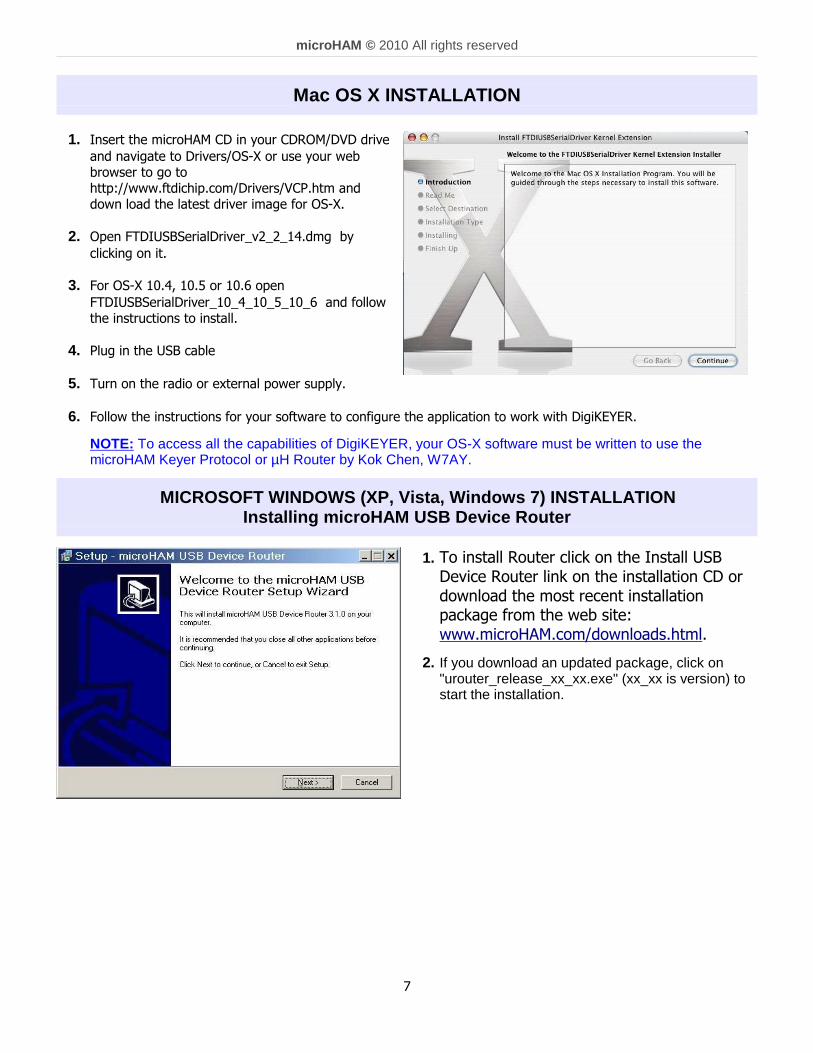
1. Insert the microHAM CD in your CDROM/DVD drive
and navigate to Drivers/OS-X or use your webbrowser to go tohttp://www.ftdichip.com/Drivers/VCP.htm anddown load the latest driver image for OS-X.
2. Open FTDIUSBSerialDriver_v2_2_14.dmg by
clicking on it.
3. For OS-X 10.4, 10.5 or 10.6 open
FTDIUSBSerialDriver_10_4_10_5_10_6 and followthe instructions to install.
4. Plug in the USB cable
5. Turn on the radio or external power supply.
6. Follow the instructions for your software to configure the application to work with DigiKEYER.
NOTE: To access all the capabilities of DigiKEYER, your OS-X software must be written to use themicroHAM Keyer Protocol or µH Router by Kok Chen, W7AY.
MICROSOFT WINDOWS (XP, Vista, Windows 7) INSTALLATI ON
Installing micro HAM USB Device Router
1. To install Router click on the Install USBDevice Router link on the installation CD ordownload the most recent installationpackage from the web site:www.microHAM.com/downloads.html.
2. If you download an updated package, click on"urouter_release_xx_xx.exe" (xx_xx is version) tostart the installation.
7
micro HAM © 2010 All rights reserved
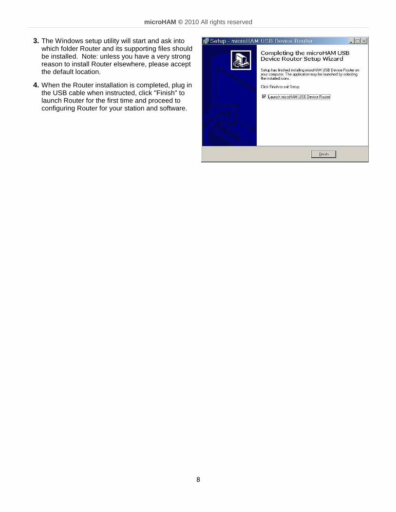
3. The Windows setup utility will start and ask intowhich folder Router and its supporting files shouldbe installed. Note: unless you have a very strongreason to install Router elsewhere, please acceptthe default location.
4. When the Router installation is completed, plug inthe USB cable when instructed, click "Finish" tolaunch Router for the first time and proceed toconfiguring Router for your station and software.
8
micro HAM © 2010 All rights reserved
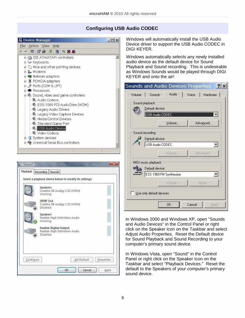
Configuring USB Audio CODEC
Windows will automatically install the USB AudioDevice driver to support the USB Audio CODEC inDIGI KEYER.
Windows automatically selects any newly installedaudio device as the default device for SoundPlayback and Sound recording. This is undesirableas Windows Sounds would be played through DIGIKEYER and onto the air!
In Windows 2000 and Windows XP, open "Soundsand Audio Devices" in the Control Panel or rightclick on the Speaker icon on the Taskbar and selectAdjust Audio Properties. Reset the Default devicefor Sound Playback and Sound Recording to yourcomputer's primary sound device.
In Windows Vista, open "Sound" in the ControlPanel or right click on the Speaker Icon on theTaskbar and select "Playback Devices." Reset thedefault to the Speakers of your computer's primarysound device.
9

micro HAM © 2010 All rights reserved
Configuring micro HAM USB Device Router
The microHAM USB Device Router (Router) program provides a Windows compatible configuration tool formicroHAM USB Devices (DIGI KEYER as well as microKEYER, CW Keyer and USB Interfaces) andsoftware interface to other Windows applications (loggers, digital mode software, etc.). The softwareinterface is provided as Virtual Serial Ports.
To configure and use DIGI KEYER with Windows compatible application programs it is necessary to haveinstalled the USB driver, started the Router, and applied power to DIGI KEYER by turning on the attachedradio or external power supply. Router is then configured to match the requirements of the application(logger or digital mode) software.
DIGI KEYER Status
When the USB driver is installed correctly and DIGI KEYERis powered from a radio or external 12V DC supply Routerwill show a device tab with a GREEN check beside thedevice name (DIGI KEYERI).
When Router shows a YELLOW “X” instead of a green ����,it means the USB driver is correctly installed but DIGIKEYER is not receiving power from the radio or externalsupply.
When Router shows a RED “X” instead of a green ����, itmeans the device is disconnected and Router does not seethe USB part of DIGI KEYER.
This happens when the USB cable is unplugged or the USBdriver is not correctly installed.
Initial Setup
Router must be used to configure DIGI KEYER for properoperation. The device configuration tab (in the redrectangle) is used to setup each part of the DIGI KEYER– virtual ports for communicating with the application(Ports), audio levels, PTT and keyboard FSK (Keying),and stored FSK messages (FSK Messages).
10
micro HAM © 2010 All rights reserved
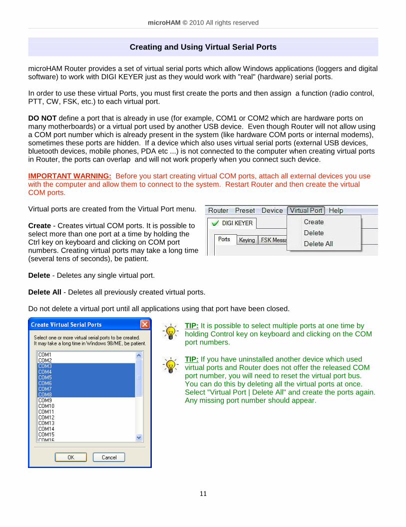
Creating and Using Virtual Serial Ports
microHAM Router provides a set of virtual serial ports which allow Windows applications (loggers and digitalsoftware) to work with DIGI KEYER just as they would work with "real" (hardware) serial ports.
In order to use these virtual Ports, you must first create the ports and then assign a function (radio control,PTT, CW, FSK, etc.) to each virtual port.
DO NOT define a port that is already in use (for example, COM1 or COM2 which are hardware ports onmany motherboards) or a virtual port used by another USB device. Even though Router will not allow usinga COM port number which is already present in the system (like hardware COM ports or internal modems),sometimes these ports are hidden. If a device which also uses virtual serial ports (external USB devices,bluetooth devices, mobile phones, PDA etc ...) is not connected to the computer when creating virtual portsin Router, the ports can overlap and will not work properly when you connect such device.
IMPORTANT WARNING: Before you start creating virtual COM ports, attach all external devices you usewith the computer and allow them to connect to the system. Restart Router and then create the virtualCOM ports.
Virtual ports are created from the Virtual Port menu.
Create - Creates virtual COM ports. It is possible toselect more than one port at a time by holding theCtrl key on keyboard and clicking on COM portnumbers. Creating virtual ports may take a long time(several tens of seconds), be patient.
Delete - Deletes any single virtual port.
Delete All - Deletes all previously created virtual ports.
Do not delete a virtual port until all applications using that port have been closed.
TIP: It is possible to select multiple ports at one time byholding Control key on keyboard and clicking on the COMport numbers.
TIP: If you have uninstalled another device which usedvirtual ports and Router does not offer the released COMport number, you will need to reset the virtual port bus.You can do this by deleting all the virtual ports at once.Select "Virtual Port | Delete All" and create the ports again.Any missing port number should appear.
11
micro HAM © 2010 All rights reserved
5. micro HAM USB DEVICE ROUTERROUTER MENU
Default Router Settings: used to completely reset Router to factory (default) settings. "Default" removes all device tabs and deletes all stored configuration data, including all user presets.from the Windows Registry.
TIP: DigiKEYER can be reset to the factory configuration by selecting Default Router Settingsfollowed by Device | Store as Power-up Settings to save the defaults to the keyer's memory.
Restore Router Settings: used to restore settings from a urs file created by the backup command. A urs file can be used only with the device for which it was generated (the file contains the unit serialnumber) on a computer with same port assignments.
WARNING: Restoring a backup replaces all current Router settings including presets, use it carefully!
Backup Router Settings: used to create backup urs file. This file contains Router settings (including Presets) for all devices defined in Router.
Options | General - Load Router on Start-up: when checked, Router will start automatically each time the computer isstarted or rebooted. - Start Router Minimized: when checked, Router will started minimized
Options | Band Map: - Does not apply to DigiKeyer - Customizable band edge boundaries used to drive the band data output. BCD codes can becustomized for driving antenna switches or bandpass filter control.
Options | Digital Band Map: - Does not apply to DigiKeyer - Customizable band boundaries for the digital mode operation. These settings are used for the (optional)automatic selection of audio switching and PTT mode based on operating frequency. Careful selectionof the "Digital band" is necessary for transceivers which do not have a special mode for AFSK operationor do not report the mode in the computer command set. This primarily effects Kenwood and TenTectransceivers although it applies to some older Icom and Yaesu radios.
Options | Audio Devices: - Don't use audio devices: when checked, Router does not use audio devices and the settings on the
Audio Mixer and DVK tabs have no effect.- Manually assign audio devices: when checked, Router will allow the user to select audio devices
(sound card) in the appropriate fields at Audio Mixer tab and will actively control the audio devices- Automatically assign microHAM audio devices: when checked, Router will automatically assign proper
audio device of the same name if multiple microHAM interfaces of the same kind are connected to theone computer.
Options | DVK: - DVK not supported by DigiKeyer - - Voice message time limit: maximum time for each voice message up to 120 seconds.- Sample rate: sampling frequency used during recording and playback of voice messages.- Sample size: sampling size used during recording of voice messages. Sampling size primarily effects
audio quality of the messages. 16bit samples provide higher quality than 8bit.
Options | USB:- Noise immunity: selects how many times an undelivered USB packet will be repeated before the USB
device is disconnected from the operating system. - Response time: selects how long the USB chip in a device will wait for additional data before sending
data to the operating system.
12

micro HAM © 2010 All rights reserved
Minimize: Clicking this will minimize Router to thesystem tray at the bottom right corner of theWindows Taskbar (the "System NotificationArea").
TIP: When Router is minimized you can restore it by double-clicking on the Router tray icon. You canalso restore Router by double-clicking on the Router icon on the desktop or restarting Router from thePrograms menu.
Exit: Clicking on this item will terminate Router.
NOTE: when Router is terminated, application software will be unable to communicate withDigiKeyer and the radio.
PRESET MENU
The requirements of each program are different and each one may handle radio control, CW and PTT in itsown way. In some cases what works for one application may not work properly with another. To getmaximum performance from CW Keyer, you may wish to customize the settings for each application.
For easy switching among applications, Router supports up to 12user definable Presets . Different configurations can be stored inthese presets and recalled almost instantly simply by clicking on thepreset button.
Each preset contains the settings for all devices connected to, andcontrolled by, Router. For example, if Router controls amicroKEYER, a DigiKEYER and a USB Interface, each presetremembers the settings for all devices including the assignment ofCOM ports and the contents of all sub-tabs except the FSK/CWMessages and DVK tabs.
NOTE: Presets for various loggers are not available until theyhave been saved by the user using Preset | Save as. Forsetup instructions for various loggers refer to Setup Guidedocuments available in Router Help menu (Use Help |Download Documents first if Help | Setup Guides are notavailable or incomplete).
There are three ways to apply a preset once it is created:
1. Click on Preset and select the desired preset from the pull-down menu.
2. Click on a preset button. To have buttons visible in Router, Preset | Show Buttons must bechecked. When the settings from a preset are applied, a green light located in the preset button islit. This green light is on ONLY when all settings in Router are same as those stored in the preset.
13

micro HAM © 2010 All rights reserved
3. By right clicking on the system tray icon when the Router is minimized.
The presets and the current router configuration are stored to the registry whenRouter is closed and recalled when Router is loaded.
Save as - Saves the current Router settings to a preset for future use.
Rename - Allows renaming of an existing preset.
Delete - Delete chosen preset.
Show buttons - When checked, Router shows the preset buttons.
DEVICE MENU
Router can control several devices. This allows configuring the settings for all connected devices at onetime by using the Presets.
Each device has its own tab (page) in the main Routernotebook. The content of a device tab depends on devicetype. Adding a device is automatic the first time Routerdetects a supported device (USB driver). Once detected, adevice remains in Router even though device isdisconnected. Each device is identified by productidentification number and a unique serial string.
Rename – Creates a custom device name. This is usefulif two or more devices are connected to the Router. Forexample CW KEYER, micro Keyer and USB Interface IIcan be renamed to more identifiable names as shownhere..
Delete - Removes a device from the Router. Onlydisconnected devices with a RED “X” on device tab can beremoved. To disconnect a device from Router, unplug theUSB cable from the computer or device.
Save Template - will save the current Router settings to template file. When clicked, Router will open a standard File Save dialog window – the default location isC:\Documents and Settings\All Users\Application Data\microHAM\cfg. If a hypertext (html) or plaintext (txt) documentation file of the same name as the template is present in the same directory, it willbe associated with the template.
Load Template – will automatically configure Router from a template (*.tpl file). When clicked, Router will open a standard File dialog – the default location is: C:\Documents andSettings\All Users\Application Data\microHAM\cfg - and the desired template can be chosen. WhenRouter loads a template, it looks for an html or txt file with the same name as the template in thesame directory. If such file is found, it is displayed.
14
micro HAM © 2010 All rights reserved
TIP: Templates are a powerful tool for quickly configuring Router to work with a particularapplication. Template files are interchangeable between computers and are well suited for cloningsetups when using the same application in multi-computer stations or for sharing custom setupsbetween users.
Upload Firmware: microHAM will occasionally release updates to the firmware in DigiKeyer. The updatemay support news feature in Router or improve application compatibility. The recent public versionof the firmware is always available from www.microHAM.com/downloads.html.
To update firmware, download the firmware file to your computer, then click on Device | UploadFirmware. A Windows file dialog will open; navigate to the directory into which you downloaded thefirmware file and select the file.
TIP: When you upgrade Router, the upgrade will include the latest firmware file. The new firmwarewill be automatically uploaded to DigiKeyer when the new version of Router connects for the firsttime, you have just to allow the upgrade when prompted.
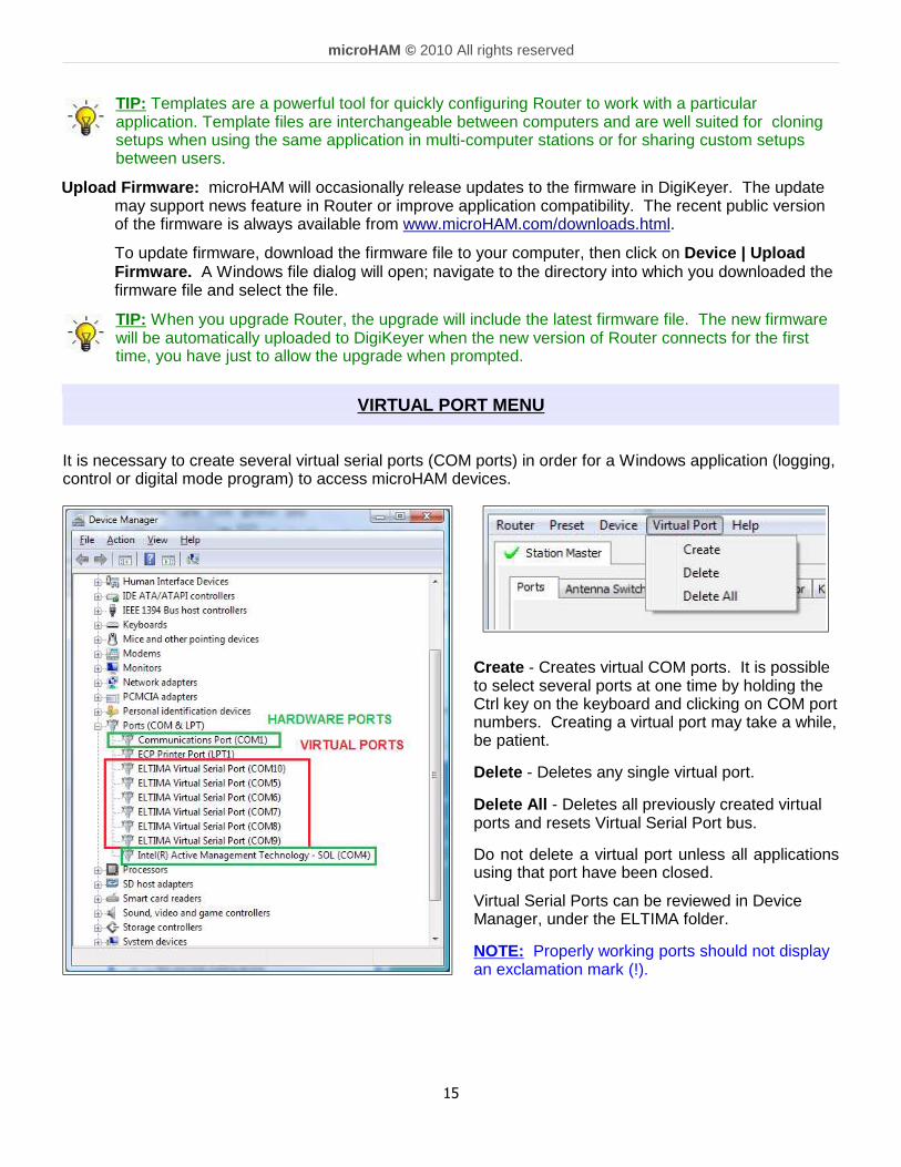
VIRTUAL PORT MENU
It is necessary to create several virtual serial ports (COM ports) in order for a Windows application (logging,control or digital mode program) to access microHAM devices.
Create - Creates virtual COM ports. It is possibleto select several ports at one time by holding theCtrl key on the keyboard and clicking on COM portnumbers. Creating a virtual port may take a while,be patient.
Delete - Deletes any single virtual port.
Delete All - Deletes all previously created virtualports and resets Virtual Serial Port bus.
Do not delete a virtual port unless all applicationsusing that port have been closed.
Virtual Serial Ports can be reviewed in DeviceManager, under the ELTIMA folder.
NOTE: Properly working ports should not displayan exclamation mark (!).
15

micro HAM © 2010 All rights reserved
HELP MENU
Manuals: Link to microHAM manuals located on your system.
Setup Guides: Link to software configuration guides for many common applications.
Cable Schematics: Link to cable diagrams.
Download Documents: Downloads microHAM documentation including updated manuals and setupguides. You may specify the products for which you want documentation.
NOTE: Requires an Internet connection.
microHAM Home Page: Link to www.microHAM.com
microHAM Downloads Page: Link to www.microham.com/contents/en-us/d29.html
Show Tooltips: When checked, small, single line help is displayed below the mouse cursor.
Update Router: Download and install the most recent version of Router.
About: Shows the Router's internal version number
Change logs: Shows the Router and firmware changes.
DEVICE CONFIGURATION TABS
There are three (3) tabs for configuring DIGI KEYER. Each tab controls a part of DIGI KEYER's functions.Any change to the first two (2) tabs are applied immediately to DIGI KEYER. Changes in Messages areNOT applied automatically. To store them use buttons Store or Store All .
Ports - used to assign virtual ports to the DIGI KEYER foruse by applications.
Keying - used to configure timing of the PTT signal,operation of the FSK keyboard and the audioprocessor.
Messages – used to store FSK messages.
16

micro HAM © 2010 All rights reserved
Ports Tab
Once the virtual ports have been created they must be associated with a specific device channel (e.g.,Control, CW, PTT, etc.). These assignments should correspond to settings of the application software andmust be configured first in Router then in the application (e.g., logging program, MMTTY, STREAM, etc.).
Proper configuration of the port assignments in this tab is c ritical for integration with loggers. Readthe following information carefully.
DigiKeyer has nine functions with indication of the state and settings applied by the host application
● CAT (uses RxD and TxD)● 2nd CAT (virtual “fork” for the main CAT channel)● FSK (uses TxD and optionally RTS/DTR for PTT)● 2nd FSK (uses TxD and optionally RTS/DTR for PTT)● CW (uses DTR or RTS)● PTT (uses DTR or RTS)● 2nd PTT (uses DTR or RTS) ● Squelch (uses CTS, DCD, DSR or RING)● Control (uses RxD and TxD)
General note: Do not assign virtual ports to those functions which are not used by the application. It isunnecessary and only consumes resources.
17

micro HAM © 2010 All rights reserved
CAT PORT & 2 nd CAT PORT
The CAT channel is used by application software to control transceiver frequency, mode, T/R switching andmany other parameters using a serial (CAT) protocol. Most modern radios implement some form of CAT butalmost every radio implementation is different. The functions controlled by the computer depend on theparticular application and radio.
NOTE: The port number assigned in Router MUST match the port number assigned in the hostapplication. First configure the virtual COM ports in Router then configure the application.
When a COM port is assigned in the Router but not inthe application (or the application is not running) Routerwill indicate the channel is closed .
When an application opens the COM port assigned for control (usually at start-up), Router shows the channel asopen and displays baud rate, data bits, parity and number of stop bits used by the application. For example,4800 8N2 means: 4800 baud, 8 bits data length, parity = none, and two stop bits.
Data flowing through the CAT channel is indicated by two arrows. A green arrow indicates data flow from theapplication to the radio and a red arrow indicates data flow from the radio to the application.
TIP: If the application provides for PTT (T/R) keying by radio control (CAT) turn this function OFF. PTTby CAT is not reliable because RFI can prevent the radio from switching back to receive. There is adedicated T/R switching channel for this purpose called PTT.
NOTE: If your radio does not supporthandshake (most do not). ConfigureDTR and RTS settings in yourapplication program (logger) for AlwaysOn or Always Off. Do not select“Handshake.”
For Router to determine the operatingfrequency and mode, it must knowwhat radio (CAT protocol) being used.To select the radio, click the Setbutton, choose your radio in the Radiocombo box, select communicationspeed in the Baud rate box, and setthe CI-V address for Icom and someTenTec radios.
TIP: Disable the Autobaudfunction in any Icom Radioused with Router. Configurethe radio, Router, and yourapplication software to operateat 9600 or 19200 baud.
Disable router queries – When this box checked, Router will not poll the radio for frequency and mode whenthat information is not available from the communication between the application and radio.
NOTE: "Disable router queries" disables Router polling only when the port has been opened by anapplication program. When the virtual port is closed, Router always polls the radio to support theautomatic switching functions of DigiKEYER. If it is necessary to disable all polling, select one ofthe "none" options in the Radio box.
18

micro HAM © 2010 All rights reserved
WARNING: DO NOT select "Disable Router queries" unless you have a specific reason to do so. Routeronly polls for information that is not requested by the logger and does not interfere with logger polling.Disabling Router queries may result in incorrect frequency and/or mode decoding and can have a seriousimpact on overall operation.
PW1 on radio bus – When this box checked, Router periodically generates an Icom "Transceive"broadcast to keep the PW1 synchronized.
NOTE: Check this box if you have an IC-PW1 or other Icom compatible accessory physically connected (in parallel with the transceiver). Do not check this box if the only connection is tothe transceiver and the PW1 or other other accessory is connected to the accessory CI-V PAport (described later).
SDR Tracking:
Tracking: This function allows an external receiver to track the transceiver attached to themicroKEYER II.
NOTE: The transceiver attached to DigiKEYER must be properly interfaced and CAT must befunctioning properly. Tracking does not work for “no radio” choices.
Radio: Specifies SDR receiver model.
Source QRG: Specifies whether the SDR will track the transceiver transmit or receivefrequency. .
Port: Specifies COM port used to communicate with the SDR.
Offset: Frequency offset between the receiver and transceiver. Default is 0Hz, resolution is1Hz.
NOTE: For specific receiver configurations, please refer to Appendix C..
The bottom two-thirds of the Radio window is a serial communication monitor. The monitor uses colors and tagsto indicate which device is responsible for the data. Black queries (H1-TX or H2-TX) and grey radio responses(H1-RX or H2-TX) are from the "host" application (e.g., logger), H1 indicates the host application on the mainCAT port, H2 is the host application on the 2nd CAT port. Green packets (R-TX and R-RX) are polls/responsesfrom/to Router and not routed to the application.
Router monitors the communication when the host application performs control and polls the radio periodicallyfor any missing information (VFO frequencies and mode). Because some applications do not poll the radioregularly or completely, Router must break this communication to update its internal state. In order to avoidconfusing the application when Router polls the radio, data from the application is buffered and sent to the radioafter Router receives a response to its query. If Router does not receive response to a poll within the timeallowed or does not understand the response, it displays "oldest query discarded" but forwards all data to thevirtual serial port to avoid confusing the application (logger).
Since USB transmits data in frames with a delay between frames, Router indicates frame boundaries with threedots (...). When a packet ends with three dots it means that the data continues in the next frame.
19

micro HAM © 2010 All rights reserved
2 nd CAT PORT
Beginning with version 7.0, Router provides unique control capability: the 2nd CAT Port is an intelligent data fork(software 'Y' connector) that allows a second application to share control of the radio. Router monitors whendata is sent from each application and routes the radio's responses to the correct virtual port.
IMPORTANT: Both applications must use same communication parameters (baud rate, data length, parity andnumber of stopbits) for proper operation!
Neither CAT port has priority. Polls/commands from the application are processed alternately. In order to avoidcollisions and confusion due to unexpected data, responses from the radio are returned only to the applicationthat generated the command. Unsolicited data such as automatic frequency/mode updates (Icom "transceive"packets or "Auto-information" data from Kenwood, Elecraft and recent Yaesu transceivers) is forwarded to bothCAT ports.
Due to physical limitation of data channel throughput and the controller capabilities in various transceivers,there are several important rules which must be observed.
● Combined data from both applications must not exceed maximum throughput of the radio control portand transceiver controller. In other words, the polling rate from one application may need to bedecreased to provide data space for the second application and vice versa.
● Applications must be tolerant of delayed responses from the radio. Each application must wait for theradio to respond when the another application is communicating with the radio.
● Due to protocol deficiencies in handling VFO split commands with many transceivers (particularlyIcom), split mode must be initiated and ended by only one application and manual split control (from thefront panel of the radio) should not be used.
NOTE: Despite extensive testing using various combinations of applications for the CAT and 2nd CATports, microHAM cannot guarantee proper operation with every potential combination of applications.
20

micro HAM © 2010 All rights reserved
FSK & 2 nd FSK PORTS
The FSK channel is used by the application program to send the FSK keying signal. FSK is used primarily forRTTY. It is very important to understand the difference between FSK and AFSK.
FSK is a digital (On/Off) signal from the computer serial port (or an external modem). This signal is used in thetransceiver to generate a frequency shift. FSK must be supported by the transceiver (this mode is commonlylabeled RTTY or FSK).
AFSK is a analog (audio) signal generated by the computer sound card (or external modem) used in thetransceiver modulation circuits for operating digital modes as RTTY, PSK31, AMTOR etc. Computer sound cardgenerated AFSK or PSK does not require special transceiver support and can be used in the LSB, USB or FMmode of the transceiver. Some radios have dedicated modes for AFSK (generally labeled PKT or DATA) withspecial features.
It is very important to properly adjust the audio drive level of an AFSK system so as to not overdrivethe first transmit audio amplifier stage in the transceiver and produce a wide, distorted signal, full ofintermodulation products. It is important to appreciate that distortion generated at this point due tooverdrive CANNOT be reduced or eliminated by the reduction of the microphone gain control – it isthe signal level that must be adjusted to be about the same as would be expected from amicrophone. The microphone gain control then becomes a form of transmit power control.
An initial indication of proper audio drive level can be seen on the ALC meter of the radio. Providedthat there is NO audio processing in circuit and that the microphone gain control is in its normaloperating position, then, if the ALC does not show or just starts to indicate during transmission, thesignal is likely to be clean. It is also important is to turn off the microphone compressor, ANY transmitaudio equalizer, AND transmit DSP when AFSK is used. DO NOT use any form of digitalmodulation (sometimes called "Transmit DSP") with AFSK or PSK. Some transceivers bypass thesecircuits automatically when signal is routed to the rear audio jack instead of the microphone jack, butsome do not (for example, the TS-850).
Edited by Geoff Anderson, G3NPA
If your transceiver supports FSK, use FSK for RTTY whenever possible. It's the only sure way to get aclean RTTY signal no matter the microphone gain or compressor (processor) settings on your radio.
When a COM port is assigned in Router but not in the application program (or the application is not running),Router will indicate the channel is closed .
When an application opens the COM port, Routerwill indicate the channel is open and display baudrate, number of data bits, parity and number of stopbits in use. For example, 45 5N1.5 means: 45Baud, 5 data bits, no parity, 1.5 stop bits.
The second FSK port is useful when operating split with radios that have two receivers (e.g., FT-1000, FT-2000,FT-9000, K3, Orion or IC-7800). The second instance of the RTTY program should specify "right channel" for itsaudio source and should be configured to use the 2nd FSK port for its FSK output.
Radios without a second receiver can use the 2nd FSK port for a second RTTY program with a different decodingalgorithm to provide diversity decoding and transmit from either program.
TIP: If you see a baud rate other than 45.5 baud (e.g., 4800 or 9600), the application is NOT configuredcorrectly for FSK RTTY operation.
PTT: The virtual port used for FSK can also support PTT (required by MMTTY). When you use MMTTY,select the PTT box and RTS will used for PTT. Do not use the FSK port for any other function.
21
micro HAM © 2010 All rights reserved
Invert: Some transceivers lack the ability to set the sense of the FSK input. If you cannot set the proper sense,check the invert box. This is normally necessary only with the TenTec Omni V, Omni VI and Kenwood TS-940.
Strict bps: Some programs rely on the the FSK port for proper PTT timing; they drop PTT (unkey) when theFSK port buffer is empty. With virtual ports, this may cause PTT to drop before the contents of a message(macro) are complete. 'Strict bps' disables the virtual port buffering and transmits one character at a time to theoutput. Due to the additional overhead, FSK output will be slightly slower but operation will be more reliable.
To test FSK operation from the computer to the radio, click on Test button with no port assigned or the portclosed. The Test button will generate "RY" two times.
CW PORT
By its very nature, USB is not well suited to transfer the real time events required for CW keying. Inaddition to the latency inherent in the USB protocol, delays due to CPU load, internal Windows messageprocessing (inter-process communication) and data flow from another peripherals sharing same the USBroot hub can result in transmitted characters that are garbled. To minimize these unwanted operatingsystem effects Router uses a specially developed oversampling and prediction algorithm to assure thesmoothest possible transfer of control signal events over USB. Using these techniques, CW keying in theRouter is, in most cases, usable up to 50 WPM if the application generates keying signals accurately anddoes not consume 100% of CPU time at the highest priority class.
Router allows assigning a virtual serial port for software CW using DTR or RTS signals. The DTR* andRTS* are identical to DTR/RTS except that the output is inhibited for one second after the COM port isopened. RTS*/DTR* should only be used with programs that cause unwanted key-ups during startup.
TIP: More applications use DTR for CW than RTS.
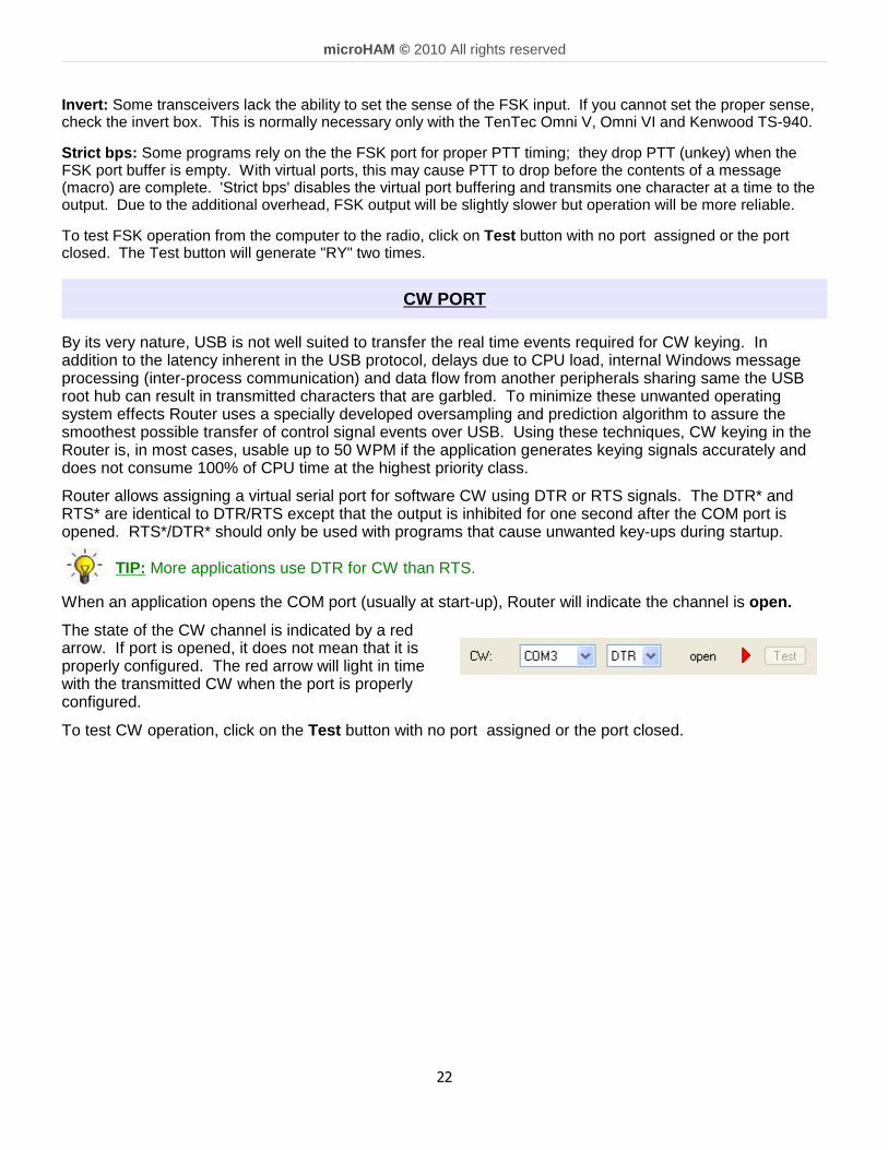
When an application opens the COM port (usually at start-up), Router will indicate the channel is open.
The state of the CW channel is indicated by a redarrow. If port is opened, it does not mean that it isproperly configured. The red arrow will light in timewith the transmitted CW when the port is properlyconfigured.
To test CW operation, click on the Test button with no port assigned or the port closed.
22

micro HAM © 2010 All rights reserved
PTT & 2 nd PTT PORTS
The PTT channel is used for T/R switching of the transceiver, Power Amplifier and Low Noise Preamplifier(LNA). An internal T/R sequencer assures 100% protection against transmitting through the LNA or hotswitching of the PA when the PTT channel is used for T/R switching. More information about T/R switching, DIGIKEYER PTT outputs and the sequencer is provided under the Keying Tab (page 21).
Router allows assigning virtual serial ports for PTT using the DTR or RTS signals. DTR* and RTS* are identicalto DTR/RTS except that the output is inhibited for one second after the COM port is opened and . should only beused with programs that cause unwanted key-ups during startup.
TIP: More applications use RTS for PTT than DTR.
The state of the PTT channel is indicated by a green arrow. If the port is opened, it does not mean it is properlyconfigured. When the port is properly configured, the arrow will light during the entire transmission. To test PTToperation, click on the Test button with no port assigned or the port closed.
The 2nd PTT channel is identical to the primary PTTchannel. 2nd PTT provides a way for a secondapplication to key the radio if the primary applicationalso controls PTT – for example, a logging programand CW reader/keyboard.
TIP: Always use serial PTT instead of the radio command PTT or VOX. It is the only way to assureproper sequencing of a Power Amplifier, LNA, or receive antenna switch.
To test PTT, click on the Test button with no port assigned or the port closed.
SQUELCH PORT
Even though most applications do not monitor the squelch and do not have the ability to perform specificfunctions based on its status, we have decided to include this feature in Router. Perhaps someday applicationswill be able to detect the squelch and use this information for automated functions like audio recording.
Router allows assigning a virtual serial port to squelch as CTS, DSR, DCD or RING.
When a COM port is assigned to the squelch channel in Router but not in the application (or no application isrunning), Router shows the channel as closed .
When an application opens the COM port (usually at start-up), Router shows channel as open.
When squelch is active, this state is indicated by a red arrow.
CONTROL PORT
The Control Port allows an application program (logger)that implements the microHAM Control (SO2R) Protocolto use the stored CW messages. This port shouldnormally be set to "none."
The Mon button opens a logging window that permits capture of Protocol data between the application andRouter for later analysis. The Control monitor operates the same way as the CAT port monitor. The buffercaptures the last approximately 20K of data. Do not enable logging unless necessary for debugging purposes asit imposes a minor performance penalty.
23

micro HAM © 2010 All rights reserved
KEYING TAB
The Keying tab includes controls for the USB Audio processor, PTT and FSK Keyboard.
Audio
NOTE: Audio controls are not available under Windows Vista and 7 due to operating system limitations.
Transmit Level: sets the level of the audio output from the digital to analogconverter. Preset the slider between 50 and 80% of full scale. Adjustthe drive to your transceiver with the TX pot on the front panel ofDigiKeyer.
RX sub & RX main: these "stacked LED" displays show the audio level into theanalog to digital converter. Adjust the RX #2 and RX #1 pots on thefront panel of DIGI KEYER so that the strongest signals onlyoccasionally show RED.
Sample Rate: sets the sample rate used for the RX level displays.
Note: Sample Rate defaults to OFF. Due to the way Windowshandles multiple access to sound cards, it is best to leave the samplerate OFF when not using the RX display to set levels.
Generate Test Signal: causes DigiKeyer to output a 1500 Hz audio tone forsetting the transmit output level.
TX Mixer: this button opens the Windows Volume Control (Playback Mixer) forthe selected sound card.
GET ID: this button will retrieve the name and number of the sound card usedfor transmit functions. The name can be used to verify that the correctsound card has been selected. The number can be used to configure software that identifiessound cards only by number.
Some tips from Geoff Anderson, G3NPA:
TIP: If you have achieved the correct settings for the transmit levels (with audiocompression disabled), changing from a single tone to the PSK idle should make transmitpower drop by at least 50% as observed on an RMS or average reading meter. Thischange in power is correct. If you do NOT see a 50% (or more) change, you are probablyover driving the radio. Please note that some radios have inbuilt power meters which givea PEAK reading and therefore the change in level discussed above will not be observed.
TIP: Don't fall into the trap of thinking that because the transmit signal on the waterfall looksgood that your actual signal is OK. All the waterfall is showing during transmit is the local audioand NOT the resultant transmitted signal.
24

micro HAM © 2010 All rights reserved
PTT – T/R KEYING
DigiKeyer has three (3) PTT outputs: PTT, PA PTT and LNA PTT. PTT is brought out to the DB15 Radioconnector. PA PTT and LNA PTT are available on RCA connectors at the DigiKeyer rear panel.
PTT is normally wired to the radio Accessory jackand is used to switch the radio intotransmit.
PA PTT is present at the DIGI KEYER rear panelRCA jack and is designed for switching apower amplifier. PA PTT is enabled bychecking the PA PTT box.
PA PTT will close before transceiver PTT bythe amount of selected PTT Delay and willopen at the same time as the transceiverPTT.
LNA PTT is present at the DIGI KEYER rear panelRCA jack and is designed for switching(bypassing) a low noise preamplifier (LNA)during transmit. LNA PTT is enabled bychecking the LNA PTT box.
LNA PTT will close before the transceiverPTT by the amount of selected PTT Delayand will open after the transceiver by thesame amount.
Serial port PTT: selects whether PTT is enabled.
PTT delay: amount of delay between activation of PA PTT and LNA PTTand the activation of the radio PTT. 0 to 2500 milli-seconds.
PA PTT: Enable PA PTT output
LNA PTT: Enable LNA PTT output
FSK from Keyboard
If an external PS/2 keyboard is attached to the DigiKeyer, Router supports additional settings for FSK.
Diddle LETTERS will generate the "LETTERS" character if nothing isbeing typed
UOS automatically generates the "Unshift on Space" function whenchecked
Type ahead enables a type ahead buffer for the keyboard.
QWERTZ layout configures DigiKeyer for the alternate keyboard layout
25

micro HAM © 2010 All rights reserved
FSK MESSAGES TAB
DIGI KEYER allows defining nine messages of up to 50 characters each which are stored in non-volatilememory. Each memory may repeat with a programmable delay (loop) or call another memory (chain).
Commands which may be included in a memory are:
CR & LF: Insert Carriage Return/Line Feed
Jump to: used for looping a message or calling another messageDelay: sets the delay in seconds before looping or calling another message
Store: saves one message to DIGI KEYER memory Store All: saves all messages to DIGI KEYER memory
Load from File: loads all messages from fileSave to File: saves all messages to file
Messages can also be saved and replayed also using an external keyboard attached to the Remote jack.
26

micro HAM © 2010 All rights reserved
6 - EXTERNAL KEYBOARD
DigiKeyer allows generating FSK signals from a PS2 keyboard attached to the Remote jack.
NOTE: The keyboard must be PS/2. A USB keyboard with PS/2 adapter will not function properly.
Number Pad Key Standard Key Function
NUM LOCKStart/Stop recording of message -(record mode is indicated by NUM LED, if present)
NUM 0 ESCPlayback: Stop transmitting (clear message/buffer)
Recording: abort recording without saving the message
NUM 1 – NUM 9 F1 – F9Playback: Play message
Recording: Select message slot to record
NUM DELLoop last message – default is one second. Following NUM DEL with anumber on the numeric pad will set the delay
Enter Transmit CR/LF
F10 Toggle PTT
CAPS LOCK Enter FSK mode (CAPS LED is on when in FSK mode)
SpaceTransmit a space. If “type ahead” is selected, the character is pushed intothe type ahead buffer and transmitted in sequence
0-9, A-Z !“$&='(),-./:;?
Transmit the character. If “type ahead” is selected, the character is pushedinto the type ahead buffer and transmitted in sequence
7 - PACKAGE CONTENTS
The product includes DigiKeyer, USB cable, and CD-ROM containing the microHAM USB Device Routerprogram and documentation. If the shipment is incomplete, please contact us at the following address:
E-mail: [email protected]
fax : +421 2 4594 5100
by Post: microHAM s.r.o.Nadrazna 3690028 Ivanka pri DunajiSLOVAKIA
27

micro HAM © 2010 All rights reserved
8 - WARRANTY
microHAM warrants this product for three (3) years. The product must not be modified in any way or the warrantyis voided. Cables are warranted against defects in materials and workmanship for a period of 60 days.
What is covered: During the warranty, microHAM, s.r.o., will repair or replace defective product at their solediscretion. You must send the unit postpaid with a copy of the original invoice to the distributor from whom youpurchased the product. microHAM will pay return shipping.
What is not covered: This Limited Warranty does not cover (1) correction of installation or software errors in theuser's computer(s), (2) damage caused by misuse, negligence, user modifications or failure to follow the usermanual, (3) connection to improper or excessive voltage or voltage surges, (4) the incorrect installation of anycables connected to the device by the user or (5) weather related storm, lightning or electrostatic dischargedamage.
micro HAM USB Device Router (the software) is provided “as is” without guarantee of compatibility with anyspecific operating system, computer, peripheral or accessory.
microHAM assumes no liability or responsibility for damage to other devices or injuries to persons as aconsequence of using our products.
If the terms of the above warranty are not acceptable, return the unit, all associated documents and accessoriesin the original unopened package, prepaid, to microHAM or to your supplier for refund less shipping and arestocking fee.
9 - SPECIFICATIONS
DigiKeyer is a multi-mode interface between computer and transceiver. It has been optimized for amateur digitalmodes and includes a high performance USB sound processor.
DigiKeyer is connected to the computer using a single A-B USB cable which is included.
The transceiver and DigiKeyer are connected by single radio cable terminated on one side by a DB15M and onthe other side by the appropriate plugs for the specific transceiver. The cable carries power for DigiKeyer, audio,CAT control and keying. The appropriate transceiver interface cable is specified when DigiKeyer is purchased.
If a Windows PC running the "microHAM USB Device Router" program is connected, DigiKeyer works as acomputer interface and sound card. It transfers all control signals generated by the application program betweenthe computer and transceiver. Software compatibility is provided by using virtual serial ports. Router monitorsthese virtual ports and transfers any data or commands by USB to the micro controller in DigiKeyer. DigiKeyerprocesses this data and sends it to the physical ports of transceiver as CAT, CW, and PTT functions.
The USB sound processor in DigiKeyer independently provides analog to digital conversion of audio from thetransceiver and transfers it via USB to the computer where the operating system processes that data as a “soundcard.” The USB sound processor also receives digital audio from any applications running on computer andconverts that data into audio signals to modulate the transceiver.
microHAM Device Router is not required in order to enable the USB sound functions. The USB sound processoris supported directly by Windows, Apple OS 10, and LINUX.. It may be used by any application compatible withthose operating systems.
28

micro HAM © 2010 All rights reserved
10 - System Considerations
DigiKeyer can be used with a wide variety of software. The capabilities of those packages will have largeinfluence on the level of computing power needed to utilize DI.
When used with Windows based contest logging applications like CTWin, N1MM Logger, Win-Test, andWriteLog or Windows based general logging applications like DXBase, DXLab Suite, DX4WIN, Logger 32 andothers, the microHAM control and interface application “microHAM Router” must run along side the applicationprogram. Since both the logging programs and microHAM Router are real-time applications, systemperformance will be dependent on both CPU speed and the amount of available RAM.
While microHAM Router will run on slower computers, the minimum tested system is a 1.6 GHz Pentium IV,Windows 2000, 512 MB RAM, CD-ROM, and USB 1.1 port. Whether Router can run as designed on slowermachines with less memory and leave enough resources for application programs has not been determined.microHAM Router is not supported on any 16 bit version of Windows (95, 98, ME, SE).
In order to provide sufficient performance for simultaneous operation of microHAM Router, a logging application,Internet connectivity and other accessory programs, the recommended system is a 2 GHz PC compatiblecomputer with Windows XP Home or higher, 1 GB RAM, CD-ROM, root USB 2.0 port, a transceiver withsupported control protocol and logger, control, or digital mode software.
DigiKeyer is also compatible with Apple Macintosh systems running OS 10.5 or later. It is directly supported byMacLoggerDX (www.dogparksoftware.com/MacLoggerDX.html) by Don Agro, VE3VRW as well as µH Routerand cocoaModem (http://homepage.mac.com/chen/w7ay/Site/Applications/index.html) by Kok Chen, W7AY.
11- Hardware Specifications
USB: USB 2.0 Full speed , USB 1.1 compatible
Power consumption: USB – less than 100mA; Transceiver – less than 200mA at 13.8V (max. 16V)
Radio Port: RxD, TxD – max. 57,600 BaudLevels: Jumpers selectable TTL, inverted TTL, open collector bus, RS232
CW: open collector, max 30V/400mA
FSK: open collector, max 30V/400mA
PTT: open collector, max 30V/400mA
Audio Out: 600 Ohm, 3V p-p max. 3dB bandwidth: 0.2 - 6KHz typicalSecond harmonic: -84 dB typical Third harmonic: -72 dB typical D/A Sampling rates: 32000, 44100, 48000 Hz.
Audio In: 50K Ohm, max 4Vpp3dB bandwidth: 0.2 - 6KHz typicalAbsolute noise floor: -82 dBm @600 Ohms typicalDynamic Range: 82 dB typicalA/D sampling rates: 8000, 11025, 16000, 22050, 32000, 44100, 48000 Hz.
Dimensions: W 175mm (6 7/8") x H 44mm (1 3/4") x D 101mm (4")
Weight: 1100g (2.4 lbs.)
29

micro HAM © 2010 All rights reserved
DECLARATION OF CONFORMITY
Federal Communications CommissionStatement (USA)
This device complies with Part 15 of the FCC Rules. Operation is subject to the following twoconditions: (1) this device may not cause harmful i nterference, and (2) this device must accept anyinterference received, including interference that may cause undesired operation.
European Union Declaration of Conformity
micro HAM, s.r.o. declares that the products:
Product Name: DigiKeyer
Conforms to the following Product Specifications:
EN 55022: 1998 Class B following the provisions of the Electromagnetic Compatibility Directive 89/336/EEC
30

micro HAM © 2010 All rights reserved
APPENDIX A – CONNECTORSRadio - DB15
Pin # Label Description
1 Power +13.5V 12 - 16V DC input
9 CAT IN Control port input
2 CAT OUT Control port output
10 SQL1 Level squelch input
3 SQL2 Impedance squelch input
11 PTT PTT output "open collector"
4 CW CW output "open collector"
12 AUX reserved
5 FSK FSK output "open collector"
13 AUDIO OUT S Radio AUDIO input signal
6 AUDIO OUT GND Radio AUDIO input ground
14 AUDIO IN MAIN S Radio AUDIO output signal main receiver
7 AUDIO IN MAIN G Radio AUDIO output ground
15 AUDIO IN SUB S Radio AUDIO output signal sub receiver
8 AUDIO IN SUB G Radio AUDIO output ground
SHELL GND Radio and power GND
REM – miniDIN 6
Pin # Label Description
1 PS/2 DATA TTL PS/2 DATA line
2 n/c Not connected
3 GND Connected to the system ground and case.
4 +5 V +5V output, max.100mA.
5 PS/2 Clock TTL PS/2 CLOCK line
6 n/c Not connected
SHELL GND Connected to system ground and case
31

micro HAM © 2010 All rights reserved
APPENDIX B – RFI Considerations
A few guidelines to eliminate problems caused by RFI:
1. Proper grounding of all electronic equipment is critical. A modern station contains many, diverse, typesof interconnected and interrelated equipment: transceiver, power amplifier, computer, control boxes,switch boxes, and power supplies. Each of these must be individually grounded with a separateconnection to a single common ground point, thus forming a star ground connection.
Proper grounding of computers, both "desktop" and laptop is often overlooked. A separate groundconnection should be run from the computer to the station common ground point. The best place toground a computer is a screw with a good connection to the case. On a laptop, this is often the retainingscrew on a D-sub connector (e.g, VGA output); on a "desktop" it is often the screws holding the powersupply.
It is absolutely important to prevent ground currents from flowing to the common ground point by way ofthe signal cable. If you use a microHAM "keyer," a good test is to remove the DB15/DB37 connector andUSB cable from the keyer and measure the resistance from the shell of the DB15/DB37 to the shell ofthe USB cable. There should be NO MORE than FIVE (5) Ohms (and preferably less than TWO Ohms)between them.
Note: many PC manufacturers fail to provide an adequate connection between the shell of the USBconnector and the PC case. If this is the case, a connection can be established by bridging a foldedpiece of aluminum foil between the shell of the USB connector and the PC case.
2. Power all your equipment from a single wall outlet. The "safety ground" often exhibits excessive noisebetween power outlets - sometimes often due to other equipment powered from the same branch circuit.It is always better to avoid this source of noise/interference. It is also a good idea to check the powerdistribution for loose connections, reversed neutral/ground, open ground and other wiring problems.
3. Sometimes, the USB cable can be a source of RF interference - the cable might have inadequateshielding or the transceivers in PC might be improperly designed causing data flowing inside the cable tobe reflected as a common mode current on the shield of the cable. This common mode current canradiate a significant "digital noise." If this is the source of your problems, it can be significantly reducedor eliminated using ferrite chokes on both ends of the cable. Two or three turns through a #31 mixFT240 toroid are better than the common snap-on ferrites of unknown mix.
4. Often, another cause of RFI problems is a common mode current flowing along the antenna feedline intothe shack. It is a common misconception that the only thing required of a feedline is that it have lowSWR. Unfortunately, a low SWR does not guarantee low common mode current. These common modecurrents are conducted into the shack where they can radiate from the feedline, induce currents in anynearby metal object, and/or be conducted into the interconnected equipment. Common mode currentson a feedline are indicated by problems that differ in intensity from one band to another or from one endof the band to another, by problems that change when a feedline is moved or its length changed, wherethe problem moves from one piece of equipment to another based on band, and/or where the severitychanges with transmit power level. The solution is to use common mode chokes to prevent the currentfrom entering the shack. This topic has been given thorough treatment in recent works by W1HIS andK9YC.
W1HIS: http://www.yccc.org/Articles/W1HIS/CommonModeChokesW1HIS2006Apr06.pdfK9YC: http://www.audiosystemsgroup.com/RFI-Ham.pdf
32

micro HAM © 2010 All rights reserved
APPENDIX C – Tracking
NOTE: Tracking is experimental code started in Router 7.5.0 for linking the transceiverfrequency to a tracking receiver. Mode linking and bidirectional frequency tracking are notcurrently supported.
microHAM will be expanding features and adding support for additional radios in the future.The initial version has been tested with Perseus SDR only.
PERSEUS
Radio: PERSEUS
Port: COM10
Source QRG: Defines which frequency will be used for SDR tracking
Offset: Specifies frequency offset from tracking frequency send to SDR for tracking.
NOTE: COM10 is the default COM port for PERSEUS can only be changed in the Windowsregistry (refer to the Perseus manual). Make sure that the COM10 is not used by any otherdevice in PC. Then create virtual COM10 in Router and do not use this COM port number forany purpose other than tracking.
33