dlms_riz
TRANSCRIPT

Implementing DLMS/COSEM in Smart Meters
Gordan Štruklec*1, Joško Maršić*2 *RIZ Transmitters Co., Božidarevićeva 13, 10000 Zagreb, Croatia
1 [email protected] 2 [email protected]
Abstract—For some time now there have been initiatives
(European SmartGrids, GridWise) to develop new visions of the future electric system – smart grid, triggered with the increasing demand for electricity and the drive for lower carbon generation, and made possible by new advances in technology. In order to deliver electric energy reliably and efficiently to end-users, smart system has to monitor and control demand appropriately. This can be done through the use of smart meters. However, for long there has been no unique and generally accepted protocol for delivery and interpretation of meter data, what has generated many problems and difficulties for both AMI system developers and utility distributors. DLMS/COSEM is widely accepted standard-based language for meter communication, whose main goal is interoperability among metering equipment. Although it is a well-defined protocol, integrating it into a meter sets new challenges in front of a developer like resources management and compatibility with current HW and SW platform.
I. INTRODUCTION
A. Smart grids The European Technology Platform SmartGrids defines
smart grids as electricity networks that can intelligently integrate the behavior and actions of all users connected to it - generators, consumers and those that do both – in order to efficiently deliver sustainable, economic and secure electricity supplies [1]. Every device that consumes electricity is part of the grid – not only the devices (or equipment) owned and operated by the utilities, but also everything connected to the electricity network (appliances in homes, HVAC equipment, streetlights in cities and towns). The four key elements of a smart grid are identified as flexibility in fulfilling customer’s needs, accessibility to all users, reliability in quality and in security of power supply, and interactivity [2]. Among all other benefits, which smart grids offer to the utilities, end users and community in general, a few of them play important roles in reducing carbon emissions and improving energy efficiency. These benefits come from the optimization of grid operation and usage (e.g. reducing losses) and grid infrastructure on one side, and on the other providing consumers with greater information and options for choice of supply, allowing them to play a part in optimizing the operation of the system. The latter can be achieved by helping consumers to participate in the market not only by using their energy more efficiently (e.g. through smart metering) but also by allowing consumers to act also as producers selling back their excess electricity (e.g. plug-in electrical vehicles).
A fully automated power delivery network that would be able to monitor and control electricity flows to every customer and node, ensuring two-way flow of electricity and real-time information between the power plant and appliance and every node in between, imposes the incorporation of new and advanced technologies, many of which today come under the term ‘smart metering’ [2].
Although not as broad set of technologies and solutions as smart grid (Fig. 1), smart metering can encourage consumers to reduce their demand (load) when prices are high or when system reliability or power quality is at risk. In that way smart meters enable the provision of services (like demand management) to directly influence customer behavior and to become an important part of a smart grid.
Fig. 1. Generalized diagram of a smart grid [1]
B. Smart metering All the information that energy suppliers (service
providers) provide to their customers is based on the meter data. Based on this data the billing is carried out, anomalous energy consumption and fraud can be detected, warnings and alarms are sent (e.g. the remaining credit in the case of pre-paid contracts). Furthermore, the whole customer's consumption profile can be created and according to it various tariff models can be offered to a customer in a new contract, and in the case of irregular payment the customer can be automatically switched off the grid (switching on the grid has to be done manually because of safety reasons). A two way communication on this level is mandatory to allow intelligent

functions regarding demand side management, distributed energy resources and energy savings.
Main function of an Automatic Meter Reading (AMR) system is gathering meter data for billing in an automated way. Various standard-based techniques enable local or remote connections to meters, e.g. IEC62056-21, IEC62056-31, M-bus, GSM, GPRS, PSTN, Internet, PLC.
According to demands set forth earlier in the texts, the conventional functionality of AMR is changing in the direction of smart multi-metering or multi-functional Advanced Metering Infrastructure (AMI) capable of creating value for energy consumers, network operators, metering operators and retailers. The term AMI refers to systems that measure, collect and analyze energy usage data, from advanced devices such as electricity meters, gas, heat and/or water meters, through various communication media on request or on a predefined schedule. Advanced functionalities provided by an AMI system, like customers relation management, demand side management, local power quality monitoring etc., give the opportunity for various business processes: customer management including supplier change, energy supply / billing, (pre)payment, load management, network condition and health monitoring, meter condition and health monitoring, outage management or energy services [3].
Regarding (electricity) meters this means providing two-way communication and supporting various functionalities, of which energy consumption measurement is basic, but today even not the most demanding from a developer's point of view. An electricity meter has to provide the data about measured energy consumption and demand - if possible both imported and exported energy, about load profiles, power quality, or customer information. The meter should also enable the functionalities like load monitoring and management, and event monitoring and logging.
II. DLMS/COSEM For the implementation of an efficient AMI system the
devices have to be interoperable. There is a need to define universal data protocols so that all the partners in the communication chain can reliably and successfully receive and send messages, and to unambiguously excerpt and interpret useful data. There is a need for communication standards. DLMS/COSEM is the common language such that the partners can understand each other [4]. There are many standards and protocols disposable for AMI. In Table I the field of application for some of the AMR/AMI technologies and protocols is presented [3]. Table II presents communication media supported by these protocols.
DLMS/COSEM covers all the AMR/AMI application fields and supports all the communication media (except maybe wireless mesh networks). DLMS stands for “Device Language Message specification” and it is a generalized concept for abstract modeling of communication entities. COSEM is “COmpanion Specification for Energy Metering” – it sets the rules, based on existing standards, for data exchange with energy meters.
TABLE I
PROTOCOLS AND TECHNOLOGIES FOR AMR/AMI – FIELD OF APPLICATION
Specification
Field of application Data
model Local AMR
Remote AMR
AMI Home automation
IEC 61334 PLC Y Y Y
IEC 62056-21 'FLAG' Y Y
IEC 62056-31 Euridis Y Y
IEC 62056 DLMS/COSEM
Y Y Y Y Y
EN 13757 M-bus
Y Y Y Y
PRIME Y Y Y
TABLE II PROTOCOLS AND TECHNOLOGIES FOR AMR/AMI – SUPPORTED MEDIA
Specification Communication media supported
Local bus GSM GPRS Internet PLC
IEC 61334 PLC Y
IEC 62056-21 'FLAG' Y Y Y
IEC 62056-31 Euridis Y
IEC 62056 DLMS/COSEM
Y Y Y Y Y
EN 13757 M-bus Y
PRIME Y
DLMS/COSEM is usually promoted through the 3 step
approach (Fig. 2) [5]. COSEM defines the utility type and communication media independent object model for metering applications: object names and identifiers on the display (OBIS code – Object Identification System), from abstract to energy type specific codes. DLMS defines services to access object elements transported by application protocol data units (APDU), which are common to all objects. Finally, DLMS/COSEM defines profiles to access communication media like PSTN/GSM, Internet, Euridis, M-bus, or PLC. Through these media packets are transported using OSI/Internet based protocols like HDLC, TCP-UDP/IP, ASN.1, or ACSE.
Every parameter in a meter is represented by a COSEM object – instance of a class. All objects of the same class have the same attributes and methods. For example, meter parameters like active A+/A- or reactive R+/R- energy in first tariff can be instances of the register or extended register class, whereas maximum demand P+/P- or Q+/Q- can be of the class register, extended register or profile generic. Register objects are modeled through logical name, value and scaler-unit

attributes, while extended register objectattributes: status and capture time. If e.genergy in tariff 1 has to be read out oprovides GET-requests to acquire all needdata - value and scaler-unit, whereby inunambiguously interpreted.
Fig. 2. DLMS/COSEM 3 step approa
Further in text the real implementation o
object model in a smart meter is presguidelines and examples provided, whereafunctional issues still had to be set forth.
III. MAKING THE METER SMA
As already stated in text, implementing a meter gives to the meter the opportunitwith other compatible devices in an AMI spart of smart metering network. Is it really s
Nowadays in Croatia there are still interoperability issues. There are many typvarious manufacturers installed, supcommunication protocols, mainly IEC6205or RS485 interface), IEC62056-31 and(through optical or RS485 interface). To reaall types one needs to use different PC softwis no software that supports all protocols. Ialthough the meters support the samedifferent variants of data modeling are usapplication fully understands only the messadata model and not from any other (tdiscussed). This imposes many questions tintegrators, and directly effects meter mmust comply with the utility supplier’s rebring their equipment on the market. Nevert
ts have two more g. accumulated A+ f a meter, DLMS
ded object attribute nformation can be
ach [5]
of DLMS/COSEM ented with useful as some important
ART DLMS/COSEM in ty to communicate system, making it a so? compatibility and
pes of meters from pporting various 56-21 (optical, CS d DLMS/COSEM ad out all meters of ware because there In addition to that,
e DLMS/COSEM, ed so that one PC ages from a certain this will be later to the AMI system
manufacturers, who equests in order to theless, making the
meter DLMS/COSEM complianin the course of solving all ment
A. Compatibility with ‘old’ harIn order to easily integrate t
into existing AMI system, thfunctions have to be further supthis application [6] there are mbasis to build-up the new smareactive (R+, R-) energy mmaximum active (P+, P-) and retariffs; energy and demand oremote or local billing period months; log book for last 64phase measurement; current anquality values like power undervoltage measurement annumber of readouts and conclock, date and calendar; prograintegrated ripple control reprogrammable LCD sequence; off/on; autonomous battery opetwo-way optical IEC62056-21 cway RS485 communication int31 interface.
All these functions exhaustresources, FLASH and RAM inmake some decisions about reunused features (of course it cocourse of building up the wholeit was too expensive). Current tneed for DLMS/COSEM, opticdecision was made to exclude support DLMS through opticalAlthough the new version of IEthe support also for DLMS, thealready installed and networkedsupporting system will be solveconcentrator with DLMS-Euridi
After the platform adjustmechanges were in turn. The supadded on top of current protocol
B. Smart meter model DLMS/COSEM is promoted
two essential documents GreenAll current meter data had to baccording to the Blue Book, andto the Green Book.
First, all the objects were dcode was appended to each groups in a hierarchical structidentifies the energy type meacodes, and A=1 identifies elecidentifies the measuring channthe physical quantity measured,the processing methods and cgroup E is used for identifying r
nt is a must, as a start off point tioned issues.
rdware and software the new DLMS/COSEM meter he most of the current meter pported. In the meter chosen for many functions which are the art meter: active (A+, A-) and measurement in 1-4 tariffs; eactive (Q+, Q-) demand in all f the last 18 billing periods; reset; load profile for last 4
events; current, voltage and nd last calendar year’s power
failures, overvoltage and nd logging; tamper detection; nfiguration changes; real-time ammable time switching table; eceiver; tariff-switch inputs;
load limitation and switching ration of 10 years; self-testing; communication interface; two-terface or two-way IEC62056-
t almost all of the available n the MCU. It was necessary to emoving some of the usually ould have been thought in the e new platform, but at the time trend in the market showed the
cal and RS485 interface. So the IEC62056-31 interface and to
l and RS485 interface instead. EC62056-31 (Euridis) proposes e problem of the integration of d Euridis meters into a DLMS ed by the use of the smart data is routing [7].
ents had been made, firmware pport for DLMS/COSEM was ls’ stack.
d by DLMS UA, through the n Book [8] and Blue Book [9]. be mapped to COSEM objects d all data messaging according
defined, enumerated and OBIS object. OBIS uses six value ture (Fig. 3). Value group A
asured, A=0 identifies abstract ctricity codes. Value group B nels. Value group C identifies while value group D identifies country specific codes. Value rates or can be used for further
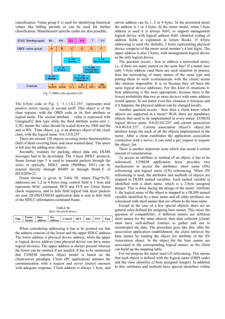
classification. Value group F is used for idvalues like billing periods or can be classification. Manufacturer specific codes a
Fig. 3. OBIS code structure [10
The 6-byte code in Fig. 3, ‘1.1.1.8.2.255positive active energy in second tariff. Thclass register, with the OBIS code as itslogical name. The second attribute – valueUnsigned32 data type while the third attri3,30} means the value should be scaled dowunit is Wh. Time object, e.g. is an abstract class, with the logical name ‘0.0.1.0.0.255’.
There are around 150 objects covering m(half of them covering basic and most wanteis left also for adding new objects.
Secondly, routines for packing object messages had to be developed. The 3-layeframe format type 3 is used to transmit pwires or optically. HDLC mode (9600bentered directly through RS485 or throIEC62056-21.
Frame format is given in Table III, waddresses are 1,2 or 4 bytes long, control represents MAC command, HCS and FCScheck sequences, and in Info field logical are sent. DLMS/COSEM application data iof the HDLC information command frame.
TABLE III
HDLC FRAME FORMAT
Flag Frame format
Dest. address
Src. address Control HCS
When considering addressing it has to b
the address consists of the lower and the upThe lower address is physical device addreis logical device address (one physical devlogical devices). The upper address is alwathe lower can be omitted if not needed. It hthat COSEM interface object model client/server paradigm. Client (PC applicacommunication with a request and servewith adequate response. Client address is a
dentifying historical used for further
are also possible.
]
5’, represents total his object is of the s first attribute or e is expressed with ibute scaler-unit {-wn by 1000 and the object of the clock
meter functionalities ed data). The space
data into DLMS er HDLC protocol, ackets through the
bps, 8N1) can be ough Mode_E of
where Flag=0x7E, field is 1 byte and
S are 2-byte frame link layer packets
is sent in Info field
Info FCS Flag
be pointed out that pper HDLC address. ss, while the upper
vice can have many ys present whereas
has to be mentioned is based on the ation) initiates the
er (meter) answers always 1 byte, and
server address can be 1, 2 or 4the address is 1 or 4 bytes. In address is used it is always 0logical device with logical addaddress fields is explained addressing is used (by default),device comprise of the meter seupper address is also 2 bytes, was the only logical device.
The question occurs - how ti.e. if there are many meters ononly 1-byte address (and therethen the networking of many putting them to work (commulike mission impossible. It is same logical device addresses. byte addressing is the most aplowest probability that two or mwould appear. In our meter eveif it happens, the physical addre
Another question occurs – hobjects are supported in a metobjects that need to be implemelogical device name ‘0.0.42.0.0‘0.0.40.0.0.255’. Current assattribute keeps the track of all tmeter. After a client establishconnection with a server, it canthe object_list.
There is another important isamount of consideration.
To access an attribute or mereferenced. COSEM applicmechanisms to access the referencing and logical name referencing is used, the attributmapped to DLMS named variaidentified with a short name, integer. This is done during the1, the logical name of the objecvariable identified by a base nareferenced with short names tha
Except in the case of a fewgeneral rules defined for assigniquestion of compatibility: if dshort names for the same objecmust have well-defined routmisinterpret the data. The procassociation application establisbase names by reading the oAssociation object. In the obassociated to the correspondingcan build up the mapping table.
For our purpose the meter usthat each object is defined withand the class identifier (2-byte to this, attributes and methods
4 bytes. In the presented meter the meter model, when 1-byte 0x03, to support management dress 0x01 (detailed coding of in Green Book). If 4-byte
, 2 bytes representing physical erial number’s 4 last digits. The with management logical device
to address a networked meter, n the same bus? If a meter uses e are such situation in praxis),
meters of the same type and unicate with the client) seems so because they all have the For this kind of situations 4-
propriate, because there is the more devices with same address en this situation is foreseen and ess can be changed locally. how does a client know which er? Well, there are mandatory ented in every meter: COSEM 0.255’ and current association sociation object’s object_list the objects implemented in the
hes the application association n send a get_request to acquire
ssue which also needs a certain
ethod of an object, it has to be ation layer provides two attributes: short name (SN) (LN) referencing. When SN
tes and methods of objects are ables. Each named variable is
which is a 2-byte unsigned e design of the meter. Attribute ct is mapped to a DLMS named ame and all other attributes are at are offsets to the base name. w special objects, there are no ing base names. This raises the different meters use different cts, then data collector (client) tines to gather and not to cedure goes like this: after the hment, the client retrieves the bject_list attribute of the SN
bject_list the base names are g logical names, so the client
ed LN referencing. This means h the logical name (OBIS code)
unsigned integer). In addition have special identifiers within

each class (all of these are defined and can be easily found in [4] and [9]). Although supporting LN referencing means slightly more complex firmware than in the case of SN referencing, it also gives the opportunity to support more objects than in the case of SN referencing. However, what seems to be the major advantage comparing to SN, LN object names are understandable to all DLMS/COSEM supporting equipment with no need for special mapping tables. In that way the metering data can be acquired and parsed easily and efficiently.
Fig. 4 shows the block diagram of the new meter after all the functionalities were defined.
Analog Front End
R,S,T,N, 230V, 50Hz
Power supply RCR
LCD
Buttons,Tariff switch
FRAM/EEPROM
MCUINPUTS
RELAY:Switch off/on
Battery
Optical interface-calibration
Communication interface
optical RS485
Fig. 4. Block diagram of the new meter
What still needs to be further considered is the presentation
of data values. For example, a client wants to read total positive active energy out of a meter: object logical name ‘1.0.1.8.0.255’, class identifier 0x0003 - register, attribute 2 - value (Fig. 5).
<GetRequest><GetRequestNormal><InvokeIdAndPriority Value="81" /><AttributeDescriptor>
<ClassId Value="0003" /><InstanceId Value="0101010800FF" /><AttributeId Value="02" />
</AttributeDescriptor></GetRequestNormal>
</GetRequest>
Fig. 5. Typical DLMS/COSEM request
The meter sends the value 1234 coded as unsigned 32-bit integer and attribute 3 (scaler-unit) {-3,30}. This means the energy is 1,234 kWh. However, DLMS/COSEM gives the opportunity for the developer to code this value also as 32-bit signed integer, 8, 16 or 64-bit signed/unsigned integer, octet string or visible string. This also causes compatibility issues (at the time there is no software that covers all possible variants of data interpretation) and problems for billing system management.
C. Testing and verification After the meter object model had been developed, the
implementation had to be tested, verified and finally, certified. DLMS UA certifies a meter in the way that the client CTT
software [11] runs a sequence of tests on the meter and creates report files, which are then verified by DLMS UA. If the meter passed all tests correctly a certificate is issued for that meter type and the meter is listed on DLMS-compliant equipment list.
PC runs CTT tests locally through COM port. It tests the meter’s HDLC, APPL and COSEM layer. However, it does not present the meter data in a user-friendly manner, so it is good for testing only to the certain point. Unfortunately there is no commercial software which does this. There is a worthwhile attempt with free Icube software [12] which formats DLMS requests and responses in XML and is quite easy to use. This is the issue that still needs to be worked on.
D. Further improvements DLMS UA has recently made extensions to the protocol to
support more of the smart metering functionalities: multi-metering, messages for the customer, load limitation, connect/disconnect, firmware upgrade, status/fraud monitoring. Messages for the customer are displayed on the meter LCD or customer display. They can show the reason for disconnect, threshold limitation values, impending credit shortage etc. For this purpose new objects of Data class are defined: ‘0.0.96.13.0.255’ customer port and ‘0.0.96.13.1.255’ display and customer port. Load limitation is handled by a Limiter-class object and it enables remote setting of thresholds and anticipation of credit shortage. Disconnect-class object supports remote, manual or local disconnect/reconnect in case of credit shortage, contract closure or emergency situations. These actions involve higher level of security to access the object. For the purposes of firmware bug correction or adding new functionality there is new COSEM Image transfer class. It enables remote update/upgrade of meter firmware.

IV. CONCLUSION Smart meters are crucial part of an AMI system. Adding
smart features to a meter means a must have for the utility provider, for the manufacturer it means fundamental step on the way to the market, for the developer it means more complex firmware, adjusting current (or new) HW/SW platform, solving problems like compatibility, interoperability and many more. DLMS/COSEM approach not only helps solving these issues, but also makes the process of smart meter development much easier.
Although DLMS/COSEM is a well defined protocol and object model, certain matters still have to be defined with more details (too broad data presentation possibilities, unnecessary short name referencing). Besides, the lack of the PC client application which includes all (or most of) DLMS features and which is able to interpret data in a user-friendly way makes the integration process more difficult and more time-consuming.
Nevertheless, at the moment DLMS/COSEM is the right choice to make smart meters really smart and to talk to each other. And it seems to stay that way for some time.
REFERENCES [1] (2011) The SmartGrids – European Technology Platform website.
[Online]. Available: http://www.smartgrids.eu/ [2] J. S. Jones, “Smart Meters for Smart Grids”, in Metering International,
2006, Issue 4, p. 70-71. [3] “D2.1/4 State-of-the-art technologies & protocols”, The OPEN meter
Consortium, 2009. [4] (2011) DLMS UA website. [Online]. Available:
http://www.dlms.com/information/whatisdlmscosem/index.html [5] G. Kmethy, “IEC 62056 DLMS/COSEM workshop. Part 2: Main
concepts ”, Metering Europe, Vienna, Sep. 21, 2009. [6] Trofazno brojilo EBT308-kombi. Technical Specification, RIZ
Transmitters, Zagreb, Croatia, 2011. [7] GDL208 GPRS Data Logger. Technical specification, RIZ
Transmitters, Zagreb, Croatia, 2011. [8] “DLMS/COSEM: Architecture and Protocols”, Ed.7.0, DLMS UA,
2009. [9] “COSEM: Identification System and Interface Classes”, Ed.10.0,
DLMS UA, 2010. [10] G. Kmethy, “IEC 62056 DLMS/COSEM workshop. Part 5: COSEM
data model”, Metering Europe, Vienna, Sep. 21, 2009. [11] (2011) EuroDCS Energiedaten AG website. [Online]. Available:
http://www.eurodcs.com/dienstleistungen/dlms_index.htm [12] (2011) Icube software website. [Online]. Available:
http://www.icube.ch/dlmscosem.html