dnp3 device profile - unipower llcdnp3 . device profile document . for . are-m series float chargers...
TRANSCRIPT

DNP3 Device Profile Document
For ARE-M Series Float Chargers
Single-Phase Input
PM990.1072.00, Rev. 7
UNIPOWER, LLC 65 Industrial Park Rd Dunlap, TN 37327 Phone: +1-954-346-2442 Toll Free: 1-800-440-3504 Web site – www.unipowerco.com
Front Matter DNP3 Device Profile Document
PM990.1072.00, Rev. 7 i
RECEIVING INSTRUCTIONS &
GENERAL EQUIPMENT INFORMATION
Please Note: For your protection, the following information and the product manual should be read and thoroughly understood before unpacking, installing, or using the equipment.
UNIPOWER, LLC presents all equipment to the delivering carrier securely packed and in perfect condition. Upon acceptance of the package from us, the delivering carrier assumed responsibility for its safe arrival to you. Once you receive the equipment, it is your responsibility to document any damage the carrier may have inflicted, and to file your claim promptly and accurately.
1. PACKAGE INSPECTION 1.1 Examine the shipping crate or carton for any visible damage: punctures, dents, and any
other signs of possible internal damage. 1.2 Describe any damage or shortage on the receiving documents, and have the carrier sign
their full name. 1.3 If your receiving freight bill notes that a Tip-N-Tell is attached to your freight, locate it.
If the Tip-N-Tell arrow has turned even partially blue, this means the freight has been tipped in transport. Make sure the carrier notes this on your receipt before you sign for the freight.
2. EQUIPMENT INSPECTION 2.1 Within fifteen days, open the crate and inspect the contents for damages. While
unpacking, be careful not to discard any equipment, parts, or manuals. If any damage is detected, call the delivering carrier to determine appropriate action. They may require an inspection.
*SAVE ALL SHIPPING MATERIAL FOR THE INSPECTOR TO SEE!
2.2 After the inspection has been made, call UNIPOWER. We will determine if the
equipment should be returned to our plant for repair, or if some other method would be more expeditious. If it is determined that the equipment should be returned to UNIPOWER, ask the delivering carrier to send the packages back to UNIPOWER at the delivering carrier's expense.
2.3 If repair is necessary, we will invoice you for the repair so that you may submit the bill to
the delivering carrier with your claim form.
2.4 It is your responsibility to file a claim with the delivering carrier. Failure to properly file a claim for shipping damages may void warranty service for any physical damages later reported for repair.
Front Matter DNP3 Device Profile Document
PM990.1072.00, Rev. 7 ii
3. HANDLING
Equipment can be universally heavy or top-heavy. Use adequate humanpower or equipment for handling. Until the equipment is securely mounted, be careful to prevent the equipment from being accidentally tipped over.
4. NAMEPLATE
Each piece of UNIPOWER equipment is identified by a part number on the nameplate. Please refer to this number in all correspondence with UNIPOWER.
5. INITIAL SETTINGS All equipment is shipped from our production area fully checked and adjusted. Do not make any adjustments until you have referred to the technical reference or product manual.
6. SPARE PARTS To minimize downtime during installation or operation, we suggest you purchase spare fuses, circuit boards and other recommended components as listed on the Recommended Spare Parts List in the back of the product manual. If nothing else, we strongly recommend stocking spare fuses for all systems.
Front Matter DNP3 Device Profile Document
PM990.1072.00, Rev. 7 iii
REVISION HISTORY
Revision Reason for change Checked/Approved By & Date
7 See PCO 45450 CJM / 9-4-19
PROPRIETARY AND CONFIDENTIAL The information contained in this product manual is the sole property of UNIPOWER, LLC. Reproduction of the manual or any portion of the manual without the written permission of UNIPOWER, LLC is prohibited. © Copyright UNIPOWER, LLC 2019 DISCLAIMER Data, descriptions, and specifications presented herein are subject to revision by UNIPOWER, LLC without notice. While such information is believed to be accurate as indicated herein, UNIPOWER, LLC makes no warranty and hereby disclaims all warranties, express or implied, with regard to the accuracy or completeness of such information. Further, because the product(s) featured herein may be used under conditions beyond its control, UNIPOWER, LLC hereby disclaims and excludes all warranties, express, implied, or statutory, including any warranty of merchantability, any warranty of fitness for a particular purpose, and any implied warranties otherwise arising from course of dealing or usage of trade. The user is solely responsible for determining the suitability of the product(s) featured herein for user’s intended purpose and in user’s specific application. Throughout the remainder of this manual, “UNIPOWER” will mean “UNIPOWER, LLC.” PERSONNEL REQUIREMENTS Installation, setup, operation, and servicing of this equipment should be performed by qualified persons thoroughly familiar with this Product Manual and Applicable Local and National Codes. A copy of this manual is included with the equipment shipment.
Front Matter DNP3 Device Profile Document
PM990.1072.00, Rev. 7 iv
Table of Contents 1 DEVICE PROPERTIES ................................................................................................................................. 1-1 1.1 Device Identification ...................................................................................................................................... 1-2
1.1.1 Device Function: ................................................................................................................................. 1-2 1.1.2 Vendor Name: ..................................................................................................................................... 1-2 1.1.3 Device Name: ..................................................................................................................................... 1-2 1.1.4 Device manufacturer’s hardware version string: ................................................................................ 1-2 1.1.5 Device manufacturer’s software version string:.................................................................................. 1-2 1.1.6 Device Profile Document Version Number: ....................................................................................... 1-2 1.1.7 DNP Levels Supported for: ................................................................................................................. 1-3 1.1.8 Supported Function Blocks: ................................................................................................................ 1-3 1.1.9 Notable Additions: .............................................................................................................................. 1-3 1.1.10 Methods to set Configurable Parameters: ........................................................................................... 1-3 1.1.11 DNP3 XML files available On-Line: .................................................................................................. 1-4 1.1.12 External DNP3 XML files available Off-line: .................................................................................... 1-4 1.1.13 Connections Supported: ...................................................................................................................... 1-4
1.2 Serial Connections .......................................................................................................................................... 1-5 1.2.1 Port Name ........................................................................................................................................... 1-5 1.2.2 Serial Connection Parameters: ............................................................................................................ 1-5 1.2.3 Baud Rate: .......................................................................................................................................... 1-5 1.2.4 Hardware Flow Control (Handshaking): ............................................................................................. 1-6 1.2.5 Interval to Request Link Status: .......................................................................................................... 1-7 1.2.6 Supports DNP3 Collision Avoidance: ................................................................................................ 1-7 1.2.7 Receiver Inter-character Timeout: ...................................................................................................... 1-7 1.2.8 Inter-character gaps in transmission: .................................................................................................. 1-8
1.3 IP Networking ................................................................................................................................................ 1-9 1.3.1 Port Name ........................................................................................................................................... 1-9 1.3.2 Type of End Point: .............................................................................................................................. 1-9 1.3.3 IP Address of this Device: .................................................................................................................. 1-9 1.3.4 Subnet Mask: ...................................................................................................................................... 1-9 1.3.5 Gateway IP Address:........................................................................................................................... 1-9 1.3.6 Accepts TCP Connections or UDP Datagrams from: ......................................................................... 1-9 1.3.7 IP Address(es) from which TCP Connections or UDP Datagrams are accepted: ............................... 1-9 1.3.8 TCP Listen Port Number: ................................................................................................................... 1-9 1.3.9 TCP Listen Port Number of remote device: ...................................................................................... 1-10 1.3.10 TCP Keep-alive timer: ...................................................................................................................... 1-10 1.3.11 Local UDP port: ................................................................................................................................ 1-10 1.3.12 Destination UDP port for DNP3 Requests (Master Only): ............................................................... 1-10 1.3.13 Destination UDP port for initial unsolicited null responses (UDP only Outstations): ...................... 1-10 1.3.14 Destination UDP port for responses: ................................................................................................ 1-10 1.3.15 Multiple outstation connections (Masters only): ............................................................................... 1-11 1.3.16 Multiple master connections (Outstations Only): ............................................................................. 1-11 1.3.17 Time synchronization support:.......................................................................................................... 1-11
1.4 Link Layer .................................................................................................................................................... 1-12 1.4.1 Data Link Address: ........................................................................................................................... 1-12 1.4.2 DNP3 Source Address Validation: ................................................................................................... 1-12 1.4.3 DNP3 Source Address(es) expected when Validation is Enabled: ................................................... 1-12 1.4.4 Self Address Support using address 0xFFFC: .................................................................................. 1-12 1.4.5 Sends Confirmed User Data Frames: ................................................................................................ 1-12 1.4.6 Data Link Layer Confirmation Timeout: .......................................................................................... 1-13 1.4.7 Maximum Data Link Retries: ........................................................................................................... 1-13 1.4.8 Maximum number of octets Transmitted in a Data Link Frame: ...................................................... 1-13 1.4.9 Maximum number of octets that can be Received in a Data Link Frame: ........................................ 1-13
1.5 Application Layer ......................................................................................................................................... 1-14 1.5.1 Maximum number of octets Transmitted in an Application Layer Fragment other than File Transfer:1-14 1.5.2 Maximum number of octets Transmitted in an Application Layer Fragment containing File Transfer:1-14 1.5.3 Maximum number of octets that can be Received in an Application Layer Fragment: .................... 1-14 1.5.4 Timeout waiting for Complete Application Layer Fragment: ........................................................... 1-14
Front Matter DNP3 Device Profile Document
PM990.1072.00, Rev. 7 v
1.5.5 Maximum number of objects allowed in a single control request for CROB (group 12): ................ 1-15 1.5.6 Maximum number of objects allowed in a single control request for Analog Outputs (group 41): .. 1-15 1.5.7 Maximum number of objects allowed in a single control request for Data Sets (groups 85,86,87): 1-15 1.5.8 Supports mixing object groups (AOBs, CROBs and Data Sets) in the same control request: .......... 1-15
1.6 Fill Out The Following Items For Masters Only .......................................................................................... 1-16 1.6.1 Timeout waiting for Complete Application Layer Response(ms): ................................................... 1-16 1.6.2 Maximum Application Layer Retries for Request Messages: ........................................................... 1-16 1.6.3 Incremental Timeout waiting for First or Next Fragment of an Application Layer Response:......... 1-16
1.7 Fill Out The Following Items For Outstations Only .................................................................................... 1-17 1.7.1 Timeout waiting for Application Confirm of solicited response message: ....................................... 1-17 1.7.2 How often is time synchronization required from the master? ......................................................... 1-17 1.7.3 Device Trouble Bit IIN1.6: ............................................................................................................... 1-17 1.7.4 File Handle Timeout: ........................................................................................................................ 1-17 1.7.5 Event Buffer Overflow Behavior: ..................................................................................................... 1-17 1.7.6 Event Buffer Organization: ............................................................................................................... 1-17 1.7.7 Sends Multi-Fragment Responses: .................................................................................................... 1-18 1.7.8 DNP Command Settings preserved through a device reset:.............................................................. 1-18
1.8 Outstation Unsolicited Response Support .................................................................................................... 1-19 1.8.1 Supports Unsolicited Reporting: ....................................................................................................... 1-19 1.8.2 Master Data Link Address: ............................................................................................................... 1-19 1.8.3 Unsolicited Response Confirmation Timeout: .................................................................................. 1-19 1.8.4 Number of Unsolicited Retries: ........................................................................................................ 1-19
1.9 Outstation Unsolicited Response Trigger Conditions .................................................................................. 1-20 1.9.1 Number of class 1 events: ................................................................................................................. 1-20 1.9.2 Number of class 2 events: ................................................................................................................. 1-20 1.9.3 Number of class 3 events: ................................................................................................................. 1-20 1.9.4 Total number events from any class: ............................................................................................... 1-20 1.9.5 Hold time after class 1 event: ............................................................................................................ 1-20 1.9.6 Hold time after class 2 event: ............................................................................................................ 1-20 1.9.7 Hold time after class 3 event: ............................................................................................................ 1-21 1.9.8 Hold time after event assigned to any class: ..................................................................................... 1-21 1.9.9 Retrigger Hold Timer:....................................................................................................................... 1-21 1.9.10 Other Unsolicited Response Trigger Conditions: ............................................................................. 1-21
1.10 Outstation Performance .......................................................................................................................... 1-22 1.10.1 Maximum Time Base Drift (milliseconds per minute): .................................................................... 1-22 1.10.2 When does outstation set IIN1.4? ..................................................................................................... 1-22 1.10.3 Maximum Internal Time Reference Error when set via DNP (ms): ................................................. 1-22 1.10.4 Maximum Delay Measurement error (ms): ....................................................................................... 1-22 1.10.5 Maximum Response time (ms): ........................................................................................................ 1-22 1.10.6 Maximum time from start-up to IIN 1.4 assertion (ms): ................................................................... 1-23 1.10.7 Maximum Event Time-tag error for local Binary and Double-bit I/O (ms): ..................................... 1-23 1.10.8 Maximum Event Time-tag error for local I/O other than Binary and Double-bit data types (ms): ... 1-23
1.11 Individual Field Outstation Parameters: ................................................................................................. 1-24 1.11.1 User-assigned location name or code string (same as g0v245): ....................................................... 1-24 1.11.2 User-assigned ID Code/number string (same as g0v246): ................................................................ 1-24 1.11.3 User-assigned name string for the outstation (same as g0v247): ...................................................... 1-24 1.11.4 Device Serial Number string (same as g0v248): ............................................................................... 1-24
2 MAPPING TO IEC 61850 OBJECT MODELS ............................................................................................ 2-1 3 CAPABILITIES AND CURRENT SETTINGS FOR DEVICE DATABASE (OUTSTATION ONLY) .... 3-1 3.1 Single-Bit Binary Inputs ................................................................................................................................. 3-2
3.1.1 Static Variation reported when variation 0 requested: ........................................................................ 3-2 3.1.2 Event Variation reported when variation 0 requested: ........................................................................ 3-2 3.1.3 Event reporting mode:......................................................................................................................... 3-2 3.1.4 Binary Inputs included in Class 0 response: ....................................................................................... 3-2 3.1.5 Definition of Binary Input Point List: ................................................................................................. 3-2
3.2 Double-bit Input Points .................................................................................................................................. 3-4 3.2.1 Static Variation reported when variation 0 requested: ........................................................................ 3-4 3.2.2 Event Variation reported when variation 0 requested: ........................................................................ 3-4 3.2.3 Event reporting mode:......................................................................................................................... 3-4
Front Matter DNP3 Device Profile Document
PM990.1072.00, Rev. 7 vi
3.2.4 Double-bit Inputs included in Class 0 response: ................................................................................. 3-4 3.2.5 Definition of Double-bit Input Point List: .......................................................................................... 3-4
3.3 Binary Output Status and Control Relay Output Block .................................................................................. 3-6 3.3.1 Minimum pulse time allowed with Trip, Close, and Pulse On commands: ........................................ 3-6 3.3.2 Maximum pulse time allowed with Trip, Close, and Pulse On commands: ....................................... 3-6 3.3.3 Binary Output Status included in Class 0 response: ........................................................................... 3-6 3.3.4 Reports Output Command Event Objects: .......................................................................................... 3-6 3.3.5 Event Variation reported when variation 0 requested: ........................................................................ 3-6 3.3.6 Command Event Variation reported when variation 0 requested: ...................................................... 3-6 3.3.7 Event reporting mode:......................................................................................................................... 3-6 3.3.8 Command Event Report mode: ........................................................................................................... 3-7 3.3.9 Maximum Time between Select and Operate: .................................................................................... 3-7 3.3.10 Definition of Binary Output Status/Control relay output block (CROB) Point List: .......................... 3-7
3.4 Counters/Frozen Counters .............................................................................................................................. 3-9 3.4.1 Static Counter Variation reported when variation 0 requested: .......................................................... 3-9 3.4.2 Counter Event Variation reported when variation 0 requested: .......................................................... 3-9 3.4.3 Counters included in Class 0 response: ............................................................................................... 3-9 3.4.4 Counter Event reporting mode: ........................................................................................................... 3-9 3.4.5 Static Frozen Counter Variation reported when variation 0 requested: .............................................. 3-9 3.4.6 Frozen Counter Event Variation reported when variation 0 requested: ............................................ 3-10 3.4.7 Frozen Counters included in Class 0 response: ................................................................................. 3-10 3.4.8 Frozen Counter Event reporting mode: ............................................................................................. 3-10 3.4.9 Counters Roll Over at: ...................................................................................................................... 3-10 3.4.10 Counters frozen by means of: ........................................................................................................... 3-10 3.4.11 Definition of Counter/Frozen Counter Point List: ............................................................................ 3-11
3.5 Analog Input Points ...................................................................................................................................... 3-13 3.5.1 Static Variation reported when variation 0 requested: ...................................................................... 3-13 3.5.2 Event Variation reported when variation 0 requested: ...................................................................... 3-13 3.5.3 Event reporting mode:....................................................................................................................... 3-13 3.5.4 Analog Inputs Included in Class 0 response: .................................................................................... 3-13 3.5.5 How Deadbands are set: .................................................................................................................... 3-13 3.5.6 Analog Deadband Algorithm: ........................................................................................................... 3-14 3.5.7 Definition of Analog Input Point List: .............................................................................................. 3-14
3.6 Analog Output Status and Analog Output Control Block ............................................................................ 3-16 3.6.1 Static Analog Output Status Variation reported when variation 0 requested: ................................... 3-16 3.6.2 Analog Output Status Included in Class 0 response: ........................................................................ 3-16 3.6.3 Reports Output Command Event Objects: ........................................................................................ 3-16 3.6.4 Event Variation reported when variation 0 requested: ...................................................................... 3-16 3.6.5 Command Event Variation reported when variation 0 requested: .................................................... 3-17 3.6.6 Event reporting mode:....................................................................................................................... 3-17 3.6.7 Command Event reporting mode: ..................................................................................................... 3-17 3.6.8 Maximum Time between Select and Operate: .................................................................................. 3-17 3.6.9 Definition of Analog Output Status/Analog Output Control Block Point List: ................................ 3-18
3.7 Sequential File Transfer ............................................................................................................................... 3-20 3.7.1 File Transfer Supported: ................................................................................................................... 3-20 3.7.2 File Authentication: .......................................................................................................................... 3-20 3.7.3 File Append Mode: ........................................................................................................................... 3-20 3.7.4 Permissions Support: ........................................................................................................................ 3-20 3.7.5 Multiple Blocks in a Fragment: ........................................................................................................ 3-20 3.7.6 Max number of Files Open at one time:............................................................................................ 3-20 3.7.7 Definition of File Names that may be read or written: ..................................................................... 3-20
3.8 Octet String Points ....................................................................................................................................... 3-22 3.8.1 Event reporting mode:....................................................................................................................... 3-22 3.8.2 Octet Strings Included in Class 0 response: ...................................................................................... 3-22 3.8.3 Definition of Octet String Point List: ................................................................................................ 3-22
3.9 Virtual Terminal Port Numbers (Points) ...................................................................................................... 3-24 3.9.1 Definition of Virtual Terminal Port Numbers: .................................................................................. 3-24
3.10 Data Set Prototype .................................................................................................................................. 3-26 3.10.1 Definition of Data Set Prototypes: .................................................................................................... 3-26
Front Matter DNP3 Device Profile Document
PM990.1072.00, Rev. 7 vii
3.10.2 Description: ....................................................................................................................................... 3-26 3.11 Data Set Descriptor Contents and Characteristics .................................................................................. 3-28
3.11.1 Definition of Data Set Descriptors: ................................................................................................... 3-28 3.11.2 Description: ....................................................................................................................................... 3-28 3.11.3 Data Set Properties: .......................................................................................................................... 3-28 3.11.4 Default Event Assigned Class: .......................................................................................................... 3-28 3.11.5 Static Data Set included in Class 0 response: ................................................................................... 3-28
3.12 Data Set Descriptor – Point Index Attributes ......................................................................................... 3-30 4 IMPLEMENTATION TABLE ...................................................................................................................... 4-1
4.1 LEVEL 2 DNP3 IMPLEMENTATION (DNP3-L2) ................................................................................ 4-1 4.1.1 Intended Use ....................................................................................................................................... 4-1 4.1.2 General Description ............................................................................................................................ 4-1 4.1.3 Implementation Table ......................................................................................................................... 4-1
5 PRODUCT SUPPORT ................................................................................................................................... 5-4
Device Properties DNP3 Device Profile Document
PM990.1072.00, Rev. 7 1-1
1 DEVICE PROPERTIES
Unless otherwise noted, multiple boxes in the second column below should be selected for each parameter to indicate all capabilities supported or required. Parameters without checkboxes in the second column do not have capabilities and are included so the current value may be shown in the third column.
The items listed in the capabilities column below may be configurable to any of the options selected, or set to a fixed value when the device was designed. Item 1.1.10 contains a list of abbreviations for the possible ways in which the configurable parameters may be set. Since some parameters may not be accessible by each of these methods supported, an abbreviation for the configuration methods supported by each parameter is shown in the fourth column of the tables below.
This document may be used to show the device capabilities, the current value of each parameter, or both. If it is used to show the current values, the third column should be filled in even if a fixed parameter is selected in the capabilities section (“NA” may be entered for parameters that are Not Applicable).
If this document is used to show the current value of each parameter, the “Current Value” column applies to a single connection between a master and outstation. If the device has multiple or backup connections to other DNP devices that you wish to show in the Device Profile Document, see section 8.3.2 “Reference Device and Auxiliary Info” of Volume 8 Interoperability or duplicate the entire Device Profile Document for each communication link to a logical or physical DNP3 Device.
Device Properties DNP3 Device Profile Document
PM990.1072.00, Rev. 7 1-2
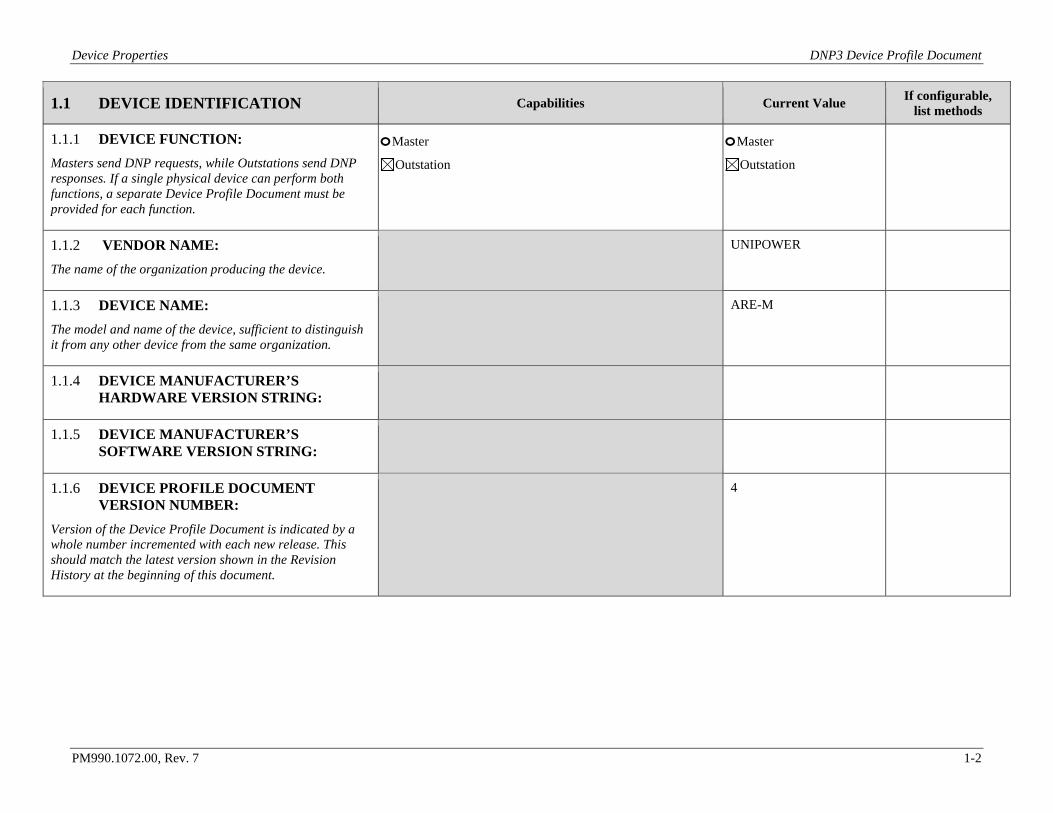
1.1 DEVICE IDENTIFICATION Capabilities Current Value If configurable, list methods
1.1.1 DEVICE FUNCTION: Masters send DNP requests, while Outstations send DNP responses. If a single physical device can perform both functions, a separate Device Profile Document must be provided for each function.
o Master Outstation
o Master Outstation
1.1.2 VENDOR NAME: The name of the organization producing the device.
UNIPOWER
1.1.3 DEVICE NAME: The model and name of the device, sufficient to distinguish it from any other device from the same organization.
ARE-M
1.1.4 DEVICE MANUFACTURER’S HARDWARE VERSION STRING:
1.1.5 DEVICE MANUFACTURER’S SOFTWARE VERSION STRING:
1.1.6 DEVICE PROFILE DOCUMENT VERSION NUMBER:
Version of the Device Profile Document is indicated by a whole number incremented with each new release. This should match the latest version shown in the Revision History at the beginning of this document.
4
Device Properties DNP3 Device Profile Document
PM990.1072.00, Rev. 7 1-3
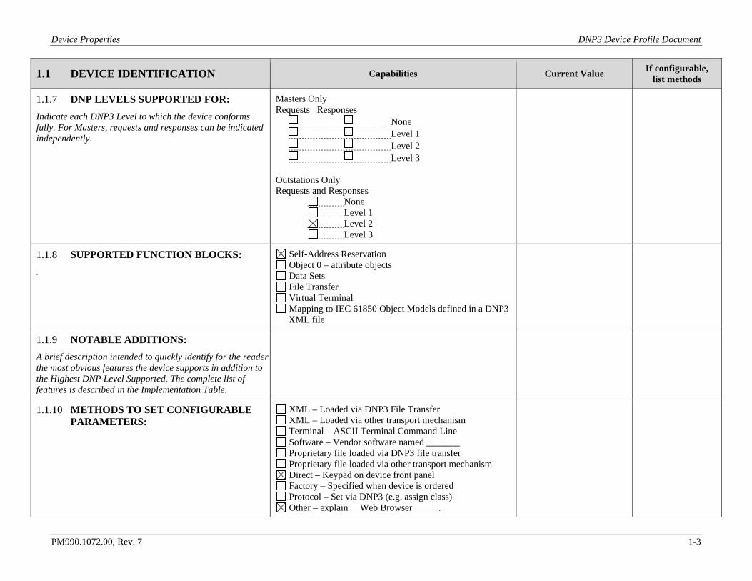
1.1 DEVICE IDENTIFICATION Capabilities Current Value If configurable, list methods
1.1.7 DNP LEVELS SUPPORTED FOR: Indicate each DNP3 Level to which the device conforms fully. For Masters, requests and responses can be indicated independently.
Masters Only Requests Responses None Level 1 Level 2 Level 3 Outstations Only Requests and Responses None Level 1 Level 2 Level 3
1.1.8 SUPPORTED FUNCTION BLOCKS: .
Self-Address Reservation Object 0 – attribute objects Data Sets File Transfer Virtual Terminal Mapping to IEC 61850 Object Models defined in a DNP3 XML file
1.1.9 NOTABLE ADDITIONS: A brief description intended to quickly identify for the reader the most obvious features the device supports in addition to the Highest DNP Level Supported. The complete list of features is described in the Implementation Table.
1.1.10 METHODS TO SET CONFIGURABLE PARAMETERS:
XML – Loaded via DNP3 File Transfer XML – Loaded via other transport mechanism Terminal – ASCII Terminal Command Line Software – Vendor software named _______ Proprietary file loaded via DNP3 file transfer Proprietary file loaded via other transport mechanism Direct – Keypad on device front panel Factory – Specified when device is ordered Protocol – Set via DNP3 (e.g. assign class) Other – explain Web Browser .
Device Properties DNP3 Device Profile Document
PM990.1072.00, Rev. 7 1-4
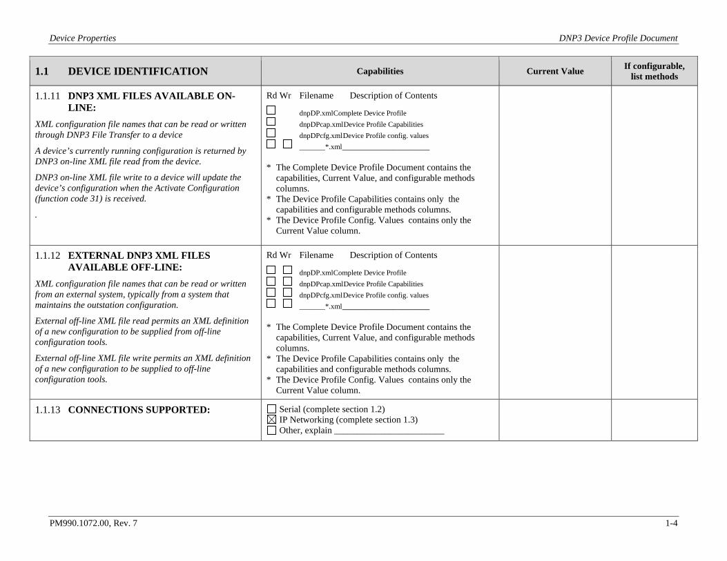
1.1 DEVICE IDENTIFICATION Capabilities Current Value If configurable, list methods
1.1.11 DNP3 XML FILES AVAILABLE ON-LINE:
XML configuration file names that can be read or written through DNP3 File Transfer to a device
A device’s currently running configuration is returned by DNP3 on-line XML file read from the device.
DNP3 on-line XML file write to a device will update the device’s configuration when the Activate Configuration (function code 31) is received.
.
Rd Wr Filename Description of Contents
dnpDP.xml Complete Device Profile dnpDPcap.xml Device Profile Capabilities dnpDPcfg.xml Device Profile config. values _______*.xml ___________________
* The Complete Device Profile Document contains the
capabilities, Current Value, and configurable methods columns.
* The Device Profile Capabilities contains only the capabilities and configurable methods columns.
* The Device Profile Config. Values contains only the Current Value column.
1.1.12 EXTERNAL DNP3 XML FILES AVAILABLE OFF-LINE:
XML configuration file names that can be read or written from an external system, typically from a system that maintains the outstation configuration.
External off-line XML file read permits an XML definition of a new configuration to be supplied from off-line configuration tools.
External off-line XML file write permits an XML definition of a new configuration to be supplied to off-line configuration tools.
Rd Wr Filename Description of Contents
dnpDP.xml Complete Device Profile dnpDPcap.xml Device Profile Capabilities dnpDPcfg.xml Device Profile config. values _______*.xml ___________________
* The Complete Device Profile Document contains the
capabilities, Current Value, and configurable methods columns.
* The Device Profile Capabilities contains only the capabilities and configurable methods columns.
* The Device Profile Config. Values contains only the Current Value column.
1.1.13 CONNECTIONS SUPPORTED:
Serial (complete section 1.2) IP Networking (complete section 1.3) Other, explain ________________________
Device Properties DNP3 Device Profile Document
PM990.1072.00, Rev. 7 1-5
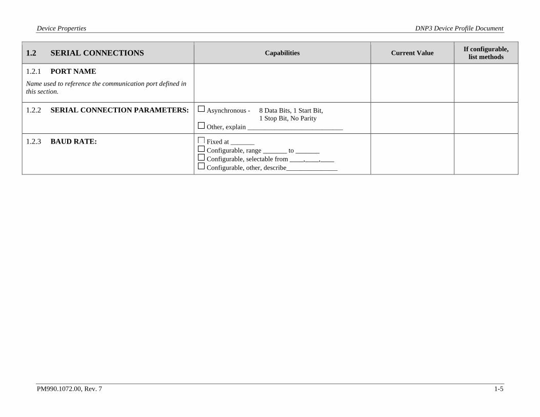
1.2 SERIAL CONNECTIONS Capabilities Current Value If configurable, list methods
1.2.1 PORT NAME Name used to reference the communication port defined in this section.
1.2.2 SERIAL CONNECTION PARAMETERS: Asynchronous - 8 Data Bits, 1 Start Bit, 1 Stop Bit, No Parity
Other, explain ____________________________
1.2.3 BAUD RATE: Fixed at _______ Configurable, range _______ to _______ Configurable, selectable from ____,____,____ Configurable, other, describe_______________
Device Properties DNP3 Device Profile Document
PM990.1072.00, Rev. 7 1-6
1.2 SERIAL CONNECTIONS Capabilities Current Value If configurable, list methods
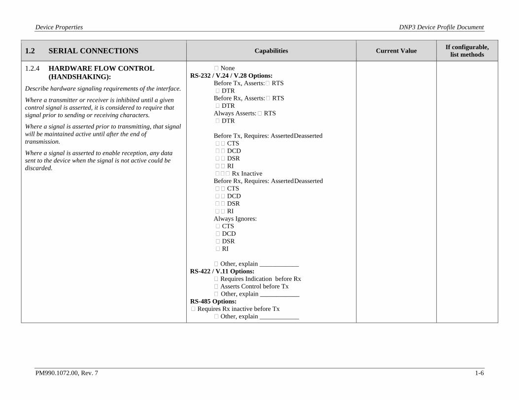
1.2.4 HARDWARE FLOW CONTROL (HANDSHAKING):
Describe hardware signaling requirements of the interface.
Where a transmitter or receiver is inhibited until a given control signal is asserted, it is considered to require that signal prior to sending or receiving characters.
Where a signal is asserted prior to transmitting, that signal will be maintained active until after the end of transmission.
Where a signal is asserted to enable reception, any data sent to the device when the signal is not active could be discarded.
None RS-232 / V.24 / V.28 Options:
Before Tx, Asserts: RTS DTR Before Rx, Asserts: RTS DTR Always Asserts: RTS DTR Before Tx, Requires: Asserted Deasserted CTS DCD DSR RI Rx Inactive Before Rx, Requires: Asserted Deasserted CTS DCD DSR RI Always Ignores: CTS DCD DSR RI Other, explain ____________
RS-422 / V.11 Options: Requires Indication before Rx Asserts Control before Tx Other, explain ____________
RS-485 Options: Requires Rx inactive before Tx
Other, explain ____________
Device Properties DNP3 Device Profile Document
PM990.1072.00, Rev. 7 1-7
1.2 SERIAL CONNECTIONS Capabilities Current Value If configurable, list methods
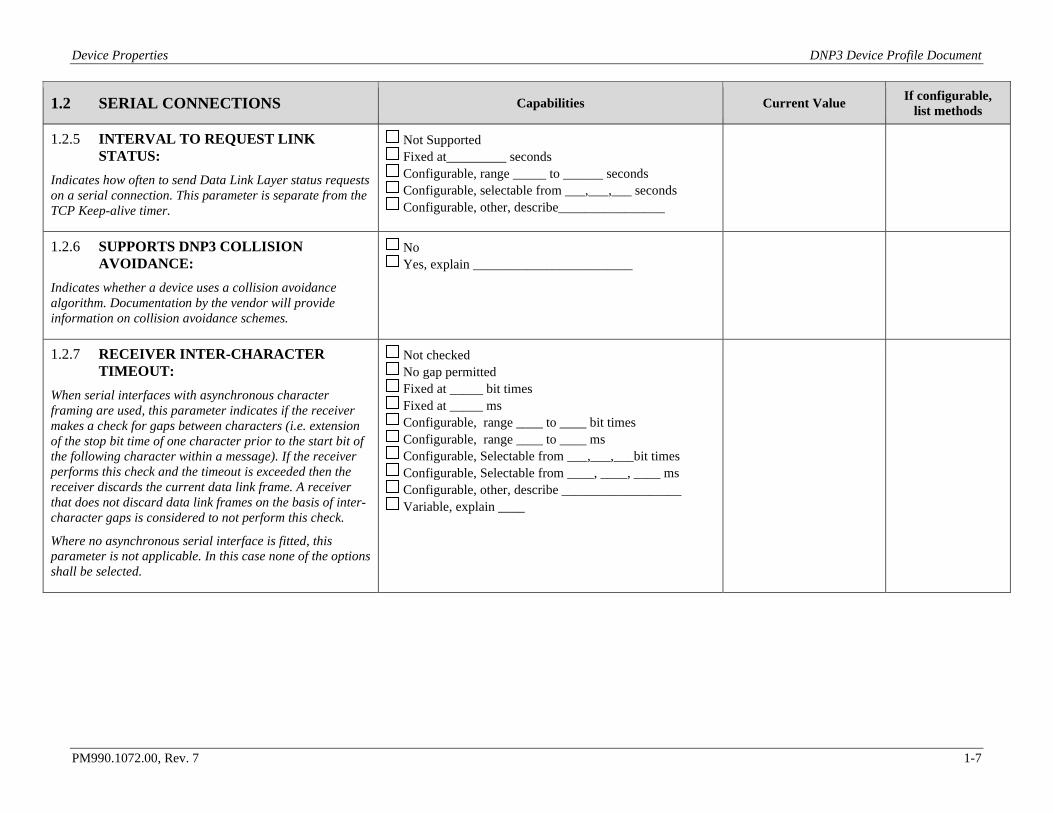
1.2.5 INTERVAL TO REQUEST LINK STATUS:
Indicates how often to send Data Link Layer status requests on a serial connection. This parameter is separate from the TCP Keep-alive timer.
Not Supported Fixed at_________ seconds Configurable, range _____ to ______ seconds Configurable, selectable from ___,___,___ seconds Configurable, other, describe________________
1.2.6 SUPPORTS DNP3 COLLISION AVOIDANCE:
Indicates whether a device uses a collision avoidance algorithm. Documentation by the vendor will provide information on collision avoidance schemes.
No Yes, explain ________________________
1.2.7 RECEIVER INTER-CHARACTER TIMEOUT:
When serial interfaces with asynchronous character framing are used, this parameter indicates if the receiver makes a check for gaps between characters (i.e. extension of the stop bit time of one character prior to the start bit of the following character within a message). If the receiver performs this check and the timeout is exceeded then the receiver discards the current data link frame. A receiver that does not discard data link frames on the basis of inter-character gaps is considered to not perform this check.
Where no asynchronous serial interface is fitted, this parameter is not applicable. In this case none of the options shall be selected.
Not checked No gap permitted Fixed at _____ bit times Fixed at _____ ms Configurable, range ____ to ____ bit times Configurable, range ____ to ____ ms Configurable, Selectable from ___,___,___bit times Configurable, Selectable from ____, ____, ____ ms Configurable, other, describe __________________ Variable, explain ____
Device Properties DNP3 Device Profile Document
PM990.1072.00, Rev. 7 1-8
1.2 SERIAL CONNECTIONS Capabilities Current Value If configurable, list methods
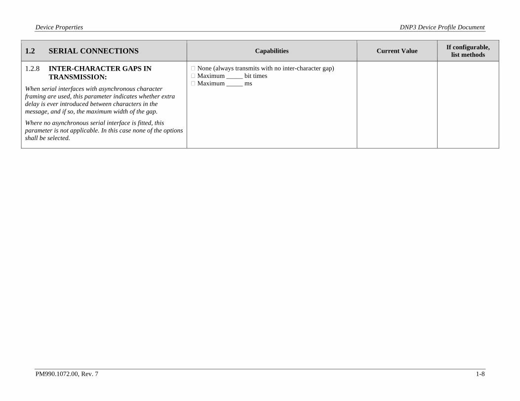
1.2.8 INTER-CHARACTER GAPS IN TRANSMISSION:
When serial interfaces with asynchronous character framing are used, this parameter indicates whether extra delay is ever introduced between characters in the message, and if so, the maximum width of the gap.
Where no asynchronous serial interface is fitted, this parameter is not applicable. In this case none of the options shall be selected.
None (always transmits with no inter-character gap) Maximum _____ bit times Maximum _____ ms
Device Properties DNP3 Device Profile Document
PM990.1072.00, Rev. 7 1-9
1.3 IP NETWORKING Capabilities Current Value If configurable, list methods
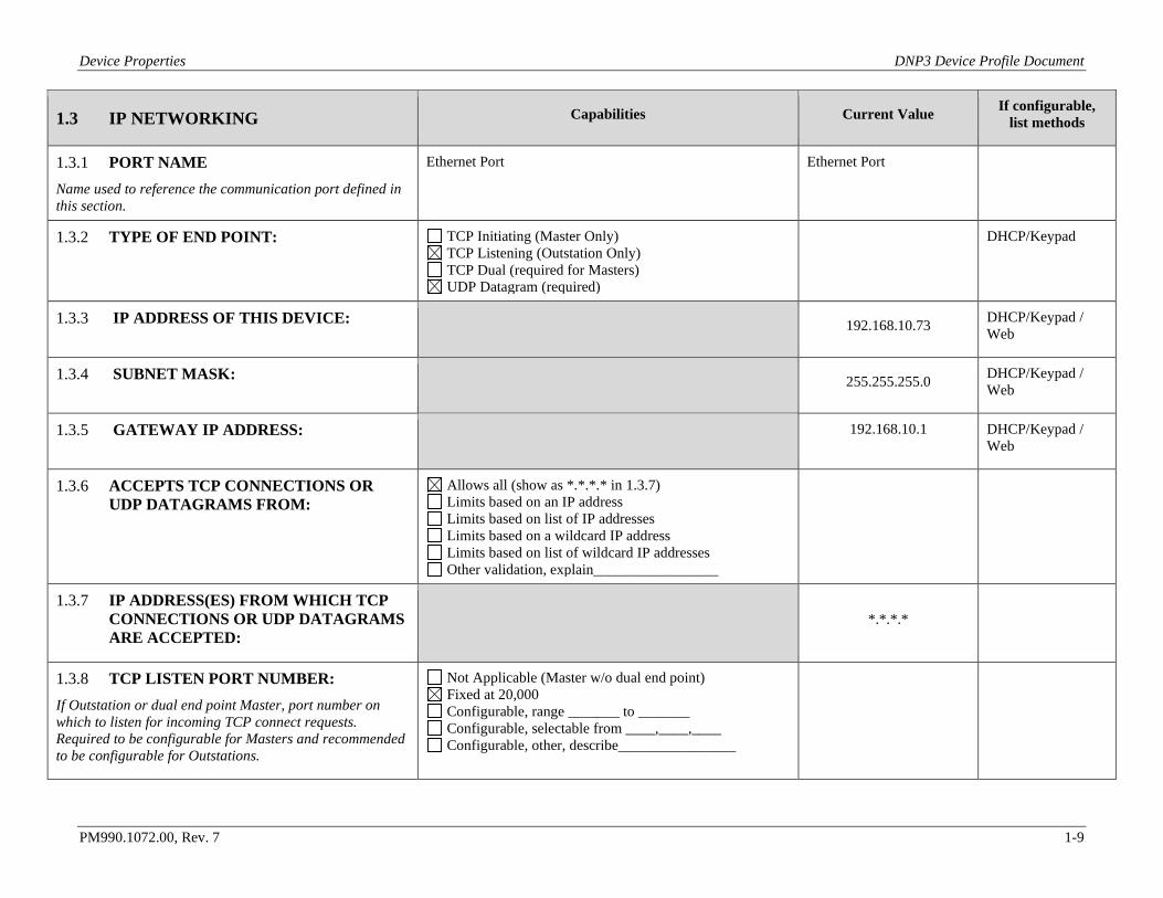
1.3.1 PORT NAME Name used to reference the communication port defined in this section.
Ethernet Port Ethernet Port
1.3.2 TYPE OF END POINT:
TCP Initiating (Master Only) TCP Listening (Outstation Only) TCP Dual (required for Masters) UDP Datagram (required)
DHCP/Keypad
1.3.3 IP ADDRESS OF THIS DEVICE: 192.168.10.73 DHCP/Keypad / Web
1.3.4 SUBNET MASK: 255.255.255.0 DHCP/Keypad / Web
1.3.5 GATEWAY IP ADDRESS: 192.168.10.1 DHCP/Keypad / Web
1.3.6 ACCEPTS TCP CONNECTIONS OR UDP DATAGRAMS FROM:
Allows all (show as *.*.*.* in 1.3.7) Limits based on an IP address Limits based on list of IP addresses Limits based on a wildcard IP address Limits based on list of wildcard IP addresses Other validation, explain_________________
1.3.7 IP ADDRESS(ES) FROM WHICH TCP CONNECTIONS OR UDP DATAGRAMS ARE ACCEPTED:
*.*.*.*
1.3.8 TCP LISTEN PORT NUMBER: If Outstation or dual end point Master, port number on which to listen for incoming TCP connect requests. Required to be configurable for Masters and recommended to be configurable for Outstations.
Not Applicable (Master w/o dual end point) Fixed at 20,000 Configurable, range _______ to _______ Configurable, selectable from ____,____,____ Configurable, other, describe________________
Device Properties DNP3 Device Profile Document
PM990.1072.00, Rev. 7 1-10
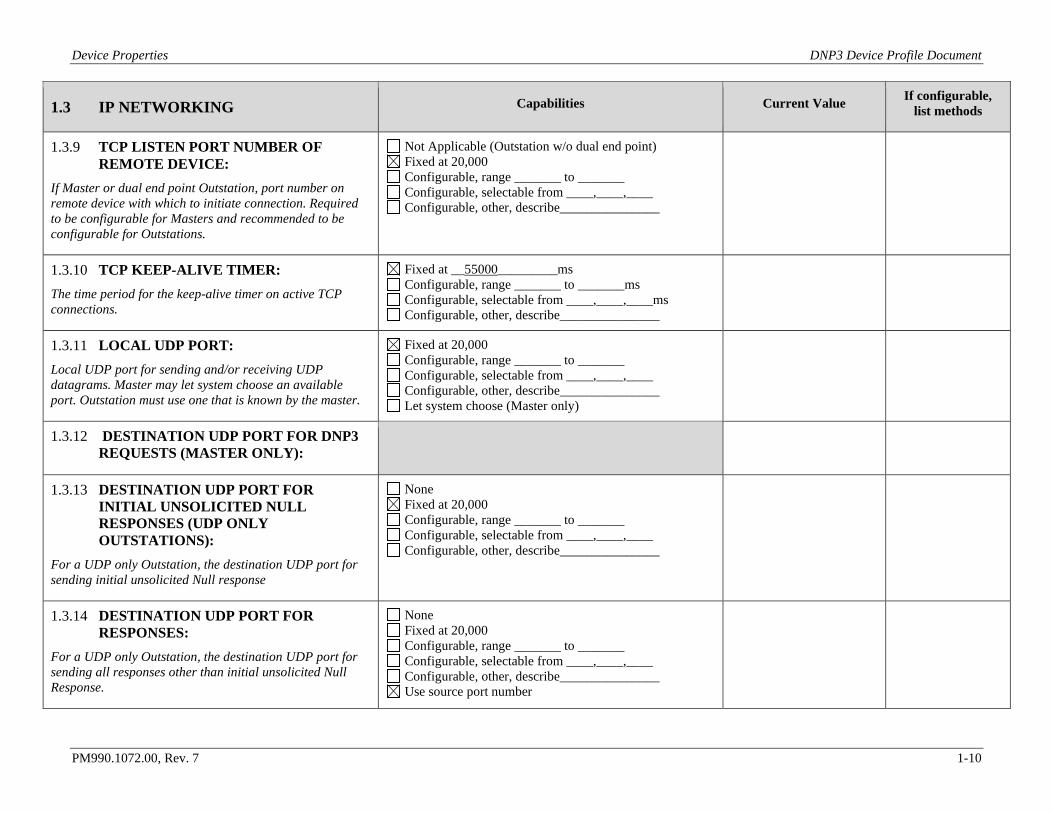
1.3 IP NETWORKING Capabilities Current Value If configurable, list methods
1.3.9 TCP LISTEN PORT NUMBER OF REMOTE DEVICE:
If Master or dual end point Outstation, port number on remote device with which to initiate connection. Required to be configurable for Masters and recommended to be configurable for Outstations.
Not Applicable (Outstation w/o dual end point) Fixed at 20,000 Configurable, range _______ to _______ Configurable, selectable from ____,____,____ Configurable, other, describe_______________
1.3.10 TCP KEEP-ALIVE TIMER: The time period for the keep-alive timer on active TCP connections.
Fixed at __55000_________ms Configurable, range _______ to _______ms Configurable, selectable from ____,____,____ms Configurable, other, describe_______________
1.3.11 LOCAL UDP PORT: Local UDP port for sending and/or receiving UDP datagrams. Master may let system choose an available port. Outstation must use one that is known by the master.
Fixed at 20,000 Configurable, range _______ to _______ Configurable, selectable from ____,____,____ Configurable, other, describe_______________ Let system choose (Master only)
1.3.12 DESTINATION UDP PORT FOR DNP3 REQUESTS (MASTER ONLY):
1.3.13 DESTINATION UDP PORT FOR INITIAL UNSOLICITED NULL RESPONSES (UDP ONLY OUTSTATIONS):
For a UDP only Outstation, the destination UDP port for sending initial unsolicited Null response
None Fixed at 20,000 Configurable, range _______ to _______ Configurable, selectable from ____,____,____ Configurable, other, describe_______________
1.3.14 DESTINATION UDP PORT FOR RESPONSES:
For a UDP only Outstation, the destination UDP port for sending all responses other than initial unsolicited Null Response.
None Fixed at 20,000 Configurable, range _______ to _______ Configurable, selectable from ____,____,____ Configurable, other, describe_______________ Use source port number
Device Properties DNP3 Device Profile Document
PM990.1072.00, Rev. 7 1-11
1.3 IP NETWORKING Capabilities Current Value If configurable, list methods
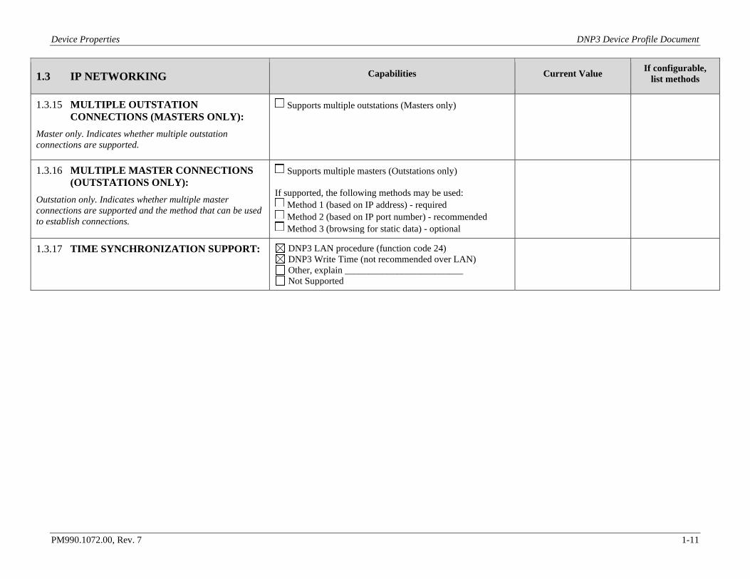
1.3.15 MULTIPLE OUTSTATION CONNECTIONS (MASTERS ONLY):
Master only. Indicates whether multiple outstation connections are supported.
Supports multiple outstations (Masters only)
1.3.16 MULTIPLE MASTER CONNECTIONS (OUTSTATIONS ONLY):
Outstation only. Indicates whether multiple master connections are supported and the method that can be used to establish connections.
Supports multiple masters (Outstations only) If supported, the following methods may be used:
Method 1 (based on IP address) - required Method 2 (based on IP port number) - recommended Method 3 (browsing for static data) - optional
1.3.17 TIME SYNCHRONIZATION SUPPORT:
DNP3 LAN procedure (function code 24) DNP3 Write Time (not recommended over LAN) Other, explain _________________________ Not Supported
Device Properties DNP3 Device Profile Document
PM990.1072.00, Rev. 7 1-12
1.4 LINK LAYER Capabilities Current Value If configurable, list methods
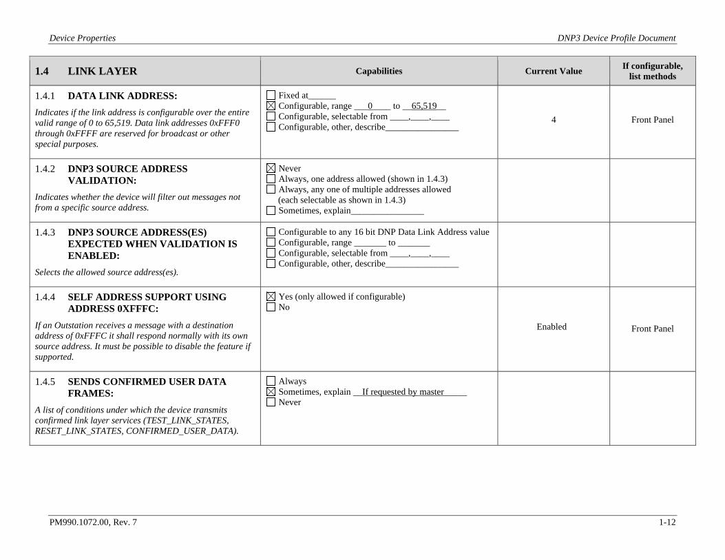
1.4.1 DATA LINK ADDRESS: Indicates if the link address is configurable over the entire valid range of 0 to 65,519. Data link addresses 0xFFF0 through 0xFFFF are reserved for broadcast or other special purposes.
Fixed at______ Configurable, range ___0____ to __65,519__ Configurable, selectable from ____,____,____ Configurable, other, describe________________
4 Front Panel
1.4.2 DNP3 SOURCE ADDRESS VALIDATION:
Indicates whether the device will filter out messages not from a specific source address.
Never Always, one address allowed (shown in 1.4.3) Always, any one of multiple addresses allowed (each selectable as shown in 1.4.3) Sometimes, explain________________
1.4.3 DNP3 SOURCE ADDRESS(ES) EXPECTED WHEN VALIDATION IS ENABLED:
Selects the allowed source address(es).
Configurable to any 16 bit DNP Data Link Address value Configurable, range _______ to _______ Configurable, selectable from ____,____,____ Configurable, other, describe________________
1.4.4 SELF ADDRESS SUPPORT USING ADDRESS 0XFFFC:
If an Outstation receives a message with a destination address of 0xFFFC it shall respond normally with its own source address. It must be possible to disable the feature if supported.
Yes (only allowed if configurable) No
Enabled
Front Panel
1.4.5 SENDS CONFIRMED USER DATA FRAMES:
A list of conditions under which the device transmits confirmed link layer services (TEST_LINK_STATES, RESET_LINK_STATES, CONFIRMED_USER_DATA).
Always Sometimes, explain __If requested by master_____ Never
Device Properties DNP3 Device Profile Document
PM990.1072.00, Rev. 7 1-13
1.4 LINK LAYER Capabilities Current Value If configurable, list methods
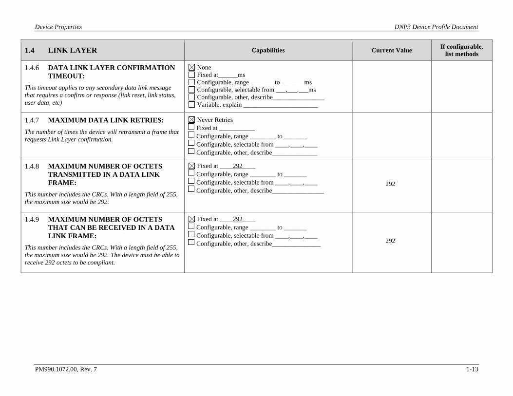
1.4.6 DATA LINK LAYER CONFIRMATION TIMEOUT:
This timeout applies to any secondary data link message that requires a confirm or response (link reset, link status, user data, etc)
None Fixed at______ms Configurable, range _______ to _______ms Configurable, selectable from ___,___,___ms Configurable, other, describe________________ Variable, explain _______________________
1.4.7 MAXIMUM DATA LINK RETRIES: The number of times the device will retransmit a frame that requests Link Layer confirmation.
Never Retries Fixed at ___________ Configurable, range ________ to _______ Configurable, selectable from ____,____,____ Configurable, other, describe______________
1.4.8 MAXIMUM NUMBER OF OCTETS TRANSMITTED IN A DATA LINK FRAME:
This number includes the CRCs. With a length field of 255, the maximum size would be 292.
Fixed at ____292____ Configurable, range ________ to _______ Configurable, selectable from ____,____,____ Configurable, other, describe________________
292
1.4.9 MAXIMUM NUMBER OF OCTETS THAT CAN BE RECEIVED IN A DATA LINK FRAME:
This number includes the CRCs. With a length field of 255, the maximum size would be 292. The device must be able to receive 292 octets to be compliant.
Fixed at ____292____ Configurable, range ________ to _______ Configurable, selectable from ____,____,____ Configurable, other, describe_______________ 292
Device Properties DNP3 Device Profile Document
PM990.1072.00, Rev. 7 1-14
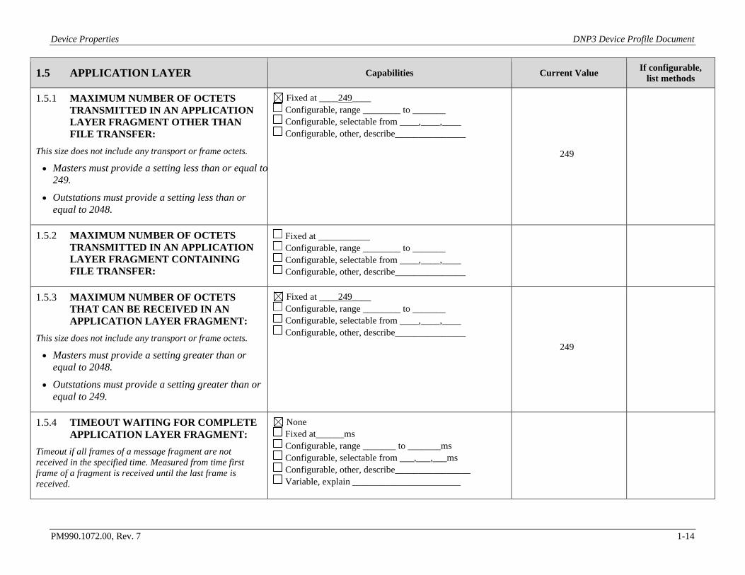
1.5 APPLICATION LAYER Capabilities Current Value If configurable, list methods
1.5.1 MAXIMUM NUMBER OF OCTETS TRANSMITTED IN AN APPLICATION LAYER FRAGMENT OTHER THAN FILE TRANSFER:
This size does not include any transport or frame octets.
• Masters must provide a setting less than or equal to 249.
• Outstations must provide a setting less than or equal to 2048.
Fixed at ____249____ Configurable, range ________ to _______ Configurable, selectable from ____,____,____ Configurable, other, describe_______________
249
1.5.2 MAXIMUM NUMBER OF OCTETS TRANSMITTED IN AN APPLICATION LAYER FRAGMENT CONTAINING FILE TRANSFER:
Fixed at ___________ Configurable, range ________ to _______ Configurable, selectable from ____,____,____ Configurable, other, describe_______________
1.5.3 MAXIMUM NUMBER OF OCTETS THAT CAN BE RECEIVED IN AN APPLICATION LAYER FRAGMENT:
This size does not include any transport or frame octets.
• Masters must provide a setting greater than or equal to 2048.
• Outstations must provide a setting greater than or equal to 249.
Fixed at ____249____ Configurable, range ________ to _______ Configurable, selectable from ____,____,____ Configurable, other, describe_______________
249
1.5.4 TIMEOUT WAITING FOR COMPLETE APPLICATION LAYER FRAGMENT:
Timeout if all frames of a message fragment are not received in the specified time. Measured from time first frame of a fragment is received until the last frame is received.
None Fixed at______ms Configurable, range _______ to _______ms Configurable, selectable from ___,___,___ms Configurable, other, describe________________ Variable, explain _______________________
Device Properties DNP3 Device Profile Document
PM990.1072.00, Rev. 7 1-15
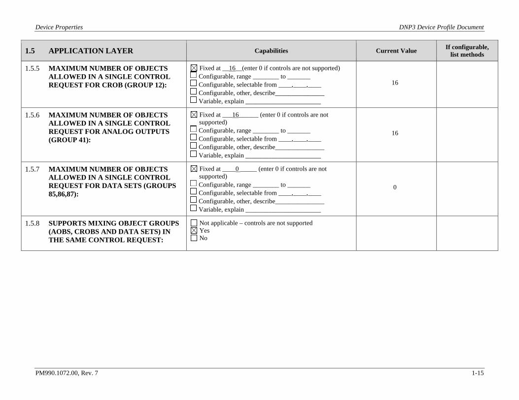
1.5 APPLICATION LAYER Capabilities Current Value If configurable, list methods
1.5.5 MAXIMUM NUMBER OF OBJECTS ALLOWED IN A SINGLE CONTROL REQUEST FOR CROB (GROUP 12):
Fixed at __16__(enter 0 if controls are not supported) Configurable, range ________ to _______ Configurable, selectable from ____,____,____ Configurable, other, describe_______________ Variable, explain _______________________
16
1.5.6 MAXIMUM NUMBER OF OBJECTS ALLOWED IN A SINGLE CONTROL REQUEST FOR ANALOG OUTPUTS (GROUP 41):
Fixed at ___16______ (enter 0 if controls are not supported)
Configurable, range ________ to _______ Configurable, selectable from ____,____,____ Configurable, other, describe_______________ Variable, explain _______________________
16
1.5.7 MAXIMUM NUMBER OF OBJECTS ALLOWED IN A SINGLE CONTROL REQUEST FOR DATA SETS (GROUPS 85,86,87):
Fixed at ____0 _____ (enter 0 if controls are not supported)
Configurable, range ________ to _______ Configurable, selectable from ____,____,____ Configurable, other, describe_______________ Variable, explain _______________________
0
1.5.8 SUPPORTS MIXING OBJECT GROUPS (AOBS, CROBS AND DATA SETS) IN THE SAME CONTROL REQUEST:
Not applicable – controls are not supported Yes No
Device Properties DNP3 Device Profile Document
PM990.1072.00, Rev. 7 1-16
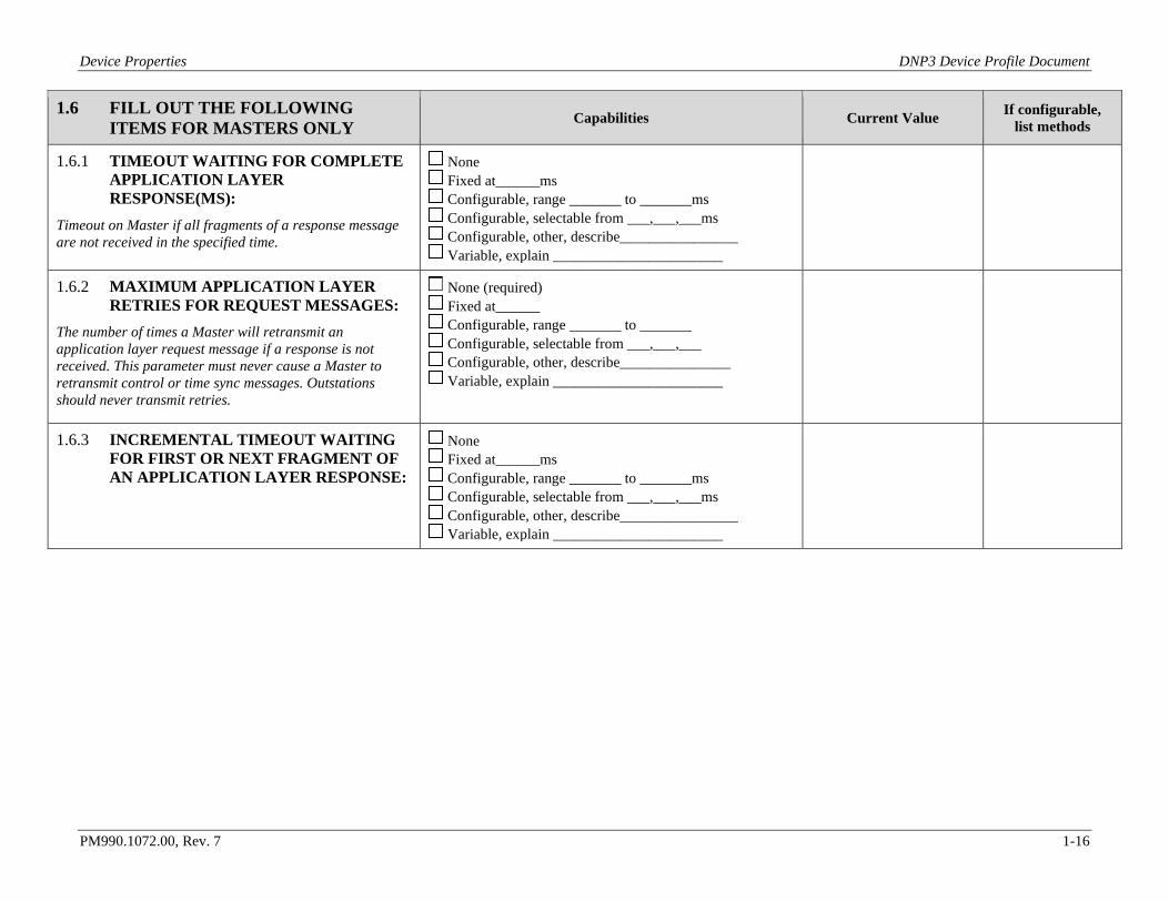
1.6 FILL OUT THE FOLLOWING ITEMS FOR MASTERS ONLY Capabilities Current Value If configurable,
list methods
1.6.1 TIMEOUT WAITING FOR COMPLETE APPLICATION LAYER RESPONSE(MS):
Timeout on Master if all fragments of a response message are not received in the specified time.
None Fixed at______ms Configurable, range _______ to _______ms Configurable, selectable from ___,___,___ms Configurable, other, describe________________ Variable, explain _______________________
1.6.2 MAXIMUM APPLICATION LAYER RETRIES FOR REQUEST MESSAGES:
The number of times a Master will retransmit an application layer request message if a response is not received. This parameter must never cause a Master to retransmit control or time sync messages. Outstations should never transmit retries.
None (required) Fixed at______ Configurable, range _______ to _______ Configurable, selectable from ___,___,___ Configurable, other, describe_______________ Variable, explain _______________________
1.6.3 INCREMENTAL TIMEOUT WAITING FOR FIRST OR NEXT FRAGMENT OF AN APPLICATION LAYER RESPONSE:
None Fixed at______ms Configurable, range _______ to _______ms Configurable, selectable from ___,___,___ms Configurable, other, describe________________ Variable, explain _______________________
Device Properties DNP3 Device Profile Document
PM990.1072.00, Rev. 7 1-17
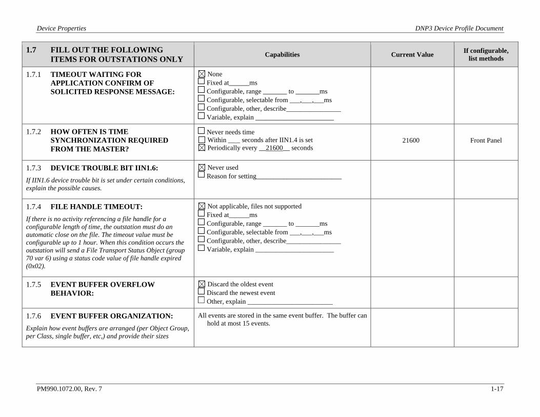
1.7 FILL OUT THE FOLLOWING ITEMS FOR OUTSTATIONS ONLY Capabilities Current Value If configurable,
list methods
1.7.1 TIMEOUT WAITING FOR APPLICATION CONFIRM OF SOLICITED RESPONSE MESSAGE:
None Fixed at______ms Configurable, range _______ to _______ms Configurable, selectable from ___,___,___ms Configurable, other, describe________________ Variable, explain _______________________
1.7.2 HOW OFTEN IS TIME SYNCHRONIZATION REQUIRED FROM THE MASTER?
Never needs time Within __ _ seconds after IIN1.4 is set Periodically every __21600__ seconds
21600 Front Panel
1.7.3 DEVICE TROUBLE BIT IIN1.6: If IIN1.6 device trouble bit is set under certain conditions, explain the possible causes.
Never used Reason for setting_________________________
1.7.4 FILE HANDLE TIMEOUT: If there is no activity referencing a file handle for a configurable length of time, the outstation must do an automatic close on the file. The timeout value must be configurable up to 1 hour. When this condition occurs the outstation will send a File Transport Status Object (group 70 var 6) using a status code value of file handle expired (0x02).
Not applicable, files not supported Fixed at______ms Configurable, range _______ to _______ms Configurable, selectable from ___,___,___ms Configurable, other, describe________________ Variable, explain _______________________
1.7.5 EVENT BUFFER OVERFLOW BEHAVIOR:
Discard the oldest event Discard the newest event Other, explain _________________________
1.7.6 EVENT BUFFER ORGANIZATION: Explain how event buffers are arranged (per Object Group, per Class, single buffer, etc,) and provide their sizes
All events are stored in the same event buffer. The buffer can hold at most 15 events.
Device Properties DNP3 Device Profile Document
PM990.1072.00, Rev. 7 1-18
1.7 FILL OUT THE FOLLOWING ITEMS FOR OUTSTATIONS ONLY Capabilities Current Value If configurable,
list methods
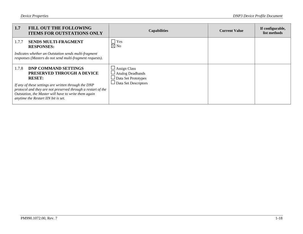
1.7.7 SENDS MULTI-FRAGMENT RESPONSES:
Indicates whether an Outstation sends multi-fragment responses (Masters do not send multi-fragment requests).
Yes No
1.7.8 DNP COMMAND SETTINGS PRESERVED THROUGH A DEVICE RESET:
If any of these settings are written through the DNP protocol and they are not preserved through a restart of the Outstation, the Master will have to write them again anytime the Restart IIN bit is set.
Assign Class Analog Deadbands Data Set Prototypes Data Set Descriptors
Device Properties DNP3 Device Profile Document
PM990.1072.00, Rev. 7 1-19
1.8 OUTSTATION UNSOLICITED RESPONSE SUPPORT Capabilities Current Value If configurable,
list methods
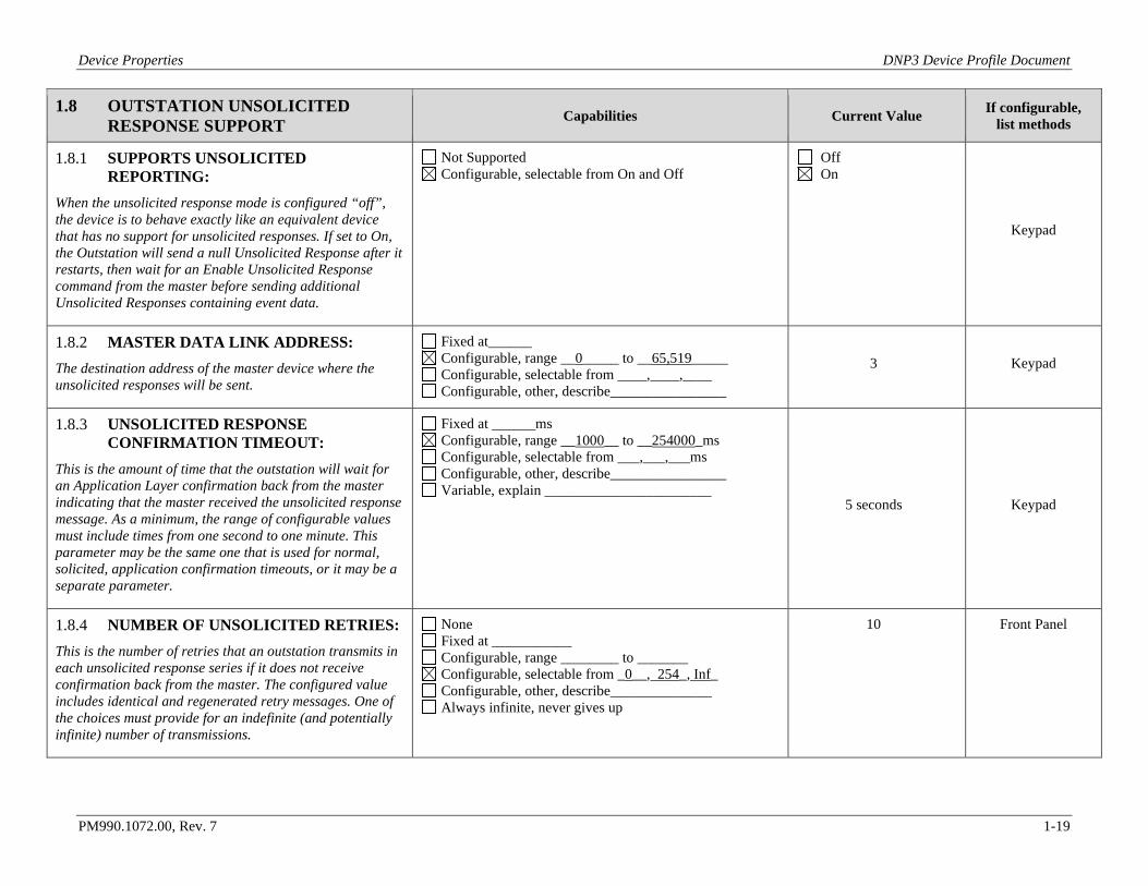
1.8.1 SUPPORTS UNSOLICITED REPORTING:
When the unsolicited response mode is configured “off”, the device is to behave exactly like an equivalent device that has no support for unsolicited responses. If set to On, the Outstation will send a null Unsolicited Response after it restarts, then wait for an Enable Unsolicited Response command from the master before sending additional Unsolicited Responses containing event data.
Not Supported Configurable, selectable from On and Off
Off On
Keypad
1.8.2 MASTER DATA LINK ADDRESS: The destination address of the master device where the unsolicited responses will be sent.
Fixed at______ Configurable, range __0_____ to __65,519_____ Configurable, selectable from ____,____,____ Configurable, other, describe________________
3 Keypad
1.8.3 UNSOLICITED RESPONSE CONFIRMATION TIMEOUT:
This is the amount of time that the outstation will wait for an Application Layer confirmation back from the master indicating that the master received the unsolicited response message. As a minimum, the range of configurable values must include times from one second to one minute. This parameter may be the same one that is used for normal, solicited, application confirmation timeouts, or it may be a separate parameter.
Fixed at ______ms Configurable, range __1000__ to __254000_ms Configurable, selectable from ___,___,___ms Configurable, other, describe________________ Variable, explain _______________________
5 seconds Keypad
1.8.4 NUMBER OF UNSOLICITED RETRIES: This is the number of retries that an outstation transmits in each unsolicited response series if it does not receive confirmation back from the master. The configured value includes identical and regenerated retry messages. One of the choices must provide for an indefinite (and potentially infinite) number of transmissions.
None Fixed at ___________ Configurable, range ________ to _______ Configurable, selectable from _0__, 254_, Inf_ Configurable, other, describe______________ Always infinite, never gives up
10 Front Panel
Device Properties DNP3 Device Profile Document
PM990.1072.00, Rev. 7 1-20
1.9 OUTSTATION UNSOLICITED RESPONSE TRIGGER CONDITIONS Capabilities Current Value If configurable,
list methods
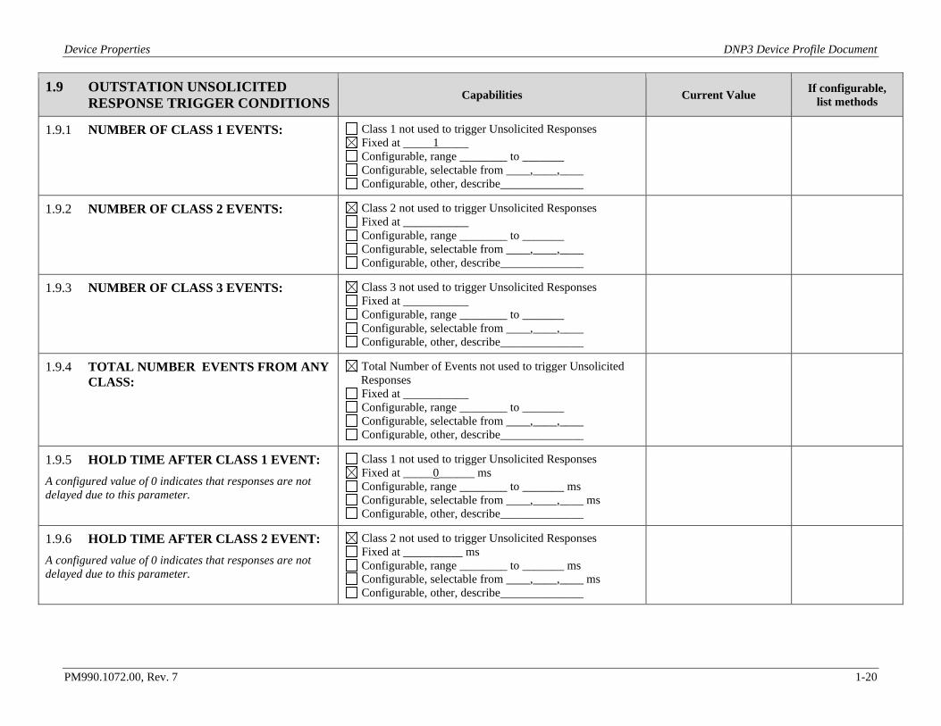
1.9.1 NUMBER OF CLASS 1 EVENTS: Class 1 not used to trigger Unsolicited Responses Fixed at _____1_____ Configurable, range ________ to _______ Configurable, selectable from ____,____,____ Configurable, other, describe______________
1.9.2 NUMBER OF CLASS 2 EVENTS: Class 2 not used to trigger Unsolicited Responses Fixed at ___________ Configurable, range ________ to _______ Configurable, selectable from ____,____,____ Configurable, other, describe______________
1.9.3 NUMBER OF CLASS 3 EVENTS: Class 3 not used to trigger Unsolicited Responses Fixed at ___________ Configurable, range ________ to _______ Configurable, selectable from ____,____,____ Configurable, other, describe______________
1.9.4 TOTAL NUMBER EVENTS FROM ANY CLASS:
Total Number of Events not used to trigger Unsolicited Responses Fixed at ___________ Configurable, range ________ to _______ Configurable, selectable from ____,____,____ Configurable, other, describe______________
1.9.5 HOLD TIME AFTER CLASS 1 EVENT: A configured value of 0 indicates that responses are not delayed due to this parameter.
Class 1 not used to trigger Unsolicited Responses Fixed at _____0______ ms Configurable, range ________ to _______ ms Configurable, selectable from ____,____,____ ms Configurable, other, describe______________
1.9.6 HOLD TIME AFTER CLASS 2 EVENT: A configured value of 0 indicates that responses are not delayed due to this parameter.
Class 2 not used to trigger Unsolicited Responses Fixed at __________ ms Configurable, range ________ to _______ ms Configurable, selectable from ____,____,____ ms Configurable, other, describe______________
Device Properties DNP3 Device Profile Document
PM990.1072.00, Rev. 7 1-21
1.9 OUTSTATION UNSOLICITED RESPONSE TRIGGER CONDITIONS Capabilities Current Value If configurable,
list methods
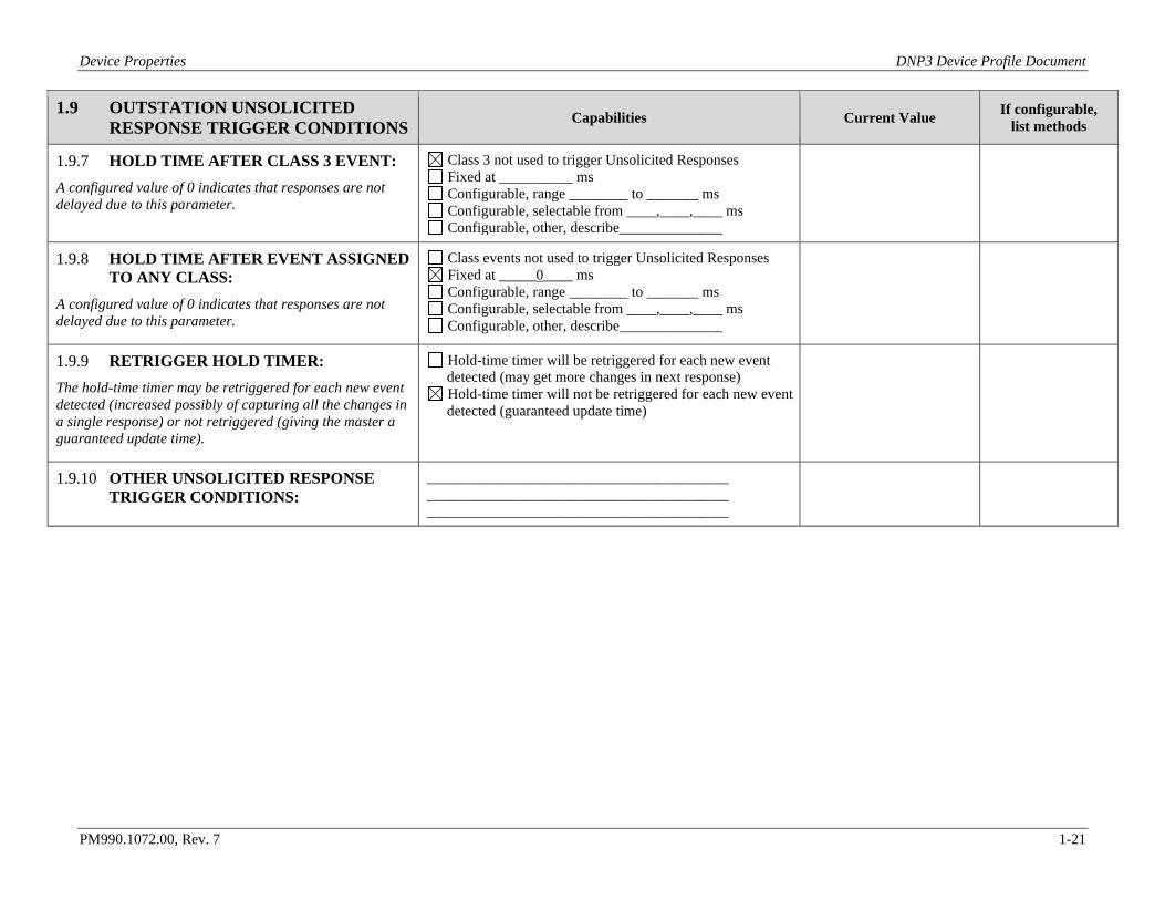
1.9.7 HOLD TIME AFTER CLASS 3 EVENT: A configured value of 0 indicates that responses are not delayed due to this parameter.
Class 3 not used to trigger Unsolicited Responses Fixed at __________ ms Configurable, range ________ to _______ ms Configurable, selectable from ____,____,____ ms Configurable, other, describe______________
1.9.8 HOLD TIME AFTER EVENT ASSIGNED TO ANY CLASS:
A configured value of 0 indicates that responses are not delayed due to this parameter.
Class events not used to trigger Unsolicited Responses Fixed at _____0____ ms Configurable, range ________ to _______ ms Configurable, selectable from ____,____,____ ms Configurable, other, describe______________
1.9.9 RETRIGGER HOLD TIMER: The hold-time timer may be retriggered for each new event detected (increased possibly of capturing all the changes in a single response) or not retriggered (giving the master a guaranteed update time).
Hold-time timer will be retriggered for each new event detected (may get more changes in next response) Hold-time timer will not be retriggered for each new event detected (guaranteed update time)
1.9.10 OTHER UNSOLICITED RESPONSE TRIGGER CONDITIONS:
_________________________________________ _________________________________________ _________________________________________
Device Properties DNP3 Device Profile Document
PM990.1072.00, Rev. 7 1-22
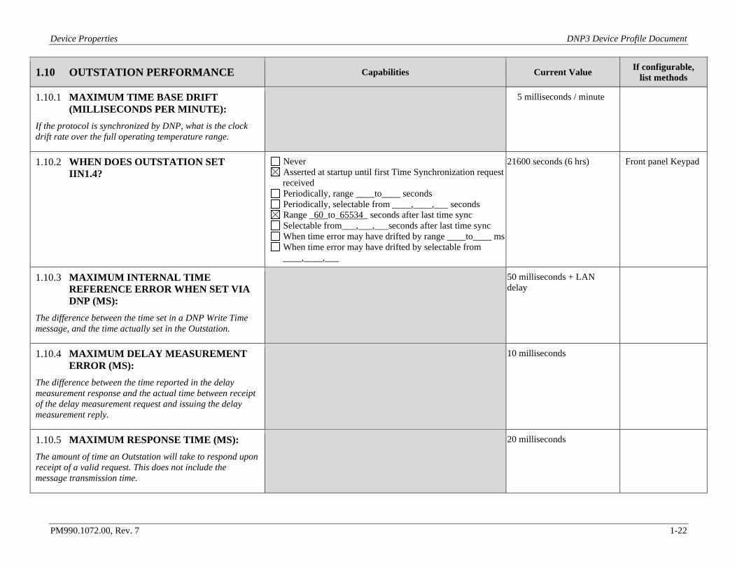
1.10 OUTSTATION PERFORMANCE Capabilities Current Value If configurable, list methods
1.10.1 MAXIMUM TIME BASE DRIFT (MILLISECONDS PER MINUTE):
If the protocol is synchronized by DNP, what is the clock drift rate over the full operating temperature range.
5 milliseconds / minute
1.10.2 WHEN DOES OUTSTATION SET IIN1.4?
Never Asserted at startup until first Time Synchronization request received Periodically, range ____to____ seconds Periodically, selectable from ____,____,___ seconds Range _60_to_65534_ seconds after last time sync Selectable from___,___,___seconds after last time sync When time error may have drifted by range ____to____ ms When time error may have drifted by selectable from ____,____,___
21600 seconds (6 hrs) Front panel Keypad
1.10.3 MAXIMUM INTERNAL TIME REFERENCE ERROR WHEN SET VIA DNP (MS):
The difference between the time set in a DNP Write Time message, and the time actually set in the Outstation.
50 milliseconds + LAN delay
1.10.4 MAXIMUM DELAY MEASUREMENT ERROR (MS):
The difference between the time reported in the delay measurement response and the actual time between receipt of the delay measurement request and issuing the delay measurement reply.
10 milliseconds
1.10.5 MAXIMUM RESPONSE TIME (MS): The amount of time an Outstation will take to respond upon receipt of a valid request. This does not include the message transmission time.
20 milliseconds
Device Properties DNP3 Device Profile Document
PM990.1072.00, Rev. 7 1-23
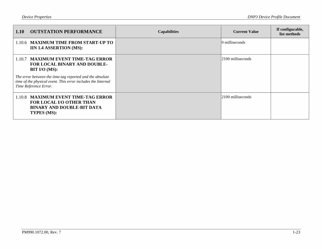
1.10 OUTSTATION PERFORMANCE Capabilities Current Value If configurable, list methods
1.10.6 MAXIMUM TIME FROM START-UP TO IIN 1.4 ASSERTION (MS):
0 milliseconds
1.10.7 MAXIMUM EVENT TIME-TAG ERROR FOR LOCAL BINARY AND DOUBLE-BIT I/O (MS):
The error between the time-tag reported and the absolute time of the physical event. This error includes the Internal Time Reference Error.
2100 milliseconds
1.10.8 MAXIMUM EVENT TIME-TAG ERROR FOR LOCAL I/O OTHER THAN BINARY AND DOUBLE-BIT DATA TYPES (MS):
2100 milliseconds
Device Properties DNP3 Device Profile Document
PM990.1072.00, Rev. 7 1-24
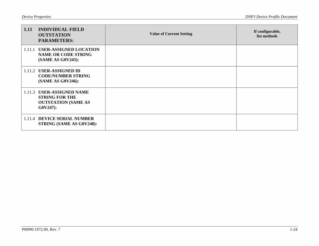
1.11 INDIVIDUAL FIELD OUTSTATION PARAMETERS:
Value of Current Setting If configurable, list methods
1.11.1 USER-ASSIGNED LOCATION NAME OR CODE STRING (SAME AS G0V245):
1.11.2 USER-ASSIGNED ID CODE/NUMBER STRING (SAME AS G0V246):
1.11.3 USER-ASSIGNED NAME STRING FOR THE OUTSTATION (SAME AS G0V247):
1.11.4 DEVICE SERIAL NUMBER STRING (SAME AS G0V248):
Mapping to IEC 61850 Object Models DNP3 Device Profile Document
PM990.1072.00, Rev. 7 2-1
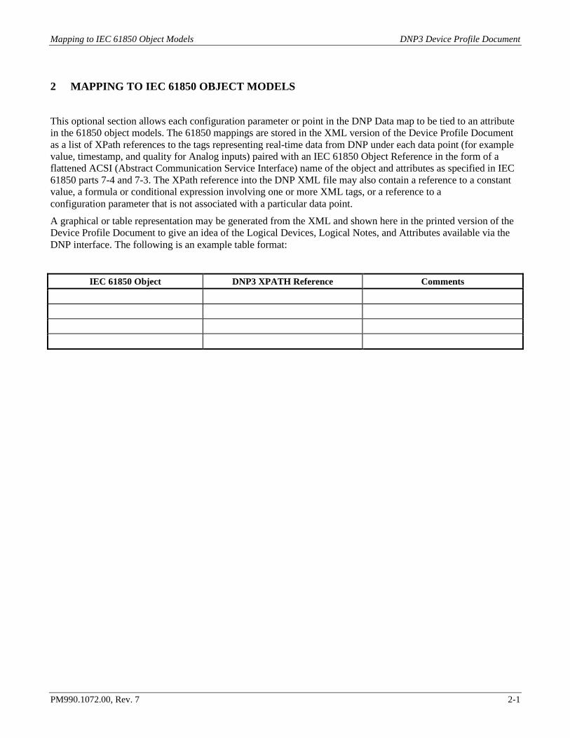
2 MAPPING TO IEC 61850 OBJECT MODELS
This optional section allows each configuration parameter or point in the DNP Data map to be tied to an attribute in the 61850 object models. The 61850 mappings are stored in the XML version of the Device Profile Document as a list of XPath references to the tags representing real-time data from DNP under each data point (for example value, timestamp, and quality for Analog inputs) paired with an IEC 61850 Object Reference in the form of a flattened ACSI (Abstract Communication Service Interface) name of the object and attributes as specified in IEC 61850 parts 7-4 and 7-3. The XPath reference into the DNP XML file may also contain a reference to a constant value, a formula or conditional expression involving one or more XML tags, or a reference to a configuration parameter that is not associated with a particular data point.
A graphical or table representation may be generated from the XML and shown here in the printed version of the Device Profile Document to give an idea of the Logical Devices, Logical Notes, and Attributes available via the DNP interface. The following is an example table format:
IEC 61850 Object DNP3 XPATH Reference Comments

Capabilities and Current Settings for Device Database (Outstation Only) DNP3 Device Profile Document
PM990.1072.00, Rev. 7 3-1
3 CAPABILITIES AND CURRENT SETTINGS FOR DEVICE DATABASE (OUTSTATION ONLY)
The following tables identify the capabilities and current settings for each DNP3 data type. Each data type also provides a table defining the data points available in the device or a description of how this information can be obtained if the database is configurable. Tables for data types not supported may be deleted. Additional columns may be added to the point list table if necessary.
Capabilities and Current Settings for Device Database (Outstation Only) DNP3 Device Profile Document
PM990.1072.00, Rev. 7 3-2
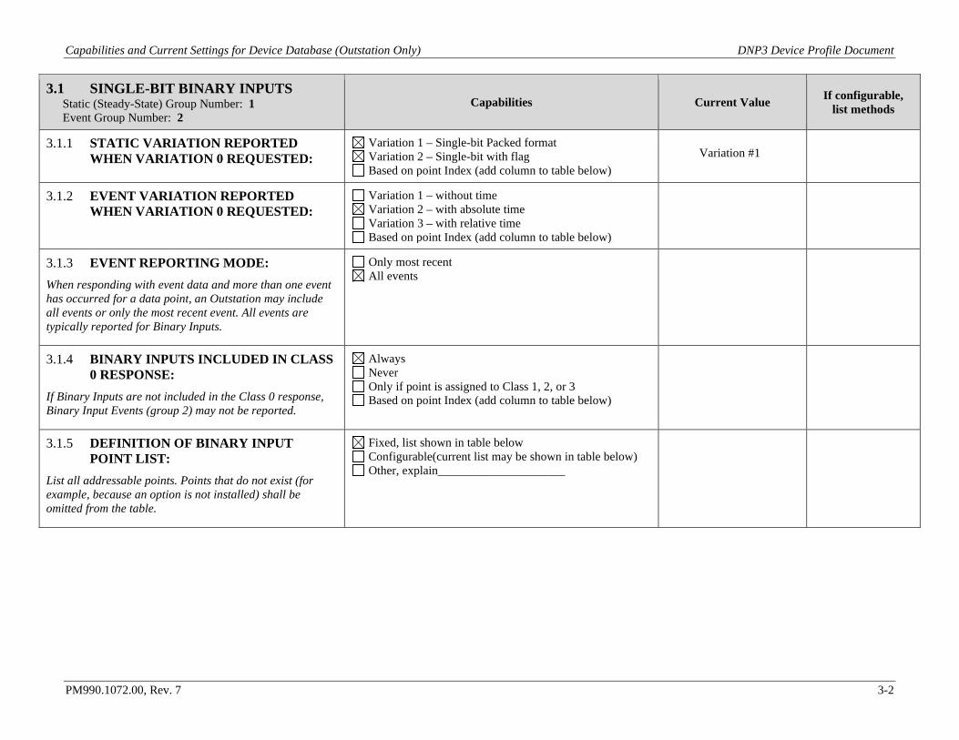
3.1 SINGLE-BIT BINARY INPUTS Static (Steady-State) Group Number: 1 Event Group Number: 2
Capabilities Current Value If configurable, list methods
3.1.1 STATIC VARIATION REPORTED WHEN VARIATION 0 REQUESTED:
Variation 1 – Single-bit Packed format Variation 2 – Single-bit with flag Based on point Index (add column to table below)
Variation #1
3.1.2 EVENT VARIATION REPORTED WHEN VARIATION 0 REQUESTED:
Variation 1 – without time Variation 2 – with absolute time Variation 3 – with relative time Based on point Index (add column to table below)
3.1.3 EVENT REPORTING MODE: When responding with event data and more than one event has occurred for a data point, an Outstation may include all events or only the most recent event. All events are typically reported for Binary Inputs.
Only most recent All events
3.1.4 BINARY INPUTS INCLUDED IN CLASS 0 RESPONSE:
If Binary Inputs are not included in the Class 0 response, Binary Input Events (group 2) may not be reported.
Always Never Only if point is assigned to Class 1, 2, or 3 Based on point Index (add column to table below)
3.1.5 DEFINITION OF BINARY INPUT POINT LIST:
List all addressable points. Points that do not exist (for example, because an option is not installed) shall be omitted from the table.
Fixed, list shown in table below Configurable(current list may be shown in table below) Other, explain_____________________
Capabilities and Current Settings for Device Database (Outstation Only) DNP3 Device Profile Document
PM990.1072.00, Rev. 7 3-3
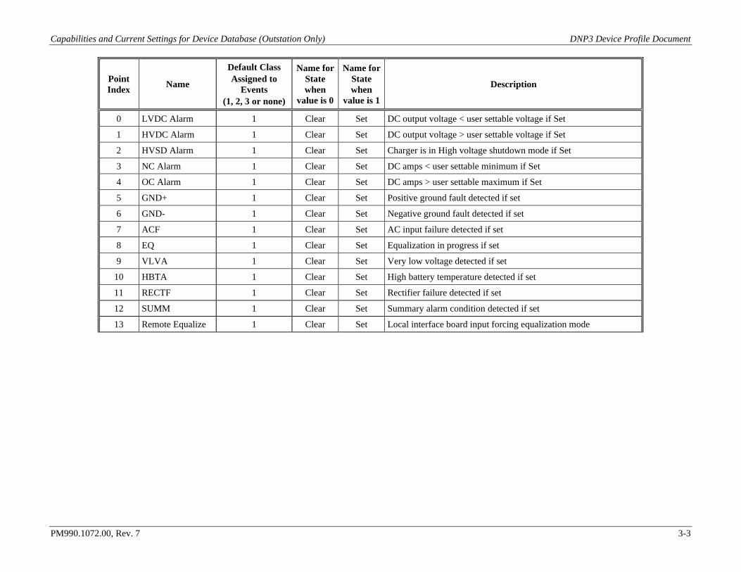
Point Index Name
Default Class Assigned to
Events (1, 2, 3 or none)
Name for State when
value is 0
Name for State when
value is 1
Description
0 LVDC Alarm 1 Clear Set DC output voltage < user settable voltage if Set
1 HVDC Alarm 1 Clear Set DC output voltage > user settable voltage if Set
2 HVSD Alarm 1 Clear Set Charger is in High voltage shutdown mode if Set
3 NC Alarm 1 Clear Set DC amps < user settable minimum if Set
4 OC Alarm 1 Clear Set DC amps > user settable maximum if Set
5 GND+ 1 Clear Set Positive ground fault detected if set
6 GND- 1 Clear Set Negative ground fault detected if set
7 ACF 1 Clear Set AC input failure detected if set
8 EQ 1 Clear Set Equalization in progress if set
9 VLVA 1 Clear Set Very low voltage detected if set
10 HBTA 1 Clear Set High battery temperature detected if set
11 RECTF 1 Clear Set Rectifier failure detected if set
12 SUMM 1 Clear Set Summary alarm condition detected if set
13 Remote Equalize 1 Clear Set Local interface board input forcing equalization mode
Capabilities and Current Settings for Device Database (Outstation Only) DNP3 Device Profile Document
PM990.1072.00, Rev. 7 3-4
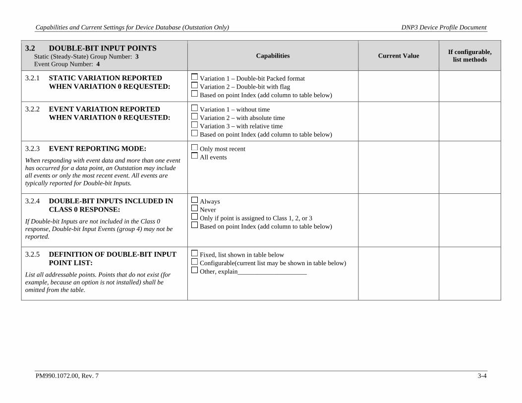
3.2 DOUBLE-BIT INPUT POINTS Static (Steady-State) Group Number: 3 Event Group Number: 4
Capabilities Current Value If configurable, list methods
3.2.1 STATIC VARIATION REPORTED WHEN VARIATION 0 REQUESTED:
Variation 1 – Double-bit Packed format Variation 2 – Double-bit with flag Based on point Index (add column to table below)
3.2.2 EVENT VARIATION REPORTED WHEN VARIATION 0 REQUESTED:
Variation 1 – without time Variation 2 – with absolute time Variation 3 – with relative time Based on point Index (add column to table below)
3.2.3 EVENT REPORTING MODE: When responding with event data and more than one event has occurred for a data point, an Outstation may include all events or only the most recent event. All events are typically reported for Double-bit Inputs.
Only most recent All events
3.2.4 DOUBLE-BIT INPUTS INCLUDED IN CLASS 0 RESPONSE:
If Double-bit Inputs are not included in the Class 0 response, Double-bit Input Events (group 4) may not be reported.
Always Never Only if point is assigned to Class 1, 2, or 3 Based on point Index (add column to table below)
3.2.5 DEFINITION OF DOUBLE-BIT INPUT POINT LIST:
List all addressable points. Points that do not exist (for example, because an option is not installed) shall be omitted from the table.
Fixed, list shown in table below Configurable(current list may be shown in table below) Other, explain_____________________
Capabilities and Current Settings for Device Database (Outstation Only) DNP3 Device Profile Document
PM990.1072.00, Rev. 7 3-5
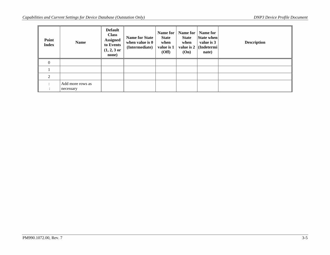
Point Index Name
Default Class
Assigned to Events (1, 2, 3 or
none)
Name for State when value is 0 (Intermediate)
Name for State when
value is 1 (Off)
Name for State when
value is 2 (On)
Name for State when value is 3
(Indeterminate)
Description
0
1
2
: :
Add more rows as necessary
Capabilities and Current Settings for Device Database (Outstation Only) DNP3 Device Profile Document
PM990.1072.00, Rev. 7 3-6
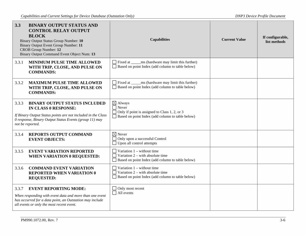
3.3 BINARY OUTPUT STATUS AND CONTROL RELAY OUTPUT BLOCK
Binary Output Status Group Number: 10 Binary Output Event Group Number: 11 CROB Group Number: 12 Binary Output Command Event Object Num: 13
Capabilities Current Value If configurable, list methods
3.3.1 MINIMUM PULSE TIME ALLOWED WITH TRIP, CLOSE, AND PULSE ON COMMANDS:
Fixed at _____ms (hardware may limit this further) Based on point Index (add column to table below)
3.3.2 MAXIMUM PULSE TIME ALLOWED WITH TRIP, CLOSE, AND PULSE ON COMMANDS:
Fixed at _____ms (hardware may limit this further) Based on point Index (add column to table below)
3.3.3 BINARY OUTPUT STATUS INCLUDED IN CLASS 0 RESPONSE:
If Binary Output Status points are not included in the Class 0 response, Binary Output Status Events (group 11) may not be reported.
Always Never Only if point is assigned to Class 1, 2, or 3 Based on point Index (add column to table below)
3.3.4 REPORTS OUTPUT COMMAND EVENT OBJECTS:
Never Only upon a successful Control Upon all control attempts
3.3.5 EVENT VARIATION REPORTED WHEN VARIATION 0 REQUESTED:
Variation 1 – without time Variation 2 – with absolute time Based on point Index (add column to table below)
3.3.6 COMMAND EVENT VARIATION REPORTED WHEN VARIATION 0 REQUESTED:
Variation 1 – without time Variation 2 – with absolute time Based on point Index (add column to table below)
3.3.7 EVENT REPORTING MODE: When responding with event data and more than one event has occurred for a data point, an Outstation may include all events or only the most recent event.
Only most recent All events
Capabilities and Current Settings for Device Database (Outstation Only) DNP3 Device Profile Document
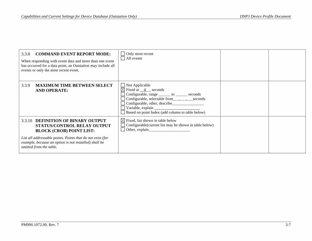
PM990.1072.00, Rev. 7 3-7
3.3.8 COMMAND EVENT REPORT MODE: When responding with event data and more than one event has occurred for a data point, an Outstation may include all events or only the most recent event.
Only most recent All events
3.3.9 MAXIMUM TIME BETWEEN SELECT AND OPERATE:
Not Applicable Fixed at __4 __ seconds Configurable, range ______ to ______ seconds Configurable, selectable from___,___,___seconds Configurable, other, describe________________ Variable, explain _______________________ Based on point Index (add column to table below)
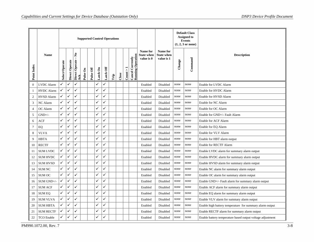
3.3.10 DEFINITION OF BINARY OUTPUT STATUS/CONTROL RELAY OUTPUT BLOCK (CROB) POINT LIST:
List all addressable points. Points that do not exist (for example, because an option is not installed) shall be omitted from the table.
Fixed, list shown in table below Configurable(current list may be shown in table below) Other, explain_____________________
Capabilities and Current Settings for Device Database (Outstation Only) DNP3 Device Profile Document
PM990.1072.00, Rev. 7 3-8
Poin
t Ind
ex
Name
Supported Control Operations
Name for State when value is 0
Name for State when value is 1
Default Class Assigned to
Events (1, 2, 3 or none)
Description
Sele
ct/O
pera
te
Dir
ect O
pera
te
Dir
ect O
pera
te –
No
Ack
Puls
e O
n
Puls
e O
ff
Lat
ch O
n
Lat
ch O
ff
Tri
p
Clo
se
Cou
nt >
1
Can
cel C
urre
ntly
R
unni
ng O
pera
tion
Cha
nge
Com
man
d
0 LVDC Alarm Enabled Disabled none none Enable for LVDC Alarm
1 HVDC Alarm Enabled Disabled none none Enable for HVDC Alarm
2 HVSD Alarm Enabled Disabled none none Enable for HVSD Alarm
3 NC Alarm Enabled Disabled none none Enable for NC Alarm
4 OC Alarm Enabled Disabled none none Enable for OC Alarm
5 GND+/- Enabled Disabled none none Enable for GND+/- Fault Alarm
6 ACF Enabled Disabled none none Enable for ACF Alarm
7 EQ Enabled Disabled none none Enable for EQ Alarm
8 VLVA Enabled Disabled none none Enable for VLV Alarm
9 HBTA Enabled Disabled none none Enable for HBT alarm output
10 RECTF Enabled Disabled none none Enable for RECTF Alarm
11 SUM LVDC Enabled Disabled none none Enable LVDC alarm for summary alarm output
12 SUM HVDC Enabled Disabled none none Enable HVDC alarm for summary alarm output
13 SUM HVSD Enabled Disabled none none Enable HVSD alarm for summary alarm output
14 SUM NC Enabled Disabled none none Enable NC alarm for summary alarm output
15 SUM OC Enabled Disabled none none Enable OC alarm for summary alarm output
16 SUM GND+/- Enabled Disabled none none Enable GND+/- Fault alarm for summary alarm output
17 SUM ACF Enabled Disabled none none Enable ACF alarm for summary alarm output
18 SUM EQ Enabled Disabled none none Enable EQ alarm for summary alarm output
19 SUM VLVA Enabled Disabled none none Enable VLV alarm for summary alarm output
20 SUM HBTA Enabled Disabled none none Enable high battery temperature for summary alarm output
21 SUM RECTF Enabled Disabled none none Enable RECTF alarm for summary alarm output
22 TCO Enable Enabled Disabled none none Enable battery temperature based output voltage adjustment
Capabilities and Current Settings for Device Database (Outstation Only) DNP3 Device Profile Document
PM990.1072.00, Rev. 7 3-9
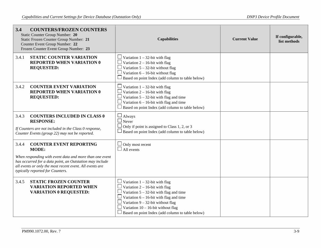
3.4 COUNTERS/FROZEN COUNTERS Static Counter Group Number: 20 Static Frozen Counter Group Number: 21 Counter Event Group Number: 22 Frozen Counter Event Group Number: 23
Capabilities Current Value If configurable, list methods
3.4.1 STATIC COUNTER VARIATION REPORTED WHEN VARIATION 0 REQUESTED:
Variation 1 – 32-bit with flag Variation 2 – 16-bit with flag Variation 5 – 32-bit without flag Variation 6 – 16-bit without flag Based on point Index (add column to table below)
3.4.2 COUNTER EVENT VARIATION REPORTED WHEN VARIATION 0 REQUESTED:
Variation 1 – 32-bit with flag Variation 2 – 16-bit with flag Variation 5 – 32-bit with flag and time Variation 6 – 16-bit with flag and time Based on point Index (add column to table below)
3.4.3 COUNTERS INCLUDED IN CLASS 0 RESPONSE:
If Counters are not included in the Class 0 response, Counter Events (group 22) may not be reported.
Always Never Only if point is assigned to Class 1, 2, or 3 Based on point Index (add column to table below)
3.4.4 COUNTER EVENT REPORTING MODE:
When responding with event data and more than one event has occurred for a data point, an Outstation may include all events or only the most recent event. All events are typically reported for Counters.
Only most recent All events
3.4.5 STATIC FROZEN COUNTER VARIATION REPORTED WHEN VARIATION 0 REQUESTED:
Variation 1 – 32-bit with flag Variation 2 – 16-bit with flag Variation 5 – 32-bit with flag and time Variation 6 – 16-bit with flag and time Variation 9 – 32-bit without flag Variation 10 – 16-bit without flag Based on point Index (add column to table below)
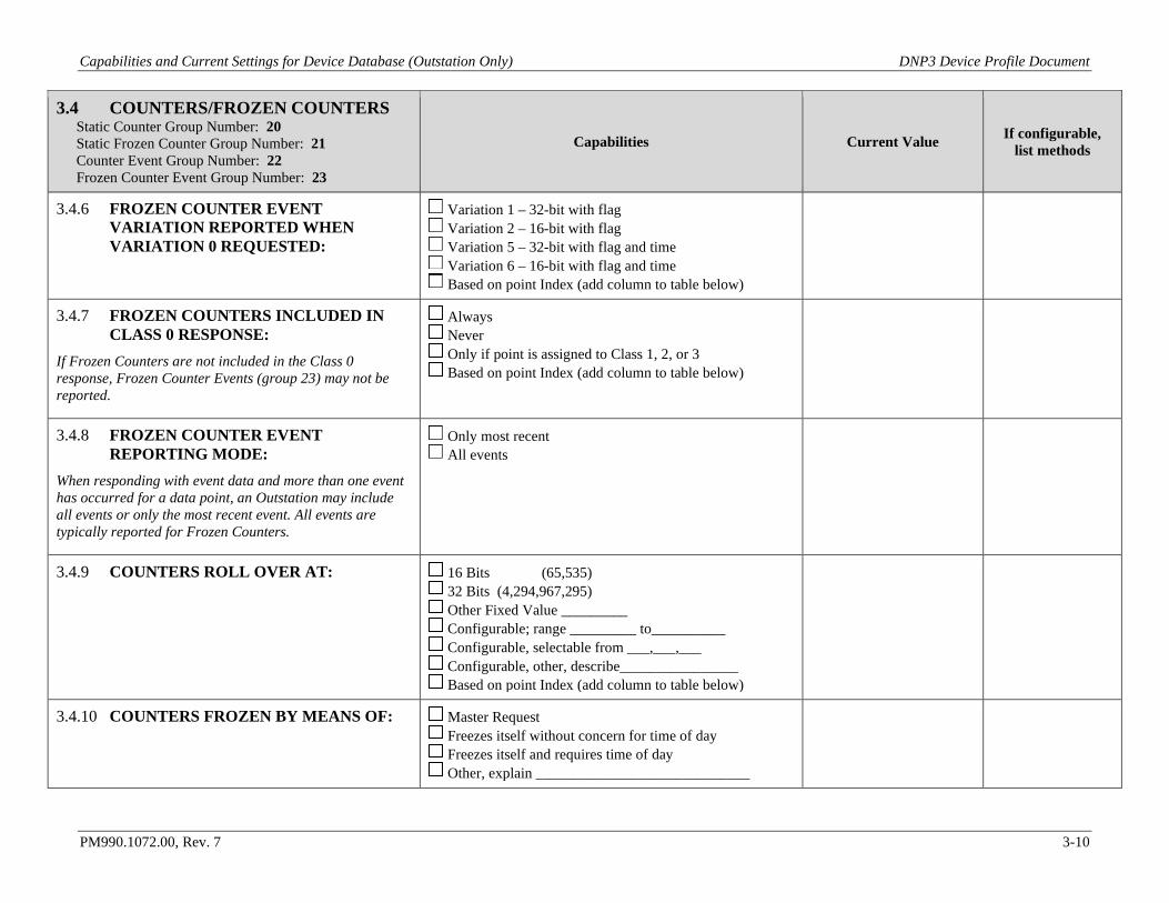
Capabilities and Current Settings for Device Database (Outstation Only) DNP3 Device Profile Document
PM990.1072.00, Rev. 7 3-10
3.4 COUNTERS/FROZEN COUNTERS Static Counter Group Number: 20 Static Frozen Counter Group Number: 21 Counter Event Group Number: 22 Frozen Counter Event Group Number: 23
Capabilities Current Value If configurable, list methods
3.4.6 FROZEN COUNTER EVENT VARIATION REPORTED WHEN VARIATION 0 REQUESTED:
Variation 1 – 32-bit with flag Variation 2 – 16-bit with flag Variation 5 – 32-bit with flag and time Variation 6 – 16-bit with flag and time Based on point Index (add column to table below)
3.4.7 FROZEN COUNTERS INCLUDED IN CLASS 0 RESPONSE:
If Frozen Counters are not included in the Class 0 response, Frozen Counter Events (group 23) may not be reported.
Always Never Only if point is assigned to Class 1, 2, or 3 Based on point Index (add column to table below)
3.4.8 FROZEN COUNTER EVENT REPORTING MODE:
When responding with event data and more than one event has occurred for a data point, an Outstation may include all events or only the most recent event. All events are typically reported for Frozen Counters.
Only most recent All events
3.4.9 COUNTERS ROLL OVER AT: 16 Bits (65,535) 32 Bits (4,294,967,295) Other Fixed Value _________ Configurable; range _________ to__________ Configurable, selectable from ___,___,___ Configurable, other, describe________________ Based on point Index (add column to table below)
3.4.10 COUNTERS FROZEN BY MEANS OF: Master Request Freezes itself without concern for time of day Freezes itself and requires time of day Other, explain _____________________________

Capabilities and Current Settings for Device Database (Outstation Only) DNP3 Device Profile Document
PM990.1072.00, Rev. 7 3-11
3.4 COUNTERS/FROZEN COUNTERS Static Counter Group Number: 20 Static Frozen Counter Group Number: 21 Counter Event Group Number: 22 Frozen Counter Event Group Number: 23
Capabilities Current Value If configurable, list methods
3.4.11 DEFINITION OF COUNTER/FROZEN COUNTER POINT LIST:
List all addressable points. Points that do not exist (for example, because an option is not installed) shall be omitted from the table.
Fixed, list shown in table below Configurable(current list may be shown in table below) Other, explain_____________________
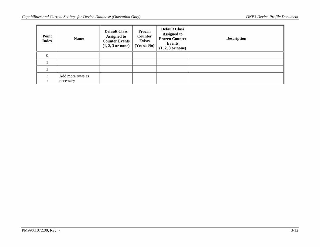
Capabilities and Current Settings for Device Database (Outstation Only) DNP3 Device Profile Document
PM990.1072.00, Rev. 7 3-12
Point Index Name
Default Class Assigned to
Counter Events (1, 2, 3 or none)
Frozen Counter
Exists (Yes or No)
Default Class Assigned to
Frozen Counter Events
(1, 2, 3 or none)
Description
0
1
2
: :
Add more rows as necessary
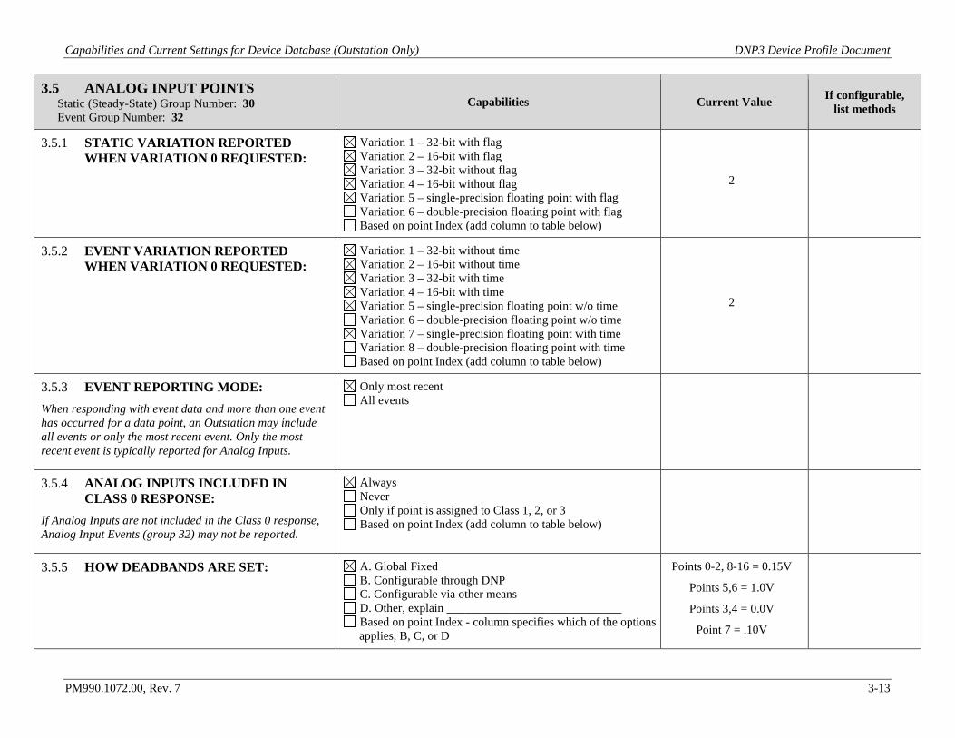
Capabilities and Current Settings for Device Database (Outstation Only) DNP3 Device Profile Document
PM990.1072.00, Rev. 7 3-13
3.5 ANALOG INPUT POINTS Static (Steady-State) Group Number: 30 Event Group Number: 32
Capabilities Current Value If configurable, list methods
3.5.1 STATIC VARIATION REPORTED WHEN VARIATION 0 REQUESTED:
Variation 1 – 32-bit with flag Variation 2 – 16-bit with flag Variation 3 – 32-bit without flag Variation 4 – 16-bit without flag Variation 5 – single-precision floating point with flag Variation 6 – double-precision floating point with flag Based on point Index (add column to table below)
2
3.5.2 EVENT VARIATION REPORTED WHEN VARIATION 0 REQUESTED:
Variation 1 – 32-bit without time Variation 2 – 16-bit without time Variation 3 – 32-bit with time Variation 4 – 16-bit with time Variation 5 – single-precision floating point w/o time Variation 6 – double-precision floating point w/o time Variation 7 – single-precision floating point with time Variation 8 – double-precision floating point with time Based on point Index (add column to table below)
2
3.5.3 EVENT REPORTING MODE: When responding with event data and more than one event has occurred for a data point, an Outstation may include all events or only the most recent event. Only the most recent event is typically reported for Analog Inputs.
Only most recent All events
3.5.4 ANALOG INPUTS INCLUDED IN CLASS 0 RESPONSE:
If Analog Inputs are not included in the Class 0 response, Analog Input Events (group 32) may not be reported.
Always Never Only if point is assigned to Class 1, 2, or 3 Based on point Index (add column to table below)
3.5.5 HOW DEADBANDS ARE SET: A. Global Fixed B. Configurable through DNP C. Configurable via other means D. Other, explain _____________________________ Based on point Index - column specifies which of the options applies, B, C, or D
Points 0-2, 8-16 = 0.15V
Points 5,6 = 1.0V
Points 3,4 = 0.0V
Point 7 = .10V
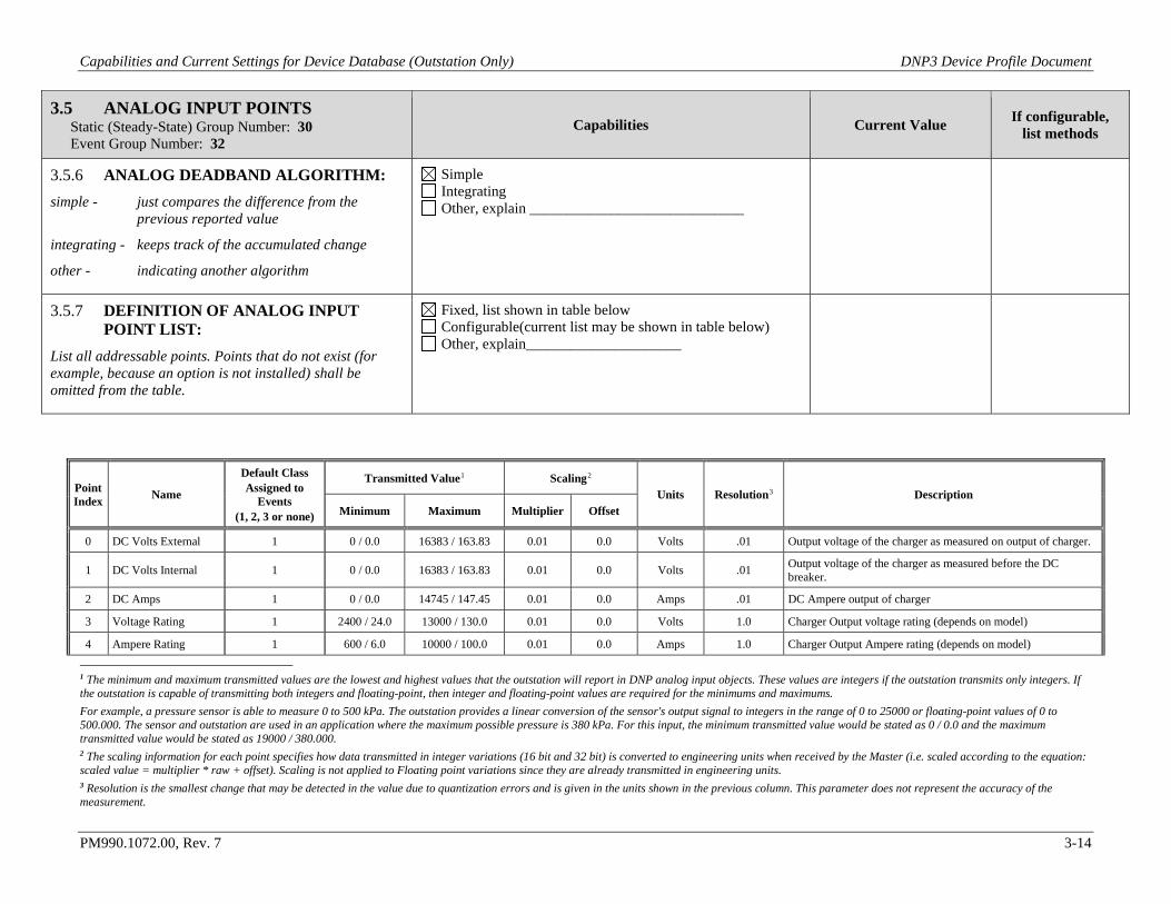
Capabilities and Current Settings for Device Database (Outstation Only) DNP3 Device Profile Document
PM990.1072.00, Rev. 7 3-14
3.5 ANALOG INPUT POINTS Static (Steady-State) Group Number: 30 Event Group Number: 32
Capabilities Current Value If configurable, list methods
3.5.6 ANALOG DEADBAND ALGORITHM: simple - just compares the difference from the
previous reported value
integrating - keeps track of the accumulated change
other - indicating another algorithm
Simple Integrating Other, explain _____________________________
3.5.7 DEFINITION OF ANALOG INPUT POINT LIST:
List all addressable points. Points that do not exist (for example, because an option is not installed) shall be omitted from the table.
Fixed, list shown in table below Configurable(current list may be shown in table below) Other, explain_____________________
Point Index Name
Default Class Assigned to
Events (1, 2, 3 or none)
Transmitted Value1 Scaling2 Units Resolution3 Description
Minimum Maximum Multiplier Offset
0 DC Volts External 1 0 / 0.0 16383 / 163.83 0.01 0.0 Volts .01 Output voltage of the charger as measured on output of charger.
1 DC Volts Internal 1 0 / 0.0 16383 / 163.83 0.01 0.0 Volts .01 Output voltage of the charger as measured before the DC breaker.
2 DC Amps 1 0 / 0.0 14745 / 147.45 0.01 0.0 Amps .01 DC Ampere output of charger
3 Voltage Rating 1 2400 / 24.0 13000 / 130.0 0.01 0.0 Volts 1.0 Charger Output voltage rating (depends on model)
4 Ampere Rating 1 600 / 6.0 10000 / 100.0 0.01 0.0 Amps 1.0 Charger Output Ampere rating (depends on model)
1 The minimum and maximum transmitted values are the lowest and highest values that the outstation will report in DNP analog input objects. These values are integers if the outstation transmits only integers. If the outstation is capable of transmitting both integers and floating-point, then integer and floating-point values are required for the minimums and maximums. For example, a pressure sensor is able to measure 0 to 500 kPa. The outstation provides a linear conversion of the sensor's output signal to integers in the range of 0 to 25000 or floating-point values of 0 to 500.000. The sensor and outstation are used in an application where the maximum possible pressure is 380 kPa. For this input, the minimum transmitted value would be stated as 0 / 0.0 and the maximum transmitted value would be stated as 19000 / 380.000. 2 The scaling information for each point specifies how data transmitted in integer variations (16 bit and 32 bit) is converted to engineering units when received by the Master (i.e. scaled according to the equation: scaled value = multiplier * raw + offset). Scaling is not applied to Floating point variations since they are already transmitted in engineering units. 3 Resolution is the smallest change that may be detected in the value due to quantization errors and is given in the units shown in the previous column. This parameter does not represent the accuracy of the measurement.
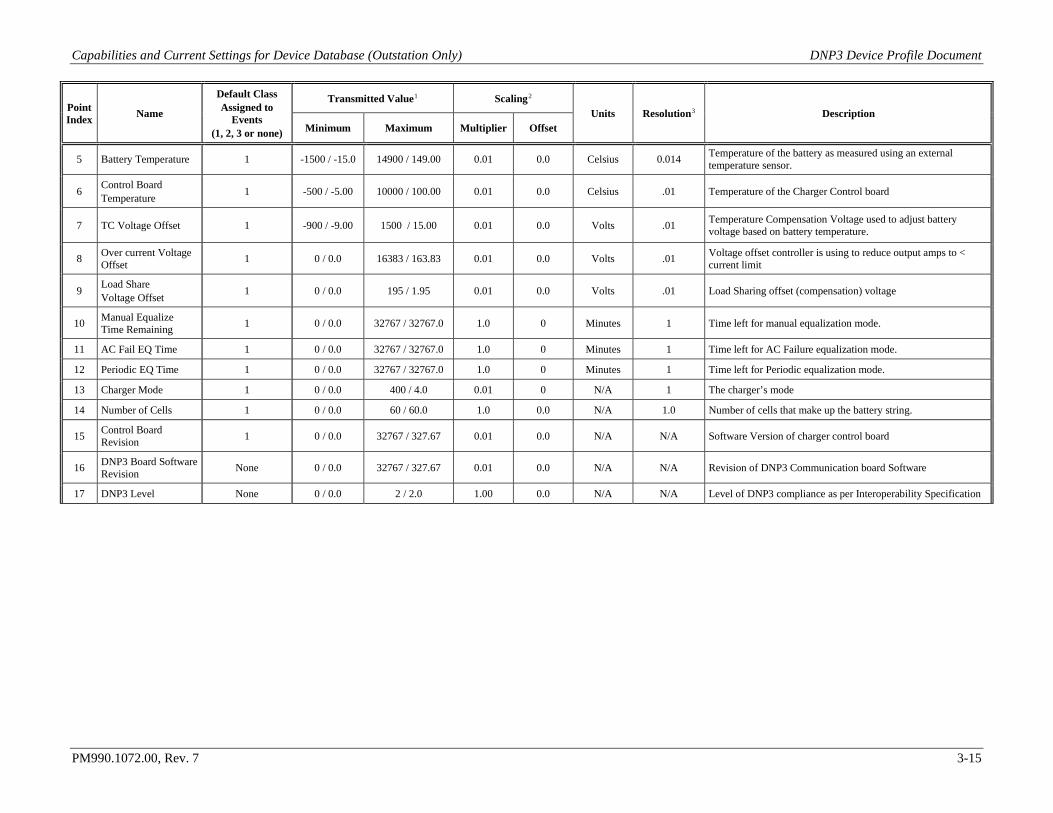
Capabilities and Current Settings for Device Database (Outstation Only) DNP3 Device Profile Document
PM990.1072.00, Rev. 7 3-15
Point Index Name
Default Class Assigned to
Events (1, 2, 3 or none)
Transmitted Value1 Scaling2 Units Resolution3 Description
Minimum Maximum Multiplier Offset
5 Battery Temperature 1 -1500 / -15.0 14900 / 149.00 0.01 0.0 Celsius 0.014 Temperature of the battery as measured using an external temperature sensor.
6 Control Board Temperature 1 -500 / -5.00 10000 / 100.00 0.01 0.0 Celsius .01 Temperature of the Charger Control board
7 TC Voltage Offset 1 -900 / -9.00 1500 / 15.00 0.01 0.0 Volts .01 Temperature Compensation Voltage used to adjust battery voltage based on battery temperature.
8 Over current Voltage Offset 1 0 / 0.0 16383 / 163.83 0.01 0.0 Volts .01 Voltage offset controller is using to reduce output amps to <
current limit
9 Load Share Voltage Offset 1 0 / 0.0 195 / 1.95 0.01 0.0 Volts .01 Load Sharing offset (compensation) voltage
10 Manual Equalize Time Remaining 1 0 / 0.0 32767 / 32767.0 1.0 0 Minutes 1 Time left for manual equalization mode.
11 AC Fail EQ Time 1 0 / 0.0 32767 / 32767.0 1.0 0 Minutes 1 Time left for AC Failure equalization mode.
12 Periodic EQ Time 1 0 / 0.0 32767 / 32767.0 1.0 0 Minutes 1 Time left for Periodic equalization mode.
13 Charger Mode 1 0 / 0.0 400 / 4.0 0.01 0 N/A 1 The charger’s mode
14 Number of Cells 1 0 / 0.0 60 / 60.0 1.0 0.0 N/A 1.0 Number of cells that make up the battery string.
15 Control Board Revision 1 0 / 0.0 32767 / 327.67 0.01 0.0 N/A N/A Software Version of charger control board
16 DNP3 Board Software Revision None 0 / 0.0 32767 / 327.67 0.01 0.0 N/A N/A Revision of DNP3 Communication board Software
17 DNP3 Level None 0 / 0.0 2 / 2.0 1.00 0.0 N/A N/A Level of DNP3 compliance as per Interoperability Specification
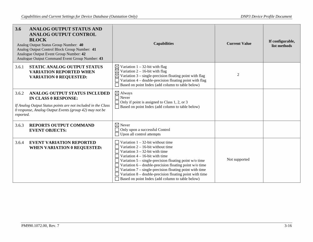
Capabilities and Current Settings for Device Database (Outstation Only) DNP3 Device Profile Document
PM990.1072.00, Rev. 7 3-16
3.6 ANALOG OUTPUT STATUS AND ANALOG OUTPUT CONTROL BLOCK
Analog Output Status Group Number: 40 Analog Output Control Block Group Number: 41 Analogue Output Event Group Number: 42 Analogue Output Command Event Group Number: 43
Capabilities Current Value If configurable, list methods
3.6.1 STATIC ANALOG OUTPUT STATUS VARIATION REPORTED WHEN VARIATION 0 REQUESTED:
Variation 1 – 32-bit with flag Variation 2 – 16-bit with flag Variation 3 – single-precision floating point with flag Variation 4 – double-precision floating point with flag Based on point Index (add column to table below)
2
3.6.2 ANALOG OUTPUT STATUS INCLUDED IN CLASS 0 RESPONSE:
If Analog Output Status points are not included in the Class 0 response, Analog Output Events (group 42) may not be reported.
Always Never Only if point is assigned to Class 1, 2, or 3 Based on point Index (add column to table below)
3.6.3 REPORTS OUTPUT COMMAND EVENT OBJECTS:
Never Only upon a successful Control Upon all control attempts
3.6.4 EVENT VARIATION REPORTED WHEN VARIATION 0 REQUESTED:
Variation 1 – 32-bit without time Variation 2 – 16-bit without time Variation 3 – 32-bit with time Variation 4 – 16-bit with time Variation 5 – single-precision floating point w/o time Variation 6 – double-precision floating point w/o time Variation 7 – single-precision floating point with time Variation 8 – double-precision floating point with time Based on point Index (add column to table below)
Not supported
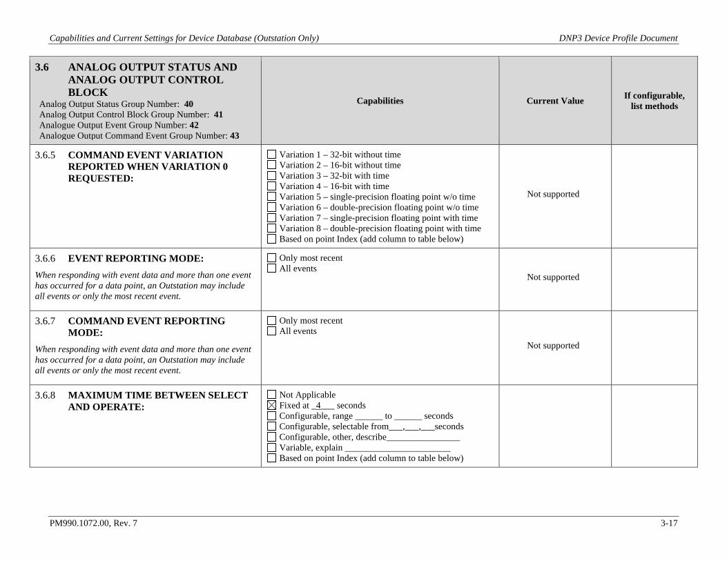
Capabilities and Current Settings for Device Database (Outstation Only) DNP3 Device Profile Document
PM990.1072.00, Rev. 7 3-17
3.6 ANALOG OUTPUT STATUS AND ANALOG OUTPUT CONTROL BLOCK
Analog Output Status Group Number: 40 Analog Output Control Block Group Number: 41 Analogue Output Event Group Number: 42 Analogue Output Command Event Group Number: 43
Capabilities Current Value If configurable, list methods
3.6.5 COMMAND EVENT VARIATION REPORTED WHEN VARIATION 0 REQUESTED:
Variation 1 – 32-bit without time Variation 2 – 16-bit without time Variation 3 – 32-bit with time Variation 4 – 16-bit with time Variation 5 – single-precision floating point w/o time Variation 6 – double-precision floating point w/o time Variation 7 – single-precision floating point with time Variation 8 – double-precision floating point with time Based on point Index (add column to table below)
Not supported
3.6.6 EVENT REPORTING MODE: When responding with event data and more than one event has occurred for a data point, an Outstation may include all events or only the most recent event.
Only most recent All events
Not supported
3.6.7 COMMAND EVENT REPORTING MODE:
When responding with event data and more than one event has occurred for a data point, an Outstation may include all events or only the most recent event.
Only most recent All events
Not supported
3.6.8 MAXIMUM TIME BETWEEN SELECT AND OPERATE:
Not Applicable Fixed at _4___ seconds Configurable, range ______ to ______ seconds Configurable, selectable from___,___,___seconds Configurable, other, describe________________ Variable, explain _______________________ Based on point Index (add column to table below)
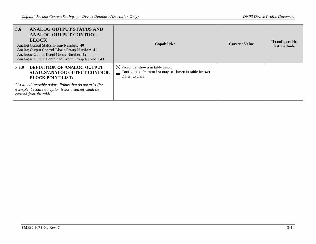
Capabilities and Current Settings for Device Database (Outstation Only) DNP3 Device Profile Document
PM990.1072.00, Rev. 7 3-18
3.6 ANALOG OUTPUT STATUS AND ANALOG OUTPUT CONTROL BLOCK
Analog Output Status Group Number: 40 Analog Output Control Block Group Number: 41 Analogue Output Event Group Number: 42 Analogue Output Command Event Group Number: 43
Capabilities Current Value If configurable, list methods
3.6.9 DEFINITION OF ANALOG OUTPUT STATUS/ANALOG OUTPUT CONTROL BLOCK POINT LIST:
List all addressable points. Points that do not exist (for example, because an option is not installed) shall be omitted from the table.
Fixed, list shown in table below Configurable(current list may be shown in table below) Other, explain_____________________
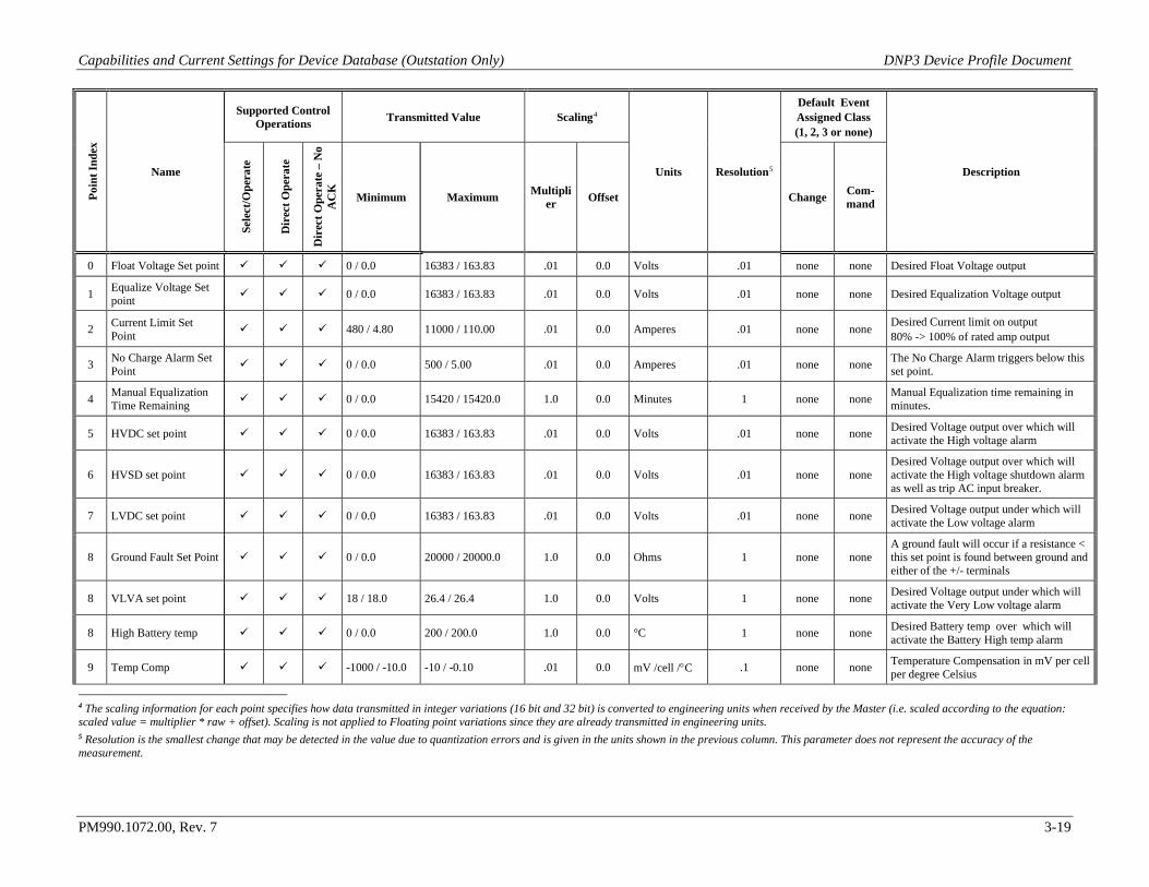
Capabilities and Current Settings for Device Database (Outstation Only) DNP3 Device Profile Document
PM990.1072.00, Rev. 7 3-19
Poin
t Ind
ex
Name
Supported Control Operations Transmitted Value Scaling4
Units Resolution5
Default Event Assigned Class (1, 2, 3 or none)
Description
Sele
ct/O
pera
te
Dir
ect O
pera
te
Dir
ect O
pera
te –
No
AC
K
Minimum Maximum Multiplier Offset Change Com-
mand
0 Float Voltage Set point 0 / 0.0 16383 / 163.83 .01 0.0 Volts .01 none none Desired Float Voltage output
1 Equalize Voltage Set point 0 / 0.0 16383 / 163.83 .01 0.0 Volts .01 none none Desired Equalization Voltage output
2 Current Limit Set Point 480 / 4.80 11000 / 110.00 .01 0.0 Amperes .01 none none Desired Current limit on output
80% -> 100% of rated amp output
3 No Charge Alarm Set Point 0 / 0.0 500 / 5.00 .01 0.0 Amperes .01 none none The No Charge Alarm triggers below this
set point.
4 Manual Equalization Time Remaining 0 / 0.0 15420 / 15420.0 1.0 0.0 Minutes 1 none none Manual Equalization time remaining in
minutes.
5 HVDC set point 0 / 0.0 16383 / 163.83 .01 0.0 Volts .01 none none Desired Voltage output over which will activate the High voltage alarm
6 HVSD set point 0 / 0.0 16383 / 163.83 .01 0.0 Volts .01 none none Desired Voltage output over which will activate the High voltage shutdown alarm as well as trip AC input breaker.
7 LVDC set point 0 / 0.0 16383 / 163.83 .01 0.0 Volts .01 none none Desired Voltage output under which will activate the Low voltage alarm
8 Ground Fault Set Point 0 / 0.0 20000 / 20000.0 1.0 0.0 Ohms 1 none none A ground fault will occur if a resistance < this set point is found between ground and either of the +/- terminals
8 VLVA set point 18 / 18.0 26.4 / 26.4 1.0 0.0 Volts 1 none none Desired Voltage output under which will activate the Very Low voltage alarm
8 High Battery temp 0 / 0.0 200 / 200.0 1.0 0.0 °C 1 none none Desired Battery temp over which will activate the Battery High temp alarm
9 Temp Comp -1000 / -10.0 -10 / -0.10 .01 0.0 mV /cell /°C .1 none none Temperature Compensation in mV per cell per degree Celsius
4 The scaling information for each point specifies how data transmitted in integer variations (16 bit and 32 bit) is converted to engineering units when received by the Master (i.e. scaled according to the equation: scaled value = multiplier * raw + offset). Scaling is not applied to Floating point variations since they are already transmitted in engineering units. 5 Resolution is the smallest change that may be detected in the value due to quantization errors and is given in the units shown in the previous column. This parameter does not represent the accuracy of the measurement.
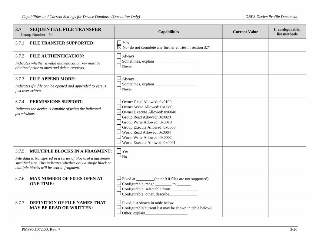
Capabilities and Current Settings for Device Database (Outstation Only) DNP3 Device Profile Document
PM990.1072.00, Rev. 7 3-20
3.7 SEQUENTIAL FILE TRANSFER Group Number: 70
Capabilities Current Value If configurable, list methods
3.7.1 FILE TRANSFER SUPPORTED: Yes No (do not complete any further entries in section 3.7)
3.7.2 FILE AUTHENTICATION: Indicates whether a valid authentication key must be obtained prior to open and delete requests.
Always Sometimes, explain _____________________ Never
3.7.3 FILE APPEND MODE: Indicates if a file can be opened and appended to versus just overwritten.
Always Sometimes, explain _____________________ Never
3.7.4 PERMISSIONS SUPPORT: Indicates the device is capable of using the indicated permissions.
Owner Read Allowed: 0x0100 Owner Write Allowed: 0x0080 Owner Execute Allowed: 0x0040 Group Read Allowed: 0x0020 Group Write Allowed: 0x0010 Group Execute Allowed: 0x0008 World Read Allowed: 0x0004 World Write Allowed: 0x0002 World Execute Allowed: 0x0001
3.7.5 MULTIPLE BLOCKS IN A FRAGMENT: File data is transferred in a series of blocks of a maximum specified size. This indicates whether only a single block or multiple blocks will be sent in fragment.
Yes No
3.7.6 MAX NUMBER OF FILES OPEN AT ONE TIME:
Fixed at _________(enter 0 if files are not supported) Configurable, range ________ to _______ Configurable, selectable from ____,____,____ Configurable, other, describe______________
3.7.7 DEFINITION OF FILE NAMES THAT MAY BE READ OR WRITTEN:
Fixed, list shown in table below Configurable(current list may be shown in table below) Other, explain_____________________
Capabilities and Current Settings for Device Database (Outstation Only) DNP3 Device Profile Document
PM990.1072.00, Rev. 7 3-21
File Name
Default Class Assigned to
Events (1, 2, 3 or none)
Authentication Required for:
Description Read Write Delete
Add more rows as necessary
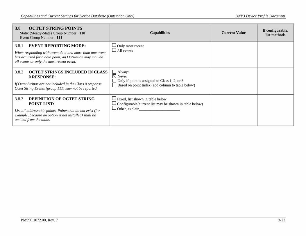
Capabilities and Current Settings for Device Database (Outstation Only) DNP3 Device Profile Document
PM990.1072.00, Rev. 7 3-22
3.8 OCTET STRING POINTS Static (Steady-State) Group Number: 110 Event Group Number: 111
Capabilities Current Value If configurable, list methods
3.8.1 EVENT REPORTING MODE: When responding with event data and more than one event has occurred for a data point, an Outstation may include all events or only the most recent event.
Only most recent All events
3.8.2 OCTET STRINGS INCLUDED IN CLASS 0 RESPONSE:
If Octet Strings are not included in the Class 0 response, Octet String Events (group 111) may not be reported.
Always Never Only if point is assigned to Class 1, 2, or 3 Based on point Index (add column to table below)
3.8.3 DEFINITION OF OCTET STRING POINT LIST:
List all addressable points. Points that do not exist (for example, because an option is not installed) shall be omitted from the table.
Fixed, list shown in table below Configurable(current list may be shown in table below) Other, explain_____________________
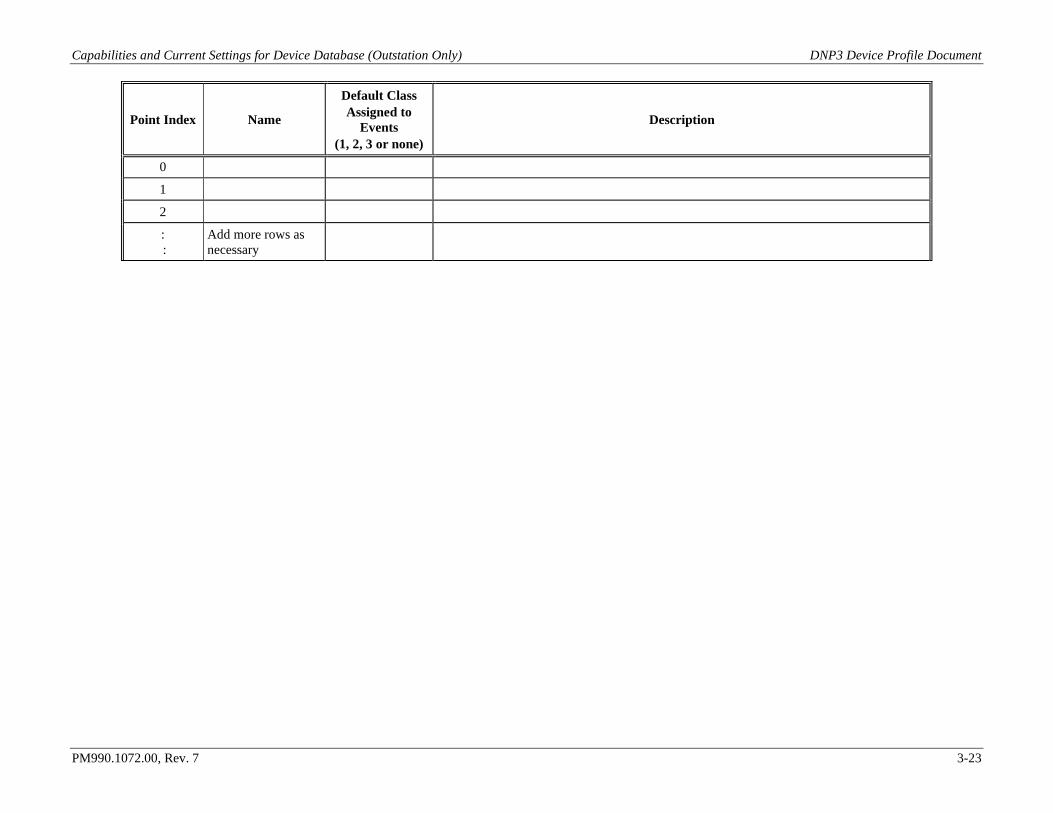
Capabilities and Current Settings for Device Database (Outstation Only) DNP3 Device Profile Document
PM990.1072.00, Rev. 7 3-23
Point Index Name
Default Class Assigned to
Events (1, 2, 3 or none)
Description
0
1
2
: :
Add more rows as necessary
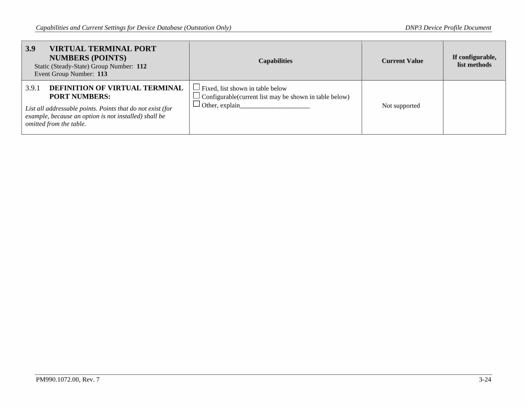
Capabilities and Current Settings for Device Database (Outstation Only) DNP3 Device Profile Document
PM990.1072.00, Rev. 7 3-24
3.9 VIRTUAL TERMINAL PORT NUMBERS (POINTS)
Static (Steady-State) Group Number: 112 Event Group Number: 113
Capabilities Current Value If configurable, list methods
3.9.1 DEFINITION OF VIRTUAL TERMINAL PORT NUMBERS:
List all addressable points. Points that do not exist (for example, because an option is not installed) shall be omitted from the table.
Fixed, list shown in table below Configurable(current list may be shown in table below) Other, explain_____________________ Not supported
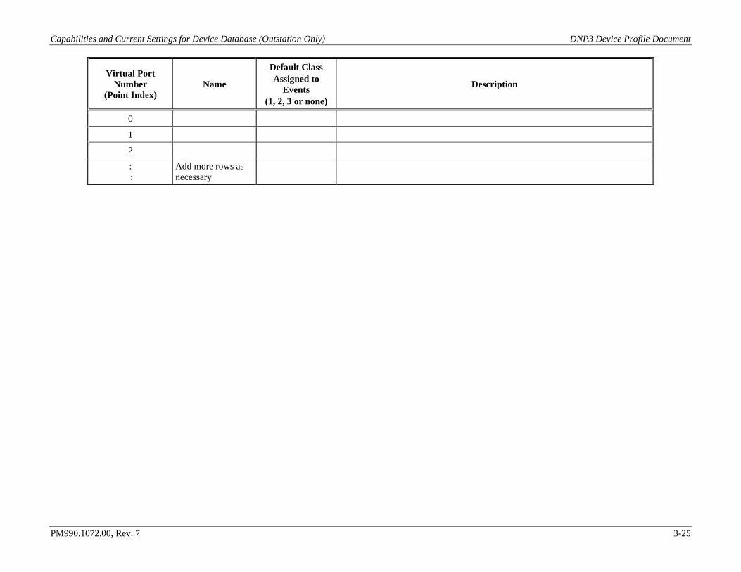
Capabilities and Current Settings for Device Database (Outstation Only) DNP3 Device Profile Document
PM990.1072.00, Rev. 7 3-25
Virtual Port Number
(Point Index) Name
Default Class Assigned to
Events (1, 2, 3 or none)
Description
0
1
2
: :
Add more rows as necessary
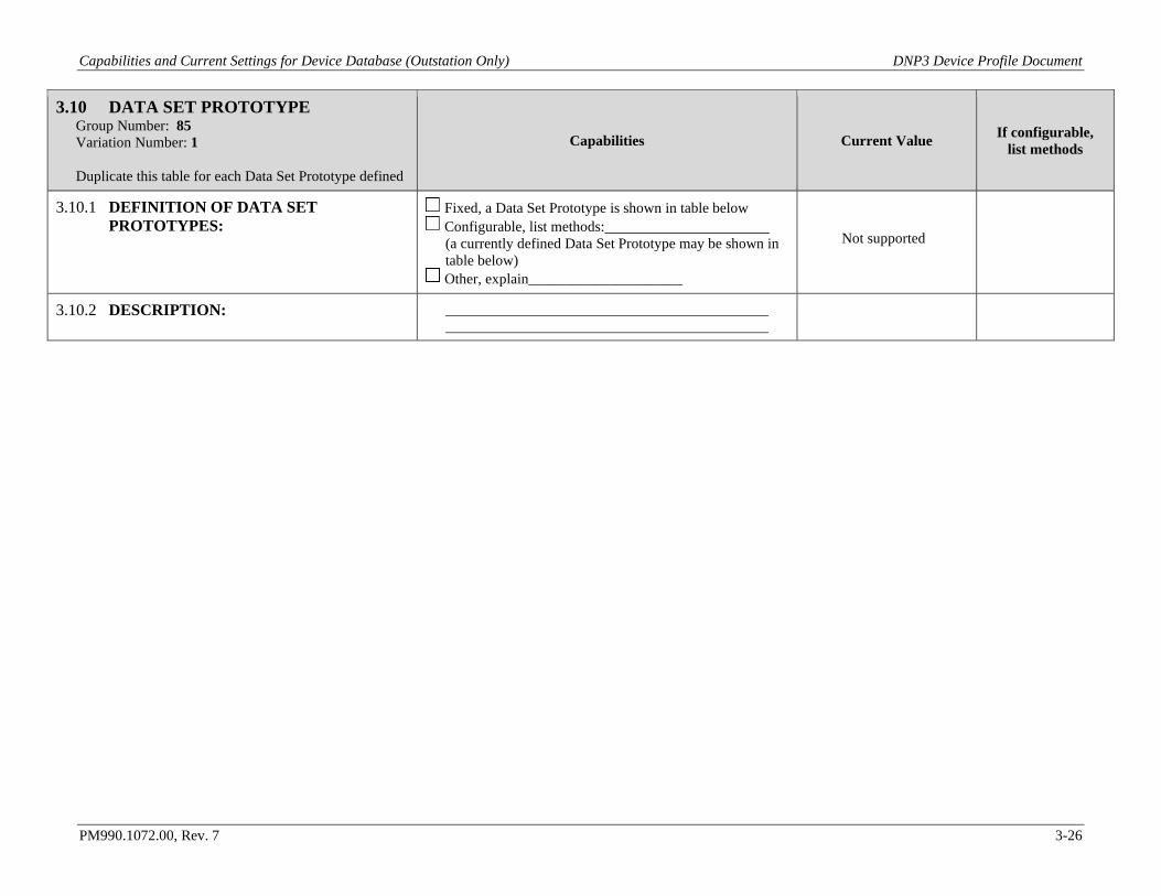
Capabilities and Current Settings for Device Database (Outstation Only) DNP3 Device Profile Document
PM990.1072.00, Rev. 7 3-26
3.10 DATA SET PROTOTYPE Group Number: 85 Variation Number: 1 Duplicate this table for each Data Set Prototype defined
Capabilities Current Value If configurable, list methods
3.10.1 DEFINITION OF DATA SET PROTOTYPES:
Fixed, a Data Set Prototype is shown in table below Configurable, list methods: (a currently defined Data Set Prototype may be shown in table below)
Other, explain_____________________
Not supported
3.10.2 DESCRIPTION:

Capabilities and Current Settings for Device Database (Outstation Only) DNP3 Device Profile Document
PM990.1072.00, Rev. 7 3-27
Ele
men
t Num
ber
Descriptor Code (check one)
Element Description
Data Type Code (check one)
Max
imum
Dat
a L
engt
h Ancillary Value: ID = Identifier number UUID = UUID value NSPC = Prototype namespace NAME= Prototype name DAEL = Data element name CTLS = Control status name CTLV = Control value name
ID
UU
ID
NSP
C
NA
ME
DA
EL
CT
LS
CT
LV
NO
NE
VST
R
UIN
T
INT
FLT
OST
R
BST
R
TIM
E
UN
CD
0 X Mandatory DNP identifier X
1 X UUID assigned to prototype X
2
: : Add more rows as necessary
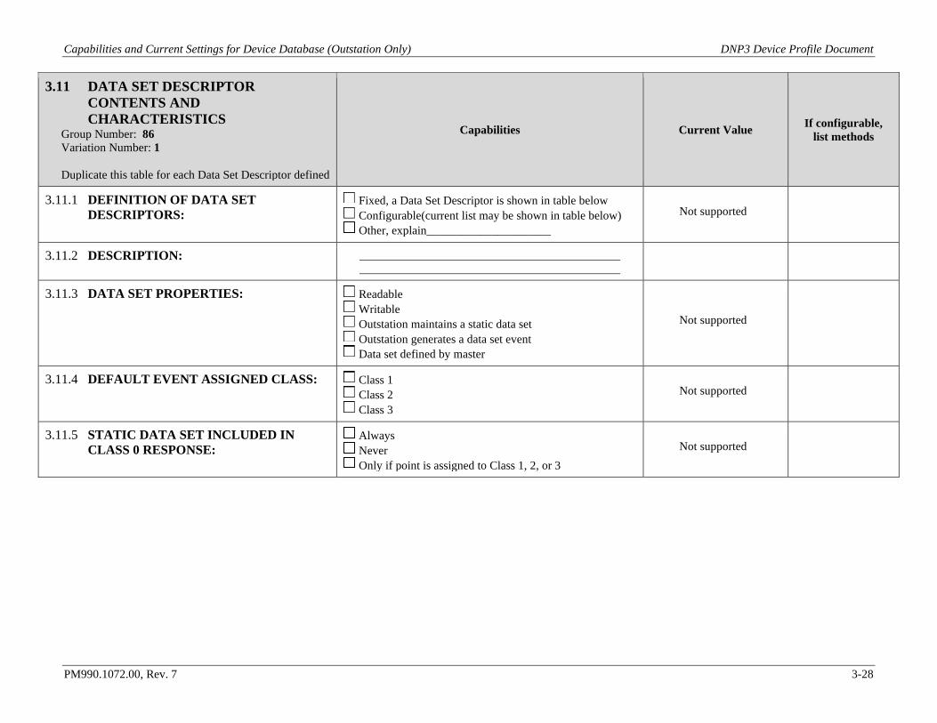
Capabilities and Current Settings for Device Database (Outstation Only) DNP3 Device Profile Document
PM990.1072.00, Rev. 7 3-28
3.11 DATA SET DESCRIPTOR CONTENTS AND CHARACTERISTICS
Group Number: 86 Variation Number: 1 Duplicate this table for each Data Set Descriptor defined
Capabilities Current Value If configurable, list methods
3.11.1 DEFINITION OF DATA SET DESCRIPTORS:
Fixed, a Data Set Descriptor is shown in table below Configurable(current list may be shown in table below) Other, explain_____________________
Not supported
3.11.2 DESCRIPTION:
3.11.3 DATA SET PROPERTIES: Readable Writable Outstation maintains a static data set Outstation generates a data set event Data set defined by master
Not supported
3.11.4 DEFAULT EVENT ASSIGNED CLASS: Class 1 Class 2 Class 3
Not supported
3.11.5 STATIC DATA SET INCLUDED IN CLASS 0 RESPONSE:
Always Never Only if point is assigned to Class 1, 2, or 3
Not supported
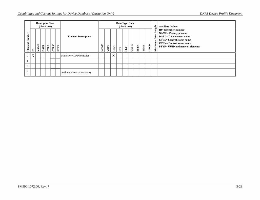
Capabilities and Current Settings for Device Database (Outstation Only) DNP3 Device Profile Document
PM990.1072.00, Rev. 7 3-29
Ele
men
t Num
ber
Descriptor Code (check one)
Element Description
Data Type Code (check one)
Max
imum
Dat
a L
engt
h Ancillary Value: ID = Identifier number NAME= Prototype name DAEL = Data element name CTLS = Control status name CTLV = Control value name PTYP = UUID and name of elements
ID
NA
ME
DA
EL
CT
LS
CT
LV
PTY
P
NO
NE
VST
R
UIN
T
INT
FLT
OST
R
BST
R
TIM
E
UN
CD
0 X Mandatory DNP identifier X
1
2
: : Add more rows as necessary
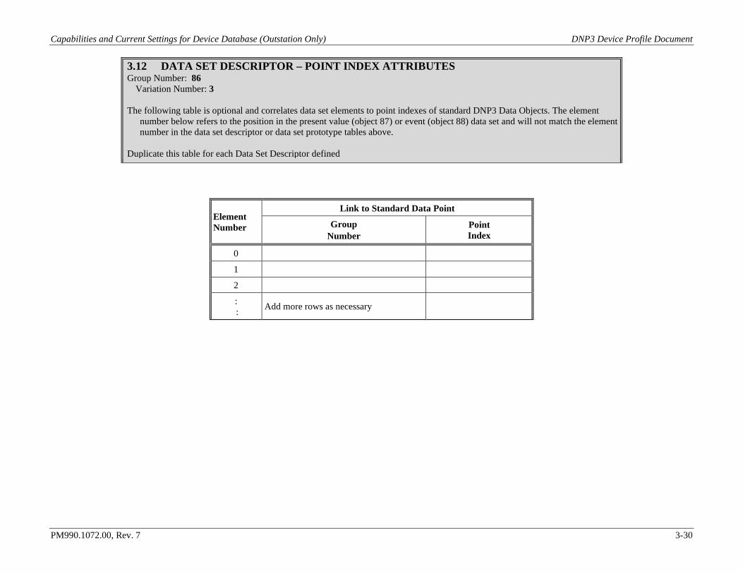
Capabilities and Current Settings for Device Database (Outstation Only) DNP3 Device Profile Document
PM990.1072.00, Rev. 7 3-30
3.12 DATA SET DESCRIPTOR – POINT INDEX ATTRIBUTES Group Number: 86
Variation Number: 3
The following table is optional and correlates data set elements to point indexes of standard DNP3 Data Objects. The element number below refers to the position in the present value (object 87) or event (object 88) data set and will not match the element number in the data set descriptor or data set prototype tables above.
Duplicate this table for each Data Set Descriptor defined
Element Number
Link to Standard Data Point
Group Number
Point Index
0
1
2
: : Add more rows as necessary
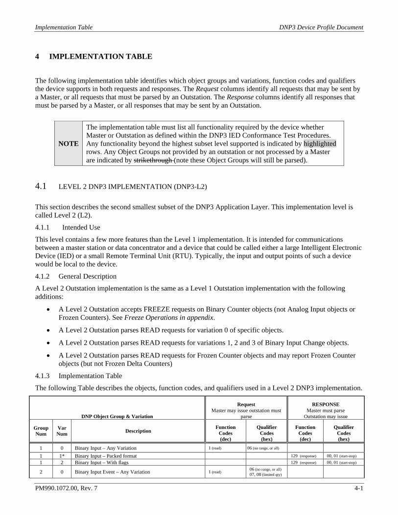
Implementation Table DNP3 Device Profile Document
PM990.1072.00, Rev. 7 4-1
4 IMPLEMENTATION TABLE
The following implementation table identifies which object groups and variations, function codes and qualifiers the device supports in both requests and responses. The Request columns identify all requests that may be sent by a Master, or all requests that must be parsed by an Outstation. The Response columns identify all responses that must be parsed by a Master, or all responses that may be sent by an Outstation. 4.1 LEVEL 2 DNP3 IMPLEMENTATION (DNP3-L2)
This section describes the second smallest subset of the DNP3 Application Layer. This implementation level is called Level 2 (L2).
4.1.1 Intended Use
This level contains a few more features than the Level 1 implementation. It is intended for communications between a master station or data concentrator and a device that could be called either a large Intelligent Electronic Device (IED) or a small Remote Terminal Unit (RTU). Typically, the input and output points of such a device would be local to the device.
4.1.2 General Description
A Level 2 Outstation implementation is the same as a Level 1 Outstation implementation with the following additions:
• A Level 2 Outstation accepts FREEZE requests on Binary Counter objects (not Analog Input objects or Frozen Counters). See Freeze Operations in appendix.
• A Level 2 Outstation parses READ requests for variation 0 of specific objects.
• A Level 2 Outstation parses READ requests for variations 1, 2 and 3 of Binary Input Change objects.
• A Level 2 Outstation parses READ requests for Frozen Counter objects and may report Frozen Counter objects (but not Frozen Delta Counters)
4.1.3 Implementation Table
The following Table describes the objects, function codes, and qualifiers used in a Level 2 DNP3 implementation.
DNP Object Group & Variation
Request Master may issue outstation must
parse
RESPONSE Master must parse
Outstation may issue
Group Num
Var Num Description
Function Codes (dec)
Qualifier Codes (hex)
Function Codes (dec)
Qualifier Codes (hex)
1 0 Binary Input – Any Variation 1 (read) 06 (no range, or all)
1 1* Binary Input – Packed format 129 (response) 00, 01 (start-stop) 1 2 Binary Input – With flags 129 (response) 00, 01 (start-stop)
2 0 Binary Input Event – Any Variation 1 (read) 06 (no range, or all) 07, 08 (limited qty)
NOTE
The implementation table must list all functionality required by the device whether Master or Outstation as defined within the DNP3 IED Conformance Test Procedures. Any functionality beyond the highest subset level supported is indicated by highlighted rows. Any Object Groups not provided by an outstation or not processed by a Master are indicated by strikethrough (note these Object Groups will still be parsed).
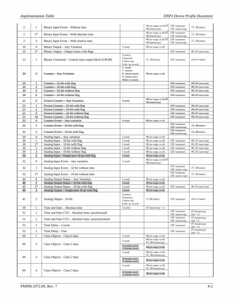
Implementation Table DNP3 Device Profile Document
PM990.1072.00, Rev. 7 4-2
2 1 Binary Input Event – Without time 06 (no range, or all) 07 08 (limited qty)
129 (response) 130 (unsol.resp) 17, 28 (index)
2 2* Binary Input Event – With absolute time 06 (no range, or all) 07 08 (limited qty)
129 (response) 130 (unsol.resp) 17, 28 (index)
2 3 Binary Input Event – With relative time 06 (no range, or all) 07 08 (limited qty)
129 (response) 130 (unsol.resp) 17, 28 (index)
10 0 Binary Output – Any Variation 1 (read) 06 (no range, or all)
10 2* Binary Output – Output status with flags 129 (response) 00, 01 (start-stop)
12 1 Binary Command – Control relay output block (CROB) 3 (select) 4 (operate) 5 (direct op) 6 (dir. op, no ack)
17, 28 (index) 129 (response) echo of request
20 0 Counter – Any Variation
1 (read) 7 (freeze) 8 (freeze noack) 9 (freeze clear) 10(frz. cl. noack)
06 (no range, or all)
20 1 Counter – 32-bit with flag 129 (response) 00, 01 (start-stop) 20 2 Counter – 16-bit with flag 129 (response) 00, 01 (start-stop) 20 5 Counter – 32-bit without flag 129 (response) 00, 01 (start-stop)
20 6 Counter – 16-bit without flag 129 (response) 00, 01 (start-stop)
21 0 Frozen Counter – Any Variation 1 (read) 06 (no range, or all) 07 08 (limited qty)
21 1 Frozen Counter – 32-bit with flag 129 (response) 00, 01 (start-stop) 21 2 Frozen Counter – 16-bit with flag 129 (response) 00, 01 (start-stop) 21 9 Frozen Counter – 32-bit without flag 129 (response) 00, 01 (start-stop) 21 10 Frozen Counter – 16-bit without flag 129 (response) 00, 01 (start-stop) 22 0 Counter Event – Any variation 1 (read) 06 (no range, or all)
22 1 Counter Event – 32-bit with flag 129 (response) 130 (unsol.resp) 17, 28 (index)
22 2 Counter Event – 16-bit with flag 129 (response) 130 (unsol.resp) 17, 28 (index)
30 0 Analog Input – Any variation 1 (read) 06 (no range, or all) 30 1 Analog Input – 32-bit with flag 1 (read) 06 (no range, or all) 129 (response) 00, 01 (start-stop) 30 2* Analog Input – 16-bit with flag 1 (read) 06 (no range, or all) 129 (response) 00, 01 (start-stop) 30 3 Analog Input – 32-bit without flag 1 (read) 06 (no range, or all) 129 (response) 00, 01 (start-stop) 30 4 Analog Input – 16-bit without flag 1 (read) 06 (no range, or all) 129 (response) 00, 01 (start-stop) 30 5 Analog Input – Single-prec flt-pt with flag 1 (read) 06 (no range, or all)
32 0 Analog Input Event – Any variation 1 (read) 06 (no range, or all) 07 08 (limited qty)
32 1 Analog Input Event – 32-bit without time 129 (response) 130 (unsol. resp) 17, 28 (index)
32 2* Analog Input Event – 16-bit without time 129 (response) 130 (unsol. resp) 17, 28 (index)
40 0 Analog Output Status – Any Variation 1 (read) 06 (no range, or all) 40 1 Analog Output Status – 32 bit with flag 1 (read) 06 (no range, or all) 40 2* Analog Output Status – 16-bit with flag 1 (read) 06 (no range, or all) 129 (response) 00, 01 (start-stop) 40 3 Analog Output – Single-prec flt-pt with flag 1 (read) 06 (no range, or all)
41 2 Analog Output – 16-bit 3 (select) 4 (operate) 5 (direct op) 6 (dir. op, no ack)
17,28 (index) 129 (response) echo of request
50 1 Time and Date – Absolute time 2 (write) 07 (limited qty = 1)
51 1 Time and Date CTO – Absolute time, synchronized 129 (response) 130 (unsol.resp)
07 (limited qty) (qty = 1)
51 2 Time and Date CTO – Absolute time, unsynchronized 129 (response) 130 (unsol.resp)
07 (limited qty) (qty = 1)
52 1 Time Delay – Coarse 129 (response) 07 (limited qty) (qty = 1)
52 2 Time Delay – Fine 129 (response) 07 (limited qty) (qty = 1)
60 1 Class Objects – Class 0 data 1 (read) 06 (no range, or all)
60 2 Class Objects – Class 1 data 1 (read) 06 (no range, or all)
07, 08 (limited qty) 20 (enable unsol.) 21 (disable unsol.) 06 (no range, or all)
60 3 Class Objects – Class 2 data 1 (read)
06 (no range, or all) 07, 08 (limited qty)
20 (enable unsol.) 21 (disable unsol.) 06 (no range, or all)
60 4 Class Objects – Class 3 data
1 (read)
06 (no range, or all) 07, 08 (limited qty)
20 (enable unsol.) 21 (disable unsol.) 06 (no range, or all)

Implementation Table DNP3 Device Profile Document
PM990.1072.00, Rev. 7 4-3
80 1 Internal Indications – Packed format 2 (write) 00 (start-stop) index=7
No Object (function code only) 13 (cold restart) No Object (function code only) 14 (warm restart) No Object (function code only) 23 (delay meas.) No Object (function code only) 24 (rec. cur. time)
Note: * - Default variation reported for variation 0.
Implementation Table DNP3 Device Profile Document
PM990.1072.00, Rev. 7 5-4
5 PRODUCT SUPPORT
Product support can be obtained using the following addresses and telephone numbers. Corporate office: UNIPOWER, LLC 210 N University Dr Coral Springs, FL 33071 United States
Manufacturing facility: UNIPOWER, LLC 65 Industrial Park Rd Dunlap, TN 37327 United States
Manufacturing facility: UNIPOWER Slovakia SRO ZLATOVSKA 1279 Business Center 22 91105 Trencin, Slovakia
Phone: +1-954-346-2442 Toll Free: 1-800-440-3504 Web site – www.unipowerco.com When contacting UNIPOWER, please be prepared to provide: 1. The product model number, spec number, S build number, and serial number - see the equipment nameplate
on the front panel 2. Your company’s name and address 3. Your name and title 4. The reason for the contact 5. If there is a problem with product operation:
• Is the problem intermittent or continuous? • What revision is the firmware? • What actions were being performed prior to the appearance of the problem? • What actions have been taken since the problem occurred?