dnp3 point list manual - library.e.abb.com · the dnp protocol implementation in the ied conforms...
TRANSCRIPT

Relion® Protection and Control
670 series 2.0 ANSIDNP3 Point List Manual

Document ID: 1MRK 511 307-UUSIssued: May 2014
Revision: -Product version: 2.0
© Copyright 2014 ABB. All rights reserved
CopyrightThis document and parts thereof must not be reproduced or copied without writtenpermission from ABB, and the contents thereof must not be imparted to a third party,nor used for any unauthorized purpose.
The software and hardware described in this document is furnished under a license andmay be used or disclosed only in accordance with the terms of such license.
This product includes software developed by the OpenSSL Project for use in theOpenSSL Toolkit. (http://www.openssl.org/)
This product includes cryptographic software written/developed by: Eric Young([email protected]) and Tim Hudson ([email protected]).
TrademarksABB and Relion are registered trademarks of the ABB Group. All other brand orproduct names mentioned in this document may be trademarks or registeredtrademarks of their respective holders.
WarrantyPlease inquire about the terms of warranty from your nearest ABB representative.

DisclaimerThe data, examples and diagrams in this manual are included solely for the concept orproduct description and are not to be deemed as a statement of guaranteed properties.All persons responsible for applying the equipment addressed in this manual mustsatisfy themselves that each intended application is suitable and acceptable, includingthat any applicable safety or other operational requirements are complied with. Inparticular, any risks in applications where a system failure and/or product failure wouldcreate a risk for harm to property or persons (including but not limited to personalinjuries or death) shall be the sole responsibility of the person or entity applying theequipment, and those so responsible are hereby requested to ensure that all measuresare taken to exclude or mitigate such risks.
This document has been carefully checked by ABB but deviations cannot becompletely ruled out. In case any errors are detected, the reader is kindly requested tonotify the manufacturer. Other than under explicit contractual commitments, in noevent shall ABB be responsible or liable for any loss or damage resulting from the useof this manual or the application of the equipment.

ConformityThis product complies with the directive of the Council of the European Communitieson the approximation of the laws of the Member States relating to electromagneticcompatibility (EMC Directive 2004/108/EC) and concerning electrical equipment foruse within specified voltage limits (Low-voltage directive 2006/95/EC). Thisconformity is the result of tests conducted by ABB in accordance with the productstandard EN 60255-26 for the EMC directive, and with the product standards EN60255-1 and EN 60255-27 for the low voltage directive. The product is designed inaccordance with the international standards of the IEC 60255 series and ANSI C37.90.The DNP protocol implementation in the IED conforms to "DNP3 IntelligentElectronic Device (IED) Certification Procedure Subset Level 2", available atwww.dnp.org .
Table of contents
Section 1 Introduction............................................................................3This manual..............................................................................................3Intended audience....................................................................................3Product documentation.............................................................................4
Product documentation set..................................................................4Document revision history...................................................................5Related documents..............................................................................6
Document symbols and conventions........................................................7Symbols...............................................................................................7Document conventions........................................................................8Functions included in 670 series IEDs................................................9
Section 2 DNP3 data mappings..........................................................19Overview.................................................................................................19Point list for the 670 series IEDs.............................................................19
Section 3 DNP3 protocol implementation............................................47DNP3 device profile................................................................................47DNP3 implementation table....................................................................63
Section 4 Glossary..............................................................................69Glossary..................................................................................................69
Table of contents
670 series 2.0 ANSI 1Point List Manual

2
Section 1 Introduction
1.1 This manual
The point list manual describes the outlook and properties of the data points specific tothe IED. The manual should be used in conjunction with the correspondingcommunication protocol manual.
1.2 Intended audience
This manual addresses the communication system engineer or system integratorresponsible for pre-engineering and engineering for communication setup in asubstation from an IED perspective.
The system engineer or system integrator must have a basic knowledge ofcommunication in protection and control systems and thorough knowledge of thespecific communication protocol.
1MRK 511 307-UUS - Section 1Introduction
670 series 2.0 ANSI 3Point List Manual
1.3 Product documentation
1.3.1 Product documentation set
IEC07000220-4-en.vsd
Pla
nnin
g &
pur
chas
e
Eng
inee
ring
Inst
allin
g
Com
mis
sion
ing
Ope
ratio
n
Mai
nten
ance
Dec
omm
issi
onin
gD
eins
talli
ng &
dis
posa
l
Application manual
Operation manual
Installation manual
Engineering manual
Communication protocol manual
Cyber security deployment guideline
Technical manual
Commissioning manual
IEC07000220 V4 EN
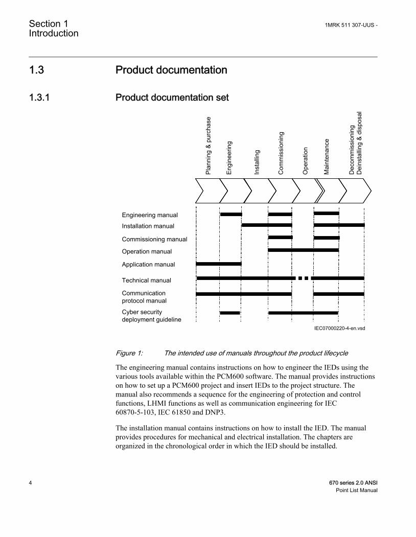
Figure 1: The intended use of manuals throughout the product lifecycle
The engineering manual contains instructions on how to engineer the IEDs using thevarious tools available within the PCM600 software. The manual provides instructionson how to set up a PCM600 project and insert IEDs to the project structure. Themanual also recommends a sequence for the engineering of protection and controlfunctions, LHMI functions as well as communication engineering for IEC60870-5-103, IEC 61850 and DNP3.
The installation manual contains instructions on how to install the IED. The manualprovides procedures for mechanical and electrical installation. The chapters areorganized in the chronological order in which the IED should be installed.
Section 1 1MRK 511 307-UUS -Introduction
4 670 series 2.0 ANSIPoint List Manual
The commissioning manual contains instructions on how to commission the IED. Themanual can also be used by system engineers and maintenance personnel for assistanceduring the testing phase. The manual provides procedures for the checking of externalcircuitry and energizing the IED, parameter setting and configuration as well asverifying settings by secondary injection. The manual describes the process of testingan IED in a substation which is not in service. The chapters are organized in thechronological order in which the IED should be commissioned. The relevantprocedures may be followed also during the service and maintenance activities.
The operation manual contains instructions on how to operate the IED once it has beencommissioned. The manual provides instructions for the monitoring, controlling andsetting of the IED. The manual also describes how to identify disturbances and how toview calculated and measured power grid data to determine the cause of a fault.
The application manual contains application descriptions and setting guidelines sortedper function. The manual can be used to find out when and for what purpose a typicalprotection function can be used. The manual can also provide assistance for calculatingsettings.
The technical manual contains application and functionality descriptions and listsfunction blocks, logic diagrams, input and output signals, setting parameters andtechnical data, sorted per function. The manual can be used as a technical referenceduring the engineering phase, installation and commissioning phase, and during normalservice.
The communication protocol manual describes the communication protocols supportedby the IED. The manual concentrates on the vendor-specific implementations.
The point list manual describes the outlook and properties of the data points specific tothe IED. The manual should be used in conjunction with the correspondingcommunication protocol manual.
The cyber security deployment guideline describes the process for handling cybersecurity when communicating with the IED. Certification, Authorization with rolebased access control, and product engineering for cyber security related events aredescribed and sorted by function. The guideline can be used as a technical referenceduring the engineering phase, installation and commissioning phase, and during normalservice.
1.3.2 Document revision historyDocument revision/date History-/May 2014 First release
1MRK 511 307-UUS - Section 1Introduction
670 series 2.0 ANSI 5Point List Manual
1.3.3 Related documentsDocuments related to REB670 Identify numberApplication manual 1MRK 505 302-UUS
Commissioning manual 1MRK 505 304-UUS
Product guide 1MRK 505 305-BUS
Technical manual 1MRK 505 303-UUS
Type test certificate 1MRK 505 305-TUS
Documents related to REC670 Identify numberApplication manual 1MRK 511 310-UUS
Commissioning manual 1MRK 511 312-UUS
Product guide 1MRK 511 313-BUS
Technical manual 1MRK 511 311-UUS
Type test certificate 1MRK 511 313-TUS
Documents related to RED670 Identify numberApplication manual 1MRK 505 307-UUS
Commissioning manual 1MRK 505 309-UUS
Product guide 1MRK 505 310-BUS
Technical manual 1MRK 505 308-UUS
Type test certificate 1MRK 505 310-TUS
Documents related to REG670 Identify numberApplication manual 1MRK 502 051-UUS
Commissioning manual 1MRK 502 053-UUS
Product guide 1MRK 502 054-BUS
Technical manual 1MRK 502 052-UUS
Type test certificate 1MRK 502 054-TUS
Documents related to REL670 Identify numberApplication manual 1MRK 506 338-UUS
Commissioning manual 1MRK 506 340-UUS
Product guide 1MRK 506 341-BUS
Technical manual 1MRK 506 339-UUS
Type test certificate 1MRK 506 341-TUS
Section 1 1MRK 511 307-UUS -Introduction
6 670 series 2.0 ANSIPoint List Manual
Documents related to RET670 Identify numberApplication manual 1MRK 504 138-UUS
Commissioning manual 1MRK 504 140-UUS
Product guide 1MRK 504 141-BUS
Technical manual 1MRK 504 139-UUS
Type test certificate 1MRK 504 141-TUS
670 series manuals Identify numberOperation manual 1MRK 500 118-UUS
Engineering manual 1MRK 511 308-UUS
Installation manual 1MRK 514 019-UUS
Communication protocol manual, DNP3 1MRK 511 301-UUS
Communication protocol manual, IEC 61850Edition 2
1MRK 511 303-UUS
Accessories guide 1MRK 514 012-BUS
Connection and Installation components 1MRK 513 003-BEN
Test system, COMBITEST 1MRK 512 001-BEN
1.4 Document symbols and conventions
1.4.1 Symbols
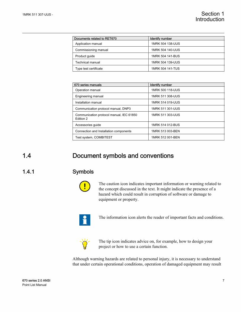
The caution icon indicates important information or warning related tothe concept discussed in the text. It might indicate the presence of ahazard which could result in corruption of software or damage toequipment or property.
The information icon alerts the reader of important facts and conditions.
The tip icon indicates advice on, for example, how to design yourproject or how to use a certain function.
Although warning hazards are related to personal injury, it is necessary to understandthat under certain operational conditions, operation of damaged equipment may result
1MRK 511 307-UUS - Section 1Introduction
670 series 2.0 ANSI 7Point List Manual
in degraded process performance leading to personal injury or death. It is importantthat the user fully complies with all warning and cautionary notices.
1.4.2 Document conventions• Abbreviations and acronyms in this manual are spelled out in the glossary. The
glossary also contains definitions of important terms.• Push button navigation in the LHMI menu structure is presented by using the push
button icons.For example, to navigate between the options, use and .
• HMI menu paths are presented in bold.For example, select Main menu/Settings.
• LHMI messages are shown in Courier font.For example, to save the changes in non-volatile memory, select Yes and press
.• Parameter names are shown in italics.
For example, the function can be enabled and disabled with the Operation setting.• Each function block symbol shows the available input/output signal.
• the character ^ in front of an input/output signal name indicates that thesignal name may be customized using the PCM600 software.
• the character * after an input/output signal name indicates that the signalmust be connected to another function block in the application configurationto achieve a valid application configuration.
• Logic diagrams describe the signal logic inside the function block and arebordered by dashed lines.• Signals in frames with a shaded area on their right hand side represent
setting parameter signals that are only settable via the PST or LHMI.• If an internal signal path cannot be drawn with a continuous line, the suffix -
int is added to the signal name to indicate where the signal starts and continues.• Signal paths that extend beyond the logic diagram and continue in another
diagram have the suffix ”-cont.”• Dimensions are provided both in inches and mm. If it is not specifically mentioned
then the dimension is in mm.
Section 1 1MRK 511 307-UUS -Introduction
8 670 series 2.0 ANSIPoint List Manual
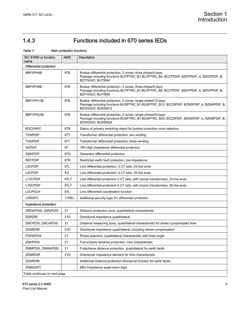
1.4.3 Functions included in 670 series IEDsTable 1: Main protection functions
IEC 61850 or functionname
ANSI Description
Differential protection
BBP3PH4B 87B Busbar differential protection, 2 zones, three phase/4 baysPackage including functions BUTPTRC_B1-BUTPTRC_B4, BCZTPDIF, BZNTPDIF_A, BZNTPDIF_B,BZITGGIO, BUTSM4
BBP3PH8B 87B Busbar differential protection, 2 zones, three phase/8 baysPackage including functions BUTPTRC_B1-BUTPTRC_B8, BCZTPDIF, BZNTPDIF_A, BZNTPDIF_B,BZITGGIO, BUTSM8
BBP1PH12B 87B Busbar differential protection, 2 zones, single phase/12 baysPackage including functions BUSPTRC_B1-BUSPTRC_B12, BCZSPDIF, BZNSPDIF_A, BZNSPDIF_B,BZISGGIO, BUSSM12
BBP1PH24B 87B Busbar differential protection, 2 zones, single phase/24 baysPackage including functions BUSPTRC_B1-BUSPTRC_B24, BCZSPDIF, BZNSPDIF_A, BZNSPDIF_B,BZISGGIO, BUSSM24
BDCGAPC 87B Status of primary switching object for busbar protection zone selection
T2WPDIF 87T Transformer differential protection, two winding
T3WPDIF 87T Transformer differential protection, three winding
HZPDIF 87 1Ph High impedance differential protection
GENPDIF 87G Generator differential protection
REFPDIF 87N Restricted earth fault protection, low impedance
L3CPDIF 87L Line differential protection, 3 CT sets, 23 line ends
L6CPDIF 87L Line differential protection, 6 CT sets, 35 line ends
LT3CPDIF 87LT Line differential protection 3 CT sets, with inzone transformers, 23 line ends
LT6CPDIF 87LT Line differential protection 6 CT sets, with inzone transformers, 35 line ends
LDLPSCH 87L Line differential coordination function
LDRGFC 11REL Additional security logic for differential protection
Impedance protection
ZMQAPDIS, ZMQPDIS 21 Distance protection zone, quadrilateral characteristic
ZDRDIR 21D Directional impedance quadrilateral
ZMCPDIS, ZMCAPDIS 21 Distance measuring zone, quadrilateral characteristic for series compensated lines
ZDSRDIR 21D Directional impedance quadrilateral, including series compensation
FDPSPDIS 21 Phase selection, quadrilateral characteristic with fixed angle
ZMHPDIS 21 Full-scheme distance protection, mho characteristic
ZMMPDIS, ZMMAPDIS 21 Fullscheme distance protection, quadrilateral for earth faults
ZDMRDIR 21D Directional impedance element for mho characteristic
ZDARDIR Additional distance protection directional function for earth faults
ZSMGAPC Mho Impedance supervision logic
Table continues on next page
1MRK 511 307-UUS - Section 1Introduction
670 series 2.0 ANSI 9Point List Manual
IEC 61850 or functionname
ANSI Description
FMPSPDIS 21 Faulty phase identification with load enchroachment
ZMRPDIS, ZMRAPDIS 21 Distance protection zone, quadrilateral characteristic, separate settings
FRPSPDIS 21 Phase selection, quadrilateral characteristic with settable angle
ZMFPDIS 21 High speed distance protection
ZMFCPDIS 21 High speed distance protection for series compensated lines
ZMCAPDIS Additional distance measuring zone, quadrilateral characteristic
ZMRPSB 68 Power swing detection
PSLPSCH Power swing logic
PSPPPAM 78 Pole slip/out-of-step protection
OOSPPAM 78 Out-of-step protection
ZCVPSOF Automatic switch onto fault logic, voltage and current based
LEXPDIS 40 Loss of excitation
PPLPHIZ Phase preference logic
ROTIPHIZ 64R Sensitive rotor earth fault protection, injection based
STTIPHIZ 64S 100% stator earth fault protection, injection based
ZGVPDIS 21 Underimpedance protection for generators and transformers
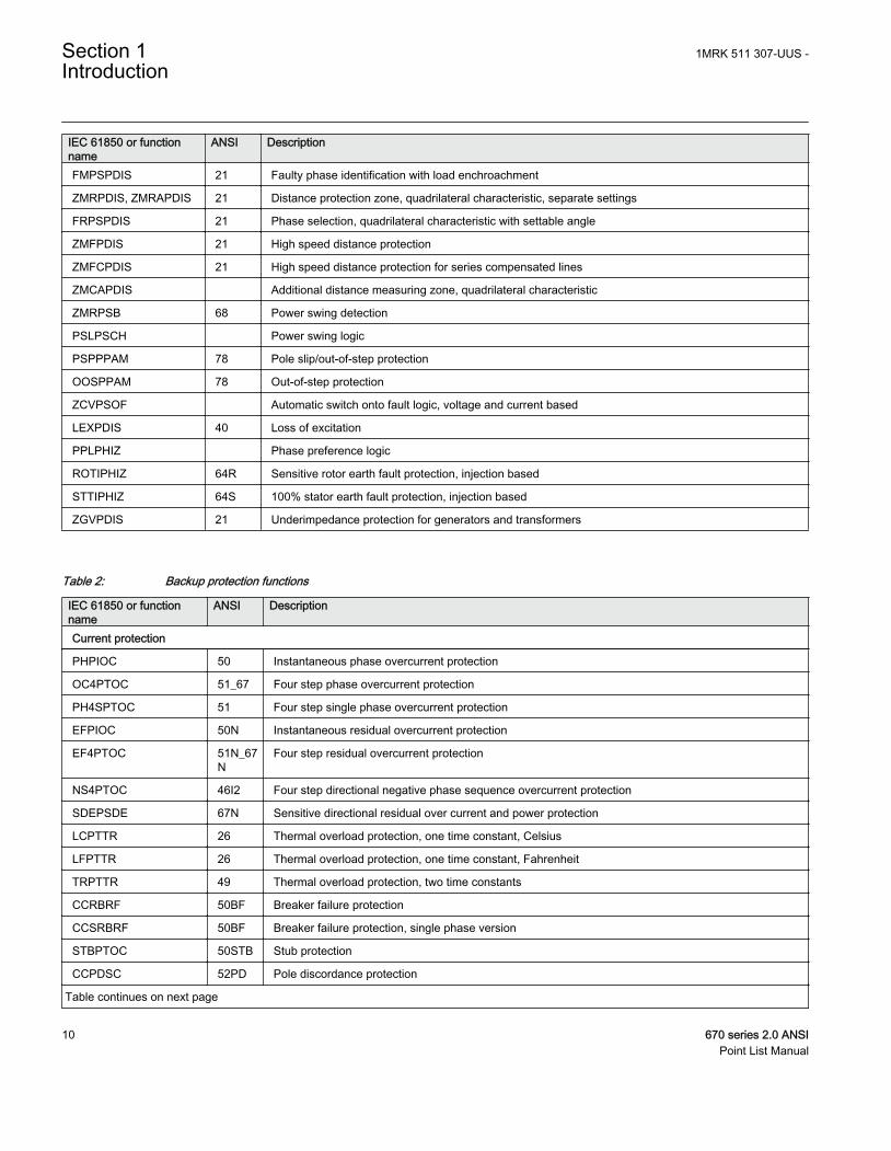
Table 2: Backup protection functions
IEC 61850 or functionname
ANSI Description
Current protection
PHPIOC 50 Instantaneous phase overcurrent protection
OC4PTOC 51_67 Four step phase overcurrent protection
PH4SPTOC 51 Four step single phase overcurrent protection
EFPIOC 50N Instantaneous residual overcurrent protection
EF4PTOC 51N_67N
Four step residual overcurrent protection
NS4PTOC 46I2 Four step directional negative phase sequence overcurrent protection
SDEPSDE 67N Sensitive directional residual over current and power protection
LCPTTR 26 Thermal overload protection, one time constant, Celsius
LFPTTR 26 Thermal overload protection, one time constant, Fahrenheit
TRPTTR 49 Thermal overload protection, two time constants
CCRBRF 50BF Breaker failure protection
CCSRBRF 50BF Breaker failure protection, single phase version
STBPTOC 50STB Stub protection
CCPDSC 52PD Pole discordance protection
Table continues on next page
Section 1 1MRK 511 307-UUS -Introduction
10 670 series 2.0 ANSIPoint List Manual
IEC 61850 or functionname
ANSI Description
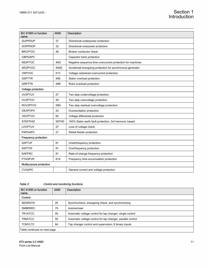
GUPPDUP 37 Directional underpower protection
GOPPDOP 32 Directional overpower protection
BRCPTOC 46 Broken conductor check
CBPGAPC Capacitor bank protection
NS2PTOC 46I2 Negative sequence time overcurrent protection for machines
AEGPVOC 50AE Accidental energizing protection for synchronous generator
VRPVOC 51V Voltage restrained overcurrent protection
GSPTTR 49S Stator overload protection
GRPTTR 49R Rotor overload protection
Voltage protection
UV2PTUV 27 Two step undervoltage protection
OV2PTOV 59 Two step overvoltage protection
ROV2PTOV 59N Two step residual overvoltage protection
OEXPVPH 24 Overexcitation protection
VDCPTOV 60 Voltage differential protection
STEFPHIZ 59THD 100% Stator earth fault protection, 3rd harmonic based
LOVPTUV 27 Loss of voltage check
PAPGAPC 27 Radial feeder protection
Frequency protection
SAPTUF 81 Underfrequency protection
SAPTOF 81 Overfrequency protection
SAPFRC 81 Rate-of-change frequency protection
FTAQFVR 81A Frequency time accumulation protection
Multipurpose protection
CVGAPC General current and voltage protection
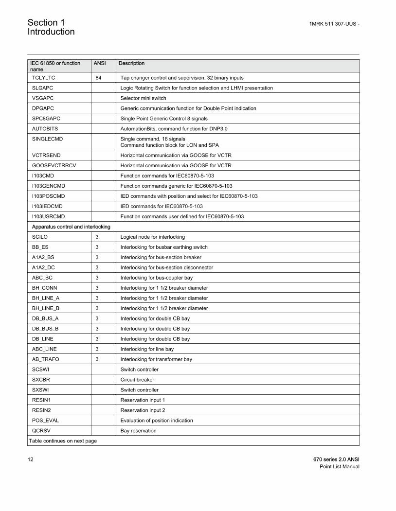
Table 3: Control and monitoring functions
IEC 61850 or functionname
ANSI Description
Control
SESRSYN 25 Synchrocheck, energizing check, and synchronizing
SMBRREC 79 Autorecloser
TR1ATCC 90 Automatic voltage control for tap changer, single control
TR8ATCC 90 Automatic voltage control for tap changer, parallel control
TCMYLTC 84 Tap changer control and supervision, 6 binary inputs
Table continues on next page
1MRK 511 307-UUS - Section 1Introduction
670 series 2.0 ANSI 11Point List Manual
IEC 61850 or functionname
ANSI Description
TCLYLTC 84 Tap changer control and supervision, 32 binary inputs
SLGAPC Logic Rotating Switch for function selection and LHMI presentation
VSGAPC Selector mini switch
DPGAPC Generic communication function for Double Point indication
SPC8GAPC Single Point Generic Control 8 signals
AUTOBITS AutomationBits, command function for DNP3.0
SINGLECMD Single command, 16 signalsCommand function block for LON and SPA
VCTRSEND Horizontal communication via GOOSE for VCTR
GOOSEVCTRRCV Horizontal communication via GOOSE for VCTR
I103CMD Function commands for IEC60870-5-103
I103GENCMD Function commands generic for IEC60870-5-103
I103POSCMD IED commands with position and select for IEC60870-5-103
I103IEDCMD IED commands for IEC60870-5-103
I103USRCMD Function commands user defined for IEC60870-5-103
Apparatus control and interlocking
SCILO 3 Logical node for interlocking
BB_ES 3 Interlocking for busbar earthing switch
A1A2_BS 3 Interlocking for bus-section breaker
A1A2_DC 3 Interlocking for bus-section disconnector
ABC_BC 3 Interlocking for bus-coupler bay
BH_CONN 3 Interlocking for 1 1/2 breaker diameter
BH_LINE_A 3 Interlocking for 1 1/2 breaker diameter
BH_LINE_B 3 Interlocking for 1 1/2 breaker diameter
DB_BUS_A 3 Interlocking for double CB bay
DB_BUS_B 3 Interlocking for double CB bay
DB_LINE 3 Interlocking for double CB bay
ABC_LINE 3 Interlocking for line bay
AB_TRAFO 3 Interlocking for transformer bay
SCSWI Switch controller
SXCBR Circuit breaker
SXSWI Switch controller
RESIN1 Reservation input 1
RESIN2 Reservation input 2
POS_EVAL Evaluation of position indication
QCRSV Bay reservation
Table continues on next page
Section 1 1MRK 511 307-UUS -Introduction
12 670 series 2.0 ANSIPoint List Manual
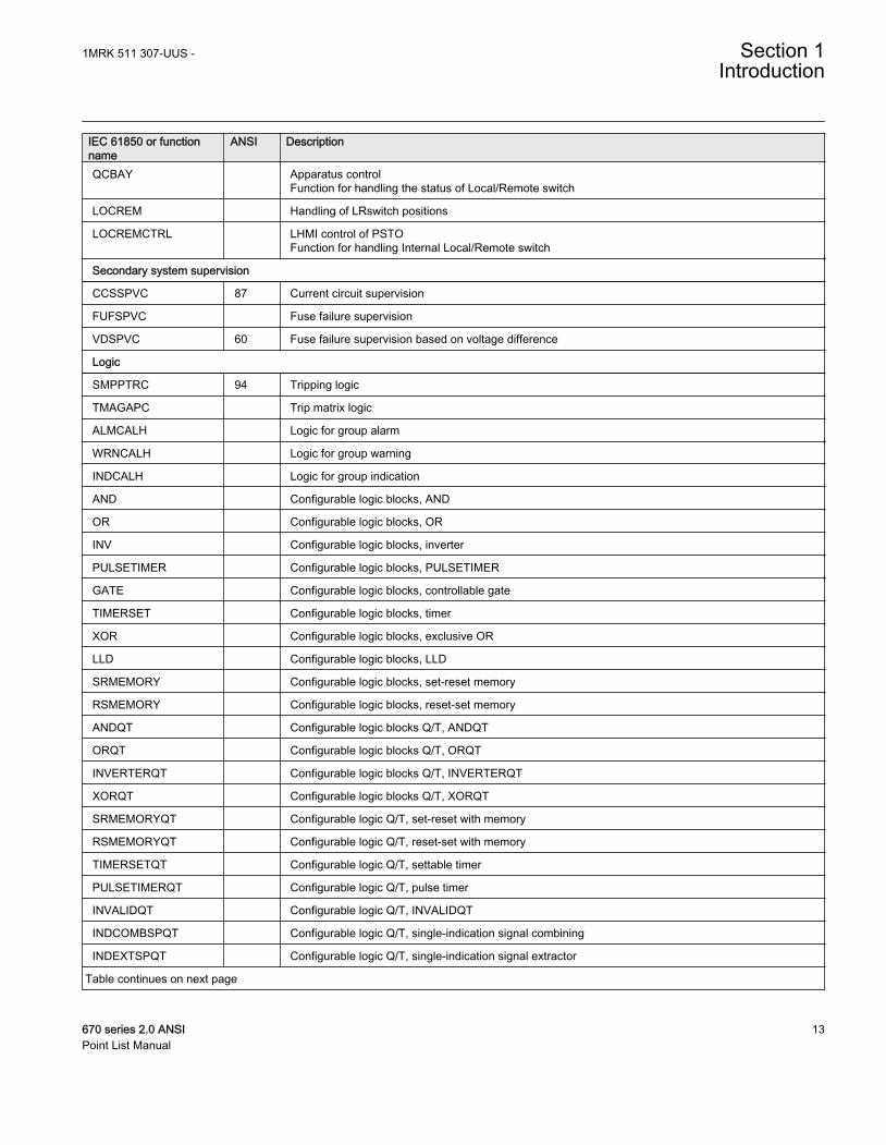
IEC 61850 or functionname
ANSI Description
QCBAY Apparatus controlFunction for handling the status of Local/Remote switch
LOCREM Handling of LRswitch positions
LOCREMCTRL LHMI control of PSTOFunction for handling Internal Local/Remote switch
Secondary system supervision
CCSSPVC 87 Current circuit supervision
FUFSPVC Fuse failure supervision
VDSPVC 60 Fuse failure supervision based on voltage difference
Logic
SMPPTRC 94 Tripping logic
TMAGAPC Trip matrix logic
ALMCALH Logic for group alarm
WRNCALH Logic for group warning
INDCALH Logic for group indication
AND Configurable logic blocks, AND
OR Configurable logic blocks, OR
INV Configurable logic blocks, inverter
PULSETIMER Configurable logic blocks, PULSETIMER
GATE Configurable logic blocks, controllable gate
TIMERSET Configurable logic blocks, timer
XOR Configurable logic blocks, exclusive OR
LLD Configurable logic blocks, LLD
SRMEMORY Configurable logic blocks, set-reset memory
RSMEMORY Configurable logic blocks, reset-set memory
ANDQT Configurable logic blocks Q/T, ANDQT
ORQT Configurable logic blocks Q/T, ORQT
INVERTERQT Configurable logic blocks Q/T, INVERTERQT
XORQT Configurable logic blocks Q/T, XORQT
SRMEMORYQT Configurable logic Q/T, set-reset with memory
RSMEMORYQT Configurable logic Q/T, reset-set with memory
TIMERSETQT Configurable logic Q/T, settable timer
PULSETIMERQT Configurable logic Q/T, pulse timer
INVALIDQT Configurable logic Q/T, INVALIDQT
INDCOMBSPQT Configurable logic Q/T, single-indication signal combining
INDEXTSPQT Configurable logic Q/T, single-indication signal extractor
Table continues on next page
1MRK 511 307-UUS - Section 1Introduction
670 series 2.0 ANSI 13Point List Manual
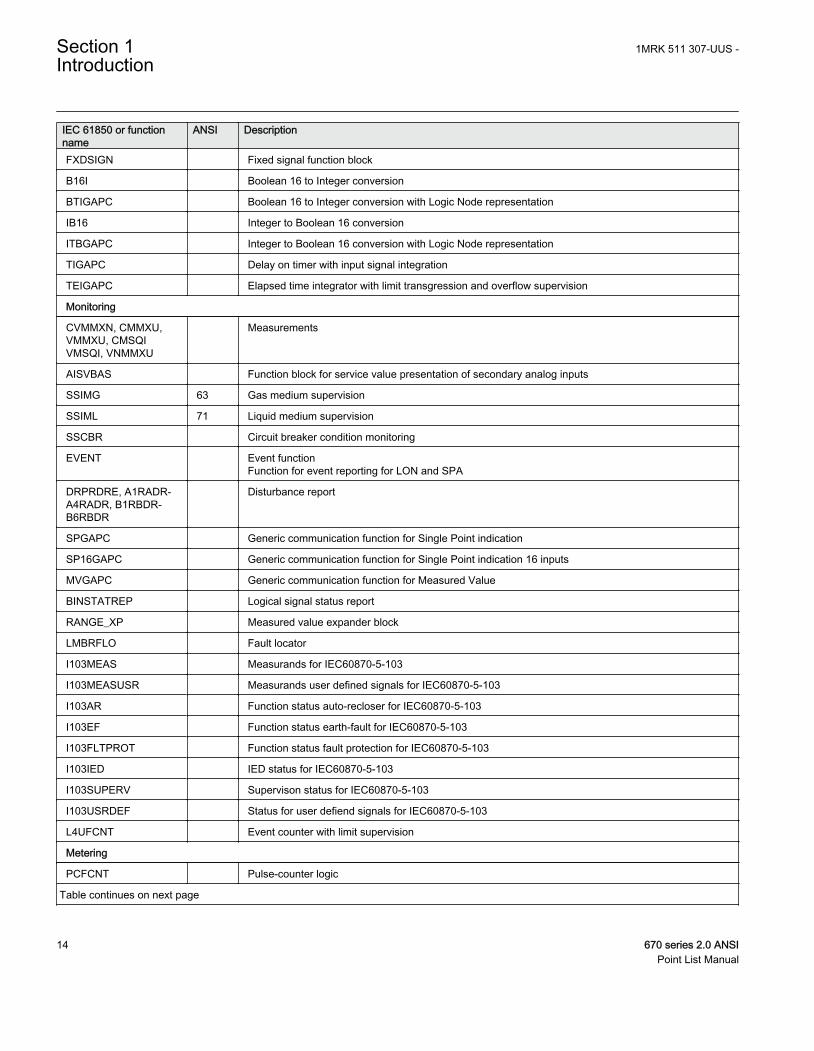
IEC 61850 or functionname
ANSI Description
FXDSIGN Fixed signal function block
B16I Boolean 16 to Integer conversion
BTIGAPC Boolean 16 to Integer conversion with Logic Node representation
IB16 Integer to Boolean 16 conversion
ITBGAPC Integer to Boolean 16 conversion with Logic Node representation
TIGAPC Delay on timer with input signal integration
TEIGAPC Elapsed time integrator with limit transgression and overflow supervision
Monitoring
CVMMXN, CMMXU,VMMXU, CMSQIVMSQI, VNMMXU
Measurements
AISVBAS Function block for service value presentation of secondary analog inputs
SSIMG 63 Gas medium supervision
SSIML 71 Liquid medium supervision
SSCBR Circuit breaker condition monitoring
EVENT Event functionFunction for event reporting for LON and SPA
DRPRDRE, A1RADR-A4RADR, B1RBDR-B6RBDR
Disturbance report
SPGAPC Generic communication function for Single Point indication
SP16GAPC Generic communication function for Single Point indication 16 inputs
MVGAPC Generic communication function for Measured Value
BINSTATREP Logical signal status report
RANGE_XP Measured value expander block
LMBRFLO Fault locator
I103MEAS Measurands for IEC60870-5-103
I103MEASUSR Measurands user defined signals for IEC60870-5-103
I103AR Function status auto-recloser for IEC60870-5-103
I103EF Function status earth-fault for IEC60870-5-103
I103FLTPROT Function status fault protection for IEC60870-5-103
I103IED IED status for IEC60870-5-103
I103SUPERV Supervison status for IEC60870-5-103
I103USRDEF Status for user defiend signals for IEC60870-5-103
L4UFCNT Event counter with limit supervision
Metering
PCFCNT Pulse-counter logic
Table continues on next page
Section 1 1MRK 511 307-UUS -Introduction
14 670 series 2.0 ANSIPoint List Manual
IEC 61850 or functionname
ANSI Description
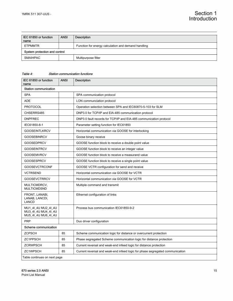
ETPMMTR Function for energy calculation and demand handling
System protection and control
SMAIHPAC Multipurpose filter
Table 4: Station communication functions
IEC 61850 or functionname
ANSI Description
Station communication
SPA SPA communication protocol
ADE LON communciation protocol
PROTOCOL Operation selection between SPA and IEC60870-5-103 for SLM
CHSERRS485 DNP3.0 for TCP/IP and EIA-485 communication protocol
DNPFREC DNP3.0 fault records for TCP/IP and EIA-485 communication protocol
IEC61850-8-1 Parameter setting function for IEC61850
GOOSEINTLKRCV Horizontal communication via GOOSE for interlocking
GOOSEBINRCV Goose binary receive
GOOSEDPRCV GOOSE function block to receive a double point value
GOOSEINTRCV GOOSE function block to receive an integer value
GOOSEMVRCV GOOSE function block to receive a measurand value
GOOSESPRCV GOOSE function block to receive a single point value
GOOSEVCTRCONF GOOSE VCTR configuration for send and receive
VCTRSEND Horizontal communication via GOOSE for VCTR
GOOSEVCTRRCV Horizontal communication via GOOSE for VCTR
MULTICMDRCV,MULTICMDSND
Multiple command and transmit
FRONT, LANABI,LANAB, LANCDI,LANCD
Ethernet configuration of links
MU1_4I_4U MU2_4I_4UMU3_4I_4U MU4_4I_4UMU5_4I_4U MU6_4I_4U
Process bus communication IEC61850-9-2
PRP Duo driver configuration
Scheme communication
ZCPSCH 85 Scheme communication logic for distance or overcurrent protection
ZC1PPSCH 85 Phase segregated Scheme communication logic for distance protection
ZCRWPSCH 85 Current reversal and weak-end infeed logic for distance protection
ZC1WPSCH 85 Current reversal and weak-end infeed logic for phase segregated communication
Table continues on next page
1MRK 511 307-UUS - Section 1Introduction
670 series 2.0 ANSI 15Point List Manual
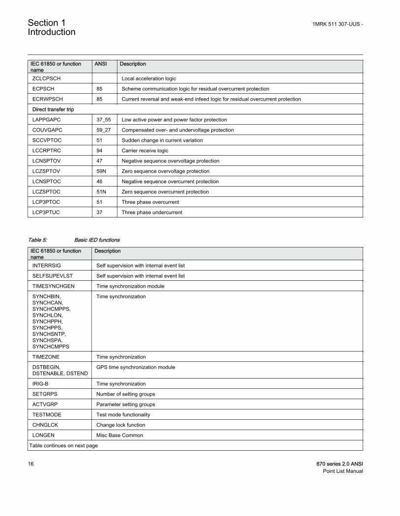
IEC 61850 or functionname
ANSI Description
ZCLCPSCH Local acceleration logic
ECPSCH 85 Scheme communication logic for residual overcurrent protection
ECRWPSCH 85 Current reversal and weak-end infeed logic for residual overcurrent protection
Direct transfer trip
LAPPGAPC 37_55 Low active power and power factor protection
COUVGAPC 59_27 Compensated over- and undervoltage protection
SCCVPTOC 51 Sudden change in current variation
LCCRPTRC 94 Carrier receive logic
LCNSPTOV 47 Negative sequence overvoltage protection
LCZSPTOV 59N Zero sequence overvoltage protection
LCNSPTOC 46 Negative sequence overcurrent protection
LCZSPTOC 51N Zero sequence overcurrent protection
LCP3PTOC 51 Three phase overcurrent
LCP3PTUC 37 Three phase undercurrent
Table 5: Basic IED functions
IEC 61850 or functionname
Description
INTERRSIG Self supervision with internal event list
SELFSUPEVLST Self supervision with internal event list
TIMESYNCHGEN Time synchronization module
SYNCHBIN,SYNCHCAN,SYNCHCMPPS,SYNCHLON,SYNCHPPH,SYNCHPPS,SYNCHSNTP,SYNCHSPA,SYNCHCMPPS
Time synchronization
TIMEZONE Time synchronization
DSTBEGIN,DSTENABLE, DSTEND
GPS time synchronization module
IRIG-B Time synchronization
SETGRPS Number of setting groups
ACTVGRP Parameter setting groups
TESTMODE Test mode functionality
CHNGLCK Change lock function
LONGEN Misc Base Common
Table continues on next page
Section 1 1MRK 511 307-UUS -Introduction
16 670 series 2.0 ANSIPoint List Manual
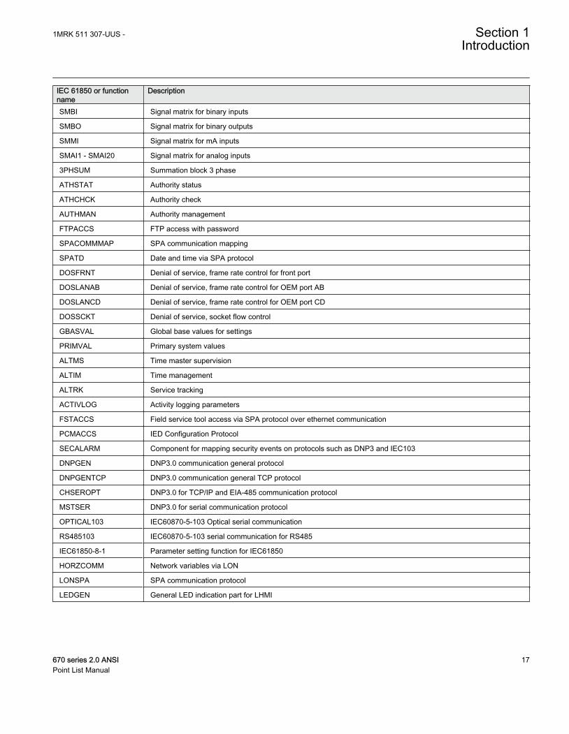
IEC 61850 or functionname
Description
SMBI Signal matrix for binary inputs
SMBO Signal matrix for binary outputs
SMMI Signal matrix for mA inputs
SMAI1 - SMAI20 Signal matrix for analog inputs
3PHSUM Summation block 3 phase
ATHSTAT Authority status
ATHCHCK Authority check
AUTHMAN Authority management
FTPACCS FTP access with password
SPACOMMMAP SPA communication mapping
SPATD Date and time via SPA protocol
DOSFRNT Denial of service, frame rate control for front port
DOSLANAB Denial of service, frame rate control for OEM port AB
DOSLANCD Denial of service, frame rate control for OEM port CD
DOSSCKT Denial of service, socket flow control
GBASVAL Global base values for settings
PRIMVAL Primary system values
ALTMS Time master supervision
ALTIM Time management
ALTRK Service tracking
ACTIVLOG Activity logging parameters
FSTACCS Field service tool access via SPA protocol over ethernet communication
PCMACCS IED Configuration Protocol
SECALARM Component for mapping security events on protocols such as DNP3 and IEC103
DNPGEN DNP3.0 communication general protocol
DNPGENTCP DNP3.0 communication general TCP protocol
CHSEROPT DNP3.0 for TCP/IP and EIA-485 communication protocol
MSTSER DNP3.0 for serial communication protocol
OPTICAL103 IEC60870-5-103 Optical serial communication
RS485103 IEC60870-5-103 serial communication for RS485
IEC61850-8-1 Parameter setting function for IEC61850
HORZCOMM Network variables via LON
LONSPA SPA communication protocol
LEDGEN General LED indication part for LHMI
1MRK 511 307-UUS - Section 1Introduction
670 series 2.0 ANSI 17Point List Manual

18
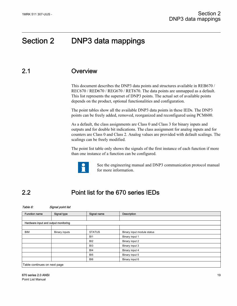
Section 2 DNP3 data mappings
2.1 Overview
This document describes the DNP3 data points and structures available in REB670 /REC670 / RED670 / REG670 / RET670. The data points are unmapped as a default.This list represents the superset of DNP3 points. The actual set of available pointsdepends on the product, optional functionalities and configuration.
The point tables show all the available DNP3 data points in these IEDs. The DNP3points can be freely added, removed, reorganized and reconfigured using PCM600.
As a default, the class assignments are Class 0 and Class 3 for binary inputs andoutputs and for double bit indications. The class assignment for analog inputs and forcounters are Class 0 and Class 2. Analog values are provided with default scalings. Thescalings can be freely modified.
The point list table only shows the signals of the first instance of each function if morethan one instance of a function can be configured.
See the engineering manual and DNP3 communication protocol manualfor more information.
2.2 Point list for the 670 series IEDs
Table 6: Signal point list
Function name Signal type Signal name Description Hardware input and output monitoring BIM Binary inputs STATUS Binary input module status BI1 Binary input 1 BI2 Binary input 2 BI3 Binary input 3 BI4 Binary input 4 BI5 Binary input 5 BI6 Binary input 6
Table continues on next page
1MRK 511 307-UUS - Section 2DNP3 data mappings
670 series 2.0 ANSI 19Point List Manual
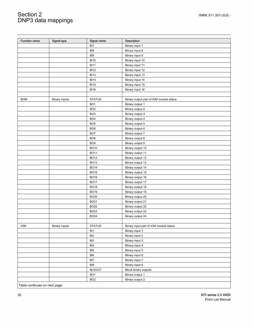
Function name Signal type Signal name Description BI7 Binary input 7 BI8 Binary input 8 BI9 Binary input 9 BI10 Binary input 10 BI11 Binary input 11 BI12 Binary input 12 BI13 Binary input 13 BI14 Binary input 14 BI15 Binary input 15 BI16 Binary input 16 BOM Binary inputs STATUS Binary output part of IOM module status BO1 Binary output 1 BO2 Binary output 2 BO3 Binary output 3 BO4 Binary output 4 BO5 Binary output 5 BO6 Binary output 6 BO7 Binary output 7 BO8 Binary output 8 BO9 Binary output 9 BO10 Binary output 10 BO11 Binary output 11 BO12 Binary output 12 BO13 Binary output 13 BO14 Binary output 14 BO15 Binary output 15 BO16 Binary output 16 BO17 Binary output 17 BO18 Binary output 18 BO19 Binary output 19 BO20 Binary output 20 BO21 Binary output 21 BO22 Binary output 22 BO23 Binary output 23 BO24 Binary output 24 IOM Binary inputs STATUS Binary input part of IOM module status BI1 Binary input 1 BI2 Binary input 2 BI3 Binary input 3 BI4 Binary input 4 BI5 Binary input 5 BI6 Binary input 6 BI7 Binary input 7 BI8 Binary input 8 BLKOUT Block binary outputs BO1 Binary output 1 BO2 Binary output 2
Table continues on next page
Section 2 1MRK 511 307-UUS -DNP3 data mappings
20 670 series 2.0 ANSIPoint List Manual
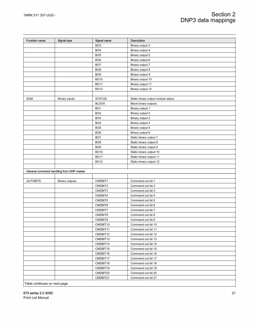
Function name Signal type Signal name Description BO3 Binary output 3 BO4 Binary output 4 BO5 Binary output 5 BO6 Binary output 6 BO7 Binary output 7 BO8 Binary output 8 BO9 Binary output 9 BO10 Binary output 10 BO11 Binary output 11 BO12 Binary output 12 SOM Binary inputs STATUS Static binary output module status BLOCK Block binary outputs BO1 Binary output 1 BO2 Binary output 2 BO3 Binary output 3 BO4 Binary output 4 BO5 Binary output 5 BO6 Binary output 6 BO7 Static binary output 7 BO8 Static binary output 8 BO9 Static binary output 9 BO10 Static binary output 10 BO11 Static binary output 11 BO12 Static binary output 12 General command handling from DNP master AUTOBITS Binary outputs CMDBIT1 Command out bit 1 CMDBIT2 Command out bit 2 CMDBIT3 Command out bit 3 CMDBIT4 Command out bit 4 CMDBIT5 Command out bit 5 CMDBIT6 Command out bit 6 CMDBIT7 Command out bit 7 CMDBIT8 Command out bit 8 CMDBIT9 Command out bit 9 CMDBIT10 Command out bit 10 CMDBIT11 Command out bit 11 CMDBIT12 Command out bit 12 CMDBIT13 Command out bit 13 CMDBIT14 Command out bit 14 CMDBIT15 Command out bit 15 CMDBIT16 Command out bit 16 CMDBIT17 Command out bit 17 CMDBIT18 Command out bit 18 CMDBIT19 Command out bit 19 CMDBIT20 Command out bit 20 CMDBIT21 Command out bit 21
Table continues on next page
1MRK 511 307-UUS - Section 2DNP3 data mappings
670 series 2.0 ANSI 21Point List Manual
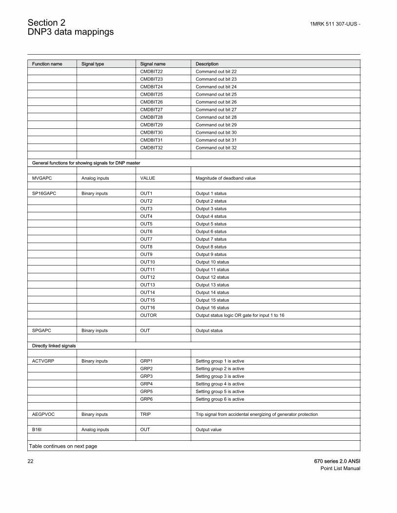
Function name Signal type Signal name Description CMDBIT22 Command out bit 22 CMDBIT23 Command out bit 23 CMDBIT24 Command out bit 24 CMDBIT25 Command out bit 25 CMDBIT26 Command out bit 26 CMDBIT27 Command out bit 27 CMDBIT28 Command out bit 28 CMDBIT29 Command out bit 29 CMDBIT30 Command out bit 30 CMDBIT31 Command out bit 31 CMDBIT32 Command out bit 32 General functions for showing signals for DNP master MVGAPC Analog inputs VALUE Magnitude of deadband value SP16GAPC Binary inputs OUT1 Output 1 status OUT2 Output 2 status OUT3 Output 3 status OUT4 Output 4 status OUT5 Output 5 status OUT6 Output 6 status OUT7 Output 7 status OUT8 Output 8 status OUT9 Output 9 status OUT10 Output 10 status OUT11 Output 11 status OUT12 Output 12 status OUT13 Output 13 status OUT14 Output 14 status OUT15 Output 15 status OUT16 Output 16 status OUTOR Output status logic OR gate for input 1 to 16 SPGAPC Binary inputs OUT Output status Directly linked signals ACTVGRP Binary inputs GRP1 Setting group 1 is active GRP2 Setting group 2 is active GRP3 Setting group 3 is active GRP4 Setting group 4 is active GRP5 Setting group 5 is active GRP6 Setting group 6 is active AEGPVOC Binary inputs TRIP Trip signal from accidental energizing of generator protection B16I Analog inputs OUT Output value
Table continues on next page
Section 2 1MRK 511 307-UUS -DNP3 data mappings
22 670 series 2.0 ANSIPoint List Manual
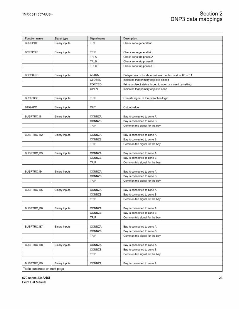
Function name Signal type Signal name DescriptionBCZSPDIF Binary inputs TRIP Check zone general trip BCZTPDIF Binary inputs TRIP Check zone general trip TR_A Check zone trip phase A TR_B Check zone trip phase B TR_C Check zone trip phase C BDCGAPC Binary inputs ALARM Delayed alarm for abnormal aux. contact status, 00 or 11 CLOSED Indicates that primary object is closed FORCED Primary object status forced to open or closed by setting OPEN Indicates that primary object is open BRCPTOC Binary inputs TRIP Operate signal of the protection logic BTIGAPC Binary inputs OUT Output value BUSPTRC_B1 Binary inputs CONNZA Bay is connected to zone A CONNZB Bay is connected to zone B TRIP Common trip signal for the bay BUSPTRC_B2 Binary inputs CONNZA Bay is connected to zone A CONNZB Bay is connected to zone B TRIP Common trip signal for the bay BUSPTRC_B3 Binary inputs CONNZA Bay is connected to zone A CONNZB Bay is connected to zone B TRIP Common trip signal for the bay BUSPTRC_B4 Binary inputs CONNZA Bay is connected to zone A CONNZB Bay is connected to zone B TRIP Common trip signal for the bay BUSPTRC_B5 Binary inputs CONNZA Bay is connected to zone A CONNZB Bay is connected to zone B TRIP Common trip signal for the bay BUSPTRC_B6 Binary inputs CONNZA Bay is connected to zone A CONNZB Bay is connected to zone B TRIP Common trip signal for the bay BUSPTRC_B7 Binary inputs CONNZA Bay is connected to zone A CONNZB Bay is connected to zone B TRIP Common trip signal for the bay BUSPTRC_B8 Binary inputs CONNZA Bay is connected to zone A CONNZB Bay is connected to zone B TRIP Common trip signal for the bay BUSPTRC_B9 Binary inputs CONNZA Bay is connected to zone A
Table continues on next page
1MRK 511 307-UUS - Section 2DNP3 data mappings
670 series 2.0 ANSI 23Point List Manual
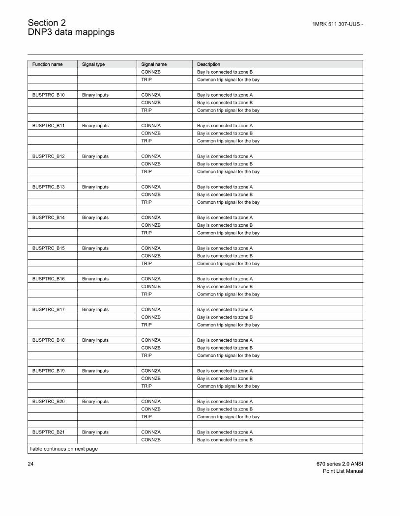
Function name Signal type Signal name Description CONNZB Bay is connected to zone B TRIP Common trip signal for the bay BUSPTRC_B10 Binary inputs CONNZA Bay is connected to zone A CONNZB Bay is connected to zone B TRIP Common trip signal for the bay BUSPTRC_B11 Binary inputs CONNZA Bay is connected to zone A CONNZB Bay is connected to zone B TRIP Common trip signal for the bay BUSPTRC_B12 Binary inputs CONNZA Bay is connected to zone A CONNZB Bay is connected to zone B TRIP Common trip signal for the bay BUSPTRC_B13 Binary inputs CONNZA Bay is connected to zone A CONNZB Bay is connected to zone B TRIP Common trip signal for the bay BUSPTRC_B14 Binary inputs CONNZA Bay is connected to zone A CONNZB Bay is connected to zone B TRIP Common trip signal for the bay BUSPTRC_B15 Binary inputs CONNZA Bay is connected to zone A CONNZB Bay is connected to zone B TRIP Common trip signal for the bay BUSPTRC_B16 Binary inputs CONNZA Bay is connected to zone A CONNZB Bay is connected to zone B TRIP Common trip signal for the bay BUSPTRC_B17 Binary inputs CONNZA Bay is connected to zone A CONNZB Bay is connected to zone B TRIP Common trip signal for the bay BUSPTRC_B18 Binary inputs CONNZA Bay is connected to zone A CONNZB Bay is connected to zone B TRIP Common trip signal for the bay BUSPTRC_B19 Binary inputs CONNZA Bay is connected to zone A CONNZB Bay is connected to zone B TRIP Common trip signal for the bay BUSPTRC_B20 Binary inputs CONNZA Bay is connected to zone A CONNZB Bay is connected to zone B TRIP Common trip signal for the bay BUSPTRC_B21 Binary inputs CONNZA Bay is connected to zone A CONNZB Bay is connected to zone B
Table continues on next page
Section 2 1MRK 511 307-UUS -DNP3 data mappings
24 670 series 2.0 ANSIPoint List Manual
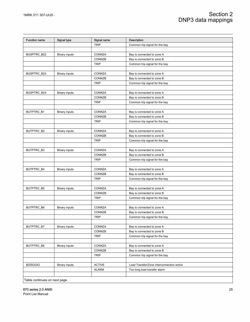
Function name Signal type Signal name Description TRIP Common trip signal for the bay BUSPTRC_B22 Binary inputs CONNZA Bay is connected to zone A CONNZB Bay is connected to zone B TRIP Common trip signal for the bay BUSPTRC_B23 Binary inputs CONNZA Bay is connected to zone A CONNZB Bay is connected to zone B TRIP Common trip signal for the bay BUSPTRC_B24 Binary inputs CONNZA Bay is connected to zone A CONNZB Bay is connected to zone B TRIP Common trip signal for the bay BUTPTRC_B1 Binary inputs CONNZA Bay is connected to zone A CONNZB Bay is connected to zone B TRIP Common trip signal for the bay BUTPTRC_B2 Binary inputs CONNZA Bay is connected to zone A CONNZB Bay is connected to zone B TRIP Common trip signal for the bay BUTPTRC_B3 Binary inputs CONNZA Bay is connected to zone A CONNZB Bay is connected to zone B TRIP Common trip signal for the bay BUTPTRC_B4 Binary inputs CONNZA Bay is connected to zone A CONNZB Bay is connected to zone B TRIP Common trip signal for the bay BUTPTRC_B5 Binary inputs CONNZA Bay is connected to zone A CONNZB Bay is connected to zone B TRIP Common trip signal for the bay BUTPTRC_B6 Binary inputs CONNZA Bay is connected to zone A CONNZB Bay is connected to zone B TRIP Common trip signal for the bay BUTPTRC_B7 Binary inputs CONNZA Bay is connected to zone A CONNZB Bay is connected to zone B TRIP Common trip signal for the bay BUTPTRC_B8 Binary inputs CONNZA Bay is connected to zone A CONNZB Bay is connected to zone B TRIP Common trip signal for the bay BZISGGIO Binary inputs ACTIVE Load Transfer/Zone Interconnection active ALARM Too long load transfer alarm
Table continues on next page
1MRK 511 307-UUS - Section 2DNP3 data mappings
670 series 2.0 ANSI 25Point List Manual
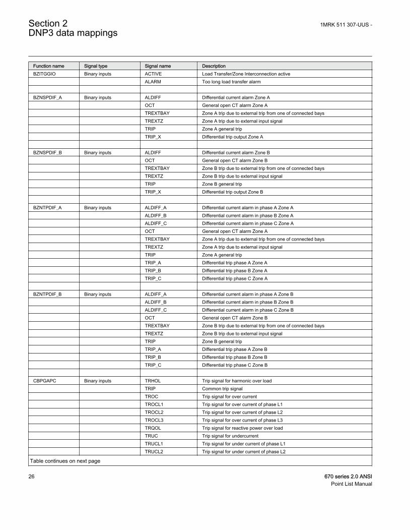
Function name Signal type Signal name DescriptionBZITGGIO Binary inputs ACTIVE Load Transfer/Zone Interconnection active ALARM Too long load transfer alarm BZNSPDIF_A Binary inputs ALDIFF Differential current alarm Zone A OCT General open CT alarm Zone A TREXTBAY Zone A trip due to external trip from one of connected bays TREXTZ Zone A trip due to external input signal TRIP Zone A general trip TRIP_X Differential trip output Zone A BZNSPDIF_B Binary inputs ALDIFF Differential current alarm Zone B OCT General open CT alarm Zone B TREXTBAY Zone B trip due to external trip from one of connected bays TREXTZ Zone B trip due to external input signal TRIP Zone B general trip TRIP_X Differential trip output Zone B BZNTPDIF_A Binary inputs ALDIFF_A Differential current alarm in phase A Zone A ALDIFF_B Differential current alarm in phase B Zone A ALDIFF_C Differential current alarm in phase C Zone A OCT General open CT alarm Zone A TREXTBAY Zone A trip due to external trip from one of connected bays TREXTZ Zone A trip due to external input signal TRIP Zone A general trip TRIP_A Differential trip phase A Zone A TRIP_B Differential trip phase B Zone A TRIP_C Differential trip phase C Zone A BZNTPDIF_B Binary inputs ALDIFF_A Differential current alarm in phase A Zone B ALDIFF_B Differential current alarm in phase B Zone B ALDIFF_C Differential current alarm in phase C Zone B OCT General open CT alarm Zone B TREXTBAY Zone B trip due to external trip from one of connected bays TREXTZ Zone B trip due to external input signal TRIP Zone B general trip TRIP_A Differential trip phase A Zone B TRIP_B Differential trip phase B Zone B TRIP_C Differential trip phase C Zone B CBPGAPC Binary inputs TRHOL Trip signal for harmonic over load TRIP Common trip signal TROC Trip signal for over current TROCL1 Trip signal for over current of phase L1 TROCL2 Trip signal for over current of phase L2 TROCL3 Trip signal for over current of phase L3 TRQOL Trip signal for reactive power over load TRUC Trip signal for undercurrent TRUCL1 Trip signal for under current of phase L1 TRUCL2 Trip signal for under current of phase L2
Table continues on next page
Section 2 1MRK 511 307-UUS -DNP3 data mappings
26 670 series 2.0 ANSIPoint List Manual
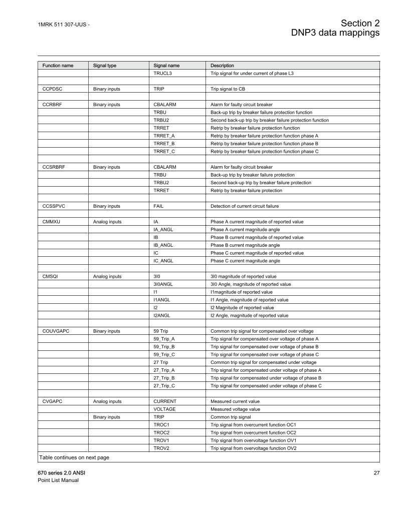
Function name Signal type Signal name Description TRUCL3 Trip signal for under current of phase L3 CCPDSC Binary inputs TRIP Trip signal to CB CCRBRF Binary inputs CBALARM Alarm for faulty circuit breaker TRBU Back-up trip by breaker failure protection function TRBU2 Second back-up trip by breaker failure protection function TRRET Retrip by breaker failure protection function TRRET_A Retrip by breaker failure protection function phase A TRRET_B Retrip by breaker failure protection function phase B TRRET_C Retrip by breaker failure protection function phase C CCSRBRF Binary inputs CBALARM Alarm for faulty circuit breaker TRBU Back-up trip by breaker failure protection TRBU2 Second back-up trip by breaker failure protection TRRET Retrip by breaker failure protection CCSSPVC Binary inputs FAIL Detection of current circuit failure CMMXU Analog inputs IA Phase A current magnitude of reported value IA_ANGL Phase A current magnitude angle IB Phase B current magnitude of reported value IB_ANGL Phase B current magnitude angle IC Phase C current magnitude of reported value IC_ANGL Phase C current magnitude angle CMSQI Analog inputs 3I0 3I0 magnitude of reported value 3I0ANGL 3I0 Angle, magnitude of reported value I1 I1magnitude of reported value I1ANGL I1 Angle, magnitude of reported value I2 I2 Magnitude of reported value I2ANGL I2 Angle, magnitude of reported value COUVGAPC Binary inputs 59 Trip Common trip signal for compensated over voltage 59_Trip_A Trip signal for compensated over voltage of phase A 59_Trip_B Trip signal for compensated over voltage of phase B 59_Trip_C Trip signal for compensated over voltage of phase C 27 Trip Common trip signal for compensated under voltage 27_Trip_A Trip signal for compensated under voltage of phase A 27_Trip_B Trip signal for compensated under voltage of phase B 27_Trip_C Trip signal for compensated under voltage of phase C CVGAPC Analog inputs CURRENT Measured current value VOLTAGE Measured voltage value Binary inputs TRIP Common trip signal TROC1 Trip signal from overcurrent function OC1 TROC2 Trip signal from overcurrent function OC2 TROV1 Trip signal from overvoltage function OV1 TROV2 Trip signal from overvoltage function OV2
Table continues on next page
1MRK 511 307-UUS - Section 2DNP3 data mappings
670 series 2.0 ANSI 27Point List Manual
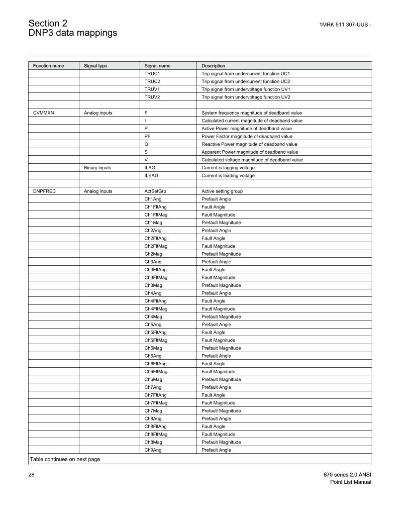
Function name Signal type Signal name Description TRUC1 Trip signal from undercurrent function UC1 TRUC2 Trip signal from undercurrent function UC2 TRUV1 Trip signal from undervoltage function UV1 TRUV2 Trip signal from undervoltage function UV2 CVMMXN Analog inputs F System frequency magnitude of deadband value I Calculated current magnitude of deadband value P Active Power magnitude of deadband value PF Power Factor magnitude of deadband value Q Reactive Power magnitude of deadband value S Apparent Power magnitude of deadband value V Calculated voltage magnitude of deadband value Binary inputs ILAG Current is lagging voltage ILEAD Current is leading voltage DNPFREC Analog inputs ActSetGrp Active setting group Ch1Ang Prefault Angle Ch1FltAng Fault Angle Ch1FltMag Fault Magnitude Ch1Mag Prefault Magnitude Ch2Ang Prefault Angle Ch2FltAng Fault Angle Ch2FltMag Fault Magnitude Ch2Mag Prefault Magnitude Ch3Ang Prefault Angle Ch3FltAng Fault Angle Ch3FltMag Fault Magnitude Ch3Mag Prefault Magnitude Ch4Ang Prefault Angle Ch4FltAng Fault Angle Ch4FltMag Fault Magnitude Ch4Mag Prefault Magnitude Ch5Ang Prefault Angle Ch5FltAng Fault Angle Ch5FltMag Fault Magnitude Ch5Mag Prefault Magnitude Ch6Ang Prefault Angle Ch6FltAng Fault Angle Ch6FltMag Fault Magnitude Ch6Mag Prefault Magnitude Ch7Ang Prefault Angle Ch7FltAng Fault Angle Ch7FltMag Fault Magnitude Ch7Mag Prefault Magnitude Ch8Ang Prefault Angle Ch8FltAng Fault Angle Ch8FltMag Fault Magnitude Ch8Mag Prefault Magnitude Ch9Ang Prefault Angle
Table continues on next page
Section 2 1MRK 511 307-UUS -DNP3 data mappings
28 670 series 2.0 ANSIPoint List Manual
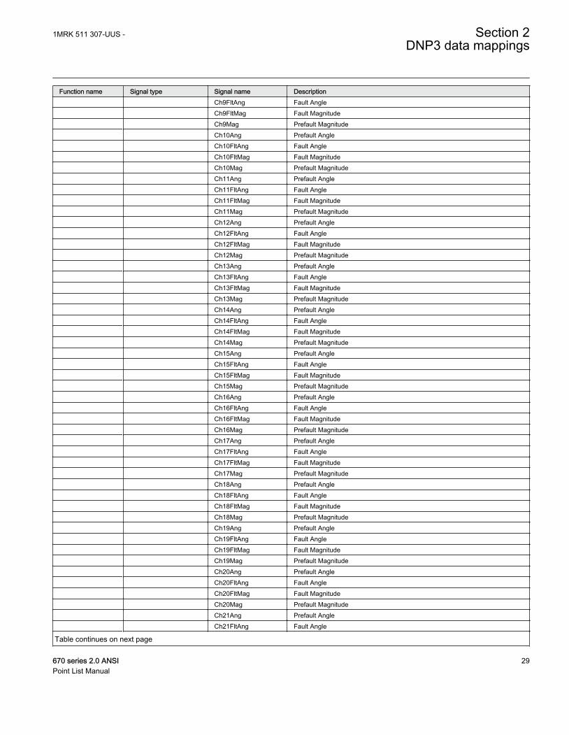
Function name Signal type Signal name Description Ch9FltAng Fault Angle Ch9FltMag Fault Magnitude Ch9Mag Prefault Magnitude Ch10Ang Prefault Angle Ch10FltAng Fault Angle Ch10FltMag Fault Magnitude Ch10Mag Prefault Magnitude Ch11Ang Prefault Angle Ch11FltAng Fault Angle Ch11FltMag Fault Magnitude Ch11Mag Prefault Magnitude Ch12Ang Prefault Angle Ch12FltAng Fault Angle Ch12FltMag Fault Magnitude Ch12Mag Prefault Magnitude Ch13Ang Prefault Angle Ch13FltAng Fault Angle Ch13FltMag Fault Magnitude Ch13Mag Prefault Magnitude Ch14Ang Prefault Angle Ch14FltAng Fault Angle Ch14FltMag Fault Magnitude Ch14Mag Prefault Magnitude Ch15Ang Prefault Angle Ch15FltAng Fault Angle Ch15FltMag Fault Magnitude Ch15Mag Prefault Magnitude Ch16Ang Prefault Angle Ch16FltAng Fault Angle Ch16FltMag Fault Magnitude Ch16Mag Prefault Magnitude Ch17Ang Prefault Angle Ch17FltAng Fault Angle Ch17FltMag Fault Magnitude Ch17Mag Prefault Magnitude Ch18Ang Prefault Angle Ch18FltAng Fault Angle Ch18FltMag Fault Magnitude Ch18Mag Prefault Magnitude Ch19Ang Prefault Angle Ch19FltAng Fault Angle Ch19FltMag Fault Magnitude Ch19Mag Prefault Magnitude Ch20Ang Prefault Angle Ch20FltAng Fault Angle Ch20FltMag Fault Magnitude Ch20Mag Prefault Magnitude Ch21Ang Prefault Angle Ch21FltAng Fault Angle
Table continues on next page
1MRK 511 307-UUS - Section 2DNP3 data mappings
670 series 2.0 ANSI 29Point List Manual

Function name Signal type Signal name Description Ch21FltMag Fault Magnitude Ch21Mag Prefault Magnitude Ch22Ang Prefault Angle Ch22FltAng Fault Angle Ch22FltMag Fault Magnitude Ch22Mag Prefault Magnitude Ch23Ang Prefault Angle Ch23FltAng Fault Angle Ch23FltMag Fault Magnitude Ch23Mag Prefault Magnitude Ch24Ang Prefault Angle Ch24FltAng Fault Angle Ch24FltMag Fault Magnitude Ch24Mag Prefault Magnitude Ch25Ang Prefault Angle Ch25FltAng Fault Angle Ch25FltMag Fault Magnitude Ch25Mag Prefault Magnitude Ch26Ang Prefault Angle Ch26FltAng Fault Angle Ch26FltMag Fault Magnitude Ch26Mag Prefault Magnitude Ch27Ang Prefault Angle Ch27FltAng Fault Angle Ch27FltMag Fault Magnitude Ch27Mag Prefault Magnitude Ch28Ang Prefault Angle Ch28FltAng Fault Angle Ch28FltMag Fault Magnitude Ch28Mag Prefault Magnitude Ch29Ang Prefault Angle Ch29FltAng Fault Angle Ch29FltMag Fault Magnitude Ch29Mag Prefault Magnitude Ch30Ang Prefault Angle Ch30FltAng Fault Angle Ch30FltMag Fault Magnitude Ch30Mag Prefault Magnitude Ch31TrigMag Magnitude at trig Ch32TrigMag Magnitude at trig Ch33TrigMag Magnitude at trig Ch34TrigMag Magnitude at trig Ch35TrigMag Magnitude at trig Ch36TrigMag Magnitude at trig Ch37TrigMag Magnitude at trig Ch38TrigMag Magnitude at trig Ch39TrigMag Magnitude at trig Ch40TrigMag Magnitude at trig FaultFreq Fault Freq
Table continues on next page
Section 2 1MRK 511 307-UUS -DNP3 data mappings
30 670 series 2.0 ANSIPoint List Manual
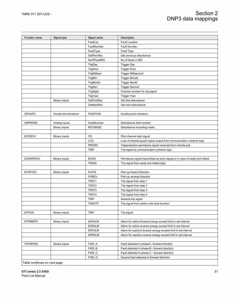
Function name Signal type Signal name Description FaultLoc Fault Location FaultNumber Fault Number FaultType Fault Type GetPrevRec Get previous disturbance NoOfFaultIED No of faults in IED TrigDay Trigger Day TrigHour Trigger Hour TrigMillisec Trigger Millisecond TrigMin Trigger Minute TrigMonth Trigger Month TrigSec Trigger Second TrigSigId Channel number for trig signal TrigYear Trigger Year Binary inputs GetFirstRec Get first disturbance GetNextRec Get next disturbance DPGAPC Double bit indications POSITION Double point indication DRPRDRE Analog inputs FaultNumber Disturbance fault number Binary inputs RECMADE Disturbance recording made ECPSCH Binary inputs CS Pilot channel start signal LCG Loss of channel guard signal output from communication scheme logic PRORX Teleprotection permissive signal received from remote end TRIP Trip signal by communication scheme logic ECRWPSCH Binary inputs ECHO Permissive signal transmitted as echo signal or in case of weak end infeed TRWEI Trip signal from weak end infeed logic EF4PTOC Binary inputs PUFW Pick up foward direction PUREV Pick up reverse direction TRST1 Trip signal from step 1 TRST2 Trip signal from step 2 TRST3 Trip signal from step 3 TRST4 Trip signal from step 4 TRIP General trip signal TRSOTF Trip signal from switch onto fault function EFPIOC Binary inputs TRIP Trip signal ETPMMTR Binary inputs EAFALM Alarm for active forward energy exceed limit in set interval EARALM Alarm for active reverse energy exceed limit in set interval ERFALM Alarm for reactive forward energy exceed limit in set interval ERRALM Alarm for reactive reverse energy exceed limit in set interval FDPSPDIS Binary inputs FWD_A Fault detected in phaseA - forward direction FWD_B Fault detected in phase B - forward direction FWD_C Fault detected in phase C - forward direction FWD_G Ground fault detected in forward direction
Table continues on next page
1MRK 511 307-UUS - Section 2DNP3 data mappings
670 series 2.0 ANSI 31Point List Manual
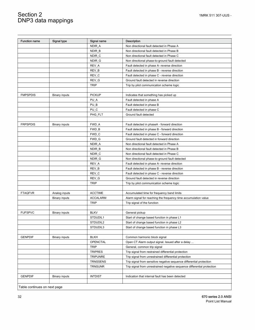
Function name Signal type Signal name Description NDIR_A Non directional fault detected in Phase A NDIR_B Non directional fault detected in Phase B NDIR_C Non directional fault detected in Phase C NDIR_G Non directional phase-to-ground fault detected REV_A Fault detected in phase A- reverse direction REV_B Fault detected in phase B - reverse direction REV_C Fault detected in phase C - reverse direction REV_G Ground fault detected in reverse direction TRIP Trip by pilot communication scheme logic FMPSPDIS Binary inputs PICKUP Indicates that something has picked up PU_A Fault detected in phase A PU_B Fault detected in phase B PU_C Fault detected in phase C PHG_FLT Ground fault detected FRPSPDIS Binary inputs FWD_A Fault detected in phaseA - forward direction FWD_B Fault detected in phase B - forward direction FWD_C Fault detected in phase C - forward direction FWD_G Ground fault detected in forward direction NDIR_A Non directional fault detected in Phase A NDIR_B Non directional fault detected in Phase B NDIR_C Non directional fault detected in Phase C NDIR_G Non directional phase-to-ground fault detected REV_A Fault detected in phase A- reverse direction REV_B Fault detected in phase B - reverse direction REV_C Fault detected in phase C - reverse direction REV_G Ground fault detected in reverse direction TRIP Trip by pilot communication scheme logic FTAQFVR Analog inputs ACCTIME Accumulated time for frequency band limits Binary inputs ACCALARM Alarm signal for reaching the frequency time accumulation value TRIP Trip signal of the function FUFSPVC Binary inputs BLKV General pickup STDUDIL1 Start of change based function in phase L1 STDUDIL2 Start of change based function in phase L2 STDUDIL3 Start of change based function in phase L3 GENPDIF Binary inputs BLKH Common harmonic block signal OPENCTAL Open CT Alarm output signal. Issued after a delay ... TRIP General, common trip signal TRIPRES Trip signal from restrained differential protection TRIPUNRE Trip signal from unrestrained differential protection TRNSSENS Trip signal from sensitive negative sequence differential protection TRNSUNR Trip signal from unrestrained negative sequence differential protection GENPDIF Binary inputs INTDIST Indication that internal fault has been detected
Table continues on next page
Section 2 1MRK 511 307-UUS -DNP3 data mappings
32 670 series 2.0 ANSIPoint List Manual
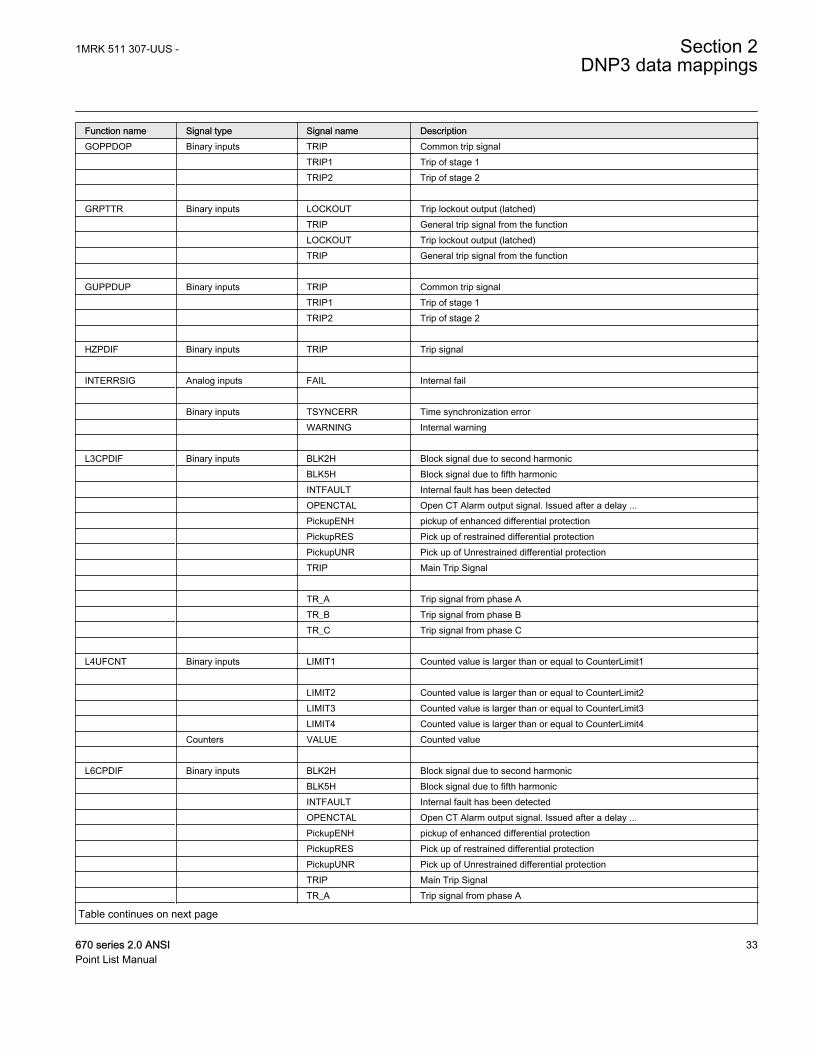
Function name Signal type Signal name DescriptionGOPPDOP Binary inputs TRIP Common trip signal TRIP1 Trip of stage 1 TRIP2 Trip of stage 2 GRPTTR Binary inputs LOCKOUT Trip lockout output (latched) TRIP General trip signal from the function LOCKOUT Trip lockout output (latched) TRIP General trip signal from the function GUPPDUP Binary inputs TRIP Common trip signal TRIP1 Trip of stage 1 TRIP2 Trip of stage 2 HZPDIF Binary inputs TRIP Trip signal INTERRSIG Analog inputs FAIL Internal fail Binary inputs TSYNCERR Time synchronization error WARNING Internal warning L3CPDIF Binary inputs BLK2H Block signal due to second harmonic BLK5H Block signal due to fifth harmonic INTFAULT Internal fault has been detected OPENCTAL Open CT Alarm output signal. Issued after a delay ... PickupENH pickup of enhanced differential protection PickupRES Pick up of restrained differential protection PickupUNR Pick up of Unrestrained differential protection TRIP Main Trip Signal TR_A Trip signal from phase A TR_B Trip signal from phase B TR_C Trip signal from phase C L4UFCNT Binary inputs LIMIT1 Counted value is larger than or equal to CounterLimit1 LIMIT2 Counted value is larger than or equal to CounterLimit2 LIMIT3 Counted value is larger than or equal to CounterLimit3 LIMIT4 Counted value is larger than or equal to CounterLimit4 Counters VALUE Counted value L6CPDIF Binary inputs BLK2H Block signal due to second harmonic BLK5H Block signal due to fifth harmonic INTFAULT Internal fault has been detected OPENCTAL Open CT Alarm output signal. Issued after a delay ... PickupENH pickup of enhanced differential protection PickupRES Pick up of restrained differential protection PickupUNR Pick up of Unrestrained differential protection TRIP Main Trip Signal TR_A Trip signal from phase A
Table continues on next page
1MRK 511 307-UUS - Section 2DNP3 data mappings
670 series 2.0 ANSI 33Point List Manual
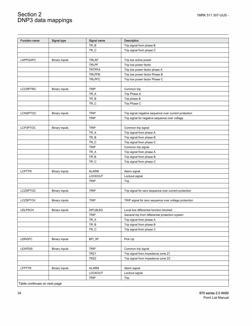
Function name Signal type Signal name Description TR_B Trip signal from phase B TR_C Trip signal from phase C LAPPGAPC Binary inputs TRLAP Trip low active power TRLPF Trip low power factor TRTPFA Trip low power factor phase A TRLPFB Trip low power factor Phase B TRLPFC Trip low power factor Phase C LCCRPTRC Binary inputs TRIP Common trip TR_A Trip Phase A TR_B Trip phase B TR_C Trip Phase C LCNSPTOC Binary inputs TRIP Trip signal negative sequence over current protection TRIP Trip signal for negative sequence over voltage LCP3PTOC Binary inputs TRIP Common trip signal TR_A Trip signal from phase A TR_B Trip signal from phase B TR_C Trip signal from phase C TRIP Common trip signal TR_A Trip signal from phase A TR_B Trip signal from phase B TR_C Trip signal from phase C LCPTTR Binary inputs ALARM Alarm signal LOCKOUT Lockout signal TRIP Trip LCZSPTOC Binary inputs TRIP Trip signal for zero sequence over current protection LCZSPTOV Binary inputs TRIP TRIP signal for zero sequence over voltage protection LDLPSCH Binary inputs DIFLBLKD Local line differential function blocked TRIP General trip from differential protection system TR_A Trip signal from phase A TR_B Trip signal from phase B TR_C Trip signal from phase C LDRGFC Binary inputs BFI_3P Pick Up LEXPDIS Binary inputs TRIP Common trip signal TRZ1 Trip signal from impedance zone Z1 TRZ2 Trip signal from impedance zone Z2 LFPTTR Binary inputs ALARM Alarm signal LOCKOUT Lockout signal TRIP Trip
Table continues on next page
Section 2 1MRK 511 307-UUS -DNP3 data mappings
34 670 series 2.0 ANSIPoint List Manual
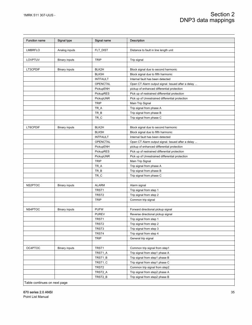
Function name Signal type Signal name Description LMBRFLO Analog inputs FLT_DIST Distance to fault in line length unit LOVPTUV Binary inputs TRIP Trip signal LT3CPDIF Binary inputs BLK2H Block signal due to second harmonic BLK5H Block signal due to fifth harmonic INTFAULT Internal fault has been detected OPENCTAL Open CT Alarm output signal. Issued after a delay ... PickupENH pickup of enhanced differential protection PickupRES Pick up of restrained differential protection PickupUNR Pick up of Unrestrained differential protection TRIP Main Trip Signal TR_A Trip signal from phase A TR_B Trip signal from phase B TR_C Trip signal from phase C LT6CPDIF Binary inputs BLK2H Block signal due to second harmonic BLK5H Block signal due to fifth harmonic INTFAULT Internal fault has been detected OPENCTAL Open CT Alarm output signal. Issued after a delay ... PickupENH pickup of enhanced differential protection PickupRES Pick up of restrained differential protection PickupUNR Pick up of Unrestrained differential protection TRIP Main Trip Signal TR_A Trip signal from phase A TR_B Trip signal from phase B TR_C Trip signal from phase C NS2PTOC Binary inputs ALARM Alarm signal TRST1 Trip signal from step 1 TRST2 Trip signal from step 2 TRIP Common trip signal NS4PTOC Binary inputs PUFW Forward directional pickup signal PUREV Reverse directional pickup signal TRST1 Trip signal from step 1 TRST2 Trip signal from step 2 TRST3 Trip signal from step 3 TRST4 Trip signal from step 4 TRIP General trip signal OC4PTOC Binary inputs TRST1 Common trip signal from step1 TRST1_A Trip signal from step1 phase A TRST1_B Trip signal from step1 phase B TRST1_C Trip signal from step1 phase C TRST2 Common trip signal from step2 TRST2_A Trip signal from step2 phase A TRST2_B Trip signal from step2 phase B
Table continues on next page
1MRK 511 307-UUS - Section 2DNP3 data mappings
670 series 2.0 ANSI 35Point List Manual
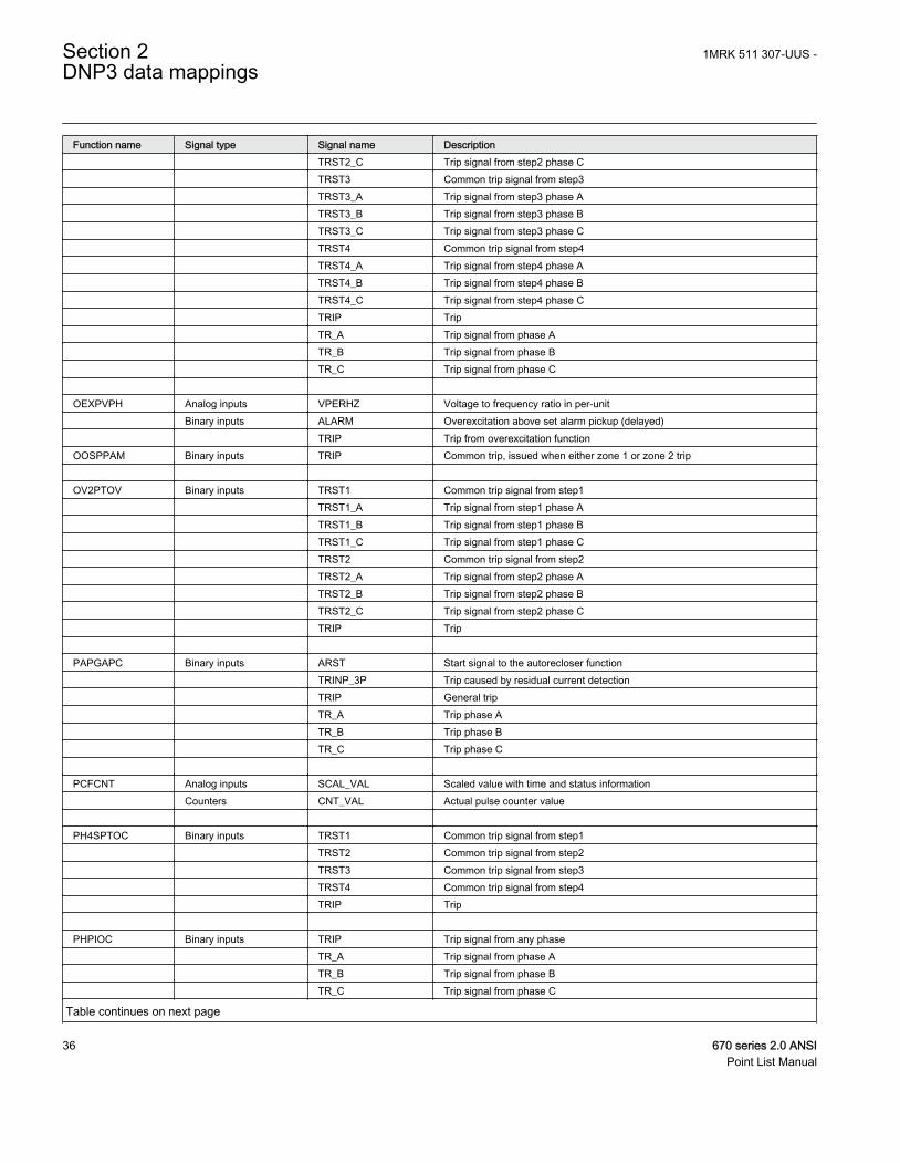
Function name Signal type Signal name Description TRST2_C Trip signal from step2 phase C TRST3 Common trip signal from step3 TRST3_A Trip signal from step3 phase A TRST3_B Trip signal from step3 phase B TRST3_C Trip signal from step3 phase C TRST4 Common trip signal from step4 TRST4_A Trip signal from step4 phase A TRST4_B Trip signal from step4 phase B TRST4_C Trip signal from step4 phase C TRIP Trip TR_A Trip signal from phase A TR_B Trip signal from phase B TR_C Trip signal from phase C OEXPVPH Analog inputs VPERHZ Voltage to frequency ratio in per-unit Binary inputs ALARM Overexcitation above set alarm pickup (delayed) TRIP Trip from overexcitation functionOOSPPAM Binary inputs TRIP Common trip, issued when either zone 1 or zone 2 trip OV2PTOV Binary inputs TRST1 Common trip signal from step1 TRST1_A Trip signal from step1 phase A TRST1_B Trip signal from step1 phase B TRST1_C Trip signal from step1 phase C TRST2 Common trip signal from step2 TRST2_A Trip signal from step2 phase A TRST2_B Trip signal from step2 phase B TRST2_C Trip signal from step2 phase C TRIP Trip PAPGAPC Binary inputs ARST Start signal to the autorecloser function TRINP_3P Trip caused by residual current detection TRIP General trip TR_A Trip phase A TR_B Trip phase B TR_C Trip phase C PCFCNT Analog inputs SCAL_VAL Scaled value with time and status information Counters CNT_VAL Actual pulse counter value PH4SPTOC Binary inputs TRST1 Common trip signal from step1 TRST2 Common trip signal from step2 TRST3 Common trip signal from step3 TRST4 Common trip signal from step4 TRIP Trip PHPIOC Binary inputs TRIP Trip signal from any phase TR_A Trip signal from phase A TR_B Trip signal from phase B TR_C Trip signal from phase C
Table continues on next page
Section 2 1MRK 511 307-UUS -DNP3 data mappings
36 670 series 2.0 ANSIPoint List Manual
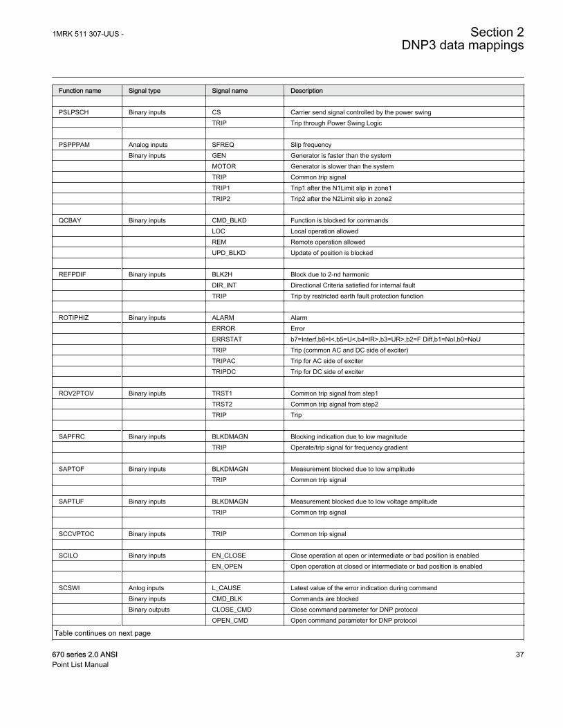
Function name Signal type Signal name Description PSLPSCH Binary inputs CS Carrier send signal controlled by the power swing TRIP Trip through Power Swing Logic PSPPPAM Analog inputs SFREQ Slip frequency Binary inputs GEN Generator is faster than the system MOTOR Generator is slower than the system TRIP Common trip signal TRIP1 Trip1 after the N1Limit slip in zone1 TRIP2 Trip2 after the N2Limit slip in zone2 QCBAY Binary inputs CMD_BLKD Function is blocked for commands LOC Local operation allowed REM Remote operation allowed UPD_BLKD Update of position is blocked REFPDIF Binary inputs BLK2H Block due to 2-nd harmonic DIR_INT Directional Criteria satisfied for internal fault TRIP Trip by restricted earth fault protection function ROTIPHIZ Binary inputs ALARM Alarm ERROR Error ERRSTAT b7=Interf,b6=I<,b5=U<,b4=IR>,b3=UR>,b2=F Diff,b1=NoI,b0=NoU TRIP Trip (common AC and DC side of exciter) TRIPAC Trip for AC side of exciter TRIPDC Trip for DC side of exciter ROV2PTOV Binary inputs TRST1 Common trip signal from step1 TRST2 Common trip signal from step2 TRIP Trip SAPFRC Binary inputs BLKDMAGN Blocking indication due to low magnitude TRIP Operate/trip signal for frequency gradient SAPTOF Binary inputs BLKDMAGN Measurement blocked due to low amplitude TRIP Common trip signal SAPTUF Binary inputs BLKDMAGN Measurement blocked due to low voltage amplitude TRIP Common trip signal SCCVPTOC Binary inputs TRIP Common trip signal SCILO Binary inputs EN_CLOSE Close operation at open or intermediate or bad position is enabled EN_OPEN Open operation at closed or intermediate or bad position is enabled SCSWI Anlog inputs L_CAUSE Latest value of the error indication during command Binary inputs CMD_BLK Commands are blocked Binary outputs CLOSE_CMD Close command parameter for DNP protocol OPEN_CMD Open command parameter for DNP protocol
Table continues on next page
1MRK 511 307-UUS - Section 2DNP3 data mappings
670 series 2.0 ANSI 37Point List Manual
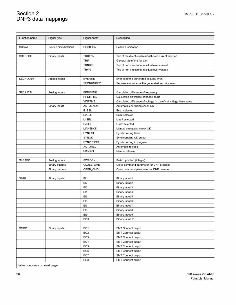
Function name Signal type Signal name Description SCSWI Double bit indications POSITION Position indication SDEPSDE Binary inputs TRDIRIN Trip of the directional residual over current function TRIP General trip of the function TRNDIN Trip of non directional residual over current TRVN Trip of non directional residual over voltage SECALARM Analog inputs EVENTID EventId of the generated security event SEQNUMBER Sequence number of the generated security event SESRSYN Analog inputs FRDIFFME Calculated difference of frequency PHDIFFME Calculated difference of phase angle VDIFFME Calculated difference of voltage in p.u of set voltage base value Binary inputs AUTOENOK Automatic energizing check OK B1SEL Bus1 selected B2SEL Bus2 selected L1SEL Line1 selected L2SEL Line2 selected MANENOK Manual energizing check OK SYNFAIL Synchronizing failed SYNOK Synchronizing OK output SYNPROGR Synchronizing in progress AUTOREL Automatic release MANREL Manual release SLGAPC Analog inputs SWPOSN Switch position (integer) Binary outputs CLOSE_CMD Close command parameter for DNP protocol Binary outputs OPEN_CMD Open command parameter for DNP protocol SMBI Binary inputs BI1 Binary input 1 BI2 Binary input 2 BI3 Binary input 3 BI4 Binary input 4 BI5 Binary input 5 BI6 Binary input 6 BI7 Binary input 7 BI8 Binary input 8 BI9 Binary input 9 BI10 Binary input 10 SMBO Binary inputs BO1 SMT Connect output BO2 SMT Connect output BO3 SMT Connect output BO4 SMT Connect output BO5 SMT Connect output BO6 SMT Connect output BO7 SMT Connect output BO8 SMT Connect output
Table continues on next page
Section 2 1MRK 511 307-UUS -DNP3 data mappings
38 670 series 2.0 ANSIPoint List Manual
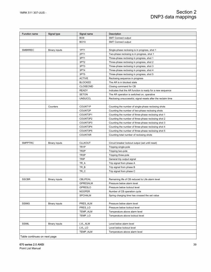
Function name Signal type Signal name Description BO9 SMT Connect output BO10 SMT Connect output SMBRREC Binary inputs 1PT1 Single-phase reclosing is in progress, shot 1 2PT1 Two-phase reclosing is in progress, shot 1 3PT1 Three-phase reclosing in progress, shot 1 3PT2 Three-phase reclosing in progress, shot 2 3PT3 Three-phase reclosing in progress, shot 3 3PT4 Three-phase reclosing in progress, shot 4 3PT5 Three-phase reclosing in progress, shot 5 ACTIVE Reclosing sequence in progress BLOCKED The AR is in blocked state CLOSECMD Closing command for CB READY Indicates that the AR function is ready for a new sequence SETON The AR operation is switched on, operative UNSUCCL Reclosing unsuccessful, signal resets after the reclaim time Counters COUNT1P Counting the number of single-phase reclosing shots COUNT2P Counting the number of two-phase reclosing shots COUNT3P1 Counting the number of three-phase reclosing shot 1 COUNT3P2 Counting the number of three-phase reclosing shot 2 COUNT3P3 Counting the number of three-phase reclosing shot 3 COUNT3P4 Counting the number of three-phase reclosing shot 4 COUNT3P5 Counting the number of three-phase reclosing shot 5 COUNTAR Counting total number of reclosing shots SMPPTRC Binary inputs CLLKOUT Circuit breaker lockout output (set until reset) TR1P Tripping single-pole TR2P Tripping two-pole TR3P Tripping three-pole TRIP General trip output signal TR_A Trip signal from phase A TR_B Trip signal from phase B TR_C Trip signal from phase C SSCBR Binary inputs CBLIFEAL Remaining life of CB reduced to Life alarm level GPRESALM Pressure below alarm level GPRESLO Pressure below lockout level NOOPER Number of CB operation cycle SPCHALM Spring charging time has crossed the set value SSIMG Binary inputs PRES_ALM Pressure below alarm level PRES_LO Pressure below lockout level TEMP_ALM Temperature above alarm level TEMP_LO Temperature above lockout level SSIML Binary inputs LVL_ALM Level below alarm level LVL_LO Level below lockout level TEMP_ALM Temperature above alarm level
Table continues on next page
1MRK 511 307-UUS - Section 2DNP3 data mappings
670 series 2.0 ANSI 39Point List Manual
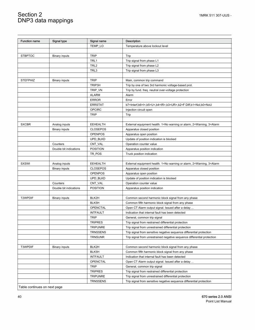
Function name Signal type Signal name Description TEMP_LO Temperature above lockout level STBPTOC Binary inputs TRIP Trip TRL1 Trip signal from phase L1 TRL2 Trip signal from phase L2 TRL3 Trip signal from phase L3 STEFPHIZ Binary inputs TRIP Main, common trip command TRIP3H Trip by one of two 3rd harmonic voltage-based prot. TRIP_VN Trip by fund. freq. neutral over-voltage protection ALARM Alarm ERROR Error ERRSTAT b7=Interf,b6=I<,b5=U<,b4=IR>,b3=UR>,b2=F Diff,b1=NoI,b0=NoU OPCIRC Injection circuit open TRIP Trip SXCBR Analog inputs EEHEALTH External equipment health. 1=No warning or alarm, 2=Warning, 3=Alarm Binary inputs CLOSEPOS Apparatus closed position OPENPOS Apparatus open position UPD_BLKD Update of position indication is blocked Counters CNT_VAL Operation counter value Double bit indications POSITION Apparatus position indication TR_POS Truck position indication SXSWI Analog inputs EEHEALTH External equipment health. 1=No warning or alarm, 2=Warning, 3=Alarm Binary inputs CLOSEPOS Apparatus closed position OPENPOS Apparatus open position UPD_BLKD Update of position indication is blocked Counters CNT_VAL Operation counter value Double bit indications POSITION Apparatus position indication T2WPDIF Binary inputs BLK2H Common second harmonic block signal from any phase BLK5H Common fifth harmonic block signal from any phase OPENCTAL Open CT Alarm output signal. Issued after a delay ... INTFAULT Indication that internal fault has been detected TRIP General, common trip signal TRIPRES Trip signal from restrained differential protection TRIPUNRE Trip signal from unrestrained differential protection TRNSSENS Trip signal from sensitive negative sequence differential protection TRNSUNR Trip signal from unrestrained negative sequence differential protection T3WPDIF Binary inputs BLK2H Common second harmonic block signal from any phase BLK5H Common fifth harmonic block signal from any phase INTFAULT Indication that internal fault has been detected OPENCTAL Open CT Alarm output signal. Issued after a delay ... TRIP General, common trip signal TRIPRES Trip signal from restrained differential protection TRIPUNRE Trip signal from unrestrained differential protection TRNSSENS Trip signal from sensitive negative sequence differential protection
Table continues on next page
Section 2 1MRK 511 307-UUS -DNP3 data mappings
40 670 series 2.0 ANSIPoint List Manual
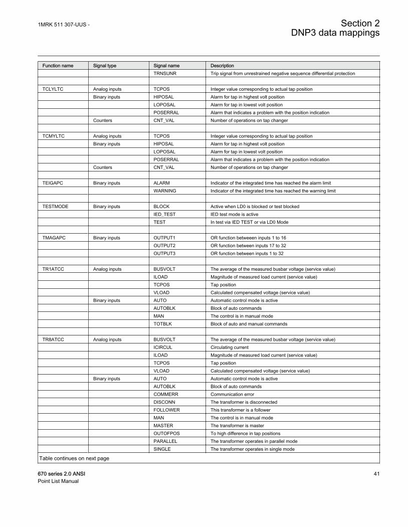
Function name Signal type Signal name Description TRNSUNR Trip signal from unrestrained negative sequence differential protection TCLYLTC Analog inputs TCPOS Integer value corresponding to actual tap position Binary inputs HIPOSAL Alarm for tap in highest volt position LOPOSAL Alarm for tap in lowest volt position POSERRAL Alarm that indicates a problem with the position indication Counters CNT_VAL Number of operations on tap changer TCMYLTC Analog inputs TCPOS Integer value corresponding to actual tap position Binary inputs HIPOSAL Alarm for tap in highest volt position LOPOSAL Alarm for tap in lowest volt position POSERRAL Alarm that indicates a problem with the position indication Counters CNT_VAL Number of operations on tap changer TEIGAPC Binary inputs ALARM Indicator of the integrated time has reached the alarm limit WARNING Indicator of the integrated time has reached the warning limit TESTMODE Binary inputs BLOCK Active when LD0 is blocked or test blocked IED_TEST IED test mode is active TEST In test via IED TEST or via LD0 Mode TMAGAPC Binary inputs OUTPUT1 OR function betweeen inputs 1 to 16 OUTPUT2 OR function between inputs 17 to 32 OUTPUT3 OR function between inputs 1 to 32 TR1ATCC Analog inputs BUSVOLT The average of the measured busbar voltage (service value) ILOAD Magnitude of measured load current (service value) TCPOS Tap position VLOAD Calculated compensated voltage (service value) Binary inputs AUTO Automatic control mode is active AUTOBLK Block of auto commands MAN The control is in manual mode TOTBLK Block of auto and manual commands TR8ATCC Analog inputs BUSVOLT The average of the measured busbar voltage (service value) ICIRCUL Circulating current ILOAD Magnitude of measured load current (service value) TCPOS Tap position VLOAD Calculated compensated voltage (service value) Binary inputs AUTO Automatic control mode is active AUTOBLK Block of auto commands COMMERR Communication error DISCONN The transformer is disconnected FOLLOWER This transformer is a follower MAN The control is in manual mode MASTER The transformer is master OUTOFPOS To high difference in tap positions PARALLEL The transformer operates in parallel mode SINGLE The transformer operates in single mode
Table continues on next page
1MRK 511 307-UUS - Section 2DNP3 data mappings
670 series 2.0 ANSI 41Point List Manual
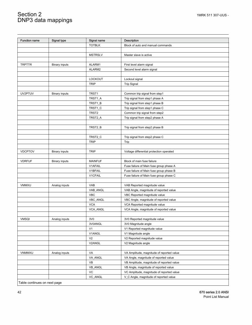
Function name Signal type Signal name Description TOTBLK Block of auto and manual commands MSTRSLV Master slave is active TRPTTR Binary inputs ALARM1 First level alarm signal ALARM2 Second level alarm signal LOCKOUT Lockout signal TRIP Trip Signal UV2PTUV Binary inputs TRST1 Common trip signal from step1 TRST1_A Trip signal from step1 phase A TRST1_B Trip signal from step1 phase B TRST1_C Trip signal from step1 phase C TRST2 Common trip signal from step2 TRST2_A Trip signal from step2 phase A TRST2_B Trip signal from step2 phase B TRST2_C Trip signal from step2 phase C TRIP Trip VDCPTOV Binary inputs TRIP Voltage differential protection operated VDRFUF Binary inputs MAINFUF Block of main fuse failure V1AFAIL Fuse failure of Main fuse group phase A V1BFAIL Fuse failure of Main fuse group phase B V1CFAIL Fuse failure of Main fuse group phase C VMMXU Analog inputs VAB VAB Reported magnitude value VAB_ANGL VAB Angle, magnitude of reported value VBC VBC Reported magnitude value VBC_ANGL VBC Angle, magnitude of reported value VCA VCA Reported magnitude value VCA_ANGL VCA Angle, magnitude of reported value VMSQI Analog inputs 3V0 3V0 Reported magnitude value 3V0ANGL 3V0 Magnitude angle V1 V1 Reported magnitude value V1ANGL V1 Magnitude angle V2 V2 Reported magnitude value V2ANGL V2 Magnitude angle VNMMXU Analog inputs VA VA Amplitude, magnitude of reported value VA_ANGL VA Angle, magnitude of reported value VB VB Amplitude, magnitude of reported value VB_ANGL VB Angle, magnitude of reported value VC VC Amplitude, magnitude of reported value VC_ANGL V_C Angle, magnitude of reported value
Table continues on next page
Section 2 1MRK 511 307-UUS -DNP3 data mappings
42 670 series 2.0 ANSIPoint List Manual
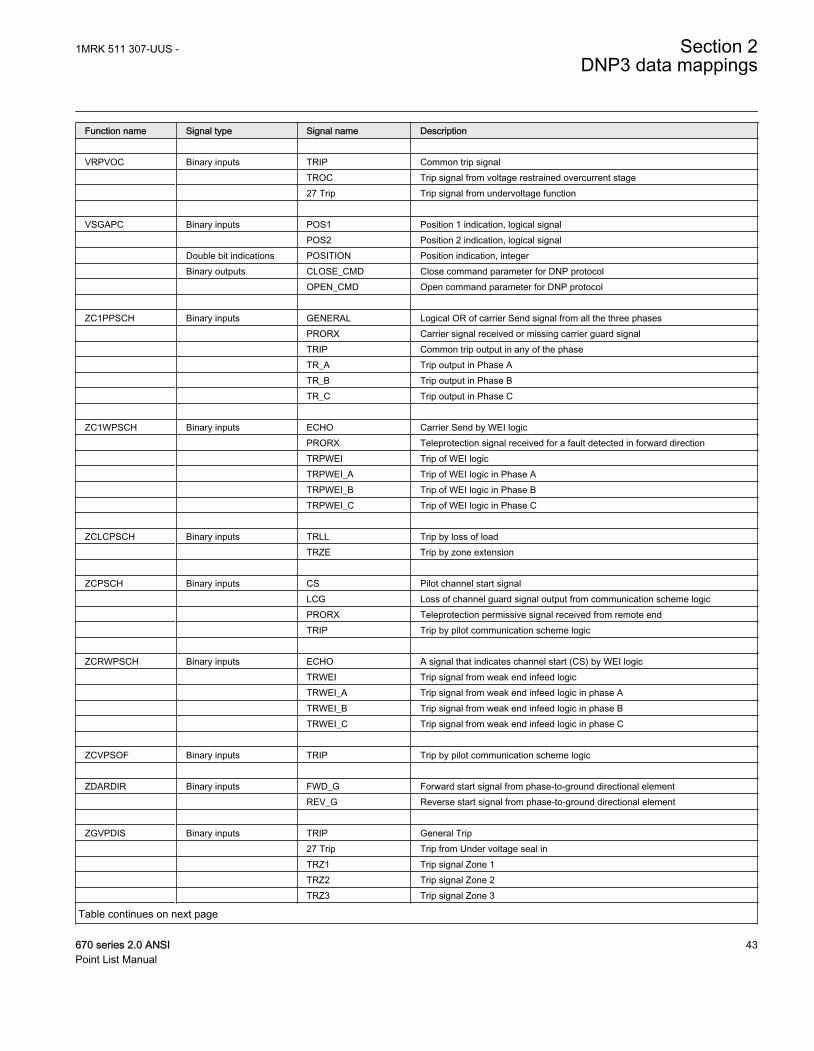
Function name Signal type Signal name Description VRPVOC Binary inputs TRIP Common trip signal TROC Trip signal from voltage restrained overcurrent stage 27 Trip Trip signal from undervoltage function VSGAPC Binary inputs POS1 Position 1 indication, logical signal POS2 Position 2 indication, logical signal Double bit indications POSITION Position indication, integer Binary outputs CLOSE_CMD Close command parameter for DNP protocol OPEN_CMD Open command parameter for DNP protocol ZC1PPSCH Binary inputs GENERAL Logical OR of carrier Send signal from all the three phases PRORX Carrier signal received or missing carrier guard signal TRIP Common trip output in any of the phase TR_A Trip output in Phase A TR_B Trip output in Phase B TR_C Trip output in Phase C ZC1WPSCH Binary inputs ECHO Carrier Send by WEI logic PRORX Teleprotection signal received for a fault detected in forward direction TRPWEI Trip of WEI logic TRPWEI_A Trip of WEI logic in Phase A TRPWEI_B Trip of WEI logic in Phase B TRPWEI_C Trip of WEI logic in Phase C ZCLCPSCH Binary inputs TRLL Trip by loss of load TRZE Trip by zone extension ZCPSCH Binary inputs CS Pilot channel start signal LCG Loss of channel guard signal output from communication scheme logic PRORX Teleprotection permissive signal received from remote end TRIP Trip by pilot communication scheme logic ZCRWPSCH Binary inputs ECHO A signal that indicates channel start (CS) by WEI logic TRWEI Trip signal from weak end infeed logic TRWEI_A Trip signal from weak end infeed logic in phase A TRWEI_B Trip signal from weak end infeed logic in phase B TRWEI_C Trip signal from weak end infeed logic in phase C ZCVPSOF Binary inputs TRIP Trip by pilot communication scheme logic ZDARDIR Binary inputs FWD_G Forward start signal from phase-to-ground directional element REV_G Reverse start signal from phase-to-ground directional element ZGVPDIS Binary inputs TRIP General Trip 27 Trip Trip from Under voltage seal in TRZ1 Trip signal Zone 1 TRZ2 Trip signal Zone 2 TRZ3 Trip signal Zone 3
Table continues on next page
1MRK 511 307-UUS - Section 2DNP3 data mappings
670 series 2.0 ANSI 43Point List Manual
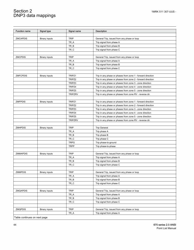
Function name Signal type Signal name Description ZMCAPDIS Binary inputs TRIP General Trip, issued from any phase or loop TR_A Trip signal from phase A TR_B Trip signal from phase B TR_C Trip signal from phase C ZMCPDIS Binary inputs TRIP General Trip, issued from any phase or loop TR_A Trip signal from phase A TR_B Trip signal from phase B TR_C Trip signal from phase C ZMFCPDIS Binary inputs TRIPZ1 Trip in any phase or phases from zone 1 - forward direction TRIPZ2 Trip in any phase or phases from zone 2 - forward direction TRIPZ3 Trip in any phase or phases from zone 3 - zone direction TRIPZ4 Trip in any phase or phases from zone 4 - zone direction TRIPZ5 Trip in any phase or phases from zone 5 - zone direction TRIPZRV Trip in any phase or phases from zone RV - reverse dir. ZMFPDIS Binary inputs TRIPZ1 Trip in any phase or phases from zone 1 - forward direction TRIPZ2 Trip in any phase or phases from zone 2 - forward direction TRIPZ3 Trip in any phase or phases from zone 3 - zone direction TRIPZ4 Trip in any phase or phases from zone 4 - zone direction TRIPZ5 Trip in any phase or phases from zone 5 - zone direction TRIPZRV Trip in any phase or phases from zone RV - reverse dir. ZMHPDIS Binary inputs TRIP Trip General TR_A Trip phase A TR_B Trip phase B TR_C Trip phase C TRPG Trip phase-to-ground TRPP Trip phase-to-phase ZMMAPDIS Binary inputs TRIP General Trip, issued from any phase or loop TR_A Trip signal from phase A TR_B Trip signal from phase B TR_C Trip signal from phase C ZMMPDIS Binary inputs TRIP General Trip, issued from any phase or loop TR_A Trip signal from phase A TR_B Trip signal from phase B TR_C Trip signal from phase C ZMQAPDIS Binary inputs TRIP General Trip, issued from any phase or loop TR_A Trip signal from phase A TR_B Trip signal from phase B TR_C Trip signal from phase C ZMQPDIS Binary inputs TRIP General Trip, issued from any phase or loop TR_A Trip signal from phase A
Table continues on next page
Section 2 1MRK 511 307-UUS -DNP3 data mappings
44 670 series 2.0 ANSIPoint List Manual
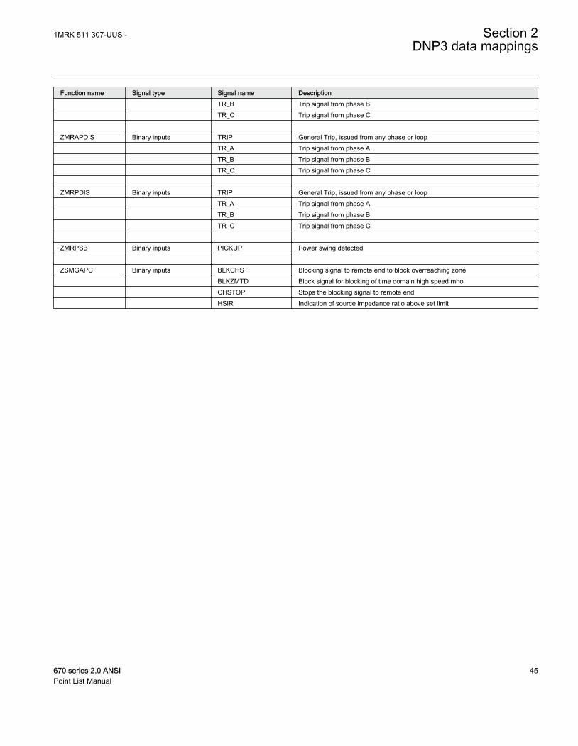
Function name Signal type Signal name Description TR_B Trip signal from phase B TR_C Trip signal from phase C ZMRAPDIS Binary inputs TRIP General Trip, issued from any phase or loop TR_A Trip signal from phase A TR_B Trip signal from phase B TR_C Trip signal from phase C ZMRPDIS Binary inputs TRIP General Trip, issued from any phase or loop TR_A Trip signal from phase A TR_B Trip signal from phase B TR_C Trip signal from phase C ZMRPSB Binary inputs PICKUP Power swing detected ZSMGAPC Binary inputs BLKCHST Blocking signal to remote end to block overreaching zone BLKZMTD Block signal for blocking of time domain high speed mho CHSTOP Stops the blocking signal to remote end HSIR Indication of source impedance ratio above set limit
1MRK 511 307-UUS - Section 2DNP3 data mappings
670 series 2.0 ANSI 45Point List Manual

46
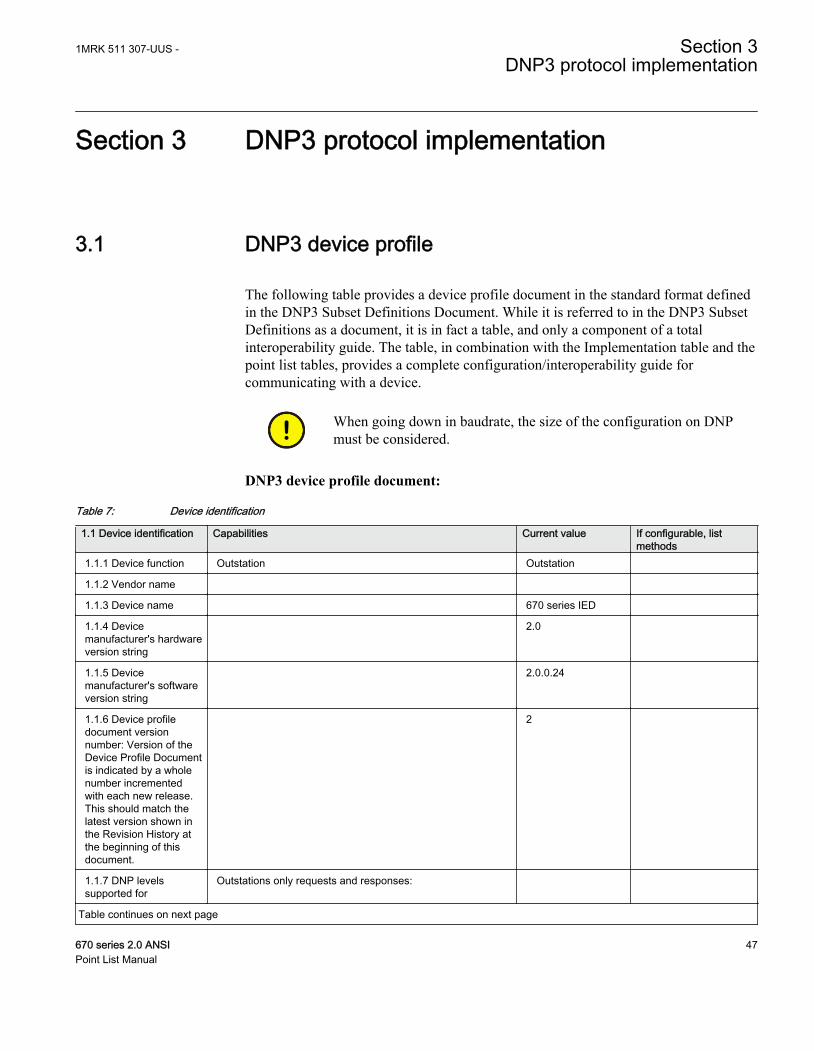
Section 3 DNP3 protocol implementation
3.1 DNP3 device profile
The following table provides a device profile document in the standard format definedin the DNP3 Subset Definitions Document. While it is referred to in the DNP3 SubsetDefinitions as a document, it is in fact a table, and only a component of a totalinteroperability guide. The table, in combination with the Implementation table and thepoint list tables, provides a complete configuration/interoperability guide forcommunicating with a device.
When going down in baudrate, the size of the configuration on DNPmust be considered.
DNP3 device profile document:
Table 7: Device identification
1.1 Device identification Capabilities Current value If configurable, listmethods
1.1.1 Device function Outstation Outstation
1.1.2 Vendor name
1.1.3 Device name 670 series IED
1.1.4 Devicemanufacturer's hardwareversion string
2.0
1.1.5 Devicemanufacturer's softwareversion string
2.0.0.24
1.1.6 Device profiledocument versionnumber: Version of theDevice Profile Documentis indicated by a wholenumber incrementedwith each new release.This should match thelatest version shown inthe Revision History atthe beginning of thisdocument.
2
1.1.7 DNP levelssupported for
Outstations only requests and responses:
Table continues on next page
1MRK 511 307-UUS - Section 3DNP3 protocol implementation
670 series 2.0 ANSI 47Point List Manual
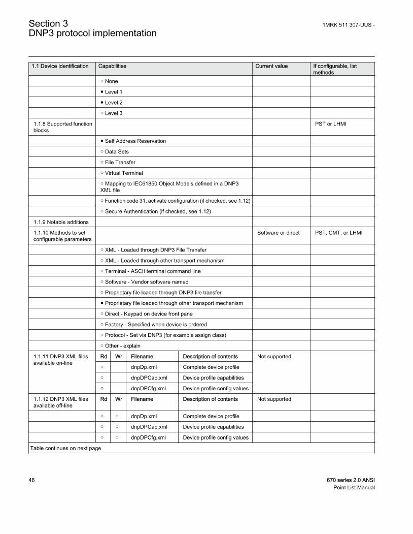
1.1 Device identification Capabilities Current value If configurable, listmethods
○ None
● Level 1
● Level 2
○ Level 3
1.1.8 Supported functionblocks
PST or LHMI
● Self Address Reservation
○ Data Sets
○ File Transfer
○ Virtual Terminal
○ Mapping to IEC61850 Object Models defined in a DNP3XML file
○ Function code 31, activate configuration (if checked, see 1.12)
○ Secure Authentication (if checked, see 1.12)
1.1.9 Notable additions
1.1.10 Methods to setconfigurable parameters
Software or direct PST, CMT, or LHMI
○ XML - Loaded through DNP3 File Transfer
○ XML - Loaded through other transport mechanism
○ Terminal - ASCII terminal command line
○ Software - Vendor software named
○ Proprietary file loaded through DNP3 file transfer
● Proprietary file loaded through other transport mechanism
○ Direct - Keypad on device front pane
○ Factory - Specified when device is ordered
○ Protocol - Set via DNP3 (for example assign class)
○ Other - explain
1.1.11 DNP3 XML filesavailable on-line
Rd Wr Filename Description of contents Not supported
○ dnpDp.xml Complete device profile
○ dnpDPCap.xml Device profile capabilities
○ dnpDPCfg.xml Device profile config values
1.1.12 DNP3 XML filesavailable off-line
Rd Wr Filename Description of contents Not supported
○ ○ dnpDp.xml Complete device profile
○ ○ dnpDPCap.xml Device profile capabilities
○ ○ dnpDPCfg.xml Device profile config values
Table continues on next page
Section 3 1MRK 511 307-UUS -DNP3 protocol implementation
48 670 series 2.0 ANSIPoint List Manual
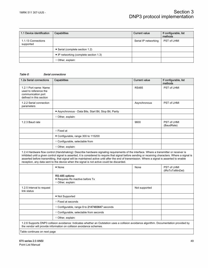
1.1 Device identification Capabilities Current value If configurable, listmethods
1.1.13 Connectionssupported
Serial IP networking PST of LHMI
● Serial (complete section 1.2)
● IP networking (complete section 1.3)
○ Other, explain:
Table 8: Serial connections
1.2a Serial connections Capabilities Current value If configurable, listmethods
1.2.1 Port name: Nameused to reference thecommunication portdefined in this section
RS485 PST of LHMI
1.2.2 Serial connectionparameters
Asynchronous PST of LHMI
● Asynchronous - Data Bits, Start Bit, Stop Bit, Parity
○ Other, explain:
1.2.3 Baud rate 9600 PST of LHMI(BaudRate)
○ Fixed at
● Configurable, range 300 to 115200
○ Configurable, selectable from
○ Other, explain:
1.2.4 Hardware flow control (Handshaking): Describe hardware signaling requirements of the interface. Where a transmitter or receiver isinhibited until a given control signal is asserted, it is considered to require that signal before sending or receiving characters. Where a signal isasserted before transmitting, that signal will be maintained active until after the end of transmission. Where a signal is asserted to enablereception, any data sent to the device when the signal is not active could be discarded.
● None None PST of LHMI(tRxToTxMinDel)
RS-485 options:● Requires Rx inactive before Tx○ Other, explain:
1.2.5 Interval to requestlink status
Not supported
● Not Supported
○ Fixed at seconds
○ Configurable, range 0 to 2147483647 seconds
○ Configurable, selectable from seconds
○ Other, explain:
1.2.6 Supports DNP3 collision avoidance: Indicates whether an Outstation uses a collision avoidance algorithm. Documentation provided bythe vendor will provide information on collision avoidance schemes.
Table continues on next page
1MRK 511 307-UUS - Section 3DNP3 protocol implementation
670 series 2.0 ANSI 49Point List Manual
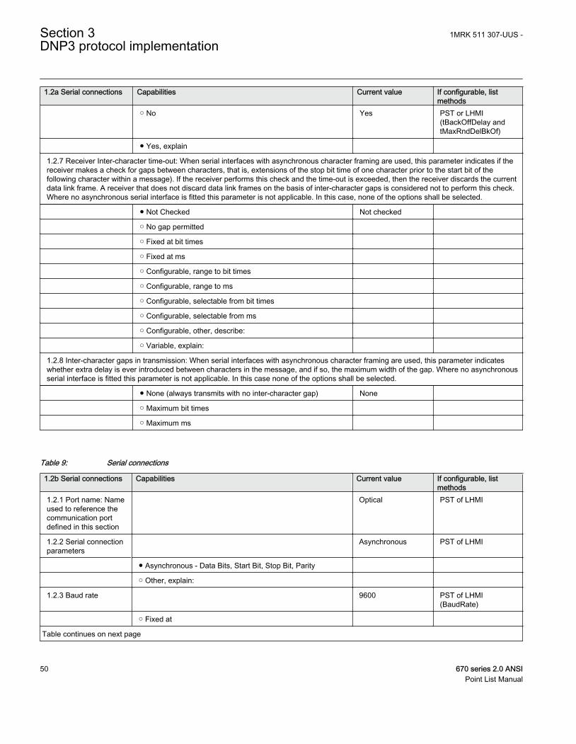
1.2a Serial connections Capabilities Current value If configurable, listmethods
○ No Yes PST or LHMI(tBackOffDelay andtMaxRndDelBkOf)
● Yes, explain
1.2.7 Receiver Inter-character time-out: When serial interfaces with asynchronous character framing are used, this parameter indicates if thereceiver makes a check for gaps between characters, that is, extensions of the stop bit time of one character prior to the start bit of thefollowing character within a message). If the receiver performs this check and the time-out is exceeded, then the receiver discards the currentdata link frame. A receiver that does not discard data link frames on the basis of inter-character gaps is considered not to perform this check.Where no asynchronous serial interface is fitted this parameter is not applicable. In this case, none of the options shall be selected.
● Not Checked Not checked
○ No gap permitted
○ Fixed at bit times
○ Fixed at ms
○ Configurable, range to bit times
○ Configurable, range to ms
○ Configurable, selectable from bit times
○ Configurable, selectable from ms
○ Configurable, other, describe:
○ Variable, explain:
1.2.8 Inter-character gaps in transmission: When serial interfaces with asynchronous character framing are used, this parameter indicateswhether extra delay is ever introduced between characters in the message, and if so, the maximum width of the gap. Where no asynchronousserial interface is fitted this parameter is not applicable. In this case none of the options shall be selected.
● None (always transmits with no inter-character gap) None
○ Maximum bit times
○ Maximum ms
Table 9: Serial connections
1.2b Serial connections Capabilities Current value If configurable, listmethods
1.2.1 Port name: Nameused to reference thecommunication portdefined in this section
Optical PST of LHMI
1.2.2 Serial connectionparameters
Asynchronous PST of LHMI
● Asynchronous - Data Bits, Start Bit, Stop Bit, Parity
○ Other, explain:
1.2.3 Baud rate 9600 PST of LHMI(BaudRate)
○ Fixed at
Table continues on next page
Section 3 1MRK 511 307-UUS -DNP3 protocol implementation
50 670 series 2.0 ANSIPoint List Manual
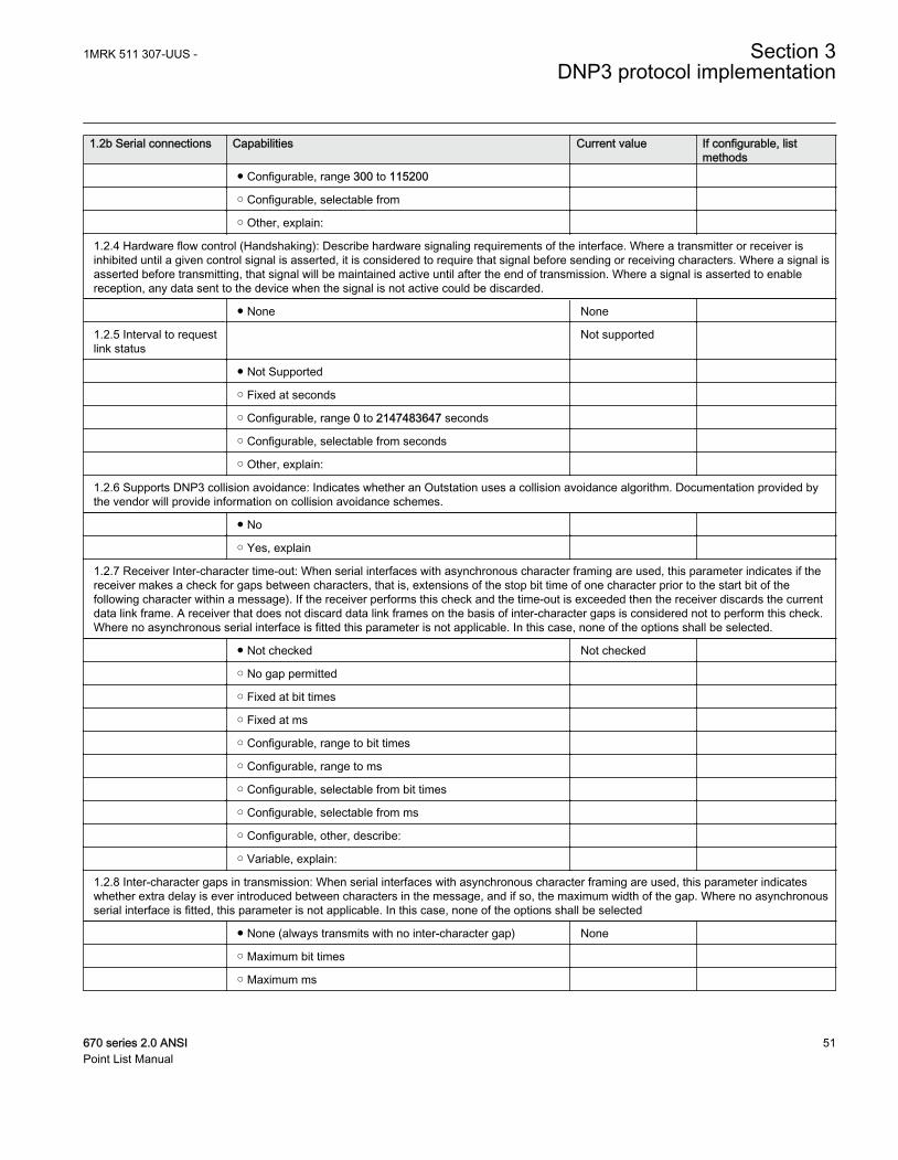
1.2b Serial connections Capabilities Current value If configurable, listmethods
● Configurable, range 300 to 115200
○ Configurable, selectable from
○ Other, explain:
1.2.4 Hardware flow control (Handshaking): Describe hardware signaling requirements of the interface. Where a transmitter or receiver isinhibited until a given control signal is asserted, it is considered to require that signal before sending or receiving characters. Where a signal isasserted before transmitting, that signal will be maintained active until after the end of transmission. Where a signal is asserted to enablereception, any data sent to the device when the signal is not active could be discarded.
● None None
1.2.5 Interval to requestlink status
Not supported
● Not Supported
○ Fixed at seconds
○ Configurable, range 0 to 2147483647 seconds
○ Configurable, selectable from seconds
○ Other, explain:
1.2.6 Supports DNP3 collision avoidance: Indicates whether an Outstation uses a collision avoidance algorithm. Documentation provided bythe vendor will provide information on collision avoidance schemes.
● No
○ Yes, explain
1.2.7 Receiver Inter-character time-out: When serial interfaces with asynchronous character framing are used, this parameter indicates if thereceiver makes a check for gaps between characters, that is, extensions of the stop bit time of one character prior to the start bit of thefollowing character within a message). If the receiver performs this check and the time-out is exceeded then the receiver discards the currentdata link frame. A receiver that does not discard data link frames on the basis of inter-character gaps is considered not to perform this check.Where no asynchronous serial interface is fitted this parameter is not applicable. In this case, none of the options shall be selected.
● Not checked Not checked
○ No gap permitted
○ Fixed at bit times
○ Fixed at ms
○ Configurable, range to bit times
○ Configurable, range to ms
○ Configurable, selectable from bit times
○ Configurable, selectable from ms
○ Configurable, other, describe:
○ Variable, explain:
1.2.8 Inter-character gaps in transmission: When serial interfaces with asynchronous character framing are used, this parameter indicateswhether extra delay is ever introduced between characters in the message, and if so, the maximum width of the gap. Where no asynchronousserial interface is fitted, this parameter is not applicable. In this case, none of the options shall be selected
● None (always transmits with no inter-character gap) None
○ Maximum bit times
○ Maximum ms
1MRK 511 307-UUS - Section 3DNP3 protocol implementation
670 series 2.0 ANSI 51Point List Manual
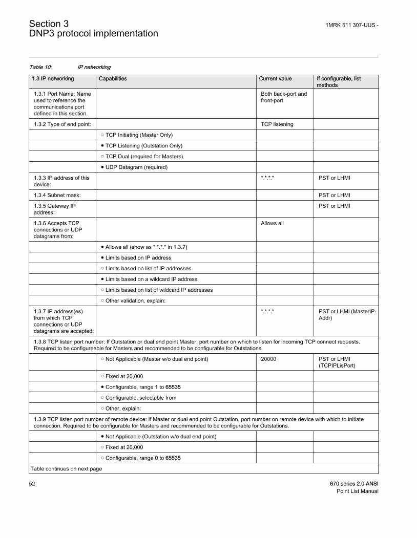
Table 10: IP networking
1.3 IP networking Capabilities Current value If configurable, listmethods
1.3.1 Port Name: Nameused to reference thecommunications portdefined in this section.
Both back-port andfront-port
1.3.2 Type of end point: TCP listening
○ TCP Initiating (Master Only)
● TCP Listening (Outstation Only)
○ TCP Dual (required for Masters)
● UDP Datagram (required)
1.3.3 IP address of thisdevice:
*.*.*.* PST or LHMI
1.3.4 Subnet mask: PST or LHMI
1.3.5 Gateway IPaddress:
PST or LHMI
1.3.6 Accepts TCPconnections or UDPdatagrams from:
Allows all
● Allows all (show as *.*.*.* in 1.3.7)
● Limits based on IP address
○ Limits based on list of IP addresses
● Limits based on a wildcard IP address
○ Limits based on list of wildcard IP addresses
○ Other validation, explain:
1.3.7 IP address(es)from which TCPconnections or UDPdatagrams are accepted:
*.*.*.* PST or LHMI (MasterIP-Addr)
1.3.8 TCP listen port number: If Outstation or dual end point Master, port number on which to listen for incoming TCP connect requests.Required to be configureable for Masters and recommended to be configurable for Outstations.
○ Not Applicable (Master w/o dual end point) 20000 PST or LHMI(TCPIPLisPort)
○ Fixed at 20,000
● Configurable, range 1 to 65535
○ Configurable, selectable from
○ Other, explain:
1.3.9 TCP listen port number of remote device: If Master or dual end point Outstation, port number on remote device with which to initiateconnection. Required to be configurable for Masters and recommended to be configurable for Outstations.
● Not Applicable (Outstation w/o dual end point)
○ Fixed at 20,000
○ Configurable, range 0 to 65535
Table continues on next page
Section 3 1MRK 511 307-UUS -DNP3 protocol implementation
52 670 series 2.0 ANSIPoint List Manual
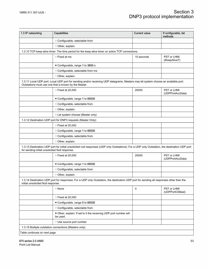
1.3 IP networking Capabilities Current value If configurable, listmethods
○ Configurable, selectable from
○ Other, explain:
1.3.10 TCP keep-alive timer: The time period for the keep-alive timer on active TCP connections.
○ Fixed at ms 10 seconds PST or LHMI(tKeepAliveT)
● Configurable, range 1 to 3600 s
○ Configurable, selectable from ms
○ Other, explain:
1.3.11 Local UDP port: Local UDP port for sending and/or receiving UDP datagrams. Masters may let system choose an available port.Outstations must use one that is known by the Master.
○ Fixed at 20,000 20000 PST or LHMI(UDPPortAccData)
● Configurable, range 1 to 65535
○ Configurable, selectable from
○ Other, explain:
○ Let system choose (Master only)
1.3.12 Destination UDP port for DNP3 requests (Master Only):
○ Fixed at 20,000
○ Configurable, range 1 to 65535
○ Configurable, selectable from
○ Other, explain:
1.3.13 Destination UDP port for initial unsolicited null responses (UDP only Outstations): For a UDP only Outstation, the destination UDP portfor sending initial unsolicited Null response.
○ Fixed at 20,000 20000 PST or LHMI(UDPPortAccData)
● Configurable, range 1 to 65535
○ Configurable, selectable from
○ Other, explain:
1.3.14 Destination UDP port for responses: For a UDP only Outstation, the destination UDP port for sending all responses other than theinitial unsolicited Null response.
○ None 0 PST or LHMI(UDPPortCliMast)
○ Fixed at 20,000
● Configurable, range 0 to 65535
○ Configurable, selectable from
● Other, explain: If set to 0 the receiving UDP port number willbe used.
○ Use source port number
1.3.15 Multiple outstation connections (Masters only):
Table continues on next page
1MRK 511 307-UUS - Section 3DNP3 protocol implementation
670 series 2.0 ANSI 53Point List Manual
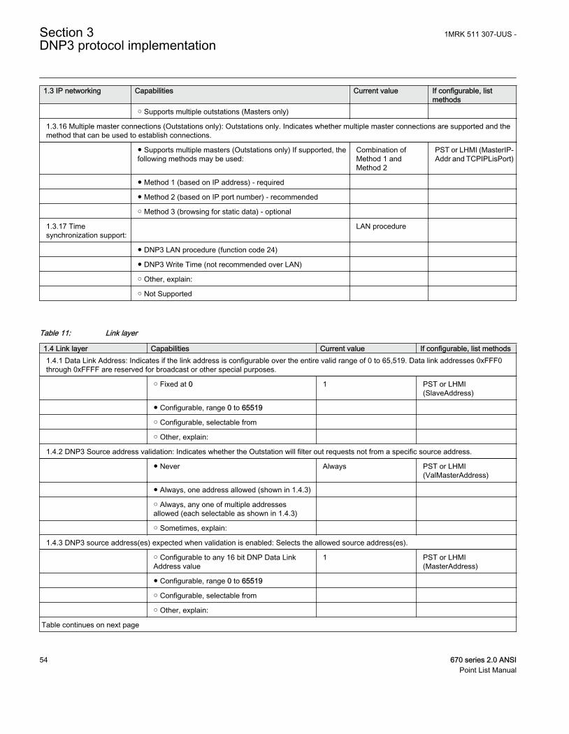
1.3 IP networking Capabilities Current value If configurable, listmethods
○ Supports multiple outstations (Masters only)
1.3.16 Multiple master connections (Outstations only): Outstations only. Indicates whether multiple master connections are supported and themethod that can be used to establish connections.
● Supports multiple masters (Outstations only) If supported, thefollowing methods may be used:
Combination ofMethod 1 andMethod 2
PST or LHMI (MasterIP-Addr and TCPIPLisPort)
● Method 1 (based on IP address) - required
● Method 2 (based on IP port number) - recommended
○ Method 3 (browsing for static data) - optional
1.3.17 Timesynchronization support:
LAN procedure
● DNP3 LAN procedure (function code 24)
● DNP3 Write Time (not recommended over LAN)
○ Other, explain:
○ Not Supported
Table 11: Link layer
1.4 Link layer Capabilities Current value If configurable, list methods1.4.1 Data Link Address: Indicates if the link address is configurable over the entire valid range of 0 to 65,519. Data link addresses 0xFFF0through 0xFFFF are reserved for broadcast or other special purposes.
○ Fixed at 0 1 PST or LHMI(SlaveAddress)
● Configurable, range 0 to 65519
○ Configurable, selectable from
○ Other, explain:
1.4.2 DNP3 Source address validation: Indicates whether the Outstation will filter out requests not from a specific source address.
● Never Always PST or LHMI(ValMasterAddress)
● Always, one address allowed (shown in 1.4.3)
○ Always, any one of multiple addressesallowed (each selectable as shown in 1.4.3)
○ Sometimes, explain:
1.4.3 DNP3 source address(es) expected when validation is enabled: Selects the allowed source address(es).
○ Configurable to any 16 bit DNP Data LinkAddress value
1 PST or LHMI(MasterAddress)
● Configurable, range 0 to 65519
○ Configurable, selectable from
○ Other, explain:
Table continues on next page
Section 3 1MRK 511 307-UUS -DNP3 protocol implementation
54 670 series 2.0 ANSIPoint List Manual
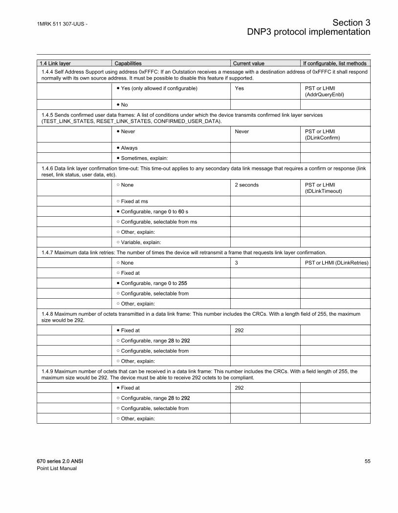
1.4 Link layer Capabilities Current value If configurable, list methods1.4.4 Self Address Support using address 0xFFFC: If an Outstation receives a message with a destination address of 0xFFFC it shall respondnormally with its own source address. It must be possible to disable this feature if supported.
● Yes (only allowed if configurable) Yes PST or LHMI(AddrQueryEnbl)
● No
1.4.5 Sends confirmed user data frames: A list of conditions under which the device transmits confirmed link layer services(TEST_LINK_STATES, RESET_LINK_STATES, CONFIRMED_USER_DATA).
● Never Never PST or LHMI(DLinkConfirm)
● Always
● Sometimes, explain:
1.4.6 Data link layer confirmation time-out: This time-out applies to any secondary data link message that requires a confirm or response (linkreset, link status, user data, etc).
○ None 2 seconds PST or LHMI(tDLinkTimeout)
○ Fixed at ms
● Configurable, range 0 to 60 s
○ Configurable, selectable from ms
○ Other, explain:
○ Variable, explain:
1.4.7 Maximum data link retries: The number of times the device will retransmit a frame that requests link layer confirmation.
○ None 3 PST or LHMI (DLinkRetries)
○ Fixed at
● Configurable, range 0 to 255
○ Configurable, selectable from
○ Other, explain:
1.4.8 Maximum number of octets transmitted in a data link frame: This number includes the CRCs. With a length field of 255, the maximumsize would be 292.
● Fixed at 292
○ Configurable, range 28 to 292
○ Configurable, selectable from
○ Other, explain:
1.4.9 Maximum number of octets that can be received in a data link frame: This number includes the CRCs. With a field length of 255, themaximum size would be 292. The device must be able to receive 292 octets to be compliant.
● Fixed at 292
○ Configurable, range 28 to 292
○ Configurable, selectable from
○ Other, explain:
1MRK 511 307-UUS - Section 3DNP3 protocol implementation
670 series 2.0 ANSI 55Point List Manual
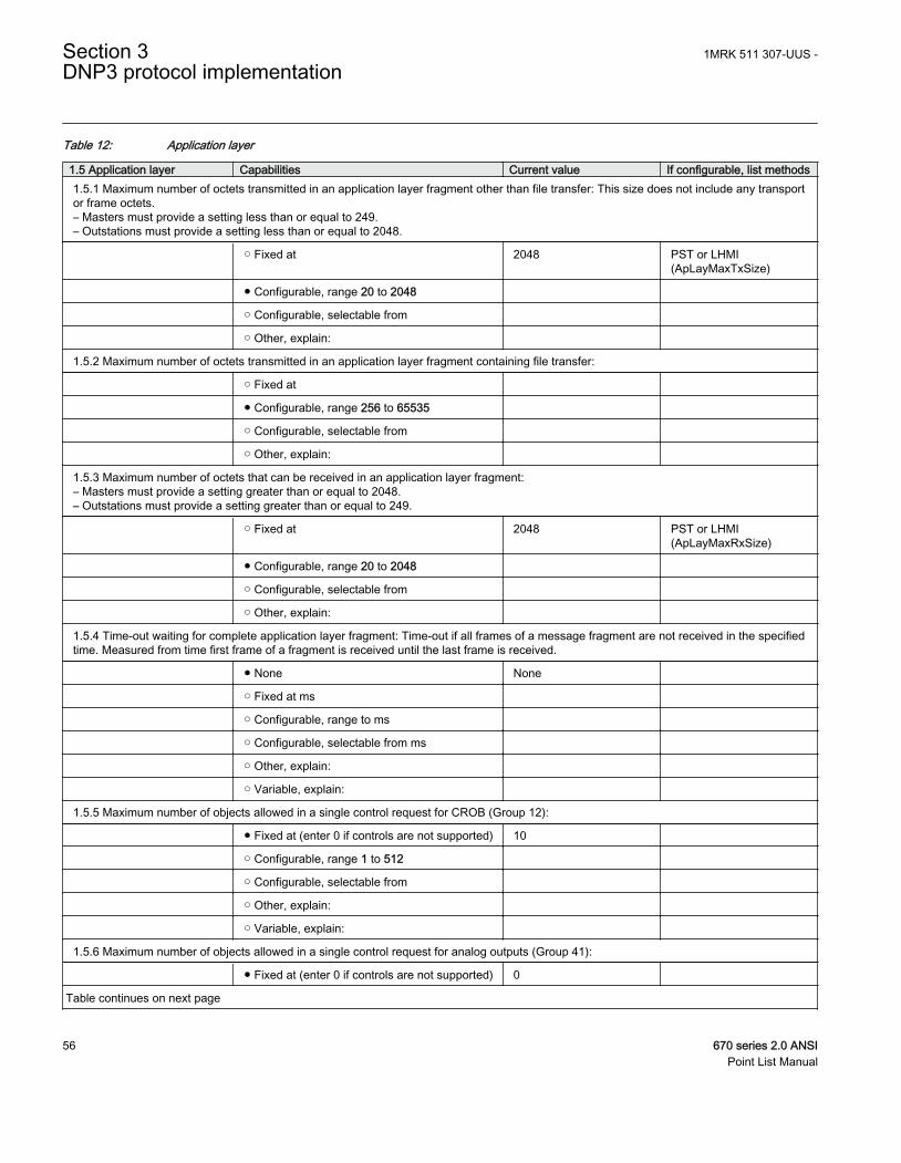
Table 12: Application layer
1.5 Application layer Capabilities Current value If configurable, list methods1.5.1 Maximum number of octets transmitted in an application layer fragment other than file transfer: This size does not include any transportor frame octets.– Masters must provide a setting less than or equal to 249.– Outstations must provide a setting less than or equal to 2048.
○ Fixed at 2048 PST or LHMI(ApLayMaxTxSize)
● Configurable, range 20 to 2048
○ Configurable, selectable from
○ Other, explain:
1.5.2 Maximum number of octets transmitted in an application layer fragment containing file transfer:
○ Fixed at
● Configurable, range 256 to 65535
○ Configurable, selectable from
○ Other, explain:
1.5.3 Maximum number of octets that can be received in an application layer fragment:– Masters must provide a setting greater than or equal to 2048.– Outstations must provide a setting greater than or equal to 249.
○ Fixed at 2048 PST or LHMI(ApLayMaxRxSize)
● Configurable, range 20 to 2048
○ Configurable, selectable from
○ Other, explain:
1.5.4 Time-out waiting for complete application layer fragment: Time-out if all frames of a message fragment are not received in the specifiedtime. Measured from time first frame of a fragment is received until the last frame is received.
● None None
○ Fixed at ms
○ Configurable, range to ms
○ Configurable, selectable from ms
○ Other, explain:
○ Variable, explain:
1.5.5 Maximum number of objects allowed in a single control request for CROB (Group 12):
● Fixed at (enter 0 if controls are not supported) 10
○ Configurable, range 1 to 512
○ Configurable, selectable from
○ Other, explain:
○ Variable, explain:
1.5.6 Maximum number of objects allowed in a single control request for analog outputs (Group 41):
● Fixed at (enter 0 if controls are not supported) 0
Table continues on next page
Section 3 1MRK 511 307-UUS -DNP3 protocol implementation
56 670 series 2.0 ANSIPoint List Manual
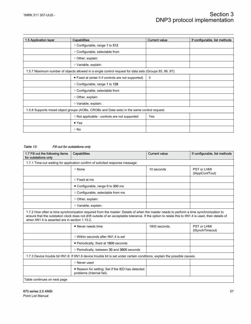
1.5 Application layer Capabilities Current value If configurable, list methods ○ Configurable, range 1 to 512
○ Configurable, selectable from
○ Other, explain:
○ Variable, explain:
1.5.7 Maximum number of objects allowed in a single control request for data sets (Groups 85, 86, 87):
● Fixed at (enter 0 if controls are not supported) 0
○ Configurable, range 1 to 128
○ Configurable, selectable from
○ Other, explain:
○ Variable, explain:
1.5.8 Supports mixed object groups (AOBs, CROBs and Data sets) in the same control request:
○ Not applicable - controls are not supported Yes
● Yes
○ No
Table 13: Fill out for outstations only
1.7 Fill out the following itemsfor outstations only
Capabilities Current value If configurable, list methods
1.7.1 Time-out waiting for application confirm of solicited response message:
○ None 10 seconds PST or LHMI(tApplConfTout)
○ Fixed at ms
● Configurable, range 0 to 300 ms
○ Configurable, selectable from ms
○ Other, explain:
○ Variable, explain:
1.7.2 How often is time synchronization required from the master: Details of when the master needs to perform a time synchronization toensure that the outstation clock does not drift outside of an acceptable tolerance. If the option to relate this to IIN1.4 is used, then details ofwhen IIN1.4 is asserted are in section 1.10.2.
● Never needs time 1800 seconds. PST or LHMI(tSynchTimeout)
○ Within seconds after IIN1.4 is set
● Periodically, fixed at 1800 seconds
○ Periodically, between 30 and 3600 seconds
1.7.3 Device trouble bit IIN1.6: If IIN1.6 device trouble bit is set under certain conditions, explain the possible causes.
○ Never used
● Reason for setting: Set if the IED has detectedproblems (Internal fail).
Table continues on next page
1MRK 511 307-UUS - Section 3DNP3 protocol implementation
670 series 2.0 ANSI 57Point List Manual
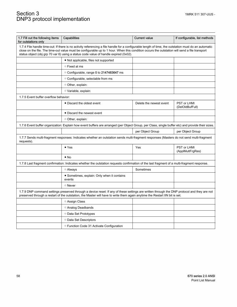
1.7 Fill out the following itemsfor outstations only
Capabilities Current value If configurable, list methods
1.7.4 File handle time-out: If there is no activity referencing a file handle for a configurable length of time, the outstation must do an automaticclose on the file. The time-out value must be configurable up to 1 hour. When this condition occurs the outstation will send a file transportstatus object (obj grp 70 var 6) using a status code value of handle expired (0x02).
● Not applicable, files not supported
○ Fixed at ms
○ Configurable, range 0 to 2147483647 ms
○ Configurable, selectable from ms
○ Other, explain:
○ Variable, explain:
1.7.5 Event buffer overflow behavior:
● Discard the oldest event Delete the newest event PST or LHMI(DelOldBufFull)
● Discard the newest event
○ Other, explain:
1.7.6 Event buffer organization: Explain how event buffers are arranged (per Object Group, per Class, single buffer etc) and provide their sizes.
per Object Group per Object Group
1.7.7 Sends multi-fragment responses: Indicates whether an outstation sends multi-fragment responses (Masters do not send multi-fragmentrequests).
● Yes Yes PST or LHMI(ApplMultFrgRes)
● No
1.7.8 Last fragment confirmation: Indicates whether the outstation requests confirmation of the last fragment of a multi-fragment response.
○ Always Sometimes
● Sometimes, explain: Only when it containsevents
○ Never
1.7.9 DNP command settings preserved through a device reset: If any of these settings are written through the DNP protocol and they are notpreserved through a restart of the outstation, the Master will have to write them again anytime the Restart IIN bit is set.
○ Assign Class
○ Analog Deadbands
○ Data Set Prototypes
○ Data Set Descriptors
○ Function Code 31 Activate Configuration
Section 3 1MRK 511 307-UUS -DNP3 protocol implementation
58 670 series 2.0 ANSIPoint List Manual
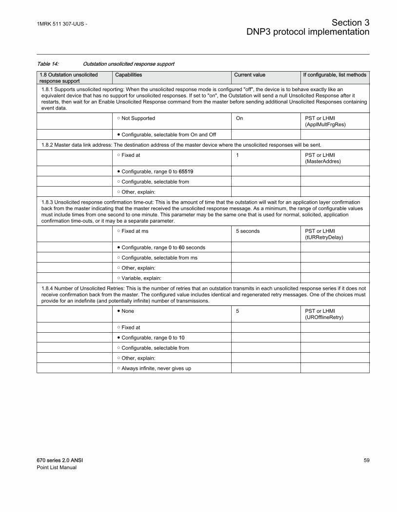
Table 14: Outstation unsolicited response support
1.8 Outstation unsolicitedresponse support
Capabilities Current value If configurable, list methods
1.8.1 Supports unsolicited reporting: When the unsolicited response mode is configured "off", the device is to behave exactly like anequivalent device that has no support for unsolicited responses. If set to "on", the Outstation will send a null Unsolicited Response after itrestarts, then wait for an Enable Unsolicited Response command from the master before sending additional Unsolicited Responses containingevent data.
○ Not Supported On PST or LHMI(ApplMultFrgRes)
● Configurable, selectable from On and Off
1.8.2 Master data link address: The destination address of the master device where the unsolicited responses will be sent.
○ Fixed at 1 PST or LHMI(MasterAddres)
● Configurable, range 0 to 65519
○ Configurable, selectable from
○ Other, explain:
1.8.3 Unsolicited response confirmation time-out: This is the amount of time that the outstation will wait for an application layer confirmationback from the master indicating that the master received the unsolicited response message. As a minimum, the range of configurable valuesmust include times from one second to one minute. This parameter may be the same one that is used for normal, solicited, applicationconfirmation time-outs, or it may be a separate parameter.
○ Fixed at ms 5 seconds PST or LHMI(tURRetryDelay)
● Configurable, range 0 to 60 seconds
○ Configurable, selectable from ms
○ Other, explain:
○ Variable, explain:
1.8.4 Number of Unsolicited Retries: This is the number of retries that an outstation transmits in each unsolicited response series if it does notreceive confirmation back from the master. The configured value includes identical and regenerated retry messages. One of the choices mustprovide for an indefinite (and potentially infinite) number of transmissions.
● None 5 PST or LHMI(UROfflineRetry)
○ Fixed at
● Configurable, range 0 to 10
○ Configurable, selectable from
○ Other, explain:
○ Always infinite, never gives up
1MRK 511 307-UUS - Section 3DNP3 protocol implementation
670 series 2.0 ANSI 59Point List Manual
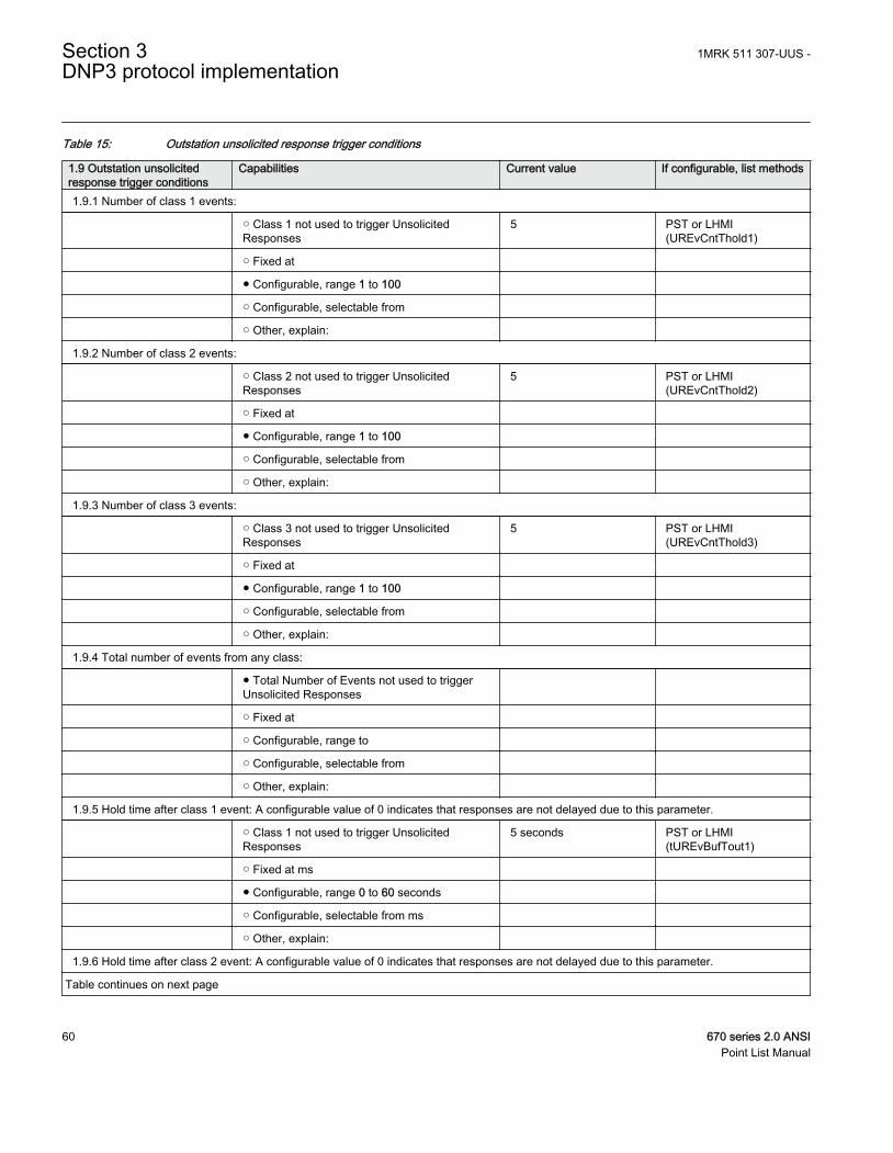
Table 15: Outstation unsolicited response trigger conditions
1.9 Outstation unsolicitedresponse trigger conditions
Capabilities Current value If configurable, list methods
1.9.1 Number of class 1 events:
○ Class 1 not used to trigger UnsolicitedResponses
5 PST or LHMI(UREvCntThold1)
○ Fixed at
● Configurable, range 1 to 100
○ Configurable, selectable from
○ Other, explain:
1.9.2 Number of class 2 events:
○ Class 2 not used to trigger UnsolicitedResponses
5 PST or LHMI(UREvCntThold2)
○ Fixed at
● Configurable, range 1 to 100
○ Configurable, selectable from
○ Other, explain:
1.9.3 Number of class 3 events:
○ Class 3 not used to trigger UnsolicitedResponses
5 PST or LHMI(UREvCntThold3)
○ Fixed at
● Configurable, range 1 to 100
○ Configurable, selectable from
○ Other, explain:
1.9.4 Total number of events from any class:
● Total Number of Events not used to triggerUnsolicited Responses
○ Fixed at
○ Configurable, range to
○ Configurable, selectable from
○ Other, explain:
1.9.5 Hold time after class 1 event: A configurable value of 0 indicates that responses are not delayed due to this parameter.
○ Class 1 not used to trigger UnsolicitedResponses
5 seconds PST or LHMI(tUREvBufTout1)
○ Fixed at ms
● Configurable, range 0 to 60 seconds
○ Configurable, selectable from ms
○ Other, explain:
1.9.6 Hold time after class 2 event: A configurable value of 0 indicates that responses are not delayed due to this parameter.
Table continues on next page
Section 3 1MRK 511 307-UUS -DNP3 protocol implementation
60 670 series 2.0 ANSIPoint List Manual
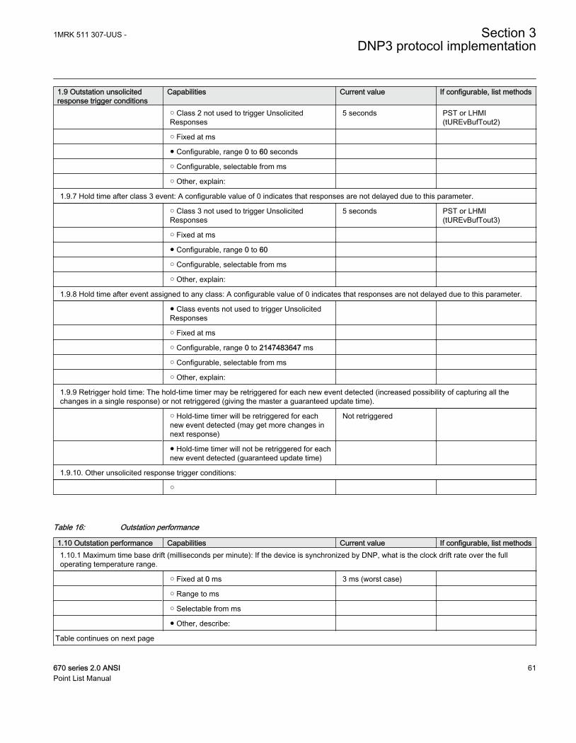
1.9 Outstation unsolicitedresponse trigger conditions
Capabilities Current value If configurable, list methods
○ Class 2 not used to trigger UnsolicitedResponses
5 seconds PST or LHMI(tUREvBufTout2)
○ Fixed at ms
● Configurable, range 0 to 60 seconds
○ Configurable, selectable from ms
○ Other, explain:
1.9.7 Hold time after class 3 event: A configurable value of 0 indicates that responses are not delayed due to this parameter.
○ Class 3 not used to trigger UnsolicitedResponses
5 seconds PST or LHMI(tUREvBufTout3)
○ Fixed at ms
● Configurable, range 0 to 60
○ Configurable, selectable from ms
○ Other, explain:
1.9.8 Hold time after event assigned to any class: A configurable value of 0 indicates that responses are not delayed due to this parameter.
● Class events not used to trigger UnsolicitedResponses
○ Fixed at ms
○ Configurable, range 0 to 2147483647 ms
○ Configurable, selectable from ms
○ Other, explain:
1.9.9 Retrigger hold time: The hold-time timer may be retriggered for each new event detected (increased possibility of capturing all thechanges in a single response) or not retriggered (giving the master a guaranteed update time).
○ Hold-time timer will be retriggered for eachnew event detected (may get more changes innext response)
Not retriggered
● Hold-time timer will not be retriggered for eachnew event detected (guaranteed update time)
1.9.10. Other unsolicited response trigger conditions:
○
Table 16: Outstation performance
1.10 Outstation performance Capabilities Current value If configurable, list methods1.10.1 Maximum time base drift (milliseconds per minute): If the device is synchronized by DNP, what is the clock drift rate over the fulloperating temperature range.
○ Fixed at 0 ms 3 ms (worst case)
○ Range to ms
○ Selectable from ms
● Other, describe:
Table continues on next page
1MRK 511 307-UUS - Section 3DNP3 protocol implementation
670 series 2.0 ANSI 61Point List Manual
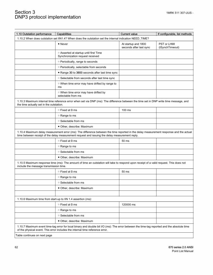
1.10 Outstation performance Capabilities Current value If configurable, list methods1.10.2 When does outstation set IIN1.4? When does the outstation set the internal indication NEED_TIME?
● Never At startup and 1800seconds after last sync
PST or LHMI(tSynchTimeout)
○ Asserted at startup until first TimeSynchronization request received
○ Periodically, range to seconds
○ Periodically, selectable from seconds
● Range 30 to 3600 seconds after last time sync
○ Selectable from seconds after last time sync
○ When time error may have drifted by range toms
○ When time error may have drifted byselectable from ms
1.10.3 Maximum internal time reference error when set via DNP (ms): The difference between the time set in DNP write time message, andthe time actually set in the outstation.
○ Fixed at 0 ms 100 ms
○ Range to ms
○ Selectable from ms
● Other, describe: Maximum
1.10.4 Maximum delay measurement error (ms): The difference between the time reported in the delay measurement response and the actualtime between receipt of the delay measurement request and issuing the delay measurement reply.
○ Fixed at 0 ms 50 ms
○ Range to ms
○ Selectable from ms
● Other, describe: Maximum
1.10.5 Maximum response time (ms): The amount of time an outstation will take to respond upon receipt of a valid request. This does notinclude the message transmission time.
○ Fixed at 0 ms 50 ms
○ Range to ms
○ Selectable from ms
● Other, describe: Maximum
1.10.6 Maximum time from start-up to IIN 1.4 assertion (ms):
○ Fixed at 0 ms 120000 ms
○ Range to ms
○ Selectable from ms
● Other, describe: Maximum
1.10.7 Maximum event time-tag error for local binary and double bit I/O (ms): The error between the time-tag reported and the absolute timeof the physical event. This error includes the internal time reference error.
Table continues on next page
Section 3 1MRK 511 307-UUS -DNP3 protocol implementation
62 670 series 2.0 ANSIPoint List Manual
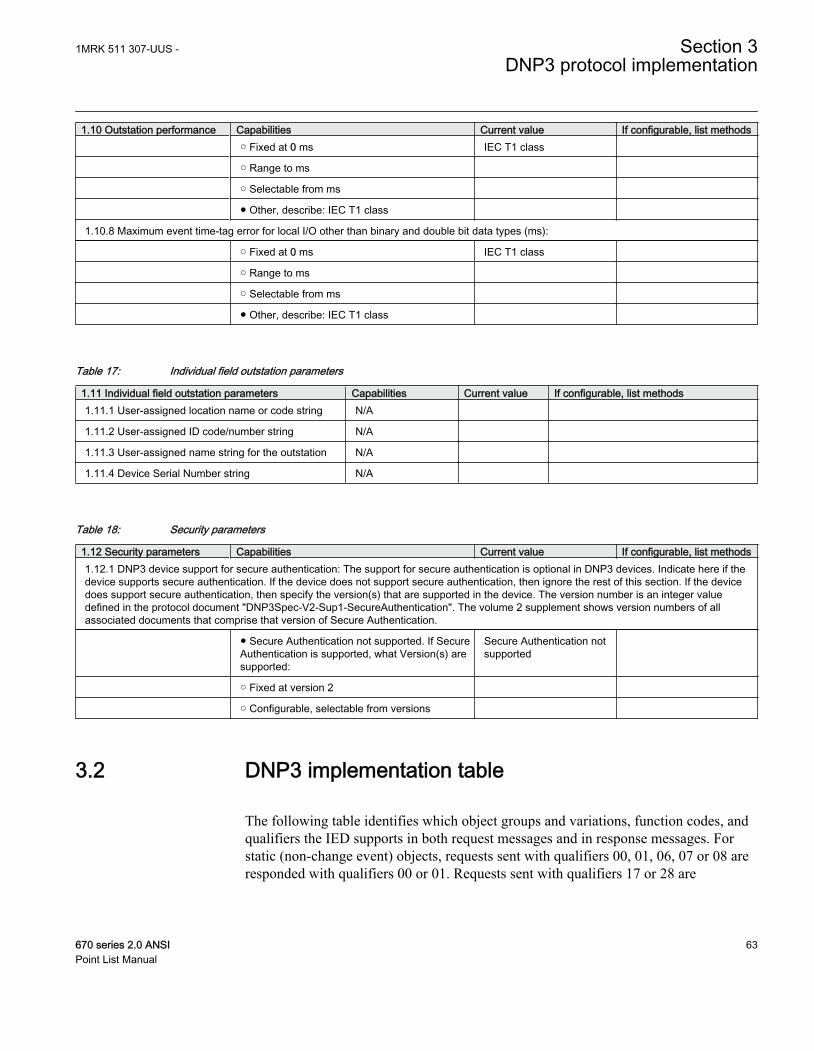
1.10 Outstation performance Capabilities Current value If configurable, list methods ○ Fixed at 0 ms IEC T1 class
○ Range to ms
○ Selectable from ms
● Other, describe: IEC T1 class
1.10.8 Maximum event time-tag error for local I/O other than binary and double bit data types (ms):
○ Fixed at 0 ms IEC T1 class
○ Range to ms
○ Selectable from ms
● Other, describe: IEC T1 class
Table 17: Individual field outstation parameters
1.11 Individual field outstation parameters Capabilities Current value If configurable, list methods1.11.1 User-assigned location name or code string N/A
1.11.2 User-assigned ID code/number string N/A
1.11.3 User-assigned name string for the outstation N/A
1.11.4 Device Serial Number string N/A
Table 18: Security parameters
1.12 Security parameters Capabilities Current value If configurable, list methods1.12.1 DNP3 device support for secure authentication: The support for secure authentication is optional in DNP3 devices. Indicate here if thedevice supports secure authentication. If the device does not support secure authentication, then ignore the rest of this section. If the devicedoes support secure authentication, then specify the version(s) that are supported in the device. The version number is an integer valuedefined in the protocol document "DNP3Spec-V2-Sup1-SecureAuthentication". The volume 2 supplement shows version numbers of allassociated documents that comprise that version of Secure Authentication.
● Secure Authentication not supported. If SecureAuthentication is supported, what Version(s) aresupported:
Secure Authentication notsupported
○ Fixed at version 2
○ Configurable, selectable from versions
3.2 DNP3 implementation table
The following table identifies which object groups and variations, function codes, andqualifiers the IED supports in both request messages and in response messages. Forstatic (non-change event) objects, requests sent with qualifiers 00, 01, 06, 07 or 08 areresponded with qualifiers 00 or 01. Requests sent with qualifiers 17 or 28 are
1MRK 511 307-UUS - Section 3DNP3 protocol implementation
670 series 2.0 ANSI 63Point List Manual
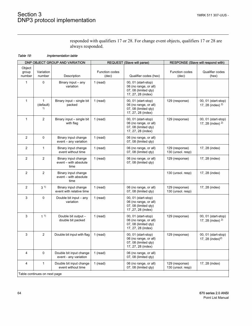
responded with qualifiers 17 or 28. For change event objects, qualifiers 17 or 28 arealways responded.
Table 19: Implementation table
DNP OBJECT GROUP AND VARIATION REQUEST (Slave will parse) RESPONSE (Slave will respond with)Objectgroup
numberVariationnumber Description
Function codes(dec) Qualifier codes (hex)
Function codes(dec)
Qualifier codes(hex)
1 0 Binary input – anyvariation
1 (read) 00, 01 (start-stop)06 (no range, or all)07, 08 (limited qty)17, 27, 28 (index)
1 1(default)
1)
Binary input – single bitpacked
1 (read) 00, 01 (start-stop)06 (no range, or all)07, 08 (limited qty)17, 27, 28 (index)
129 (response) 00, 01 (start-stop)17, 28 (index) 2)
1 2 Binary input – single bitwith flag
1 (read) 00, 01 (start-stop)06 (no range, or all)07, 08 (limited qty)17, 27, 28 (index)
129 (response) 00, 01 (start-stop)17, 28 (index) 2)
2 0 Binary input changeevent – any variation
1 (read) 06 (no range, or all)07, 08 (limited qty)
2 1 Binary input changeevent without time
1 (read) 06 (no range, or all)07, 08 (limited qty)
129 (response)130 (unsol. resp)
17, 28 (index)
2 2 Binary input changeevent – with absolute
time
1 (read) 06 (no range, or all)07, 08 (limited qty)
129 (response) 17, 28 (index)
2 2 Binary input changeevent – with absolute
time
130 (unsol. resp) 17, 28 (index)
2 3 1) Binary input changeevent with relative time
1 (read) 06 (no range, or all)07, 08 (limited qty)
129 (response)130 (unsol. resp)
17, 28 (index)
3 0 Double bit input – anyvariation
1 (read) 00, 01 (start-stop)06 (no range, or all)07, 08 (limited qty)17 ,27, 28 (index)
3 1 1) Double bit output –double bit packed
1 (read) 00, 01 (start-stop)06 (no range, or all)07, 08 (limited qty)17, 27, 28 (index)
129 (response) 00, 01 (start-stop)17, 28 (index) 2)
3 2 Double bit input with flag 1 (read) 00, 01 (start-stop)06 (no range, or all)07, 08 (limited qty)17, 27, 28 (index)
129 (response) 00, 01 (start-stop)17, 28 (index)2)
4 0 Double bit input changeevent - any variation
1 (read) 06 (no range, or all)07, 08 (limited qty)
4 1 Double bit input changeevent without time
1 (read) 06 (no range, or all)07, 08 (limited qty)
129 (response)130 (unsol. resp)
17, 28 (index)
Table continues on next page
Section 3 1MRK 511 307-UUS -DNP3 protocol implementation
64 670 series 2.0 ANSIPoint List Manual
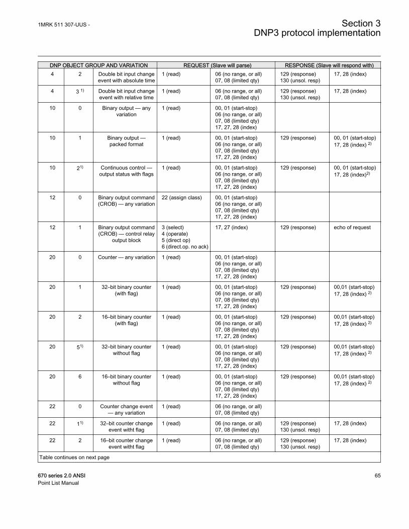
DNP OBJECT GROUP AND VARIATION REQUEST (Slave will parse) RESPONSE (Slave will respond with)4 2 Double bit input change
event with absolute time1 (read) 06 (no range, or all)
07, 08 (limited qty)129 (response)130 (unsol. resp)
17, 28 (index)
4 3 1) Double bit input changeevent with relative time
1 (read) 06 (no range, or all)07, 08 (limited qty)
129 (response)130 (unsol. resp)
17, 28 (index)
10 0 Binary output — anyvariation
1 (read) 00, 01 (start-stop)06 (no range, or all)07, 08 (limited qty)17, 27, 28 (index)
10 1 Binary output —packed format
1 (read) 00, 01 (start-stop)06 (no range, or all)07, 08 (limited qty)17, 27, 28 (index)
129 (response) 00, 01 (start-stop)17, 28 (index) 2)
10 21) Continuous control —output status with flags
1 (read) 00, 01 (start-stop)06 (no range, or all)07, 08 (limited qty)17, 27, 28 (index)
129 (response) 00, 01 (start-stop)17, 28 (index)2)
12 0 Binary output command(CROB) — any variation
22 (assign class) 00, 01 (start-stop)06 (no range, or all)07, 08 (limited qty)17, 27, 28 (index)
12 1 Binary output command(CROB) — control relay
output block
3 (select)4 (operate)5 (direct op)6 (direct.op. no ack)
17, 27 (index) 129 (response) echo of request
20 0 Counter — any variation 1 (read) 00, 01 (start-stop)06 (no range, or all)07, 08 (limited qty)17, 27, 28 (index)
20 1 32–bit binary counter(with flag)
1 (read) 00, 01 (start-stop)06 (no range, or all)07, 08 (limited qty)17, 27, 28 (index)
129 (response) 00,01 (start-stop)17, 28 (index) 2)
20 2 16–bit binary counter(with flag)
1 (read) 00, 01 (start-stop)06 (no range, or all)07, 08 (limited qty)17, 27, 28 (index)
129 (response) 00,01 (start-stop)17, 28 (index) 2)
20 51) 32–bit binary counterwithout flag
1 (read) 00, 01 (start-stop)06 (no range, or all)07, 08 (limited qty)17, 27, 28 (index)
129 (response) 00,01 (start-stop)17, 28 (index) 2)
20 6 16–bit binary counterwithout flag
1 (read) 00, 01 (start-stop)06 (no range, or all)07, 08 (limited qty)17, 27, 28 (index)
129 (response) 00,01 (start-stop)17, 28 (index) 2)
22 0 Counter change event— any variation
1 (read) 06 (no range, or all)07, 08 (limited qty)
22 11) 32–bit counter changeevent witht flag
1 (read) 06 (no range, or all)07, 08 (limited qty)
129 (response)130 (unsol. resp)
17, 28 (index)
22 2 16–bit counter changeevent witht flag
1 (read) 06 (no range, or all)07, 08 (limited qty)
129 (response)130 (unsol. resp)
17, 28 (index)
Table continues on next page
1MRK 511 307-UUS - Section 3DNP3 protocol implementation
670 series 2.0 ANSI 65Point List Manual
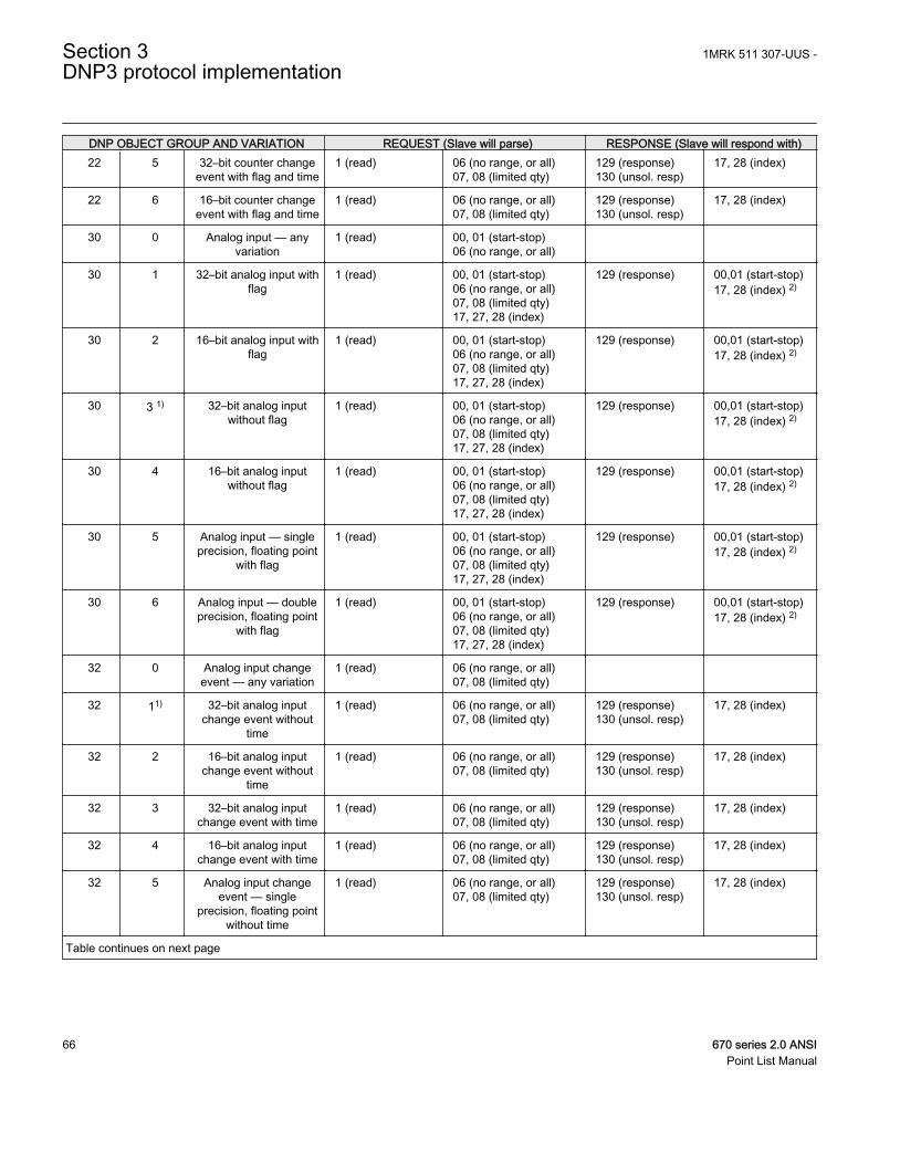
DNP OBJECT GROUP AND VARIATION REQUEST (Slave will parse) RESPONSE (Slave will respond with)22 5 32–bit counter change
event with flag and time1 (read) 06 (no range, or all)
07, 08 (limited qty)129 (response)130 (unsol. resp)
17, 28 (index)
22 6 16–bit counter changeevent with flag and time
1 (read) 06 (no range, or all)07, 08 (limited qty)
129 (response)130 (unsol. resp)
17, 28 (index)
30 0 Analog input — anyvariation
1 (read) 00, 01 (start-stop)06 (no range, or all)
30 1 32–bit analog input withflag
1 (read) 00, 01 (start-stop)06 (no range, or all)07, 08 (limited qty)17, 27, 28 (index)
129 (response) 00,01 (start-stop)17, 28 (index) 2)
30 2 16–bit analog input withflag
1 (read) 00, 01 (start-stop)06 (no range, or all)07, 08 (limited qty)17, 27, 28 (index)
129 (response) 00,01 (start-stop)17, 28 (index) 2)
30 3 1) 32–bit analog inputwithout flag
1 (read) 00, 01 (start-stop)06 (no range, or all)07, 08 (limited qty)17, 27, 28 (index)
129 (response) 00,01 (start-stop)17, 28 (index) 2)
30 4 16–bit analog inputwithout flag
1 (read) 00, 01 (start-stop)06 (no range, or all)07, 08 (limited qty)17, 27, 28 (index)
129 (response) 00,01 (start-stop)17, 28 (index) 2)
30 5 Analog input — singleprecision, floating point
with flag
1 (read) 00, 01 (start-stop)06 (no range, or all)07, 08 (limited qty)17, 27, 28 (index)
129 (response) 00,01 (start-stop)17, 28 (index) 2)
30 6 Analog input — doubleprecision, floating point
with flag
1 (read) 00, 01 (start-stop)06 (no range, or all)07, 08 (limited qty)17, 27, 28 (index)
129 (response) 00,01 (start-stop)17, 28 (index) 2)
32 0 Analog input changeevent — any variation
1 (read) 06 (no range, or all)07, 08 (limited qty)
32 11) 32–bit analog inputchange event without
time
1 (read) 06 (no range, or all)07, 08 (limited qty)
129 (response)130 (unsol. resp)
17, 28 (index)
32 2 16–bit analog inputchange event without
time
1 (read) 06 (no range, or all)07, 08 (limited qty)
129 (response)130 (unsol. resp)
17, 28 (index)
32 3 32–bit analog inputchange event with time
1 (read) 06 (no range, or all)07, 08 (limited qty)
129 (response)130 (unsol. resp)
17, 28 (index)
32 4 16–bit analog inputchange event with time
1 (read) 06 (no range, or all)07, 08 (limited qty)
129 (response)130 (unsol. resp)
17, 28 (index)
32 5 Analog input changeevent — single
precision, floating pointwithout time
1 (read) 06 (no range, or all)07, 08 (limited qty)
129 (response)130 (unsol. resp)
17, 28 (index)
Table continues on next page
Section 3 1MRK 511 307-UUS -DNP3 protocol implementation
66 670 series 2.0 ANSIPoint List Manual
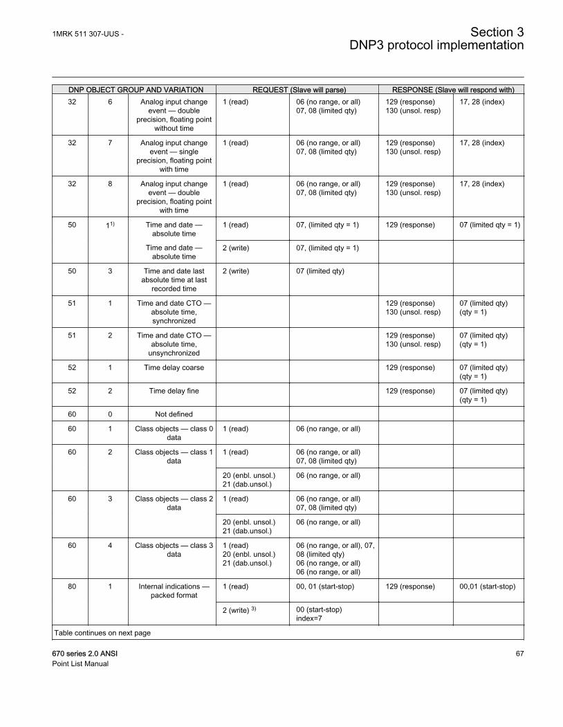
DNP OBJECT GROUP AND VARIATION REQUEST (Slave will parse) RESPONSE (Slave will respond with)32 6 Analog input change
event — doubleprecision, floating point
without time
1 (read) 06 (no range, or all)07, 08 (limited qty)
129 (response)130 (unsol. resp)
17, 28 (index)
32 7 Analog input changeevent — single
precision, floating pointwith time
1 (read) 06 (no range, or all)07, 08 (limited qty)
129 (response)130 (unsol. resp)
17, 28 (index)
32 8 Analog input changeevent — double
precision, floating pointwith time
1 (read) 06 (no range, or all)07, 08 (limited qty)
129 (response)130 (unsol. resp)
17, 28 (index)
50 11) Time and date —absolute time
1 (read) 07, (limited qty = 1) 129 (response) 07 (limited qty = 1)
Time and date —absolute time
2 (write) 07, (limited qty = 1)
50 3 Time and date lastabsolute time at last
recorded time
2 (write) 07 (limited qty)
51 1 Time and date CTO —absolute time,synchronized
129 (response)130 (unsol. resp)
07 (limited qty)(qty = 1)
51 2 Time and date CTO —absolute time,
unsynchronized
129 (response)130 (unsol. resp)
07 (limited qty)(qty = 1)
52 1 Time delay coarse 129 (response) 07 (limited qty)(qty = 1)
52 2 Time delay fine 129 (response) 07 (limited qty)(qty = 1)
60 0 Not defined
60 1 Class objects — class 0data
1 (read) 06 (no range, or all)
60 2 Class objects — class 1data
1 (read) 06 (no range, or all)07, 08 (limited qty)
20 (enbl. unsol.)21 (dab.unsol.)
06 (no range, or all)
60 3 Class objects — class 2data
1 (read) 06 (no range, or all)07, 08 (limited qty)
20 (enbl. unsol.)21 (dab.unsol.)
06 (no range, or all)
60 4 Class objects — class 3data
1 (read)20 (enbl. unsol.)21 (dab.unsol.)
06 (no range, or all), 07,08 (limited qty)06 (no range, or all)06 (no range, or all)
80 1 Internal indications —packed format
1 (read) 00, 01 (start-stop) 129 (response) 00,01 (start-stop)
2 (write) 3) 00 (start-stop)index=7
Table continues on next page
1MRK 511 307-UUS - Section 3DNP3 protocol implementation
670 series 2.0 ANSI 67Point List Manual
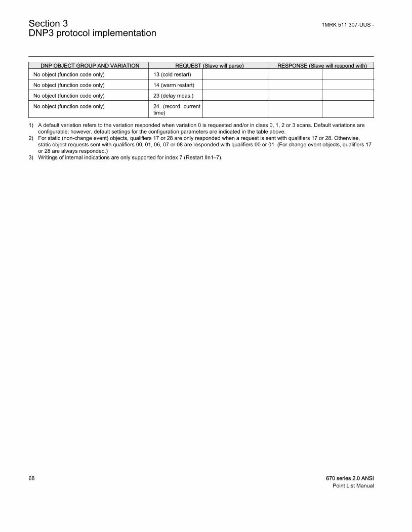
DNP OBJECT GROUP AND VARIATION REQUEST (Slave will parse) RESPONSE (Slave will respond with)No object (function code only) 13 (cold restart)
No object (function code only) 14 (warm restart)
No object (function code only) 23 (delay meas.)
No object (function code only) 24 (record currenttime)
1) A default variation refers to the variation responded when variation 0 is requested and/or in class 0, 1, 2 or 3 scans. Default variations areconfigurable; however, default settings for the configuration parameters are indicated in the table above.
2) For static (non-change event) objects, qualifiers 17 or 28 are only responded when a request is sent with qualifiers 17 or 28. Otherwise,static object requests sent with qualifiers 00, 01, 06, 07 or 08 are responded with qualifiers 00 or 01. (For change event objects, qualifiers 17or 28 are always responded.)
3) Writings of internal indications are only supported for index 7 (Restart IIn1–7).
Section 3 1MRK 511 307-UUS -DNP3 protocol implementation
68 670 series 2.0 ANSIPoint List Manual

Section 4 Glossary
4.1 Glossary
AC Alternating current
ACC Actual channel
ACT Application configuration tool within PCM600
A/D converter Analog-to-digital converter
ADBS Amplitude deadband supervision
ADM Analog digital conversion module, with time synchronization
AI Analog input
ANSI American National Standards Institute
AR Autoreclosing
ASCT Auxiliary summation current transformer
ASD Adaptive signal detection
ASDU Application service data unit
AWG American Wire Gauge standard
BBP Busbar protection
BFOC/2,5 Bayonet fibre optic connector
BFP Breaker failure protection
BI Binary input
BIM Binary input module
BOM Binary output module
BOS Binary outputs status
BR External bistable relay
BS British Standards
BSR Binary signal transfer function, receiver blocks
BST Binary signal transfer function, transmit blocks
1MRK 511 307-UUS - Section 4Glossary
670 series 2.0 ANSI 69Point List Manual
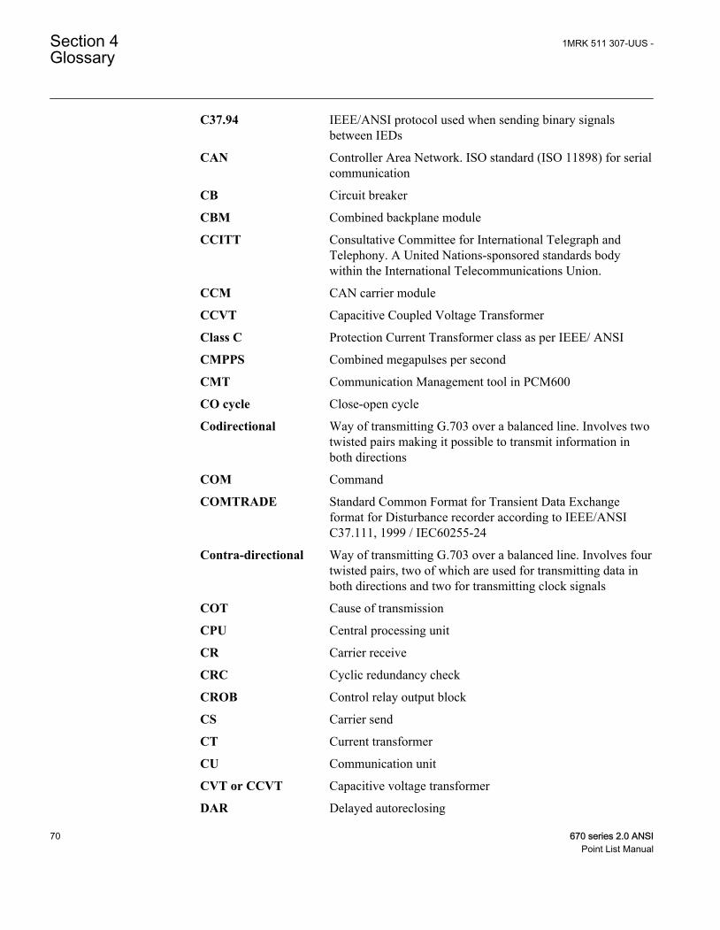
C37.94 IEEE/ANSI protocol used when sending binary signalsbetween IEDs
CAN Controller Area Network. ISO standard (ISO 11898) for serialcommunication
CB Circuit breaker
CBM Combined backplane module
CCITT Consultative Committee for International Telegraph andTelephony. A United Nations-sponsored standards bodywithin the International Telecommunications Union.
CCM CAN carrier module
CCVT Capacitive Coupled Voltage Transformer
Class C Protection Current Transformer class as per IEEE/ ANSI
CMPPS Combined megapulses per second
CMT Communication Management tool in PCM600
CO cycle Close-open cycle
Codirectional Way of transmitting G.703 over a balanced line. Involves twotwisted pairs making it possible to transmit information inboth directions
COM Command
COMTRADE Standard Common Format for Transient Data Exchangeformat for Disturbance recorder according to IEEE/ANSIC37.111, 1999 / IEC60255-24
Contra-directional Way of transmitting G.703 over a balanced line. Involves fourtwisted pairs, two of which are used for transmitting data inboth directions and two for transmitting clock signals
COT Cause of transmission
CPU Central processing unit
CR Carrier receive
CRC Cyclic redundancy check
CROB Control relay output block
CS Carrier send
CT Current transformer
CU Communication unit
CVT or CCVT Capacitive voltage transformer
DAR Delayed autoreclosing
Section 4 1MRK 511 307-UUS -Glossary
70 670 series 2.0 ANSIPoint List Manual
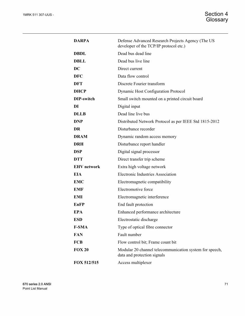
DARPA Defense Advanced Research Projects Agency (The USdeveloper of the TCP/IP protocol etc.)
DBDL Dead bus dead line
DBLL Dead bus live line
DC Direct current
DFC Data flow control
DFT Discrete Fourier transform
DHCP Dynamic Host Configuration Protocol
DIP-switch Small switch mounted on a printed circuit board
DI Digital input
DLLB Dead line live bus
DNP Distributed Network Protocol as per IEEE Std 1815-2012
DR Disturbance recorder
DRAM Dynamic random access memory
DRH Disturbance report handler
DSP Digital signal processor
DTT Direct transfer trip scheme
EHV network Extra high voltage network
EIA Electronic Industries Association
EMC Electromagnetic compatibility
EMF Electromotive force
EMI Electromagnetic interference
EnFP End fault protection
EPA Enhanced performance architecture
ESD Electrostatic discharge
F-SMA Type of optical fibre connector
FAN Fault number
FCB Flow control bit; Frame count bit
FOX 20 Modular 20 channel telecommunication system for speech,data and protection signals
FOX 512/515 Access multiplexer
1MRK 511 307-UUS - Section 4Glossary
670 series 2.0 ANSI 71Point List Manual
FOX 6Plus Compact time-division multiplexer for the transmission of upto seven duplex channels of digital data over optical fibers
FUN Function type
G.703 Electrical and functional description for digital lines used bylocal telephone companies. Can be transported over balancedand unbalanced lines
GCM Communication interface module with carrier of GPS receivermodule
GDE Graphical display editor within PCM600
GI General interrogation command
GIS Gas-insulated switchgear
GOOSE Generic object-oriented substation event
GPS Global positioning system
GSAL Generic security application
HDLC protocol High-level data link control, protocol based on the HDLCstandard
HFBR connector type Plastic fiber connector
HMI Human-machine interface
HSAR High speed autoreclosing
HV High-voltage
HVDC High-voltage direct current
IDBS Integrating deadband supervision
IEC International Electrical Committee
IEC 60044-6 IEC Standard, Instrument transformers – Part 6: Requirementsfor protective current transformers for transient performance
IEC 60870-5-103 Communication standard for protection equipment. A serialmaster/slave protocol for point-to-point communication
IEC 61850 Substation automation communication standard
IEC 61850–8–1 Communication protocol standard
IEEE Institute of Electrical and Electronics Engineers
IEEE 802.12 A network technology standard that provides 100 Mbits/s ontwisted-pair or optical fiber cable
IEEE P1386.1 PCI Mezzanine Card (PMC) standard for local bus modules.References the CMC (IEEE P1386, also known as CommonMezzanine Card) standard for the mechanics and the PCI
Section 4 1MRK 511 307-UUS -Glossary
72 670 series 2.0 ANSIPoint List Manual
specifications from the PCI SIG (Special Interest Group) forthe electrical EMF (Electromotive force).
IEEE 1686 Standard for Substation Intelligent Electronic Devices (IEDs)Cyber Security Capabilities
IED Intelligent electronic device
I-GIS Intelligent gas-insulated switchgear
IOM Binary input/output module
Instance When several occurrences of the same function are availablein the IED, they are referred to as instances of that function.One instance of a function is identical to another of the samekind but has a different number in the IED user interfaces.The word "instance" is sometimes defined as an item ofinformation that is representative of a type. In the same wayan instance of a function in the IED is representative of a typeof function.
IP 1. Internet protocol. The network layer for the TCP/IPprotocol suite widely used on Ethernet networks. IP is aconnectionless, best-effort packet-switching protocol. Itprovides packet routing, fragmentation and reassemblythrough the data link layer.2. Ingression protection, according to IEC 60529
IP 20 Ingression protection, according to IEC 60529, levelIP20- Protected against solid foreign objects of 12.5mmdiameter and greater.
IP 40 Ingression protection, according to IEC 60529, level IP40-Protected against solid foreign objects of 1mm diameter andgreater.
IP 54 Ingression protection, according to IEC 60529, levelIP54-Dust-protected, protected against splashing water.
IRF Internal failure signal
IRIG-B: InterRange Instrumentation Group Time code format B,standard 200
ITU International Telecommunications Union
LAN Local area network
LIB 520 High-voltage software module
LCD Liquid crystal display
LDCM Line differential communication module
1MRK 511 307-UUS - Section 4Glossary
670 series 2.0 ANSI 73Point List Manual
LDD Local detection device
LED Light-emitting diode
LNT LON network tool
LON Local operating network
MCB Miniature circuit breaker
MCM Mezzanine carrier module
MIM Milli-ampere module
MPM Main processing module
MVAL Value of measurement
MVB Multifunction vehicle bus. Standardized serial bus originallydeveloped for use in trains.
NCC National Control Centre
NOF Number of grid faults
NUM Numerical module
OCO cycle Open-close-open cycle
OCP Overcurrent protection
OEM Optical Ethernet module
OLTC On-load tap changer
OTEV Disturbance data recording initiated by other event than start/pick-up
OV Overvoltage
Overreach A term used to describe how the relay behaves during a faultcondition. For example, a distance relay is overreaching whenthe impedance presented to it is smaller than the apparentimpedance to the fault applied to the balance point, that is, theset reach. The relay “sees” the fault but perhaps it should nothave seen it.
PCI Peripheral component interconnect, a local data bus
PCM Pulse code modulation
PCM600 Protection and control IED manager
PC-MIP Mezzanine card standard
PMC PCI Mezzanine card
POR Permissive overreach
POTT Permissive overreach transfer trip
Section 4 1MRK 511 307-UUS -Glossary
74 670 series 2.0 ANSIPoint List Manual
Process bus Bus or LAN used at the process level, that is, in nearproximity to the measured and/or controlled components
PSM Power supply module
PST Parameter setting tool within PCM600
PT ratio Potential transformer or voltage transformer ratio
PUTT Permissive underreach transfer trip
RASC Synchrocheck relay, COMBIFLEX
RCA Relay characteristic angle
RISC Reduced instruction set computer
RMS value Root mean square value
RS422 A balanced serial interface for the transmission of digital datain point-to-point connections
RS485 Serial link according to EIA standard RS485
RTC Real-time clock
RTU Remote terminal unit
SA Substation Automation
SBO Select-before-operate
SC Switch or push button to close
SCL Short circuit location
SCS Station control system
SCADA Supervision, control and data acquisition
SCT System configuration tool according to standard IEC 61850
SDU Service data unit
SLM Serial communication module.
SMA connector Subminiature version A, A threaded connector with constantimpedance.
SMT Signal matrix tool within PCM600
SMS Station monitoring system
SNTP Simple network time protocol – is used to synchronizecomputer clocks on local area networks. This reduces therequirement to have accurate hardware clocks in everyembedded system in a network. Each embedded node caninstead synchronize with a remote clock, providing therequired accuracy.
1MRK 511 307-UUS - Section 4Glossary
670 series 2.0 ANSI 75Point List Manual
SOF Status of fault
SPA Strömberg Protection Acquisition (SPA), a serial master/slaveprotocol for point-to-point communication
SRY Switch for CB ready condition
ST Switch or push button to trip
Starpoint Neutral/Wye point of transformer or generator
SVC Static VAr compensation
TC Trip coil
TCS Trip circuit supervision
TCP Transmission control protocol. The most common transportlayer protocol used on Ethernet and the Internet.
TCP/IP Transmission control protocol over Internet Protocol. The defacto standard Ethernet protocols incorporated into 4.2BSDUnix. TCP/IP was developed by DARPA for Internet workingand encompasses both network layer and transport layerprotocols. While TCP and IP specify two protocols at specificprotocol layers, TCP/IP is often used to refer to the entire USDepartment of Defense protocol suite based upon these,including Telnet, FTP, UDP and RDP.
TEF Time delayed gound-fault protection function
TM Transmit (disturbance data)
TNC connector Threaded Neill-Concelman, a threaded constant impedanceversion of a BNC connector
TP Trip (recorded fault)
TPZ, TPY, TPX, TPS Current transformer class according to IEC
TRM Transformer Module. This module transforms currents andvoltages taken from the process into levels suitable for furthersignal processing.
TYP Type identification
UMT User management tool
Underreach A term used to describe how the relay behaves during a faultcondition. For example, a distance relay is underreachingwhen the impedance presented to it is greater than theapparent impedance to the fault applied to the balance point,that is, the set reach. The relay does not “see” the fault butperhaps it should have seen it. See also Overreach.
Section 4 1MRK 511 307-UUS -Glossary
76 670 series 2.0 ANSIPoint List Manual
UTC Coordinated Universal Time. A coordinated time scale,maintained by the Bureau International des Poids et Mesures(BIPM), which forms the basis of a coordinated disseminationof standard frequencies and time signals. UTC is derived fromInternational Atomic Time (TAI) by the addition of a wholenumber of "leap seconds" to synchronize it with UniversalTime 1 (UT1), thus allowing for the eccentricity of the Earth'sorbit, the rotational axis tilt (23.5 degrees), but still showingthe Earth's irregular rotation, on which UT1 is based. TheCoordinated Universal Time is expressed using a 24-hourclock, and uses the Gregorian calendar. It is used foraeroplane and ship navigation, where it is also sometimesknown by the military name, "Zulu time." "Zulu" in thephonetic alphabet stands for "Z", which stands for longitudezero.
UV Undervoltage
WEI Weak end infeed logic
VT Voltage transformer
X.21 A digital signalling interface primarily used for telecomequipment
3IO Three times zero-sequence current.Often referred to as theresidual or the ground-fault current
3VO Three times the zero sequence voltage. Often referred to asthe residual voltage or the neutral point voltage
1MRK 511 307-UUS - Section 4Glossary
670 series 2.0 ANSI 77Point List Manual

78

79

Contact us
ABB ABSubstation Automation ProductsSE-721 59 Västerås, SwedenPhone +46 (0) 21 32 50 00Fax +46 (0) 21 14 69 18
www.abb.com/substationautomation
1MR
K 5
11 3
07-U
US
-©
Cop
yrig
ht 2
014
AB
B. A
ll rig
hts
rese
rved
.