dnvgl-rp-0043 safety, operation and performance of grid … · 2017-09-28 · changes - current...
TRANSCRIPT
The electronic pdf version of this document, available free of chargefrom http://www.dnvgl.com, is the officially binding version.
DNV GL AS
RECOMMENDED PRACTICE
DNVGL-RP-0043 Edition September 2017
Safety, operation and performance of grid-connected energy storage systems

FOREWORD
DNV GL recommended practices contain sound engineering practice and guidance.
© DNV GL AS September 2017
Any comments may be sent by e-mail to [email protected]
This service document has been prepared based on available knowledge, technology and/or information at the time of issuance of thisdocument. The use of this document by others than DNV GL is at the user's sole risk. DNV GL does not accept any liability or responsibilityfor loss or damages resulting from any use of this document.

Cha
nges
- c
urre
nt
Recommended practice — DNVGL-RP-0043. Edition September 2017 Page 3Safety, operation and performance of grid-connected energy storage systems
DNV GL AS
CHANGES - CURRENT
This document supersedes the December 2017 edition of DNVGL-RP-0043Changes in this document are highlighted in red colour. However, if the changes involve a whole chapter,section or sub-section, normally only the title will be in red colour.
Main changes— The following topics were added or significantly expanded:
— [4.3] Tendering and procurement— [4.4.1] and [4.4.2] Conformity assessment including FAT/SAT testing— [4.4.3] Warranty— [4.9.2] Decommissioning— [6.2.2] Microgrids— [6.5.10] Communication protocols— [7.4.9] Cyber security— [8.5] Greenhouse gas emissions calculation— [10.3] Bankability— [10.4] Residual value.
— Technology-specific recommendations and background were added on (sub-)technologies:
— [7.5.1.2] Lead crystal batteries.— [7.5.1.3] Inorganic lithium ion batteries— [7.5.2.1] Supercapacitors— [7.5.2.4] Compressed air energy storage (CAES)— [7.5.2.5] Liquid air energy storage (LAES).
— [7.5.1.3]: Technology-specific safety recommendations for Li-ion batteries were updated
— [7.4.5] and [7.4.6]: Recommendations regarding first responders, fire considerations and thermalmanagement were updated
— [B.3]: Overview of normative and informative references was actualised and expanded to include therecommended practice (RP) updates described above
— Sec.3 has been expanded with three applications, previously belonging to other categories: ramp ratecontrol, generation peak shaving, capacity firming
— Sec.7 has been reorganised for clarity and a more elaborate introduction was added
— Former Sec. 10 has been turned into App.B
— Former paragraph 5.2's content on levelised cost of storage (LCOS) and life cycle costs were moved to thenew Sec.10
— Paragraph [B.2] (formerly 10.2) was updated and expanded to better reflect the American and Europeansituation.
Editorial correctionsIn addition to the above stated changes, editorial corrections may have been made.

Cha
nges
- c
urre
nt
Recommended practice — DNVGL-RP-0043. Edition September 2017 Page 4Safety, operation and performance of grid-connected energy storage systems
DNV GL AS
AcknowledgementsThis RP was developed in 2015 and updated in 2016-2017 in two respective Joint Industry Projects (JIPs).The work was performed by DNV GL and discussed in regular project meetings and workshops withindividuals from the organisations participating in these projects. They are hereby acknowledged for theirsignificant, valuable and constructive input. In case consensus has not been achievable, DNV GL has soughtto provide acceptable compromise.The JIP consortium of the 2015 edition of this document included the following organisations: JSR Micro,REDT Energy Storage, Energy Canvas, Joulz, Institute for Mechatronic Systems in Mechanical Engineering(Technische Universität Darmstadt), Institute for Power Generation and Storage Systems (RWTH AachenUniversity), Cumulus Energy Storage.The JIP consortium of the 2017 edition of this document included the following organisations: Alaska Centerfor Energy and Power, Alfen, Alevo, ATEPS, Conergy, Datawatt, Enexis, Gaelectric, Highview Power, HybridEurope, Maxwell, PNNL (in support of the U.S. DOE OE energy storage safety strategy), RWTH, Wärtsilä.Furthermore, DNV GL is grateful for the valuable feedback from individuals in the organisations who haveparticipated in the review (hearing) process in 2015 and 2017: Alaska Center for Energy and Power, Alliander,Clean Energy Council, Denchi Power, Ecovat Renewable Energy Technologies, Electricity Storage Network,Enel Ingegneria & Ricerca SpA, GE Energy Storage, GNB Industrial Power (a division of Exide Technologies),Hybrid Europe BV, muGrid Analytics, New York Battery and Energy Storage Technology Consortium (NY-BEST), Norton Rose Fulbright LLP, PNNL, Scholt Energy Control, Scottish and Southern Energy PowerDistribution (SSEPD), UK Power Networks, Younicos and 125 other organisations not explicitly mentionedhere.

Con
tent
s
Recommended practice — DNVGL-RP-0043. Edition September 2017 Page 5Safety, operation and performance of grid-connected energy storage systems
DNV GL AS
CONTENTS
Changes - current...................................................................................................3Acknowledgements.................................................................................4
Section 1 General....................................................................................................81.1 Introduction......................................................................................81.2 Objective...........................................................................................81.3 Scope................................................................................................ 81.4 Structure of this document...............................................................81.5 Relationship to other standardisation activities................................91.6 Abbreviations..................................................................................10
Section 2 Electrical energy storage systems - introduction and definitions...........122.1 Definition of electrical energy storage system................................122.2 Definitions of other terms.............................................................. 22
Section 3 Applications of stationary electrical energy storage systems................ 303.1 General........................................................................................... 303.2 Bulk energy services.......................................................................323.3 Ancillary services............................................................................333.4 Transmission infrastructure services.............................................. 363.5 Distribution infrastructure services................................................ 373.6 Customer energy management services......................................... 373.7 Renewables integration.................................................................. 41
Section 4 Electrical energy storage system life cycle phases................................ 434.1 General........................................................................................... 434.2 Design and planning....................................................................... 444.3 Tendering and procurement............................................................454.4 Manufacturing.................................................................................464.5 Transport and warehousing............................................................ 484.6 Installation and commissioning...................................................... 484.7 Operation........................................................................................ 494.8 Maintenance and repair.................................................................. 504.9 Repurposing and end of life............................................................504.10 Documentation requirements........................................................52
Section 5 Performance indicators......................................................................... 545.1 Power..............................................................................................54
Con
tent
s
Recommended practice — DNVGL-RP-0043. Edition September 2017 Page 6Safety, operation and performance of grid-connected energy storage systems
DNV GL AS
5.2 Energy.............................................................................................565.3 Dynamics........................................................................................ 565.4 Efficiency........................................................................................ 575.5 Reliability, availability.....................................................................59
Section 6 Operation, maintenance, repair.............................................................616.1 General........................................................................................... 616.2 Grid connection aspects..................................................................616.3 Automation..................................................................................... 636.4 Documentation................................................................................646.5 Monitoring and control functions....................................................656.6 Repair............................................................................................. 74
Section 7 Safety.................................................................................................... 757.1 Introduction....................................................................................757.2 Risk assessments............................................................................757.3 Hazards, failure modes and effects.................................................787.4 Safety requirements - technology agnostic.....................................787.5 Safety requirements - technology specific...................................... 877.6 Safety requirements for specific life cycle phases...........................97
Section 8 Environmental analysis........................................................................1018.1 General......................................................................................... 1018.2 Effects of electrical energy storage systems on the environment..1018.3 Effects of environment on electrical energy storage systemoperation............................................................................................ 1048.4 End of life decommissioning and recycling................................... 1068.5 Calculation of greenhouse gas emissions for electrical energystorage systems................................................................................. 107
Section 9 Sizing considerations...........................................................................1099.1 General......................................................................................... 1099.2 Power and energy requirements...................................................1109.3 Siting considerations - geographic circumstances........................ 1119.4 System parameters influencing sizing.......................................... 1129.5 Economic considerations for sizing...............................................1179.6 Configuration of cells, modules and racks.................................... 1179.7 Accommodation, housing, containment of the system and sub-levels.................................................................................................. 119
Section 10 Economics..........................................................................................120
Con
tent
s
Recommended practice — DNVGL-RP-0043. Edition September 2017 Page 7Safety, operation and performance of grid-connected energy storage systems
DNV GL AS
10.1 Life cycle costs........................................................................... 12010.2 Levelised cost of energy and levelised cost of storage................12110.3 Bankability.................................................................................. 12110.4 Residual value.............................................................................122
Appendix A Life cycle cost background information............................................124
Appendix B Regulations, standards and legal issues...........................................126B.1 General......................................................................................... 126B.2 Structure of existing legal frameworks, regulations and codes..... 126B.3 List of normative and informative references............................... 137B.4 Recommendations for storage systems regarding legalframeworks, regulations and standards............................................. 144
Changes - historic...............................................................................................146

Recommended practice — DNVGL-RP-0043. Edition September 2017 Page 8Safety, operation and performance of grid-connected energy storage systems
DNV GL AS
SECTION 1 GENERAL
1.1 IntroductionThe market for grid-connected energy storage systems is rapidly maturing. The successful deployment oftomorrow’s smart electricity grids requires clarity and widespread agreement on issues concerning energystorage systems. Stakeholders agree that joint guidelines, agreements and standards are essential to enableenergy storage to provide the benefits it promises and achieve mass deployment throughout the grid. Thisrecommended practice (RP) aims to accelerate safe and sound implementation of grid-connected energystorage by presenting a guideline for safety, operation and performance of electrical energy storage systems.The information and recommendations in this document comprehensively cover and link all aspects relevantfor grid-connected energy storage.This RP will:
— cover a broad range of energy storage technologies, instead of focusing on one (e.g. batteries)— have a system-level approach, instead of being limited to a small number of key components— have a comprehensive and structured approach.
Future updates of this RP are likely to expand the range of technology-specific recommendations.
1.2 ObjectiveThe objective of this RP is to provide a comprehensive set of recommendations for grid-connected energystorage systems. It aims to be valid in all major markets and geographic regions, for all applications, on alllevels from component to system, covering the entire life cycle. End users, operators and other stakeholderswill be able to take this RP as their single all-encompassing document for such systems, providing them withdirect guidance or referencing through other guidelines and standards.
1.3 ScopeThis RP focuses on three main aspects of grid-connected energy storage: safety, operation and performance.These aspects are assessed for electricity storage systems in general, i.e. a technology agnostic approach).Furthermore, recommendations applying only to specific energy storage technologies are provided wherevernecessary.The RP concerns electrical energy storage systems and technologies. The energy going into and out ofthese systems is electrical energy (electricity), whereas the energy stored in the storage medium may havedifferent forms (see Sec.2). Explicitly out of scope is chemical and thermal energy storage, such as hydrogenstorage or heat storage. Electric vehicles are not currently considered to be grid-connected storage and arenot considered within scope. With respect to the application types of energy storage systems, only homestorage systems are not considered within scope given their distinctly different nature. All electricity storageapplications at the high, medium and low voltage grid level as well as industrial behind-the-meter storageand storage in microgrids and island grids are considered within scope.The proposed guidelines are limited to common requirements, based on worldwide accepted regulation andbest practices like IEC, ISO and IEEE standards. Applying this RP will not guarantee a fully secure storagesystem: new technology will always invalidate previous designs and safe components will not automaticallyresult in a safe system.
1.4 Structure of this documentThe structure of this RP is as follows:
— Sec.2 contains the definitions and abbreviations, including short descriptions of the storage technologieswithin scope.

Recommended practice — DNVGL-RP-0043. Edition September 2017 Page 9Safety, operation and performance of grid-connected energy storage systems
DNV GL AS
— Sec.3 lists the applications of stationary storage systems, grouped in: bulk energy services, ancillaryservices, transmission and distribution infrastructure services, customer energy management andrenewables integration.
— The life cycle phases of a storage system are mentioned in Sec.4: design and planning, transport,installation and commissioning, operation, maintenance and repair, end of life management. Sec.4 alsolists the documentation requirements in each of these phases.
— Sec.5 defines the main performance indicators for qualifying or comparing storage systems for a certainapplication, including performance indicators for economic analyses.
— In Sec.6, operation, maintenance and repair, subjects such as automation considerations, documentationrequirements and requirements for monitoring and control functions are covered.
— Sec.7 on safety design covers generic issues and technology-specific issues, risk analysis methods (e.g.FMEA), and safety considerations with respect to second life (reuse) applications.
— Environmental analysis is addressed in Sec.8, i.e. the effects of storage systems on the environment andeffects of the environment on storage system operation. Special attention is given to the decommissioningand recycling phase.
— In Sec.9 the recommended method of sizing the storage system for a certain application is presented,covering topics like power and energy requirements, siting considerations and economic considerations.
— Recommendations regarding economic considerations of energy storage can be found in Sec.10.— App.A contains background information on life cycle cost calculations.— App.B elaborately addresses existing legal frameworks, regulations and standards, including an overview
list..
1.5 Relationship to other standardisation activitiesThe topics addressed in this RP are (partially) covered by a number of existing standards. This RP aimsto collect the most relevant requirements of all these standards to present a framework guide for grid-connected energy storage with a system-level approach, but including technology-specific aspects whereneeded.This RP is aligned with ongoing international standardisation activities. A special cooperation with IEC TC 120– the technical committee that is also dealing with electrical energy storage systems, but with a technology-agnostic approach – has been established, with exchange of information and shared personnel. IEC TC 120expects to issue its standards and technical specifications in parts in late 2017 through early 2018. DNVGL-RP-0043 (this document) contains more detailed information about technology-specific aspects, as theTC 120 documents are primarily technology-agnostic. The RP serves as input to the TC 120 workinggroups, ensuring its further integration into the international standardisation community. A similar relationto IEC TC 21 / SC 21A (committees addressing electrochemical batteries) exists, based on informationexchange. Furthermore, through information exchange and shared personnel, the development of this RP hasalso had close interaction with US developments such as the Department of Energy’s Energy Storage SafetyWorking Group (DOE ESSWG), the Inventory of Safety Related Codes and Standards for Energy StorageSystems (September 2014, PNNL-23618) and other national and state-based standardization activities.DNVGL-RP-0043 (this document) will most likely be further adapted and extended in the near future, forexample by updating references to newly issued or updated external standards and guidelines, includingupdated properties and developments, and by adding technology-specific aspects of other storagetechnologies not yet covered. Such short- to mid-term flexibility offers added value over standards whichare generally slower to create and adjust, and at the same time updates might serve as further input tostandardisation committees (like IEC TC 120).
Recommended practice — DNVGL-RP-0043. Edition September 2017 Page 10Safety, operation and performance of grid-connected energy storage systems
DNV GL AS
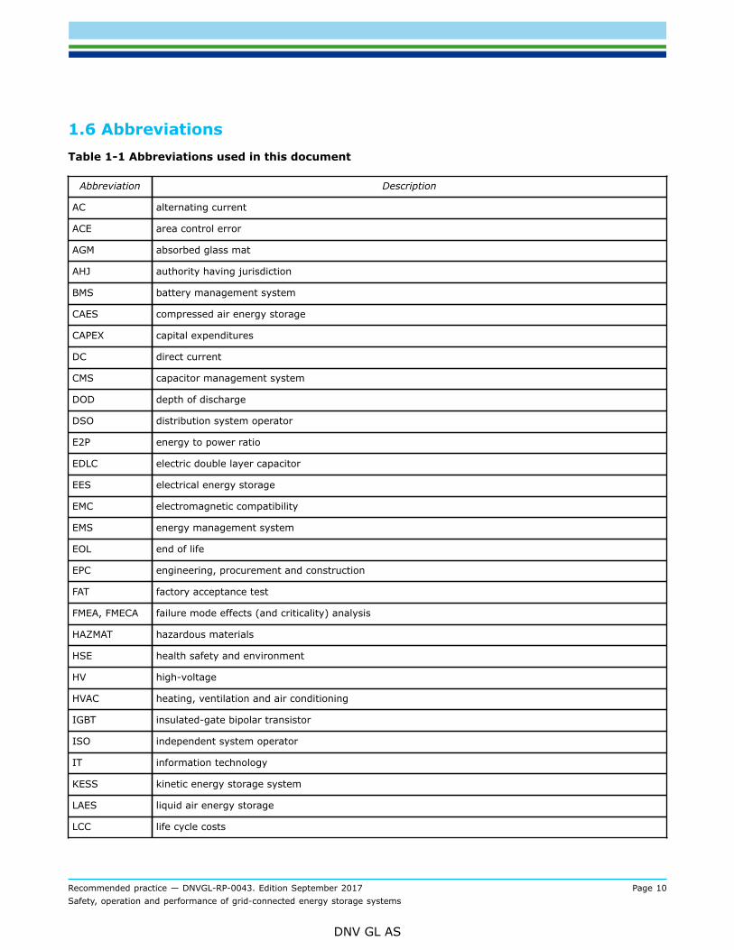
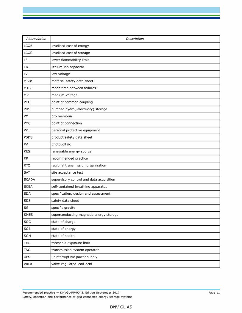
1.6 AbbreviationsTable 1-1 Abbreviations used in this document
Abbreviation Description
AC alternating current
ACE area control error
AGM absorbed glass mat
AHJ authority having jurisdiction
BMS battery management system
CAES compressed air energy storage
CAPEX capital expenditures
DC direct current
CMS capacitor management system
DOD depth of discharge
DSO distribution system operator
E2P energy to power ratio
EDLC electric double layer capacitor
EES electrical energy storage
EMC electromagnetic compatibility
EMS energy management system
EOL end of life
EPC engineering, procurement and construction
FAT factory acceptance test
FMEA, FMECA failure mode effects (and criticality) analysis
HAZMAT hazardous materials
HSE health safety and environment
HV high-voltage
HVAC heating, ventilation and air conditioning
IGBT insulated-gate bipolar transistor
ISO independent system operator
IT information technology
KESS kinetic energy storage system
LAES liquid air energy storage
LCC life cycle costs
Recommended practice — DNVGL-RP-0043. Edition September 2017 Page 11Safety, operation and performance of grid-connected energy storage systems
DNV GL AS
Abbreviation Description
LCOE levelised cost of energy
LCOS levelised cost of storage
LFL lower flammability limit
LIC lithium-ion capacitor
LV low-voltage
MSDS material safety data sheet
MTBF mean time between failures
MV medium-voltage
PCC point of common coupling
PHS pumped hydro(-electricity) storage
PM pro memoria
POC point of connection
PPE personal protective equipment
PSDS product safety data sheet
PV photovoltaic
RES renewable energy source
RP recommended practice
RTO regional transmission organization
SAT site acceptance test
SCADA supervisory control and data acquisition
SCBA self-contained breathing apparatus
SDA specification, design and assessment
SDS safety data sheet
SG specific gravity
SMES superconducting magnetic energy storage
SOC state of charge
SOE state of energy
SOH state of health
TEL threshold exposure limit
TSO transmission system operator
UPS uninterruptible power supply
VRLA valve-regulated lead-acid

Recommended practice — DNVGL-RP-0043. Edition September 2017 Page 12Safety, operation and performance of grid-connected energy storage systems
DNV GL AS
SECTION 2 ELECTRICAL ENERGY STORAGE SYSTEMS -INTRODUCTION AND DEFINITIONS
2.1 Definition of electrical energy storage system
2.1.1 Block diagram of systemAn electrical energy storage (EES) system reversibly converts energy into electrical energy, vice versa, andstores energy internally (see Table 2-5). An EES system consists of numerous components, all of which arevital to the operation of the system. Although minor differences exist between storage technologies, a blockdiagram similar to Figure 2-1 can be mapped to every EES system.The heart of the EES system is the energy storage device itself where the physical process of storingenergy takes place. In most practical applications, this process relies on an electrical (e.g. capacitors),electrochemical (e.g. batteries) or mechanical (e.g. flywheels) working principle. In many cases of grid-connected energy storage, a power converter between the electric power of the grid and the physical energystorage is required; this may be a single converter or a distributed conversion system. In other instances, amotor-generator is connected to the grid through a variable frequency drive or directly; in the latter case,the power converter is used to generate an excitation voltage or it is absent. Furthermore, a transformer isgenerally present between the grid and the EES system.The state of the physical energy storage is monitored and controlled by the system’s low-level controls,the storage management system, which in case of batteries (cell-based and redox flow) and capacitors isreferred to as battery management system (BMS) and capacitor management system (CMS), respectively. Itreads all relevant data from the physical storage; for example, in case of batteries or LICs voltages, currentsand temperatures, in case of flywheels rotating speed and temperatures, etcetera. Furthermore, it ensuresthat the system is working within its operating range and checks whether the electric power requested iswithin the operating range of the current system status.The high-level controls (energy management system, EMS) of the EES system determine its functionality.They determine when and at what rate the storage system shall be charged, idle or discharged. Dependingon the functionality of the system this can happen locally with minimal response times (milliseconds andbelow) based on locally measured data (e.g. current, voltage, power, frequency), or within an externalenergy management system, connected via a digital protocol (DNP3, modbus, etc.), which leads to slowerresponse times (seconds). When the system is set up for multifunctional performance a combination of localand external high-level controls is possible.

Recommended practice — DNVGL-RP-0043. Edition September 2017 Page 13Safety, operation and performance of grid-connected energy storage systems
DNV GL AS
Figure 2-1 Top-level block diagram of an EES system showing EES device, converter, auxiliariesand management systems1)
1)Based on: Schaede, Hendrik; Dezentrale elektrische Energiespeicherung mittels kinetischer Energiespeicherin Außenläufer-Bauform; Shaker, Aachen, Dissertation 2014Figure 2-1 is a functional drawing; certain components such as protection and safety components have notbeen drawn. Furthermore, a transformer may not be present, especially for smaller systems.Furthermore, several peripheral components (auxiliary equipment) are needed to run the system. Dependingon the physical working principle of the energy storage system these range from a cooling system (manystorage technologies) to liquid pumps (redox flow batteries) or vacuum pumps (flywheels). The low-levelcontrols monitor these peripherals.Consequently, the system boundaries of the energy storage system include all components needed to makethe system perform as required. This is especially important concerning the losses of the EES system (see[5.4] and [9.4.6]).A block diagram including sub-system drawings should be provided for each EES system.

Recommended practice — DNVGL-RP-0043. Edition September 2017 Page 14Safety, operation and performance of grid-connected energy storage systems
DNV GL AS
2.1.2 Electrical energy storage technologiesThere are five broad storage classes according to the form of energy inside the storage medium: electrical1,electrochemical, mechanical, chemical and thermal. There are technologies from each class already deployedin the grid and there are others at various stages of maturity. The technologies mainly applicable for grid-connected storage are shown in Figure 2-2. Short descriptions of the main technology classes for EESsystems are given below.Chemical storage and thermal storage are not considered in this RP. An example of chemical storage ishydrogen (e.g. in the electrolyser/hydrogen storage/fuel cell combination). Examples of thermal storage are(hot) water, ice, molten salt and ceramics.Within the electrochemical class, technologies are generally distinguished by the key chemical compound(s)in their active components. It should be noted that within each technology, many subtechnologies may exist,with widely differing properties. For example, lead acid batteries can be of the AGM, flooded, gel or leadcrystal types, with significant differences in performance, lifetime, safety, etc.
Figure 2-2 Main electrical energy storage technologies for the purpose of grid-connected storage
1 The storage class "Electrical", referring to the form of energy inside the storage medium, should not beconfused with the higher-level categorisation "Electrical energy storage", referring to the form of energygoing into and out of the system.
Recommended practice — DNVGL-RP-0043. Edition September 2017 Page 15Safety, operation and performance of grid-connected energy storage systems
DNV GL AS
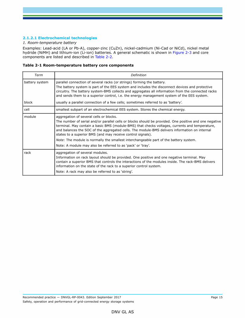
2.1.2.1 Electrochemical technologies1. Room-temperature batteryExamples: Lead-acid (LA or Pb-A), copper-zinc (CuZn), nickel-cadmium (Ni-Cad or NiCd), nickel metalhydride (NiMH) and lithium-ion (Li-ion) batteries. A general schematic is shown in Figure 2-3 and corecomponents are listed and described in Table 2-2.
Table 2-1 Room-temperature battery core components
Term Definition
battery system parallel connection of several racks (or strings) forming the battery.The battery system is part of the EES system and includes the disconnect devices and protectivecircuitry. The battery system-BMS collects and aggregates all information from the connected racksand sends them to a superior control, i.e. the energy management system of the EES system.
block usually a parallel connection of a few cells; sometimes referred to as ‘battery’.
cell smallest subpart of an electrochemical EES system. Stores the chemical energy.
module aggregation of several cells or blocks.The number of serial and/or parallel cells or blocks should be provided. One positive and one negativeterminal. May contain a basic BMS (module-BMS) that checks voltages, currents and temperature,and balances the SOC of the aggregated cells. The module-BMS delivers information on internalstates to a superior BMS (and may receive control signals).
Note: The module is normally the smallest interchangeable part of the battery system.
Note: A module may also be referred to as ‘pack’ or ‘tray’.
rack aggregation of several modules.Information on rack layout should be provided. One positive and one negative terminal. Maycontain a superior BMS that controls the interactions of the modules inside. The rack-BMS deliversinformation on the state of the rack to a superior control system.
Note: A rack may also be referred to as ‘string’.

Recommended practice — DNVGL-RP-0043. Edition September 2017 Page 16Safety, operation and performance of grid-connected energy storage systems
DNV GL AS
Figure 2-3 General schematic and components of a cell-based battery EES system
The subdivision mentioned in Table 2-2 and Figure 2-3 (block, module, …) may differ according to technology.Some technologies may also have other differences from this figure, e.g. the modularity of the BMS or thepresence of the transformer. Furthermore, the converter in Figure 2-3 may be a single converter connectedto the battery system or a distributed conversion system with converters connected directly to racks orstrings.2. High-temperature batteryExamples: NaS and NaNiCl batteries. The general schematic (Figure 2-3) and core components (Table 2-2)for room-temperature battery also apply to high-temperature batteries.3. Redox flow batteryExamples: all-vanadium (VRFB) and zinc-bromine (Zn-Br) redox flow batteries. A general schematic is shownin Figure 2-4 and core components are listed and described in Table 2-3.
Table 2-2 Redox flow battery core components
Term Definition
cell smallest subpart of an electrochemical EES system, where chemical energy is converted into electrical energy.
stack series connection of redox flow cells. In general, the electrical connections in a stack are in series and theliquid flows are in parallel.
Recommended practice — DNVGL-RP-0043. Edition September 2017 Page 17Safety, operation and performance of grid-connected energy storage systems
DNV GL AS
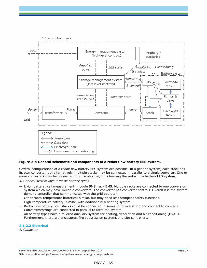
Figure 2-4 General schematic and components of a redox flow battery EES system.
Several configurations of a redox flow battery EES system are possible. In a generic system, each stack hasits own converter, but alternatively, multiple stacks may be connected in parallel to a single converter. One ormore converters may be connected to a transformer, thus forming the redox flow battery EES system.4. General system layout for all battery types
— Li-ion battery: cell measurement, module BMS, rack BMS. Multiple racks are connected to one conversionsystem which may have multiple converters. The converter has converter controls. Overall it is the systemdemand controller that communicates with the grid operator.
— Other room-temperature batteries: similar, but may need less stringent safety functions.— High-temperature battery: similar, with additionally a heating system.— Redox flow battery: cell stacks could be connected in series to form a string and connect to converter.
Converters/strings are connected in parallel to form the system.— All battery types have a tailored auxiliary system for heating, ventilation and air conditioning (HVAC).
Furthermore, there are enclosures, fire suppression systems and site controllers.
2.1.2.2 Electrical1. Capacitor

Recommended practice — DNVGL-RP-0043. Edition September 2017 Page 18Safety, operation and performance of grid-connected energy storage systems
DNV GL AS
Capacitors store electrical energy in the electric field between a positively and a negatively charged plate.The two plates are parallel and separated by an insulator, the dielectric. When accumulating energy, theelectric charges on the plates build up. Power generation corresponds to discharging the plates.The basic electrostatic capacitor has limited properties concerning power and energy density, nominal powerand nominal voltage. For application in grid-connected energy storage supercapacitors are widespread(the terms ultracapacitor and supercapacitor are treated as synonyms in this document). These can besubdivided into two types: an electric double-layer capacitor (EDLC) stores the charge electrostatically,a pseudocapacitor stores the charge electrochemically, i.e. similar to a battery. A hybrid capacitor is acombination of the two. The Li-ion capacitor (LIC) is a hybrid capacitor: one electrode is similar to theelectrode of an electrostatic capacitor, the other electrode is similar to the electrode (i.e. the anode) of a Li-ion battery.
Note: the terms ultracapacitor and supercapacitor are synonyms.Note: An EDLC stores the charge electrostatically; a pseudocapacitor stores the charge electrochemically; ahybrid capacitor is a combination of the two above.
Figure 2-5 Classification of supercapacitors
System layout: cell measurement, module CMS, module (or pack) CMS; multiple modules (or packs) in arack (or string) are connected to one conversion system (may have multiple converters); converter hasconverter controls; overall is the system demand controller that communicates with the grid operator. Table2-2 and Figure 2-3 (see [2.1.2.1]) also apply to supercapacitors. Generally, what is called BMS in a batterysystem is called a CMS (cell or capacitor management system) in a supercapacitor system.2. Superconducting magnetic energy storageSuperconducting magnetic energy storages (SMES) stores electrical energy in a magnetic field arounda superconducting coil. Superconducting properties of the coil wire, resulting in a permanent flow ofdirect current without losses, are used to maintain the magnetic field. Cryogenic cooling of the coil below100 Kelvin is required to maintain the superconducting state. Also, a protection system is needed to protectthe magnet from local overheating, thereby losing its superconducting state (quench protection). The coolingsystem translates into self-discharge of the storage system. SMES is still in the R&D phase, mainly becauseof the superconducting wire technology. Several demonstrations have been deployed of up to 10 MW. The
Recommended practice — DNVGL-RP-0043. Edition September 2017 Page 19Safety, operation and performance of grid-connected energy storage systems
DNV GL AS
technology is expected to be ideal for maintaining power quality due to its fast response time and highpower-to-energy ratio.SMES is not scope for this RP.
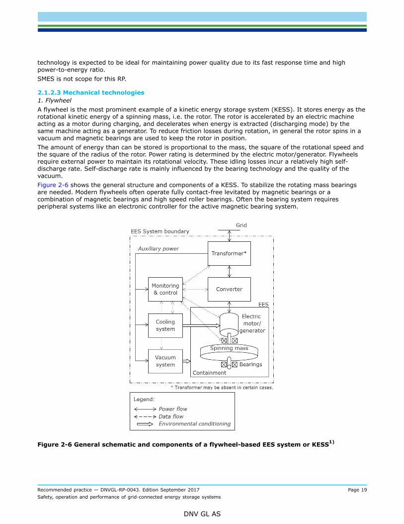
2.1.2.3 Mechanical technologies1. FlywheelA flywheel is the most prominent example of a kinetic energy storage system (KESS). It stores energy as therotational kinetic energy of a spinning mass, i.e. the rotor. The rotor is accelerated by an electric machineacting as a motor during charging, and decelerates when energy is extracted (discharging mode) by thesame machine acting as a generator. To reduce friction losses during rotation, in general the rotor spins in avacuum and magnetic bearings are used to keep the rotor in position.The amount of energy than can be stored is proportional to the mass, the square of the rotational speed andthe square of the radius of the rotor. Power rating is determined by the electric motor/generator. Flywheelsrequire external power to maintain its rotational velocity. These idling losses incur a relatively high self-discharge rate. Self-discharge rate is mainly influenced by the bearing technology and the quality of thevacuum.Figure 2-6 shows the general structure and components of a KESS. To stabilize the rotating mass bearingsare needed. Modern flywheels often operate fully contact-free levitated by magnetic bearings or acombination of magnetic bearings and high speed roller bearings. Often the bearing system requiresperipheral systems like an electronic controller for the active magnetic bearing system.
Figure 2-6 General schematic and components of a flywheel-based EES system or KESS1)

Recommended practice — DNVGL-RP-0043. Edition September 2017 Page 20Safety, operation and performance of grid-connected energy storage systems
DNV GL AS
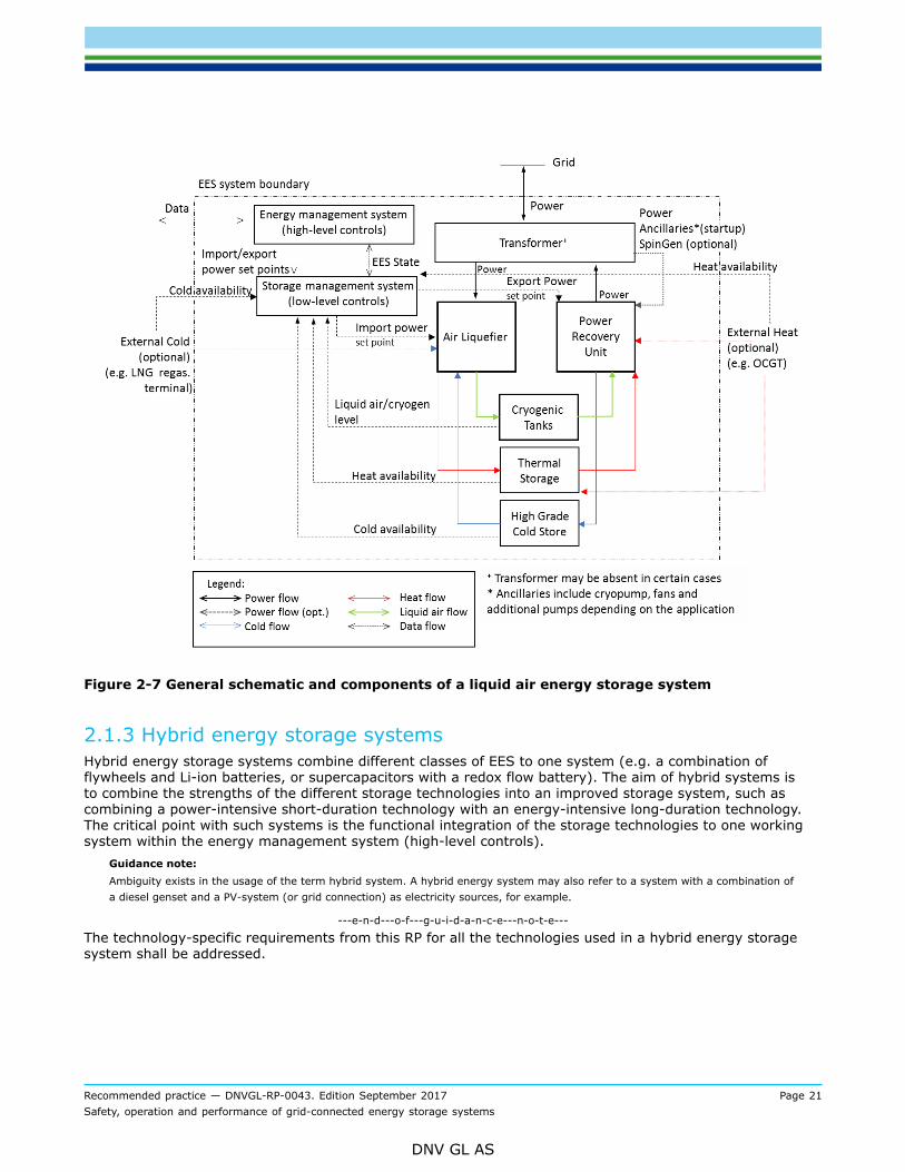
1)Based on: Schaede, Hendrik; Dezentrale elektrische Energiespeicherung mittels kinetischer Energiespeicherin Außenläufer-Bauform; Shaker, Aachen, Dissertation 2014Figure 2-6 is a functional drawing, showing EES device, converter, auxiliaries and control systems. Certaincomponents such as protection and safety components have not been drawn. Further, a transformer may notbe present.An electric machine converts the electrical energy to the mechanic energy. A converter and transformercouple the motor/generator to the grid. The high power density of most motor/generators requires a coolingsystem.The flywheel-mass rotates under low pressure (often vacuum or even high vacuum) in a containment toreduce friction losses. On the one hand the containment acts as the low-pressure vessel, on the other hand itacts as a safety measure in case of a disintegration of the flywheel (see Sec.7).System layout: each flywheel has its own converter; multiple converters in a flywheel-based ESS system maybe connected to one transformer.2. Pumped hydro storagePumped hydro storage (PHS) involves the pumping of water from a lower basin into a higher one. Whenpower is delivered (discharging mode), the water is run through water turbines in identical fashion to anormal hydropower plant, generating power. In charging mode, the turbines are used as pumps. Maximumpower generation is determined by the maximum flow of water from the upper to the lower storage reservoirand the height difference between the two reservoirs (i.e. the head), if the generators and turbines aresized accordingly. The amount of electricity that can be stored is determined by the size of the (smallest)reservoirs. The cycle efficiency of a PHS is around 70-85%, the losses are incurred through the losses inpumping, generation and water evaporation.System layout: multiple turbines on one connecting rail; one upper and one lower reservoir; low-level controlper turbine; 1 high-level controlPHS is out of scope of this RP.3. Compressed air energy storageCompressed air energy storage (CAES) stores electricity by compressing air into a reservoir and generateselectricity by expanding the compressed air in a gas turbine. The compression is performed by a compressorunit. Depending on the type of CAES, the heat produced during the compression is stored or released intothe atmosphere. The compressed air is stored in a suitable geological formation such as salt domes, aquifersor depleted gas fields. The air is released for power generation: it is heated by combustion of natural gas andthen expanded in the gas turbine.The generation capacity of the CAES is determined by the size of the gas turbines. The compressor and thegas turbines can be dimensioned independently. The size of the geological formation determines the amountof energy that can be stored.System layout: one turbine/compressor with compressed air storage system4. Liquid air energy storageLiquid air energy storage (LAES) stores electricity by liquefying air into tanks and generates electricity byexpanding the liquefied air in a turbine (Figure 2-7). Air turns to liquid when refrigerated to -196°C, andcan be stored in standard insulated vessels, either unpressurised or pressurized. Exposure to ambienttemperatures above the boiling point of liquid air causes re-gasification and an expansion in volume, whichis used to drive a turbine and create electricity. The charging, energy store and power recovery parts of thesystem can be scaled independently. An optimised LAES also includes a heat and/or cold storage system. ALAES system can be integrated with external sources of (waste) heat and/or cold. The system does not havegeographical constraints.The main components of the system layout are (Figure 2-6): one or more air liquefiers; one or more liquidair (cryogenic) storage tanks and heat storage and cold storage; one or more expansion turbines/generators(i.e. power recovery units).
Recommended practice — DNVGL-RP-0043. Edition September 2017 Page 21Safety, operation and performance of grid-connected energy storage systems
DNV GL AS
Figure 2-7 General schematic and components of a liquid air energy storage system
2.1.3 Hybrid energy storage systemsHybrid energy storage systems combine different classes of EES to one system (e.g. a combination offlywheels and Li-ion batteries, or supercapacitors with a redox flow battery). The aim of hybrid systems isto combine the strengths of the different storage technologies into an improved storage system, such ascombining a power-intensive short-duration technology with an energy-intensive long-duration technology.The critical point with such systems is the functional integration of the storage technologies to one workingsystem within the energy management system (high-level controls).
Guidance note:Ambiguity exists in the usage of the term hybrid system. A hybrid energy system may also refer to a system with a combination ofa diesel genset and a PV-system (or grid connection) as electricity sources, for example.
---e-n-d---o-f---g-u-i-d-a-n-c-e---n-o-t-e---
The technology-specific requirements from this RP for all the technologies used in a hybrid energy storagesystem shall be addressed.

Recommended practice — DNVGL-RP-0043. Edition September 2017 Page 22Safety, operation and performance of grid-connected energy storage systems
DNV GL AS
2.1.4 Monitoring and control systemEach EES system needs a monitoring and control system. There are two basic types of functions for thissystem:
— safety management functions (e.g. monitor the values of temperature, voltage and current and takecorrective actions (e.g. decrease power) or emergency actions (e.g. switch off) if one or more of theseparameters get out of the safety limits)
— operational management functions (e.g. monitor the values of power, SOC, current and voltage andcontrol the system in such a way that the desired values over time are realised).
For optimal system safety, the safety management functions should be embedded at different levels of theEES system (e.g. monitor string current and system current; monitor cell voltage and module voltage). Formore information see Sec.7.For optimal operational behaviour of the system, the operational management functions should beincorporated at different levels of the EES system. For example: the EMS of the EES system will communicatewith the grid operator’s system about the desired output power profile of the EES system at the POC; theEMS will communicate this internally with the energy storage management system, and the latter mighttranslate this and communicate it at a lower control level to parts of the EES.
Guidance note:In case of a Li-ion battery and a supercapacitor storage system, each individual cell voltage should be monitored for safety andoperational reasons. In case of paralleled cells, each group of paralleled cells may be monitored as if it were a single cell. Themodule-BMS, respectively the CMS for supercapacitor systems, will perform the safety checks on cell and module level and itwill transfer the aggregated data (e.g. module voltage and current) to the BMS/CMS that resides one level up. In a complicatedbattery storage system, there may be a module-BMS/CMS, rack-BMS/CMS and system-BMS/CMS, complemented by a convertermanagement system and the EMS at the highest control level.
---e-n-d---o-f---g-u-i-d-a-n-c-e---n-o-t-e---
2.2 Definitions of other terms
2.2.1 Roles concerning electrical energy storage systemsThe roles and relationships contained in Table 2-4 are for general guidance. A party can have more than onerole simultaneously, e.g. an aggregator who may both own and operate an EES system. The actual division ofresponsibilities should be outlined in detail within the contract terms.
Table 2-3 Roles concerning EES systems
Term Definition
customer the end user of electrical energy and the user of a grid connection, who is a customer of thegrid operator
DSO** the distribution system operator is responsible for the distribution of electrical power at lowand medium voltage level and for (local) power distribution system operation within a certainarea
EES system integrator the system integrator provides/sells the EES system to the owner and is responsible for fullEES system functionality
EES system operator the operator is responsible for the operation of the grid-connected EES system; the operatormanages the EES system side of the POC
EES system owner the legal owner of the grid-connected EES system

Recommended practice — DNVGL-RP-0043. Edition September 2017 Page 23Safety, operation and performance of grid-connected energy storage systems
DNV GL AS
Term Definition
EES system user the user realizes the benefits of the EES system; the user typically receives services from theoperator
EPC contractor engineering, procurement and construction (EPC) firm responsible for the site layout,preparation and usually the installation of the EES system equipment
grid operator the operator of the grid can be either the TSO, ISO or DSO and manages the grid-side of thePOC
ISO* the independent system operator is responsible for the transmission of electrical power athigh voltage level and for power system operation within a certain area
manufacturer the manufacturer of a subset of the different EES system components, responsible for safetyand functional aspects of his products
supplier the vendor of the EES system; either the EES system integrator or the EPC contractor
TSO* the transmission system operator is responsible for the transmission of electrical power athigh voltage level and for power system operation within a certain area
* In certain regions, the term TSO (and DSO) is used, whereas in others, ISO is used (e.g. Europe and the USA,respectively).** The distribution network operator (DNO) is responsible for the distribution of electrical power at low and mediumvoltage level and for (local) network operation within a certain area. The DNO formally has fewer system operationresponsibilities than a DSO. Within the scope of this RP, no distinction between DNO and DSO has been made. Whereapplicable, the term DSO can be replaced by DNO.
2.2.2 Terms and definitions for electrical energy storage systemclassificationTable 2-4 Terms and definitions for EES system classification
Term Definition Reference
EES system installation or multiple installations, comprising at least oneEES, whose purpose is to receive (charge) electrical energyas a grid-connected system, store this energy internally insome manner, and discharge electrical energy as a grid-connected system, and which includes civil engineeringworks, energy conversion equipment and all the necessaryauxiliary equipment. The EES system is coordinated toprovide services to the grid.
IEC 62933-1 CDV1) (Mar 2016)
electrical energy storage(EES)
installation that reversibly converts energy into electricalenergy, vice versa, and stores energy internallyNote 1 to entry: EES may also be used to indicate theactivity of an apparatus described in the definition, i.e. whileperforming its functionality.
IEC 62933-1 CDV
grid-connected to be connected to a public grid with one or more POCs IEC 62933-1 CDV
Recommended practice — DNVGL-RP-0043. Edition September 2017 Page 24Safety, operation and performance of grid-connected energy storage systems
DNV GL AS
Term Definition Reference
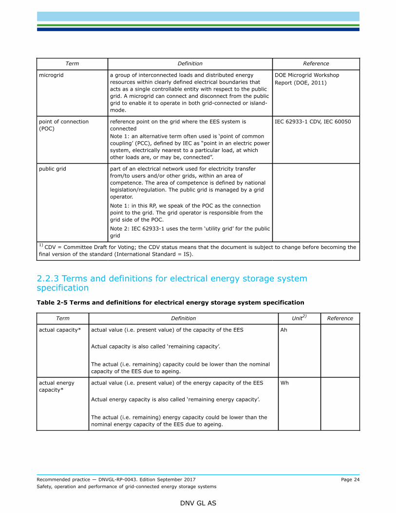
microgrid a group of interconnected loads and distributed energyresources within clearly defined electrical boundaries thatacts as a single controllable entity with respect to the publicgrid. A microgrid can connect and disconnect from the publicgrid to enable it to operate in both grid-connected or island-mode.
DOE Microgrid WorkshopReport (DOE, 2011)
point of connection(POC)
reference point on the grid where the EES system isconnectedNote 1: an alternative term often used is ‘point of commoncoupling’ (PCC), defined by IEC as “point in an electric powersystem, electrically nearest to a particular load, at whichother loads are, or may be, connected”.
IEC 62933-1 CDV, IEC 60050
public grid part of an electrical network used for electricity transferfrom/to users and/or other grids, within an area ofcompetence. The area of competence is defined by nationallegislation/regulation. The public grid is managed by a gridoperator.
Note 1: in this RP, we speak of the POC as the connectionpoint to the grid. The grid operator is responsible from thegrid side of the POC.
Note 2: IEC 62933-1 uses the term ‘utility grid’ for the publicgrid
1) CDV = Committee Draft for Voting; the CDV status means that the document is subject to change before becoming thefinal version of the standard (International Standard = IS).
2.2.3 Terms and definitions for electrical energy storage systemspecificationTable 2-5 Terms and definitions for electrical energy storage system specification
Term Definition Unit2) Reference
actual capacity* actual value (i.e. present value) of the capacity of the EES
Actual capacity is also called ‘remaining capacity’.
The actual (i.e. remaining) capacity could be lower than the nominalcapacity of the EES due to ageing.
Ah
actual energycapacity*
actual value (i.e. present value) of the energy capacity of the EES
Actual energy capacity is also called ‘remaining energy capacity’.
The actual (i.e. remaining) energy capacity could be lower than thenominal energy capacity of the EES due to ageing.
Wh

Recommended practice — DNVGL-RP-0043. Edition September 2017 Page 25Safety, operation and performance of grid-connected energy storage systems
DNV GL AS
Term Definition Unit2) Reference
C-rate rate at which a battery EES is charged/discharged. A C-rate of ‘xC’means that the battery (dis)charging current Ib (with unit A) equals:
Ib = x It,
with It = (nominal capacity) / (1 h),
with nominal capacity given in Ah.
A C-rate of ‘C/y’ is equal to a C-rate of 1/y C.
In IEC the charging rate is defined as a multiple of It (IEV 482-05-45).
IEC TC120 does not use the term C-rate, but rather the EES systempower, which may be compared relative to the energy capacity of theEES to calculate charging/discharging times.
C (**) (**) This isnot an SIunit.
calendar lifetime* theoretically expected lifetime if the EES is not cycled at all, caused byEES degradation over time
years [5.5.1]
capacity* amount of electric charge a fully charged battery EES can deliver at aspecified discharge current (or discharge current profile), at specifiedenvironmental conditions, between its full state and its empty state
The full and empty state of the battery EES may be specified byphysical or electrical boundary conditions, such as the minimum andmaximum operating voltage of the battery system.
Capacity is a typical metric for electrochemical batteries. EEStechnologies other than batteries normally use energy capacityinstead of capacity as a measure for energy storage capability.
Ah
cycle charge/discharge cycle consisting of four controlled phases startingfrom an initial SOC, in particular, either: a charge phase, thena pause, then a discharge phase and finally a new pause; or: adischarge phase, then a pause, then a charge phase and finally a newpause
The patterns of the charge and discharge phases are generally linear(constant active power); however different patterns can be defined.
A pause means zero active power into and out of the EES.
1 IEC 62933-1CDV
cycle lifetime* theoretically achievable number of cycles when the EES is cycled withequal full charge-discharge cycles 1 [5.5.2]
depth ofdischarge
energy discharged from the EES during a cycle (discharge phase)expressed as a percentage of the nominal energy capacity
%
EES systemefficiency*
useful energy output at the POC divided by the energy inputs to theEES system including all parasitic energies needed to run the system,such as heating or cooling, etc. and expressed as percentage, atspecified service conditions
% IEC 62933-1CDV

Recommended practice — DNVGL-RP-0043. Edition September 2017 Page 26Safety, operation and performance of grid-connected energy storage systems
DNV GL AS
Term Definition Unit2) Reference
efficiency* energy delivered by the EES divided by energy received by the EES,presented as a percentage
Efficiency may be defined at different levels of the system:
— related to the EES behind the converter— related to the EES system at the POC including auxiliary power
demand— related to the EES system at the POC without taking the auxiliary
power demand into account.
The efficiency may depend on the charging and/or dischargingpower, the initial and final SOC, the pauses between charging anddischarging, and the operating conditions (temperature, humidity, airpressure).
Efficiency should either be defined for a number (> 1) of equal pre-defined cycles or for a certain pre-defined application duty-cycleprofile.
Efficiency related to power parameters is out of scope of this RP.
% [5.4]
efficiency map* graphical overview of the EES system efficiency for all relevant systemstates, defined by charging and discharging power and the initial andfinal state of charge
% [5.4.1]
end of life moment in time after commissioning of the EES system when itsperformance, whether technical, financial or otherwise, has degradedto the point of being no longer usable in its current application
End of life may be reached before the expected lifetime because ofadditional criteria beyond technical calendar life and cycle life.
(notapplicable)
[4.9] and[6.5.3]
energy capacity* amount of electrical energy a fully charged EES can deliver at aspecified discharge power (or discharge power profile), at specifiedenvironmental conditions, between its full state and empty state
The full and empty state of the EES may be specified by physical orelectrical boundary conditions, such as the minimum and maximumoperating speed of a flywheel or the minimum and maximumoperating voltage of a battery or capacitor system.
Wh
expectedlifetime*
technical design duration for which the EES system performancecharacteristics are valid at nominal operation
Expected lifetime is strongly related to calendar lifetime and cyclelifetime
years [5.5.1] and[5.5.2]
full cycle nominal cycle, with a charging phase at maximum continuouscharging power (and typical charging profile) from 0% SOC to 100%SOC and a discharging phase at maximum continuous dischargingpower (and typical discharging profile) from 100% SOC to 0% SOC
1

Recommended practice — DNVGL-RP-0043. Edition September 2017 Page 27Safety, operation and performance of grid-connected energy storage systems
DNV GL AS
Term Definition Unit2) Reference
initial delay time an EES system requires from a trigger to provide power (such asa command or a grid event) until it starts to ramp up power
This time is called ‘dead time’ in IEC 62933-1 CDV.
ms [5.3.3]
maximumcontinuouspower*
maximum value of the active power the ESS system is designed for incontinuous operation, i.e. in constant charging mode until a specifichigh SOC is reached or in constant discharging mode until a specificlow SOC is reached
Maximum continuous charge power and maximum continuousdischarge power may have different values.
kW [5.1.1]
maximum peakpower*
maximum value of the active power at which the ESS system is ableto operate during a short period of time and during a specific SOCwindow; this period of time and the specific SOC window shall bespecified together with the maximum peak power
Maximum peak charge power and maximum peak discharge powermay have different values.
kW [5.1.2]
nominal capacity initial value of the capacity of the EES as stated by the manufacturerand by which the EES is designated and identified
Ah IEC 62933-1CDV
nominal cycle pre-defined charge/discharge cycle used in the characterization,specification and testing of the EES system
A typical nominal cycle will show the same SOC before and after thecycle, have relatively short pauses and have constant charging anddischarging power equal to the nominal charging and dischargingpower, respectively. Also, its DOD will be (close to) the maximum DODallowed.
A variation on the nominal cycle may be a cycle with power levelsequal to the nominal cycle, but a different initial SOC and/or adifferent SOC at the first pause. Another variation on the nominalcycle may be a cycle with SOC values at the start and at the pausesequal to the nominal cycle, but different charge and discharge powerlevels.
IEC 62933-1 CDV uses the term ‘standard charging/discharging cycle’
1
nominal energycapacity*
initial value of the energy capacity of the EES as stated by themanufacturer and by which the EES is designated and identified
kWh IEC 62933-1CDV
nominalfrequency
value of the frequency by which the POC is designed and identified
The nominal frequency can also be a range of values at the POCwhere the EES system is able to remain connected to the grid andperform all its duties without risk of damage.
Hz IEC 62933-1CDV
nominal operation EES operation at nominal voltage and frequency, rated charging anddischarging power and normal environmental conditions
(notapplicable)
Recommended practice — DNVGL-RP-0043. Edition September 2017 Page 28Safety, operation and performance of grid-connected energy storage systems
DNV GL AS
Term Definition Unit2) Reference
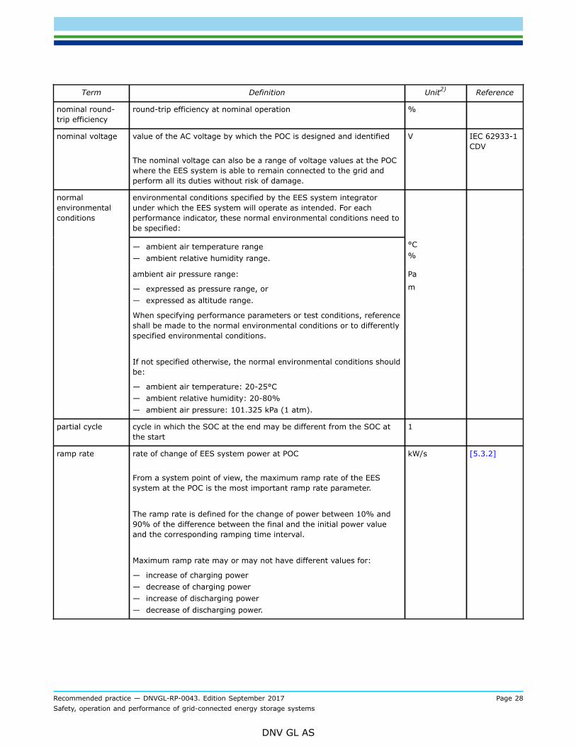
nominal round-trip efficiency
round-trip efficiency at nominal operation %
nominal voltage value of the AC voltage by which the POC is designed and identified
The nominal voltage can also be a range of voltage values at the POCwhere the EES system is able to remain connected to the grid andperform all its duties without risk of damage.
V IEC 62933-1CDV
environmental conditions specified by the EES system integratorunder which the EES system will operate as intended. For eachperformance indicator, these normal environmental conditions need tobe specified:
— ambient air temperature range— ambient relative humidity range.
°C%
normalenvironmentalconditions
ambient air pressure range:
— expressed as pressure range, or— expressed as altitude range.
When specifying performance parameters or test conditions, referenceshall be made to the normal environmental conditions or to differentlyspecified environmental conditions.
If not specified otherwise, the normal environmental conditions shouldbe:
— ambient air temperature: 20-25°C— ambient relative humidity: 20-80%— ambient air pressure: 101.325 kPa (1 atm).
Pa
m
partial cycle cycle in which the SOC at the end may be different from the SOC atthe start
1
ramp rate rate of change of EES system power at POC
From a system point of view, the maximum ramp rate of the EESsystem at the POC is the most important ramp rate parameter.
The ramp rate is defined for the change of power between 10% and90% of the difference between the final and the initial power valueand the corresponding ramping time interval.
Maximum ramp rate may or may not have different values for:
— increase of charging power— decrease of charging power— increase of discharging power— decrease of discharging power.
kW/s [5.3.2]
Recommended practice — DNVGL-RP-0043. Edition September 2017 Page 29Safety, operation and performance of grid-connected energy storage systems
DNV GL AS
Term Definition Unit2) Reference
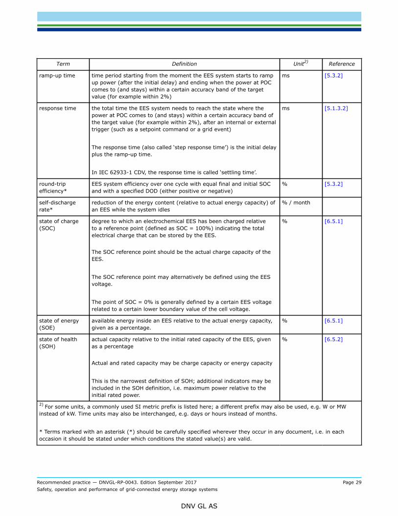
ramp-up time time period starting from the moment the EES system starts to rampup power (after the initial delay) and ending when the power at POCcomes to (and stays) within a certain accuracy band of the targetvalue (for example within 2%)
ms [5.3.2]
response time the total time the EES system needs to reach the state where thepower at POC comes to (and stays) within a certain accuracy band ofthe target value (for example within 2%), after an internal or externaltrigger (such as a setpoint command or a grid event)
The response time (also called ‘step response time’) is the initial delayplus the ramp-up time.
In IEC 62933-1 CDV, the response time is called ‘settling time’.
ms [5.1.3.2]
round-tripefficiency*
EES system efficiency over one cycle with equal final and initial SOCand with a specified DOD (either positive or negative)
% [5.3.2]
self-dischargerate*
reduction of the energy content (relative to actual energy capacity) ofan EES while the system idles
% / month
state of charge(SOC)
degree to which an electrochemical EES has been charged relativeto a reference point (defined as SOC = 100%) indicating the totalelectrical charge that can be stored by the EES.
The SOC reference point should be the actual charge capacity of theEES.
The SOC reference point may alternatively be defined using the EESvoltage.
The point of SOC = 0% is generally defined by a certain EES voltagerelated to a certain lower boundary value of the cell voltage.
% [6.5.1]
state of energy(SOE)
available energy inside an EES relative to the actual energy capacity,given as a percentage.
% [6.5.1]
state of health(SOH)
actual capacity relative to the initial rated capacity of the EES, givenas a percentage
Actual and rated capacity may be charge capacity or energy capacity
This is the narrowest definition of SOH; additional indicators may beincluded in the SOH definition, i.e. maximum power relative to theinitial rated power.
% [6.5.2]
2) For some units, a commonly used SI metric prefix is listed here; a different prefix may also be used, e.g. W or MWinstead of kW. Time units may also be interchanged, e.g. days or hours instead of months.
* Terms marked with an asterisk (*) should be carefully specified wherever they occur in any document, i.e. in eachoccasion it should be stated under which conditions the stated value(s) are valid.
Recommended practice — DNVGL-RP-0043. Edition September 2017 Page 30Safety, operation and performance of grid-connected energy storage systems
DNV GL AS
SECTION 3 APPLICATIONS OF STATIONARY ELECTRICAL ENERGYSTORAGE SYSTEMS
3.1 GeneralThe aim of this section is to provide self-contained and concise descriptions of EES applications as appliedto the energy sector. The descriptions of storage applications provided in this section shall be used as areference for other sections of this RP.The current markets and technologies of EES are constantly evolving. It should thus be noted that the EESapplications listed in this section may not be exhaustive. New applications may arise, some applications maybecome unviable and/or specific applications may not be covered. In future updates of this document, suchdevelopments will be covered.
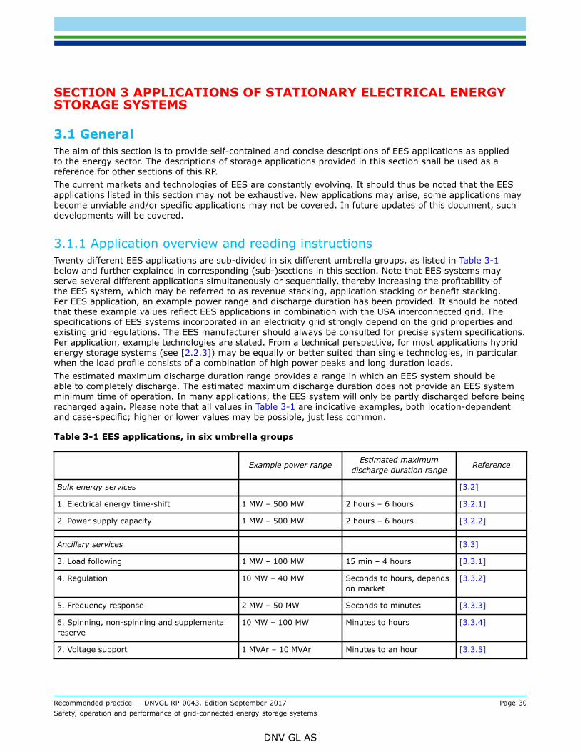
3.1.1 Application overview and reading instructionsTwenty different EES applications are sub-divided in six different umbrella groups, as listed in Table 3-1below and further explained in corresponding (sub-)sections in this section. Note that EES systems mayserve several different applications simultaneously or sequentially, thereby increasing the profitability ofthe EES system, which may be referred to as revenue stacking, application stacking or benefit stacking.Per EES application, an example power range and discharge duration has been provided. It should be notedthat these example values reflect EES applications in combination with the USA interconnected grid. Thespecifications of EES systems incorporated in an electricity grid strongly depend on the grid properties andexisting grid regulations. The EES manufacturer should always be consulted for precise system specifications.Per application, example technologies are stated. From a technical perspective, for most applications hybridenergy storage systems (see [2.2.3]) may be equally or better suited than single technologies, in particularwhen the load profile consists of a combination of high power peaks and long duration loads.The estimated maximum discharge duration range provides a range in which an EES system should beable to completely discharge. The estimated maximum discharge duration does not provide an EES systemminimum time of operation. In many applications, the EES system will only be partly discharged before beingrecharged again. Please note that all values in Table 3-1 are indicative examples, both location-dependentand case-specific; higher or lower values may be possible, just less common.
Table 3-1 EES applications, in six umbrella groups
Example power range Estimated maximumdischarge duration range Reference
Bulk energy services [3.2]
1. Electrical energy time-shift 1 MW – 500 MW 2 hours – 6 hours [3.2.1]
2. Power supply capacity 1 MW – 500 MW 2 hours – 6 hours [3.2.2]
Ancillary services [3.3]
3. Load following 1 MW – 100 MW 15 min – 4 hours [3.3.1]
4. Regulation 10 MW – 40 MW Seconds to hours, dependson market
[3.3.2]
5. Frequency response 2 MW – 50 MW Seconds to minutes [3.3.3]
6. Spinning, non-spinning and supplementalreserve
10 MW – 100 MW Minutes to hours [3.3.4]
7. Voltage support 1 MVAr – 10 MVAr Minutes to an hour [3.3.5]

Recommended practice — DNVGL-RP-0043. Edition September 2017 Page 31Safety, operation and performance of grid-connected energy storage systems
DNV GL AS
Example power range Estimated maximumdischarge duration range Reference
8. Black start 5 MW – 50 MW Seconds to hours [3.3.6]
Transmission infrastructure services [3.4]
9. Transmission congestion relief 1 MW – 100 MW 1 hour – 4 hours (cannotbe generalised easily)
[3.4.1]
10. Transmission upgrade deferral 10 MW – 100 MW 1 hour – 8 hours [3.4.2]
Distribution infrastructure services [3.5]
11. Distribution upgrade deferral 500 kW – 10 MW 1 hour – 4 hours [3.5.1]
Customer energy management and microgridservices
[3.6]
12. Power quality 100 kW – 10 MW Milliseconds – 15 minutes [3.6.1]
13. Power reliability (grid-connected) 50 kW – 10 MW 1 hour – 8 hours [3.6.2]
14. Power reliability (microgrid operation) 50 kW – 10 MW 1 hour – 8 hours [3.6.3]
15. Retail electrical energy time-shift 1 kW – 1 MW 1 hour – 6 hours [3.6.4]
16. Demand charge management 50 kW – 10 MW 15 minutes– 4 hours [3.6.5]
17. Renewable power consumptionmaximisation
50 kW – 10 MW 1 hour – 4 hours [3.6.6]
Renewables integration [3.7]
18. Ramp rate control 1 MW – 500 MW 1 minute cyclic-repetitive –4 hours
[3.7.1]
19. Generation peak shaving 1 MW – 500 MW 1 hour – 4 hours [3.7.2]
20. Capacity firming 1 MW – 500 MW 1 hour – 4 hours [3.7.3]
3.1.2 ReferencesThe following documents were used in order to construct the content of this subsection:
— Sandia National Laboratories, DOE/EPRI 2013 Electricity Storage Handbook in Collaboration with NRECA,USA, Jul 2013
— Sandia National Laboratories, Energy Storage for the Electricity Grid: Benefits and Market PotentialAssessment Guide
— Ecofys, Energy Storage Opportunities & Challenges – A West Coast Perspective White Paper— Energy Storage Operating Forum, A Good Practice Guide on Electrical Energy Storage, EA Technology,
United Kingdom, Dec 2014— Luo X., et al., Overview of current development in electrical energy storage technologies and the
application potential in power system operation, Applied Energy 137, 2015, p511-536— European Association for the Storage of Energy (EASE) and European Energy Research Alliance (EERA);
Joint EASE/EERA recommendations for a European Energy Storage Technology Development Roadmaptowards 2030
Recommended practice — DNVGL-RP-0043. Edition September 2017 Page 32Safety, operation and performance of grid-connected energy storage systems
DNV GL AS
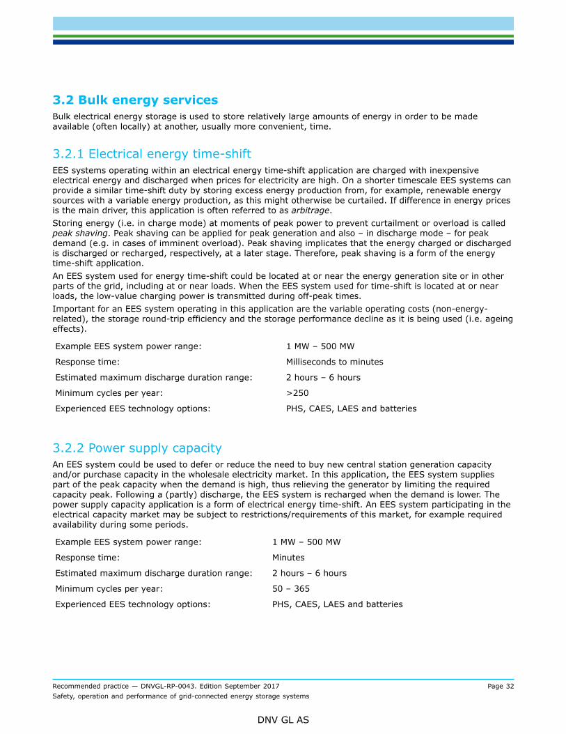
3.2 Bulk energy servicesBulk electrical energy storage is used to store relatively large amounts of energy in order to be madeavailable (often locally) at another, usually more convenient, time.
3.2.1 Electrical energy time-shiftEES systems operating within an electrical energy time-shift application are charged with inexpensiveelectrical energy and discharged when prices for electricity are high. On a shorter timescale EES systems canprovide a similar time-shift duty by storing excess energy production from, for example, renewable energysources with a variable energy production, as this might otherwise be curtailed. If difference in energy pricesis the main driver, this application is often referred to as arbitrage.Storing energy (i.e. in charge mode) at moments of peak power to prevent curtailment or overload is calledpeak shaving. Peak shaving can be applied for peak generation and also – in discharge mode – for peakdemand (e.g. in cases of imminent overload). Peak shaving implicates that the energy charged or dischargedis discharged or recharged, respectively, at a later stage. Therefore, peak shaving is a form of the energytime-shift application.An EES system used for energy time-shift could be located at or near the energy generation site or in otherparts of the grid, including at or near loads. When the EES system used for time-shift is located at or nearloads, the low-value charging power is transmitted during off-peak times.Important for an EES system operating in this application are the variable operating costs (non-energy-related), the storage round-trip efficiency and the storage performance decline as it is being used (i.e. ageingeffects).
Example EES system power range: 1 MW – 500 MW
Response time: Milliseconds to minutes
Estimated maximum discharge duration range: 2 hours – 6 hours
Minimum cycles per year: >250
Experienced EES technology options: PHS, CAES, LAES and batteries
3.2.2 Power supply capacityAn EES system could be used to defer or reduce the need to buy new central station generation capacityand/or purchase capacity in the wholesale electricity market. In this application, the EES system suppliespart of the peak capacity when the demand is high, thus relieving the generator by limiting the requiredcapacity peak. Following a (partly) discharge, the EES system is recharged when the demand is lower. Thepower supply capacity application is a form of electrical energy time-shift. An EES system participating in theelectrical capacity market may be subject to restrictions/requirements of this market, for example requiredavailability during some periods.
Example EES system power range: 1 MW – 500 MW
Response time: Minutes
Estimated maximum discharge duration range: 2 hours – 6 hours
Minimum cycles per year: 50 – 365
Experienced EES technology options: PHS, CAES, LAES and batteries
Recommended practice — DNVGL-RP-0043. Edition September 2017 Page 33Safety, operation and performance of grid-connected energy storage systems
DNV GL AS
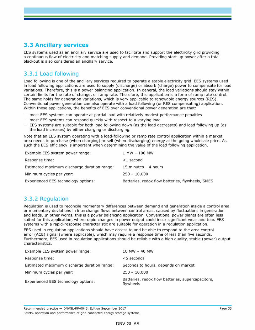
3.3 Ancillary servicesEES systems used as an ancillary service are used to facilitate and support the electricity grid providinga continuous flow of electricity and matching supply and demand. Providing start-up power after a totalblackout is also considered an ancillary service.
3.3.1 Load followingLoad following is one of the ancillary services required to operate a stable electricity grid. EES systems usedin load following applications are used to supply (discharge) or absorb (charge) power to compensate for loadvariations. Therefore, this is a power balancing application. In general, the load variations should stay withincertain limits for the rate of change, or ramp rate. Therefore, this application is a form of ramp rate control.The same holds for generation variations, which is very applicable to renewable energy sources (RES).Conventional power generation can also operate with a load following (or RES compensating) application.Within these applications, the benefits of EES over conventional power generation are that:
— most EES systems can operate at partial load with relatively modest performance penalties— most EES systems can respond quickly with respect to a varying load— EES systems are suitable for both load following down (as the load decreases) and load following up (as
the load increases) by either charging or discharging.
Note that an EES system operating with a load-following or ramp rate control application within a marketarea needs to purchase (when charging) or sell (when discharging) energy at the going wholesale price. Assuch the EES efficiency is important when determining the value of the load following application.
Example EES system power range: 1 MW – 100 MW
Response time: <1 second
Estimated maximum discharge duration range: 15 minutes – 4 hours
Minimum cycles per year: 250 – 10,000
Experienced EES technology options: Batteries, redox flow batteries, flywheels, SMES
3.3.2 RegulationRegulation is used to reconcile momentary differences between demand and generation inside a control areaor momentary deviations in interchange flows between control areas, caused by fluctuations in generationand loads. In other words, this is a power balancing application. Conventional power plants are often lesssuited for this application, where rapid changes in power output could incur significant wear and tear. EESsystems with a rapid-response characteristic are suitable for operation in a regulation application.EES used in regulation applications should have access to and be able to respond to the area controlerror (ACE) signal (where applicable), which may require a response time of less than five seconds.Furthermore, EES used in regulation applications should be reliable with a high quality, stable (power) outputcharacteristics.
Example EES system power range: 10 MW – 40 MW
Response time: <5 seconds
Estimated maximum discharge duration range: Seconds to hours, depends on market
Minimum cycles per year: 250 – 10,000
Experienced EES technology options: Batteries, redox flow batteries, supercapacitors,flywheels

Recommended practice — DNVGL-RP-0043. Edition September 2017 Page 34Safety, operation and performance of grid-connected energy storage systems
DNV GL AS
3.3.3 Frequency responseFrequency response is a general term for a component in the power system that responds to a change inthe grid frequency, with the purpose to counteract this change in frequency. A passive form of frequencyresponse is inertia that physically limits the rate of change of frequency. An active form of frequencyresponse is power/frequency control (or transmission system frequency control), performed by all largesynchronous generators, meaning that they dynamically increase (or decrease) their power when thefrequency decreases (or increases, respectively). See also[3.3.4].Inertia is needed in the power system to counteract grid frequency fluctuations, thereby stabilising thesystem. Causes of frequency fluctuations could be the loss of a generation unit or a transmission line(causing a sudden power imbalance). Various generator response actions are needed to counteract a suddenfrequency deviation, often within seconds. Physical inertia is provided by conventional power generators, i.e.synchronous generators.Synthetic inertia behaviour is the increase or decrease in power output proportional to the change of gridfrequency, thereby mimicking physical inertia, i.e. counteracting the grid frequency excursion. If the totalamount of physical inertia decreases in a power system, the amount of synthetic inertia should be increasedto maintain a certain minimum amount of total inertia for power system stability. Many grid-connectedrenewable energy sources do not provide additional synthetic inertia. Therefore, larger grid frequencydeviations may occur as the total inertia in the power system decreases. Keeping track of the total systeminertia could be a future task of TSOs or ISOs. Some TSOs in the USA and Europe (e.g. EirGrid and SONI inIreland) are procuring a new service called Synchronous Inertial Response (SIR), that is specifically meant toensure physical inertia in the power system.Electromechanical EES systems with a synchronous generator, like PHS, CAES and LAES, can provide physicalinertia, including SIR. Converter-connected EES systems can add synthetic inertia to the system.EES within a frequency response application could support the grid operator and thereby assure a smoothertransition from an upset period to normal operation. For a frequency response type of application the EESis required to provide support within milliseconds. Aside from this quick response, the frequency responseapplication is similar to load following (see [3.3.1]) and regulation (see [3.3.2]).
Example EES system power range: 2 MW – 50 MW
Response time: Milliseconds – 0.1 second
Estimated maximum discharge duration range: seconds to minutes
Minimum cycles per year: PM (application results in micro-cycles)
Experienced EES technology options: Batteries, flywheels, supercapacitors
3.3.4 Operating reservesA certain reserve capacity is usually available when operating an electric power system. This reserve capacitycan be called upon in case of a significant frequency disturbance, for example upon unexpected unavailabilityof generation capacity, thus ensuring system operation and availability. Subdivisions can be made based onhow quickly a reserve capacity is available. In the US for example, the following division is made:
— Spinning reserve is reserve generation capacity connected and synchronised with the grid and canrespond to compensate for generation or transmission outages. In remote grids spinning reserve ismainly present to cover for volatile consumption. In case a reserve is used to maintain system frequency,the reserve should be able to respond quickly. Spinning reserves are the first type of backup that isused when a power shortage occurs. Spinning reserve may be provided by all synchronous generators,including PHS, CAES and LAES systems with a synchronous generator.
— Non-spinning reserve is connected but not synchronised with the grid and usually available within 10minutes. Examples are offline generation capacity or a block of interruptible loads.

Recommended practice — DNVGL-RP-0043. Edition September 2017 Page 35Safety, operation and performance of grid-connected energy storage systems
DNV GL AS
— Supplemental reserve is available within one hour and is usually a backup for spinning and non-spinningreserves. Supplemental reserves are used after all spinning reserves are online.
In Europe, the following categorisation applies:2
— Frequency Containment Reserve (FCR) stabilizes the frequency after the disturbance at a steady-statevalue
— Frequency Restoration Reserve (FRR) controls the frequency towards its setpoint value by activation ofFRR and replaces the activated FCR. FRR can be automatic or manual (aFRR resp. mFRR).
— Reserve Replacement (RR) replaces the activated FRR (and in some countries FCR as well) and/orsupports the FRR activation by activation of RR.
The need for reserve generating capacity is signaled in the power system by the frequency deviating from itsnominal value. Therefore, reserves are linked to frequency response.Stored energy reserves are usually charged EES backup systems that have to be available for discharge whenrequired to ensure grid stability. PHS, CAES and LAES can act as operating reserves. Another example of anoperating reserve is an uninterruptible power supply (UPS) system, generally containing one or more EESsystems, which can provide near to instantaneous power in the event of a power interruption or a protectionfrom a sudden power surge. Large UPS systems can sometimes maintain a whole local grid in case of apower outage; this application is called island operation and is discussed in more detail in [3.6.2].Note that from a grid balancing perspective it is also possible to reduce the loads connected to the grid(instead of increasing generation power). Thus, interruptible loads can also be considered operating reserve.An EES can thus provide reserve capacity in different ways: it can simultaneously stop charging (reduce theload) and start discharging. Furthermore, EES reserve capacity could also be negative, e.g. in case of loss ofa large load or an exporting interconnection.
Example EES system power range: 10 MW – 100 MW
Response time: Milliseconds to seconds
Estimated maximum discharge duration range: Minutes to hours
Minimum cycles per year: 100 – 1000
Experienced EES technology options: Batteries, flywheels, LAES, CAES, redox flow batteries
3.3.5 Voltage supportGrid operators are required to maintain the grid voltage within specified limits. This usually requiresmanagement of reactive power (but also active power, e.g. in the LV grid), therefore also referred to asVolt/VAr support. Voltage support is especially valuable during peak load hours when distribution lines andtransformers are the most stressed. An application of an EES system could be to serve as a source or sinkof the reactive power. These EES systems could be placed strategically at central or distributed locations.Voltage support typically is a local issue at low voltage (LV), medium voltage (MV) or high voltage (HV) level.The distributed placement of EES systems allows for voltage support near large loads within the grid.Voltage support can be provided by operation of generators, loads and other devices, such as dedicatedSTATCOMs or synchronous condensers. A possible advantage of EES systems over generators and loads isthat EES systems are available to the grid even when not generating or demanding power (like STATCOMsand condensers).Note that no (or low) real power is required from an EES system operating within a voltage/VAr supportapplication, so cycles per year are not applicable for this application and storage system size is indicated inMVAr rather than MW.In case of a synchronous generator-connected EES system, the generator can provide reactive power, likeany other synchronous generator. The desired reactive power capability is a design criterion for the generator.
2 Supporting Document for the Network Code on Load-Frequency Control and Reserves, EuropeanNetwork of Transmission System Operators for Electricity (ENTSOE), 28th June 2013)

Recommended practice — DNVGL-RP-0043. Edition September 2017 Page 36Safety, operation and performance of grid-connected energy storage systems
DNV GL AS
For example, the power recovery unit of a LAES system can be operated as a synchronous condenser andthis service could be provided even when the system is in charging mode, because the air liquefier (charger)and PRU (discharger) are independent from each other.In case of a converter-connected EES system, the converter needs to be capable of operating at a non-unitypower factor in order to source or sink reactive power. The nominal duration needed for voltage support isestimated to be 30 minutes, which allows the grid time to stabilize and/or begin orderly load shedding orgeneration curtailment.
Example EES system power range: 1 MVAr – 10 MVAr
Response time: Seconds
Estimated maximum discharge duration range: A few minutes to an hour
Minimum cycles per year: Not applicable
Experienced EES technology options: Batteries and redox flow batteries, LAES, CAES
3.3.6 Black startFollowing a catastrophic failure of a grid, the EES system provides an active reserve of power and energywhich can be used to energize transmission and distribution lines, provide start-up power for one or morediesel generators and/or (larger) power plants and provide a reference frequency.A consequence of the black start application is that the EES system waits, fully charged, for the (sporadic)moment that a black start is required. However, a better solution would be to have an EES system with aminimum state of charge available for black start, and in the meantime use it for other applications.
Example EES system power range: 5 MW – 50 MW
Response time: Minutes
Estimated maximum discharge duration range: Seconds to hours
Minimum cycles per year: 10 – 20
Experienced EES technology options: Small-scale CAES, LAES, batteries, redox flow batteries
3.4 Transmission infrastructure servicesStrategically placed electrical energy storage used within a transmission infrastructure service may act as anenergy buffer, thereby reducing power congestion and/or defer transmission grid upgrades.
3.4.1 Transmission congestion reliefDuring moments of peak demand, it may occur that the available transmission lines do not provide enoughcapacity to deliver the least-cost energy to some or all of the connected loads. This transmission congestionmay increase the energy cost.EES systems at strategic positions within the electricity grid help avoiding congestion-related costs andcharges. The EES system can be charged when there is no congestion and discharged when congestionoccurs. As such, an EES can help avoiding congestion-related additional costs. This application is a form of(transmission) electrical energy time-shift, in addition to reactive power management; an EES can typicallyprovide both.
Example EES system power range: 1 MW – 100 MW
Response time: Milliseconds

Recommended practice — DNVGL-RP-0043. Edition September 2017 Page 37Safety, operation and performance of grid-connected energy storage systems
DNV GL AS
Estimated maximum discharge duration range: 1 hour – 4 hours (cannot be generalised easily)
Minimum cycles per year: 50 – 100
Experienced EES technology options: Batteries, LAES and SMES
3.4.2 Transmission upgrade deferralEES can delay – and sometimes avoid – the need to upgrade a transmission system, e.g. in case ofcongestion problems. Installing an EES system downstream of a nearly overloaded transmission node coulddefer the need for a node upgrade for some period, for example several years. The key consideration of EESin this application is that the EES system can provide enough incremental capacity to defer a large lumpinvestment in new transmission equipment. As such the EES system shall be able to serve sufficient load, aslong as required, to keep the loading of the transmission equipment below a specified maximum. As such,this application is also a form of (transmission) electrical energy time-shift.Following a similar rationale, an EES system may be used to reduce the load on equipment that is nearing itsexpected life, thus extending its service life.
Example EES system power range: 10 MW – 100 MW
Response time: Seconds
Estimated maximum discharge duration range: 1 hour – 8 hours
Minimum cycles per year: 10 – 50
Experienced EES technology options: PHS, CAES, LAES and batteries
3.5 Distribution infrastructure servicesStrategically placed electrical energy storage used within a distribution infrastructure service may act as anenergy buffer and thereby defer distribution grid upgrades.
3.5.1 Distribution upgrade deferralSimilar to transmission upgrade deferral (see [3.4.1]), small EES systems can be used within distributionsystems as an effective alternative to major component replacements. Another potential benefit of EES inthis application is the minimization of the risk that a planned load growth does not occur after upgrades oftransmission/distribution lines and transformers.
Example EES system power range: 500 kW – 10 MW
Response time: Seconds
Estimated maximum discharge duration range: 1 hour – 4 hours
Minimum cycles per year: 50 – 365
Experienced EES technology options: Batteries, LAES
3.6 Customer energy management servicesEES used within customer energy management is used to provide a customer related service. This can beenhancing the power quality, improving reliability and/or realising additional profits for a customer.
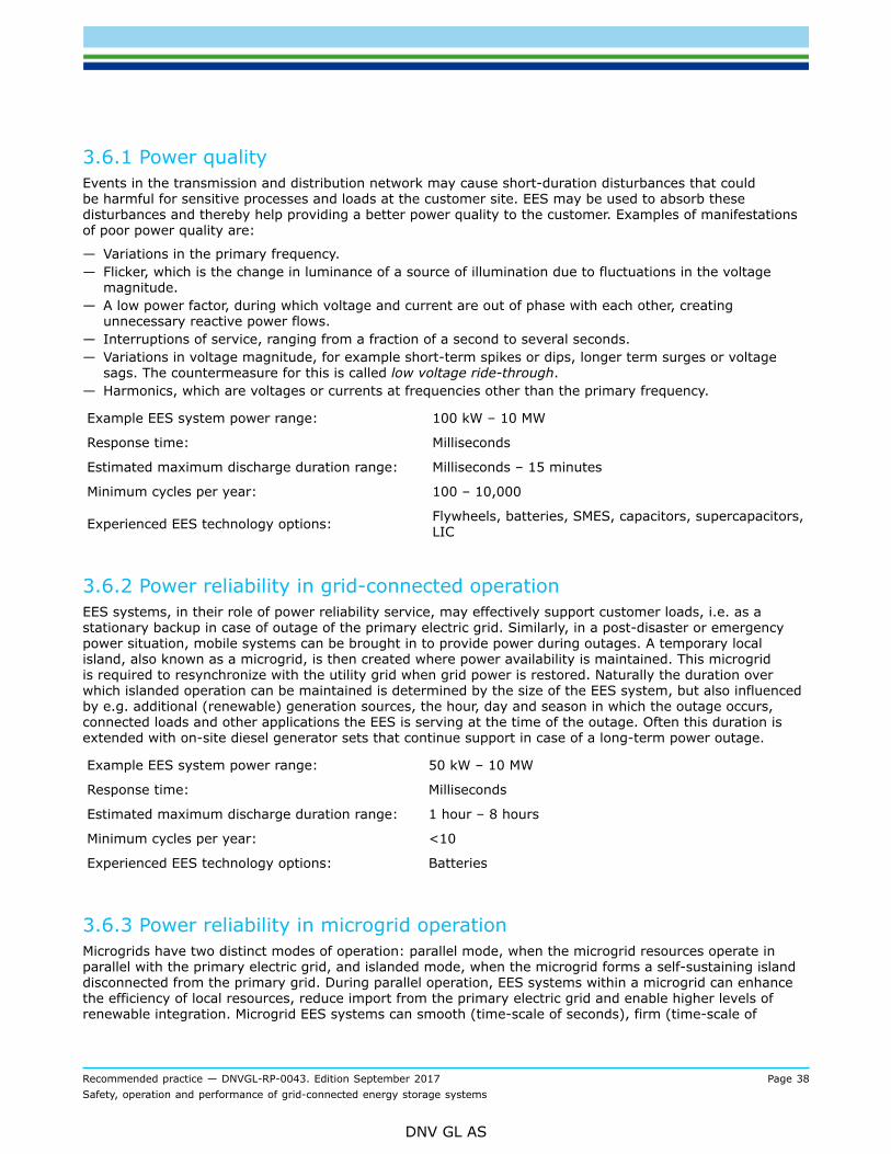
Recommended practice — DNVGL-RP-0043. Edition September 2017 Page 38Safety, operation and performance of grid-connected energy storage systems
DNV GL AS
3.6.1 Power qualityEvents in the transmission and distribution network may cause short-duration disturbances that couldbe harmful for sensitive processes and loads at the customer site. EES may be used to absorb thesedisturbances and thereby help providing a better power quality to the customer. Examples of manifestationsof poor power quality are:
— Variations in the primary frequency.— Flicker, which is the change in luminance of a source of illumination due to fluctuations in the voltage
magnitude.— A low power factor, during which voltage and current are out of phase with each other, creating
unnecessary reactive power flows.— Interruptions of service, ranging from a fraction of a second to several seconds.— Variations in voltage magnitude, for example short-term spikes or dips, longer term surges or voltage
sags. The countermeasure for this is called low voltage ride-through.— Harmonics, which are voltages or currents at frequencies other than the primary frequency.
Example EES system power range: 100 kW – 10 MW
Response time: Milliseconds
Estimated maximum discharge duration range: Milliseconds – 15 minutes
Minimum cycles per year: 100 – 10,000
Experienced EES technology options: Flywheels, batteries, SMES, capacitors, supercapacitors,LIC
3.6.2 Power reliability in grid-connected operationEES systems, in their role of power reliability service, may effectively support customer loads, i.e. as astationary backup in case of outage of the primary electric grid. Similarly, in a post-disaster or emergencypower situation, mobile systems can be brought in to provide power during outages. A temporary localisland, also known as a microgrid, is then created where power availability is maintained. This microgridis required to resynchronize with the utility grid when grid power is restored. Naturally the duration overwhich islanded operation can be maintained is determined by the size of the EES system, but also influencedby e.g. additional (renewable) generation sources, the hour, day and season in which the outage occurs,connected loads and other applications the EES is serving at the time of the outage. Often this duration isextended with on-site diesel generator sets that continue support in case of a long-term power outage.
Example EES system power range: 50 kW – 10 MW
Response time: Milliseconds
Estimated maximum discharge duration range: 1 hour – 8 hours
Minimum cycles per year: <10
Experienced EES technology options: Batteries
3.6.3 Power reliability in microgrid operationMicrogrids have two distinct modes of operation: parallel mode, when the microgrid resources operate inparallel with the primary electric grid, and islanded mode, when the microgrid forms a self-sustaining islanddisconnected from the primary grid. During parallel operation, EES systems within a microgrid can enhancethe efficiency of local resources, reduce import from the primary electric grid and enable higher levels ofrenewable integration. Microgrid EES systems can smooth (time-scale of seconds), firm (time-scale of

Recommended practice — DNVGL-RP-0043. Edition September 2017 Page 39Safety, operation and performance of grid-connected energy storage systems
DNV GL AS
minutes) or shift (time-scale of hours) intermittent renewable generation by providing instantaneous rampingand sustained energy throughput while charging or discharging. Renewable intermittency mitigation providedby EES increases the stability of low-inertia islanded microgrids. Shifting allows renewable energy to beutilized during periods of no or low generation. In addition, EES may operate in conjunction with fossil-fuelengine generators to increase the efficiency of the engines. This is performed through controls that scheduleEES operation such that high loading levels and hence high efficiency is maintained for operational fossil fuelengine generators.Under islanded operation, EES may perform the role of a grid forming resource by maintaining the frequencyand voltage of the islanded microgrid through real and reactive power controls. This may be performed inisochronous control mode where the EES operates as a swing generator and provides the system frequencyreference. Alternately, if another resource operates under isochronous control, the EES can operate underfrequency droop control such that the output of the storage system is adjusted as a result of measuredpower system frequency by applying a droop curve to its nominal real power output. With sufficient installedcapacity of renewables, EES can enable a microgrid without requiring fossil-based resources.
Example EES system power range: 50 kW – 10 MW
Response time: Milliseconds
Estimated maximum discharge duration range: 1 hour – 8 hours
Minimum cycles per year: 400
Experienced EES technology options: Batteries, supercapacitors, flywheels
3.6.4 Retail electrical energy time-shiftSimilar to electrical energy time-shift (see [3.2.1]), an EES system may be used by a local customer tocharge during off-peak hours (low electricity price) and discharge during peak hours (high electricity price).Customers may aim to increase the self-consumption of their locally generated (renewable) energy byusing local EES. If difference in energy prices is the main driver, this application is often referred to asarbitrage. Customers using an EES system for a retail time-shift application use the system based on thegoing customer’s retail tariff, whereas the (often larger) systems used in energy time-shift applications usethe electricity wholesale price.
Example EES system power range: 1 kW – 1 MW
Response time: Milliseconds
Estimated maximum discharge duration range: 1 hour – 6 hours
Minimum cycles per year: 50 – 250
Experienced EES technology options: Batteries
3.6.5 Demand charge managementIn specific geographic locations and utility jurisdictions, commercial customers are subject to capacitycharges (related to the maximum power capacity of the grid connection) and/or demand charges (related tothe maximum power actually consumed) by the electric utility or distribution system operator. These charges(i.e. fees or bills) may comprise of two separate tariffs – a non-coincident demand charge assessed on themaximum power demand of the monthly billing cycle and a peak demand charge assessed on the maximumcustomer power demand during peak hours over the monthly billing cycle. Generally, these charges areadditive. In dense urban areas subject to distribution and transmission system congestion, demand chargesmay be quite high. As a result, demand charge management – DCM (i.e. demand reduction) at peak periodscan result in substantial savings for the customer. Lowering of demand peaks is also known as peak shaving.

Recommended practice — DNVGL-RP-0043. Edition September 2017 Page 40Safety, operation and performance of grid-connected energy storage systems
DNV GL AS
Standalone behind-the-meter solar PV systems can reduce customer demand by a limited amount. However,this reduction cannot be guaranteed and the resulting savings cannot be ‘banked’ upon. The reason isthat the output of solar PV systems is intermittent and dependent on atmospheric and ground conditions.For example, a sudden cloud cover during the customer peak demand hour may jeopardize the demandreduction potential of the standalone solar PV system over the entire month. EES can complement solar PVsystems to reduce peak demand. They guarantee the demand reduction that may naturally accrue to solarPV systems, as well as reduce demand on their own. As such, EES may perform demand reduction with orwithout solar PV systems.For this application, the EES system generally undergoes one cycle a day, between 20 to 30 days a month,although more advanced profiles are possible depending on load profiles and local power pricing structures.The system may charge in the night from the electric grid. Solar PV+storage systems may have an incentiveto charge EES directly from solar PV output. In that case, the EES may charge in early morning whencustomer load is low or during peak solar production hours when solar output is greater than customer load.For solar PV+ storage systems, the EES generally discharges in early evening hours, when solar productionis low and customer load is high. EES controls forecast customer load, renewable production and other siteparameters generally over a 24-hour horizon and schedule storage discharging such that peak demand isreduced at the utility meter.Note that the EES system efficiency needs to be considered when calculating the potential benefit and thatthis EES application should be combined with other applications to be more economically viable.
Example EES system power range: 10 kW – 10 MW
Response time: Seconds to minutes
Estimated maximum discharge duration range: 15 minutes – 4 hours
Minimum cycles per year: 50 – 500
Experienced EES technology options: Batteries
Guidance note:A UK-specific type of demand charge management is triad avoidance, also called triad chasing. Triads in the UK are three half-hourperiods of highest demand on the grid, identified (using certain restrictions) after taking place, and determining network costs forlarge industrial and commercial consumers. Distributed generation plants can be compensated for their contribution in reducingtransmission capacity requirements. An EES system used for triad avoidance is operated with about one full-cycle per day during a100-day period to lower peak demand of a distributed area, in this way reducing power consumption during the triads. Incidentally,the UK government is expected to reduce benefits over the period 2018-2020, resulting in a less attractive business case for thisapplication.
---e-n-d---o-f---g-u-i-d-a-n-c-e---n-o-t-e---
3.6.6 Renewable power consumption maximisationRenewable power may be generated locally in different sizes, e.g. by a single household or by a privateenergy system such as a group of buildings behind a single retail energy meter. Similar to the demandcharge management, the EES system can be used to balance the local demand and generation. However, inthis application the EES is used to maximise the share of renewable power consumed locally, i.e. maximiseself-consumption of renewable energy. Reasons for this application may be decreased CO2 emissions,increased self-sufficiency or to increase fuel savings in microgrids.In this application, the EES system should be charged from renewable energy sources as much as possible,preferably always. The EES system should therefore be charged at a rate proportional to the linkedrenewable power production, so for example for solar + storage systems especially around noon and not atall during the night. The timing of the discharge may be chosen in combination with the previous application.In case of solar PV + storage the EES system undergoes one cycle a day (because of the daily solar cycle),between 20 to 30 days a month. In case of wind + storage, the EES system may undergo 1 or 2 cycles perday, depending on the daily wind and consumption cycles (consumption commonly have a morning peak andan evening peak, thereby enabling 2 full EES cycles per day).

Recommended practice — DNVGL-RP-0043. Edition September 2017 Page 41Safety, operation and performance of grid-connected energy storage systems
DNV GL AS
Note that also here the EES system efficiency needs to be considered when calculating the potential benefitsand that this EES application should be combined with other applications to be more economically viable.
Example EES system power range: 10 kW – 10 MW
Response time: Seconds to minutes
Estimated maximum discharge duration range: 15 minutes – 4 hours
Minimum cycles per year: 200 – 500
Experienced EES technology options: Batteries, redox flow batteries
3.7 Renewables integrationThe number of wind and solar installations on different scales is increasing globally. Also, their relative part inthe electricity generation mix is increasing. The intermittent nature of these renewable energy sources couldcreate grid congestions and voltage and frequency instability on different scales in the power system. EESapplications for renewables integration are meant to counter the intermittency or its impact on the powergrid.Several EES applications described in previous sections could support the integration of renewables witha variable power output. Several examples of storage applications as described in previous sections incombination with renewables are:
1) Renewables and EES operating in (retail) electrical energy time-shift operation:Operating (part of) the EES in a time-shift application and discharging it when energy is expensive(during peak hours) could improve the return on investment of the EES system and/or renewable energysource.This is also linked to ‘demand charge management’ and ‘maximising renewable power consumption’,which have been previously mentioned.
2) Renewables and EES operating in voltage support and/or power quality support:EES could provide a means to improve the supplied voltage and power quality from a renewable energysource, especially when the output of these renewable energy sources directly depends on, for example,local weather conditions.
3) Renewables and EES providing transmission congestion relief or transmission upgrade deferral:For specific renewable energy projects, EES could provide a solution that prevents transmissioncongestion and/or curtailment of the renewable generation, or defers transmission grid capacityincrease. This could for example be the case when an existing renewable energy plant (with constrainedtransmission connections) is enlarged with additional capacity.
In addition to the above examples, applications for EES specifically in combination with renewable energysources are described in the next subsections.
3.7.1 Ramp rate controlThe output of renewable energy sources like solar PV systems and wind turbines directly depends on localweather conditions. EES could provide a means to obtain a more stable energy output from renewablesources, thereby improving the predictability of renewable energy supply to the grid. One importantchallenge associated with variable renewable energy generation, especially solar and wind, is that therenewable power output can change rapidly over short periods of time (sub-seconds to minutes). Severalgovernments require renewable energy production sites to reduce the rate of change (i.e. the ramp rate)of the power output in order to be compliant with local grid codes pertaining to grid stability. This EESapplication in combination with renewable power generation is called ramp rate control of the renewablepower output. It is also called smoothing of the RES output.
Example EES system power range: 1 MW – 500 MW (depends on generation power)
Recommended practice — DNVGL-RP-0043. Edition September 2017 Page 42Safety, operation and performance of grid-connected energy storage systems
DNV GL AS
Response time: Milliseconds to seconds
Estimated maximum discharge duration range: 1 minute cyclic-repetitive – 4 hours
Minimum cycles per year: PM (application results in micro-cycles)
Experienced EES technology options: Batteries, redox flow batteries, supercapacitors, LAES
3.7.2 Generation peak shavingPeak shaving of renewable generation may have different reasons, like congestion management ofthe connection or the local grid, or preventing overproduction to prevent either system imbalance oroverproduction penalties, If renewable generation peak shaving means reducing the output power, this iscalled curtailment of the renewable generation, meaning a waste of energy. This is an undesired situation,solved by using an EES system to store the energy during peak shaving and release the energy again duringanother time interval. This application is therefore similar to ‘electrical energy time-shift’ but its purposediffers
Example EES system power range: 1 MW – 100 MW
Response time: Milliseconds to minutes
Estimated maximum discharge duration range: 2 hours – 6 hours
Minimum cycles per year: >250
Experienced EES technology options: PHS, CAES, LAES and batteries
3.7.3 Capacity firmingIn many cases, it is preferable to have a predictable constant output power from a generation source. An EESsystem can be used to enable this for a variable renewable energy source by charging when the RES outputis above a certain value and discharging when the RES output is below this value. This application is called‘capacity firming’. This results in an output power of the combined RES + storage system that is constantover a certain period of time (normally a number of hours). Capacity firming is a combination of ramp ratecontrol, energy time shift and peak shaving and can also be considered an extreme case of smoothing.
Example EES system power range: 1 MW – 500 MW
Response time: Milliseconds to minutes
Estimated maximum discharge duration range: 2 hours – 6 hours
Minimum cycles per year: >250
Experienced EES technology options: PHS, CAES, LAES and batteries
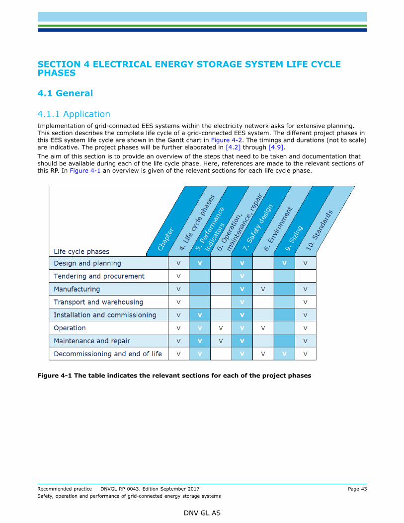
Recommended practice — DNVGL-RP-0043. Edition September 2017 Page 43Safety, operation and performance of grid-connected energy storage systems
DNV GL AS
SECTION 4 ELECTRICAL ENERGY STORAGE SYSTEM LIFE CYCLEPHASES
4.1 General
4.1.1 ApplicationImplementation of grid-connected EES systems within the electricity network asks for extensive planning.This section describes the complete life cycle of a grid-connected EES system. The different project phases inthis EES system life cycle are shown in the Gantt chart in Figure 4-2. The timings and durations (not to scale)are indicative. The project phases will be further elaborated in [4.2] through [4.9].The aim of this section is to provide an overview of the steps that need to be taken and documentation thatshould be available during each of the life cycle phase. Here, references are made to the relevant sections ofthis RP. In Figure 4-1 an overview is given of the relevant sections for each life cycle phase.
Figure 4-1 The table indicates the relevant sections for each of the project phases

Recommended practice — DNVGL-RP-0043. Edition September 2017 Page 44Safety, operation and performance of grid-connected energy storage systems
DNV GL AS
Figure 4-2 Gantt chart with the project phases of an EES system. Timings and durations areindicative
4.1.2 ReferenceFor supplementary guidelines reference is made to the applicable parts of:
— Sandia National Laboratories, DOE/EPRI 2013 Electricity Storage Handbook in Collaboration with NRECA,USA, Jul 2013.
— Energy Storage Operating Forum, A Good Practice Guide on Electrical Energy Storage, EA Technology,United Kingdom, Dec 2014.
— DNV GL, Guideline for Large Maritime Battery Systems, Norway, Mar 2014.
4.2 Design and planningThe design and planning phase includes the preparation and application design processes, including requestsfor permits and siting approval (e.g. to local authorities, land owners, fire department, etc.).
4.2.1 Business case and requirementsThe first step is to make a screening assessment, where the EES system’s primary functions and the outlineof its business case are described. Here, the opportunity should be described as well as the solution coveredby an EES system.The second step is to outline the grid service requirements. This is a description of what should beaccomplished and is independent of the technology. Communication with decision makers and key

Recommended practice — DNVGL-RP-0043. Edition September 2017 Page 45Safety, operation and performance of grid-connected energy storage systems
DNV GL AS
stakeholders to determine the minimum operating criteria is recommended. The functional requirementstypically include:
— Energy storage capacity— Power— Power quality requirements (voltage, load profiles, current waveforms, frequency)— Round-trip efficiency, number of load cycles— Ramp rate, response time— Interconnection requirements.
The value of an EES solution can be calculated based on the expected revenue of the EES solution andthe avoided costs. For this, an energy forecast and financial forecast should be made. The energy forecastconsists of a detailed energy demand study and an analysis of the EES solution (technology). Usingcalculations and modelling, a first year and multiyear estimates can be made. This preliminary energyprediction together with an estimate of the operation and maintenance costs should be used to make thefinancial analysis, i.e. due diligence. This financial forecast predicts the economic feasibility of the EESsystem project.Furthermore, any risks to the EES system’s ability to meet its functional requirements should be identified,and if such risks are severe, they should be mitigated. Addressing these risks early in the design phase willavoid loss of investments later.Cyber security is a particular type of risk, becoming apparent during operation and therefore often foundto be difficult to take into account during the design phase. However, if appropriately addressed then,cyber security becomes part of the product rather than requiring costly add-ons. Cyber security designrequirements should be provided by owners, system integrators and operators, who will benefit fromsignificant savings if the system is designed from the start with security in mind. Development of designrequirements should be based on security standards, for example IEC 62351 (protocol security, eventlogging, role based access control), IEC 62443 (industrial network and system security), or NERC CIP 005(electronic security for power and energy plants).
4.2.2 Authorities and permittingIn parallel to the screening assessment and in consideration of submitting information on the ESS installationas a component of any permitting process, any and all agencies or entities should be identified that wouldbe involved in the review and approval of the ESS and its intended installation and integration with thebuilt environment. This can include governmental agencies as well as private sector entities such asinsurance carriers. After identification of such agencies or entities, any requirements should be identified(e.g. rules, regulations, codes, standards, etc.) that they have adopted and would apply to the intendedESS project. Subsequently, preliminary plans and specifications should be prepared and a meeting heldwith those agencies and entities to make sure what is being proposed is acceptable with respect to theirrequirements and to identify any significant issues that need to be addressed, as well as firming up whatdocumentation they require as a component of their permitting and approval process. Such meetings shouldmake clear what information will be required about the ESS project to document compliance with applicablerequirements. It may take several meetings to sort out the final approved plans and specifications before anypermits are issued. Once issued, then construction and commissioning can begin subject to any inspectionand review by those agencies or entities during construction and final commissioning. During that processand beyond, it will also be very important to adjust the plans and specifications initially submitted to reflectthe as built condition of the ESS project.
4.3 Tendering and procurementOnce there is a valid business case, the tendering phase can start, often preceded by a request forinformation collecting information on supplier capabilities. Tendering can either be for the complete system,for separate components or turn key / EPC (Engineering, Procurement and Construction). In any case,project criteria should be outlined comprehensively and in detail. Apart from the functional requirements asmentioned above, the following requirements should be described in more detail:
Recommended practice — DNVGL-RP-0043. Edition September 2017 Page 46Safety, operation and performance of grid-connected energy storage systems
DNV GL AS
— Technical requirements might include: charging and discharging power, usable energy capacity, lifetime ofthe system (both calendar and cycle lifetime), end of life criteria, converter requirements, response time,efficiency.
— Physical requirements, such as operating temperatures, humidity, dimensional restrictions.— Safety requirements, see Sec.7.— Cyber security requirements, see section [7.4.9].— Environmental requirements, including decommissioning and end-of-life (EoL) disposal, see Sec.8.— Regulatory requirements, see App.B.— Relevant standards, see App.B.— Control requirements, including communication channels and protocols (requirements to communicate
with DSO/TSO control systems of active network management schemes), data and cyber security andcommunications (of alarms) between sub-systems. (See [6.5]).
Additional to the above criteria, the selection of supplier is based on:
— Price, including cost effectiveness, warranty / maintenance and performance guarantees.— Financial background of the supplier, deployment track record and ability to meet deadlines.— Single supplier or cooperation between separate manufacturers for certain EES system components.
In the contract agreement (procurement phase), it is advisable to mention all the above aspects. If theowner of the EES system is bound by contractual obligations for which the system is needed, the agreementshould state a penalty for delivery period overrun. Definitions in the agreement should be in line withthe definitions in Sec.2, especially so for EES performance definitions. Performance degradation over thelifetime of an EES system is application-specific and risk-inherent, as such warranty should be based upona usage profile expected and agreed on in advance. It should include remedies or compensation in case ofunderperformance. FIDIC standard forms of contracts are suitable template for EES system projects.
4.4 ManufacturingManufacturing requirements vary substantially depending on the technology used. However, commonrequirements do exist:
— traceability of the product— in-line and end-of-line testing— product certification, verification or qualification— operation certification and training requirements— security certification, verification or qualification, health qualification and safety regulations— type approval.
In case the supplier is a system integrator, the component manufacturers are responsible for manufacturing;if not (i.e. the EES is produced as one unit), then the supplier is also responsible for manufacturing. In allcases, the supplier is responsible for system design.Sec.7 elaborates on the supplier responsibility, certification and electrical safety in general.
4.4.1 Conformity assessmentIn established markets, such as PV panels and wind turbines, certification of manufacturing of components/systems (e.g. type certification/project certification of wind turbines/farms) is applied commonplace.However, for grid-scale energy storage systems, a comprehensive standard does not currently exist.To ensure that the ESS and the most important components comply with proper codes and standards,conformity assessment should be carried out, a two-step process consisting of testing and certification:
1) Testing of the ESS product or component parts to a set of proper standards to determine performanceagainst the provisions in the standard(s); factory acceptance testing (see 4.4.2) is part of this. Themanufacturer usually tasks a third party testing entity (ideally accredited) to do this and obtains a reporton the item(s) tested;

Recommended practice — DNVGL-RP-0043. Edition September 2017 Page 47Safety, operation and performance of grid-connected energy storage systems
DNV GL AS
2) Certification or listing, involving a third party (also ideally accredited) inspecting subsequent productionat the factory and reviews relevant documentation and provides the manufacturer a correspondingcertificate to say what is produced meets the test standard(s).
4.4.2 Factory acceptance testingAs part of conformity assessment, factory acceptance testing (FAT) should be performed to reasonably provesystem scale performance and compliance with codes, standards, rules and regulations applicable to theESS project. In case of transport by a third party (not the contractor or purchasing party), the FAT reportprovides evidence of the state of the system before transport and should be used to later assess if a defecthas occurred during transport.The FAT plan must be agreed upon by both the supplier and the purchasing party and should provequantifiably that the EES system is safe, reliable and per specification. Sec.5 elaborates on the performanceindicators that are relevant for an EES system. It is recommended to verify the relevant performanceindicators during the FAT procedure and to design the FAT plan accordingly as a separate test for each deviceor as a system level test. The system level tests that should be included in the FAT are described in the IEEE1547 standard. Tests should be unambiguously defined and should produce a quantifiable result. Pass/failcriteria should be designated for each test in conformity with the agreed upon specifications of the systemand standards. As performing a FAT has potential hazards, before conducting any activities risks should beassessed and mitigating measures implemented.In case full FAT testing as mentioned above is not feasible, such tests may be included in the site acceptancetesting (SAT) testing and/or limited in extent, if agreed on by all stakeholders involved. For example, in somecases power output may be tested on a fraction of the rated capacity to prove functionality.
Guidance note:FAT is an activity that marks an important milestone in the realisation process of an EES system and concludes the manufacturingprocess. FAT refers to both and is the combination of a document describing the testing procedure (FAT plan), and the execution ofthe procedure in a controlled environment at preferably a supplier’s or alternatively at a customer’s facility. The principal purposeof FAT is that, once completed successfully and provided certain additional (contractually agreed) acceptance criteria are met, thepurchasing party will declare the system as satisfying the contract and deliver final payment or activate contractual obligations.
---e-n-d---o-f---g-u-i-d-a-n-c-e---n-o-t-e---
4.4.3 Warranty and after-sales supportIn the contract with the supplier a relevant warranty period should be agreed on. The SAT is the startingpoint for the warranty period. In the warranty agreement, the intended and permissible use of the EESsystem should be clearly described in order to avoid disputes on warranty, particularly when the utilisationof a particular system has been changed from initial intent. The performance of the battery at SAT andend of warranty should be defined with key performance indicators (KPIs). To keep track of the system’sperformance and avoid disputes, an independent party could be involved for data evaluation. Also, it isrecommended to make agreements on the after-sales maintenance support. Additionally, the supplier shouldoffer extended warranty services, for example for preventative maintenance, availability or energy deliveryassurance.The warranty agreement should at least define what is under warranty (e.g. capacity, availability and/orround-trip efficiency) under which conditions and exceptions and which actions will be undertaken whensystems does not perform according agreements.The warranty agreement should include the following topics:
— definition of the system under warranty— warranty period— system use profile – describing the application the system will be used for (see Table 3-1), providing
the corresponding usage profile and describing the consequences to the warranty agreement in case theprofile changes or additional applications will be added to the system. Alternatively, the parties can definewarranted energy throughput within certain limitations.

Recommended practice — DNVGL-RP-0043. Edition September 2017 Page 48Safety, operation and performance of grid-connected energy storage systems
DNV GL AS
— KPI values, definitions and measuring point at begin and end of warranty period— actions to be undertaken when system does not match agreements— independent third party data access to avoid disputes.
The after sales support should include the following topics:
— availability of support – remote and on-site— mean time till repair (MTTR)— O&M manuals and training— type, frequency and responsible party of maintenance and repair work.
4.5 Transport and warehousingAfter a successful FAT, the complete EES system or its individual components should be transported to thesite location. The following recommendations should be considered when transporting the EES system:
— Depending on the nature of the system or subsystem, the United Nations (UN) Recommendations onthe transport of dangerous goods may apply. For instance, it describes the specific requirements whentransporting lithium-based batteries (Section 38.3 Lithium metal and lithium ion batteries).
— Mechanical EES systems might be very heavy and/or large and reside under regulation for heavy vehicletransport.
— ESS systems that, as a whole, are to be handled as dangerous goods can be made safe for transportby separating the dangerous substances from the rest of the system. For instance, redox flow batterysystems that have been drained of all active materials and cleaned can be treated like any other piece ofprocess equipment, and are not subject to transport restrictions for dangerous goods. Supercapacitors canbe fully discharged and short-circuited, which allows transportation in a secure de-energised state.
— If components of the system are transported by air, the Dangerous Goods Regulations of the InternationalAir Transportation Association (IATA) may apply.
It might be the case that components of the EES system need to be stored in a warehouse for a certainamount of time. Battery EES systems require safety precautions during the time that they are stored.More information on e regulations for transport and warehousing safety is described in section [7.6.1].Warehousing may influence the lifetime of ESS components, depending on the technology. Short-circuitedsupercapacitors can be stored without significant ageing.
4.6 Installation and commissioning
4.6.1 Installation activitiesThe ESS installation activities can start as soon as all necessary pre-installation permits have been grantedand the work needed to prepare the site for the envisioned construction has been completed. The EESsystem supplier should provide the installation documentation. This documentation should include aninstallation and operation manual, with instructions on the installation and interfacing procedures. It shouldalso include a list of pre-installation checks to ensure that the components have been delivered correctly.The pre-installation checks also form a part of the SAT. A combination of a cybersecurity policy check and acheck if according measures are in place should be part of the pre-installation checks, the scope of checkingshould be proportional to the risk that is to be covered. The supplier concludes the installation activities bycommissioning, resulting in a functional EES system in place which is ready for and expected to pass SAT.
4.6.2 Site acceptance testingAfter the installation of the EES system is finished, SAT should be performed. SAT is an activity that marksan important milestone in the realisation process of an EES system and concludes the installation process.The principle purpose of the SAT is to ensure that the system has been tested in accordance with client-approved test plans to prove that the system is installed properly, is interfaced correctly with all other
Recommended practice — DNVGL-RP-0043. Edition September 2017 Page 49Safety, operation and performance of grid-connected energy storage systems
DNV GL AS
systems/peripherals, is implemented with the appropriate cybersecurity measures and is delivered perspecification. SAT includes detailed site testing, testing of all interfaces, application testing and an acceptancetesting procedure with proper acceptance criteria. This task should not be underestimated and needs aclose cooperation between the EES system operator, the EES system supplier, the supplier(s) of the EEScomponents and the grid operator. A key input document for the SAT is the interface control document (ICD)describing all physical and communication interfaces and their properties. Local inspectors, AHJs, and/orfire service officials may also be involved in this process, e.g. to ensure proper operation and grant any finalpermits for the operation of the system.When the EES system is installed and integrated into the system of the operator, a cyber security riskassessment should be performed, making sure all cyber security risks have been identified and mitigatedappropriately. The cyber security risk assessment should identify the threats to the system, preventivebarriers for these threats and reduction barriers for these incidents (mitigation measures). Furthermore, therobustness of these mitigation measures should be assessed, assigned to action owners and checked forcompletion, providing appropriate focus on the security implementation and awareness of all participants.The cyber security risk assessment should be part of the security management system defined by ISO27001standard. This cyber security risk assessment should be repeated periodically to make sure that new risks arecorrectly mitigated.
4.6.3 Handover/takeoverAfter performing any tests needed, the commissioned system can be handed over to the owner. Uponhandover/takeover, transfer of responsibilities takes place, all documentation is handed over including riskassessment documentation and training of personnel is performed.Experience has shown that issues often occur at the interface between systems. The interface between theEES system and the grid is an area that should receive special focus when assessing the SAT results.Also, a system components description should be made available by the EES system supplier. This documentshould contain at least:
— Hardware manual: description of the hardware.— Firmware manual: description of the firmware as well as a complete overview of which units contain
upgradeable firmware.— Internal wiring diagram.— External wiring diagram.— Function description: description of the functionality of the EES system.— Technical specification: specification covering the technical details of the EES system such as power and
energy capabilities, temperature of operation, system lifetime etc., and maintenance and repair manual.— bus communication protocol: specification of the communication between the EES system and the rest
of the system including communication protocol and available messages with explanation of those. Thisincludes all signals for regular operation as well as all warning and error signals.
4.7 OperationAfter the installation and commissioning, the responsibility for safe operation and asset management hasbeen transferred to the operational team. Although in some cases the manufacturer of certain componentsremains responsible for the maintenance of specific components as part of a service agreement.The normal use of the EES system should be fully automatic. There should be no need for manual interaction.The operational phase of the EES system is covered in more detail in Sec.6, including more information aboutthe operational manual ([6.4.1]). Safety precautions are described in more detail in Sec.7.During operation, the operational team should be able to monitor the EES. Cyber security monitoringidentifies anomalous behavior to detect a possible breach in a very early stage. A security breach could bedefined as an unauthorized change in the system that could alter the functionality of the system. As systemavailability generally has the highest priority, an integrity breach is a big risk.

Recommended practice — DNVGL-RP-0043. Edition September 2017 Page 50Safety, operation and performance of grid-connected energy storage systems
DNV GL AS
4.8 Maintenance and repair
4.8.1 MaintenanceA plan for systematic maintenance and function testing should be kept on location showing in detail howcomponents and systems should be tested and what should be observed during the tests. Visual proofof periodical and mandatory service should be kept in place. Maintenance may be performed manuallyor automated. In case of manual maintenance, a higher level of safety precautions needs to be taken.Maintenance, preventative replacement or additions to the system can contribute to ensuring performanceover time. Downtime or partial unavailability of the EES system should be taken into account in theoperational expenses. Whenever components have been replaced or repaired, it should be checked whetherthis change affects any permits and applicable regulations.
4.8.2 RepairFor more information on repairs, see [6.4.2] and [6.6].For more information on safety measures that may apply to repairs, see [7.6.3].
4.8.3 Updates and patchesA software update and patch policy and process should be in place. This process should contain at leasthow to perform updates, when to perform updates, which updates should be installed, how to transfer thesoftware to the system (network or secure USB), using dedicated systems (jump hosts, laptops, remote),perform integrity check before installation and who needs to be involved during the process.
Guidance note:The firmware or the software of the EES system sometimes needs updates. Possibly due to the need of new functionality or to fixa security issue. Due to the high availability requirements, these updates are postponed. The system becomes more vulnerable toknown attacks. Furthermore, changing and updating the software creates the possibility to inject malware.
---e-n-d---o-f---g-u-i-d-a-n-c-e---n-o-t-e---
4.9 Repurposing and end of lifeAt some stage in its life cycle, internal or external key parameters of an EES system may have changed insuch a way that its performance, whether technical, financial or otherwise, is significantly negatively affectedor an alternative application may be considered for the system.Examples of such cases are:
— One or more key components have degraded performance, so the EES system has a lower power or lowerenergy storage capacity.
— One or more key components are no longer functional and maintenance / replacement is expensive.— External technical specifications, e.g. regarding grid connection, have changed and cannot be met without
impacting EES system operation.— Changes in the market situation, e.g. in prices or regulations, make the current situation less profitable or
make other situations more profitable (e.g. operation in other markets).— Legal or regulatory issues, including warranty issues, make operation as before risky or no longer
possible.
At this point, the feasibility of the EES system’s current situation should be thoroughly investigated (see[4.9.1]), as well as any alternative options. Unchanged operation as most worthwhile option may be anoutcome of such an investigation. It may also be an alternative option is considered more feasible, atwhich point it may be decided to repurpose the EES system; the EES system then re-enters the Design andPlanning phase and all subsequent phases (see [4.2] through [4.8]).

Recommended practice — DNVGL-RP-0043. Edition September 2017 Page 51Safety, operation and performance of grid-connected energy storage systems
DNV GL AS
If neither continued operation nor alternative options are considered feasible, EoL of the system is reached(see also [6.5.3]). The EES system then needs to be decommissioned. Part of the system or individualcomponents can be recycled or re-used.
4.9.1 Repurposing of the electrical energy storage systemIn order to identify the need for a system change at an early stage, continuous evaluation of the performanceof the EES system is recommended. Several measures can be taken to improve the operational and economicperformance of the EES system, such as refurbishment, adding new components, changing the applicationand change of the location.If the performance evaluation give rise to consider a system change, a screening assessment should be done.In this screening assessment, the outline of the business case is described. This includes a description of theopportunity as well as the solution covered by the EES system. It is also recommended to re-evaluate theenergy and financial forecasting to find alternative business cases.In case the screening assessment leads to the conclusion that an EES system change is an interesting option,a new project is started and technical capabilities, warranties, liabilities, safety, applicable regulations andrecycling responsibilities need to be re-evaluated. In the situation that there is no alternative valid businesscase for the EES system, normal operation can continue or decommissioning can be considered.In the screening assessment, it environmental benefits may be calculated to compare the repurposed systemto the previous situation. Environmental benefits should be calculated by compilation and evaluation of theinputs, outputs and the potential environmental impacts of a system throughout its life cycle e.g. a life cycleassessment (LCA), see 3.2 of ISO 14040.For more information on the residual value of an EES system, see [10.4].For safety considerations regarding second life systems, see [7.5.1.7].
Guidance note:The following description is an example of how to compare environmental benefits in an LCA for an EES system. First choose afunctional unit (e.g. kWh or GHG equivalents) and define the new application with the appropriate lifetime. Compare the differentscenarios:
1) Base case scenario with a new EES system for the chosen application. Calculate the cost in the chosen functional unit forproduction, transport, use of new EES system and recycling
2) Second scenario with a repurposed EES system for the chosen application. Calculate the cost in the chosen functional unit forx% for production, refurbishment, transport, use of repurposed EES system and recycling
For the second scenario, it is important to calculate the correct percentage of the production cost to the repurposed EES system.One example to calculate this percentage is to look at the proportion of total energy throughput of the first and repurposedapplication. Production cost of the repurposed EES system is then partly (x%) assigned to the second scenario. The lifetime ofthe chosen application is also important in the LCA calculations because the new EES system will probably last longer than therepurposed EES system.
---e-n-d---o-f---g-u-i-d-a-n-c-e---n-o-t-e---
4.9.2 Decommissioning and recyclingAn EES system that does not meet the performance requirements, where repairs do not solve the problemand where change in EES system does not lead to a profitable alternative business case, reached its EoL.After an EoL shutdown procedure, such an EES system should be de-installed, disassembled, removed fromthe site, transported and its components should be reused and/or recycled. If possible, the EES systemshould be de-energised safely before any other steps are taken. Before transport, it should be made surethat the EES system and its components are safe to transport.An EoL treatment plan describing all EoL activities should developed, documented and financed duringsystem deployment to prevent a stranded resource to be left without any support or commitment fordecommissioning.For decommissioning the energy storage system, the appropriate technical guidelines from the manufacturershould be consulted. Before the actual decommissioning, the EES system needs to be checked for hazardous
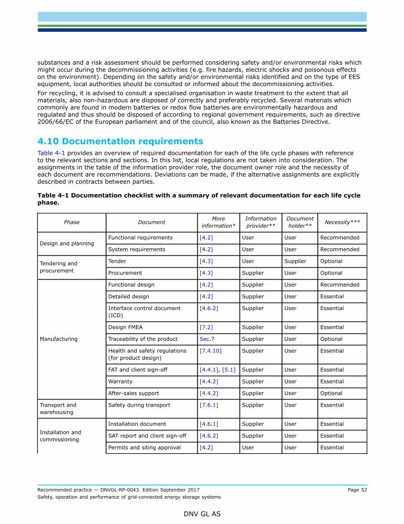
Recommended practice — DNVGL-RP-0043. Edition September 2017 Page 52Safety, operation and performance of grid-connected energy storage systems
DNV GL AS
substances and a risk assessment should be performed considering safety and/or environmental risks whichmight occur during the decommissioning activities (e.g. fire hazards, electric shocks and poisonous effectson the environment). Depending on the safety and/or environmental risks identified and on the type of EESequipment, local authorities should be consulted or informed about the decommissioning activities.For recycling, it is advised to consult a specialised organisation in waste treatment to the extent that allmaterials, also non-hazardous are disposed of correctly and preferably recycled. Several materials whichcommonly are found in modern batteries or redox flow batteries are environmentally hazardous andregulated and thus should be disposed of according to regional government requirements, such as directive2006/66/EC of the European parliament and of the council, also known as the Batteries Directive.
4.10 Documentation requirementsTable 4-1 provides an overview of required documentation for each of the life cycle phases with referenceto the relevant sections and sections. In this list, local regulations are not taken into consideration. Theassignments in the table of the information provider role, the document owner role and the necessity ofeach document are recommendations. Deviations can be made, if the alternative assignments are explicitlydescribed in contracts between parties.
Table 4-1 Documentation checklist with a summary of relevant documentation for each life cyclephase.
Phase Document Moreinformation*
Informationprovider**
Documentholder** Necessity***
Functional requirements [4.2] User User RecommendedDesign and planning
System requirements [4.2] User User Recommended
Tender [4.3] User Supplier OptionalTendering andprocurement Procurement [4.3] Supplier User Optional
Functional design [4.2] Supplier User Recommended
Detailed design [4.2] Supplier User Essential
Interface control document(ICD)
[4.6.2] Supplier User Essential
Design FMEA [7.2] Supplier User Essential
Traceability of the product Sec.7 Supplier User Optional
Health and safety regulations(for product design)
[7.4.10] Supplier User Essential
FAT and client sign-off [4.4.1], [5.1] Supplier User Essential
Warranty [4.4.2] Supplier User Essential
Manufacturing
After-sales support [4.4.2] Supplier User Optional
Transport andwarehousing
Safety during transport [7.6.1] Supplier User Essential
Installation document [4.6.1] Supplier User Essential
SAT report and client sign-off [4.6.2] Supplier User EssentialInstallation andcommissioning
Permits and siting approval [4.2] User User Essential
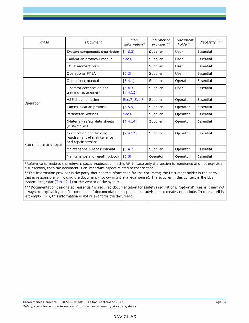
Recommended practice — DNVGL-RP-0043. Edition September 2017 Page 53Safety, operation and performance of grid-connected energy storage systems
DNV GL AS
Phase Document Moreinformation*
Informationprovider**
Documentholder** Necessity***
System components description [4.6.3] Supplier User Essential
Calibration protocol/ manual Sec.6 Supplier User Essential
EOL treatment plan Supplier User Essential
Operational FMEA [7.2] Supplier User Essential
Operational manual [6.4.1] Supplier Operator Essential
Operator certification andtraining requirement
[6.4.3],[7.4.12]
Supplier User Essential
HSE documentation Sec.7, Sec.8 Supplier Operator Essential
Communication protocol [6.5.9] Supplier Operator Essential
Parameter Settings Sec.6 Supplier Operator Essential
Operation
(Material) safety data sheets(SDS/MSDS)
[7.4.10] Supplier Operator Essential
Certification and trainingrequirement of maintenanceand repair persons
[7.4.12] Supplier Operator Essential
Maintenance & repair manual [6.4.2] Supplier Operator EssentialMaintenance and repair
Maintenance and repair logbook [6.6] Operator Operator Essential
*Reference is made to the relevant section/subsection in this RP. In case only the section is mentioned and not explicitlya subsection, then the document is an important aspect related to that section.**The Information provider is the party that has the information for the document; the Document holder is the partythat is responsible for holding the document (not owning it in a legal sense). The supplier in this context is the EESsystem integrator (Table 2-4) or the vendor of the system.
***Documentation designated “essential” is required documentation for (safety) regulations, “optional” means it may notalways be applicable, and “recommended” documentation is optional but advisable to create and include. In case a cell isleft empty (“-”), this information is not relevant for the document.
Recommended practice — DNVGL-RP-0043. Edition September 2017 Page 54Safety, operation and performance of grid-connected energy storage systems
DNV GL AS
SECTION 5 PERFORMANCE INDICATORSThe performance of an EES system can be technology- and application-agnostically treated like a black box,except for few technology-specific properties which need to be addressed. Note that performance indicatorsmay be application-specific i.e. not directly applicable to other applications. In any case, it is of the utmostimportance that performance indicators are carefully defined and relevant for the applicable technology andapplication, which is the aim of this section.
5.1 Power
5.1.1 Maximum continuous powerFor many EES technologies the maximum continuous power is a function of the system’s actual operationalparameters, and is mainly determined by thermal boundary conditions (i.e. when all components are inthermal equilibrium at a safe temperature). It can be different depending on the SoC/SOE and whether theEES system is being charged or discharged. An appropriate representation is the power graph, giving themaximum continuous power depending on the systems SOE (see Figure 5-1). Important maximum pointsshould be stated in a table. If a single power rating figure across the entire SOE range is required, the lowestpoint of the power graph should be used, representing the maximum power that can be guaranteed by thesystem without further restrictions.Feeding reactive power to the grid does not charge or discharge the EES system; it is a feature of theconverter (if part of the ESS configuration). For a given converter usually the maximum apparent power isfixed. Thus, the vector sum of active and reactive power has to comply with the apparent power limitation.Some converters may additionally have a dependency of the active power on the reactive power. To cover allpower output options, a plot showing active power versus reactive power is recommended.The power recovery unit of a CAES or LAES system can also provide reactive power by controlling the powerfactor (cos phi), provided the power recovery unit is a synchronous generator. Furthermore, the powerrecovery unit could be operated as a synchronous condenser when not providing active power, even when thesystem is in charge.Unit: kW, kVAr.
5.1.2 Peak powerDependent on the technology, the maximum peak power a system could deliver for a short period of timevaries from its continuous power. Together with the peak power the duration for which it could be deliveredshould be stated. Both are a function of the state of energy. Also, both are dependent on the properties ofthe whole system. Hence, all system components (storage, converter, cooling, etc.) should be capable todeliver the peak power for the stated time period. The peak power should be given as a singular curve withinthe power graph. Important maximum points should be stated in a table (see guidance note).Unit: kW

Recommended practice — DNVGL-RP-0043. Edition September 2017 Page 55Safety, operation and performance of grid-connected energy storage systems
DNV GL AS
Figure 5-1 Example power graph for continuous power and peak power
Guidance note:Table 5-1 below gives an example how the maximum continuous power and the peak power should be stated.
Table 5-1 Example maximum continuous power and peak power table
SOE Max. cont. Power SOE Peak Power Duration
0% 700 kW 0% 800 kW 8 s
4% 900 kW 30% 1050 kW 5 scharge
100% 900 kW
charge
100% 1050 kW 5 s
100% - 860 kW 100% - 1000 kW 5 s
45% - 860 kW 20% - 1000 kW 5 sdischarge
0% - 650 kW
discharge
0% - 750 kW 8 s
The sizing of the converter will influence EES system performance and design should be taken into account with regard tothe requirements of the application. If the maximum power output of the converter greatly exceeds the application’s powerrequirements, it is likely that the converter operates on a less efficient level (lower efficiency at lower output power level). This isdue to the efficiency over power graph typical for a converter.The definition of power is important, and losses in the system should be considered for accurate representation. The power, whichis required by an application, must be provided at the POC. This is the net AC power. Upon discharging, the storage medium mustsupply the net required power at the POC, plus the power loss caused by the transformer(s), converter(s) and other equipmentinside the system such as HVAC, switchgear, cabling and fuses. This is the gross direct current (DC) power (at the point ofconnection of the DC bus to the converters). Also, the energy of the storage must be sized appropriately to cover these loses, sothat the energy which is required by the application can be provided constantly (at the power which is required).
---e-n-d---o-f---g-u-i-d-a-n-c-e---n-o-t-e---

Recommended practice — DNVGL-RP-0043. Edition September 2017 Page 56Safety, operation and performance of grid-connected energy storage systems
DNV GL AS
5.2 Energy
5.2.1 Actual energy capacityThe actual energy capacity represents the usable energy content of an EES system and may stronglydepend on the charge/ discharge power, the environmental temperature and the SOH. This value can differsignificantly from the manufacturer’s specifications under different conditions and is likely to decrease overthe lifetime of the system. The limitations agreed upon between the supplier and user restrict the usablecapacity below what is technically possible (deep discharge). Agreed upon limitations, such as minimum andmaximum cell voltages are set forth to ensure prolonged lifetime and limit warranty.Unit: Wh
5.2.2 Installed capacityDue to physical or chemical limitations for most storage technologies the installed energy content is oftenhigher than the normally usable energy content (see Sec.2 on depth of discharge).Unit: Wh
5.2.3 Deep dischargeBesides the energy content that is available, an EES system could be capable of deep discharge. Often deepdischarge reduces the lifetime of the EES system or the system might provide only a reduced power output.It should be stated whether an EES system is capable of deep discharge, if this is allowed, to what DODlevel and how often it could be deep discharged. A power versus DOD graph for deep discharge should beprovided. (see [5.1.1]). After a deep discharge a cooling period as well as a special charging procedure maybe required, so it should be stated if this is necessary. The lifetime of some technologies is not affected bydeep cycling, for instance capacitors can be fully discharged without reducing the expected lifetime.Units: kW and s (for power graph), % (for DOD), kW (for peak power), s (cooling period)
5.3 DynamicsFactors governing the dynamics of an EES system include initial delay, ramp rate, response time, responsetime in standby and turn-on time.
Guidance note:The aforementioned factors together shape an EES system’s dynamic response, an indicator of the system’s ability to rapidly andrepeatedly vary the direction of power flow. This is embodied in applications such as frequency regulation or renewable firming –where the system is commonly commanded to switch back and forth between charge and discharge several times within a minute.
---e-n-d---o-f---g-u-i-d-a-n-c-e---n-o-t-e---
5.3.1 Ramp rateThe ramp rate is the increase of the EES system power per unit of time. The maximum ramp rate resultsfrom all system components (storage, converter, cooling, controls, …) and could be dependent on thesystem’s state of energy. The maximum ramp rate is defined as the change of power between 10% and90% of the maximum power value divided by the corresponding ramping time interval. The ramp ratecapability may be asymmetric, i.e. the maximum ramp rate may be different for charging and discharging.Furthermore, the system may dwell for a certain time at zero power for technical reasons, when the powersetpoint crosses zero.Unit: kW/s

Recommended practice — DNVGL-RP-0043. Edition September 2017 Page 57Safety, operation and performance of grid-connected energy storage systems
DNV GL AS
5.3.2 Response time in normal operationResponse time in normal operation is the delay between the event requiring a change in output power, andthe time required by the system for the output power to reach the new level. An event can be a commandthrough an interface, or a grid event such as a voltage or frequency change. It is determined by the ramp-up time (see [2.3.3]) and the delay caused by latency of detection, communication and other systemcomponents that need to set up before a power change can be performed.Unit: s or ms
Guidance note:When testing, response time should be determined by collecting high resolution time series data of both the power commands andthe actual power output from the EES system.The system operator should provide input on the testing approach, to prevent excessive data file sizes e.g. for multi-hour chargecycles. Suggested approaches may for example be to collect data at millisecond intervals only around charge command changes oronly for a limited subset of the full set of efficiency tests.
---e-n-d---o-f---g-u-i-d-a-n-c-e---n-o-t-e---
5.3.3 Response time in stand-byIf the EES system provides a stand-by state, the initial delay and the response time from stand-by until thenew power setpoint is reached should be measured and reported.Unit: s
Guidance note:The stand-by state means, for example, a state in which the EES system is not providing active or reactive power to the grid, butin which all subsystems (including generator or converter) and auxiliary subsystems are powered up and in a certain stand-bymode. The stand-by mode should be defined by the EES system supplier or system integrator.
---e-n-d---o-f---g-u-i-d-a-n-c-e---n-o-t-e---
5.3.4 Turn-on timeIf the EES system provides an off-state, the turn-on time should be stated, i.e. the time interval from the offstate until the system starts to ramp up power. The turn-on time is an extended version of the initial delay.Turn-on time typically involves booting up of control computers, power-on system test routines etc., and isencountered only once.Unit: s
5.4 EfficiencyFor all EES systems, efficiency describes the amount of energy of the system that can be retrieved fromthe system during its operation compared to the total input energy. The system boundary to determine theefficiency is shown in Figure 2-1. It includes all components of the EES system and all energy passing thesystem boundary should be taken into account. For determining efficiency, the environmental conditions,the duty cycle profile (this may include one or more, identical or different, cycles) and the initial and finalSoC should be specified. In general, the auxiliary consumption is included in the efficiency calculation asenergy losses, both in charging and discharging mode (see [2.3.3]). However, in some situations auxiliaryconsumption is excluded from the main efficiency calculation, for example when this is under a separatemeter or supply. Even if the auxiliary load is metered powered separately, it is good practice to reportefficiency with and without auxiliary power consumption.Recommended test protocols for measuring system efficiency in various types of services can be foundin PNNL report PNNL-22010 Rev 2 / SAND2016-3078 R, Protocol for Uniformly Measuring and Expressingthe Performance of Energy Storage Systems, available online at http://energymaterials.pnnl.gov/pdf/PNNL-22010Rev2.pdf.
Recommended practice — DNVGL-RP-0043. Edition September 2017 Page 58Safety, operation and performance of grid-connected energy storage systems
DNV GL AS
Guidance note:It may be of interest to check the efficiency calculation methodology created by the Technology & Value Assessment Committee ofthe European Association for the Storage of Energy (EASE): TVAC WG1 Storage efficiency calculation methods, available online athttp://ease-storage.eu/wp-content/uploads/2016/03/Storage_efficiencies_EASE_Final.pdf
---e-n-d---o-f---g-u-i-d-a-n-c-e---n-o-t-e---
5.4.1 Efficiency mapThe EES system efficiency is a combination of the efficiencies of all system components described in[2.2] and it generally depends on the operating point, the charge/discharge cycle used and the operatingconditions. Therefore, the EES system efficiency should be given in the form of an efficiency map, i.e. notjust as a single figure. This map (in a two-dimensional graph or a table) gives the efficiency for a numberof system states, covering the entire relevant range for the EES system application, defined by charging/discharging power (on the y-axis of the graph) and the initial SOE or initial SoC (on the x-axis).This classification allows for the analysis of the system behaviour within the field of application as well as thecomparison of different storage technologies. To determine the efficiency map, charge and discharge testsshould be conducted that cover all possible SOE/SoC levels of the system.An efficiency map should include a description of the test conditions, including at least the operatingtemperature, agreed upon by system supplier, grid operator and system owner.For efficiency calculations and testing procedures, reference is made to IEC 61427-2.Unit: % (for every agreed combination of power and state of charge)
5.4.2 Round-trip efficiencyThe round-trip efficiency is the ratio between the energy retrieved and the energy supplied to the systemwhen a charge-discharge cycle is performed between two defined states of charge at a given power level.For an energy storage system, at least the round-trip efficiency of the system between 0% SOE and 100%SOE at the system’s continuous power rating should be specified. In addition, round-trip efficiencies betweenpartial SOE levels at various power levels may be given. Since the actual SOE range and power levels atwhich a storage system will operate are strongly application dependent, these efficiency figures should bedetermined between SOE levels and at power levels that are representative for the final application of thesystem. Efficiency calculations for these tests are broadly defined (as referenced in IEC 61427-2, and in theProtocol for Uniformly Measuring and Expressing the Performance of Energy Storage Systems PNNL-22010,rev 2 March 2016) as the ratio of total AC power output to total AC power input at the POC, as measuredover a given period of time.One-way efficiency should not be calculated by taking the square root of the round-trip efficiency, but ratherby actual charging and discharging tests.Unit: %
Guidance note:Round-trip efficiency is dependent on several factors including but not limited to temperature, power and SoC range, includingpartial discharge cycles. Actual EES application profiles will operate batteries under a wide range and combination of theseconditions, thus making round-trip efficiency difficult to approximate. Current requests for offers from utilities in the United Statesare requiring that vendors state the minimum, maximum and average efficiency of a given EES system. Thus, it is recommendedthat these values be reported based on the result of testing a given EES system on a specific application duty cycle profile (createdfor the EES system’s specific application or an approximation provided by a public document such as the PNNL protocol referencedabove). A basic round-trip efficiency measurement can be done by performing a series of full charge-discharge cycles at thenominal (dis)charge rate, employing the system’s full capacity. In practice, however, the efficiency figure determined in this waymay not be representative for the EES system’s real-life efficiency.
---e-n-d---o-f---g-u-i-d-a-n-c-e---n-o-t-e---

Recommended practice — DNVGL-RP-0043. Edition September 2017 Page 59Safety, operation and performance of grid-connected energy storage systems
DNV GL AS
5.4.3 Self-discharge rateThe self-discharge rate describes the reduction of the energy content (relative to actual energy capacity)of an EES system while the system idles. It includes the energy consumption of all system components.For some technologies, the self-discharge rate is dependent on the SOE, in which case it should be givenas a function of the SOE or as a graph. The self-discharge rate may also be dependent on environmentalconditions (such as temperature), EES system age and usage history (e.g. high temperature operation orovercharge events); applicable conditions and any available and applicable age / history information shouldtherefore be provided when stating the self-discharge rate.It is important to distinguish the EES medium and EES system’s self-discharge rate. The storage medium’sself-discharge rate is caused by mechanisms within the medium, and takes place even when the medium isnot connected to any peripheral system. For example, a battery can be fully charged before warehousing,and be partially discharged afterwards due to self-discharge. The system’s self-discharge rate is moreadequately referred to as stand-by losses; see [5.4.4].Units: % / month (or using other time units, like % / day)
Guidance note:With battery energy storage systems, the self-discharge rate cannot be measured directly. Instead, charge retention after a restingperiod is measured, after which self-discharge is calculated. When an EES system is discharged after a rest period, the followingequation should be used to calculate the self-discharge rate:
Where Whinit refers to the amount of energy (in Wh) available from the battery directly after a charge, Whafterrest refers to theamount of energy available from the battery after a charge followed by a rest period. During the rest period, no power should beexchanged at the POC and the system’s state of operation should remain unchanged.
---e-n-d---o-f---g-u-i-d-a-n-c-e---n-o-t-e---
5.4.4 Stand-by lossesThe stand-by losses describe the power an EES system consumes in stand-by state, while maintaining aconstant SOE. It is not only caused by the EES medium’s self-discharge, but also due to (sub-)systemsderiving their power supply from the storage medium. For example, a battery-based EES system may keepdrawing some power from the battery for monitoring and safety functions during transport or because of aworking HVAC system during operation. Therefore, a figure for stand-by losses is only meaningful when thecorresponding state of operation of the EES system is specified.The stand-by losses can vary with environmental conditions, for example due to change in self-discharge rateof the medium or change in power requirement of the HVAC system due to changing temperature.Unit: kW
5.5 Reliability, availability
5.5.1 Calendar lifetimeMany EES technologies will experience regular degradation as a function of time, even in the absence ofcycling. This metric is often primarily dependent on the SOE and the temperature-profile. The EoL criterion isusually expressed as an actual capacity of a given percentage (e.g. 80% or less) of initial rated capacity;Unit: years or days
Recommended practice — DNVGL-RP-0043. Edition September 2017 Page 60Safety, operation and performance of grid-connected energy storage systems
DNV GL AS
5.5.2 Cycle lifetimeCycle lifetime gives the number of full charge-discharge cycles the EES system is capable to provide withinits calendar lifetime. Some technologies (predominantly batteries and electrochemical capacitors) see adegrading of their properties (mainly capacity and internal resistance) with the growing number of charge-discharge cycles. In that case the end of life is commonly defined as the number of cycles after which theactual capacity has reached a given reduced value. Expected lifetime of a system in a defined applicationcan be prolonged by deploying a hybrid EES system that combines the high cycle life of a high-power EEStechnology (such as supercapacitor or flywheel) with the high energy of a low cycle life EES technology (e.g.battery).For many battery types, their applicable performance standards state the EoL capacity. For example, IEC60896 (stationary lead-acid batteries) and IEC 62660-1 (Li-ion batteries for electric vehicles) state 80% asthe EoL capacity, while IEC 62620 (Large format secondary lithium cells and batteries for use in industrialapplications) and IEC 61960 (Secondary lithium cells for portable applications) use 60% remaining capacityas the EoL criterion. For many battery technologies, small cycles are less damaging than deep cycles. Thismeans the processed energy (integral of discharge power over the lifetime) can be increased significantly ifthe allowable depth of discharge is reduced. In such cases, cycle life as a function of DOD should be given fora number of DOD values relevant for the EES application.Unit: number of cycles
5.5.3 Mean time between failuresMean time between failures (MTBF) is a standard measure of how reliable a piece of equipment or hardwareproduct is. The value is the manufacturer’s expected length of time between one system failure necessitatingservice and the next. For immature or fast developing technology, real-life data on failure rates and intervalsare often not available at the time of deployment, and so an estimation methodology is used to arrive at anMTBF figure. The method used to determine the MTFB should always be specified together with the figure.Unit: hours
Recommended practice — DNVGL-RP-0043. Edition September 2017 Page 61Safety, operation and performance of grid-connected energy storage systems
DNV GL AS
SECTION 6 OPERATION, MAINTENANCE, REPAIR
6.1 GeneralEES systems have intrinsic safety risks since high energy-density materials are used in large volumes.In addition, these storage systems may be situated in residential areas. It is therefore of importance toguarantee the safety and reliability of this new grid-connected application for the EES technology. Theresponsible parties should be clearly appointed by contract.
6.1.1 ApplicationIn this section the qualification requirements of the personnel,tools that should be used and safetyprecautions are described. Operation should be completely automated, thus no persons are involved/ presentduring operation. For maintenance and repair, additional safety precautions are needed to allow people toenter the area.
6.1.2 References/1/ IEEE-519 IEEE Recommended Practice and Requirements for Harmonic Control in Electric Power Systems.
6.2 Grid connection aspects
6.2.1 Grid-connected electrical emergency storage systemsThe EES system may be connected to the low-, medium- or high-voltage grid. The connection point is thePOC, which should be accessible for both the utility and the EES system user (IEEE-519).The grid connection should be made according to the local (e.g. European and national level, or federaland state level) regulations, usually provided by the grid operators (e.g. EUTransmission Code 2007 orEUDistribution Code 2007), the utility interconnection specification (if applicable, e.g. in the USA), as well asaccording to an agreement between the grid operator and the EES system user.The electrical conditions should be determined at the grid connection point. In order to ensure compatibilitybetween the EES system and the grid codes and regulations valid at the site, a project or type certificatein GCC class II or I could be performed according to DNVGL-SE-0124. Alternatively, several aspects, likeharmonic voltage distortion, can be tested during factory acceptance testing. Relevant data can be takenfrom this project certificate or type certificate according to DNVGL-SE-0124. This should include the followingitems at least:
— normal supply voltage and fluctuations— normal supply frequency and fluctuations— voltage symmetry— maximum voltage gradient (dV/dt)— normal power and fluctuations— minimum power factor— maximum power gradient (dP/dt)— storage capacity— DC energy storage facility, which should include specifications for the transformer— availability— symmetrical and asymmetrical faults— number and type of the electrical grid outages and their average duration— protection scheme of the whole system within the electricity network.
Recommended practice — DNVGL-RP-0043. Edition September 2017 Page 62Safety, operation and performance of grid-connected energy storage systems
DNV GL AS
— special features of the electrical grid at the site as well as requirements of the local grid operator shouldbe taken into account. These may be:
— auto-reclosing cycles— short-circuit impedance at the EES connection point(s)— harmonic voltage distortion.
Normal electric power network conditions (also valid at the POC of the EES system) apply when the followingparameters are within the ranges stated below, which may differ by region and are governed by theapplicable grid code(s) and/or utility interconnection specification(s).
— voltage: nominal value ± 10% (e.g.)— frequency: nominal value ± 1 Hz (e.g.)— voltage imbalance: the ratio of the negative-sequence component of voltage to the positive-sequence
component shall not exceed 2% (e.g.).
For Europe, further details for normal conditions can be found in EN 50160. If conditions differing from thesenormal conditions occur, e.g. because of regulations by the local utility, they should be stated clearly.
Guidance note:Deviations from the normal conditions in grid voltage and/or frequency are defined as grid disturbances or grid loss. Depending onthe electrical parameters, the control system decides whether a grid disturbance or a grid loss has occurred. The parameters aredefined in a site-specific manner.The duration of a grid disturbance can vary between 0 seconds and approximately 1 minute – 2 minutes. As soon as normalconditions are reached again, it is expected that the ESS system continues to operate normally.It could be valuable to consider also the situation where the ESS is connected to an existing system (e.g. within an industrial site,or a commercial building), in which case the requirements at the connection point with that system should be considered, ratherthan at the POC.
---e-n-d---o-f---g-u-i-d-a-n-c-e---n-o-t-e---
6.2.2 Microgrid operationFor microgrid operation, the EES system should be able to operate in island mode and to balance generationand consumption. In other words, the discrepancy between generation and consumption should becompensated by the EES system on a real-time load following basis. An EES system in a predominantly grid-connected microgrid should typically be able to detect (unintentional) islanding in case of a failure and stopoperating in such a situation to comply with the grid code. The operator of the EES should have approval ofthe grid operator for operating a normally grid-connected micro-grid as an island grid (intentional islanding)and should take action to fulfil any additional requirements from the grid operator.The EES system should be able to start up itself and energize the microgrid, i.e. possess grid-formingcapability similar to that of black-start capability of a traditional generator.To facilitate load balancing, the EES should be able to communication with generation and consumptionassets. This may be in two forms: active control via a communication network, or frequency dependent loadbalancing. If there is need for an isochronous frequency, active control should be implemented. Frequency-dependent load balancing may be implemented; it is a way to control generation or, more specifically,inverters of renewable generation to curtail their power production as a function of frequency, to preventpower imbalance or when the EES is at high SOC. As such, the EES should be able to control the frequency ofthe grid and inherently control generation curtailment. Renewable generation converters compliant to VDE-AR-N 4105 are able to curtail power output as a function of frequency.The EES system should control power quality in microgrid operation. Compliance to EN 50160 or regionalgrid codes should be achieved. Tolerances from the standards and codes should be defined to allow moreelaborate variations in power quality.

Recommended practice — DNVGL-RP-0043. Edition September 2017 Page 63Safety, operation and performance of grid-connected energy storage systems
DNV GL AS
Guidance note:In contrast to grid-connected operation, operating EES systems requires differing considerations when approach EES systemdesign and control in a microgrid. In tradition microgrid applications, a fossil-fueled generator would be used for grid-formingcapabilities and of course for energy supplies. As microgrids are developing to accept renewable generation from PV installationsand wind turbines, storage may be used to prevent curtailment and improve generator efficiency. As such, renewable generationmay be used as a primary source of energy with a generator as a backup power supply. In such a scenario, an EES system shouldbe the supplier of grid-forming capabilities and controlling power quality and frequency control.Microgrids are also known as island-grids.
---e-n-d---o-f---g-u-i-d-a-n-c-e---n-o-t-e---
6.3 Automation
6.3.1 Remote operation requirementsFor information technology (IT) security reasons, remote access to the EES system should be agreed on withthe grid operator. The type of remote access connection depends on the requirements of the grid operator(see also [7.4.8]). Therefore, it is recommended to involve the grid operator in the decision at an earlystage.At least, remote access permissions and users are managed, incorporated with the principles of leastprivilege and separation of duties. Access is limited to authorized users, processes or devices. Standardsinvolved are NIST (NIST SP 800-53), IEC 62443 (IEC 62443-2-1, IEC 62443-3-3) and ISO 27001. In caseof internet connected devices, encryption is required to hide credentials and to ensure integrity of thetransferred data. This could be done by Virtual Private Lan (VPN) or Secure Shell (SSH) connections. Plaintext communication should be avoided any time.Information on the currently available energy should be transferred from the storage plant to an operator.Also, the setpoint for active and reactive power should be available for the operator. This information can beprocessed over the internet or via a dedicated direct connection without internet access.In case a data connection is allowed, EES system state information may be submitted to the responsiblestorage plant operator, including warning and error messages which in case of a malfunction help to quicklyrepair the fault.
Guidance note:In times of frequent attacks on computer networks, the DSO/ TSO may demand high security impositions. The highest level ofsecurity is to have a direct connection to the trading facility but no internet connection at all.
---e-n-d---o-f---g-u-i-d-a-n-c-e---n-o-t-e---
6.3.2 Stand-alone operation requirementsEach EES system should be equipped with an operator control and monitoring system.The EES system’s SCADA system should aggregate all information about the EES system’s state and presentit to the user, including information from energy meters, auxiliary systems (like HVAC), system statemeasurements (like SOE, SOH, temperatures, voltages, currents, speeds, pressures, power setpoints andactual power levels, alarm states), etc.On the control side of the operator control and monitoring system various different levels of user accessrights should be implemented to prevent unauthorised access to the control system.Each parallel unit of an EES system (e.g. a battery rack/string) should be controllable in such a way that itcan be activated and deactivated without influencing the operation of the overall system.

Recommended practice — DNVGL-RP-0043. Edition September 2017 Page 64Safety, operation and performance of grid-connected energy storage systems
DNV GL AS
Guidance note:Having user permission levels prevents a user to operate the EES system beyond his level of expertise and authorization.Independent deactivation capability of the EES is necessary for maintenance and repair jobs on one parallel unit (e.g. a batteryrack/string) during the uninterrupted operation of the rest of the system.
---e-n-d---o-f---g-u-i-d-a-n-c-e---n-o-t-e---
6.3.3 Software version and parametersFor all control, measurement and monitoring devices the software version and parameter set includingidentification values (e.g. MD5 hash number) should be defined in the parameter settings part of the ESSsystem documentation. This is essential because, besides safety, the reliability and the lifetime of the systemdepend on the correct software versions and parameters.
6.4 Documentation
6.4.1 Operation manualThe system operator should provide an operation manual which includes the following topics, where relevantto the ESS:
— General
— applicable regulations— list of responsible people for any system faults (name, address, telephone number, etc.).
— System component description
— system overview and site layout— devices codes and descriptions— electrical subsystems (disconnect devices and protective circuitry / switchgear)— converters— generators and other rotating machines— description of the EES technologies— operation conditions for each EES technology (temperature range, voltage range, current range, etc.)— operation procedures for the auxiliaries (e.g. HVAC, pumps) including maintenance aspects.
— Operation
— start-up procedures – description of how to fully or partially start the EES system— operating instructions for different modes of operation (manual mode, autonomous mode) including
details of the user interface— charging procedure— procedures for restoration of functions— procedures for data back-up where applicable— information on automated maintenance and recalibration of batteries if relevant for the technology— transfer of control (if more than one control station, or local control are implemented)— failure detection and identification facilities, automatic and manual.
— Safety
— emergency operation procedures of the EES system— safety for all parts with a high potential against earth (should be covered with an insulating medium)— data and cyber security— access restrictions— procedures for entering

Recommended practice — DNVGL-RP-0043. Edition September 2017 Page 65Safety, operation and performance of grid-connected energy storage systems
DNV GL AS
— minimum qualification requirements for people allowed to enter— work wear and protective clothing: safety shoes, gloves, helmet, safety glasses, earmuffs
6.4.2 Maintenance and repair manualThe EES system owner should provide a maintenance and repair manual which includes the following topics:
— preconditions of maintenance, including at least shutdown sequence with contacts to be informed andrequired qualifications
— maintenance cycle for all components including HVAC, fire detection units, converters, EES devices,together with the actions to be performed during such a maintenance activity
— maintenance cycle of the software installed— regular cleaning service— safety instructions— regular inspections by the operator at specified time intervals (e.g. weekly)— for batteries and LICs:— during maintenance works on cells, neighbour cells should be covered with an insulating blanket— maintenance cycle for the verification of the voltage measurement unit in one module if relevant— for liquid-containing EES systems:— measures to deal with the leakage of liquids: stopping the leakage, recycling and disposal of liquids (such
as electrolyte from lead acid batteries).
For more information on repairs, see [4.8] and [6.6].For more information on safety measures that may apply to repairs, see [7.6.3].
6.4.3 Operator certification and training requirementsOperators and responsible persons should be trained and appointed according to applicable operational safetystandards (e.g. EN-50110 for Europe). In addition, these persons should all receive training in order to dealwith the specific non-electrical risks brought by the characteristics of the storage medium according to thelocal HSE laws.
6.4.4 Markings, warning markings, documentationThe installation should be permanently marked with the appropriate safety markings (signs, stickers) asindicated in Sec.7.Safety procedures should be visibly attached to the installation, preferably in a way that prevents removal. Inthe special case of battery storage systems, clear indication should be present on conductors that cannot bede-energized by opening the system’s safety disconnectors.
6.5 Monitoring and control functions
6.5.1 Estimation of the state of charge and state of energyThe SOC is the degree to which an electrochemical EES system has been charged relative to a referencepoint indicating the total electrical charge that can be stored by the EES system.The SOC reference point should be the actual capacity of the EES system. This actual capacity could be lowerthan the rated capacity of the EES system due to ageing or operational constraints.The SOC is a poor measure of available energy in an electrochemical EES system. The SOE indicates theavailable energy of an EES system as a percentage. The SOE is useful for all EES technologies.

Recommended practice — DNVGL-RP-0043. Edition September 2017 Page 66Safety, operation and performance of grid-connected energy storage systems
DNV GL AS
Guidance note:The SOC is the percentage of the battery’s capacity that is available for discharge. The total electrical charge capacity of thebattery is usually expressed in Ah. It is important to clearly define the 100% SOC reference point, which is preferably the actualcapacity of the battery that is achieved by the charge/discharge regime used. A battery’s capacity will decline over time due toaging. Towards the end of the battery’s life its actual capacity will be approaching e.g. 80% of its rated capacity. Thus, at the endof its life, even when the battery is fully charged (SOC = 100%), its available energy would only be 80% of its rated capacity. Also,low temperature and high discharge rate can reduce the available capacity. This difference in reference points is important if anaccurate SOC estimation is important to the user.The SOE indicates the available energy of an EES system in Wh. For most battery applications and any grid -connected batteryapplication only the available energy in Wh is relevant. Due to changes in the battery voltage over the SOC, the SOC cannot beused as a measure of available energy. Due to the current dependency of internal battery losses, the available energy depends onthe discharge power and thus the definition of a SOE makes sense only if the power is also specified. For other EES technologiesthe SOE calculation or estimation (e.g. depending on gas volume or pressure) may be much easier. In all cases the energy lossesdepending on the (dis)charge power may be variable, thus introducing some error in the SOE estimation.
---e-n-d---o-f---g-u-i-d-a-n-c-e---n-o-t-e---
6.5.1.1 Measurement of the state of chargeSOC cannot be measured directly for many EES systems. Especially for battery storage, there is no directlymeasurable quantity.For redox flow batteries, spectrometry of electrolyte could be a suitable method and may be used formeasuring the SOC.For battery-based EES, the following three methods may be used for measuring the SOC:
— specific gravity (SG) measurements— voltage-based measurements— integrated current based measurements.
Specific gravity SOC measurements is a suitable approach only for flooded lead-acid type batteries. Voltage-based SOC measurements should not be used for Li-ion batteries in critical situations where accurate SOCdata are required.Three subtypes of current-based SOC measurements may be used, for the circumstances indicated:
— current-shunt measurements, for situations without low currents— hall-effect transduction measurements, for situations without high currents and without noise— giant magnetoresistance measurements, for situations requiring high sensitivity and sufficient
temperature stability.
Current-based SOC calculations should be recalibrated after a certain operating time.For LIC systems, the voltage-based measurement method is a good way to estimate SOC as the SOC islinearly linked to the cell voltage. A current integration calculation can be used in addition in very dynamiccycles.

Recommended practice — DNVGL-RP-0043. Edition September 2017 Page 67Safety, operation and performance of grid-connected energy storage systems
DNV GL AS
Guidance note:SOC from specific gravity measurementsThis is the customary way of determining the charge condition of flooded lead acid batteries. Both the positive and negativeplates increase in weight upon discharge by taking up sulfate ions from the electrolyte. The active constituent of the electrolyte,sulfuric acid, is consumed and replaced by water. This reduces the specific gravity of the solution in direct proportion to the SOC.The actual specific gravity of the electrolyte can therefore be used as an indication of the SOC of the battery. SG measurementshave traditionally been made using a suction type hydrometer. The process of determining a battery’s SOC in this way is labourintensive, and must be done using personal protection equipment, because it involves handling sulfuric acid.Nowadays electronic sensors which provide a digital measurement of the SG of the electrolyte can be incorporated directly into thebatteries to give a continuous reading of the battery condition. This technique of determining the SOC is not normally suitable forother battery chemistriesVoltage based SOC estimationThis uses the voltage of the battery cell as the basis for calculating SOC or the remaining capacity. Results can vary widelydepending on actual voltage level, temperature, discharge rate and the age of the battery and compensation for these factorsshould be provided to achieve a reasonable accuracy. For a high capacity Lead Acid cell, the cell voltage diminishes in directproportion to the remaining capacity.Problems can occur with some battery cell chemistries however (particularly high capacity Li-ion technology), which exhibit only avery small change in voltage over most of the charge/discharge cycle. This is ideal for the battery application in that the batteryvoltage does not fall appreciably as the battery is discharged, but for the same reason, the actual battery voltage is not a goodmeasure of the SOC of the battery.The rapid fall in battery voltage at the end of the cycle could be used as an indication of imminent, complete discharge of thebattery, but for many applications an earlier warning is required. Fully discharging Li-ion cells will dramatically shorten the cycle lifeand most applications will impose a limit on the DOD to which the battery is submitted in order to prolong the cycle life. While thebattery voltage can be used to determine the desired cut off point, a more accurate measure is preferred for critical applications.Current based SOC estimation (Coulomb counting)The electric charge supplied to the battery is measured in Ah, but the Si unit of electrical charge is the Coulomb. 1 Ah equals 3600Coulombs. The charge supplied to and drawn from a battery can be calculated by measuring the current entering (charging) orleaving (discharging) the battery and integrating (accumulating) this over time. The SOC is obtained by subtracting the measureddischarge from the battery’s most actual capacity estimate, and adding the measured charge to it. The SOC counter is resetto 100% every time the battery is fully charged, and the capacity estimate is updated when the battery reaches its end-of-discharge voltage. Corrections for (dis)charge rate, coulombic efficiency of the battery and temperature may be applied to thecalculation of the SOC. This method, known as Coulomb counting or bookkeeping, can provide higher accuracy than most otherSOC measurements since it measures the charge flow directly. However, it still needs compensation for the operating conditionsand self-discharge, and regular recalibration of the 100% SOC reference and the capacity estimate. In situations where 100% andzero SOC are rarely encountered (i.e. the references for SOC and capacity are not regularly re-established), the SOC estimateobtained by coulomb counting may develop an error which increases over time. Contributors to this error are current measurementerrors, inaccuracy or absence of a calculated compensation for self-discharge, and aging of the battery not being detected.Three current sensing methods may be used.
1) The simplest method of determining the current is to measure the voltage drop across a low ohmic value, high precision,series sense resistor between the battery and the load known as a current shunt. This method of measuring current causes aslight power loss in the current path. It also produces some heat, which must be disposed of.
2) Hall effect transducers can operate without additional power loss, but they are more expensive. Also, they are susceptible tonoise in an EMI-rich environment.
3) Giant magnetoresistance sensors are even more expensive but they have higher sensitivity and provide a higher signal level.They also have better high temperature stability than Hall effect devices.
---e-n-d---o-f---g-u-i-d-a-n-c-e---n-o-t-e---
6.5.1.2 Measurement of the state of energyFor energy scheduling purposes, most applications require a measure for the available remaining energyunder certain power and temperature conditions. The SOE represents the percentage of available energywith regard to the energy content in the fully charged state. As for most storage technologies, a directmeasurement is not possible, the SOE should be derived from: the SOC, the temperature and the charge ordischarge power.

Recommended practice — DNVGL-RP-0043. Edition September 2017 Page 68Safety, operation and performance of grid-connected energy storage systems
DNV GL AS
Guidance note:Losses in most EES technologies depend on both the discharge power and the temperature. The SOE as a measure of the availableenergy content can only be determined for a certain combination of these properties.
---e-n-d---o-f---g-u-i-d-a-n-c-e---n-o-t-e---
6.5.2 Estimation of the state of healthAn SOH definition and measurement method should be specified by test equipment manufacturers or by theuser.Because the SOH indication is relative to the condition of a new EES system, the measurement systemshould hold a record of the initial conditions or at least a set of standard conditions.Comparisons between SOH estimates made with different test equipment and methods should not be madedue to unreliability.
Guidance note:The SOH is a measure of the condition of an EES system (especially an electrochemical EES system) compared to a new EESsystem in ideal conditions. SOH takes into account factors such as charge acceptance, internal resistance, voltage and self-discharge. The SOH provides an indication of the performance which can be expected from the EES system in its current conditionor provides an indication of how much of the useful lifetime of the EES system has been consumed and how much remains beforeit should be replaced.There is no absolute definition of the SOH, it is a subjective measure. A variety of different measurable battery performanceparameters are interpreted according to a set of rules. It is therefore important that the SOH is based on a consistent set of rules.Comparisons between estimates made with different test equipment and methods are unreliable.The SOH definitions are therefore specified by test equipment manufacturers or by the user. Because the SOH indication is relativeto the condition of a new EES system, the measurement system should hold a record of the initial conditions or at least a set ofstandard conditions.
---e-n-d---o-f---g-u-i-d-a-n-c-e---n-o-t-e---
6.5.3 Definition of end of lifeThe end of life (EOL) of an EES system should be defined specifically for each application; see also [4.9].Technical factors, dependent on the technology, involved in an EOL determination may include one or more ofthe following:
— number of complete charge-discharge cycles— total energy throughput— hours of operation— energy capacity reduction (e.g. <80% of initial capacity)— calendar age— internal resistance increase (e.g. >2x initial value).
In warranty documents, EOL definitions should at least include calendar age and number of complete charge-discharge cycles.
Recommended practice — DNVGL-RP-0043. Edition September 2017 Page 69Safety, operation and performance of grid-connected energy storage systems
DNV GL AS
Guidance note:The EOL heavily depends on the application. EOL is not included as a performance metric here. Any metric that could be agreed onwould either be too simplistic and misleading (such as battery cycle life) or too expensive and time intensive (such as mean timeto EOL of 10,000 systems tested under various profiles).Some ESS systems lose capacity or power due to ageing, which may be acceptable to a certain extent. Another effect of ageingmay be an increasing inner resistance. If the application is more about energy than it is about power, this may also not be harmfulto a certain extent.Most EES technologies such as supercapacitors, mechanical EES and redox flow batteries do not experience significant calendarageing or ageing due to usage (cycle life). For battery systems however, performance deteriorates with usage and also over timewhether the battery is used or not, incorporated in battery calendar life.The battery calendar life is the elapsed time before a battery becomes unusable whether it is in active use or inactive. There aretwo key factors influencing calendar life, namely temperature and time, and empirical evidence shows that these effects can berepresented by two relatively simple mathematical dependencies. A rule of thumb derived from the Arrhenius Law describes howthe rate at which a chemical reaction proceeds, doubles for every 10 degrees rise in temperature, in this case it applies to the rateat which the slow deterioration of the active chemicals increases. Similarly the t1/2 (or √t) relationship represents how the batteryinternal resistance also increases with time t.The SOC also has a considerable influence on the calendar ageing. For Li-ion batteries lower SOCs lead to higher calendar lifetime.For Lead-Acid batteries the opposite is true, low SOCs can degrade this type of battery more quickly.Note that the rate of capacity reduction of a battery over time (number of cycles) may be approximately constant and continuesto do so after specified battery lifetime. Usually, batteries can continue to be used albeit with a reduced capacity, but in certaincases sudden failure can occur. Another important aspect is that the overall energy throughput of a battery, until EOL is reached,increases with shallower cycle depth; i.e. if a battery can deliver 1000 cycles at 100% DOD till EOL it can deliver more than 5000cycles with 20% cycle depth.
---e-n-d---o-f---g-u-i-d-a-n-c-e---n-o-t-e---
6.5.4 Estimation of end of lifeComponent cycle life testing, fully integrated EES system testing and third-party testing of theaforementioned should be performed to obtain reliable data for how long the different elements of a fullsystem are expected to last and how system performance changes over time and use.The system integrator should select relevant performance parameters for EOL estimation and determine aweight factor for each of these parameters.Transport and warehouse storage in the pre-operational phase may also take an influence on the ageing.This should be included in the EOL calculations as well. Not all storage technologies suffer from ageing duringwarehousing, e.g. supercapacitors in a de-energized state and mechanical storage systems. More informationon ageing during warehousing and transport is given in [4.5] and [7.6.1].Monitoring and weighted analysis of these parameters and comparison with test data should provide input forthe following EOL-related activities:
— system component replacement/refurbishment schedule— estimated design life for its specific application— description of system life sensitivities to operational choices.

Recommended practice — DNVGL-RP-0043. Edition September 2017 Page 70Safety, operation and performance of grid-connected energy storage systems
DNV GL AS
Guidance note:Prediction of the EOL should be based on and incorporate environmental conditions, maintenance schedules, component cycle life,component calendar life, and many specifics about how the system will be used during its life. Although this is a complex task, it ispossible to get a reasonable handle on how long a battery system should last. Degradation rate, or SOH development rate, can beused as a measure to monitor upcoming end of usable lifetime. The accelerated degradation upon reaching the “knee-curve” of Li-ion cells is an indication the EES is nearing its reliable operating life.Conducting component cycle life testing, fully integrated EES system testing, and third-party testing of both varieties will yieldreliable data for how long the different elements of a full system should last and how system performance should change over timeand use.The battery system integrator should select the relevant performance parameters, and determine a weight factor for each ofthese parameters. Monitoring and analysis of these data produces a system component replacement/refurbishment schedule, anestimated design life in a given application, and a description of system life sensitivities to operational choices.Life calculations often use complex system models that combine the collected data in nonlinear and technology specific ways toobtain these values. When presented as a package, these data and analyses convey a confidence in design life. While the protocoldoes not specifically address the issue of system life, it does not preclude anyone from addressing that issue, or any other issuenot currently covered by the protocol.
---e-n-d---o-f---g-u-i-d-a-n-c-e---n-o-t-e---
6.5.5 SensorsFor battery, supercapacitor and LIC EES systems, sensors should be installed and operated to monitor thefollowing parameters:
— voltage measurement of each cell— voltage measurement on module and rack level— current measurement on module and rack level— active and reactive power measurement at the POC— temperature measurements.
For redox flow batteries, additionally sensors should be installed and operated to monitor electrolyte leveland pressure in the EES.Voltage measurements of each cell should be checked for plausibility. For Li-ion batteries and LIC, if theplausibility check fails, operation should be stopped immediately.
Guidance note:For Li-ion batteries and LICs the voltage measurement of each cell is crucial for a reliable operation. If the voltage measurementfails, overcharging or deep discharge of certain cells in a battery module cannot be detected. In some cases, this can lead tothermal runaway. For this reason the voltage measurement of every cell should be checked for plausibility and if this plausibilitycheck fails, the operation must be stopped immediately.For lead-acid batteries the voltage measurement of each cell is less safety-relevant (and usually only performed manually as partof regular maintenance) as lead-acid batteries are tolerant to overcharging. However, failure to monitor individual cell voltagesduring discharge introduces the risk of permanent cell damage due to overdischarge of individual cells occurring unnoticed.Besides the voltage measurement of each cell, voltage measurement on module and rack level, current measurement on moduleand rack level, power measurement at the POC and temperature measurement are important. These need to be stored for systemhealth analysis (see [6.5.2]) and are to be checked for plausibility as well.
---e-n-d---o-f---g-u-i-d-a-n-c-e---n-o-t-e---
6.5.6 Data acquisitionError and warning messages from separate devices (including BMS, CMS, generator, compressor, sensors,converter, HVAC, auxiliaries) should be logged to help reconstruct malfunctions and prevent futureoccurrences. The communications and monitoring equipment (i.e. SCADA) system should aggregatemessages from multiple devices and display all necessary information on the visualisation screen. As mostEES systems are designed to operate autonomously, crucial error messages should be directly forwardedto the responsible party outside the EES system, provided that the applied IT security guidelines allow
Recommended practice — DNVGL-RP-0043. Edition September 2017 Page 71Safety, operation and performance of grid-connected energy storage systems
DNV GL AS
outgoing traffic (see [7.4.9] for more information). Logged data of any kind (e.g. performance data) shouldbe accessible and readable by the operator of the EES system to prevent vendor lock-in and to be able toprove compliance with warranty conditions.
Guidance note:Because an EES system is a complex autonomously operating system, in case of a fault a broad information base is necessary inorder to reconstruct and counteract the failure.Especially the error messages from separate devices (BMS, converter, HVAC) should be logged in time correct order to make surethat causal chains (i.e. malfunction of the HVAC leads to malfunction of the PCS) can be worked out correctly afterwards.
---e-n-d---o-f---g-u-i-d-a-n-c-e---n-o-t-e---
6.5.7 SwitchgearTo connect an EES system to the converter, a switching cabinet should be used, with at least the followingprovisions for each branch and pole of the storage medium, respectively, for each phase of the motor/generator:
— A load-break switch, able to interrupt at least the nominal trip current of the fuse or circuit breaker. Theability to operate this switch remotely is desirable, so the system can be disabled before it is entered.
— A fuse or circuit breaker with suitable characteristics, for example ultrafast for semiconductor converters.— A manual isolator, which visibly isolates the storage medium from the converter for safe working. This
isolator should be lockable for inclusion in the system’s lock out/tag out regime. Remote operation of thisisolator should not be allowed, because the task of this isolator is to provide the people working on thesystem a secure means to prevent it from inadvertently being turned on, thereby overruling any othermeans to operate the system.
Demands placed on these components can be found in IEC 60947, part 1 through 8. Switchgear on the ACside of the system shall comply to the grid code and local regulations.
Guidance note:There should not be a need for a switch between the motor-generator and the converter of a flywheel. Some designs utilize such,some do not. In case of a flywheel this switch could be a serious safety issue.
---e-n-d---o-f---g-u-i-d-a-n-c-e---n-o-t-e---
6.5.8 ConverterFor EES systems containing a converter and no motor/generator, the recommendations of this sectionapply. The characteristics of the converter should be tailored specifically for the EES application. Theconverter should fulfil all EES system functionality towards the grid. See[6.2] for grid connection aspects. Thespecifications of the converter should facilitate all demands placed on the system, as described throughoutthis document. At least the following properties should be specified:
— Maximum continuous active power (for charge and discharge)— Maximum peak active power (for charge and discharge), if applicable— Reactive power capability, preferably in a PQ chart, which is a chart showing the maximum reactive power
(positive and negative) available as a function of the momentary active power (positive and negative).— Efficiency graph: efficiency versus output power for both directions; at various AC power factors when
reactive power output is required— Stand-by power consumption of the different operational modes— All applicable grid connection aspects, see [6.2]— EES voltage range (at the EES side of the converter)— EES current range (at the EES side of the converter)— Required protection (short circuit/overload) at the EES side— Ripple current at the EES side as a function of power level and phase imbalance— For flywheels, the torque vibrations resulting from these factors may be required

Recommended practice — DNVGL-RP-0043. Edition September 2017 Page 72Safety, operation and performance of grid-connected energy storage systems
DNV GL AS
For specific (safety) demands on converters, reference is made to the work of IEC TC22, which at themoment of writing consists of preparing the standards IEC 62447 parts 1 and 2.
6.5.9 Motor/generatorFor EES systems containing a motor/generator instead of converter, the recommendations of this sectionapply.The characteristics of the motor/generator should be tailored specifically for the EES application. The motor/generator should fulfil all EES system functionality towards the grid. Reference is made to section [6.2] forgrid connection aspects. The specifications of the motor/generator should facilitate all demands placed on thesystem, as described throughout this document. At least the following properties should be specified:
— Maximum continuous active power (for charge and discharge)— Maximum peak active power (for charge and discharge), if applicable— Reactive power capability, preferably in a PQ chart showing the maximum reactive power (positive and
negative) available as a function of the momentary active power (positive and negative).— Efficiency graph: efficiency versus output power for both directions; at various AC power factors when
reactive power output is required— Stand-by power consumption of the different operational modes— All applicable grid connection aspects, see [6.2]
Guidance note:Although most storage systems use a static power converter to convert the grid power to whatever form of power the storagemedium needs (variable frequency AC for motor/generators, DC for batteries and capacitors), motors and generators directlyconnected to the grid do have a role in storage systems. The most obvious example is pumped hydro storage, but also CAES,LAES and flywheels can have system layouts that employ directly connected motor/generators (as one integrated devices or twoseparate devices). Asynchronous, synchronous and double-fed machines will be briefly discussed here.Asynchronous machines are proliferous, due to their mechanical simplicity, reliability and their self-starting behaviour. Theyhave a fixed synchronous speed which can be calculated by dividing the mains frequency by the number of pole pairs (N) perphase. The speed at which they provide their maximum shaft power as a motor is slightly below their synchronous speed dueto rotor slip. When they are used as a generator, rotor slip causes them to rotate slightly faster than their synchronous speed.Variable frequency drives can be used to make these machines run at any desired speed. Asynchronous machines can be used asgenerators, but for that they must be connected to an external source of power. They cannot be used as stand-alone generatorswithout additional measures such as a variable frequency drive and an auxiliary power supply. Due to rotor slip, they providelimited inertia contribution when compared to a synchronous machine.Synchronous machines have a permanent magnet or an electromagnet (electrical excitation) as their rotor. In operation, themagnetic field of the spinning rotor is “locked” to the rotating field of the stator. Their speed of rotation is thus locked to thefrequency of the power applied to it, regardless if they are used as a motor or a generator. Generators in conventional powerplants and many pumped storage plants are synchronous machines, and this is a key property for providing inertia (which is anintrinsic property), primary response and variable reactive power/voltage control. Synchronous machines with electrical excitationcan be used as stand-alone generators provided excitation power is provided upon start-up. Permanent magnet synchronousmachines can supply power as stand-alone generator without further measures, but their excitation cannot be controlled (themagnet is permanent). This makes them incapable of providing reactive power and voltage control. A synchronous machineconnected to a flywheel provides reactive power/voltage control and inertia to a network without supplying power. In this role, it isusually called a synchronous condenser.Double-fed machines have a rotor and a stator which are wound with an identical number of poles. As a result, both rotor andstator can produce a rotating magnetic field. When the rotor spins, the field it produces is the sum of its electrical speed of rotation(the applied frequency) and its mechanical speed of rotation. The field of the stator and of the spinning are “locked” to each other,which causes the rotor to rotate at a speed which is the difference between the applied frequency to the stator and the frequencyapplied to the rotor. Supplying a variable AC frequency to the rotor, and mains AC to the stator thus enables a double-fed machineto be operated at an arbitrary speed of rotation, while the “lock” between the two magnetic fields makes the double fed machinestill able to provide intrinsic inertia to the grid. These properties are desirable in wind turbines, but also for storage media whichrequire the motor/generator to run at variable speed such as flywheels and pumps which operate at variable flow and/or backpressure.
---e-n-d---o-f---g-u-i-d-a-n-c-e---n-o-t-e---

Recommended practice — DNVGL-RP-0043. Edition September 2017 Page 73Safety, operation and performance of grid-connected energy storage systems
DNV GL AS
6.5.10 Communication protocolsA resilient and future proof communication infrastructure for monitoring and controlling the entire EESsystem should be put in place. The internal communication between different parts of the EES system (BMS,PCS, HVAC) may operate on a bus system or on hard-wired connections. Standardized communicationprotocols should be used to achieve:
— High degree of interoperability between devices or systems from different vendors— A common method for storing and exchanging data— A future proof communication infrastructure— Optimization of costs of components
In case of internal communication via a bus structure, all connected devices should have the ability to checkif their corresponding communication partners are still working. In case of internal communication via hard-wired connections, devices involved in safety-related signals should have the aforementioned ability.Interoperability issues in a multi-vendor system should be minimized by using a structured communicationapproach, resulting in an open and interoperable system independent of the selected communicationprotocol.Early in the progress of the system’s development, (standardised) communication protocols to beused should be defined by means of a communication profile. This profile is a subset of the selectedcommunication protocol and should describe restrictive implementation decisions for a specific deployment.Standardized communication protocols allow room for options and interpretations; to reduce interoperabilityrisks, a profile should declare all selected options mandatory.As much as possible, standards from the IEC reference architecture (IEC TR 62357-1) should be used forcommunication within the EES system.Appropriate protocols and communication subsystem design should be used for to any communicationbetween the EES system and the outside world, e.g. grid operators or external operations, performanceand safety-related systems (such as HVAC or fire/emergency alarms) associated with the building or facilitywhere the EES system is located.
Guidance note:By using standardized communication protocols the end-user or integrator is less dependent on suppliers of individual components,which reduces costs and increases flexibility. Standardization enables access to large eco-systems and supplier independence.Not only end-users see the benefits of standardization, also the manufacturers benefit from standardized communicationprotocols. Furthermore, engineering efforts decrease due to using standardized protocols and systems. When using standardizedcommunication protocols, the responsibility for an interoperable multi-vendor system is shifted from manufacturer of equipment toend-user or system integrator.The communication profile eliminates the given freedom of a standard and introduces specific system criteria or functions. Byhaving a profile interoperability is improved and expectations of different projects are defined upfront in a clear and concisemanner. The communication profile also prevents development hurdles caused by different components being unable tocommunicate with each other and acts as the foundation for compliance and interoperability testing.
---e-n-d---o-f---g-u-i-d-a-n-c-e---n-o-t-e---
6.5.11 Security monitoringFor security reasons, for all activities concerning authentication, authorization and changes made to the EESsystem, the event, actor and time should be recorded. This information should be stored to a log file thatcannot be changed easily in order maintain the integrity of this information, e.g. for possible analyses and/orforensic use in case of incidents. Furthermore, events should be sent to the operator when changes occur tothe system that could change the behavior of the system, so operator can decide whether these changes arevalid.

Recommended practice — DNVGL-RP-0043. Edition September 2017 Page 74Safety, operation and performance of grid-connected energy storage systems
DNV GL AS
6.6 RepairSystem or component failures (i.e. possible needs for repairs) can be detected using:
— Alarm systems. Functional testing of critical alarms should be checked regularly.— Continuous monitoring of the performance parameters (Sec.5) shows when the performance requirements
are not met anymore (for example: verification of SOH, SOC and SOE in case of a battery storagesystem).
— Testing all instruments and control systems affecting the EES system periodically, including verification ofsensor performance such as single cell voltage measurement in case of Li-ion batteries, and temperaturesensors.
A manual for repairs should be kept on location, showing in detail how components and systems should berepaired. During the design phase of the project, the spare parts of the system shall be decided that need tobe present on location in case of a repair. For more information on repair documentation, see [6.4.2].A maintenance and repair log should be kept to keep track of the status of the EES system. This can be amanual paper document or automatically integrated with the control system (battery management system).For more information on safety measures that may apply to repairs, see [7.6.3].
Guidance note:Within the broader term ‘repairs’, a distinction may be made between e.g. normal repairs, renewals / rebuilds, additions,renovations etcetera, with possibly different operational, contractual, safety or other implications.
---e-n-d---o-f---g-u-i-d-a-n-c-e---n-o-t-e---
Recommended practice — DNVGL-RP-0043. Edition September 2017 Page 75Safety, operation and performance of grid-connected energy storage systems
DNV GL AS
SECTION 7 SAFETY
7.1 IntroductionThis section refers to the safety of EES systems. Since these systems may contain a considerable amount ofenergy, safety precautions should be taken to prevent uncontrolled release of this energy. Those respondingto an ESS related incident should be enabled to determine the state of charge of a system and how todisconnect the system and safely release the stored energy, if warranted. Beyond such releases there area number of safety related issues that must be addressed including those shown below. To address theseissues, unless where covered by specific prescriptive requirements in codes and standards, risk assessmentsshould be performed in the design of EES systems and the planning phase of EES projects in order to identifypotential safety hazards and implement mitigating measures.In general, any risk assessment should provide safety design factors (mitigating measures) which protectagainst fundamental damage events. These damage events are basic in nature, including: impact, crush,penetration, heat, water, or electrical hazards. The causes of these events are myriad, including: impactswith heavy equipment, personnel accidents or third party damage, flood, fire, malfunctioning of thecomponents or uncontrollable events like severe weather or earthquake. The system should be designed toendure the event and prevent the most catastrophic consequence from occurring. Note that risk must includenot only the impacts of external factors on the EES, where the EES is not the cause of an event but insteadimpacted by an event, but also the situation where the EES is the cause of an event.The safety of EES systems can be impacted by conditions related to the environment in which the EES islocated. Simultaneously, the EES system can impact the safety of that same environment. For considerationsregarding such interactions of the EES systems with its environment, see Sec.8.In reviewing the information in this section, it is important to distinguish between those items that may beaddressed during the ESS manufacturing stage (on a component level) and those items that are typicallyaddressed at the installation site (on a system level). Where the ESS is a complete singular product or ismade up of a number of matched assemblies, each assembly may be, and typically is, tested and listed toone or more safety standards. The provisions of those standards will facilitate documentation and verificationthat the ESS is essentially safe. At that point, the installation of the ESS, whether a singular product ormatched assemblies, is another issue where safety should be addressed. In the case where the ESS iscomprised of various components and essentially built on site, the safety of the ESS and its installation willbe addressed concurrently during the installation (other than the necessary safety testing of the individualcomponents prior to installation). For example, the ventilation or thermal management of an enclosed orcontainerized ESS would be tested during the manufacturing process. However, were the unit to be installedindoors as well, during installation a second certification may need to be performed to insure that thesesystems operate properly indoors or that things like exhaust and ventilation into the enclosed space aremanageable by that spaces exhaust and ventilation. Should a system be comprised of multiple pieces nottypically assembled together, all certification and testing would be performed during the installation phase.The outline of this section is as follows: [7.2] addresses risk assessment methodologies which aim toidentify potential hazards and failure modes and to propose mitigating measures; [7.3] describes potentialhazards, failure modes and effects; [7.4] provides technology-agnostic safety requirements; [7.5] providestechnology-specific safety requirements and [7.6] provides safety requirements related to life cycle phases.A list of standards and guidelines applicable to EES systems in general, including safety related aspects, isprovided in App.B.
7.2 Risk assessmentsRisk assessments should be performed in the design and planning phase of EES systems in order to identifypotential safety hazards and implement mitigating measures. The risk assessment should be updated beforeinstallation to cater for local conditions at the operational site.Safety assessments should be conducted with FMEA and/or Bowtie analysis (see Figure 7-1). For FMEAstandards, reference is made to include IEC 60812 and MIL-STD-1692A. In addition DNVGL-RP-A203contains specific guidance on FMEA.
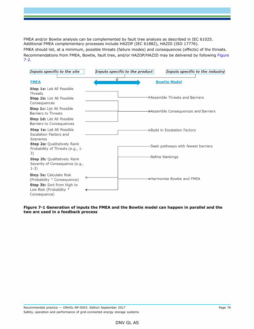
Recommended practice — DNVGL-RP-0043. Edition September 2017 Page 76Safety, operation and performance of grid-connected energy storage systems
DNV GL AS
FMEA and/or Bowtie analysis can be complemented by fault tree analysis as described in IEC 61025.Additional FMEA complementary processes include HAZOP (IEC 61882), HAZID (ISO 17776).FMEA should list, at a minimum, possible threats (failure modes) and consequences (effects) of the threats.Recommendations from FMEA, Bowtie, fault tree, and/or HAZOP/HAZID may be delivered by following Figure7-2.
Figure 7-1 Generation of inputs the FMEA and the Bowtie model can happen in parallel and thetwo are used in a feedback process

Recommended practice — DNVGL-RP-0043. Edition September 2017 Page 77Safety, operation and performance of grid-connected energy storage systems
DNV GL AS
Figure 7-2 Process for generating recommendations from Bowtie and FMEA analyses
Guidance note:FMEA (or FMECA) is a useful tool for evaluation of risk, because it begins with high level issues and provides a path toward moredetailed analysis. The FMEA process is typically performed with group input which contains, at a minimum, the manufacturer ofthe EES system and the end user. A third party to coordinate the population of the FMEA table can be helpful as the third party canconsider the risks most important to the end user while also coordinating with practical limitations provided by the manufacturer ofthe ES system.Regarding FMEA:
— Qualitative ranking of the threats can be accomplished with generic ratings on a 1-3 scale, with 1 being low and 3 being highprobability.
— Qualitative ranking of the consequences can be similarly ranked on a 1-3 scale as an indication of severity.
— The relative risk of the threat-consequence relationship can be most generically determined by product of the threat(probability) ranking and the consequence (severity) ranking, i.e., risk = Probability(threat)*Severity(consequence).
Additional refinements on the FMEA can be performed by considering barriers, escalation factors, and barrier mitigating effectswhich enhance or diminish the rankings for the threat or consequence. Barrier effectiveness can also be ranked with the criteria ona 1-3 scale. Barrier effectiveness can be used to scale the risk calculation by calculating the number of barriers and their relativeeffectiveness at reducing the probability of a threat.Complementary tools, such as Bowtie analysis, can be used to enhance and further refine the qualitative ranking defined by FMEA(Figure 7-1).
---e-n-d---o-f---g-u-i-d-a-n-c-e---n-o-t-e---

Recommended practice — DNVGL-RP-0043. Edition September 2017 Page 78Safety, operation and performance of grid-connected energy storage systems
DNV GL AS
7.3 Hazards, failure modes and effectsFor each EES system the potential safety issues should be evaluated and the hazards associated with each ofthose issues should be mitigated in the design of the ESS and construction of the installation in addition toensuring the requisite guidance for addressing any safety related incidents is available to those operating theEES as well as first responders who might be brought on site to address an EES incident.The major hazards for large-scale EES systems can be categorised as electrical, mechanical and otherhazards. Electrical hazards occur when there is a live contact between a person and an EES system exposingthe person to severe electric shocks. Mechanical hazards occur when there is a (unforeseen) physical collisionbetween a person and an EES system. Potential other hazards (mainly related to electric and electrochemicalsystems) include:
— explosion hazards, caused by a rapid expansion of gases— fire hazards, arising from combustible materials used in the storage system— thermal hazards, due to the thermal properties of a system or its components— thermal runaway hazard, causing propagation of increasing temperatures, pressures, and fire towards
neighbouring cells.— chemical hazards, caused by (unforeseen) contact between a person and toxic, acidic, corrosive
components leaking from the EES system.
The risk of electrical shock at the system level should be mitigated by applying design rules regardingelectrical insulation (e.g. containment), by wearing adequate personnel protective equipment and byimposing operational instructions.The risk of mechanical shock at the system level should be mitigated by applying design rules regardingcontainment.The risk of other hazards at the system level should be mitigated by applying design rules regardingcontainment.To guarantee safe handling in general, the following recommendations should be adhered to in order toprevent exposure to abusive environmental conditions:
— the EES system or its components should not be opened or punctured, including during emergencyoperations
— the EES system or its components should not be left in places of high temperature— the EES system or its components should not be exposed to condensation and high humidity— contact with water should be avoided— the EES system or its components should not be submitted to excessive electrical stress.
7.4 Safety requirements - technology agnostic
7.4.1 RedundancyRedundancy should be utilized where necessary. Safe system shutdown should still be possible if onecomponent (switch, fuse, etc.) fails. Redundancy requirements permit the containment of failure evenif one safety system fails, i.e., there is no condition under which a single point of failure will defeat thesafety barriers of the system. Redundant information on faults should be applied, i.e. ensuring sufficientinformation usable for fault detection remains available in case of individual sensor faults, rather thanensuring redundancy of individual sensors.
7.4.2 Fail-safe operationFor fail-safe operations testing at the system level reference is made to IEC 61508-4 for relevant definitions,other sections of IEC 61508 for the safety concept and IEC-61511 for implementation of safety instrumentedprocesses.

Recommended practice — DNVGL-RP-0043. Edition September 2017 Page 79Safety, operation and performance of grid-connected energy storage systems
DNV GL AS
Whenever possible, systems should fail in such a way that there is no risk of release of contained energy inthe system after shutdown.If risk is reduced when the system is in fully discharged state, provisions should be made such that in caseof failure automated shutdown procedures include full EES discharge, provided that this does not add otherhazards. This requirement should not be applied to lithium ion batteries and LICs.In case of fail-safe operation of any system prone to thermal runaway – or even minor exothermic instability– these systems should be employed with passive containment methodologies to prevent cascading ofthermal runaway (heat transfer from cell to cell). This should include the use of insulating materials (suchas air, ceramics, or specialized coatings or heat absorbent materials), metals (to sustain high temperatureand conduct heat away from failing cells), or sufficient cell separation (to reduce cell-to-cell interaction duringfailure).
7.4.3 Protection philosophy, protection devicesEffective electrical protection of an energy storage system requires both hardware and software protectionsystems.Hardware fault protection provides the baseline of system electrical safeguarding. The principal device in thisregard consists of over-current protection in the main current path of the battery, such as breakers or fuses.An additional level of safety is recommended by also integrating these elements within the battery systemitself. These are sometimes contained within cells, commonly in the form of Current Interrupt Devices (CID),but are ideally also implemented in battery power cabling between cells or modules. Hardware protectionshould also consist of protection from power supply under-voltage and over-temperature conditions, whichmay be achieved with insulated-gate bipolar transistors (IGBTs) or thermal fusing. The system should alsoprovide protection from ground faults as well as offer sufficient ingress protection for applicable components.Safety markers and information should be displayed wherever relevant.Software protection systems provide more comprehensive electronic system protection. A fundamentalaspect of software protection systems is the ability to shut down the converter and BMS before AC or DCcontactors are opened to isolate systems from detected risks. Software protection systems should consist ofBMS or EMS controlled identification and protection from such risks as, but not limited to:
— DC overvoltage protection— DC current protection— AC current protection— overtemperature protection.
AC voltage and frequency protection should also be provided, with recommended guidance from IEEEstandard 1547.
7.4.4 Enclosed spacesPrior to entry to an EES system in an enclosed space, the following hazards related to operation in enclosedspaces should be identified and the risks should be assessed. These procedures should be applied consideringthe volume of the enclosed space and whether there is a scenario of normal operation or of fire:
1) Assess the potential volumes of all gases released, and assign lower flammability limits and lowerexposure or toxicity threshold limits for each. The ventilation of the room will be determined by thelowest limit of all gases. Appropriate sensors should be selected to detect the most hazardous gases.
2) Determine if pressure is a consideration in the room. Pressure may be as a result of high rate emissions,or may be the result of explosive events due to the gases generated. The mechanical integrity of theroom should be compared to this pressure hazard.
3) Concentrations of gases as a function of enclosures should be calculated. This assessment shouldaccount for non-uniform allocation of volume within the space, such as rooms with separate doors,sub-compartments, or enclosures around the EES system. A risk assessment of the potential of gassesto reach critical concentrations in discrete zones should be performed, such that zone ventilationrequirements may be considered.

Recommended practice — DNVGL-RP-0043. Edition September 2017 Page 80Safety, operation and performance of grid-connected energy storage systems
DNV GL AS
4) Ventilation considerations should be addressed for the enclosed space as a whole (as in #1) as well assub-compartments (in #3). Again, the lowest concentration threshold will determine the ventilationrequirements. Ventilation should not prevent the function of sensors necessary to detect hazardousgases.
5) The ventilation system should be controlled in conjunction with the fire suppression system. In this way,ventilation control can be used to support the fire suppression system, or to keep escape routes clear ofsmoke.
6) Thermal loads as a function of maximum heat generated should be calculated as a function of distancefrom the heat source. Appropriate heat and fire rating of materials should correspond to these thermalloads. Appropriate cooling devices should accommodate maximum heat loads where applicable, andredundancy of these cooling devices should be incorporated if major safety functions are dependent oncooling.
7) Explosion hazards should be calculated as a function of volume and gas concentration in all sub-compartments of the enclosed space. The risk of projectiles, debris, and thrown objects should beestimated.
Guidance note:An enclosed space is an area with limited space and accessibility. Hazards in an enclosed space often include harmful dust orgases, asphyxiation, submersion in liquids, electrocution, or entrapment. The limited accessibility to enclosed spaces increases theseverity of the corresponding hazards.
---e-n-d---o-f---g-u-i-d-a-n-c-e---n-o-t-e---
7.4.5 First responders and fire considerationsAs early as possibly in an EES system project, at least before commissioning an EES system, first respondersshould be informed, involved to discuss FMEA/risk analysis results, agreed with on dedicated approachstrategies.Assessments should be performed to quantify what gases are released in a fire, what potential hazardousgases are generated in a fire, what other volatiles are released, what inhalation hazards may exist, whatextinguisher is most effective at suppressing the fire, and what potential secondary gases or residues may begenerated from the use of that extinguisher.Extinguisher considerations should include, at a minimum:
— most effective heat removal agent— minimal secondary gas or residue hazards due to extinguisher selection
Because water as an extinguisher is commonplace, the appropriate use of water as an extinguishing mediumshould be assessed, i.e. whether water reacts with the chemistries present or whether it is not an appropriateextinguisher class.If unconventional fire extinguishers are required, local first responders should be alerted and trained on theiruse. The appropriate and most suitable extinguisher should be recommended based on the specific needs ofthe site. This may include water in some cases and in all scenarios its use should not be discouraged.If an EES system is enclosed, a means to connect water extinguishers to the exterior in order to activateinterior sprinkler heads may be a requirement. First responders should be trained on this procedure. This isonly applicable if water is deemed as an appropriate extinguisher.Hazards after a fire should be identified at the time of installation such that recommendations for PPE areavailable for clean-up crews and hazardous materials (HAZMAT) teams. This may include respirators toprotect personnel from toxic gas that continues to be generated from hot cells. Firewater retention andcleanup measures may be required by local regulations.In addition to the gas generation risk, cells that remain hot also pose a delayed ignition risk, whereby heat inthe cell may transfer to undamaged adjacent cells or remaining active material and reignite the fire.Appropriate smoke or gas detectors should be employed in the building environment to accommodate specialcase fire hazards.

Recommended practice — DNVGL-RP-0043. Edition September 2017 Page 81Safety, operation and performance of grid-connected energy storage systems
DNV GL AS
Automated fire suppression systems should adequately suppress incipient non-battery fires in the batterycompartment, as well as manage any heat generated by battery system components.Lower flammability limits (LFL), and threshold exposure limits (TEL) of gases should be quantified forenclosed spaces.Appropriate considerations for exothermic heat loads from battery fires should be quantified for indoor andoccupied spaces.
Guidance note:Currently, the most effective heat removal agent has been found to be water, with water-based agents almost as effective at heatremoval, but showing no benefits over water.Because of the deep-seated nature of Li-ion battery fires and the dense packing of the cells, it is possible for cells that are nolonger burning to stay hot for hours after a fire. As long as lithium ion batteries stay hot, they continue to generate CO andhydrogen gas.Standards applying to Li-ion battery fires are currently under development, which should take into account 1) the hazards ofgases released if a battery is fully engulfed in a fire, 2) the toxicity of secondary gases generated in enclosed spaces as a result ofextinguishing, and 3) the variations by chemistry.For more information, including detailed test results of several energy storage technologies and analysis, reference is made to thereport Considerations for ESS Fire Safety, public report for Consolidated Edison, DNV GL (2017).
---e-n-d---o-f---g-u-i-d-a-n-c-e---n-o-t-e---
7.4.6 Thermal managementThermal management considerations should be made for
— normal operation— fire conditions (both those originating from the ESS itself as well as those associated with conditions
external to the ESS).
Indoor considerations for thermal management should include increases or changes in the fire rating forwalls, ceilings, structures, and doors. Based on testing, such walls should have a fire rating of at least twohours, for EES systems in occupied structures. 3
Ventilation, cooling, and suppression needs for indoor applications should require upgrades if the EES systemgenerates excessive heat or creates a fire load beyond the room’s designed suppression system.The maximum possible heat generated by the system in the event of the fire (particularly for chemistries thatare exothermic during failure) should be calculated and the impact on containers, enclosures, or surroundingrooms should be estimated. Attention should be paid to coming standards pertaining to maximum allowablequantities (MAQs) in these cases.For cooling considerations in fire management, it may be considered to match the maximum cooling loadwith the cooling medium available, i.e., if a fire hose valve has a flow rating of a certain number of liters perminute and the maximum cooling load requires a higher liters per minute rating, either the fire hose valveshall be upgraded or the EES system should be downsized to meet the safety requirement.Appropriate extinguishers should be evaluated not only for their ability to extinguish the fire, but also providecooling to the fire source.
3 Considerations for ESS Fire Safety, public report for Consolidated Edison, DNV GL (2017)

Recommended practice — DNVGL-RP-0043. Edition September 2017 Page 82Safety, operation and performance of grid-connected energy storage systems
DNV GL AS
Guidance note:In the US, the National Highway Traffic Safety Administration (NHTSA) has adopted the phrase “copious amounts of water” in itsrecommendations for fire extinguishing for hybrid electric vehicles (HEVs), plug-in electric vehicles (PEVs) and electric vehicles(EVs). As part of a knowledge sharing program, the NHTSA has offered classroom training to fire professionals with the US NationalFire Protection Agency (NFPA) who has adopted the same language. There is a risk associated with this language.
— Water does not prevent the formation of flammable and toxic gases during extinguishing: as long as the batteries stay hot,they will continue to generate those gases
— In the event of a small fire, first responders may proceed to the use of “copious amounts of water” even when such a practiceis not necessary, leading to significant collateral damage of the EES system.
---e-n-d---o-f---g-u-i-d-a-n-c-e---n-o-t-e---
7.4.7 Gas treatmentIf the EES system may generate uncombusted flammable gases before or during the fire, the risk ofventilation should be evaluated, i.e., whether continued ventilation increases severity of the fire to a greaterrisk than it prevents the build-up of flammable gases to an explosive limit.In enclosed spaces, ventilation should be terminated in the event of a fire in order to prevent the supply ofoxygen to the fire.If multiple flammable gases are emitted, the lowest acceptable level of toxicity or flammability limit shoulddictate the ventilation requirement.Residues from gases should be considered if their emission is intermittent, such that false positives fromsensors are not registered after an event has occurred.Sensors or detection media should be able to distinguish gases from one another, i.e. they should have highselectivity if the hazard of gases is significantly different. For example, if one gas is highly toxic and anotheris highly flammable, and a sensor with low selectivity can detect both, the sensor alarm will not be able toinform stakeholders whether the hazard is toxic or flammable, which provides no actionable information tofirst responders.
Guidance note:For example, Li-ion batteries employing ethylene carbonate based electrolyte solvents may off-gas to a lower flammability limit of3.6% by volume, compared to the LFL of H2 which is 4% by volume. The rate of emission, total quantity, room size, and ventilationcharacteristics will determine which LFL can be reached first. Of important note is that for a mixture of flammable gases, theoverall flammability lowers and the air may become flammable despite each gas present being well below its flammability limits.Besides ethylene, a range of flammable hydrocarbons, as well as H2 and CO, are released. These includes methane, ethane,benzene, etc.
---e-n-d---o-f---g-u-i-d-a-n-c-e---n-o-t-e---
7.4.8 Safety-relevant software, controls, BMS and communicationsSystem level tests and FATs should involve functionality tests to determine if system controls are capableof preventing catastrophic failure, or steering the system clear of conditions which increase the probabilityof catastrophic failure. For each software update during operation that may affect the system, the update’simpact on system safety and functionality should be assessed.For relevant FAT-related standards, reference is made to IEEE 1547, EN 50272, IEC 62485, IEEE 1375, IEEE1184, EN 50438, UL 1741, UL 1998 and UL 1973.For more general system level requirements, reference is made to IEC 60529.
7.4.9 Cyber securityPrecautions against unauthorized access to data and controls should be taken. Any software that has networkaccess, security software and the data infrastructure should be continuously monitored and kept up-to-date,in order to stay defensive against the latest cyber threats.

Recommended practice — DNVGL-RP-0043. Edition September 2017 Page 83Safety, operation and performance of grid-connected energy storage systems
DNV GL AS
For increased cyber security, three levels of connectivity of the EES system to the outside world may beconsidered: bidirectional connection, unidirectional connection (outward) and no connection, in order ofincreasing security. It may be considered to only allow EES system devices (e.g. BMS, converter, etc.) toconnect the internet after they are disconnected from the EES system, so not while they are in operation.
Guidance note:Inclusion of a system in any data exchange system will unavoidably expose it to malevolent access attempts. A data exchangesystem is not only a temporary or permanent connection to a larger computer network, but it can also include point-to pointconnections using a modem or a dedicated line, or data exchange using mobile storage media. Such malevolent access attemptscould include every aspect of cybercrime, of which the scope far exceeds gaining unauthorized control of the storage functionality.For example, systems are often hacked in order to serve as a platform for further criminal activities, a role which modern controlcomputers are easily capable of. In addition, even air gapped systems may be compromised if access to interfaces, including USB,serial and others, are not properly protected.
---e-n-d---o-f---g-u-i-d-a-n-c-e---n-o-t-e---
7.4.9.1 Cyber security requirementsThe following security requirements should be addressed for ESS devices:User access control
— Controlled access— User authentication and authorization— User account management— Role based access control— Password complexity
Secure communication
— Web server (https)— Remote connections (SSH)— VPN function— Secure protocols (IEC 60870-5-104 (IEC 62351-3/TLS)
Network control
— Firewall functionality— Network access control (authentication)— Electronic security perimeter— Remote access management— Segregation and boundary defence
Device and system control
— Change management— System hardening— (Security) Patch management— Backup and recovering— Malicious software prevention
Monitoring
— Local logging— External logging of events— Logging of user access and accounts— Logging of changes
Assessment
— Risk assessment— Security validation

Recommended practice — DNVGL-RP-0043. Edition September 2017 Page 84Safety, operation and performance of grid-connected energy storage systems
DNV GL AS
— Penetration testing
Awareness programs should be implemented to take cyber security seriously and to secure the appropriatefocus to cyber security in all phases.
Guidance note:Focus on cyber security is lacking. In order to embed cyber security within the lifecycle of the EES system, it is required to beaware what are the risks and what is required to focus on. To effectively manage cyber security risks it is required to understandthe EES system, grid processes, impact and risks.EES systems in operation support the grid with a variety of functionalities. Depending on the size in megawatts, the influence onthe grid could be significant. Inverters, which are commonly used within these systems, are capable to exchange power with thegrid in a very fast manner (depending on the size) regardless of the state of the grid. With these system characteristics, the EESsystem is able to endanger the grid in case of wrong control decisions due to operator failure or cyber-attack for example. Evenwhen EES systems are small, attackers could combine multiple systems to create the necessary impact to the grid. These attackvectors are endless and hackers are very creative creating new ones.Therefore, designing, implementing and operating EES systems comes with a certain responsibility. This responsibility is dealingwith the risk to a blackout of the grid using EES systems and needs to be considered in every phase of the lifecycle. The impact ofa blackout is significant. Supply of electrical energy is defined as vital infrastructure. This responsibility starts with the design ofthe EES system.EES systems are part of a larger electricity grid. Therefore, the systems need to deal with threats that comes along with thesupply of energy. Especially state-sponsored hackers and cyber terrorists explores possibilities to disrupt countries. Attacking vitalinfrastructures will be part of this exploration. Due to the increasing automation landscape, generic IT, IoT and interconnectionsthis becomes an increasing risk. While these hackers have all the resources and time in the world, they will eventually findweaknesses in the systems. The race to stay secure at one hand and the hackers on the other hand, is not an equal playingfield and will be eventually lost. One aspect is that these systems are difficult to be patched due to the availability requirements.Another aspect is that these systems are possibly not able to meet the security requirements over their full lifetime of 15 years, asthese will be significantly changed.If the complexity or security of a storage monitoring system or its access remote security do not allow live monitoring the ESSsystem to its full extend. Creating off-line agreements and procedures might be required to ensure the stakeholders still getregular data access.
---e-n-d---o-f---g-u-i-d-a-n-c-e---n-o-t-e---
7.4.9.2 Lifecycle testingCyber security testing should be an integral part of the EES lifecycle and all new systems should be testedfully before deployment. Cyber security tests examples are
— architecture review— device review— vulnerability scanning— penetration testing— robustness testing.
Cyber security testing should at least be part of:
— FAT; determine that the systems have been built securely and do the security features correctlyfunctioning as expected.
— SAT; determine that the systems are securely deployed and integrated.— Operation; ensure continuous secure operation by monitoring, risk assessment and patching.
7.4.9.3 System hardeningA process should be created and put in place to ensure continuous hardening of the EES system byperiodically performing a reality check. The principle of hardening is making sure that the attack surface toyour device is limited by:
— Only necessary network service ports should be open, others should be closed— Only necessary software should be installed on the device, other software should be removed— Development environments and source code should not be installed on production devices

Recommended practice — DNVGL-RP-0043. Edition September 2017 Page 85Safety, operation and performance of grid-connected energy storage systems
DNV GL AS
— Remote access protocols that use plain text communication should not be used— Software that stores passwords unencrypted should not be used
Guidance note:Even though system hardening seems to be obvious, most of the time it is forgotten. Insufficiently hardened systems exposea larger unwanted attack surface. It has been analysed that 97% of the breaches could have been prevented by simple orintermediate controls (source: Verizon DBIR 2012).If the EES system is connected to the internet, try to find it using the IoT search engine Shodan.
---e-n-d---o-f---g-u-i-d-a-n-c-e---n-o-t-e---
7.4.9.4 Incident responseTo respond appropriately to security incidents, the following should be defined: processes, communicationand dedicated teams for this job. Operators should be in the lead, while engineers and suppliers shoulddeliver support to find the problem and restore the system. Operators should prepare for responses to thistype of incidents.
Guidance note:Cyber-attacks are not new and utilized within warfare since the first oil pipe line automation has been implemented. However,in recent years a significant increase is seen on industrial control systems, like the energy industry. In 2015, around 50% of theincidents that have been reported by the US targeted industrial control systems.Stuxnet, seen as the first cyber weapon, attacked the uranium enrichment at Natanz. Attacked the centrifuges by fluctuate theirspeed and showed the operators that everything was functioning correctly. On December 23th 2015, the Ukraine power grid cyber-attack took place and successfully compromised three energy distribution companies. An advanced attack that showed a goodcoordination and utilized multiple attack vectors. By switching off 30 substations, around 230 thousand people had no electricityfor a period of 1 to 6 hours. It is currently considered the first known successful cyber-attack on a power grid.The operational team is responsible for the operation of the ESS system. Therefore, they will be the first ones who detect andperform the first actions in case of a security breach. Monitoring systems for industrial control systems will play a crucial role toenable operators to identify security breaches. Most monitoring systems in the market still require a level of IT knowledge.<https://ics-cert.us-cert.gov/sites/default/files/Annual_Reports/Year_in_Review_FY2015_Final_S508C.pdf>
---e-n-d---o-f---g-u-i-d-a-n-c-e---n-o-t-e---
7.4.10 Health and safety - considerationsIt is recommended to provide safety data sheets (SDS) to local first responders and stakeholders. In somecases, suppliers will provide material safety data sheets (MSDS) instead of SDS. They may be relevant butit should be taken into account that MSDS sheets are meant for chemicals that the environment can beexposed to, which is not the case in most EES since they contain sealed components.Ventilation should not contaminate fresh air supplies to occupied spaces.Spill management should not contaminate freshwater drain pathways.Disposal of hazardous materials should comply with local and national rules and regulations.
7.4.11 Safety with human interaction and general public safetyFor personnel qualifications during installation and maintenance of stationary batteries, reference is made toIEEE 1657.For safety requirements related to electrical shock, reference is made to NFPA 70 (in the US) and/or IEC61000-4.For non-permitted outlines, reference is made to the NEC Article 368.12.For specifications to prevent electrical hazards via containment and system protection, reference is made toingress protection code IEC 60529 depending on the specifics of the installation.Assessment of toxicity hazards due to fire should be considered such that plume and indoor gasconcentrations are addressed.
Recommended practice — DNVGL-RP-0043. Edition September 2017 Page 86Safety, operation and performance of grid-connected energy storage systems
DNV GL AS
For outdoor systems, proximity to populated areas should include a hazard assessment of potential gasesgenerated or explosion potential during a fire.Operators should receive special training for working with large EES systems.
7.4.12 Operator certification and training requirementsOperator personnel should receive a supplier- / manufacturer-approved training on the specific characteristicsof the EES (e.g. batteries should not be short-circuited). Applicable common standards (e.g. on electricalsafety) should be taken into account.A service manual which contains comprehensive information for carrying out maintenance activities shouldbe provided for maintenance personnel. The service manual should provide EES-specific safety instructionswhich exceed common safety rules.A local subject matter expert (SME) should be available in cases where substantial numbers of EES systemsexist. This person should be readily available to first responders in the case of emergency situations. If thisis not practical, a toll-free phone number should be available such that first responders may call and givenoperational data on the system, including its current state, and advise on how to proceed with the event.
7.4.13 Location-specific – residential, commercial and industrial or utilityThe risk assessment should take into account location-specific safety aspects of stationary EES system.For EES systems in residential applications the following hazards should be considered in the riskassessment:
— access by non-trained people— in case of explosion, release of toxic fluids and/or fire: exposure to a residential area.
For EES systems in commercial and industrial applications the following hazard should be considered in therisk assessment:
— in case of explosion, release of toxic fluids and/or fire: exposure to a commercial and industrialapplications.
For EES systems in utility applications the following hazard should be considered in the risk assessment:
— in case of explosion, release of toxic fluids and/or fire: exposure to the environmentGuidance note:EES systems may be applied for different applications, for example in residential, commercial and industrial and utility applications.Depending on the application the impact of a safety hazards may be different. This should be considered during risk assessments.EES systems for residential applications are typically small-scale installations located close to or inside the residence. Therefore,there is the potential hazard of non-trained people accessing such systems. In case of system failure, there is the hazard related toexposure to a residential area.EES systems for commercial and industrial applications are typically large-scale installations installed at large premises. Therefore,such systems are not easily accessible by non-trained people. In case of system failure, there is the hazard related to exposure tothe commercial and industrial applications.EES systems for utility applications are typically very large-scale installations installed at remote locations. Therefore, suchsystems are not easily accessible by non-trained people. In case of system failure there is a potential hazard related to exposurefrom system to environment due to the size of the system.
---e-n-d---o-f---g-u-i-d-a-n-c-e---n-o-t-e---

Recommended practice — DNVGL-RP-0043. Edition September 2017 Page 87Safety, operation and performance of grid-connected energy storage systems
DNV GL AS
7.5 Safety requirements - technology specific
7.5.1 Safety requirements for batteries7.5.1.1 GeneralIn the risk assessment of battery systems, attention should be paid to the fact that safety issues mayoriginate at the cell level, but may also arise at (sub) system level or may arise from the surroundingenvironment. Moreover, safety issues at the cell level may propagate and amplify towards the system level.Today, most standards address the issue of safety on cell level, and only few standards address the issue ofsafety at system level. Note that when safety is addressed at the cell or battery level there are a numberof other issues such as fire suppression, ventilation, access for working space, markings, etc. that shouldbe addressed separately. When addressed at the system level, through a standard or guideline covering anentire system those issues would be addressed through the conformity assessment activities associated withthe standard or guideline.Standards related to battery storage for stationary applications draw heavily on established technologiessuch as lead acid batteries. However, today’s stationary battery energy storage market is dominated by Li-ion technologies. Thus, there is a need to translate abuse vectors from prior Pb-acid experience to Li-ionexperience. In some cases, abuse testing may be selective in order to capture the most relevant failuremodes for other technologies.For safety and abuse tests of battery systems, see Table 7-1 showing the overlap across numerousstandards.

Recommended practice — DNVGL-RP-0043. Edition September 2017 Page 88Safety, operation and performance of grid-connected energy storage systems
DNV GL AS
Table 7-1 Safety and abuse testing standards and overlap
General remarks:
— For endurance tests, see Sec.5 ´Performance indicators´, since such tests are related to batteryperformance.
— For safety issues regarding shipping, transport, and movement activities of batteries, reference is made toIEC 62281, which is derived from UN38.3.
— For electrical shock testing for all battery systems, reference is made to IEC 62485-2, section 4.— For provisions against short circuits for all battery systems, reference is made to IEC 62485-2, section 6.— For provisions against explosions for all battery systems, reference is made to IEC 62485-2, section 7.— For individual lithium ion cells to be used in larger products, including EES systems, reference is made to
UL 1642.— For EES systems at the module level or higher, including full systems, reference is made to UL 1973 for
batteries and UL 9540 for systems.— For electrostatic discharge, radiated immunity, EFT, surge immunity, and conducted immunity, reference is
made to IEC 61000-4.

Recommended practice — DNVGL-RP-0043. Edition September 2017 Page 89Safety, operation and performance of grid-connected energy storage systems
DNV GL AS
— For non-permitted outlines, reference is made to the NFPA 70, National Electric Code (NEC,) Article368.12 (Busways: uses not permitted).
— For EES reference is made to Article 706 of the NEC.— For specifications to prevent electrical hazards via containment and system protection, reference is made
to ingress protection code IEC 60529.— The EES system should contain components which are in compliance with the EC Regulation 1907/2006
(REACH) and directive 2011/65 (ROHS).— The Management System of Energy Storage Systems usually contains control functions and safety
functions. The safety functions should be redundant to prevent further propagation of failures.Redundancy of the safety functions should be obtained by both technical solutions, such as fuses, circuitbreakers and mechanical disconnectors; and by control solutions, such as management systems at alllevels of the energy storage systems.
— For safety tests regarding the (battery) management systems reference is made to IEC 62619 and DNVSFC No 2.4.
— Operation of the energy storage systems should be conditioned in order to guarantee appropriatetemperature, humidity and (electro-magnetic) radiation. The operational conditions should be determinedby the cell or module manufacturer.
7.5.1.2 Technology-specific – Lead-acid batteriesFor lead acid batteries, reference is made to IEEE 450.For lead acid cells in stationary industrial applications, reference is made to IEEE 1188 and IEC 60896.For installation of lead acid battery systems in stationary industrial applications, reference is made to IEEE484.For personnel safety requirements regarding lead acid and nickel cadmium battery systems, reference ismade to IEEE 1657.For island operation of lead acid battery systems in combination with renewable energy sources, reference ismade to IEC 62257.Fires related to lead acid batteries should be extinguished with CO2 or dry chemical methods. Water may beused in emergency situations where runoff may be managed.Appropriate ventilation should be incorporated to manage potential off-gassing or evaporated electrolyte.Whenever possible, detection or monitoring equipment should be considered for off-gases which may alsobe incorporated into emergency shut-down or extinguishing capability. For managing off-gasses under fireconditions, there is no dedicated standard. For ventilation of lead-acid off-gasses (e.g. hydrogen), referenceis made to IEC 62040 and EN 50272-2.

Recommended practice — DNVGL-RP-0043. Edition September 2017 Page 90Safety, operation and performance of grid-connected energy storage systems
DNV GL AS
Guidance note:Most standards for lead acid batteries refer to IEEE 450 (Recommended Practice for Maintenance, Testing, and Replacement ofVented Lead Acid Batteries for Stationary Applications). This standard deals with performance of lead acid battery systems instationary industrial applications. It contains procedures for installation, operation, maintenance and inspection.Based on the IEEE 450 standard for the safety risks of lead acid batteries, the following list items state recommendations to befollowed in lead acid applications:
— Emission of hydrogen off-gas in enclosed environments should be safeguarded by adequate monitoring and ventilation.
— Degradation of the SOH can be slowed down by keeping the battery fully charged as much as possible.
— The state of health should be monitored by capacity and discharge tests at a monitoring frequency that does not negativelyimpact the battery’s state of health
— The potential risk of thermal runaway should be safeguarded by overcharge protection.
— The risk of evaporation of electrolyte should be safeguarded by monitoring of electrolyte.
For lead acid batteries, the following hazards are identified:
— Lead acid batteries contain electrolyte consisting of dilute sulphuric acid, which may cause severe chemical burns.
— Lead acid batteries may develop hydrogen gas and oxygen during charging or operation, which under certain circumstancesmay result in an explosive mixture.
— In a fire, evaporation or boiling of the electrolyte can lead to sulphuric acid gas and other sulphur-based compounds.
Temperatures between 325-337°C pose the risk of evolved sulphur-based gases from the electrolyte, atomization of dissolvedPb and lead oxides, and molten Pb. Lead boils at 1750°C, which is above the expected temperatures in a fire in a commercialor residential environment. The more immediate concern is the potential generation of SO2 which is immediately dangerous tolife and health (IDLH) at only 100 ppm and has an NFPA Health Rating of 3. By comparison, the carbon monoxide (CO) IDLHthreshold, for example, is 1200 ppm.Lead crystal batteries are a sub-type of lead acid batteries which exhibit significantly differently behaviour in some respects. Leadcrystal batteries contain a microporous super absorbent matt, thick plates cast from high purity lead calcium selenium alloy, and aSiO2 based electrolyte solution. During the initial charge / discharge cycles the electrolyte solidifies leaving hardly any free liquidelectrolyte in the battery and thus improving the reaction ability between the electrolyte and active material on the lead plates.This results in a battery with extended cycle life. Furthermore, deep-discharge behaviour is good, lower amounts of heavy metals(e.g. Cd, Sb) offer environmental benefits and performance (e.g. C-rate) is good in a wide operating temperature range.The safety risks for lead crystal batteries are potentially lower in the following areas:
— Leakage: the cells are sealed; in case of cell damage the electrolyte is spilled as an easy-to-handle powder
— Effects of exposure to leakage: the electrolyte of lead crystal acid batteries contains significantly less sulphuric acid
— Explosion: during charging or operation, significantly smaller amounts of explosive gases are produced
— Transportation: lead crystal batteries are classified as non-hazardous goods; there are no regulations for (air)transport.
---e-n-d---o-f---g-u-i-d-a-n-c-e---n-o-t-e---
7.5.1.3 Technology-specific – Li-ion batteriesFor abuse testing of Li-ion batteries, reference is made to IEC 62660-02.Adequate cooling and management of temperature excursions should be primary considerations in the designand implementation of a Li-ion battery. Consideration of off gases, their routing and management, shouldalso be a primary concern.In most cases, the temperature of Li-ion batteries should not be higher than 70°C to prevent thermalrunaway, unless explicitly approved by the EES manufacturer.The temperature of Li-ion batteries should not go below 0°C (unless manufacturer specified) to prevent Li-plating, which may result in internal shorts. As some Li-ion chemistries are more sensitive than others to coldtemperatures, manufacturer specifications should be checked for specific limitations. For cold discharge testsreference is made to UL 1642, or IEC 62660-2.Appropriate ventilation should be incorporated to manage potential off-gassing or evaporated electrolyte.In the case of larger batteries, monitoring of the lower explosive/flammable limit (LEL) of the air may benecessary. Whenever possible, detection or monitoring equipment should be considered for off-gases whichmay also be incorporated into emergency shut-down or extinguishing capability. For ventilation of Li-ionbatteries, reference is made to IEC 62485-2.

Recommended practice — DNVGL-RP-0043. Edition September 2017 Page 91Safety, operation and performance of grid-connected energy storage systems
DNV GL AS
In the design of the battery system, special attention should be given to the choice of anode-cathodechemistry with respect to the system specifications, since different chemistries have different reactivity andthermal stability. Though thermal stability and volatility may vary, all lithium ion batteries are flammablewhen exposed to fire.For safety tests regarding the (battery) management systems of Li-ion battery systems reference is made toIEC 62619.Thermal separation or insulation should permit the burning of a single cell to conclude without causingadditional cells to fail, even if extinguishers fail to actuate, mitigating the risk that a single cell failuretriggers automated extinguishers. Sufficient cascading protection should be implemented as one of the mostimportant passive design features of an EES.The safety risk of large scale and cascading thermal runaway should be managed with appropriatecontainment, thermal management systems, extinguishing and isolation procedures. Containment mayinclude active cooling, metal or ceramic plates, or heat absorbing materials.A Li-ion battery fire has the potential to evolve through all known fire classes. All of the precautions requiredat the local level should be considered during fire extinguisher and containment selection, including but notlimited to:
— cooling requirement— gases released within enclosed spaces— chemical reactions between extinguishers and burning materials— cascading protections in the system to limit fire propagation— external fire threats— incipient fire versus full system fire extinguishers— chemical contamination and collateral damage from non “clean agent” extinguishers— hazardous materials and cleanup— risks to building occupants and first responders, including gas generation from batteries after fires, as
batteries may continue to evolve CO and H2 long after the fire has been extinguished 4
Presently, there is no adequate extinguisher solution that addresses all aforementioned issuessimultaneously. Therefore, fire protection design may include multiple extinguishers, or a single extinguisherthat is admittedly a compromise.A common example of such a compromise that may be applied is using large volumes of water to ensurecooling, provided that water does not create further hazardous gas conditions, e.g. in a confined, occupiedspace. Precautions should be taken to prevent electrocution by water. Again, care should be taken to provideadequate cooling and monitor for gas generation during and after fire ground operations.SOC and SOH information should be available on the physical outside of the Li-ion system, for use by firedepartments and other helping hands.Reference is made to UL 9540 for design and implementation of system level EES safety measures.
4 Considerations for ESS Fire Safety, public report for Consolidated Edison, DNV GL (2017)

Recommended practice — DNVGL-RP-0043. Edition September 2017 Page 92Safety, operation and performance of grid-connected energy storage systems
DNV GL AS
Guidance note:The main identified risk for Li-ion batteries is related to the thermal stability of the cathode material combined with theflammability of the other cell constituents. Differences in sensitivity to thermal runaway or the amount of energy released duringan event exist between different technologies. For example, lithium titanate has a lower combustion value of the constituents, andLiFePO4 chemistries are reportedly less sensitive to thermal runaway due to a more stable cathode material. When the temperatureis above 70°C thermal runaway may occur. This may vary according to chemistry or cell construction and any provisions to lowerthe temperature sensitivity should be provided by the manufacturer to the local AHJ. Thermal runaway refers to a situation wherethe cell temperature reaches a threshold that causes an uncontrollable rapid release of energy. The corresponding temperaturerise results in a thermal event such as fire. Li-ion fires are a unique class of fire and may result in emissions of large volumes oftoxic gas and/or combustible gas causing huge fire(s). The majority of volatile organic content arises from the electrolyte solventsused in the battery, which are usually ethylene carbonate compounds. Most commercial Li-ion systems force a system shutdown atan upper temperature limit at 50°C in order to provide a safe margin of error. Some Li-ion chemistries may be more temperaturetolerant than others and this will be indicated in the battery specification documentation provided by the cell manufacturer.When the temperature is in the range between -5°C and -15°C, lithium plating can occur, which may result in internal shorts.Again, chemistry-specific considerations apply.Batteries containing lithium Cobalt Oxide (LiCoO2) cathodes are more reactive and have poorer thermal stability than batteriescontaining lithium iron phosphate or lithium nickel manganese cobalt (NMC or NCM) cathodes. That is because at elevatedtemperatures decomposition of LiCoO2 cathodes generates oxygen which will react with organic materials in the cell. Thisextremely exothermic reaction can also induce thermal runaway in adjacent cells or can ignite nearby combustible materials. Sincethe early 2000’s, many modifications have been performed to the basic LiCoO2 chemistry which may include NCM or LMO (lithiummanganese oxide) variants, which improve thermal stability.Most Li-ion batteries contain a flammable organic electrolyte and therefore their safety standards should be more stringent thanthose for acid-electrolyte batteries. In case of Li-ion batteries with inorganic electrolyte, the fire resistance is expected to be bettercompared to Li-ion batteries with organic electrolyte, since the electrolyte does not contain combustible materials. Still, also for Li-ion batteries with inorganic electrolyte the impact of released gases during fire should be considered (e.g. the toxicity of releasedgases generated in enclosed spaces; corrosiveness).Although most standards address the issue of safety on Li-ion cell level, only few standards address the issue of safety on Li-ionsystem level.Conducting abuse testing according to one of the standards mentioned can usually accommodate many of the requirements for theothers. However, certification against any one standard will require completion of that standard in its entirety.
---e-n-d---o-f---g-u-i-d-a-n-c-e---n-o-t-e---
7.5.1.4 Technology-specific – redox flow batteriesFor classification of electrolytes for redox flow batteries, reference is made to UN 1760 or UN 3260. Fortesting requirements, reference is made to UL1973.Training on personal protective equipment (PPE) should be provided, including self-contained breathingapparatus (SCBA). Classification of hazards to personnel should begin with the Safety Data Sheet (SDS),and these hazards should be incorporated into FMEA or Bowtie analysis to recommend spill and clean-upmanagement procedures.Appropriate ventilation should be incorporated to manage potential off-gassing or evaporated electrolyte.Whenever possible, detection or monitoring equipment should be considered for off-gases which may also beincorporated into emergency shut-down or extinguishing capability.Events should be avoided, which may alter the chemical composition or decrease the effectiveness ofcomplexing agents or other stabilizing additives, in order to prevent evolution of more volatile gases from theelectrolyte.Adequate protection from spillage of electrolytes should be considered, including system containment,vermiculite or other chemically active adsorbent or absorbent materials, spill trays, protection from tipping,and considerations for handling conductive electrolytes.Temperatures > 50 °C should be avoided for safe operation of Zn-Br batteries to avoid Br evaporation.In case of fail-safe operation, the BMS should shut down the pump. The design of the redox flow batteryshould guarantee gravity-driven draining off of the electrolyte.

Recommended practice — DNVGL-RP-0043. Edition September 2017 Page 93Safety, operation and performance of grid-connected energy storage systems
DNV GL AS
Guidance note:A redox flow battery consists of two tanks of electrolyte that exchange H+ ions through a proton exchange membrane. Thereactants are circulated through the cell stack as required.There are several types of redox flow batteries such as zinc-bromine, cerium-zinc, polysulfide bromide, and all-vanadium.The safety risks are related to the toxicity of the reagents and the acidity of the electrolyte. The hazard related to the release ofexplosive gases (oxy-hydrogen) may occur in some chemistries, while the hazard related to the release of toxic gases and liquids,or corrosive liquids may be more common and varies by chemistry.In addition, the hazard related to electrocution in case of redox flow batteries may be increased due to possible spilling ofconductive electrolyte.Zinc-bromine batteries use complexing agents to suppress the vapour pressure of bromine.
---e-n-d---o-f---g-u-i-d-a-n-c-e---n-o-t-e---
7.5.1.5 Technology-specific – copper-zinc batteriesAll generic safety considerations and measures applicable to battery EES systems also apply to copper-zincbattery ESS systems, such as chemical hazards, voltage and current hazards.
Guidance note:A copper-zinc battery consists of a tank containing the copper liquid electrolyte, into which cells are inserted vertically. Each cellconsists of a frame with a battery separator on one side and the bipolar electrode on the other. The bipolar electrode has zinc onone side and copper on the other. The zinc liquid electrolyte is in the void between the membrane and the electrode. Inserting anumber of cells into the tank means they are in series, so increasing the number of cells increases the energy storage capacity.
---e-n-d---o-f---g-u-i-d-a-n-c-e---n-o-t-e---
7.5.1.6 CellsSingle cells may or may not have embedded fuses or current interrupt devices. If fuses or CIDs are notincluded at the cell level, they should be included at the module or sub-module level in such a way that eachseries string is secured by at least one fuse. The fuse should be rated for the full system DC voltage.Whenever relevant, cells should have a mechanism for venting off-gases that are generated internallyas a means for pressure relief. These vents should encourage flameless venting or –in the worst case –deflagration, rather than explosion.Whenever possible, vents for cells should be aligned in the same direction such that ventilation can be routedefficiently around modules.If a thermal runaway risk is possible with the energy storage cell, appropriate use of thermal insulation andcooling should be considered.
7.5.1.7 Second life applications: safety issuesFor EES, second life may be described as reuse and repurposing of key EES components from one or moreprimary applications (including non-grid-connected applications such as electric vehicle batteries) in anotherapplication.The history of EES systems should be well documented to enable safe repurposing.For batteries, the following considerations apply:
— Safety evaluation of aged and new cells should be conducted for comparison in order to determinewhether the aged cells are at increased or decreased risk of failure.
— The safety of secondary batteries should be considered very carefully since the history of these batteriescould be partially or wholly unknown or uncertain.
— If the degradation of the batteries has significantly reduced energy, power, or capacity, then smart BMSsor controls should be incorporated in order to prevent overcharging or -discharging in the aged state.
— Cell or module balancing should be actively incorporated in systems employing second life batteries dueto the increased disparity in cell quality and capacity. For second life applications, the integrity of batterycells should be tested (for example detection of leaks).
— If new replacement components with non-original specifications are introduced into a system, the impactof the deviating specifications should be evaluated.
Recommended practice — DNVGL-RP-0043. Edition September 2017 Page 94Safety, operation and performance of grid-connected energy storage systems
DNV GL AS
For redox flow batteries, the following considerations apply:
— Second life of electrolyte may be considered.
For more considerations regarding repurposing of EES systems, reference is made to section [4.9.1].Guidance note:Ageing does not significantly affect system performance for mechanical storage systems. For battery systems, ageing manifestsitself as a gradual deterioration of system performance. The characteristics of battery systems deteriorate over time since they arebased on electrochemistry. In case battery systems or sub-systems (for example modules and/or cells) are no longer suitable fortheir dedicated application, they may be used in second life applications, which less stringent specifications. Combining batterycells and/or modules in new applications with different histories require additional safety evaluations.
---e-n-d---o-f---g-u-i-d-a-n-c-e---n-o-t-e---
7.5.2 Safety requirements for non-battery technologies7.5.2.1 Technology-specific – supercapacitors (electric double layer capacitors)For performance tests and safety considerations regarding supercapacitors, reference is made to UL 810A.For general electrical safety testing regarding supercapacitors, reference is made to IEC-62576.In addition, appropriate fans or cooling should be evaluated for supercapacitor-based EES system electronics,as temperatures from supporting electronics such as supervisory controllers, capacitor monitoring electronics,inverters and other circuit board based devices (not part of the supercapacitor cells or modules) may requirespecific board level cooling under certain circumstances. See [6.5.5] for monitoring and control safetyrecommendations applicable to supercapacitors.Supercapacitors may operate at higher temperatures than specified, and are likely to be operable attemperatures above the rated operating range for the balance of system electronics. Therefore, operationaltemperatures for supercapacitor based systems are likely to be driven by the electronics as opposed to thestorage technology, unlike for example lithium ion batteries.Though supercapacitors do not pose a thermal runaway risk like some lithium ion batteries, they containchemicals which are highly flammable by themselves. The flammability and volatility of the electrolytemay be substantially reduced by capturing the volatile chemicals within high surface area materials inthe cell, consequently reducing the amount of free electrolyte. Supercapacitors may burn when subjectto severe abuse conditions such as overvoltage, over temperature or puncture. During these events,the capacitors may vent, and the flammable gas may be ignited via other electronics. To that end, aneffective fire suppression system should be installed covering the entirety of the system, including powerelectronics, as well as detection and alarming systems when these systems are installed in occupied areasor in places where fire may pose a threat to life or property. Voltage monitoring should be present on everysupercapacitor cell and every module or series grouping of cells. Cell temperature should be monitored toavoid these abuse conditions.In addition, appropriate fans or cooling should be evaluated for supercapacitor-based EES system electronics,as temperatures from supporting electronics such as supervisory controllers, capacitor monitoring electronics,inverters and other circuit board based devices (not part of the supercapacitor cells or modules) may requirespecific board level cooling under certain circumstances.
Recommended practice — DNVGL-RP-0043. Edition September 2017 Page 95Safety, operation and performance of grid-connected energy storage systems
DNV GL AS
Guidance note:Supercapacitors (also known as ultracapacitors or electric double layer capacitors (EDLC) store and deliver energy at relativelyhigh rates (beyond those achievable with batteries) because the mechanism of energy storage is by charge separation (as inconventional electrolytic capacitors).Supercapacitors store charge electrostatically (non-Faradaic) by reversible adsorption of the electrolyte onto electrochemicallystable high surface area carbon electrodes. Charge separation occurs on polarization at the electrode/electrolyte interface,producing a double layer.Since charge storage is achieved at the surface of the high surface area carbon electrodes, supercapacitors can be charged anddischarged rapidly with >95% efficiency. Thus, cyclability of these devices is very high reaching millions of cycles under controlledvoltage and temperature conditions.Supercapacitors exhibit a sensitivity to voltage during overcharge on par with lithium ion batteries and may vent under extremecircumstances when overcharged. Certain supercapacitor manufacturers design and manufacture their devices to safely ventif operated under “abuse” conditions i.e. overvoltage and/or over-temperature. If supercapacitors are operated improperly,punctured or exposed to high temperatures (as may be encountered in a general fire situation) the adsorbed electrolyte mayescape and ignite from the external ignition source.Supercapacitors provide high currents, require no specific charging protocol and have long lifetimes (both in cycle life and calendarlife).As for all large-scale energy storage systems, fire detection and suppression should be evaluated with the manufacturer’sguidance.
---e-n-d---o-f---g-u-i-d-a-n-c-e---n-o-t-e---
7.5.2.2 Technology-specific – Li-ion capacitorsFor electrical characterization of LICs reference is made to IEC 62813.For protection against short circuits during transport, reference is made to UN3508 standard.Fire should be extinguished with carbon dioxide, dry chemicals or water. Although its risk and effects arelower compared to Li-ion batteries, the possibility of minor thermal propagation should still be taken intoaccount for both heat management and extinguishing measures.For safety tests regarding the (battery) management systems of Li-ion battery systems reference is made toIEC 62619.Appropriate ventilation should be incorporated to manage potential off-gassing or evaporated electrolyte.Whenever possible, detection or monitoring equipment should be considered for off-gases which may also beincorporated into emergency shut-down or extinguishing capability.
Guidance note:LICs are capacitors with a permanent electrical charge. They bridge the gap between Li-ion batteries and supercapacitors, offeringhigh energy and high power devices. They have a Li-doped graphite anode (like a Li-ion battery) and an activated carbon cathode(like a supercapacitor) and an electrolyte (similar to a Li-ion battery).LICs resemble Li-ion batteries in their operational voltage range, low self-discharge and since they cannot be fully discharged to 0V. LICs resemble supercapacitors since they provide high currents, they require no specific charging protocol and they have longlifetimes (both in cycle life and calendar life).LICs are considered to have a lower heat risk than Li-ion batteries, but the cells do need to be protected against overcharge andovertemperature, so appropriate thermal management is recommended for the event of fire.
---e-n-d---o-f---g-u-i-d-a-n-c-e---n-o-t-e---
7.5.2.3 Technology-specific – flywheelsFor safety considerations regarding installation and operation of flywheels, reference is made to IEC 60034-1Rotating Electrical Machines, which includes requirements for grounding and temperature limits of operation.For functional safety requirements of flywheels, reference is made to IEC 61508.For validation guidelines for certification reference is made to ISO 13849-1, which provides instructions formaking electric machines safer.Possible failure modes for flywheels include:
— mechanical failure of the flywheel or its components

Recommended practice — DNVGL-RP-0043. Edition September 2017 Page 96Safety, operation and performance of grid-connected energy storage systems
DNV GL AS
— malfunction of the bearing system— vacuum system— cooling.
All failure modes can lead to an immediate release of the energy stored with in the flywheel. Two implicationsresult:
— burst of the flywheel— transfer of the angular momentum from the flywheel to the substructure.
To mitigate the impact of these failures on the surrounding all flywheel designs utilize a containment. Thecontainment is designed in a way that now parts of the flywheel leave a defined safety area.Current safety validation testing involves burst testing to probe containment integrity, loss-of-vacuumtesting, overspeed testing, as well as fatigue testing of sample materials.Modern flywheels utilize instrumentation to detect changes in rotor operation in order and to stop operationbefore failure occurs.Unless otherwise specified by the manufacturer, absolutely no work should be conducted on a flywheel orwithin its safety area while energy is stored within the system.
7.5.2.4 Technology-specific – compressed air energy storageFor health and safety considerations regarding compressed air energy storage (CAES), a distinction is madebetween storage of compressed air in an above-ground energy storage vessel or an underground geologicalreservoir.For safety considerations regarding pressure vessel design, manufacturing, and operation reference is madeto IEC 11439, the ASME Boiler and Pressure Vessel Code (BPVC) and the Pressure Equipment Directive of theEU (PED). These standards regulate parameters such as maximum safe operating pressure and temperature,corrosion allowance, minimum design temperature and required safety factors (the load carrying capacity ofa system beyond the expected or actual loads).For storage in geological underground structures, distinction is made between different phases. In theinvestigation phase information on the underground, storage medium should be collected and analysedto determine the location with the highest potential to locate the caverns. In the exploration phase, testholes and subsequently boreholes should be drilled to collect and analyse the underground conditions todetermine the suitability of the medium for use as a storage vessel. At this point some key informationis gathered from analysis that should be carried out, such as mechanical integrity etc. In the design andconstruction phase, the above-ground storage vessel is designed or the salt based CAES vessel is solutionmined. During the commissioning and operation phase, the well should be tested and monitored for leakageand degradation. During the decommissioning phase, the underground structures should be managed inaccordance with the decommissioning process as set out by the Solution Mining Research Institute (SMRIhttp://www.solutionmining.org/).During all phases of product life, the storage system should be compliant with Industry, H&S and Designguidelines.
— For the design and construction of salt caverns reference is made to:
— EN 1918-3:2016. Gas infrastructure. Underground gas storage.— BSOR 2008. A guide to the Borehole sites and operations regulations 1995. HSE L72. Second edition.
ISBN: 9780717662876
— For the commissioning phase of salt caverns reference is made to:
— Crotogino, F., 1995. SMRI Reference for External Well Mechanical Integrity Testing / Performance, DataEvaluation and Assessment. SMRI Research Report No 95 -0001-S
— Van Sambeek, L, Bérest, P., Brouard, B., Improvements in Mechanical Integrity Tests for Solution-Mined Caverns Used for Mineral Production or Liquid-Product Storage. SMRI Research Report No 2005-
For the decommissioning phase of salt caverns, reference is made to Cavern Well Abandonment TechniquesGuidelines Manual. SMRI Research Report No. 2006-3-SMRI.
Recommended practice — DNVGL-RP-0043. Edition September 2017 Page 97Safety, operation and performance of grid-connected energy storage systems
DNV GL AS
For the power and ancillary equipment, compliance with the manufacturer’s guidelines for safe operation andwith national, regional and local regulations should be checked.For functional safety requirements of CAES, reference is made to IEC 61508 for electrical, electronic andprogrammable electronic safety related systems.In case of failure, the BMS should shut down the respective compressor or cryopump and generator.
Guidance note:Conventional CAES systems consist of an electric generation system and an above-ground energy storage vessel or anunderground geological reservoir. The main safety concern related to above-ground CAES pressure vessels is catastrophic tankrupture. Potential geological underground structures are salt stratas and domes, excavated mines, aquifers or depleted natural gasfields. There are currently two operational facilities in the world, and they are operating on solution mined salt caverns or vessels.A possible safety issue related to geological structures is the presence of residual hydrocarbons, which may in combination withthe presence of oxygen and heat result in combustion or detonation. This occurs when the mixture of hydrocarbons and oxygen iswithin the explosion limits.
---e-n-d---o-f---g-u-i-d-a-n-c-e---n-o-t-e---
7.5.2.5 Technology-specific – liquid air energy storageFor safety considerations regarding liquid air energy storage (LAES) systems, relevant standards should bebased on location. These are typical standards relevant to all electrical and spinning machinery, includingcompressors, as well as industrial noise and regulations for operating any gas or cryogenic plant. Also ofprime consideration is ASME B31.3, which applies to all process pipelines.The unit should also be subject to local welding codes, such as BS EN 15614 of the European Welding Code.A number of regional standards and directives may apply to the unit, including standards related to pressureequipment and spinning machinery, including compressors. These include BCGA, BCC, EIGA, AIGA, CGA, IECand NFPA 1 and 70 (for fire and electrical safety in the US).In case of failure, the BMS should shut down the respective compressor or cryopump and generator.
Guidance note:Conventional LAES systems consist of an electric compression system and a hot and cold temperature source.The main safety concern related to LAES pressure vessels is catastrophic tank failure or failure of a pressurized system. The liquidair is stored at near ambient pressure, so does not constitute a pressure risk unless the tank fails or the system fails during thecompression, cooling or heating stages.Liquid nitrogen and air are commonly stored products and significant industry experience exists for handling these fluids. Theunit should not release gas in sufficient quantities. The primary risks to human safety are frost and heat burns near the relevantprocess points.
---e-n-d---o-f---g-u-i-d-a-n-c-e---n-o-t-e---
7.6 Safety requirements for specific life cycle phasesDuring the risk assessment, the impact of the hazards should be considered for all stages of the life cycle(see Sec.4: design and planning, transport, installation and commissioning, operation, maintenance andrepair, EoL management). In general, the highest risk periods for the EES system are during transport,installation and commissioning, maintenance and repair. However, the existing standards do not distinguishbetween the different stages of the life cycle.
7.6.1 Transport and warehousing phase— The EES system should be stored in a cool, dry and atmospheric pressure area, away from combustibles.— Exposure to heat, sun light and ignition sources should be avoided.— For long term storage, it is recommended to store it between 0°C and 35°C.— The storage facility containing batteries should be able to withstand a fire for a minimum time. This may
be accomplished by installation or placement of fire rated walls. Based on testing, batteries should bestored in areas where walls should have a fire rating of at least two hours.
Recommended practice — DNVGL-RP-0043. Edition September 2017 Page 98Safety, operation and performance of grid-connected energy storage systems
DNV GL AS
— In the case of gas phase extinguishers (inert gases, clean agents or aerosolized agents), in EES systemswhere sufficient cascading protection has not been demonstrated, water based extinguishing systemsshould be used in addition or as backup.
— EES systems should be packed in such a way as to prevent short circuits under conditions normallyencountered in transport.
— For packaging boxes, strong materials should be used so that the EES system will not be damaged byvibration, impact, dropping, stacking and exposure to corrosive materials (e.g. seawater) during itstransport and warehousing.
— The package in which the EES system is transported or stored should be equipped with sensing provisionsfor tilt, acceleration (shock), vibration, temperature and humidity at any time between manufacturing andcommissioning, for all systems containing components sensitive to such factors, such as Li-ion modulesMitigating measures should be provided in case a sensor has registered excessive exposure, for examplechecking for traces of condensation in case relative humidity has been too high, or checking for cableducts to be intact after excessive vibration.
— Battery systems should be stored and transported at a technology-specific SOC value to minimise ageingprocesses as well as safety risks. For example, Li-ion batteries should be stored at around 50% SOCand lead acid batteries at about 100% SOC. The supplier should provide the appropriate SOC range forwarehousing and transportation.
— Redox flow systems can be stored and transported according to the regulations that apply to the storageand transport of the chemicals used, when both reservoirs are physically disconnected from the cell stackand adequately sealed.
— Electric and electrochemical EES systems should be considered as non-hazardous, but dangerous goodsfor transport.
— Electric and electrochemical EES systems should be packaged according to the specific requirementsdescribed by the UN Transport of Dangerous Goods regulations during transport.
— For Li-ion batteries, reference is made to section 38.3 of the UN Manual of Tests and Criteria (UNTransportation Testing) which is identical to IEC 62281. It is a legal requirement that the final systemdesign should be certified following this UN manual of test and criteria to be authorised for transport, andthe system should be labelled with the transport identification numbers UN3480 for batteries or UN3481for batteries contained in equipment. These constraints should be taken into account early on during theprocurement process due to impact on costs, time and risks.
— For road transport of Li-ion batteries reference is be made to the European Agreement concerning theInternational Carriage of Dangerous Goods by Road (ADR).
— For sea transport of Li-ion batteries reference is made to the International Maritime Dangerous Goods(IMDG) Code.
— For air transport of Li-ion batteries reference is made to the Transport of Dangerous Goods by air (IATADGR) regulation, published by The International Air Transport Association (IATA).
— For railway transport of Li-ion batteries reference is made to the International Carriage of DangerousGoods by Rail (RID) regulation.
— Transport regulations for lead-acid batteries depend on the battery type. UN2794 and UN2795 are thetransport identification numbers for flooded batteries with respectively acidic and alkaline electrolyte. Geltype or absorbent glass mat (AGM) lead-acid-batteries carry the UN2800 transport identification numbers.
— Transport regulations for LIC are defined in the UN model regulations under the category number UN3508.Depending on the size of the cells and the manufacturer, transport of LIC EES systems can possibly takeplace with very few requirements.
— Transport regulations for supercapacitors are defined in the UN model regulations under the categorynumber UN 3499. Supercapacitors should be regarded as not subject to dangerous goods (hazardousmaterials) transportation regulation and can be transported accordingly.
See [4.5]for more recommendations concerning this phase.

Recommended practice — DNVGL-RP-0043. Edition September 2017 Page 99Safety, operation and performance of grid-connected energy storage systems
DNV GL AS
7.6.2 Installation and commissioning phase— The EES system should be installed and commissioned by well-trained technicians since improper handling
may cause electrical shock and/or thermal reactions and/or release of toxic and/or flammable gases.— The EES system or its components should not be cut or opened to prevent the risk of fire or release of
dangerous materials.— Installation of an EES will be guided by numerous codes, standards and regulations based on the location
of the system in relation to the electrical meter and the built environment. This issue is being addressedduring development of NPFA 855 as mentioned in App.B. Until that standard and its IEC counterpart arecompleted current building, fire, electrical, plumbing and mechanical codes and standards would have tobe applied in addressing the safety of an EES installation.
— The commissioning of an ESS can be facilitated, and may be required in some codes and standards,through the development and execution of a commissioning plan.
See [4.6] for more recommendations concerning this phase.
7.6.3 Maintenance and repair phase— The EES system should be maintained and repaired by well-trained technicians since improper handling
may cause electrical shock and/or thermal reactions and/or release of toxic and/or flammable gases.— Where a repair, replacement, addition or alteration results in a change to the original EES it is likely the
system or its components should be re-evaluated as to their safety as well as the system installation.This may require the development of safety documentation and review and approval of the work beingundertaken in accordance with applicable codes and standards.
— The EES system should be decommissioned and recycled by well-trained technicians since improperhandling may cause electrical shock and/or thermal reactions and/or release of toxic and/or flammablegases.
For electric and electrochemical EES systems, the following recommendations should be adhered to:
— Battery systems should be designed with the aim to remove and replace modules, at a minimum.— Single cells may be permanently incorporated into modules.— Diagnostics from system control should be accessible without significant disassembly of the EES system.— Diagnostics should be capable of distinguishing a fault at the sub-module level.
See [4.8] for more recommendations concerning this phase.
7.6.4 End of life managementFor battery EES systems, the following applies:
— EoL responsibility should be formalised between owner and supplier, in some cases the supplier may belegally obliged to handle EoL system processing. EoL responsibility in case of damage to the system alsoneeds to be formalised in an agreement between owner and supplier
— The supplier of batteries should be responsible to comply with the relevant transport regulation at EOL.— Waste batteries and batteries being shipped for recycling or disposal are forbidden from air transport
unless approved by the appropriate national authority of the State of Origin and the State of the Operator.— Batteries should be disposed of according to directive 2006/66/EC, also known as the Batteries Directive,
because of the presence of environmentally hazardous materials. This Battery Directive provides collectionand recycling targets for batteries not integrated in equipment.
— For Li-ion batteries: EOL batteries should be considered non-hazardous waste, but dangerous goods fortransport.
For LICs and redox flow batteries, possibly one or more of the recommendations applicable to batteries apply(see above) because in some regulations and standards such systems are treated like batteries.

Recommended practice — DNVGL-RP-0043. Edition September 2017 Page 100Safety, operation and performance of grid-connected energy storage systems
DNV GL AS
For other technologies, dealing with EOL may involve very different considerations; the manufacturer shouldbe consulted for more information.See [4.10] for more recommendations concerning this phase.
Guidance note:Batteries will have a certain degree of self-discharge during storage (reversible or irreversible) depending on the state of chargeand on the storage temperature.Calendar ageing, both during storage and standby periods, is dependent on storage temperature and SOC.
---e-n-d---o-f---g-u-i-d-a-n-c-e---n-o-t-e---

Recommended practice — DNVGL-RP-0043. Edition September 2017 Page 101Safety, operation and performance of grid-connected energy storage systems
DNV GL AS
SECTION 8 ENVIRONMENTAL ANALYSIS
8.1 GeneralThe manufacturing, operation and disposal of any device will have environmental impacts, as well as willbe impacted by its environment. These impacts can be safety-related but can also involve long-term healtheffects or various impacts on life and objects around it. The following section outlines aspects which relate tothe wide range of EES technologies and deserve particular attention.As defined in Sec.2, there are five main categories for classifying the types of EES technologies: mechanical,electrochemical, electrical, chemical and thermal. Each of these categories will have characteristicenvironmental concerns that nominally apply to any EES system of that same category.The following documents are normatively referenced in this section and are indispensable for its application.For dated references, only the edition cited applies. For undated references, the latest edition of thereferenced document (including any amendments) applies.
— ISO Guide 64, Guide for addressing environmental issues in product standards, Second edition 2008— IEC 62430, Environmentally conscious design for electrical and electronic products, Edition 1.0 2009-02— IEC 62545, Environmental Information on Electrical and Electronic Equipment (EIEEE), Edition 1.0
2008-01.
8.2 Effects of electrical energy storage systems on the environmentThe owner of an EES system should have an environmental impact assessment carried out, in which at leastthe factors listed in the following sections should be taken into account.
Guidance note:The operation of any EES system of any category identified above will have some degree of impact on its surrounding environment.The following sections detail the environmental impacts which should be considered in the deployment and operation of and EESsystem.
---e-n-d---o-f---g-u-i-d-a-n-c-e---n-o-t-e---
8.2.1 Electromagnetic fieldsOperators and other persons potentially in the vicinity of an EES system should be made aware of thepotential for electromagnetic field and be wary of the use of metallic or electrical devices which may beaffected or damaged.
Guidance note:An electromagnetic field of some degree of strength should be expected for any EES system of significant power rating, as sucha field will be generated by any cabling that is used to transmit the electrical energy. In addition, any of the aforementionedcategories of EES technology may be utilizing a DC system to store the electricity, and thus will require power electronics (or othermeans) to interface with the AC network at large.Several of the mechanical and EES technologies have the potential for significantly increased electromagnetic field, as they mayuse electromagnetic forces to perform energy conversions. Thus, in any EES system, and particularly these, operators and otherpersons potentially in the vicinity should be aware of the potential for electromagnetic forces, and be wary of the use of metallic orelectrical devices which may be affected or damaged.
---e-n-d---o-f---g-u-i-d-a-n-c-e---n-o-t-e---
8.2.2 Electromagnetic compatibilityApplicable requirements (local, national, grid-code etc.) concerning electromagnetic compatibility (EMC)should be checked and met. In addition, mitigating strategies should be considered to guarantee properoperation of communications systems independent of power conversion switching frequencies and secondaryswitching frequencies.

Recommended practice — DNVGL-RP-0043. Edition September 2017 Page 102Safety, operation and performance of grid-connected energy storage systems
DNV GL AS
8.2.3 Emission of harmful materialsMSDS and other safety information or SDS should be consulted in case an EES system releases gases orspills liquids, which will contain the following specific information for any contained materials:
— toxicity or hazardous properties— flammability— suitable personal protective equipment— clean up procedures.
It should be noted that under failure conditions, chemical components may react and produce additionalhazardous materials; therefore, it is recommended to consult the manufacturer on what materials may bereleased under such conditions. EES systems which have the potential to produce flammable or toxic vapoursin certain situations should be outfitted with appropriate gas monitoring capabilities and/or an adequateoperational ventilation system. It is recommended to have such gas sensors installed both inside and outsideof the system enclosure; while also taking into account the density of the gas being metered and whethera sensor should be placed high or low in the space monitored. Adequate measures should be taken for EESsystems which contain pressurised gases, such as hydrogen or air.It is also recommended to monitor ventilation or fan systems independently, to better ensure operabilityand inform personnel working in the surrounding area. When implementing these systems, especially in anindoor or enclosed space, specific attention should be given to ensure ventilation to outside air and properinteroperability with existing ventilation or HVAC systems such that gases are not unintentionally redirected.All measures mentioned above should be based on the EES system’s FMEA (see Sec.7).
Guidance note:EES systems have developed to the point where very specific and highly developed materials are likely to be used in theirconstruction or especially in the core physical system used to store electricity. In the case of failure or even regular maintenanceany of these materials may be exposed to the environment or to peoples in the vicinity. Such materials should be approached withcaution as they can have a wide range of attributes including corrosivity, flammability, or any other hazardous property. Materialsof prime concern can be identified for most systems and are discussed below under the two main categories of gaseous or liquid.Gaseous compounds. Technologies such as compressed air or hydrogen use a gas as the medium for actual EES. Although air ischemically harmless in appropriate ambient conditions, when stored at significant pressures as is done in compressed air systems,it can present a significant safety hazard. This can impact operators or technicians in the area, as well as physically impact othersystems in the proximity producing unexpected secondary safety hazards. Hydrogen is also stored at high pressures and thus thesame cautions mentioned above should also be taken into account in its use. Additionally, hydrogen is extremely flammable. Thus,installation of any hydrogen-based EES system in a closed area should be done only with appropriate ventilation capabilities.Electrochemical systems have significant potential to produce gases as well. This is a known activity from certain Li-ion batteries,which can release electrolyte (typically organic carbonate compounds) as well as carbon-monoxide, carbon-dioxide and in someinstances, hydrogen. Lead acid batteries produce oxy-hydrogen during normal operation. Thus, each of these systems has thepotential to produce flammable vapours and installation of any of them requires appropriate gas monitoring capabilities or at theleast adequate, operational ventilation system.Lastly, some fluid based technologies (such as redox flow batteries) use electrolytes or other liquids which have the potential tovaporize if released. For instance, in the case of Zinc-Bromide batteries, the electrolyte compound is stable, but the base elementbromine is hazardous and corrosive and should be avoided. Thus, in the case of any spill, persons in the proximity should proceedwith caution and assume any liquids present have the potential to be a harmful gas. As with lead-acid batteries, oxygen andhydrogen may be produced during normal operation. This may require removal of this gas mixture from the process.Liquid compounds. Several EES technology groups utilize liquids which have the potential to be released. Redox flow batteries, asmentioned in [7.5.1.4], contain chemicals which can be hazardous to human contact. Additionally, thermal storage technologies(such as molten salt) utilize chemical compounds which can have a wide range of properties. MSDS or SDS should be availablefor any given system and personnel in proximity to the system should be familiar. The MSDS or SDS should also be consulted inthe case of a spill for specific information on toxicity or hazardous properties; and for information pertaining to personal protectiveequipment and clean up procedures
---e-n-d---o-f---g-u-i-d-a-n-c-e---n-o-t-e---

Recommended practice — DNVGL-RP-0043. Edition September 2017 Page 103Safety, operation and performance of grid-connected energy storage systems
DNV GL AS
8.2.4 HeatEES systems should be sufficiently insulated to limit environmental exposure to any heat or cold they store orgenerate.Specific additional measures should be taken for specific EES types containing significant amounts of heat orcold, such as NaS batteries or systems containing superconductors.
Guidance note:To some degree, heat will be generated by any energy conversion system through inevitable energy losses. Additionally, highpower electronics have a great potential to generate heat and high temperature componentry. Thus, any given EES system willgenerate some degree of heat to the surrounding environment, and should be approached with caution with regard to contactwhen its temperature is not certain. Thermal storage systems utilize heat as the storage medium and thus present a very specifichigh temperature safety risk. Additionally, some technologies utilize extremely cold temperatures to minimize losses, such assuperconducting magnetic coils, and thus represent an equally poignant danger; although each of these technologies requiressignificant insulation to isolate the core system from ambient conditions.
---e-n-d---o-f---g-u-i-d-a-n-c-e---n-o-t-e---
8.2.5 VibrationFor mechanical EES systems, the ability of supporting and surrounding structures to handle potentialvibrations caused by the EES system should be checked. If necessary, mitigation measures should be taken.
Guidance note:Redox flow batteries and PHS systems which use mechanical components will produce small levels of local vibration. However,flywheels, which operate at speeds of several thousand if not tens of thousands of revolutions per minute have the capability toproduce dangerous levels of vibration. Of course, balancing the system to prevent such vibrations is key to the system’s capabilityand operation; but with regard to installation location, consideration should be given to the ability of the surrounding or supportingstructure to handle potential vibrations.
---e-n-d---o-f---g-u-i-d-a-n-c-e---n-o-t-e---
8.2.6 Application siteWhen assessing the environmental impact of an EES system, its surrounding area should be taken intoaccount, like for example:
— home-based— residential area— industrial area— remote or rural areas.
Guidance note:Beyond the type of impact a given EES system may have on its environment, it is also important to take into account thesurrounding area in which the system will be installed. The following identifies different regions which may have specific aspectsrequired to take into account if considering the installation of an EES system.Residential area installations: EES systems installed close to residents, i.e. humans, have significantly more potential forunintended external interaction, and much higher risk to human life in the case of an accident. All external environmental influencefactors of EES operation mentioned in [8.2] have higher potential for negative consequence. Additionally, in the case of homeinstallations, the operator is likely unfamiliar with the technology; thus, these systems should provide for additional safeguards tolimit the potential for detrimental operating conditions.Industrial area installations: EES systems installed in designated industrial areas present much less risk as personnel in theproximity, along with technicians and operators, are more likely to be trained and technically familiar with the system.
---e-n-d---o-f---g-u-i-d-a-n-c-e---n-o-t-e---
Recommended practice — DNVGL-RP-0043. Edition September 2017 Page 104Safety, operation and performance of grid-connected energy storage systems
DNV GL AS
8.3 Effects of environment on electrical energy storage systemoperationThe factors in the following paragraphs should be taken into account when evaluating the suitability of aninstallation location relative to the technology to be used.
8.3.1 Water and moistureThe potential for moisture or humidity to permeate through an EES system should be taken into accountaccording to manufacturer recommendations at the least when evaluating the installation location of a givenEES system. An appropriate IP rating should be assigned and verified, according to IEC 60529. In addition, incase the system is expected to operate in a corrosive environment such as near the sea, or near equipmentemitting corrosive vapours, successful completion of a salt mist test on the system’s external componentsaccording to ASTM B117 or IEC 60068-2-11 may be included in the requirements.
Guidance note:Water, and especially salt water due to its greatly increased conductivity, has the potential to damage electrical components as wellas any other system elements. A large volume of water may likely short the system, although the primary risk is damage to thesystem and a total financial loss. Additionally, the presence of high levels of humidity can affect the operation of many systemsand may also be mentioned in the warranty, regarding a system’s ability to meet the full service life. This is particularly relevantin systems with moving parts which increases the likelihood of corrosion. Thus, the potential for moisture or humidity to permeatethrough a given system should be taken into account according to manufacturer recommendations at the least when evaluating theinstallation location of a given EES system.
---e-n-d---o-f---g-u-i-d-a-n-c-e---n-o-t-e---
8.3.2 TemperatureManufacturer’s specifications and requirements should be carefully followed with regard to temperaturetolerance.See [9.4.1] and [7.4.6] for temperature-related recommendations regarding system sizing and safety,respectively.
Recommended practice — DNVGL-RP-0043. Edition September 2017 Page 105Safety, operation and performance of grid-connected energy storage systems
DNV GL AS
Guidance note:Temperature is one of the most dominating factors with regard to electrochemical battery system operation and safety, andshould be taken into account early on in the implementation. For Li-ion batteries technologies, high temperatures will accelerateelectrochemical reactions up to around 40°C with some potential impact on longevity, and beyond that point will typically havesubstantial effects on the longevity of the system. Many systems, when operating over 50°C will dramatically reduce their cyclelife, limiting it to several hundred cycles. Redox flow batteries can evolve hydrogen and have other adverse effects, typically alsowhen operated above 50°C. Thus, operation of most electrochemical storage systems under high temperatures is a substantialconcern and is typically avoided by liquid cooling systems. Large stationary applications may also implement active air coolingsystems. Electrochemical systems which do not make use of any active cooling systems will typically have specific requirementsindicated in the warranty that should be followed very closely, as this will result in a voiding of the warranty.Likewise, low temperatures represent a potential risk. The pre-eminent risk primarily relates to Li-ion systems, where chargingunder cold conditions (approximately below 0-10 °C) can cause lithium plating of the electrode, and have significant potentialto induce a short and thermal runaway. Additionally, when discharged under cold conditions, Li-ion systems have been shown todemonstrate significantly reduced available energy capacity. Thus, many electrochemical systems contain hardware to facilitateself-heating or external heating, occasionally utilizing the same liquid system used for cooling.Supercapacitors exhibit significantly less sensitivity to temperature than lithium ion batteries, with operating temperatures above65-70˚C common. Above these comparatively high temperatures, power may be de-rated or the systems may be turned off toprotect the capacitors. On the low end, supercapacitors may operate as low as -40˚C per some manufacturer specs, though somemay operate even lower. Exact operating temperatures may vary by manufacturer and should be known before integration.EES systems which utilize thermal processes or mechanical processes may also be theoretically affected by temperature variations;though this will typically result only in minor deviations in system efficiency. In these instances, it is recommended as suitable tofollow manufacturer’s specifications and requirements with regard to temperature.
---e-n-d---o-f---g-u-i-d-a-n-c-e---n-o-t-e---
8.3.3 Ambient pressureGas-containing EES systems should be evaluated for impact of significant altitudes, or other situations wherenon-standard ambient pressures can occur, on at least the following aspects: safety, operation, cooling (ifapplicable).
Guidance note:Altitude is a very direct requirement of pumped hydro systems, which rely on elevation changes as the source of potential energy.Additionally, the low air density which results from high altitude can have direct impact on several EES technologies. Gaseoussystems (such as hydrogen-containing, or compressed air) which consist of key pressurized components will have decreasedambient pressure, which may impact safety or operation of the system. Additionally, low air densities will detrimentally impact anycooling systems implemented. For installations at significant elevation levels, if no specification is given by the manufacturer it isrecommended to enquire and ensure the ability for safe operation and full capability of the system in question.
---e-n-d---o-f---g-u-i-d-a-n-c-e---n-o-t-e---
8.3.4 External air exposureEES systems which are fully enclosed have significantly reduced chance of damage from unexpectedcontaminants in the air. Such contaminants may include corrosive solids and vapours which can acceleratecorrosion, as well as damage components – including but not limited to salt mist, SO2, industrial emissions,sand or ash. High levels of dust and dirt can clog air filters on systems using ambient air for cooling.Furthermore, installations in regions with significant levels of humidity can experience unexpected effects byforming condensation on components, known to cause isolation circuitry to trip.
Guidance note:High levels of airborne salt will have significant effects on a system, and particularly the rate of corrosion which it experiences.These conditions are primarily considered for ocean-going or near-shore installations, but may also be relevant due to other localfactors. Systems installed which have significant chance of salt mist exposure should be fully enclosed to prevent contact to thegreatest extent possible.
---e-n-d---o-f---g-u-i-d-a-n-c-e---n-o-t-e---

Recommended practice — DNVGL-RP-0043. Edition September 2017 Page 106Safety, operation and performance of grid-connected energy storage systems
DNV GL AS
8.3.5 Flora and faunaSteps should be taken to prevent infiltration of local wildlife into an EES system, as well as growth of plantlife in the system, particularly for installations with no planned maintenance and a long-term expectedoperating period.
Guidance note:Multiple instances have already been recorded of infiltration of EES system installations from local wildlife, including snakes,mice and insects. These and other animals may access via cable conduit and may chew or deteriorate communication and powertransmission wires. Steps should be taken to prevent this type of unexpected influence as it can present a safety issue as wellas wholly unexpected failures and downtime; thusly applying to any given EES technology. Likewise, the potential for plant lifeto grow into a given installation should be prevented; particularly for installations with no planned maintenance and a long-termexpected operating period.
---e-n-d---o-f---g-u-i-d-a-n-c-e---n-o-t-e---
8.3.6 Earthquake or vibrationThe mechanical EES system should be able to withstand external vibrations that may be applicable, whichmay include earthquakes. After an earthquake or other events causing significant unintended vibration tothe EES system, general safety checks should be conducted and the manufacturer should be consulted forsuggested actions to be taken. In such cases, for mechanical EES systems, additional checks and inspectionshould be conducted to ensure no hardware was damaged.
Guidance note:Vibration testing is required for any system that may be transported publicly. This testing primarily pertains to safety and failure,though excessive vibration is likely to also have detrimental effects on electronics, circuitry and any other physical component.Thus, after a given earthquake or other unexpected event causing a large amount of unintended vibration of the EES system,safety checks should be conducted. For any system utilizing mechanical components such as pumps (pumped hydro, redox flowbatteries, flywheels) additional care and inspection should be conducted to ensure no hardware was damaged. In all conditions, itis recommended to consult with the manufacturer regarding suggested steps to recovering from a severe vibration scenario suchas an earthquake.
---e-n-d---o-f---g-u-i-d-a-n-c-e---n-o-t-e---
8.4 End of life decommissioning and recyclingFor decommissioning, disposal or potential recycling processes the manufacturer of the EES system shouldbe consulted for guidance. The supplier should provide an EOL treatment plan describing all EOL activitiesfor their systems as part of the scope of delivery. It is recommended that this process be developed,documented and financed during system deployment to prevent a stranded resource to be left without anysupport or commitment for decommissioning.Disposal and recycling regulations for compounds and components in electrochemical EES systems should beconsulted. Several materials commonly found in modern batteries or redox flow batteries are environmentallyhazardous and regulated and thus should be disposed of according to regional government requirements,such as directive 2006/66/EC of the European parliament and of the council, also known as the BatteriesDirective.

Recommended practice — DNVGL-RP-0043. Edition September 2017 Page 107Safety, operation and performance of grid-connected energy storage systems
DNV GL AS
Guidance note:A significant percentage of EES systems in service today are lead acid batteries. These batteries can be nominally veryenvironmentally damaging. For example, the high lead content and acids used in lead acid batteries makes them environmentallyhazardous when not treated in a proper way. However, the industry has developed (primarily due to policy) in such a waythat extremely high rates of recycling are used. Batteries are returned to sellers who charge a deposit on the sale. Old unitsare collected and sent to recycling centres where the acid is drained and the battery is broken up and the lead and plastic areseparated. Since there are so few key components in a lead acid battery, the process is very straight forward. This is far from thecase for most other EES devices which have yet to see as widespread proliferation, including Li-ion.The majority of EES technologies discussed in [2.2] have yet to see adoption rates, much less decommissioning rates, high enoughthat significant research has been conducted on opportunities and limitations to recycling. Electrolytes in redox flow batteriessuch as zinc bromide and vanadium solutions can typically be reused, sometimes for the life of the battery. Care should be takento identify and remove any contaminants or impurities that may occur. Additionally, the vanadium and zinc from these batteriesmay be recycled. The majority of the remaining materials used in these systems as well as Li-ion based, are similar to othertechnologies (alloy and mild steel, aluminium alloys, copper, titanium, HPDE, etc.) and thus the majority of the challenge facedhas to do with disassembly, destruction, sorting and any potential contamination. Thus, with regard to decommissioning, disposalor potential recycling processes it is recommended to consult the EOL treatment plan (see [4.9] and [4.10]), or if not available,to contact the original manufacturer of the system. It is further recommended that these companies conduct studies for EOLtreatment of their systems.The United States Environmental Protection Agency states that no secondary (rechargeable) electrochemical cells may lawfully bedisposed of to be taken to a landfill. Li-ion and nickel-based electrochemical cells are classified as toxic due to the presence of lead,as well as cobalt, copper, nickel, chromium, thorium, and silver.Lead-acid repurposing and recycling activities are a well-established, and extremely successful system. Policy has not addressedlithium and nickel-based battery recycling the same way it has lead-acid, and this is due to a number of challenges. This is partlybecause these batteries are far more complicated mechanically, and modules are very sophisticated relative to lead-acid. Inaddition, there is a much larger range of materials in each battery, as well as a wide range of chemistries between batteries.Lithium itself is very cheap so although recycling is feasible, at present it is not economical. Instead the primary components ofinterest are nickel and cobalt (and copper), and not all Li-ion batteries contain them in sufficient quantities. An example of policiesfor treatment and recycling requirements as described in the European 2006/66/EC batteries directive:TREATMENT1. Treatment shall, as a minimum, include removal of all fluids and acids.2. Treatment and any storage, including temporary storage, at treatment facilities shall take place in sites with impermeablesurfaces and suitable weatherproof covering or in suitable containers.RECYCLING3. Recycling processes shall achieve the following minimum recycling efficiencies:(a) recycling of 65 % by average weight of lead-acid batteries and accumulators, including recycling of the lead content to thehighest degree that is technically feasible while avoiding excessive costs;(b) recycling of 75 % by average weight of nickel-cadmium batteries and accumulators, including recycling of the cadmium contentto the highest degree that is technically feasible while avoiding excessive costs; and(c) recycling of 50 % by average weight of other waste batteries and accumulators.
---e-n-d---o-f---g-u-i-d-a-n-c-e---n-o-t-e---
8.5 Calculation of greenhouse gas emissions for electrical energystorage systemsFor principles and guidance on quantifying greenhouse gas (GHG) emission reductions compared to abaseline (including “business as usual”) for electrical and electronic systems reference is made to IECTR62726 Guidance on quantifying greenhouse gas emission reductions from the baseline for electrical andelectronic products and systems, Edition 1.0 2014-08For quantification of GHG emissions for an energy storage application, suitable case boundaries (e.g. EESsystem, or combination of power generation and storage, or combination of LAES system with waste coldfrom an LNG facility) should be chosen, as this has a profound effect on the outcome.

Recommended practice — DNVGL-RP-0043. Edition September 2017 Page 108Safety, operation and performance of grid-connected energy storage systems
DNV GL AS
Guidance note:Standards accounting for quantification of the impact of energy storage systems on GHG emissions are lacking. Methods should bedeveloped to quantify their impact on GHG emission reductions. These methods should take the source of the electricity used tocharge the storage system and the form of generation being displaced by storage into account.The impact of an EES system on GHG emission reduction is determined by an increase in energy use due to
— energy requirements associated with plant construction, operation and maintenance
— the energy storage conversion efficiency (including transmission losses)
— the fraction of energy generated that requires storage
— additional external energy requirements per unit energy stored (e.g. CAES requires transport and combustion of natural gas)
Although on an EES system level the increase in GHG emissions due to storage is substantial, the cumulative GHG emissionsfrom storage systems operated in combination with low-carbon technologies from renewable sources will be significantly lowerthan from fossil fuel power sources. Using storage may also eliminate the intermittent nature of renewable sources by providingdispatchable grid services. In many power systems, ancillary services are provided by thermal generators operating in a far fromoptimal set point and consequently with comparatively large GHG emissions. Storage can provide similar or superior ancillaryservices, compared to such thermal generators, with lower GHG emissions.
---e-n-d---o-f---g-u-i-d-a-n-c-e---n-o-t-e---
Recommended practice — DNVGL-RP-0043. Edition September 2017 Page 109Safety, operation and performance of grid-connected energy storage systems
DNV GL AS
SECTION 9 SIZING CONSIDERATIONS
9.1 GeneralThis RP specifies different applications for EES (see Sec.3). Especially for the consumer-oriented massmarket of EES (photovoltaic (PV) storage, home energy storage, …) rough sizing rules exist, mainly basedon the size of the installed PV-system and depending on the region the EES system will be installed in. Forthe main number of industrial applications such rules do not exist yet. Although a general classificationof the EES application is possible, the requirements resulting from the application on the EES systemvary dramatically depending on the properties of the grid the EES system should work in. In many casesthis hinders the transfer of a business case from on application to an application with slightly differentsurrounding conditions and requires to run the sizing process for the new application.Thus, to ensure the systems economics, a life cycle cost (LCC) calculation should be conducted in order tocompare different EES technologies and find the best suited technology for the given application. Besidesthe key performance indicators of the EES technology like capacity, power, efficiency, cycle and calendarlife, investment costs and so on, the parameters of the application should be known. These include not onlycapacity and power requirements but also an analysis of the expected operation regime which allows forthe deduction of expected numbers of cycles, prognosis of expected storage lifetime and other importantinformation. In summary, there is an inherent relationship between the EES system’s application and its sizedue to differences in key performance indicators.The first step of every sizing process1)5 should be the determination of technology-agnostic requirements forthe EES system. The outcome of this process is a set of main requirements in terms of power and capacitythe EES system should provide to fulfil its task. Due to the specifics of the different physical energy storageprinciples the actual properties of the final EES system may vary widely from these requirements. Additionaltechnological agnostic results needed to find a fitting EES system are the required ramp rate, the numberof load cycles the EES system will face as well as their depth. Especially for applications in harsher climatesalso the surrounding conditions like ambient temperature and humidity are from importance, also geologicrequirements may exclude some storage principles for the evaluated application. Lastly, a crucial pointto address is how to accommodate uncertainties. Parameters such as required power and capacity aresometimes not fully predictable due to dependence on for example output of renewable generation the EESwill be linked with.In the following step the technology-agnostic requirements are mapped with the properties of the availablestorage technologies and a first decision for the further investigated physical storage principles (e.g. Li-ionbattery, redox flow battery, flywheel, LIC, …) and products can be made. The level of detail of the followingdesign process of the EES system can then vary in effort and range from very detailed design models torough models set up based on datasheet information.The outcome of the design process is the properties of the EES system as well the operational strategy(operation scheme) the EES system will be operated with. This knowledge finally enables the fair assessmentof the EES system design variant and its sound comparison with other design variants fulfilling thetechnology-agnostic requirements set up in the beginning.In most cases the assessment requires the time series simulation of the EES system and the evaluation ofseveral key figures which represent the performance of the designed EES system. Again, the key figuresshould be technology-agnostic to allow for a sound comparison of the different design variants.In order to appropriately size an EES system, at least the parameters listed in Table 9-1 should be provided.More information on most of these parameters can be found throughout the previous sections.In specific cases the combination of storage technologies can be beneficial, based on storage behaviour.
5 An example of a structured sizing process is the so-called specification, design and assessment(SDA)-methodology; reference: Schaede, H., Von Ahsen, A., Rinderknecht, S., Schiereck, D.; Electricenergy storages – a method for specification, design and assessment; In: Int. J. Agile Systems andManagement, Vol. 6, No. 2, 2013, pp. 142-163.

Recommended practice — DNVGL-RP-0043. Edition September 2017 Page 110Safety, operation and performance of grid-connected energy storage systems
DNV GL AS
Table 9-1 Parameters essential for sizing an electrical energy storage system
Description Unit
General information
Expected power range of operation kW
Expected energy storage range kWh
Environmental conditions, predominantly temperature range °C or K
Available space (volume) m3
Available space (footprint) m2
Maximum height m
Maximum weight kg
Marginal cost of power converter(s) or other grid-connected devices for chargingand discharging (e.g. compressor/motor/generator)
currency unit / kW
Definition of EOL (see [6.5.3])
Stand-by power loss kW
Specific information for battery, LIC, supercapacitor:
Calendar life years
Cyclic life as a function of the DOD or the application duty cycle profile; the numberof cycles given may depend on the DOD or may be a number of equivalent fullcycles
number of cycles
Supercapacitor specific information:
Volume per kW m3/kW
Specific information for flywheels:
Operational lifespan (MTBF) hours
9.2 Power and energy requirementsThe following related parameters should be carefully considered for sizing. Lower than optimal valuescould result in inability to meet application-required performance and/or accelerated ageing. Higher thantechnically optimal values may be used but could be economically uninteresting (too costly).
— power— energy capacity— discharge time.
Taking the parameters above into account as well as uncertainty in these values (e.g. due to uncertainties inlinked renewable generation), the EES system should be sized for its specific application(s).Performance degradation over the EES system required lifetime should be considered. Sizing may need tobe adjusted to this changing performance. Conversely, the EES application(s) may be changed to better fitchanging performance over its lifetime.Lastly, converter sizing should be carefully determined, as it is a key part of an EES system and some of itsproperties are interdependent with the storage medium properties.
Recommended practice — DNVGL-RP-0043. Edition September 2017 Page 111Safety, operation and performance of grid-connected energy storage systems
DNV GL AS
Guidance note:Power requirements for the battery EES system will have a direct impact on its size. The size of the system in kWh will directlyaffect the average SOC and DOD. The duty cycle will affect the power capabilities, and therefore the current (and the C-rate) ofthe storage components being cells, tanks or masses. Therefore, a system can be energy undersized if the duration of dischargeexceeds its capacity, or it can be power undersized if the duty cycle exceeds the capabilities of power converters or storage media.In any case, for a given usage profile, it is an optimization exercise to determine both the energy and power rating of the systemto maximise its economic value. Conversely, the EES system's power and energy specifications determine the economically optimalusage profile (i.e. one or more applications). Therefore, to optimise the economics of the EES system, the usage profile and EESsystem specifications should be solved for simultaneously.Degradation can cause diminished performance at all power levels, so careful economic evaluation is required over the lifetime asthe system ages. The two main considerations at a system level are:
— Storage systems that offer reduced power and energy capacity at high power or as a result of ageing should require a sizingexercise to account for the spread in discharge curves as a function of power and ageing.
— Shifting the system from a power application in early life to a longer discharge energy application later in life may be required.This application-shifting strategy will depend on the EES power and energy characteristics when new and aged.
— Degradation of storage system components (chemical, mechanical or otherwise) may affect standby losses and reliability/availability, which affects the ability to fulfil contractual terms
Storage applications can be classified by their energy to power ratio (E2P). The E2P indicates the typical sizing of a storage systemwithin a certain application in terms of the minimal discharge time in hours. E.g. primary frequency reserve typically requires anE2P of 1, meaning that in case, the maximum power is requested, the storage is discharged within one hour. It is important, thatthe E2P should not be confused with the C-rate which is based on the coulombic capacity of the battery cells, not the energy. Toincrease revenues from storage, combining different applications may be an option, depending on regulation for the individualapplications.
---e-n-d---o-f---g-u-i-d-a-n-c-e---n-o-t-e---
9.3 Siting considerations - geographic circumstances
9.3.1 Geographic considerations for safetyWhen choosing the location of an EES system, it should be checked if a significant risk exists for naturaldisasters, including but not limited to:
— seismic activity— flooding hazard— extreme wind speeds— lightning hazard— external fire hazard— climatic extremes to be expected.
EES systems located in areas with significant risks such as listed above should be fitted with adequateadditional protection and mitigation measures. Applicable local regulations, e. g. on safety of masonrystructures, emergency exits, fire-proof walls, safety distances, foundations, fences, distance to certain areas,etc.), should be taken into consideration.
Recommended practice — DNVGL-RP-0043. Edition September 2017 Page 112Safety, operation and performance of grid-connected energy storage systems
DNV GL AS
Guidance note:Building an ESS within a high-risk earthquake zone has a negative impact on both safety and building costs. Vibrations during anearthquake may result in structural damages to the batteries which can lead to malfunction or subsequent hazards which mayresult from mechanical damage to the battery cells. Measures to prevent these dangers are usually highly priced. Sturdy andearthquake-proof battery shelves and reinforced and fire-proof walls are just a few costly examples. Aside earthquake zones, areaswith a high risk of flooding or extreme wind speeds should be avoided.Locations close to or within a residential area are required to follow extended safety and emission control regulations. All technicaldetails as to the battery technology and safety measures for the building should be consolidated with the responsible publicauthority.
---e-n-d---o-f---g-u-i-d-a-n-c-e---n-o-t-e---
9.3.2 Geographic considerations for economicsThe following geographic factors impact the economics of an EES system and should be considered in sitingconsiderations:
— distance and ease of access to an electrical substation (i.e. extent of new infrastructure required)— reliable connection to trading facility (if the EES system is to participate in such markets)— distance to (renewable) generators, e.g. solar or wind parks— geographic maintenance factors, including ground load capacity and distance to key parties such as the
EES system manufacturer or a possible converter manufacturer.Guidance note:Savings on the transmission lines can be achieved by choosing a location with a small distance and easy access to an electricalsubstation. All structural building works for gaining access to the substation significantly increase investment costs.In order to participate in the energy trading and operating reserve market, a reliable connection to a trading facility is necessary.For example, in Germany, a network operator may request a direct data line between the ESS and the trader. This is desired toreduce the risk of communication failures and third party interference. A direct line can be established by telecommunicationsprovider. For long distances, direct lines become very expensive.Developing an ESS in the vicinity of for example a wind park or a solar park allows for direct trading with such facilities. An alreadypresent connection to a trader can be used. Various market models in cooperation with the wind or solar park are possible.In the event of a system failure, maintenance and repair works should be done by the battery manufacturer, the convertermanufacturer or the facility management. A small distance to these companies is of interest in order to have the required worksdone quickly and to re-establish a functioning system.As usual for industrial construction, attention should also be paid to ground properties of the ESS site, because usually high loadsper area occur.
---e-n-d---o-f---g-u-i-d-a-n-c-e---n-o-t-e---
9.4 System parameters influencing sizingThe following factors affect system sizing directly or indirectly, e.g. by causing performance loss over time,and should therefore be taken into account for sizing an EES system (i.e. storage medium, converter/generator/motor/compressor, transformer if present, and any other applicable components; see Sec.2 for EES systemdefinitions):
— temperature— charge and discharge rates— SOC profile— DOD— cut-off voltage/speed/pressure, i.e. SOC/SOE = 0 definition.
In addition to any recommendations below, manufacturer specifications should be followed for these factors.
Recommended practice — DNVGL-RP-0043. Edition September 2017 Page 113Safety, operation and performance of grid-connected energy storage systems
DNV GL AS
9.4.1 TemperatureThere are different optimal temperature ranges for the different storage technologies, especially forelectrical/electrochemical storage technologies and electronic components. In case of higher or lowerspecified operating temperature the EES system (i.e. storage medium, converter and possibly transformer)should be oversized to compensate the efficiency losses from the electronic components and the effectof temperature on cycle life at various charge and discharge rates. Derating of maximum power versustemperature may need to be implemented in energy storage systems to maintain performance and reliability.The following applies to battery EES systems:
— Unless otherwise noted or required for functional operation, ambient temperature should be kept between20°C and 25°C in order to achieve the rated performance and lifetime of room-temperature batteries.Limitations in operating temperature should be agreed upon between supplier and owner in order tomaintain warranty or the supplier may take the risk upon itself by providing temperature control systemsthat take into consideration the other recommendations in this list.
— Depending on geographic location and housing, an internal temperature control system and/or a coolingsystem may be useful or essential to have.
— If expected environmental temperatures occasionally exceed 30°C, a cost-benefit analysis for an internaltemperature control system and/or a cooling system should be performed to determine the costs ofaccelerated ageing (e.g. maintenance or a larger required EES system size) versus the added costs ofsuch a system.
— A duty cycle analysis should be performed via testing or modelling to determine battery performanceover time, based on the duty cycle and the temperature, unless such an analysis would likely require asignificantly larger investment than expected cost savings due to optimised EES system sizing.
— Supercapacitors exhibit significantly less sensitivity to temperature than lithium ion batteries, withoperating temperatures above 65-70˚C common. Above these comparatively high temperatures, powermay be de-rated or the systems may be turned off to protect the capacitors. Supercapacitors should notbe operated in temperatures below -40˚C. Exact operating temperatures may vary by manufacturer.Guidance note:The effect of temperature on cycle life should be determined (or specified by the manufacturer) according to varying chargeand discharge rates. All batteries and LICs have an ideal temperature range. High temperatures (generally above 30-40°C)tend to degrade capacity severely. Many battery chemistries will indicate operational temperature ranges between 0 °C – 60°C,but operation at or near these limits can severely impact efficiency of the cell as well as lifetime. If allowed within the warrantyconditions, storage components may be operated for a specified limited time beyond preferred operational temperature ranges,but still within safe temperature ranges. Temperature has a degrading effect on capacity regardless of whether it is cycling. Somebatteries require high temperatures in order to operate (such as NaS or NaNiCl2 battery types) and need adequate temperaturecontrol.
---e-n-d---o-f---g-u-i-d-a-n-c-e---n-o-t-e---
9.4.2 Charge and discharge ratesIn principle, charge and discharge rates (i.e. power levels related to nominal energy capacity) influence thesize of the EES system components because of the physics of the technology. For many EES technologiesthere is a loose relation between the power level and the energy capacity, meaning that the energy capacityand the power can be designed fairly independently from each other. Therefore, for technologies like PHS,CAES, LAES, redox flow batteries and flywheels, the term charge rate or C-rate does not have added valuecompared to power and energy. The term C-rate is specifically used for batteries and plays a role in batteryEES sizing.For a battery ESS, its specific C-rate is limited by either the storage technology (given by datasheet of thebattery used) or the sizing of the converters/transformers. LIC-based EES systems are generally limited bythe converter. Mechanical storage systems such as flywheels are generally power limited by the converter,where the maximum power is dimensioned such that fatigue of components due to variations in mechanical
Recommended practice — DNVGL-RP-0043. Edition September 2017 Page 114Safety, operation and performance of grid-connected energy storage systems
DNV GL AS
stress does not occur. In all cases, the EES charge and discharge power should stay within the limitations ofthe converter, given by its safe operating area regarding power levels and operating temperature range.
Guidance note:All batteries have certain tolerances with regard to the rate at which they are charged/discharged, i.e. the C-rate. The currentrating determines the C-rate. Some batteries are more tolerant than others to high discharge rates. On the manufacturerspecification sheets that accompany batteries, C-rates that are less than 1 are typically conservative, and may be recommendedby the manufacturer to attain longer cycle lifetimes. Other battery chemistries may tolerate C-rates > 2C. Typically, dischargerates are higher than charge rates. For many batteries, high charge/discharge rates lead to reduced energy efficiency leading topotentially higher temperature, compounding the degradation effect; both temperature and C-rates will work to degrade batterycapacity and integrity. Additionally, higher C-rates are generally less efficient and the available energy per cycle diminishes. SomeLi-ion chemistries are pre-disposed to higher C-rates and considerations should be made for these. Other technologies may havemuch higher C-rate capabilities, for example LICs may be used at C-rates well above 100 for very high power applications.
---e-n-d---o-f---g-u-i-d-a-n-c-e---n-o-t-e---
9.4.3 State of charge profileThe optimal SOC depends on the storage technology.Lead acid batteries have a minimal ageing rate at high SOC states like up to 100%. In contrast, most Li-ionbatteries age least if maintained at SOCs of around 50% (the exact percentage depending on technology andchemistry). To limit battery ageing, batteries may be operated in a limited SOC window (e.g. 20% – 80%),also referred to as usable capacity.Some other technologies like LIC, redox flow batteries, supercapacitors and flywheels can be used overthe full range of SOC, as limiting the SOC window does not extend the cycle life of the storage mediumsignificantly or at all.
Guidance note:Some EES devices, typically electrochemical EES devices, experience capacity degradation when they are kept in stock forextended periods of time. This is commonly referred to as capacity fade or calendar fade. The rate of capacity degradationgenerally depends on the SOC of the EES in stock. This means that care should be taken to select a suitable SOC for a certainbattery EES in stock.
---e-n-d---o-f---g-u-i-d-a-n-c-e---n-o-t-e---
9.4.4 Depth of dischargeThe depth of discharge is the percentage of the total capacity which is discharged during a cycle. For batteryEES systems and other technologies which have degradation dependent on DOD, the DOD should be keptas low as possible to minimize battery ageing, leading to the need to oversize the nominal capacity of thebattery. If SOC limits apply, the DOD corresponds to the relation of usable capacity to the total capacity.Some other technologies like LIC and supercapacitors may be used over their full DOD without significantimpact on their ageing.
Guidance note:Generally, the greater the average depth of discharge (DOD), the faster the battery capacity will fade. In most cases, batteryspec sheets will list the lifetime of the battery as number of cycles until 80% of capacity is reached at 100% DOD at 25°C.These conditions are considered nominal and if cycle life of the battery is mentioned without these additional specifications, it isimportant to verify the DOD, final capacity, and temperature of the tests. Unfortunately, these conditions are often unlike whatthe battery may experience in an actual application. It is often not noted whether long rest times between charge and dischargewere implemented (allowing the battery to cool). Longer rest times can inflate the total cycle life. In an actual application requiringinstant charge and discharge, rest times are often impractical and therefore life extension of the battery is attained through othermeans (usually via moderate SOC, conservative and/or active temperature management, and oversizing of the battery to reducethe required C-rate per cell). DOD can be roughly correlated to voltage, but the voltage vs. SOC or DOD relationship changes withtime during ageing via cycle- or calendar-based ageing mechanisms. In general, a system integrator may conservatively controlthe DOD variable by setting voltage limits slightly below the maximum and slightly above the minimum.
---e-n-d---o-f---g-u-i-d-a-n-c-e---n-o-t-e---
Recommended practice — DNVGL-RP-0043. Edition September 2017 Page 115Safety, operation and performance of grid-connected energy storage systems
DNV GL AS
9.4.5 Charge anddischarge regimes for batteriesFor batteries, the charge regime describes the charge voltage and current limits and the sequence in whichthey are applied. The common constant-current, constant-voltage charge regime is an example, in which abattery is charged with a specified constant current until a specified voltage limit is reached. The voltage isthen held constant at the limit voltage for a specified time, or until the charge current has dropped belowa specified level. Many variations exist in charge regimes, so the battery manufacturer should specify theallowed and recommended regimes.The discharge regime is commonly specified as either a constant current or a constant power level bywhich the battery is being discharged. The discharge is terminated when the battery voltage drops below aspecified level.For batteries to be used in EES systems, the manufacturer should provide the charge and discharge regimesused for capacity testing, together with the expected cycle life of the battery when used under theseregimes.
Guidance note:It has been shown that cycle life can be improved significantly for Li-ion batteries by reducing the maximum voltage (or cut-offvoltage) during cycling. A manufacturer of batteries should ideally provide the cut-off voltages used for a capacity measurement,together with a cycle life estimate when used at these cut-off voltages. Lifetime estimates should also be made available at partialDOD cycling, while the amount of capacity and energy being cycled is clearly specified. In other words, the battery’s cycle life andthe battery’s (energy) capacity should be stated as simultaneous ratings. Stating the battery’s capacity at a very severe charge/discharge regime while stating its life at a more moderate cycling regime leads to an overly positive impression of the battery’scapabilities.
---e-n-d---o-f---g-u-i-d-a-n-c-e---n-o-t-e---
9.4.6 Energetic losses - efficiencySystem sizing should account for efficiency penalties in system operation as a result of the charge–dischargeduty cycle.The real-world efficiency of an EES system, measured as a function of power in and power out at the POC,should be the actual metric used for economics calculations.
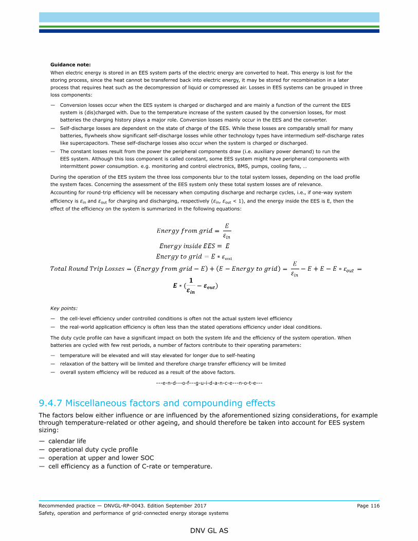
Recommended practice — DNVGL-RP-0043. Edition September 2017 Page 116Safety, operation and performance of grid-connected energy storage systems
DNV GL AS
Guidance note:When electric energy is stored in an EES system parts of the electric energy are converted to heat. This energy is lost for thestoring process, since the heat cannot be transferred back into electric energy, it may be stored for recombination in a laterprocess that requires heat such as the decompression of liquid or compressed air. Losses in EES systems can be grouped in threeloss components:
— Conversion losses occur when the EES system is charged or discharged and are mainly a function of the current the EESsystem is (dis)charged with. Due to the temperature increase of the system caused by the conversion losses, for mostbatteries the charging history plays a major role. Conversion losses mainly occur in the EES and the converter.
— Self-discharge losses are dependent on the state of charge of the EES. While these losses are comparably small for manybatteries, flywheels show significant self-discharge losses while other technology types have intermedium self-discharge rateslike supercapacitors. These self-discharge losses also occur when the system is charged or discharged.
— The constant losses result from the power the peripheral components draw (i.e. auxiliary power demand) to run theEES system. Although this loss component is called constant, some EES system might have peripheral components withintermittent power consumption. e.g. monitoring and control electronics, BMS, pumps, cooling fans, …
During the operation of the EES system the three loss components blur to the total system losses, depending on the load profilethe system faces. Concerning the assessment of the EES system only these total system losses are of relevance.Accounting for round-trip efficiency will be necessary when computing discharge and recharge cycles, i.e., if one-way system
efficiency is εin and εout for charging and discharging, respectively (εin, εout < 1), and the energy inside the EES is E, then theeffect of the efficiency on the system is summarized in the following equations:
Key points:
— the cell-level efficiency under controlled conditions is often not the actual system level efficiency
— the real-world application efficiency is often less than the stated operations efficiency under ideal conditions.
The duty cycle profile can have a significant impact on both the system life and the efficiency of the system operation. Whenbatteries are cycled with few rest periods, a number of factors contribute to their operating parameters:
— temperature will be elevated and will stay elevated for longer due to self-heating
— relaxation of the battery will be limited and therefore charge transfer efficiency will be limited
— overall system efficiency will be reduced as a result of the above factors.
---e-n-d---o-f---g-u-i-d-a-n-c-e---n-o-t-e---
9.4.7 Miscellaneous factors and compounding effectsThe factors below either influence or are influenced by the aforementioned sizing considerations, for examplethrough temperature-related or other ageing, and should therefore be taken into account for EES systemsizing:
— calendar life— operational duty cycle profile— operation at upper and lower SOC— cell efficiency as a function of C-rate or temperature.
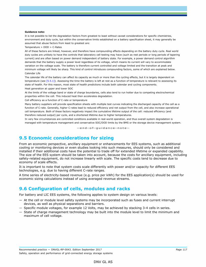
Recommended practice — DNVGL-RP-0043. Edition September 2017 Page 117Safety, operation and performance of grid-connected energy storage systems
DNV GL AS
Guidance note:It is not possible to list the degradation factors from greatest to least without caveat considerations for specific chemistries,environment and duty cycle, but within the conservative limits established on a battery specification sheet, it may generally beassumed that abuse factors from least to greatest are:Temperature > DOD > C-RatesAll of these factors are linked, however, and therefore have compounding effects depending on the battery duty cycle. Real worldduty cycles are unlikely to have the controls that laboratory cell testing may have (such as rest periods or long periods of taperingcurrent) and are often based on power demand independent of battery state. For example, a power demand control algorithmdemands that the battery supply a power level regardless of its voltage, which means its current will vary to accommodatevariation on the voltage scale. The battery is therefore current controlled and voltage limited and the transition at peak andminimum voltage will likely be sharp. This kind of control introduces compounding factors, some of which are explained below.Calendar LifeThe calendar life of the battery can affect its capacity as much or more than the cycling effects, but it is largely dependent ontemperature (see [5.5.1]). Assessing the time the battery is left at rest as a function of temperature is relevant to assessing itsstate of health. For this reason, most state of health predictions include both calendar and cycling components.Heat generation at upper and lower SOCAt the limits of the voltage band or state of charge boundaries, cells also tend to run hotter due to competing electrochemicalproperties within the cell. This induced heat then accelerates degradation.Cell efficiency as a function of C-rate or temperatureMany battery suppliers will provide specification sheets with multiple test curves indicating the discharged capacity of the cell as afunction of C-rate. Generally, higher C-rates lead to reduced efficiency and net output from the cell, and also increase operationalcell temperature. Both of these factors negatively impact the cumulative lifetime output of the cell: reduced efficiency (andtherefore reduced output) per cycle, and a shortened lifetime due to higher temperatures.In very few circumstances are controlled conditions available in real-world operation, and thus overall system degradation ismanaged with temperature management and conservative SOC/DOD limits by the BMS or the storage device management system.
---e-n-d---o-f---g-u-i-d-a-n-c-e---n-o-t-e---
9.5 Economic considerations for sizingFrom an economic perspective, ancillary equipment or enhancements for EES systems, such as additionalcooling or monitoring devices or even studies looking into such measures, should only be considered andinstalled if their additional costs have the potential to trade off for extended lifetime or expanded capability.The size of the EES system should be taken into account, because the costs for ancillary equipment, includingsafety-related equipment, do not increase linearly with scale. The specific costs tend to decrease due toeconomy of scale effects.It is important to note that system costs scale differently with power and/or capacity for different EEStechnologies, e.g. due to having different C-rate ranges.A time series of electricity-based revenue (e.g. price per kWh) for the EES application(s) should be used foreconomic sizing calculations instead of using averaged revenue streams.
9.6 Configuration of cells, modules and racksFor battery and LIC EES systems, the following applies to system design on various levels:
— At the cell or module level safety systems may be incorporated such as fuses and current interruptdevices, as well as physical separations and barriers.
— Specific module voltages, for example 12 Volts, may be achieved by stacking 3-4 cells in series.— State of charge management technology may be built into the module level to limit the minimum and
maximum of cell voltage.

Recommended practice — DNVGL-RP-0043. Edition September 2017 Page 118Safety, operation and performance of grid-connected energy storage systems
DNV GL AS
Guidance note:Battery and supercapacitor systems are constructed using parallel and series configurations of cells in order to achieve voltage andamp-hour (Ah) requirements for the system application (see [2.2]).At the cell or module level safety systems may be incorporated such as fuses and current interrupt devices, as well as physicalseparations and barriers.At any level, the energy of the system is calculated by multiplying the voltage by the amp-hours, i.e.,
Wh = Ah*VPower is calculated by the maximum current multiplied by the voltage, i.e.
W = A * VFor example, a Li-ion cell with a maximum voltage of 4.2 V and a minimum voltage of 2.7 V has a nominal (average) voltage ofaround 3.5 V.Module design: There may be desire to achieve module voltages of 12V, for example, which would be achieved by stacking 3-4cells in series.Conservative SOC management at the cell Level: considerations for SOC management may be built into the module level, wherecell voltage is limited. For example, it has been shown that some cells experience significant capacity loss when cycled to themaximum voltage and therefore at the cell level the maximum voltage may be limited to 4.1 V. Similarly, lower voltages (andcorrespondingly lower SOC) may be limited at the cell level, and rather than cycling to 2.7 V the lower limit may be increased to2.9 or 3.0 V. Limiting the voltage range effectively limits the Ah output of the cell.
---e-n-d---o-f---g-u-i-d-a-n-c-e---n-o-t-e---
9.6.1 Voltage levelsThe output voltage and therefore the series/parallel configuration of a battery rack or capacitor bank shouldbe chosen according to the requirements of the converters, transformers and the allowable voltage level ofthe installation. Between battery rack and converter, high transmission voltage (e.g. 500V – 1000V) or lowtransmission voltage (e.g. 48V DC bus-based modular systems) may be used.
Guidance note:Depending on the converter design and manufacturer, the converter has a certain voltage range on the DC side. On the batteryside, the output voltage is not constant but depends on the SOC. Thus, the minimum and maximum output voltage of the batterysystem should comply with the voltage range of the converter. On top, the converter’s efficiency with respect to the DC voltageshould be considered.In case of a high distance between the batteries and the converter, a high transmission voltage is preferable as this decreaseslosses proportional to the current squared. Also, going towards higher voltages reduces the cable cross section. Besides such highvoltage systems (typical voltage window between 500V and 1000V), modular systems are available (for Li-ion batteries), whichconsist of battery modules usually operating at low voltage (e.g. 48V nominal voltage) and have their own DC/DC-converters whichfeeds into a central DC-bus which is connected to a central AC/DC-converter. Although these modular systems show higher lossesdue to higher currents, they have advantages in terms of lifetime and reliability because in case of malfunction of one batterycell, the respective battery module can be replaced and no compensation currents will occur. In case of the high voltage system,replacing single cells is not efficient because of compensation currents in parallel connections and non-uniform utilization of batterymodules in series connections.
---e-n-d---o-f---g-u-i-d-a-n-c-e---n-o-t-e---
9.6.2 Transportability, weight, volumeFor transport recommendations, see [4.5] and [7.6.1].As battery systems are usually installed within (open) racks or (closed) cabinets, the weight should be statedas gross total weight of the system. Besides that, the resulting load per area should be defined together withattachment points of the battery racks.

Recommended practice — DNVGL-RP-0043. Edition September 2017 Page 119Safety, operation and performance of grid-connected energy storage systems
DNV GL AS
9.7 Accommodation, housing, containment of the system and sub-levelsLi-ion battery and LIC cells should always be assembled within modules. Li-ion battery modules should beself-contained and safety-certified. Li-ion battery modules should be placed in racks or cabinets. The racks orcabinets should be modular so that single modules can be replaced easily.Lead acid batteries are heavy and thus a sturdy support should be used, preferably a rack or a cabinetthat stands directly on the floor. Wall mounted shelves should only be used for small systems, such as asingle computer UPS. For installations in seismically active areas, particular attention should be paid to the(lateral) stability of the support. Lead acid batteries are supplied as blocks containing two, three or six cellsconnected in series, or as single cells. Depending on the technology (AGM, gel, flooded, lead crystal, …),restrictions in mounting position may apply. For example, flooded cells should always be mounted upright.The manufacturer of the battery should provide the mounting requirements in the datasheet of the cell.The battery EES system should be installed within a container as container system or within a special batteryEES system room. Both containments should be specially designed as battery EES system containmentregarding safety issues and also environmental conditions.Existing regulation on this topic may apply for lead acid batteries; reference is made to DIN EN 50272-2. ForLi-ion batteries, standards on this topic are under development.Converters are enclosed and may be installed in containers or in a building. In both cases, climate conditionsystems should be provided to guarantee the required operation temperature range.Further electronic components like SCADA and BMS should also be installed in climate regulated rooms orcontainers.See [4.5] for transportation and warehousing and to Sec.8 for environmental considerations.Relocation of a mobile EES storage system such as a container-based system should be considereda new project for which all life cycle phases and their corresponding activities should be checked andupdated if necessary (see Sec.4). Even when it is expected that much existing information applying to theprevious location (e.g. required documents or safety analyses) may be reusable with little or no adaptation,performing a complete check is essential because small changes in the situation may have a big impact.

Recommended practice — DNVGL-RP-0043. Edition September 2017 Page 120Safety, operation and performance of grid-connected energy storage systems
DNV GL AS
SECTION 10 ECONOMICS
10.1 Life cycle costsLife cycle costs (LCC) should be included in economic analyses. The idea of LCC compared to an approachsolely based on investment cost (or capital expenditures, CAPEX) is that all the costs that arise during thelifetime (e.g. operational expenditures, OPEX) are included in the analysis. The lifetime phases includeacquisition, operation, and disposal at the EoL. When determining the LCC, storage technology-relatedparameters and storage application-related parameters should be taken into account. The advantage of thisapproach is that trade-offs can be identified between CAPEX and costs for the operation of the system or itsdisposal.For the conduction of a LCC analysis reference is made to IEC 60300-3-3:2004.The following parameters should be considered when calculating LCC of an EES system:
— system characteristics:
— charge efficiency (ηcharging)— discharge efficiency (ηdischarging)— maximum DOD (DODmax)— maximum cycle number, under conditions as defined in the performance standard applicable to the EES
technology (see also [5.5.2]). If the performance standard does not provide these conditions, an EOLcondition and a method of testing shall be included in the system specification
— self-discharge losses— calendar lifetime.
— spplication-related parameters:
— required system lifetime, which may be significantly shorter than the ESS system lifetime— energy demand (power times supply period), which should not be confused with the installed storage
capacity— charging power— discharging power— cycles per day— cycle depth— financial conditions— electricity price during charging, including costs per kWh, capacity fees and distribution and
transmission costs.
— capital costs:
— capacity-related costs (per kWh). For redox flow batteries, costs for the electrolyte and its tanks arecategorized as capacity-related costs
— power -related costs include the components that scale with increased power. For redox flow batteries,the costs for stacks and pumps are power related costs
— peripheral costs per installed kilowatt-hours, including at least the following if present: managementsystems e.g. for cell monitoring, cell balancing – and HVAC systems
— power converter or motor/generator costs, taking into account losses and lifetime.— other power related costs, e.g. housing of stacks.
— construction and commissioning costs
— maintenance, repair and operational costs, both fixed and variable
— decommissioning or replacement costs and residual value
— grid-connection costs
— availability of the system and resulting costs of downtime
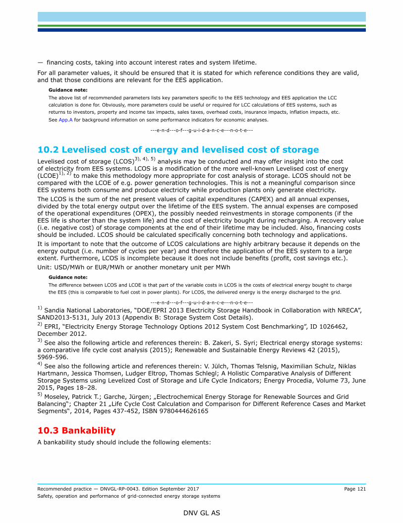
Recommended practice — DNVGL-RP-0043. Edition September 2017 Page 121Safety, operation and performance of grid-connected energy storage systems
DNV GL AS
— financing costs, taking into account interest rates and system lifetime.
For all parameter values, it should be ensured that it is stated for which reference conditions they are valid,and that those conditions are relevant for the EES application.
Guidance note:The above list of recommended parameters lists key parameters specific to the EES technology and EES application the LCCcalculation is done for. Obviously, more parameters could be useful or required for LCC calculations of EES systems, such asreturns to investors, property and income tax impacts, sales taxes, overhead costs, insurance impacts, inflation impacts, etc.See App.A for background information on some performance indicators for economic analyses.
---e-n-d---o-f---g-u-i-d-a-n-c-e---n-o-t-e---
10.2 Levelised cost of energy and levelised cost of storageLevelised cost of storage (LCOS)3), 4), 5) analysis may be conducted and may offer insight into the costof electricity from EES systems. LCOS is a modification of the more well-known Levelised cost of energy(LCOE)1), 2) to make this methodology more appropriate for cost analysis of storage. LCOS should not becompared with the LCOE of e.g. power generation technologies. This is not a meaningful comparison sinceEES systems both consume and produce electricity while production plants only generate electricity.The LCOS is the sum of the net present values of capital expenditures (CAPEX) and all annual expenses,divided by the total energy output over the lifetime of the EES system. The annual expenses are composedof the operational expenditures (OPEX), the possibly needed reinvestments in storage components (if theEES life is shorter than the system life) and the cost of electricity bought during recharging. A recovery value(i.e. negative cost) of storage components at the end of their lifetime may be included. Also, financing costsshould be included. LCOS should be calculated specifically concerning both technology and applications.It is important to note that the outcome of LCOS calculations are highly arbitrary because it depends on theenergy output (i.e. number of cycles per year) and therefore the application of the EES system to a largeextent. Furthermore, LCOS is incomplete because it does not include benefits (profit, cost savings etc.).Unit: USD/MWh or EUR/MWh or another monetary unit per MWh
Guidance note:The difference between LCOS and LCOE is that part of the variable costs in LCOS is the costs of electrical energy bought to chargethe EES (this is comparable to fuel cost in power plants). For LCOS, the delivered energy is the energy discharged to the grid.
---e-n-d---o-f---g-u-i-d-a-n-c-e---n-o-t-e---1) Sandia National Laboratories, “DOE/EPRI 2013 Electricity Storage Handbook in Collaboration with NRECA”,SAND2013-5131, July 2013 (Appendix B: Storage System Cost Details).2) EPRI, “Electricity Energy Storage Technology Options 2012 System Cost Benchmarking”, ID 1026462,December 2012.3) See also the following article and references therein: B. Zakeri, S. Syri; Electrical energy storage systems:a comparative life cycle cost analysis (2015); Renewable and Sustainable Energy Reviews 42 (2015),5969-596.4) See also the following article and references therein: V. Jülch, Thomas Telsnig, Maximilian Schulz, NiklasHartmann, Jessica Thomsen, Ludger Eltrop, Thomas Schlegl; A Holistic Comparative Analysis of DifferentStorage Systems using Levelized Cost of Storage and Life Cycle Indicators; Energy Procedia, Volume 73, June2015, Pages 18–28.5) Moseley, Patrick T.; Garche, Jürgen; „Electrochemical Energy Storage for Renewable Sources and GridBalancing“; Chapter 21 „Life Cycle Cost Calculation and Comparison for Different Reference Cases and MarketSegments“, 2014, Pages 437-452, ISBN 9780444626165
10.3 BankabilityA bankability study should include the following elements:

Recommended practice — DNVGL-RP-0043. Edition September 2017 Page 122Safety, operation and performance of grid-connected energy storage systems
DNV GL AS
— Company review: company history (including company management staff), product line sales history, highlevel financials, intellectual property (including patent protection and knowledge management), referenceprojects.
— Technology review: design for reliability and longevity, product specifications (energy storage capacity,maximum power, cycle lifetime, calendar lifetime, end-of-life and residual value), architecture andtopology (for battery systems: including cell, sub-module, module with sub-battery managementsystem and system with system-level battery management system), product efficiency (round-trip ACand DC efficiency), use cases (application and operational use of the product against this application,decommissioning (second life or recycling).
— Quality review: manufacturing evaluation, quality management systems (QMS), in-house and 3rd partytesting and certification activities and processes, operation and maintenance provisions (includingmonitoring processes), regulatory compliance.
— Reliability review: field history and root cause analysis, warranty and available guarantees, productsupport infrastructure, operating site visit.
— Safety review: safety design, environmental impact, FMEA.Guidance note:A bankability study is an independent technology evaluation concluding in a bankability report including: a company review, atechnology review, a quality review, a reliability review and a safety review. The principal objective of a bankability study, is toassess the risks associated with a product.A bankability study may involve a risk assessment of product claims, based on technical and commercial specifications, and anassessment of performance and reliability against these claims. For each of the individual claims, a separate technical assessmentshould be conducted, including the product claim itself, a description of the claim and whether the claim is met, needs to beproven, or is not likely to be met.A bankability study is typically required by developers and lenders, and typically contracted by the product or systemmanufacturers themselves. The result of a bankability study is a bankability report, describing the outcomes of the assessment.
---e-n-d---o-f---g-u-i-d-a-n-c-e---n-o-t-e---
10.4 Residual valueThe residual value of the EES system is depending on the remaining lifetime of the specific application andthe price of a new EES system. The following parameters should be considered when calculating the residualvalue of an EES system:
— remaining capacity— remaining calendar life— remaining energy throughput for specific application— refurbishment cost— transportation cost— installation cost— recycling cost (e.g. of any hazardous materials and electronic systems)— warranties— historical data of the EES system.
Guidance note:Appraising used EES systems is difficult since the use of the EES system in the first application can strongly influence theremaining lifetime. Historical cycling data can help to appraise the used EES system. If historical cycling data is not availablea simple capacity test is needed for a rough estimation of the residual value. For a sophisticated estimation of the residualvalue a test program is needed. For lithium containing batteries a test program is needed that test the cells at different C-rates,temperatures, DOD and SOC
---e-n-d---o-f---g-u-i-d-a-n-c-e---n-o-t-e---

Recommended practice — DNVGL-RP-0043. Edition September 2017 Page 123Safety, operation and performance of grid-connected energy storage systems
DNV GL AS
10.4.1 Residual life and value of the power converterThe following aspects will have a positive influence on the residual life/value of a converter:
— the converter is still within the manufacturer’s warranty period and this warranty is transferrable to thenew owner
— the converter is still an active product of the manufacturer, or a sufficiently strong statement is availablefrom the manufacturer about continued future product support
— the converter’s components are still available, or suitable drop-in replacements are available andauthorized as service parts by the converter manufacturer
— the converter’s service history shows no events that point to abuse or sustained overloads, or repairs thattypically follow from such events
— the converter can be inspected while still in the original system, or it is competently decommissioned andproperly stored afterwards
— the converter has always operated in a clean environment.Guidance note:Power electronic devices do not show a measurable performance degradation like batteries do when they age. Instead, theyeither work or they don’t, and a noticeable performance degradation is usually a precursor to failure. Manufacturers of powerelectronics typically specify a warranty period in years and/or power-on hours, and an expected lifetime in power-on hours undergiven circumstances. The expected life is dependent on component temperature and site conditions like dust, moisture andvibration. Therefore, it is often difficult to determine how long a given piece of equipment will function reliably without doing adetailed assessment of the state of the power converter’s critical components. A power-on-hours meter is useful for schedulingmaintenance for a power converter, but it is only of limited use in determining its residual life expectancy. For example, an inverterwith 40k half-power hours in cool climatic conditions on the meter, will probably have a longer residual life than the same inverterthat has done 20k full-power hours in its maximum ambient temperature. In a functional test however, both inverters will performidentically. Cleanliness of the environment is also a factor: an insulating layer of dust/dirt on components can cause a significantrise of a component’s operating temperature, consequently shortening its lifespan.The more of the above points are met by a converter, the higher its residual value will be. A converter which satisfies noneof these points is not necessarily a bad converter, but its residual value will be diminished by the inability to ensure its futurereliability. Converter manufacturers can sometimes provide inspection/refurbishment services for used converters, which mayinclude an assessment of the condition of critical components, replacement of aged components, sometimes a hardware update ormodification, and a system software update. After this, the converter is again covered by a warranty period.
---e-n-d---o-f---g-u-i-d-a-n-c-e---n-o-t-e---

Recommended practice — DNVGL-RP-0043. Edition September 2017 Page 124Safety, operation and performance of grid-connected energy storage systems
DNV GL AS
APPENDIX A LIFE CYCLE COST BACKGROUND INFORMATIONLCC depends on two different characterizing parameters, the storage technology and the storage application.Technology parameters focus on the EES technology itself such as self-discharge and calendar lifetime.Application parameters characterize the way of operation of the system in a specific application and includeparameters such as capital costs and cycles per day.It is possible to calculate LCC in different ways and with varying depths of analysis. The LCC definitionused here puts the main emphasis on the static and simplified calculation with respect to correct sizing ofcomponents and their efficiency.More information on key parameters for LCC calculations is given below.
Charge efficiency (ηcharging)This factor includes the efficiency of the EES system and of power electronics during charging. For calculatingthe charging losses at stationary ESS, it is also necessary to take the consumed energy during charging intoaccount. Therefore, efficiency (hsystem), power (Pcharge_in) and energy (Ein) are important for the analyses ofLCC.
Discharge efficiency (ηdischarging)As well as at the charge process, during the discharge process the efficiency for the EES system and thepower electronics should be added. Furthermore, there is another important factor, considering in thiscase: the depth of discharge (DODmax). This value represents the available physical capacity, on which thecalculation for ESS costs typically based. In Equation A.1 to Equation (A.3) the circumstances of the two(dis/-charge) efficiencies are shown.
(A.1)
(A.2)
(A.3)
Maximum DODmax
This parameter defines the real available capacity of the EES system. It depends on the working concepts orrespectively on the cycle characteristic.Maximum cycle numberNumber of cycles with 100% DOD which the EES system can operate until the EoL is reached. How fast thiscritical limit is achieved during cycling operation, correlates direct to the DODmax. For many battery EESsystems, shallower cycles cause much less damage than deep cycles do.Calendar lifetimeThis means the period in which the EES system remains constantly in a defined state without any dischargeand charge cycles. Not only the storage medium itself could be a limiting component, other components ofthe EES system (such as the converter’s calendar lifetime) shall also be considered.Cost per installed kWhThis parameter includes the marginal costs per installed capacity in kWh. For battery EES systems, this isdependent on the purchased battery cells. For redox flow batteries, a further differentiation should be made.

Recommended practice — DNVGL-RP-0043. Edition September 2017 Page 125Safety, operation and performance of grid-connected energy storage systems
DNV GL AS
The costs for stacks and pumps are specified as power-related costs and electrolyte and its tanks costs arecategorized in the installed kilowatt-hour. For compressed and liquid air energy storage systems the costs perinstalled kWh would depend only on the costs of thermal and air stores.Power converter costsIn order to connect the ESS to the grid, a power converter is necessary. The power conversion is subject tolosses, which should be taken into account during the dimensioning of the ESS. Furthermore, the lifetimeshould be considered.Other power related costsUnder this point costs for e. g. grid connection and housing of stacks shall be considered.Engineering, Procurement, Construction costsAll financial resources, which are spent on the ESS building and finalisation, are mainly proportional to theinstalled capacity and power.Maintenance, repair and operational costsThis point includes only the technology typical operation costs. This means spare parts, operation andmaintenance the operator needs to take into account. The costs are mostly calculated as percentages ofthe investment per year. Further specification of repair and maintenance costs can be in terms of fixed andvariable maintenance costs and the costs of major maintenance (once every n years) and replacement costs/kWh (once every n years) like battery cell replacement to maintain energy capacity.Application parametersFor the evaluation of the EES economy it is necessary to consider defined operating variables. Someparameters depend on the commercialization strategy like charging power, discharging power, cycles per dayand energy demand. Independently from the operating scenario are the electricity price, the required systemlifetime and the capital costs.Electricity priceTo calculate the LCC, only the electricity price during charging is relevant. Further losses, which occurs duringdischarging or storage periods shall be taken into consideration through adjusting the installed capacity.Electricity prices could include system charges.Financing costsLarge EES systems are a very capital-intensive investment. Therefore, capital costs have a huge influence onthe LCC. Furthermore, the interest rates, depending on the initial investment, and the lifetime of the systemare major influencing factors at LCC. This means an EES system with a short lifetime have high interest ratesand a system with a long lifetime have low interest rates.Required system lifetimeThe required system lifetime does not correlate with the lifetime of the EES system. The first one can besignificantly shorter. Due to changing of market demands or on-going development the functionality ofthe storage system could be replaced. Reliable market predictions are only possible within a short timespan. Therefore, the refinancing of the EES system should be completed during this time span. Residualtechnical lifetime of hydro storage and air storage can be orders of magnitude longer than other componentsin the EES system and are therefore harder to value or are only devaluing as a result of market price andavailability.Energy demandThe energy demand results from multiplication between the maximum discharge Power Pdischarge_out and thetime period, while power is supplied to the grid. The value should not be confounded with the installed sizeof the EES system Estorage. Estorage depends on parameters such as efficiencies and maximum DOD. For sizinga storage system these parameters and different storage technologies should be taken into consideration.After all the installed storage energy shall supply the energy demand if required and in the whole range it isneeded, independent from the chosen technology and the design.Cycles per dayTo find out the profitable business case, the user should know how many cycles per day will be demandedand the respective cycle depth. These two factors define the energy, which can be transformed and suppliedat the market.

Recommended practice — DNVGL-RP-0043. Edition September 2017 Page 126Safety, operation and performance of grid-connected energy storage systems
DNV GL AS
APPENDIX B REGULATIONS, STANDARDS AND LEGAL ISSUES
B.1 GeneralThe standards, model codes, rules, regulations (documents) and legal issues addressed in this Appendixshould be reviewed as they could be relevant to EES design, installation, commissioning, operations,maintenance, alterations and re-use or decommissioning. As such they are also relevant to the myriad ofEES system stakeholders because they provide guidance (or requirements) related to various stakeholderroles. Even more important to be aware of these documents are changing rapidly, with many on continuousmaintenance and others revised on specific cycles that have established deadlines for consideration ofrevisions. Relevant existing and upcoming regulations are listed, as well as some examples and possiblefuture updates are provided to assist users of this document identify standards, model codes, rules,regulations and legal issues as a function of EES type, location and which entities are involved in theiradoption and enforcement.Disclaimer: this Appendix is not intended to provide a full overview of applicable documents to any situation,and it does not relieve the user from the obligation to perform a thorough study of the documents that areapplicable to actual situations associated with the EES technology or its application in the built environment(e.g. application(s), geographical location, environmental conditions).
B.2 Structure of existing legal frameworks, regulations and codes
B.2.1 Europe – European UnionB.2.1.1 Regulations and Directives of the European Parliament and of the CouncilElectricity Directive 2009/72/EC 1) – (part of the EU third energy package) concerning the common rules forthe internal market in electricity; e.g. about the principle of unbundling.1)http://eur-lex.europa.eu/LexUriServ/LexUriServ.do?uri=OJ:L:2009:211:0055:0093:EN:PDFRenewable Energy Directive 2009/28/EC – (Recital 57): 'There is a need to support the integration of energyfrom renewable sources into the transmission and distribution grid and the use of energy storage systems forintegrated intermittent production of energy from renewable sources'.Energy Efficiency Directive (2012) – which states that ‘Network regulation and tariffs shall not preventnetwork operators or energy retailers making available system services for […] the storage of energy’Directive 2006/66 (Battery Directive) on batteries and accumulators and waste batteries and accumulatorsRegulation (EU) No 347/2013 – on guidelines for trans-European energy infrastructure.ACER = Agency for the Cooperation of Energy Regulators (a European Community body)ACER was mandated according to Regulation (EC) No 713/20091) to propose Framework Guidelines, basedon which, ENTSO-E develops legally binding network codes (Regulation (EC) No 714/20092)) for cross-bordernetwork and market integration issues, without prejudice to the Member States’ right to establish nationalnetwork codes which do not affect cross-border trade.All EU Member States and other European countries have their own Energy laws and Network Codes. Theseare in a constant process of European harmonization.Winter PackageOn 30 November 2016, the Commission released its new ‘Clean Energy For All Europeans’ Package (a.k.a.Winter Package), in line with its commitment to make of 2016 “the year of delivery” on the Energy Unionframework strategy further developing the internal energy market. The new package includes 11 legislativeproposals (recasts of existing legislation and some new laws), 6 non-legislative Commission Communicationsand dozens of accompanying documents (impact assessments, reports, annexes, guidelines and fitnesschecks), around three overarching goals: (1) putting energy efficiency first (2) achieving global leadershipin renewable energies; and (3) providing a fair deal for consumers. The proposals address energy efficiency,

Recommended practice — DNVGL-RP-0043. Edition September 2017 Page 127Safety, operation and performance of grid-connected energy storage systems
DNV GL AS
renewable energy, the re-design of the electricity market, security of electricity supply and governance of theEnergy Union. According to expectations, the legislation could enter into force end 2019 / beginning 2020.Whereas storage was not explicitly mentioned in the third energy package (proposed by EC in 2007, adoptedby EP in 2009, entered into force 3 September 2009), it receives quite some attention in the winter package.Among others, the following main issues are identified:
— Definition: an energy storage has been included in Art. 2 (48), saying that: ‘energy storage’ means, in theelectricity system, deferring an amount of the electricity that was generated to the moment of use, eitheras final energy or converted into another energy carrier.
— Level playing field: Art. 1 of the proposal for a revised Electricity Directive, highlights energy storage asa key element of the energy system mentioning storage in relation to the common rules. Accordingly,national legislation should not hamper energy storage (Art. 3 (1) of the proposal for a revised ElectricityDirective); energy storage is identified as an element of TSO network planning (Art. 45 (3) of the proposalfor a revised Electricity Directive); energy storage is identified as an alternative to grid expansion andpart of DSO network planning (Art. 32 (2) of the proposal for a revised Electricity Directive); and energystorage should be taken into account in resource adequacy assessments (Art. 19 (4) of the proposal for arevised Electricity Regulation).
— Ownership: the tasks and roles of DSOs and TSOs are clarified in Chapter IV (Art. 29 to 38) andChapters V and VI (Art. 40 to 56) of the proposal for a revised Electricity Directive. It says that DSOs andTSOs shall not be allowed to own, develop, manage or operate storage facilities, except under specificconditions.
— Market access: organise electricity markets in a more flexible manner and to fully integrate all marketplayers (including energy storage) – also for the non-frequency ancillary services, also facilitate cross-border access for new suppliers of electricity like storage, and DSOs are enables to procure services fromresources such as storage.
— Application of Network codes: Chapter VII (Art. 54-59) of the proposal for a revised Electricity Directiveexpands the possible content of network codes and guidelines adopted in the form of delegated acts bythe Commission, to areas such as distributions tariff structures, ancillary services, demand response,energy storage, cyber security, ROCs functioning, curtailment and redispatch of generation.
1)http://eur-lex.europa.eu/LexUriServ/LexUriServ.do?uri=OJ:L:2009:211:0001:0014:EN:PDF2)http://eur-lex.europa.eu/LexUriServ/LexUriServ.do?uri=OJ:L:2009:211:0015:0035:EN:PDF
B.2.1.2 Grid codesThe European Network Codes (or Grid Codes) are under development and in the EU legalization process. The10 Grid Codes of ENTSO-E (European Network of Transmission System Operators for Electricity):Grid connection related codes:
— requirements for generators— demand connection code— HVDC connection code.
System operation related codes:
— operational security network— operational planning and scheduling— load frequency control and reserves— emergency and restoration.
Market related codes:
— capacity allocation and congestion management— forward capacity allocation— balancing network code.
All EU Member States and other European countries have their own Energy laws and Network Codes. Theseare in a constant process of European harmonization.

Recommended practice — DNVGL-RP-0043. Edition September 2017 Page 128Safety, operation and performance of grid-connected energy storage systems
DNV GL AS
See [6.2] and the grid code overview provided online by DNV GL6.In general, there is no mention of energy storage in European electrical energy legislation or regulations.Exceptions are Germany, UK and Italy, as will be further explained below.7
— In Germany, the grid codes make no special requirements on storage, however it shall meet both therequirements on load and on generation, depending on its operation mode. In this context, referenceis made to the technical guidelines of BDEW8 and VDE9 on integration of DER and EES. About marketintegration, the EEG covers storage of RES and the Transmission Code explicitly mentions storage as anoption for the reserve/balancing power markets without mentioning other applications of EES.
— In the Netherlands, FCR distinguishes between limited and conventional sources of primary reserve.Limited resources are a reference to energy stores. In case of full call off, EES systems working for FCRare allowed a 2-hour period to restore energy balance since EES systems are energy neutral applications.
About incentive schemes, the EnWG exempts new build storage and refurbished PHS from network usagefees; and the EEG ensures that storage of RES will preserve the same remuneration payable for RES directlyfed into the grid (at the same time prohibiting energy stored from the grid to be sold back with the RES feed-in tariff). While actually neutral, the tone of the EnWG indicates a focus on large scale, centralised storage(according to EASE).In Italy, at the moment the energy storage systems connected to the grid must respect the regulation forthe connection of a generator to the transmission/distribution grid. Decree law 93/11: TSO (and DSOs)can build and operate batteries. However, the TSO shall justify, through a cost/benefit analysis, that theenergy storage system is the most efficient way to solve the problem identified (e.g. compared to buildinga new line…). In any case the TSO should not receive a remuneration higher than the (measurable) cost ofalternative solutions.In the UK, storage is explicitly mentioned in capacity market regulations. Also, a recent service namedEnhanced Frequency Response is explicitly aimed at EES systems.
B.2.2 United StatesThe development of legislation, rules, regulations, codes, and standards (criteria) and related documents inthe United States and then their adoption and implementation can be challenging to understand. There aretwo key aspects to consider in the U.S., who develops the criteria and then who adopts them and how theyare adopted. The development of the criteria can be directly by the entity with authority to adopt the criteriaor it can be through adoption of criteria developed by private sector standards development organizations(SDOs), which involve all stakeholders including potential adopters. Adoption can be through a number ofgovernmental vehicles at the federal, state, local, territorial or tribal level as well as through private sectorvehicles such as insurance policies, contracts, or incentive programs. In addition, a third component of thisprocess involves conformity assessment, which involves documenting with the criteria that are adopted andthen validating the criteria are satisfied (e.g. enforcement). While the adopting entity has the authority tovalidate compliance and will undertake the necessary enforcement activities to ensure compliance they willalso rely on documentation provided by third parties (e.g. testing or certification of products or plans andspecifications prepared by a registered design professional).The federal government, through legislative or executive branches of government, ultimately can have pre-emptive authority over state or local government or private sector interests. As such, the federal governmentcan be a developer of specific criteria or, as discussed below, can also participate in and/or adopt criteriadeveloped in the private sector (e.g. model codes, standards, guidelines). One specific exception to thisinvolves the 500+ U.S. Indian Tribes in the U.S., who have sole authority to govern the property that eachtribe owns. Beyond the federal government state, local and territorial government can develop, adopt and/
6 www.dnvgl.com/GridCodeListing.pdf7 European Association for Storage of Energy, Survey on National Regulations related to Energy Storage,
February 2012.8 BDEW, Generating Plants Connected to the Medium-Voltage Network, https://www.bdew.de/internet.nsf/
id/A2A0475F2FAE8F44C12578300047C92F/$file/BDEW_RL_EA-am-MS-Netz_engl.pdf9 VDE, Anschluss und Betrieb von Speichern am Niederspannungsnetz, www.vde.com/de/fnn/
arbeitsgebiete/documents/fnn_th_speicher_2013-06.pdf

Recommended practice — DNVGL-RP-0043. Edition September 2017 Page 129Safety, operation and performance of grid-connected energy storage systems
DNV GL AS
or enforce laws, rules and regulations as can utilities and private sector interests such as insurance carriers,lenders and investors/property developers.One way to segment the U.S. situation to facilitate a better understanding of the myriad of possible laws,rules, regulations, policies, programs, codes and standards is to cover first those initiatives that are notgenerally tied to specific model codes and standards as discussed in section [B.3]. And then cover thoseinitiatives that are tied to specific model codes and standards which can be generally classified as buildingconstruction regulations.
B.2.2.1 Federal rules, regulations, policies, programs and lawsThe Federal Energy Regulatory Commission (FERC) has the authority to develop, adopt and apply rulesand regulations to the electric utility industry. A listing of FERC orders is provided below, noting that thesewill focus on the way utilities operate and would not generally delve into for instance the safety rules andregulations a utility would have to adopt and apply to an EES.FERC Order 719 – Wholesale Competition in Regions with Organized Electric Markets (Issued October17, 2008). This order amends FERC regulations under the Federal Power Act to improve the operation oforganized wholesale electric markets in the areas of: (1) demand response and market pricing during periodsof operating reserve shortage; (2) long-term power contracting; (3) market-monitoring policies; and (4)the responsiveness of regional transmission organizations (RTOs) and independent system operators (ISOs)to their customers and other stakeholders, and ultimately to the consumers who benefit from and pay forelectricity services. Each RTO and ISO will be required to make certain filings that propose amendments toits tariff to comply with the requirements in each area, or that demonstrate that its existing tariff and marketdesign already satisfy the requirements.FERC Order 755 – Frequency Regulation Compensation in the Organized Wholesale Power Markets (IssuedOctober 20, 2011). FERC Order 755 institutes "pay for performance" compensation in the wholesaleregulation market. This order states that both speed and accuracy of following grid operators’ instructions toprovide frequency regulation should be taken into consideration in designing tariffs for the provision of thisservice.FERC Order 784 – Third-Party Provision of Ancillary Services; Accounting and Financial Reporting for NewElectric Storage Technologies (Issued July 18, 2013). This order requires transmission providers to considerspeed and accuracy of regulation resources in its determination of regulation and frequency responserequirements.FERC Order 792 – Small Generator Interconnection Agreements and Procedures (Issued November 22,2013). This order revises small generator interconnection agreements and procedures. Among manyrevisions, the ruling specifies that energy storage systems shall be included in the agreement and proceduresas a power source. This effectively puts energy storage in the same category as existing small generators.The U.S. Congress also has legislative authority to enact laws that can impact EES. Some examples areprovided below, noting once enacted legislation can subsequently be modified or eliminated by futureCongressional action or the legislation can direct an executive branch agency to develop rules, regulations orprograms to implement the basic direction provided in the legislation.MLP Parity Act S. 795 (by U.S. Senate) – This is a bill to amend the Internal Revenue Code of 1986 to extendthe publicly traded partnership ownership structure to energy power generation projects and transportfuels, and for other purposes. A Master Limited Partnership (MLP) is a business structure that is taxed as apartnership, but whose ownership interests are traded like corporate stock on a market. This allows for lowerlevels of taxation, as taxes are imposed at the shareholder level but not at the larger corporate structure.Historically, MLPs have only encompassed fossil fuel-based energy partnerships within the internal revenuecode. The MLP Parity Act expands MLP eligibility to an array of renewable energy sources, including electricitystorage devices.Storage Act of 2011 S.1845 (by U.S. Congress) – This bill amends the Internal Revenue Code of 1986 toprovide for an energy investment credit for energy storage property connected to the grid, and for otherpurposes.Energy Storage Safety Strategic Plan (by Department of Energy (DOE)) – The Office of Electricity Deliveryand Energy Reliability (OE) has worked with industry and other stakeholders to develop the Energy StorageSafety Strategic Plan, a roadmap for grid energy storage safety that highlights safety validation techniques,incident preparedness, safety codes, standards, and regulations and the implementation of activities to

Recommended practice — DNVGL-RP-0043. Edition September 2017 Page 130Safety, operation and performance of grid-connected energy storage systems
DNV GL AS
support the roadmap objective to facilitate the timely deployment of save EES. In May of 2017 an ESS SafetyRoadmap (PNNL-SA-126115 | SAND2017-5140 R) was released by PNNL and Sandia National Laboratories tofurther the strategic plan. The goal of that document is to “Foster confidence in the safety and reliability ofenergy storage systems”.Energy Storage Technology Advancement Partnership (by Department of Energy (DOE)) – The EnergyStorage Technology Advancement Partnership (ESTAP) is a new, cooperative funding and information-sharingpartnership between the U.S. Department of Energy (DOE) and interested states that aims to accelerate thecommercialization and deployment of energy storage technologies in the United States via joint funding andcoordination.Smart Grid Investment Grant Program (by Department of Energy (DOE)) – The Smart Grid InvestmentGrant (SGIG) program is authorized by the Energy Independence and Security Act of 2007, Section 1306, asamended by the Recovery Act. The purpose of the grant program is to accelerate the modernization of thenation’s electric transmission and distribution systems and promote investments in smart grid technologies,tools, and techniques that increase flexibility, functionality, interoperability, cybersecurity, situationalawareness, and operational efficiency. Per the SGIG 2012 report, at least one funded project explicitlyidentifies storage as being a factor of the smart grid itself. More may include energy storage but do not list itexplicitly.Smart Grid Demonstration Program (by Department of Energy (DOE)) – The Smart Grid DemonstrationProgram (SGDP) is authorized by the Energy Independence and Security Act of 2007, Section 1304, asamended by the Recovery Act, to demonstrate how a suite of existing and emerging smart grid concepts canbe innovatively applied and integrated to prove technical, operational, and business-model feasibility. Theaim is to demonstrate new and more cost-effective smart grid technologies, tools, techniques, and systemconfigurations that significantly improve on the ones commonly used today.
B.2.2.2 State, local, territorial and tribal rules, regulations, policies, programs and lawsSimilar to the Federal government, state, local and territorial legislatures, state public utility commissionsand U.S. Indian tribal councils, can have the authority to develop and adopt laws, rules, regulations andother requirements that impact the built environment. How they exercise any authority varies widely fromstate to state and within the states as well as from local to local, territory to territory and Indian tribeto Indian tribe. As mentioned above for federal initiatives there will also be variations in the authority ofstate, local and territorial legislative or executive branch entities. Where one entity has control or authorityover another that entity is considered to pre-empt the other entity or entities over which is has ‘control’.Indian tribes, on the other hand, operate as separate autonomous entities with no one controlling theirauthority other than those empowered to govern and manage tribal affairs. As discussed under rules andregulations below, states and territories that have authority over local government entities (e.g. cities,counties, townships, fire districts, etc.) will adopt rules and regulations that can pre-empt (preclude) actionby those entities within the state or territory. Such pre-emption can be complete, may vary based on topicscovered by the rules and regulations, or may allow those pre-empted to adopt more stringent rules andregulations above those set by the state or territory.There are numerous state and local legislative activities related to energy storage technologies. Some ofthose are summarized below, in addition to some studies being undertaken by selected states. It should benoted that the incidence of proposed legislative activity at the state and local level impacting energy storagetechnology is expected to increase over time, however, most of those initiatives will be focused on improvingthe value proposition for energy storage as opposed to safety, which as discussed below is addressed not bylegislative action but generally through regulatory action through adoption of codes and standards.California Assembly Bill 1150 AB 1150 (by California Legislature) – This bill extends the funding of theCalifornia Public Utility Commission's (CPUC's) Self-Generation Incentive Program (SGIP) by three years(through December 2014) at $83 million per year, and requires the commission to evaluate the program toachieve specified goals. In addition, the bill specifically states that energy storage is eligible in this program,whether standalone, or when coupled with PV. Existing law requires the CPUC to administer the program untilJanuary 1, 2016.California Assembly Bill 2514 AB 2514 (by California Legislature) – This law requires the California PublicUtilities Commission (CPUC) to open a proceeding to determine appropriate utility procurement targets, ifany, for energy storage systems that are commercially available and cost-effective. At its October 17, 2013

Recommended practice — DNVGL-RP-0043. Edition September 2017 Page 131Safety, operation and performance of grid-connected energy storage systems
DNV GL AS
meeting, the Commission adopted a 1.325 GW procurement target for energy storage by 2020, with biannualtargets increasing every two years from 2016-2020. The targets were further broken up by "use casebuckets" (transmission-connected, distribution-connected, and behind-the-meter) and by each of California'sthree Investor Owned Utilities (IOUs). Electric Service Providers and Community Choice Aggregators weredirected to procure energy storage resources equivalent to 1% of their peak capacity by 2020.Self-Generation Incentive Program R. 12-11-005 (by California Public Utilities Commission) – The CPUC'sSelf-Generation Incentive Program (SGIP) provides incentives to support existing, new, and emergingdistributed energy resources. The SGIP provides rebates for qualifying distributed energy systems installedon the customer's side of the utility meter. Qualifying technologies include wind turbines, waste heat topower technologies, pressure reduction turbines, internal combustion engines, microturbines, gas turbines,fuel cells, and advanced energy storage systems.Long-Term Procurement Planning: Rulemaking 12-03-014 (by California Public Utilities Commission) – ThisCPUC rule-making is part of the state's long-term procurement planning (LTPP), which authorizes the state'sinvestor owned utilities (IOUs) to procure certain amounts of electricity capacity and directs those utilities topurchase at least a certain amount of various listed capacity resources. This was a landmark ruling becauseit was the first state decision directing an IOU to procure a certain amount of energy storage capacity. It alsostates that “energy storage resources should be considered along with preferred resources,” and that the twocategories may be procured up to 800 MW total capacity.Storage OIR Proceeding R. 10-12-007 (by California Public Utilities Commission) – In December 2010, theCPUC opened Rulemaking R.10-12-007 to set policy for California utilities and load-serving entities (LSEs) toconsider the procurement of viable and cost-effective energy storage systems. In addition, the CPUC shouldconsider a variety of possible policies to encourage the cost-effective deployment of energy storage systems,including refinement of existing procurement methods to properly value energy storage systems.Electric Program Investment Charge (by California Public Utilities Commission) – The California Public UtilitiesCommission established the purposes and governance for the Electric Program Investment Charge in Decision12-05-037 for Rulemaking 11-10-003 on May 24, 2012. In this decision, the CPUC designated the EnergyCommission as one of four administrators of the program and required administrators to submit coordinatedinvestment plans to the CPUC for consideration no later than November 1, 2012.Con Edison Load Reduction Incentives (by Con Edison/ NYSERDA) – As part of the contingency plan forthe potential closure of the Indian Point nuclear reactor, Con Edison filed a proposal to provide 100MW ofload reduction measures including demand response, energy efficiency and energy storage. ConEdison andNYSERDA made some of the details public for the program.Texas Senate Bill 943 (by Texas Legislature) – SB 943 relates to the classification, use, and regulation ofelectric energy storage equipment or facilities when transacting in the wholesale market. The bill providesthat when energy storage equipment or facilities are being used to transact in the wholesale market, it mustregister as a PGC (Power Generation Company) with the Public Utility Commission of Texas and clarifies thatenergy storage is afforded all the same interconnection rights as any other generation asset that is allowed tointerconnect, obtain transmission service, and participate in electricity markets. The bill does not address theuse of energy storage as a transmission asset.Project Number 39657 (by Public Utility Commission of Texas) – The Commission opened three rules toaddress issues related to storage. The first project, Project Number 39657, was a rulemaking to ImplementSB 943 relating to Electric Energy Storage Equipment or Facilities. In November 2011, the Commissionadopted amendments to §25.5. The amendments added references to energy storage equipment andfacilities as required by SB 943 of the 82nd Legislature, Regular Session in 2011 (SB 943). This rule includedelectric energy storage equipment or facilities under the definition of a power generation company providingclarity regarding the interconnection of energy storage equipment and facilities.Project Number 39917 (by Public Utility Commission of Texas) – In the Project 39917, the Commissionopened a rulemaking on energy storage issues. In March 2012, the Commission adopted amendments to§25.192 relating to transmission service rates, and §25.501, relating to wholesale market design for theERCOT region. The Commission determined that energy used to charge a storage facility is a wholesaletransaction. Certain ancillary services are for the benefit of retail load and their costs are allocated to entitiesserving retail load on a load-ratio-share or per megawatt-hour basis.Project Number 39764 (by Public Utility Commission of Texas) – To address energy storage issues, theCommission opened Project Number 39764 to examine regulatory issues that the Commission may need to

Recommended practice — DNVGL-RP-0043. Edition September 2017 Page 132Safety, operation and performance of grid-connected energy storage systems
DNV GL AS
address and the actions that the Commission should take to facilitate the appropriate deployment and useof energy storage facilities and other emerging technologies in ERCOT. The Commission held a workshopon electric energy storage facilities in ERCOT in October 2011 where participants presented information onenergy storage technologies and discussed policies and procedures that could facilitate the deployment anduse of energy storage facilities in ERCOT.Project Number 40150 (by Public Utility Commission of Texas) – In May 2012, in Project No. 40150, theCommission adopted amendments to §25.361 which added a new subsection (k) that gave ERCOT theauthority to conduct pilot projects and allow ERCOT to grant temporary exceptions from ERCOT rules,as necessary to effectuate the purposes of the pilot projects. The rule on pilot projects is intended toprovide ERCOT with better knowledge, understanding, and experience with new technologies and services.ERCOT can use the results of the pilot projects to make changes to its protocols and rules to allow for newtechnologies and services in ERCOT.Modernization of the Hawaii Electric System HB1943 (by Hawaii Legislature) – This bill amends the publicutilities commission principles regarding the modernization of the electric grid. It requires the public utilitiescommission to adopt rules for improved accessibility to connect to the Hawaii electric system. It requiresthe commission to initiate a preceding no later than July 1, 2014, to discuss upgrades to the Hawaii electricsystem for anticipated growth of customer generation.COLORADO STUDIES AND INITIATIVES – The State of Colorado has expressed interest in energy storage,having sponsored a study into its potential for the state and having held a commission information sessionon energy storage with utilities and developers. Colorado has a general initiative on new power systemtechnologies that includes research staff for emerging issues and a special legislative monetary set asidefor new energy resources. This initiative, called Section 123 Resources, requires the commission to providecomplete consideration and possible rate based financing to alternative technologies without a need for themto be economically competitive. The Section 123 Resources initiative does not specify specific technologies orthe exact amount installed for each year. Total capacity is determined in the resource planning process. It isestimated that for the current (2013) process, this may be in the 120 MW range.NJ CLEAN ENERGY PROGRAM, STUDIES AND INITIATIVES – New Jersey has a clean energy programthrough its Board of Public Utilities (BPU) that is a result of the state’s Energy Conservation and CleanEnergy Act of 1995. This act involves a societal benefits charge on electricity rates to fund the program.The state also has a clean energy development authority that has setup a clean manufacturing fund tosupport state manufacturers. The state’s Energy Master Plan is a document intended to “promote a diverseportfolio of new, clean in-state generation” and “capitalize on emerging technologies for transport andpower production.” Within the plan are long-term objectives and the implementation of interim measures foremerging technologies such as energy storage resources.
B.2.2.3 ISO and utility level rules, regulations, policies and programsAt the ISO / utility level, there are different studies, programs, and initiatives with goal of benchmarking thesafety, performance and operation of energy storage devices. These are above and beyond the development,adoption and implementation of criteria to address the safety of energy storage technologies owned or leasedand operated by a utility which would typically occur under building construction regulations as discussedbelow.MISO ENERGY STORAGE STUDIES – In 2011, in response to recommendations from the 2011 MISOTransmission Expansion Plan (MTEP), the ISO launched two energy storage studies to understand theeffects of energy storage technologies on reliability and market price benefits in MISO. These studies comeas a response to MISO’s efforts to incorporate storage technologies in the transmission planning process.Information from the studies will be used to inform in MISO’s transmission and generation planning.ERCOT’S EMERGING TECHNOLOGIES WORKING GROUP AND PILOT PROJECTS – ERCOT’s EmergingTechnologies Working Group (ETWG) has identified potential revisions to ERCOT rules to help increase theparticipation of emerging technologies, such as energy storage, into the market. This work has includedexploration of creating a new asset class for energy storage. ERCOT permits pilot projects for energy storageand at times exempts projects from certain ERCOT rules and regulations.FAST RESPONDING REGULATION SERVICE (FRRS) PILOT – ERCOT has a Fast Responding Regulation Service(FRRS) Pilot underway, with the intention of determining whether a new ancillary service can respond first to

Recommended practice — DNVGL-RP-0043. Edition September 2017 Page 133Safety, operation and performance of grid-connected energy storage systems
DNV GL AS
large frequency events before conventional regulation service comes online, with the intention of maintainingsystem reliability while reducing costs.RAMP CAPABILITY PRODUCTS – In an effort to ensure ramp capability as renewable resources increase,MISO and CAISO are considering ramp capability for load following products in their markets. The productwill address market conditions that will help ensure that there is enough ramp capability in the system tohandle variations in forecasting errors and unit deviations. MISO hopes that by creating a market processthat will help address these issues, the product will increase the responsiveness of the system and reducescarcity conditions. This product will establish new market processes for the payment of ramp capability andresources such as energy storage may have an opportunity to commit and receive ramp capacity payments,adding a new revenue stream in the MISO marketplace.
B.2.2.4 Voluntary sector model codes and standardsAs covered in the previous sections there are a number of legislative initiatives and programs at thefederal, state and local level as well as the utility sector, most of which necessitate the development oftheir own specific and unique criteria. There are also a number of issues relevant to ESS, such as safetyand performance, that fundamentally ‘have no bounds’. That is regardless of the entity having authority todevelop, adopt and enforce requirements, those requirements should be uniform across all entities. Unlikeother countries, with few exceptions as discussed above, the U.S. government does not have pre-emptiveauthority over state, local or territorial government nor private sector entities. This means those entitiescan develop and adopt their own criteria. Considering that there are over 40,000 independent units of localgovernment in the U.S., the possibility of a ‘crazy quilt’ of rules and regulations could have, among otherthings, significant impact on product manufacturers, designers, and those involved in the built environment.Initially local government, and then states developed their own rules and regulations to govern the builtenvironment. Over time it became evident that such a fragmented approach could waste valuable resources,was duplicative in nature and as technology changed it was increasingly challenging to maintain currentand relevant criteria. Over 100 years ago private sector organizations were formed in the U.S. to, amongothers, develop model codes and standards that could then be adopted by state, local, territorial and tribalgovernments as well as utilities and others in the private sector. Those initial efforts have grown over timeinto a process where public and private sector interests voluntarily participate in the development of modelcodes and standards at the national level. When those documents are published then they can be and areadopted by federal, state, local, territorial and tribal government as well as private sector interests. Whilethose adopting these documents may make technical revisions and have their own ways to administer(enforce) what is adopted, for the most part one can consider the U.S. to have a relatively uniform set ofrules and regulations governing the built environment (e.g. buildings and building systems) even though withfew exceptions the Federal government does not have pre-emptive authority to establish a ‘national code orstandard’ as is the case in some other countries.In the U.S., voluntary sector model codes and standards are developed by one SDO or through co-sponsorship agreement of multiple SDOs. It is important to stress that the SDO does not develop themodel code or standard, but rather the SDO establishes and oversees a process whereby all interestedand affected parties, stakeholders or any interested entity, which include representatives of all levels ofgovernment, can participate. Most SDOs subscribe to the American National Standards Institute (ANSI)essential requirements, which are intended to ensure the SDO provides fair and due process to all interestedand affected parties. Sec.1 of that document covers this issue as follows:
— Due process means that any person (organization, company, government agency, individual, etc.) with adirect and material interest has a right to participate by:
a) expressing a position and its basis,b) having that position considered, andc) having the right to appeal. Due process allows for equity and fair play.
Acceptable due process includes criteria for openness, lack of dominance, balance, coordination andharmonization, notification of development, consideration of views and objections, a consensus vote onthen requirements, the ability to submit appeals and have them considered and the availability of writtenprocedures. These essential requirements are general rather than specific such that each SDO has the abilityto write specific development procedures that are unique to them and are responsive to their needs. It isalso important to note that those procedures are developed and the process controlled by stakeholders
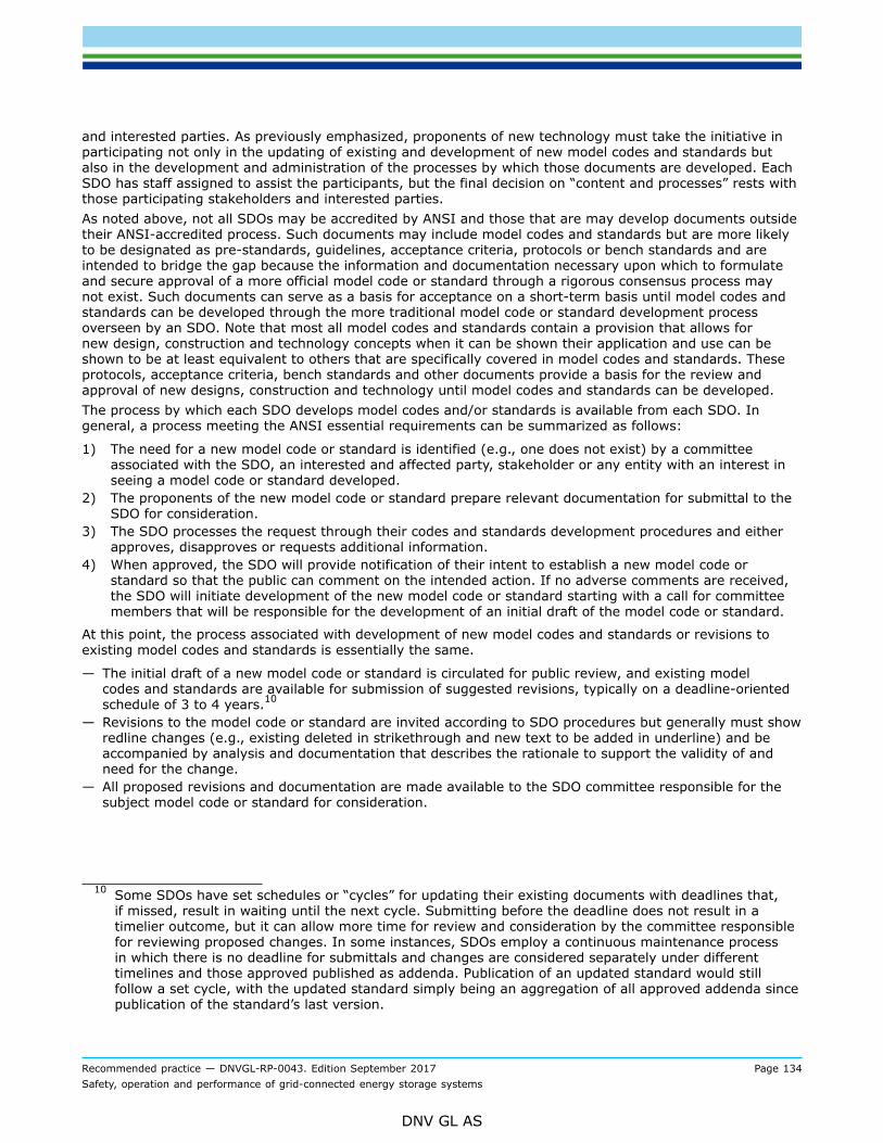
Recommended practice — DNVGL-RP-0043. Edition September 2017 Page 134Safety, operation and performance of grid-connected energy storage systems
DNV GL AS
and interested parties. As previously emphasized, proponents of new technology must take the initiative inparticipating not only in the updating of existing and development of new model codes and standards butalso in the development and administration of the processes by which those documents are developed. EachSDO has staff assigned to assist the participants, but the final decision on “content and processes” rests withthose participating stakeholders and interested parties.As noted above, not all SDOs may be accredited by ANSI and those that are may develop documents outsidetheir ANSI-accredited process. Such documents may include model codes and standards but are more likelyto be designated as pre-standards, guidelines, acceptance criteria, protocols or bench standards and areintended to bridge the gap because the information and documentation necessary upon which to formulateand secure approval of a more official model code or standard through a rigorous consensus process maynot exist. Such documents can serve as a basis for acceptance on a short-term basis until model codes andstandards can be developed through the more traditional model code or standard development processoverseen by an SDO. Note that most all model codes and standards contain a provision that allows fornew design, construction and technology concepts when it can be shown their application and use can beshown to be at least equivalent to others that are specifically covered in model codes and standards. Theseprotocols, acceptance criteria, bench standards and other documents provide a basis for the review andapproval of new designs, construction and technology until model codes and standards can be developed.The process by which each SDO develops model codes and/or standards is available from each SDO. Ingeneral, a process meeting the ANSI essential requirements can be summarized as follows:
1) The need for a new model code or standard is identified (e.g., one does not exist) by a committeeassociated with the SDO, an interested and affected party, stakeholder or any entity with an interest inseeing a model code or standard developed.
2) The proponents of the new model code or standard prepare relevant documentation for submittal to theSDO for consideration.
3) The SDO processes the request through their codes and standards development procedures and eitherapproves, disapproves or requests additional information.
4) When approved, the SDO will provide notification of their intent to establish a new model code orstandard so that the public can comment on the intended action. If no adverse comments are received,the SDO will initiate development of the new model code or standard starting with a call for committeemembers that will be responsible for the development of an initial draft of the model code or standard.
At this point, the process associated with development of new model codes and standards or revisions toexisting model codes and standards is essentially the same.
— The initial draft of a new model code or standard is circulated for public review, and existing modelcodes and standards are available for submission of suggested revisions, typically on a deadline-orientedschedule of 3 to 4 years.10
— Revisions to the model code or standard are invited according to SDO procedures but generally must showredline changes (e.g., existing deleted in strikethrough and new text to be added in underline) and beaccompanied by analysis and documentation that describes the rationale to support the validity of andneed for the change.
— All proposed revisions and documentation are made available to the SDO committee responsible for thesubject model code or standard for consideration.
10 Some SDOs have set schedules or “cycles” for updating their existing documents with deadlines that,if missed, result in waiting until the next cycle. Submitting before the deadline does not result in atimelier outcome, but it can allow more time for review and consideration by the committee responsiblefor reviewing proposed changes. In some instances, SDOs employ a continuous maintenance processin which there is no deadline for submittals and changes are considered separately under differenttimelines and those approved published as addenda. Publication of an updated standard would stillfollow a set cycle, with the updated standard simply being an aggregation of all approved addenda sincepublication of the standard’s last version.

Recommended practice — DNVGL-RP-0043. Edition September 2017 Page 135Safety, operation and performance of grid-connected energy storage systems
DNV GL AS
— The responsible committee undertakes a review of the submitted materials and determines which oneswill comprise the revisions to the model code or standard.11
— All proposed changes, either from an SDO committee or as submitted by the public, are made availablefor public review and comment.
— Public comments and recommended revisions to the proposed changes are accepted by the SDO andconsidered by the responsible committee.
— The committee will communicate with those submitting proposed changes as to the disposition of thechange. The submitters are given an opportunity for further dialogue and revision to the proposed changeto achieve agreement on the outcome of and final language associated with the change.
— Revisions to the proposed changes may be made available for additional public comment to find acommon ground for criteria in the model code or standard.
— Based on any additional public input, the committee or SDO membership will consider the changes andpublic input and vote a disposition on each change.
— Proposed changes voted for approval, along with the existing unchanged text of the model code orstandard, would comprise the next edition of the model code or standard or, in the case of new modelcodes or standards, the first edition.
— Stakeholders who participated in the process have the right of appeal to the SDO if they feel the outcomeis incorrect because procedures were not followed. If the appeal is upheld, the revision is sent back to theresponsible committee for additional work instead of being included in the model code or standard.
Section [B.3] covers some of the U.S. model codes and standards that are relevant to energy storagesystems. Through the process described above those model codes and standards are developed and thenupdated on a regular basis to address new technology and to respond to new information and experiences.Those model codes and standards are then available for adoption throughout the U.S. and in other countries,eliminating the need for those adopting those documents to have to each separately and in parallel conductthe same developmental effort as described above.
B.2.2.5 Adoption of voluntary sector model codes and standardsBeyond the state and local legislative, regulatory and program initiatives previously discussed state, local,territorial and tribal governments, predominately through rules and regulations as opposed to directly inlegislation, have the authority to develop, adopt and/or enforce provisions related to ‘health, life safety andwelfare’. In addition, they may have the authority to also cover energy and environmental issues through‘green’ codes and standards.After model codes or standards are developed in the voluntary sector, as discussed in section [B.2.2.4]above, they are available for adoption. Adoption is simply a decision by any decision-making entity that amodel code or standard will be used, implemented, complied with and satisfied. Adoption makes compliancewith the model codes or standards that are adopted mandatory and, as such, makes the document muchmore relevant than if it were advisory but not required.Adoption can occur in many ways that include the following:
— Legislative or regulatory action by a governmental entity (federal, state, local, Indian Tribe) as amandatory requirement in all cases or as a condition for program participation or funding.12
— Action by a utility under its operation as controlled by a Public Utility Commission (PUC) and acting asthe AHJ for systems on the grid side of the meter or simply as the entity connecting to an ESS on thecustomer side of the meter.
— A requirement by an insurance carrier as a condition for insurance coverage.
11 Note that in some instances, the changes developed for public comment must go through an SDOcommittee; at other times, all suggested changes to a model code or standard may be accepted,discussed at public hearings and subsequently receive recommendation from the responsible committeeon the disposition of the change subject to additional public comment.
12 Mandatory requirements would generally be considered building regulations. Conditional requirementswould be for instance compliance as a condition for a facility securing approval under a specific financingprogram or accreditation to participate in a federal program such as Medicare or Medicaid.
Recommended practice — DNVGL-RP-0043. Edition September 2017 Page 136Safety, operation and performance of grid-connected energy storage systems
DNV GL AS
— As a condition for licensing (e.g., a state contractor licensing board that adopts and applies particulartechnical requirements and compliance with those as a condition for licensure).
— By reference in building specifications issued by a building owner/developer or financial institution backinga project.
— By anyone considering the application and use of energy storage that in the absence of any other meansof adoption elects to apply model codes or standards to their project (e.g., self- adoption).
Federal agencies also have the authority to adopt and enforce codes and standards through rules, regulationsand program requirements that impact the built environment, which includes EES. Federal agencies thatown and/or lease property have and exercise the authority to adopt and enforce rules and regulationscovering the built environment under their control. This includes, but is not limited to the General ServicesAdministration, Department of Defence, Department of Justice Bureau of Prisons, Archives and RecordsAdministration, National Aeronautics and Space Administration, Department of Energy and the Architect ofthe Capitol. Each agency will have responsibility for the buildings they own as well as private sector buildingsthey lease and occupy. In addition, agencies may require compliance with certain rules and regulations asa condition for entities to participate in programs operated by the agency. An example of this situation isthe adoption of rules and regulations for construction and operation of health care facilities by the Healthand Human Services Centers for Medicare and Medicaid Services (HHS CMS) as a condition for participatingin those programs. As such, the agency does not own or lease the property, but instead the owners andoperators of the property must comply with their requirements in order to provide services covered underHHS CMS. In most all cases the requirements adopted and applied by any agency in the situations describedabove will be based on voluntary sector codes, standards and guidelines as described in section [B.2.2.4].with possible amendments to increase the scope of the adopted documents and/or adjust the technicaland/or administrative requirements to better address their specific and unique needs. With respect toenergy storage systems it is anticipated that the codes, standards and guidelines as described in section[B.2.2.4] would apply to the federal agency scenarios described in this section. Further specifics on howthose documents are adopted and applied by a particular agency would have to be secured from that agency,many of which would be delineated in the U.S. Code of Federal Regulations (which is segregated by federalagency).When legally adopted through legislative or regulatory action, model codes or standards are consideredregulations. Their adoption through other means is more likely to be considered as rules, specifications orsome other term that distinguishes the adoption from a legislative or regulatory action by government (e.g.,law).The federal government has traditionally undertaken the adoption of model codes or standards as regulationsgoverning certain federal buildings and facilities as covered above. State government also has similarauthority for state owned and funded buildings as do local, territorial and tribal government. With respectto private sector construction, some states have authority to adopt model codes or standards as regulationsthat apply throughout the state. In the majority of cases in which there is a state-mandated preemptiveregulation, the adoption process is legislatively granted to one or more agencies instead of being addresseddirectly by the legislature.13 In turn, those agencies will use a specific and unique state regulatory processto adopt and administer their regulations. In states without such authority, the authority is delegated to thelocal government, who then use their own specific and unique local legislative or regulatory process. Indiantribes are autonomous and not under the jurisdiction of any federal, state or local legislative or regulatoryaction and as such control what regulations they adopt. It is important also to recognize that the authority(or not) of federal, state and local government is likely to vary by subject, scope and many other factors. Forinstance, there may be a statewide set of requirements for only public buildings or only a statewide electricalcode; the remainder of what is not covered by the state is then subject to whatever local governmentchooses to regulate (or not).
13 Typically, the involvement of an elected body in essentially writing construction requirements is notencountered for many reasons, one being every time a revision is desired it must go through thelegislative process. For this reason, legislative bodies will generally direct what they want (e.g., astatewide code) and then authorize and empower governmental agencies to develop and adopt therequirements. In some instances, however, the legislature does retain oversight and votes to confirmwhat the regulatory agency(s) have adopted.

Recommended practice — DNVGL-RP-0043. Edition September 2017 Page 137Safety, operation and performance of grid-connected energy storage systems
DNV GL AS
In the case of governmental regulation, it is important to be active in the adoption process because theadopting entities (legislative or regulatory) may not necessarily adopt the most recent model codes orstandards or upon adoption may include amendments that can either strengthen or update the requirementsor weaken them. Engagement in this process can foster the more timely adoption of current model codes orstandards and also can minimize the approval of amendments that would adversely impact ESS. In addition,where older versions of model codes or standards have been adopted, amendments can be submitted to atleast update what has been adopted to more appropriately address energy storage system safety. Becausestate and local governmental adoptions generally occur on a 3-year or more cycle (similar to that with modelcodes or standards development), it is equally important to recognize state and local schedules associatedwith and opportunities for adoption. Adoptions by a contractor licensing board could also be consideredregulatory, the mechanism for ensuring compliance being licensing of contractors doing electrical workas opposed to not approving an ESS installation through a more traditional plan review and constructioninspection process.Outside legislation or regulation there are other adoption mechanisms whose timing is not as structuredbut should still be addressed. Utilities would adopt standards and possibly model codes to govern theacceptability of an ESS and its installation on the grid side of the meter or possibly for an ESS they own andoperate on public or private property on the customer side of the meter. Those would not likely be consideredregulations but instead specifications and guidelines as to what those providing an ESS to the utility mustsatisfy as a condition for doing what is contracted for. The utility would be able to undertake adoption at anytime. This is also the case with insurance carriers and owners/developers who would be looking to updatespecifications or other criteria they place on those they insure or who do design and construction work forthem. Note also model codes and standards may be adopted by multiple agencies and concurrently applyto a project. For instance, a federal agency can officially adopt specific model codes and standards for theirprojects, but a set of state regulations such as a state building and fire code covering the same subject mightalso apply but could differ with what the federal agency has adopted.
B.3 List of normative and informative referencesThe following model codes, standards, guidelines, and similar documents can be applicable to EES systems,depending on technology type, application, location and other factors. It is recommended to go throughall previous sections of this document and check the references specifically mentioned there for the topicsaddressed. For any remaining topics, references in the comprehensive list in the subsections below (includingall previously mentioned references for comprehensiveness) may be useful and/or applicable.
B.3.1 Stationary energy storageB.3.1.1 System level - including installation
— IEC 62619 (2017): Secondary cells and batteries containing alkaline or other non-acid electrolytes –Safety requirements for large format secondary lithium cells and batteries for use in industrial applications
— IEC 62620 (2014): Secondary cells and batteries containing alkaline or other non-acid electrolytes – Largeformat secondary lithium cells and batteries for use in industrial applications
— IEC 61427 -1: Secondary cells and batteries for renewable energy storage – General requirements andmethods of test – Part 1: Photovoltaic off-grid application
— IEC 61427-2: Secondary cells and batteries for renewable energy storage – General requirements andmethods of test – Part 2: on-grid applications
— IEEE 1375: IEEE Guide for the Protection of Stationary Battery Systems— IEEE 1491: IEEE Guide for Selection and Use of Battery Monitoring Equipment in Stationary Applications— IEEE 1679: IEEE Recommended Practice for the Characterization and Evaluation of Emerging Energy
Storage Technologies in Stationary Applications— IEEE 484: Recommended Practice for Installation and Design of Vented Lead-Acid Batteries for Stationary
Applications— IEEE P2030.3: Standard for Test Procedures for Electric Energy Storage Equipment and Systems for
Electric Power Systems Applications

Recommended practice — DNVGL-RP-0043. Edition September 2017 Page 138Safety, operation and performance of grid-connected energy storage systems
DNV GL AS
— IEC TC 120 working documents: Electrical Energy Storage Systems – IEC 62933 series:— IEC 62933-1 (under development): Electrical energy storage (EES) systems – Part 1: Terminology— IEC 62933-2-1 (under development): Electrical Energy Storage (EES) systems – Part 2-1: Unit
parameters and testing methods – General specification— IEC 62933-3-1 (under development): Electrical Energy Storage (EES) systems – Part 3-1: Planning and
installation – General specification— IEC TS 62933-4-1 (under development): Electrical Energy Storage (EES) systems – Part 4-1: Guidance on
environmental issues— IEC TS 62933-5-1 (under development): Electrical Energy Storage (EES) systems – Part 5-1: Safety
considerations related to grid integrated electrical energy storage (EES) systems— IEC 62933-5-2 (under development): Electrical Energy Storage (EES) systems – Part 5-2: Safety
considerations related to grid integrated electrical energy storage (EES) systems – Batteries— ANSI/CAN/UL-9540: 2016 Standard for Safety, Energy Storage Systems and Equipment (under
continuous maintenance) – this standard is used to test and then certify energy storage systems as to thesafety.
— 2018 International Fire Code, International Code Council— 2018 International Building Code, International Code Council— 2018 International Residential Code, International Code Council— NFPA 1-2017 Fire Code— NFPA 70-2017 National Electrical Code— NFPA 855, Standard for the Installation of Energy Storage Systems (first draft under development)— ANSI/IEEE Std C2-2007 TM: National Electrical Safety Code
B.3.1.2 Battery cell level - general
— IEC 60622: Secondary Cells and Batteries containing Alkaline or Other non-acid Electrolytes – Sealed NiCdPrismatic Rechargeable Cells
— IEC 60623: Secondary Cells and Batteries containing Alkaline or Other non-acid Electrolytes – VentedNiCd Prismatic Rechargeable Cells
— IEC 60896-11: Stationary Lead Acid Batteries Part 11: Vented Types – General Requirements and Methodsof Tests
— IEC 60896-21: Stationary Lead Acid Batteries Part 21: Valve Regulated Types – Methods of tests— IEC 60896-22: Stationary Lead Acid Batteries Part 22: Valve Regulated Types – Requirements— IEC 62133-1 and -2 (2017): Secondary cells and batteries containing alkaline or other non-acid
electrolytes – Safety requirements for portable sealed secondary cells, and for batteries made from them,for use in portable applications, reverse charge safety
— IEEE 1184: IEEE Guide for Batteries for Uninterruptable Power Supply Systems Performance— IEEE 1361: IEEE Guide for Selection, Charging, Test, and Evaluation of Lead Acid Batteries used in Stand
Alone PV Systems— IEEE 1660: IEEE Guide for Application and Management of Stationary Batteries Used in Cycling Service— IEEE 1661: IEEE Guide for Test and Evaluation of Pb-Acid Batteries used in PV Hybrid Power Systems— UL 1642: Lithium Batteries— UL 1973: Batteries for Use in Light Electric Rail (LER) Applications and Stationary Applications— UL 1974: Evaluation for Repurposing of Batteries (first edition under development)— UL 2054: Household and Commercial Batteries— UN 3292: Batteries, Containing Sodium
B.3.1.3 Battery cell level - electric vehicle applications
— IEC 62660-1: Secondary lithium-ion cells for the propulsion of electric road vehicles – Part 1: Performancetesting
— IEC 62660-2 (2010): Secondary lithium-ion cells for the propulsion of electric road vehicles – Part 2:Reliability and abuse testing

Recommended practice — DNVGL-RP-0043. Edition September 2017 Page 139Safety, operation and performance of grid-connected energy storage systems
DNV GL AS
— IEC 62660-3 (under development): Secondary lithium-ion cells for the propulsion of electric road vehicles– Part 3: Safety requirements
— SAE J2185: Life Test for Heavy-Duty Storage Batteries— SAE J2288: Life Cycle Testing of Electric Vehicle Battery Modules— SAE J240: Life Test for Automotive Storage Batteries— SAE J2464: Electric and Hybrid Electric Vehicle Rechargeable Energy Storage System (RESS) Safety and
Abuse Testing— SAE J2929: Electric and Hybrid vehicle propulsion battery system safety standard – lithium-based
rechargeable cells— UL 2580: Batteries for use in electric vehicles
B.3.2 Electrical energy components and technologies— UL 810A: Electrochemical Capacitors— IEC 62813 Lithium-ion capacitors for use in electric and electronic equipment – Test methods for electrical
characteristics— Flow batteries – Guidance on the specification, installation and operation, CENELEC Workshop Agreement,
CWA 50611, April 2013— IEC 62932-1 (under development): Secondary Cells and Batteries of the Flow Type: Flow Batteries –
Guidance on the Specification, Installation and Operation— IEC 62932-2-1 (under development): Flow batteries – General requirement and test method of vanadium
flow batteries— IEC 62932-2-2 (under development): Flow Battery Technologies – Safety— IEC 60034-1: Rotating electrical machines – Part 1: Rating and performance— IEC 11439 Gas Cylinders-High pressure cylinders for the on-board storage of natural gas as a fuel for
automotive vehicles— ASME Boiler and Pressure Vessel Code Section VIII: Rules for Construction of Pressure Vessels— EN 13445 Unfired Pressure Vessels (harmonized with the Pressure Equipment Directive (97/23/EC)
B.3.3 Performance— Functional Requirements for Electric Energy Storage Applications on the Power System Grid, Electric Power
Research Institute (EPRI)— PNNL 22010-rev 2: Protocol for Uniformly Measuring and Expressing Performance of Energy Storage
Systems (2016)
B.3.4 SafetyB.3.4.1 Risk assessment methodologies
— IEC 60812: Analysis techniques for system reliability – Procedure for failure modes and effects analysis(FMEA)
— IEC 61025: Fault Tree Analysis (FTA)— IEC 61882: 2001 – Hazard and operability studies (HAZOP studies) – Application guide— MIL-STD-1692A: Military Standard Procedures for performing a failure mode, effects and criticality
analysis— ISO 17776: Petroleum and natural gas industries – Offshore production installations -Guidelines on tools
and techniques for hazard identification and risk assessment— UN3508— ISO 12100: Safety of machinery – general principles for design – risks assessment and risk reduction
Recommended practice — DNVGL-RP-0043. Edition September 2017 Page 140Safety, operation and performance of grid-connected energy storage systems
DNV GL AS
B.3.4.2 Transport safety
— UN 38.3 (United Nations): UN Manual of Tests and Criteria for the Transportation of Dangerous Goods,Lithium Battery Testing Requirements
— IEC 62281 (2011): Safety of primary and secondary lithium cells and batteries during transport. (Similarto UN38.8)
— IMDG (IMO): International Maritime Dangerous Goods (IMDG) Code— ICAO/IATA DGR: Dangerous goods regulations (DGR, 54th edition)— UN 3508, Capacitor, asymmetric (with an energy storage capacity greater than 0.3 Wh)
B.3.4.3 Safety systems
— IEC 61508 (all parts): Functional safety of electrical/electronic/programmable electronic safety-relatedsystems
— IEC 62061: Safety of Machinery – Functional safety of safety-related electrical, electronic andprogrammable electronic control systems
— IEC 61511-1: Safety instrumented systems for the process industry sector – Part 1: Framework,definitions, system hardware and software requirements
— IEC 62040-1: Uninterruptible power systems (UPS) –Part 1-1: General and safety requirements for UPSused in operator access areas
— IEC 62040-1-2: Uninterruptible power systems (UPS) –Part 1-2: general and safety requirements for UPSinstalled in restricted access locations
— SAE J1495: Test Procedure for Battery Flame Retardant Venting Systems— ISO 13849-1: Machine safety
B.3.4.4 Operational safety
— IEC 62485 -1 (under development): Safety requirements for secondary batteries and battery installations– Part 1: General safety information
— IEC 62485-2 (2010): Safety requirements for secondary batteries and battery installations – Part 2:Stationary batteries
— IEC 62485-3 (2010): Safety requirements for secondary batteries and battery installations – Part 3:Traction batteries
— IEC 62485-5 (under development): Safety requirements for secondary batteries and battery installations– Part 5: Lithium-ion batteries for stationary applications
— ISO 12405-3 (under development): Electrically propelled road vehicles – Test specification for Lithium-iontraction battery packs and systems – Part 3: Safety performance requirements
— UL Subject 9540 (under development)Safety for Energy Storage Systems and Equipment
B.3.4.5 Specific hazards
— IEC 60695-1-11/Ed1 2010-06: – Fire hazard testing – Part 1-11: Guidance for assessing the fire hazard ofelectrochemical products – Fire hazard assessment.
— IEC 61140 / Ed 3.1:- Protection against electric shock – Common aspects for installation and equipment— IEC 60364-4-41: Low-voltage electrical installations– Part 4: Protection for safety –Installation,
maintenance and personnel— IEEE 450: IEEE Recommended Practice for Maintenance, Testing, and Replacement of Vented Lead Acid
Batteries for Stationary Applications— IEEE 937: IEEE Recommended Practice for Installation and Maintenance of Lead-Acid Batteries for
Photovoltaic (PV) Systems— IEEE 1188: IEEE Recommended Practice for Maintenance, Testing, and Replacement of Vented Lead Acid
Batteries for Stationary Applications— IEEE 1106: IEEE Recommended Practice for Installation, Maintenance, Testing, and Replacement of
Vented NiCd Batteries for Stationary Applications

Recommended practice — DNVGL-RP-0043. Edition September 2017 Page 141Safety, operation and performance of grid-connected energy storage systems
DNV GL AS
— IEEE 1657: IEEE Recommended Practice for Personnel Qualifications for Installation and Maintenance ofStationary Batteries
B.3.5 Further relevant standardisation documentsB.3.5.1 Electrical equipment
— ANSI C57.12.25-1990: Pad-Mounted Transformer Requirements— ANSI C57.12.28-2005: Pad-Mounted Equipment Enclosure Integrity— IEC 61850: Standard on the Design of Electrical Substation Automation— IEEE 519-1992TM: IEEE Recommended Practices and Requirements for Harmonics Control in Electrical
Power Systems— NIST Framework and Roadmap for Smart Grid Interoperability Standards, Release 1.0, National Institute
of Standards and Technology (NIST) Special Publication 1108, January 2010— Smart Energy Profile (SEP) Standard System for Communication with Demand Side Management
Equipment— DNV SFC No. 2.4: DNV GL Environmental Test Specifications for Instrumentation and Automation
Equipment— IEC 60529: Ingress protection (IP)— IEC 60730-1 (2013): Automatic electrical controls (for household and similar use) – Part 1: General
requirements (Annex H: Requirements for Electronic Controls)
B.3.5.2 Electromagnetic compatibility and surge withstand requirements
— FCC Sections 15.109 and 15.209: Federal Communications Commission, Code of Federal Regulations,Radiated Emission Limits, General Requirements
— IEEE C37.90.2-2004 TM: IEEE Standard Withstand Capability of Relay Systems to RadiatedElectromagnetic Interference from Transceivers
— IEEE C37.90.1-2002 TM: IEEE Standard for Surge Withstand Capability (SWC) Tests for Protective Relaysand Relay Systems (ANSI)
— IEEE C62.41-1991(R 1995) TM: IEEE Recommended Practice on Surge Voltages in Low-Voltage AC PowerCircuits
— IEEE C62.41.1-2002 TM: IEEE Guide on the Surges Environment in Low-Voltage (1000 V and Less) ACPower Circuits
— IEEE C62.41.2-2002 TM: IEEE Recommended Practice on Characterization of Surges in Low-Voltage (1000V and Less) AC Power Circuits
— IEEE C62.45-2002 TM: IEEE Recommended Practice on Characterization of Surges in Low-Voltage (1000 Vand Less) AC Power Circuits
— IEC EN 61000-4-2, Electromagnetic compatibility (EMC)- Part 4-2: Testing and measurement techniques –Electrostatic discharge immunity test
— IEC EN 61000-4-3, Electromagnetic compatibility (EMC)- Part 4-3: Testing and measurement techniques –Radiated, radio-frequency, electromagnetic field immunity test
— IEC EN 61000-4-4, Electromagnetic compatibility (EMC) – Part 4-4: Testing and measurement techniques– Electrical fast transient/burst immunity test
— IEC EN 61000-4-5, Electromagnetic compatibility (EMC) – Part 4-5: Testing and measurement techniques– Surge immunity test
— IEC EN 61000-4-6, Electromagnetic compatibility (EMC) – Part 4-6: Testing and measurement techniques– Immunity to conducted disturbances, induced by radio-frequency fields
— IEC EN 61000-4-7, Electromagnetic compatibility (EMC) – Part 4-7: Testing and measurement techniques– General guide on harmonics and interharmonics measurements and instrumentation, for power supplysystems and equipment connected thereto
— IEC EN 61000-4-8, Electromagnetic compatibility (EMC) – Part 4-8: Testing and measurement techniques– Power frequency magnetic field immunity test

Recommended practice — DNVGL-RP-0043. Edition September 2017 Page 142Safety, operation and performance of grid-connected energy storage systems
DNV GL AS
— IEC EN 61000-4-9, Electromagnetic compatibility (EMC) – Part 4-9: Testing and measurement techniques– Pulse magnetic field immunity test
— IEC EN 61000-4-11, Electromagnetic compatibility (EMC) – Part 4-11: Testing and measurementtechniques – Voltage dips, short interruptions and voltage variations immunity tests
B.3.5.3 Interconnection of distributed generation sources
— IEC/TS 62257-5: Recommendations for small renewable energy and hybrid systems for ruralelectrification – Part 5: Protection against electrical hazards
— IEC/TS 62257-8-1: Recommendations for small renewable energy and hybrid systems for ruralelectrification – Part 8-1: Selection of batteries and battery management systems for stand-aloneelectrification systems – Specific case of automotive flooded lead-acid batteries available in developingcountries
— IEC/TS 62257-9-1: Recommendations for small renewable energy and hybrid systems for ruralelectrification – Part 9-1: Micropower systems
— IEC/TS 62257-9-2: Recommendations for small renewable energy and hybrid systems for ruralelectrification – Part 9-2: Microgrids
— prEN 50438 (under development): Requirements for the connection of micro-generators in parallel withpublic low-voltage distribution networks
— IEEE 1547-2003: IEEE Standard for Interconnecting Distributed Resources with Electric Power Systems— EN 50272: Safety requirements for secondary batteries and battery installations – Part 2: Stationary
batteries— IEEE P1547.1: Standard For Conformance Test Procedures for Equipment Interconnecting Distributed
Resources with Electric Power Systems— IEEE P1547.2: Application Guide for IEEE Std. 1547, Standard for Interconnecting Distributed Resources
with Electric Power Systems— IEEE P1547.3: Guide for Monitoring, Information Exchange, and Control of Distributed Resources
Interconnected With Electric Power Systems— IEEE P1547.4: Draft Guide for Design, Operation, and Integration of Distributed Resource Island Systems
with Electric Power Systems— IEEE P1547.5: Draft Technical Guidelines for Interconnection of Electric Power Sources Greater than 10
MVA to the Power Transmission Grid— IEEE P1547.6: Draft Recommended Practice For Interconnecting Distributed Resources With Electric Power
Systems Distribution Secondary Networks— IEEE P1547.7: Draft Guide to Conducting Distribution Impact Studies for Distributed Resource
Interconnection— UL 1741: UL Standard for Inverters, Converters, Controllers and Interconnection System Equipment for
Use With Distributed Energy Resources— UL 3001: Distributed Energy Generation and Storage Systems— UL 1547: Standard for Interconnecting Distributed Resources with Electric Power Systems (field test)— UL 1741: Inverters, Converters, Controllers and Interconnection System Equipment for Use With
Distributed Energy Resources— IEC 62786 (under development): Demand Side Energy Resources Interconnection with the Grid— IEC 62477-1:2012, Safety requirements for power electronic converter systems and equipment – Part 1:
General;— IEC TS 62749:2015, Assessment of power quality – Characteristics of electricity supplied by public
networks.
B.3.5.4 Electrical energy storage systems
— Community Energy Storage (CES), Storage Unit Functional Specification, Revision 2.2, American ElectricPower, 12/09/2009
— ATIS-0600330: Valve Regulated Lead Acid Batteries Used in the Telecommunications Environment (leadacid battery cells and modules, operation aspects)

Recommended practice — DNVGL-RP-0043. Edition September 2017 Page 143Safety, operation and performance of grid-connected energy storage systems
DNV GL AS
— UL 1778: Underwriters Laboratory’s Standard for Uninterruptible Power Systems (UPS) for up to 600VA.C.
— DNV Rules for classification of Ships / High Speed, Light Craft and Naval Surface Craft, Part 6, Chapter 28;January 2012.
— DNV GL Guideline for Large Maritime Battery Systems, March 2014— “Cell Level Risk Based Evaluation of Li-ion Batteries for Maritime, Transport, and Energy Storage
Applications” DNV GL, 2013
B.3.5.5 Cyber security
— IEC TS 62351-2:2008, Power systems management and associated information exchange – Data andcommunications security – Part 2: Glossary of terms;
— NERC CIP-002-3 (ver 3): Critical Cyber Asset Identification— NERC CIP-002-5.1 (ver 6): BES (Bulk Electronic Systems) Cyber System Categorization— NERC CIP-003-6 (ver 6) Security Management Controls— NERC CIP-004-6 (ver 6): Personnel & Training— NERC CIP-005-5 (ver 6): Electronic Security Perimeters— NERC CIP-006-6 (ver 6): Physical Security of BES Cyber Assets— NERC CIP-007-6 (ver 6): Systems Security Management— NERC CIP-008-5 (ver 6): Incident Reporting and Response Planning— NERC CIP-009-6 (ver 6): Recovery Plans for BES Cyber Systems— NERC CIP-010-2 (ver 6): Configuration Change Management and Vulnerability Assessments— NERC CIP-011-2 (ver 6); Cyber Security – Information Protection— NIST Cybersecurity Framework (NIST CSF): Provide a policy framework of computer security for
organizations to assess and improve their ability to prevent, detect, and respond to cyber attacks— ISO/IEC 27001: Information security management systems – Requirements— ISO/IEC 27002: Code of practice for information security controls— ISO/IEC 27003: Information security management systems implementation guidance— ISO/IEC 27004: Information security management – Measurement— ISO/IEC 27005: Information security risk management— ISO/IEC 27006: Requirements for bodies providing audit and certification of information security
management systems— ISO/IEC 27007 Guidelines information security management systems auditing— ISO/IEC 27019: Information security management guidelines based on ISO/IEC 27002 for process control
systems specific to the energy utility industry— IEC 62351: Security standards— IEC 62351-1: Introduction— IEC 62351-2: Glossary— IEC 62351-3: Profiles including TCP/IP— IEC 62351-4: Profiles including MMS— IEC 62351-5: IEC 60870-5 and derivates— IEC 62351-6: IEC 61850 profiles— IEC 62351-12: Resilience and security recommendations for power systems with DER— IEC 62351-13: What security topics should be covered in standards and specifications— IEC 62351-14: Cyber security event logging (draft)— IEC 62351-90-1: Role Based Access Control (RBAC) Guidelines— IEC 62351-90-2: Deep packet inspection— IEC 62351-10: Security architecture guidelines for TC 57 systems— IEC 62351-100: Conformance testing— IEC 62351-100-1: Conformance test cases for the IEC 62351-5 and its companion standards for secure
data (draft)
Recommended practice — DNVGL-RP-0043. Edition September 2017 Page 144Safety, operation and performance of grid-connected energy storage systems
DNV GL AS
— IEC 62443-1-1: Concepts and models (published under review)— IEC 62443-1-2: Master glossary of terms and abbreviations (development)— IEC 62443-1-3: System security conformance metrics (planned)— IEC 62443-1-4: IACS security life-cycle and use-cases (planned)— IEC 62443-2-1: Requirements for an IACS security management system (published under review)— IEC 62443-2-2: Implementation guidance for an IACS security management systems (planned)— IEC 62443-2-3: Patch management in the IACS environment— IEC 62443-2-4: Requirements for IACS solution suppliers (planned)— IEC 62443-3-1: Security technologies for IACS (published under review)— IEC 62443-3-2: Security risk assessment and system design (development)— IEC 62443-3-3: System security requirements and security levels— IEC 62443-4-1: Product development requirements (development)— IEC 62443-4-2: Technical security requirements for IACS components (development)— DNVGL-RP-0496: Cyber security resilience management for ships and mobile offshore units in operation
(September 2016)
B.3.5.6 General
— IEC 60050 – International Electrotechnical Vocabulary – www.electropedia.org— PNNL-23618: Inventory of Safety Related Codes and Standards for Energy Storage Systems— PNNL-23578: Overview of Development and Deployment of Codes, Standards and Regulations Affecting
Energy Storage System Safety in the United States— DNV GL RP-A-203: DNV GL Recommended Practice for Technology Qualification— ANSI Z535–2002: Product Safety Signs and Labels— UL 263: Fire Tests of Building Construction and Materials— Standard System for the Identification of the Hazards of Materials for Emergency Response— U.S. Department of Transportation, Pipeline and Hazardous Materials Transportation Law (HMR; 49 CFR
Parts 171–180)— EC Regulation 1907/2006 Registration, Evaluation, Authorisation and Restriction of Chemicals (REACH)— Directive 2011/65 (ROHS): on the restriction of the use of certain hazardous substances in electrical and
electronic equipment— Directive 2006/66 (Battery Directive) on batteries and accumulators and waste batteries and
accumulators
B.4 Recommendations for storage systems regarding legalframeworks, regulations and standardsRegarding the regulation and legislation of storage devices, the main point is how storage devices areclassified. Since energy storage is able to provide several functions at a time, often a distinction is madebetween regulating and merchant storage assets. Regulated assets are somehow controlled by regulatingauthorities and are applied for grid quality improvements. In Europe governments have control over someassets through the TSOs and DSOs. Merchant assets are applied for profit rendering activities like the tradeof energy.Typical for storage devices is that their role is not always either in the regulated (frequency, voltage andbalance control) or merchant (arbitrage) sector. On the one hand, storage devices can enhance the powerquality and relieve constraints in the grid. These are typical tasks of the TSO/DSO. On the other hand, thesame device can be used for merchant activities simultaneously. In that case the question is how to allocatethe benefits of storage resources when they are capable of bridging multiple roles and what the role of theTSO/DSO should be.In most European countries TSOs/DSOs are not allowed to deploy commercial activities. Supplying electricityto the grid, for example from storage, is seen as a commercial activity and thus there is a large barrier forTSOs/DSOs to engage in electricity storage.

Recommended practice — DNVGL-RP-0043. Edition September 2017 Page 145Safety, operation and performance of grid-connected energy storage systems
DNV GL AS
The main regulatory challenge for the implementation of storage systems is building up a European-levelenergy market and a common balancing market.Ownership of the future energy storage systems whatever the location and the grid connection (transmissionor distribution): should storage be owned by market parties or system/grid operators?
Guidance note:How could the regulatory framework be adjusted to integrate storage better in the supply chain?The regulatory framework should aim to create an equal level playing field for cross-border trading of electricity storage.
— The regulatory framework needs to provide clear rules and responsibilities concerning the technical modalities and the financialconditions of energy storage.
— It should address barriers preventing the integration of storage into markets. It should guarantee a level playing field vis-à-vis other sources of generation, exploit its flexibility in supplying the grid, stabilise the quality and supplies for RES generation.This will require new services and business opportunities linked to the deployment of electricity storage solutions.
— The framework should be technology neutral, ensuring fair competition between different technological solutions (not picking awinner).
— It should ensure fair and equal access to electricity storage independent of the size and location of the storage in the supplychain.
— It should ensure medium-term predictability in the investment and financial conditions (taxes, fees etc.), enabling favourableconditions for all kinds of storage, particularly micro-storage (home and district level).
Reference is made to the European Commission's DG ENER Working Paper The future role and challenges of Energy Storage (14January, 2013).
---e-n-d---o-f---g-u-i-d-a-n-c-e---n-o-t-e---

Cha
nges
- h
isto
ric
Recommended practice — DNVGL-RP-0043. Edition September 2017 Page 146Safety, operation and performance of grid-connected energy storage systems
DNV GL AS
CHANGES - HISTORICThere are currently no historical changes for this document.

About DNV GLDriven by our purpose of safeguarding life, property and the environment, DNV GL enablesorganizations to advance the safety and sustainability of their business. We provide classification,technical assurance, software and independent expert advisory services to the maritime, oil & gasand energy industries. We also provide certification services to customers across a wide rangeof industries. Operating in more than 100 countries, our experts are dedicated to helping ourcustomers make the world safer, smarter and greener.
SAFER, SMARTER, GREENER