document # date effective lat-td-04332-05 - …€¦ · document # date effective lat-td-04332-05...
TRANSCRIPT

Hard copies of this document are for REFERENCE ONLY and should not be considered the latest
revision.
Document # Date effective
LAT-TD-04332-05 06/22/2005
Author(s) Supersedes
Patrick Young Rev. 04 Brian Horwitz
Subsystem/Office
Electronics & DAQ Subsystem Document Title
Power Distribution Unit Electrical Interface Continuity and Isolation Test
Power Distribution Unit Electrical Interface Continuity and Isolation Test
Hard copies of this document are for REFERENCE ONLY and should not be considered the latest
revision. LAT-TD-04332-05 Page 2
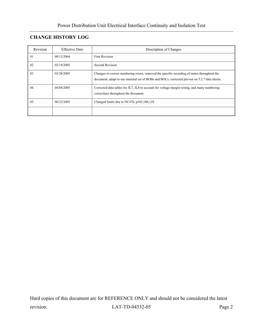
CHANGE HISTORY LOG
Revision Effective Date Description of Changes
01 08/13/2004 First Revision
02 02/14/2005 Second Revision
03 03/28/2005 Changes to correct numbering errors, removed the specific recording of mates throughout the
document, adapt to use minimal set of BOBs and BOCs, corrected pin-out on 5.2.7 data sheets.
04 04/04/2005 Corrected data tables for JL7, JL8 to account for voltage margin wiring, and many numbering
correctinos throughout the document.
05 06/22/2005 Changed limits due to NC476, p103,108,128

Power Distribution Unit Electrical Interface Continuity and Isolation Test
Hard copies of this document are for REFERENCE ONLY and should not be considered the latest
revision. LAT-TD-04332-05 Page 3
Table Of Contents
1. SCOPE .......................................................................................................................................... 6
1.1 Connection Procedures ......................................................................................................... 6
1.1.1 Electrical Interface Continuity and Isolation Test (EICIT) .......................................... 6
1.1.2 Safe To Mate (STM)..................................................................................................... 7
1.1.3 Stray Voltage Test (SVT) ............................................................................................. 7
2. ACRONYMS................................................................................................................................ 8
3. REFERENCES ............................................................................................................................. 9
3.1 Applicable Documents.......................................................................................................... 9
4. REQUIREMENTS...................................................................................................................... 10
4.1 General................................................................................................................................ 10
4.1.1 Specific Test Requirements (for the EICIT and SVT)................................................ 10
4.1.2 Specific Test Requirements ........................................................................................ 11
4.2 Interface Requirements ....................................................................................................... 12
4.3 Test Personnel and Descriptions......................................................................................... 13
4.4 Test Readiness Review (TRR) and Post Test Review (PTR) ............................................. 13
4.5 Environmental Conditions .................................................................................................. 14
4.6 Contamination Control........................................................................................................ 14
4.7 Handling and Transportation .............................................................................................. 15
4.8 ESD..................................................................................................................................... 15
4.9 Mate/Demate Connectors.................................................................................................... 15
4.10 Test Equipment ................................................................................................................... 15
4.11 Test Data and Review ......................................................................................................... 16

Power Distribution Unit Electrical Interface Continuity and Isolation Test
Hard copies of this document are for REFERENCE ONLY and should not be considered the latest
revision. LAT-TD-04332-05 Page 4
4.12 Flight Hardware Log Book ................................................................................................. 16
4.13 Nonconforming Test Data, Equipment and Software......................................................... 16
4.14 Redlining and Blacklining Documents ............................................................................... 16
4.15 Quality Assurance............................................................................................................... 17
4.15.1 Product Assurance Requirements ............................................................................... 17
4.16 Warnings, Cautions, and Notes........................................................................................... 18
4.17 Testing Safety ..................................................................................................................... 19
4.18 SLAC Safety, ES & H Manual ........................................................................................... 19
4.19 Crane Operations ................................................................................................................ 20
5. EICIT PROCEDURES ............................................................................................................... 21
5.1 Test Procedure Instructions/Information ............................................................................ 22
5.1.1 Test Overview............................................................................................................. 22
5.1.2 Applicability ............................................................................................................... 22
5.1.3 Test Sequence ............................................................................................................. 23
5.1.4 Test Equipment ........................................................................................................... 24
5.1.5 Participant List ............................................................................................................ 25
5.2 Power & Ground Continuity and Isolation Testing, Safe To Mate (Manual) .................... 26
5.2.1 Pre-Operation Verifications ........................................................................................ 26
5.2.2 PDU Interface Connections, JL-3 to JL-4................................................................... 28
5.2.3 PDU Interface Connections, JL-5 to JL-6................................................................... 31
5.2.4 PDU Interface Connections, JL-7 to JL-8................................................................... 34
5.2.5 PDU Interface Connections, JL-9 to JL-11................................................................. 37
5.2.6 PDU Interface Connections, JL-13 to JL-28............................................................... 41
Power Distribution Unit Electrical Interface Continuity and Isolation Test
Hard copies of this document are for REFERENCE ONLY and should not be considered the latest
revision. LAT-TD-04332-05 Page 5
5.2.7 PDU Interface Interconnections, JL-3/JL-4 to JL-7 and JL-8 .................................... 58
5.3 Signal Isolation and Controlled Resistance Testing (Manual) ........................................... 61
5.3.1 Pre-Operation Verifications ........................................................................................ 61
5.3.2 PDU Interface Connections, JL-3 to JL-4................................................................... 63
5.3.3 PDU Interface Connections, JL-5 to JL-6................................................................... 68
5.3.4 PDU Interface Connections, JL-7 to JL-8................................................................... 71
5.3.5 PDU Interface Connections, JL-9 to JL-11................................................................. 75
5.3.6 PDU Interface Connections, JL-13 to JL-28............................................................... 79
Appendix A (Data Sheets and Covers) ............................................................................................... 96
Appendix B (Connector Mate/Demate Log)..................................................................................... 131

Power Distribution Unit Electrical Interface Continuity and Isolation Test
Hard copies of this document are for REFERENCE ONLY and should not be considered the latest
revision. LAT-TD-04332-05 Page 6
1. SCOPE
This document establishes a procedure for verifying that flight hardware can be connected to other
instruments and other flight hardware elements using flight cables. This is the only such procedure to
be used for LAT integration and test.
Note: This document shall be considered subordinate to any Assembly and Inspection Data
Sheet (AIDS) that is used in conjunction with this testing process.
1.1 Connection Procedures
Often called Safe To Mate (STM) techniques, the safe connection process consists of the Electrical
Interface Continuity and Isolation Test (EICIT) and the Stray Voltage Test (SVT). The STM is a
subset of the EICIT and does not exist in stand alone documentation. The following usage principles
govern the safe connection process
1.1.1 Electrical Interface Continuity and Isolation Test (EICIT)
A process designed in response to NASA GEV-SE Para. 2.3.1, which states, "Before the integration
of an assembly, component, or subsystem into the next higher hardware assembly, electrical
interface tests shall be performed to verify that all interface signals are within acceptable limits of
applicable performance specifications." This process shall be performed at least once by the
subsystem supplier on each component, subassembly, or flight unit prior to initial application of
prime power. If no rework is performed on the assembly, it will be ready for integration into the
next assembly. If the component, subassembly, or flight unit has been reworked, it must undergo
another EICIT prior to application of prime power. Once testing is complete, the component,
subassembly, or flight unit shall be ready for integration in the next higher assembly.
This process is not repeated by LAT I&T. Subsystem results shall be sufficient to guarantee
equipment safety and conformance to requirements.

Power Distribution Unit Electrical Interface Continuity and Isolation Test
Hard copies of this document are for REFERENCE ONLY and should not be considered the latest
revision. LAT-TD-04332-05 Page 7
1.1.2 Safe To Mate (STM)
Safe to mate measurements are a subset of EICIT and are contained in EICIT procedures. STM tests
consist of like node continuity and power to ground line isolation measurements. Safe to mate
measurements will be performed as part of receiving tests on flight hardware after shipment or
exposure to uncontrolled mechanical environments. The STM will not be performed if a complete
EICIT has been performed.
This process is repeated by LAT I&T to ensure safety with the following exceptions:
CAL & TKR Subsystems will not receive STM testing by I & T.
1.1.3 Stray Voltage Test (SVT)
Stray voltage tests shall be performed at least once on interfaces that supply power. SVT shall be
performed at least once by the subsystem supplier on each component, subassembly, or flight unit
prior to integration with to any component, subassembly, flight unit, or EGSE. These checks are
limited to direct measurement of voltage with respect to equipment ground. Results shall be
compared with safe ranges based on the interface requirements of the mating component to ensure
that the mate does not harm mating component. Where an interface consists only of control signal,
and not power signals, the SVT is not required.
This process is repeated by LAT I&T to ensure safety with the following exceptions:
CAL & TKR Subsystems will not receive STM testing by I & T.

Power Distribution Unit Electrical Interface Continuity and Isolation Test
Hard copies of this document are for REFERENCE ONLY and should not be considered the latest
revision. LAT-TD-04332-05 Page 8
2. ACRONYMS
The following acronyms are used in this document:
AIDS Assembly and Inspection Data Sheet
BOB Break-Out-Box
BOC Break-Out-Cable
CAL Calorimeter
GASU Global trigger Anti-collision Spacecraft Unit
GCCC GLAST Calorimeter Cable Controller
ETech Electrical Technician
EUT Equipment Under Test
GLAST Gamma Ray Large Area Space Telescope
GTCC GLAST Tracker Cable Controller
LAT Large Area Telescope
MTech Mechanical Technician
PDU Power Distribution Unit
PTR Post Test Review
TC Test Conductor
TD Test Director
TEM Tower Electronics Module
TKR Tracker
TPS Tower Power Supply
TRR Test Readiness Review
QAE Quality Assurance Engineer
Power Distribution Unit Electrical Interface Continuity and Isolation Test
Hard copies of this document are for REFERENCE ONLY and should not be considered the latest
revision. LAT-TD-04332-05 Page 9
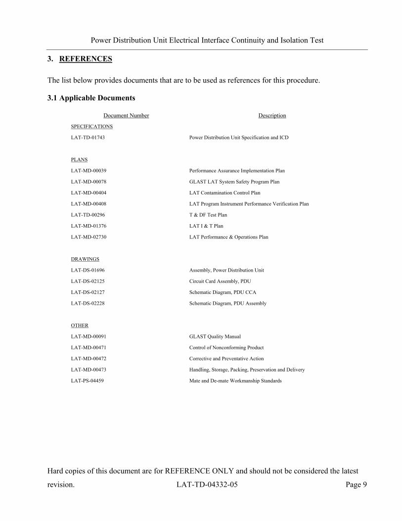
3. REFERENCES
The list below provides documents that are to be used as references for this procedure.
3.1 Applicable Documents
Document Number Description
SPECIFICATIONS
LAT-TD-01743 Power Distribution Unit Specification and ICD
PLANS
LAT-MD-00039 Performance Assurance Implementation Plan
LAT-MD-00078 GLAST LAT System Safety Program Plan
LAT-MD-00404 LAT Contamination Control Plan
LAT-MD-00408 LAT Program Instrument Performance Verification Plan
LAT-TD-00296 T & DF Test Plan
LAT-MD-01376 LAT I & T Plan
LAT-MD-02730 LAT Performance & Operations Plan
DRAWINGS
LAT-DS-01696 Assembly, Power Distribution Unit
LAT-DS-02125 Circuit Card Assembly, PDU
LAT-DS-02127 Schematic Diagram, PDU CCA
LAT-DS-02228 Schematic Diagram, PDU Assembly
OTHER
LAT-MD-00091 GLAST Quality Manual
LAT-MD-00471 Control of Nonconforming Product
LAT-MD-00472 Corrective and Preventative Action
LAT-MD-00473 Handling, Storage, Packing, Preservation and Delivery
LAT-PS-04459 Mate and De-mate Workmanship Standards

Power Distribution Unit Electrical Interface Continuity and Isolation Test
Hard copies of this document are for REFERENCE ONLY and should not be considered the latest
revision. LAT-TD-04332-05 Page 10
4. REQUIREMENTS
This section lists the requirements that shall be utilized during design, development, manufacture,
assembly, testing and storage.
4.1 General
The Performance Assurance Implementation Plan, LAT-MD-00039 shall be utilized to ensure that
the products produced by the GLAST LAT project intended for design qualification, flight and
critical ground support equipment usage meet the required levels of quality and functionality for
their intended purposes.
This procedure shall follow the LAT Program Instrument Performance Verification Plan LAT-MD-
00408 which details the LAT and its subsystem verification test flow.
The LAT T & DF Test Plan, LAT-TD-00296 shall be utilized to address the overall requirements at
engineering model, qualification and production level phases. This document defines the time period
from post circuit board fabrication until electronic box delivery to LAT Integration and Test.
Testing within this document shall conform to the requirements stated in LAT Performance and
Operations Test Plan LAT-MD-02730 for all testing that relates to LAT I & T.
4.1.1 Specific Test Requirements (for the EICIT and SVT)
This document verifies the following requirements:
Source Document Source Paragraph Test Paragraph Verification
LAT-MD-00408 7.1.1.2 5.2, 5.3 & 5.4 Test
LAT-MD-00408 7.3.1 5.2, 5.3 & 5.4 Test

Power Distribution Unit Electrical Interface Continuity and Isolation Test
Hard copies of this document are for REFERENCE ONLY and should not be considered the latest
revision. LAT-TD-04332-05 Page 11
4.1.2 Specific Test Requirements
Some of the tests in this document verify PDU requirements, as listed in the following table. The full
list of PDU requirements is listed in LAT-TD-01743.
This document verifies the following requirements:
Source Document
Source Paragraph
Test Paragraph
Verification Requirement
LAT-MD-00408 7.1.1.2 5.2, 5.3 & 5.4 Test
LAT-MD-00408 7.3.1 5.2, 5.3 & 5.4 Test
LAT-TD-01743 5.5 5.2 & 5.3 Test PDU Box shall have pin and connector assignments as
tabulated in LAT-TD-01743
LAT-TD-01743 5.5.1 5.2.2 Test Soft ground connection of 1.2Ω < R < 1.6Ω between
28V return path (from spacecraft) and PDU chassis
ground
LAT-TD-01743 5.5.1 5.2.2 Test Both PDUs are on the same chassis ground, which is also
board ground
LAT-TD-01743 5.5.6 5.2.4 Test A ground connection is provided at JL-7 and JL-8 (to the
GASU)
LAT-TD-01743 5.5.3 5.2.3 Test A ground connection is provided at JL-5 and JL-6 (to the
SIU)
LAT-TD-01743 5.5.7 5.3.2 Test A thermistor interface for each PDU is provided at JL3
(to the spacecraft)
LAT-TD-01743 5.5.7 5.3.2 Test A thermistor interface for each PDU is provided at JL4
(to the spacecraft)
LAT-TD-01743 5.5.7 5.2.7 Test 3 twisted pairs from JL-7 and 3 twisted pairs from JL-8
are presented at JL-3 (these are GASU temp and voltage
monitored by spacecraft)
LAT-TD-01743 5.5.7 5.2.7 Test 3 twisted pairs from JL-7 and 3 twisted pairs from JL-8
are presented at JL-4 (these are GASU temp and voltage
monitored by spacecraft)

Power Distribution Unit Electrical Interface Continuity and Isolation Test
Hard copies of this document are for REFERENCE ONLY and should not be considered the latest
revision. LAT-TD-04332-05 Page 12
4.2 Interface Requirements
This procedure shall verify conformance to requirements on the Power Distribution Unit electrical
interfaces. These requirements are contained in LAT-TD-01743, Power Distribution Unit
Specification and ICD.
Item Description Requirement
001 Grounding and shielding Grounding and shielding of the Power Distribution Unit shall conform to all
requirements of LAT-TD-01743, Power Distribution Unit Specification and ICD
002 Connector Pin Assignments The Power distribution Unit shall have the pin assignments per LAT-TD-01743
Power Distribution Unit Electrical Interface Continuity and Isolation Test
Hard copies of this document are for REFERENCE ONLY and should not be considered the latest
revision. LAT-TD-04332-05 Page 13
4.3 Test Personnel and Descriptions
Test personnel are described in GLAST LAT Integration and Test Subsystem Test Plan, LAT-MD-
01376. The test team members are defined with the following responsibilities:
4.4 Test Readiness Review (TRR) and Post Test Review (PTR)
The TRR and PTR are organizational meetings that shall be held at the appropriate times to inform
all parties about the testing that is to be accomplished and has been completed. The TRR and PTR
meetings are defined in the GLAST LAT Integration and Test Subsystem Test Plan, LAT-MD-
01376.

Power Distribution Unit Electrical Interface Continuity and Isolation Test
Hard copies of this document are for REFERENCE ONLY and should not be considered the latest
revision. LAT-TD-04332-05 Page 14
4.5 Environmental Conditions
Testing performed in accordance with this document shall conform to standard environmental test
conditions unless specific test requirements within this document exist. Standard Environmental test
conditions are as follows:
• Dynamic Mechanical Conditions: No load, at rest
• Temperature: 18.3 to 25.7°C
• Atmospheric Pressure: Uncontrolled local conditions
• Humidity: 30% to 50% RH for testing when the Calorimeter or Engineering Model (EM)
Calorimeters are present. For all other testing 30% to 60% RH is required.
This document shall follow the LAT Environmental Specification, LAT-SS-00778 for all testing
where non standard environments are required. The Environmental Specification defines the
thermal, vibration and on-orbit exposure design and test environments for the LAT instrument and
its subsystems.
4.6 Contamination Control
The Contamination Control Plan defines the overall contamination control requirements necessary to
establish hardware cleanliness for the GLAST LAT program. When work is performed at SLAC
follow LAT-MD-01386. When work is performed elsewhere follow LAT-MD-00404.

Power Distribution Unit Electrical Interface Continuity and Isolation Test
Hard copies of this document are for REFERENCE ONLY and should not be considered the latest
revision. LAT-TD-04332-05 Page 15
4.7 Handling and Transportation
This document shall follow the requirements found in the Handling, Storage, Package, Preservation
and Delivery document, LAT-MD-00473. This document establishes handling, storage, packaging
and transportation practices adequate to maintain the safety, reliability and quality of SLAC LAT
flight hardware items and achieve their damage free delivery to the place and time of ultimate use.
4.8 ESD
The CAL, TKR, T & DF Contamination Control Plan and the LAT Contamination Control Plan
define the ESD requirements for the GLAST LAT program. When work is performed at SLAC
follow LAT-MD-01386. When work is performed elsewhere follow LAT-MD-00404.
4.9 Mate/Demate Connectors
This document shall follow the requirements found in the Mate and Demate Workmanship Standard
LAT-PS-04459. The mate/demate process shall be followed for each and every connector mate. This
consists of a visual inspection of the interface, cleaning if required, and proper mating techniques.
4.10 Test Equipment
This document shall follow the requirements found in the LAT Program Instrument Performance
Verification Plan, LAT-MD-00408, which defines calibration, accuracy, substitutions, etc. for the
test equipment.

Power Distribution Unit Electrical Interface Continuity and Isolation Test
Hard copies of this document are for REFERENCE ONLY and should not be considered the latest
revision. LAT-TD-04332-05 Page 16
4.11 Test Data and Review
This document shall follow the requirements found in the LAT Program Instrument Performance
Verification Plan, LAT-MD-00408, which defines the test data sheets and details the personnel that
reviews test data. Test data shall be recorded on the data sheets that are found in Appendix A of this
document. The data sheets and any supporting data shall use a cover sheet that is found in Appendix
A of this document.
4.12 Flight Hardware Log Book
The LAT Program Instrument Performance Verification Plan, LAT-MD-00408 requires that a log of
hardware installation, software installation, power ON and mates/demates to flight connectors shall
be kept for each flight unit. The log book is part of the package that is deliverable to the customer.
4.13 Nonconforming Test Data, Equipment and Software
This document shall follow the requirements found in the Control of Nonconforming Product, LAT-
MD-00471. This document establishes methods to identify and control nonconforming product
developed by the LAT project team.
4.14 Redlining and Blacklining Documents
The users of this document shall follow the requirements found in the Redline/Blackline Engineering
Documents, LAT-MD-03474.
Power Distribution Unit Electrical Interface Continuity and Isolation Test
Hard copies of this document are for REFERENCE ONLY and should not be considered the latest
revision. LAT-TD-04332-05 Page 17
4.15 Quality Assurance
This document shall follow the requirements found in the Corrective and Preventative Action
document, LAT-MD-00472 and the GLAST Quality Manual, LAT-MD-00091 and LAT Program
Instrument Performance Verification Plan, LAT-MD-00408.
The Corrective and Preventative Action document establishes the method to be used to initiate,
implement, evaluate and record corrective and preventive actions. The GLAST Quality Manual
defines the methods implemented by the GLAST LAT project to ensure consistent quality of all
processes for procurement, design, development and production of flight hardware, flight software,
calibration and all associated ground support equipment interfacing with flight hardware and
software. The LAT Program Instrument Performance Verification Plan defines test configuration,
data sheets and review of test results.
4.15.1 Product Assurance Requirements
The QAE shall witness the initial test setup and validation operations. In the event of a failure a Non
Conformance Report (NCR) shall be written. The root cause and corrective action shall be identified
and there shall be QAE approval before the operation is continued. Any deviation from this
document requires approval from the QAE as well as the TC.

Power Distribution Unit Electrical Interface Continuity and Isolation Test
Hard copies of this document are for REFERENCE ONLY and should not be considered the latest
revision. LAT-TD-04332-05 Page 18
4.16 Warnings, Cautions, and Notes
The following SAFETY ALERTS are intended to create awareness of the potential safety hazards
and the steps that must be taken to avoid accidents. These same alerts are used throughout this
document to identify specific hazards that may endanger personnel and/or equipment.
Identification of every conceivable hazardous situation is impossible. Therefore, all personnel have
the responsibility to diligently exercise safe practices whenever exposed to this equipment.
WARNING: Indicates a potential hazardous situation which, if not avoided, could result in
death or injury.
CAUTION: Indicates a potential hazardous situation which, if not avoided, could result in damage
to equipment.
Note: Indicates a notification of information that is important, but not hazard related.
Power Distribution Unit Electrical Interface Continuity and Isolation Test
Hard copies of this document are for REFERENCE ONLY and should not be considered the latest
revision. LAT-TD-04332-05 Page 19
4.17 Testing Safety
This document shall follow the requirements found in the GLAST LAT System Safety Program
Plan, LAT-MD-00078. This document defines all phases of the LAT program including: design,
development, fabrication, handling, transportation, storage, test, assembly and operation.
4.18 SLAC Safety, ES & H Manual
This document shall follow the requirements found in the SLAC Environment, Safety, and Health
Manual, SLAC-I-720-0A29Z-001. This document defines the SLAC policy to support
environmental protection, health, and safety in the workplace.
WARNING: A hot work permit is required for work on or around open connectors/circuits
having:
∗ Voltage greater than 50V (AC or DC)
AND
∗ Current supply capability greater than 5mA
OR any circuit having
∗ Energy storage greater than 10 Joules (E=1/2CV²)

Power Distribution Unit Electrical Interface Continuity and Isolation Test
Hard copies of this document are for REFERENCE ONLY and should not be considered the latest
revision. LAT-TD-04332-05 Page 20
4.19 Crane Operations
Before a crane (or any lifting device) is used it should be verified that the proof loading is current
and the expected load to be lifted does not exceed the load capacity of the device. The operator shall
have a current certification for the operation.
There shall be three people present before, during and at the completion of all lifting operations.
Each one of these people shall perform only one of the following three duties:
• Crane Operator – When the crane operator controls the crane no other duties shall be
performed. At other times this person may help with the mechanical or electrical duties.
• Spotter – During the lifting operation this person guides the item that is to be moved up or
down, checks clearances and the overall movement of all items. At other times this person
may help with the mechanical or electrical duties.
• Safety Person (for crane operations only) – Before lifting the item, this person double checks
all operations and the removal of bolts/hardware from the item to be moved. During crane
operations this person is an observer of the operation and directs the overall lifting operation.

Power Distribution Unit Electrical Interface Continuity and Isolation Test
Hard copies of this document are for REFERENCE ONLY and should not be considered the latest
revision. LAT-TD-04332-05 Page 21
5. EICIT PROCEDURES
This procedure defines the Electrical Interface Continuity and Isolation Test (EICIT) that must be
performed prior to mating flight hardware with any electronic ground support equipment (EGSE) or
to other flight hardware.
WARNING: This document is written so that there is no exposed connectors/circuitry of more
than the safe working limits as stated in the SLAC Environment, Safety, and
Health Manual, SLAC-I-720-0A29Z-001.
Note: This document shall be considered subordinate to any Assembly and Inspection Data
Sheet (AIDS) that is used in conjunction with this testing process.
Unless otherwise noted use a DMM for all measurements.
Note: When performing measurements with a DMM connect the negative lead first.

Power Distribution Unit Electrical Interface Continuity and Isolation Test
Hard copies of this document are for REFERENCE ONLY and should not be considered the latest
revision. LAT-TD-04332-05 Page 22
5.1 Test Procedure Instructions/Information
This section provides the general instructions and information that is used and required to perform
this procedure, including: test parameters, sequence, equipment and Test Participants.
For more information on the EUT, see PDU Specification and ICD LAT-TD-01743.
5.1.1 Test Overview
This procedure contains electrical interface tests performed with the power off (also referred to as
“Cold Checks”). Resistance measurements are made at the terminals of the BOBs or automatically
with test equipment. Each external interface is validated using one or more of the following subtests:
Safe To Mate section:
• Continuity, Power and Ground
• Isolation, Power and Ground
Signal Isolation and Controlled Resistance section:
• Signal Isolation, Power and Ground
• Controlled Impedances
5.1.2 Applicability
This procedure must be executed by the ELX subsystem prior to the initial mate of any connectors
on the PDU, or prior to the first application of power.
This procedure must be executed after rework is performed on the PDU.

Power Distribution Unit Electrical Interface Continuity and Isolation Test
Hard copies of this document are for REFERENCE ONLY and should not be considered the latest
revision. LAT-TD-04332-05 Page 23
5.1.3 Test Sequence
This section describes the requirements of the event sequence for performing this procedure. Tests
are to be performed in the order listed in this document unless otherwise specified. It is permissible
for Assembly Instruction Data Sheets (AIDS) to be used to change the order of tests or select a
single test paragraph to be performed. In that case, the data sheet for the test performed will be
included in the end item data package linked to the AIDS step that required it. Test sequencing can
also be changed in a TRR and black lined into the test procedure.

Power Distribution Unit Electrical Interface Continuity and Isolation Test
Hard copies of this document are for REFERENCE ONLY and should not be considered the latest
revision. LAT-TD-04332-05 Page 24
5.1.4 Test Equipment
The test equipment listed below is necessary for the tests described in this procedure. If additional
equipment is used, please add it to the table below with the signature of the TC and QAE, proceed
with the test.
5.1.4.1 EGSE
To record the test equipment, cables, connector savers and software:
1) Record the information for all equipment on the data sheet. See the list below for descriptions
of the information to be recorded.
• Description and Manufacturer
• Model/LAT number (Data Logger and cards, etc)
• Serial/Revision number (for equipment, files and software)
• Calibration due date (enter NA for non calibrated equipment)
• Validation completion date for all EGSE
Note: If the BOBs or BOCs that are listed in this procedure are not available it is acceptable
for the technician to substitute other BOB/BOC combinations after the Responsible
Engineer and QA have agreed.

Power Distribution Unit Electrical Interface Continuity and Isolation Test
Hard copies of this document are for REFERENCE ONLY and should not be considered the latest
revision. LAT-TD-04332-05 Page 25
The list below indicates the equipment that is used to perform this procedure:
Test Equipment Description, Manufacturer Model/LAT Number Digital Multimeter, Fluke/Meterman 87-III/38XR
BOB JL3-4 and JL7-8, SLAC (need two) LAT-DS-03580
BOB JL5-6, SLAC LAT-DS-03579
BOB JL9-28, SLAC LAT-DS-03578
BOC JL3-4 Cable, SLAC LAT-DS-04289
BOC JL5-6 Cable, SLAC LAT-DS-04301
BOC JL7-8 Cable, SLAC (need two) LAT-DS-04302
BOC JL9-28 Cable, SLAC LAT-DS-04298
Pomona Jumper, Pomona P-12-0
Banana plug/jack to Pin plug patch cord, SLAC (need six) LAT-DS-05966
* Do not substitute other DMM's
CAUTION, Fluke 87-III and Fluke 87-V are not the same, Fluke 87-V is not allowed.
5.1.5 Participant List
This section provides a data sheet to record test participants.
1) Record all test participants.

Power Distribution Unit Electrical Interface Continuity and Isolation Test
Hard copies of this document are for REFERENCE ONLY and should not be considered the latest
revision. LAT-TD-04332-05 Page 26
5.2 Power & Ground Continuity and Isolation Testing, Safe To Mate (Manual)
Follow these step by step procedures to complete the safe to mate process for the PDU.
5.2.1 Pre-Operation Verifications
This section details the pre-operation verification checks before testing the EUT.
To perform the pre-operation verification checks:
CAUTION: Follow ESD processes during this checkout.
Note: Prior to the connection of any hardware to other electronics, it shall be verified that
all power supplies, signal generators, VME racks, and any other test and
measurement equipment shall be connected to the same AC ground. The simplest
way to do this is to connect all AC-powered equipment to the same power strip. In
cases where this is not practical (e.g. possibly a thermal-vacuum test), greater care
must be taken to ensure there are no floating grounds since this would represent a
hazard to the electronics.
Note: Leave all connector savers in place until the actual flight mate is to be made. The
AIDS provides authorization to install and remove connector savers.
Note: All flight mates and demates must be completed and entered into the mate demate log
before measurements are made or testing can start.

Power Distribution Unit Electrical Interface Continuity and Isolation Test
Hard copies of this document are for REFERENCE ONLY and should not be considered the latest
revision. LAT-TD-04332-05 Page 27
1) Notify QAE that testing is expected to start, so the QAE can arrange to be present for the
setup and start of testing. Record per the data sheet.
2) Verify that the Test Readiness Review has concluded and all parties have signed the cover
sheet. Record per the data sheet.
3) Record the serial numbers and locations per the data sheet.
4) Turn OFF the power on the LAT, or the EGSE. Record in the data sheet.
5) Set the DMM to the auto-ranging setting. Record in the data sheet.
6) Measure DMM lead resistance by connecting the two leads together. Record in the data
sheet.
7) Tie the BOB chassis to technical ground. Measure the resistance between the BOB chassis
and technical ground. Record in the data sheet.
8) Remove all shorting plugs from the BOB. Record in the data sheet.
9) Measure the resistance between the EUT chassis and technical ground. Record in the data
sheet.
10) Verify connector savers are on all flight hardware (install the connector savers per
authorization from an AIDS if necessary). Record in the data sheet.
11) Complete the test equipment and participant list.

Power Distribution Unit Electrical Interface Continuity and Isolation Test
Hard copies of this document are for REFERENCE ONLY and should not be considered the latest
revision. LAT-TD-04332-05 Page 28
5.2.2 PDU Interface Connections, JL-3 to JL-4
There are two interface connectors (JL-3 to JL-4) that are checked in this section. The Figure below
indicates the test configuration that is used for these interface connectors.
JL-3to
JL-4
PDU
LAT-DS-04289
Break-Out-Box (BOB)
LAT-DS-03580
66 Pin Connector Saver
J2
P1 P2
Figure 1. PDU to S/C Interface Test Configuration

Power Distribution Unit Electrical Interface Continuity and Isolation Test
Hard copies of this document are for REFERENCE ONLY and should not be considered the latest
revision. LAT-TD-04332-05 Page 29
5.2.2.1 JL-3 Connector Checks
5.2.2.1.1 Continuity, PDU Side of Interface
This test ensures the connection of nodes on the interface under test. This is performed before
isolation tests to limit the number of those tests.
On the PDU side of the BOB, perform the continuity measurements (resistances are measured with a
digital multi-meter) as instructed by the data sheet:
1) Setup and connect the BOB and cables to the EUT by mating per the figure above, record per
the data sheet.
2) Set the multi-meter to read impedance (resistance). Set the range to auto-ranging. Measure
and record the resistances per the data sheet.
5.2.2.1.2 Power and Ground Isolation, PDU Side of Interface
On the PDU side of the BOB, perform the following isolation measurements (impedances are
measured with a digital multi-meter) as instructed by the data sheet:
1) Set the multi-meter to read impedance (resistance). Set the range to autoranging. Perform and
record the measurements per the data sheet.
2) Demate the BOB/BOC assembly from the connector saver in this test.

Power Distribution Unit Electrical Interface Continuity and Isolation Test
Hard copies of this document are for REFERENCE ONLY and should not be considered the latest
revision. LAT-TD-04332-05 Page 30
5.2.2.2 JL-4 Connector Checks
5.2.2.2.1 Continuity, PDU Side of Interface
This test ensures the connection of nodes on the interface under test. This is performed before
isolation tests to limit the number of those tests.
On the PDU side of the BOB, perform the continuity measurements (resistances are measured with a
digital multi-meter) as instructed by the data sheet:
Setup and connect the BOB and cables to the EUT by mating per the figure above, record per the
data sheet.
1) Set the multi-meter to read impedance (resistance). Set the range to auto-ranging. Measure
and record the resistances per the data sheet.
5.2.2.2.2 Power and Ground Isolation, PDU Side of Interface
On the PDU side of the BOB, perform the following isolation measurements (impedances are
measured with a digital multi-meter) as instructed by the data sheet:
1) Set the multi-meter to read impedance (resistance). Set the range to autoranging. Perform and
record the measurements per the data sheet.
2) Demate the BOB/BOC assembly from the connector saver in this test.

Power Distribution Unit Electrical Interface Continuity and Isolation Test
Hard copies of this document are for REFERENCE ONLY and should not be considered the latest
revision. LAT-TD-04332-05 Page 31
5.2.3 PDU Interface Connections, JL-5 to JL-6
There are two interface connectors (JL-5 to JL-6) that are checked in this section. The Figure below
indicates the test configuration that is used for these interface connectors.
JL-5to
JL-6
PDU
LAT-DS-04301
Break-Out-Box (BOB)
LAT-DS-03579
44 Pin Connector Saver
J2
P1 P2
Figure 2. PDU to SIU (Primary and Redundant) Interface Test Configuration

Power Distribution Unit Electrical Interface Continuity and Isolation Test
Hard copies of this document are for REFERENCE ONLY and should not be considered the latest
revision. LAT-TD-04332-05 Page 32
5.2.3.1 JL-5 Connector Checks
5.2.3.1.1 Continuity, PDU Side of Interface
This test ensures the connection of nodes on the interface under test. This is performed before
isolation tests to limit the number of those tests.
On the PDU side of the BOB, perform the continuity measurements (resistances are measured with a
digital multi-meter) as instructed by the data sheet:
1) Setup and connect the BOB and cables to the EUT by mating per the figure above, record per
the data sheet.
2) Set the multi-meter to read impedance (resistance). Set the range to auto-ranging. Measure
and record the resistances per the data sheet.
3) Demate the BOB/BOC assembly from the connector saver in this test.

Power Distribution Unit Electrical Interface Continuity and Isolation Test
Hard copies of this document are for REFERENCE ONLY and should not be considered the latest
revision. LAT-TD-04332-05 Page 33
5.2.3.2 JL-6 Connector Checks
5.2.3.2.1 Continuity, PDU Side of Interface
This test ensures the connection of nodes on the interface under test. This is performed before
isolation tests to limit the number of those tests.
On the PDU side of the BOB, perform the continuity measurements (resistances are measured with a
digital multi-meter) as instructed by the data sheet:
1) Setup and connect the BOB and cables to the EUT by mating per the figure above, record per the
data sheet.
2) Set the multi-meter to read impedance (resistance). Set the range to auto-ranging. Measure and
record the resistances per the data sheet.
3) Demate the BOB/BOC assembly from the connector saver in this test.
Power Distribution Unit Electrical Interface Continuity and Isolation Test
Hard copies of this document are for REFERENCE ONLY and should not be considered the latest
revision. LAT-TD-04332-05 Page 34
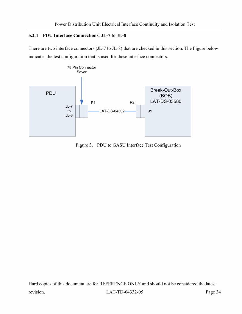
5.2.4 PDU Interface Connections, JL-7 to JL-8
There are two interface connectors (JL-7 to JL-8) that are checked in this section. The Figure below
indicates the test configuration that is used for these interface connectors.
JL-7to
JL-8
PDU
LAT-DS-04302
Break-Out-Box (BOB)
LAT-DS-03580
78 Pin Connector Saver
J1
P1 P2
Figure 3. PDU to GASU Interface Test Configuration
Power Distribution Unit Electrical Interface Continuity and Isolation Test
Hard copies of this document are for REFERENCE ONLY and should not be considered the latest
revision. LAT-TD-04332-05 Page 35
5.2.4.1 JL-7 Connector Checks
5.2.4.1.1 Continuity, PDU Side of Interface
This test ensures the connection of nodes on the interface under test. This is performed before
isolation tests to limit the number of those tests.
On the PDU side of the BOB, perform the continuity measurements (resistances are measured with a
digital multi-meter) as instructed by the data sheet:
1) Setup and connect the BOB and cables to the EUT by mating per the figure above, record per
the data sheet.
2) Set the multi-meter to read impedance (resistance). Set the range to auto-ranging. Measure and
record the resistances per the data sheet.
5.2.4.1.2 Power and Ground Isolation, PDU Side of Interface
On the PDU side of the BOB, perform the following isolation measurements (impedances are
measured with a digital multi-meter) as instructed by the data sheet:
1) Set the multi-meter to read impedance (resistance). Set the range to autoranging. Perform and
record the measurements per the data sheet.
2) Demate the BOB/BOC assembly from the connector saver in this test.

Power Distribution Unit Electrical Interface Continuity and Isolation Test
Hard copies of this document are for REFERENCE ONLY and should not be considered the latest
revision. LAT-TD-04332-05 Page 36
5.2.4.2 JL-8 Connector Checks
5.2.4.2.1 Continuity, PDU Side of Interface
This test ensures the connection of nodes on the interface under test. This is performed before
isolation tests to limit the number of those tests.
On the PDU side of the BOB, perform the continuity measurements (resistances are measured with a
digital multi-meter) as instructed by the data sheet:
1) Setup and connect the BOB and cables to the EUT by mating per the figure above, record per
the data sheet.
2) Set the multi-meter to read impedance (resistance). Set the range to auto-ranging. Measure
and record the resistances per the data sheet.
5.2.4.2.2 Power and Ground Isolation, PDU Side of Interface
On the PDU side of the BOB, perform the following isolation measurements (impedances are
measured with a digital multi-meter) as instructed by the data sheet:
1) Set the multi-meter to read impedance (resistance). Set the range to autoranging. Perform and
record the measurements per the data sheet.
2) Demate the BOB/BOC assembly from the connector saver in this test.

Power Distribution Unit Electrical Interface Continuity and Isolation Test
Hard copies of this document are for REFERENCE ONLY and should not be considered the latest
revision. LAT-TD-04332-05 Page 37
5.2.5 PDU Interface Connections, JL-9 to JL-11
There are three interface connectors (JL-9 to JL-11) that are checked in this section. The Figure
below indicates the test configuration that is used for these interface connectors.
JL-9to
JL-11
PDU
LAT-DS-04298
Break-Out-Box (BOB)
LAT-DS-03578
26 Pin Connector Saver
J1
P1 P2
Figure 4. PDU to EPU Interface Test Configuration

Power Distribution Unit Electrical Interface Continuity and Isolation Test
Hard copies of this document are for REFERENCE ONLY and should not be considered the latest
revision. LAT-TD-04332-05 Page 38
5.2.5.1 JL-9 Connector Checks
5.2.5.1.1 Continuity, PDU Side of Interface
This test ensures the connection of nodes on the interface under test. This is performed before
isolation tests to limit the number of those tests.
On the PDU side of the BOB, perform the continuity measurements (resistances are measured with a
digital multi-meter) as instructed by the data sheet:
1) Setup and connect the BOB and cables to the EUT by mating per the figure above, record per
the data sheet.
2) Set the multi-meter to read impedance (resistance). Set the range to auto-ranging. Measure
and record the resistances per the data sheet.
5.2.5.1.2 Power and Ground Isolation, PDU Side of Interface
On the PDU side of the BOB, perform the following isolation measurements (impedances are
measured with a digital multi-meter) as instructed by the data sheet:
1) Set the multi-meter to read impedance (resistance). Set the range to autoranging. Perform and
record the measurements per the data sheet.
2) Demate the BOB/BOC assembly from the connector saver in this test.
Power Distribution Unit Electrical Interface Continuity and Isolation Test
Hard copies of this document are for REFERENCE ONLY and should not be considered the latest
revision. LAT-TD-04332-05 Page 39
5.2.5.2 JL-10 Connector Checks
5.2.5.2.1 Continuity, PDU Side of Interface
This test ensures the connection of nodes on the interface under test. This is performed before
isolation tests to limit the number of those tests.
On the PDU side of the BOB, perform the continuity measurements (resistances are measured with a
digital multi-meter) as instructed by the data sheet:
1) Setup and connect the BOB and cables to the EUT by mating per the figure above, record per
the data sheet.
2) Set the multi-meter to read impedance (resistance). Set the range to auto-ranging. Measure
and record the resistances per the data sheet.
5.2.5.2.2 Power and Ground Isolation, PDU Side of Interface
On the PDU side of the BOB, perform the following isolation measurements (impedances are
measured with a digital multi-meter) as instructed by the data sheet:
1) Set the multi-meter to read impedance (resistance). Set the range to autoranging. Perform and
record the measurements per the data sheet.
2) Demate the BOB/BOC assembly from the connector saver in this test.

Power Distribution Unit Electrical Interface Continuity and Isolation Test
Hard copies of this document are for REFERENCE ONLY and should not be considered the latest
revision. LAT-TD-04332-05 Page 40
5.2.5.3 JL-11 Connector Checks
5.2.5.3.1 Continuity, PDU Side of Interface
This test ensures the connection of nodes on the interface under test. This is performed before
isolation tests to limit the number of those tests.
On the PDU side of the BOB, perform the continuity measurements (resistances are measured with a
digital multi-meter) as instructed by the data sheet:
1) Setup and connect the BOB and cables to the EUT by mating per the figure above, record per
the data sheet.
2) Set the multi-meter to read impedance (resistance). Set the range to auto-ranging. Measure
and record the resistances per the data sheet.
5.2.5.3.2 Power and Ground Isolation, PDU Side of Interface
On the PDU side of the BOB, perform the following isolation measurements (impedances are
measured with a digital multi-meter) as instructed by the data sheet:
1) Set the multi-meter to read impedance (resistance). Set the range to autoranging. Perform and
record the measurements per the data sheet.
2) Demate the BOB/BOC assembly from the connector saver in this test.

Power Distribution Unit Electrical Interface Continuity and Isolation Test
Hard copies of this document are for REFERENCE ONLY and should not be considered the latest
revision. LAT-TD-04332-05 Page 41
5.2.6 PDU Interface Connections, JL-13 to JL-28
There are sixteen interface connectors (JL-13 to JL-28) that are checked in this section. The Figure
below indicates the test configuration that is used for these interface connectors.
JL-13to
JL-28
PDU
LAT-DS-04298
Break-Out-Box (BOB)
LAT-DS-03578
26 Pin Connector Saver
J1
P1 P2
Figure 5. PDU to TPS Interface Test Configuration

Power Distribution Unit Electrical Interface Continuity and Isolation Test
Hard copies of this document are for REFERENCE ONLY and should not be considered the latest
revision. LAT-TD-04332-05 Page 42
5.2.6.1 JL-13 Connector Checks
5.2.6.1.1 Continuity, PDU Side of Interface
This test ensures the connection of nodes on the interface under test. This is performed before
isolation tests to limit the number of those tests.
On the PDU side of the BOB, perform the continuity measurements (resistances are measured with a
digital multi-meter) as instructed by the data sheet:
1) Setup and connect the BOB and cables to the EUT by mating per the figure above, record per
the data sheet.
2) Set the multi-meter to read impedance (resistance). Set the range to auto-ranging. Measure
and record the resistances per the data sheet.
5.2.6.1.2 Power and Ground Isolation, PDU Side of Interface
On the PDU side of the BOB, perform the following isolation measurements (impedances are
measured with a digital multi-meter) as instructed by the data sheet:
1) Set the multi-meter to read impedance (resistance). Set the range to autoranging. Perform and
record the measurements per the data sheet.
2) Demate the BOB/BOC assembly from the connector saver in this test.

Power Distribution Unit Electrical Interface Continuity and Isolation Test
Hard copies of this document are for REFERENCE ONLY and should not be considered the latest
revision. LAT-TD-04332-05 Page 43
5.2.6.2 JL-14 Connector Checks
5.2.6.2.1 Continuity, PDU Side of Interface
This test ensures the connection of nodes on the interface under test. This is performed before
isolation tests to limit the number of those tests.
On the PDU side of the BOB, perform the continuity measurements (resistances are measured with a
digital multi-meter) as instructed by the data sheet:
1) Setup and connect the BOB and cables to the EUT by mating per the figure above, record per
the data sheet.
2) Set the multi-meter to read impedance (resistance). Set the range to auto-ranging. Measure
and record the resistances per the data sheet.
5.2.6.2.2 Power and Ground Isolation, PDU Side of Interface
On the PDU side of the BOB, perform the following isolation measurements (impedances are
measured with a digital multi-meter) as instructed by the data sheet:
1) Set the multi-meter to read impedance (resistance). Set the range to autoranging. Perform and
record the measurements per the data sheet.
2) Demate the BOB/BOC assembly from the connector saver in this test.

Power Distribution Unit Electrical Interface Continuity and Isolation Test
Hard copies of this document are for REFERENCE ONLY and should not be considered the latest
revision. LAT-TD-04332-05 Page 44
5.2.6.3 JL-15 Connector Checks
5.2.6.3.1 Continuity, PDU Side of Interface
This test ensures the connection of nodes on the interface under test. This is performed before
isolation tests to limit the number of those tests.
On the PDU side of the BOB, perform the continuity measurements (resistances are measured with a
digital multi-meter) as instructed by the data sheet:
1) Setup and connect the BOB and cables to the EUT by mating per the figure above, record per
the data sheet.
2) Set the multi-meter to read impedance (resistance). Set the range to auto-ranging. Measure
and record the resistances per the data sheet.
5.2.6.3.2 Power and Ground Isolation, PDU Side of Interface
On the PDU side of the BOB, perform the following isolation measurements (impedances are
measured with a digital multi-meter) as instructed by the data sheet:
1) Set the multi-meter to read impedance (resistance). Set the range to autoranging. Perform and
record the measurements per the data sheet.
2) Demate the BOB/BOC assembly from the connector saver in this test.

Power Distribution Unit Electrical Interface Continuity and Isolation Test
Hard copies of this document are for REFERENCE ONLY and should not be considered the latest
revision. LAT-TD-04332-05 Page 45
5.2.6.4 JL-16 Connector Checks
5.2.6.4.1 Continuity, PDU Side of Interface
This test ensures the connection of nodes on the interface under test. This is performed before
isolation tests to limit the number of those tests.
On the PDU side of the BOB, perform the continuity measurements (resistances are measured with a
digital multi-meter) as instructed by the data sheet:
1) Setup and connect the BOB and cables to the EUT by mating per the figure above, record per
the data sheet.
2) Set the multi-meter to read impedance (resistance). Set the range to auto-ranging. Measure
and record the resistances per the data sheet.
5.2.6.4.2 Power and Ground Isolation, PDU Side of Interface
On the PDU side of the BOB, perform the following isolation measurements (impedances are
measured with a digital multi-meter) as instructed by the data sheet:
1) Set the multi-meter to read impedance (resistance). Set the range to autoranging. Perform and
record the measurements per the data sheet.
2) Demate the BOB/BOC assembly from the connector saver in this test.

Power Distribution Unit Electrical Interface Continuity and Isolation Test
Hard copies of this document are for REFERENCE ONLY and should not be considered the latest
revision. LAT-TD-04332-05 Page 46
5.2.6.5 JL-17 Connector Checks
5.2.6.5.1 Continuity, PDU Side of Interface
This test ensures the connection of nodes on the interface under test. This is performed before
isolation tests to limit the number of those tests.
On the PDU side of the BOB, perform the continuity measurements (resistances are measured with a
digital multi-meter) as instructed by the data sheet:
1) Setup and connect the BOB and cables to the EUT by mating per the figure above, record per
the data sheet.
2) Set the multi-meter to read impedance (resistance). Set the range to auto-ranging. Measure
and record the resistances per the data sheet.
5.2.6.5.2 Power and Ground Isolation, PDU Side of Interface
On the PDU side of the BOB, perform the following isolation measurements (impedances are
measured with a digital multi-meter) as instructed by the data sheet:
1) Set the multi-meter to read impedance (resistance). Set the range to autoranging. Perform and
record the measurements per the data sheet.
2) Demate the BOB/BOC assembly from the connector saver in this test.

Power Distribution Unit Electrical Interface Continuity and Isolation Test
Hard copies of this document are for REFERENCE ONLY and should not be considered the latest
revision. LAT-TD-04332-05 Page 47
5.2.6.6 JL-18 Connector Checks
5.2.6.6.1 Continuity, PDU Side of Interface
This test ensures the connection of nodes on the interface under test. This is performed before
isolation tests to limit the number of those tests.
On the PDU side of the BOB, perform the continuity measurements (resistances are measured with a
digital multi-meter) as instructed by the data sheet:
1) Setup and connect the BOB and cables to the EUT by mating per the figure above, record per
the data sheet.
2) Set the multi-meter to read impedance (resistance). Set the range to auto-ranging. Measure
and record the resistances per the data sheet.
5.2.6.6.2 Power and Ground Isolation, PDU Side of Interface
On the PDU side of the BOB, perform the following isolation measurements (impedances are
measured with a digital multi-meter) as instructed by the data sheet:
1) Set the multi-meter to read impedance (resistance). Set the range to autoranging. Perform and
record the measurements per the data sheet.
2) Demate the BOB/BOC assembly from the connector saver in this test.

Power Distribution Unit Electrical Interface Continuity and Isolation Test
Hard copies of this document are for REFERENCE ONLY and should not be considered the latest
revision. LAT-TD-04332-05 Page 48
5.2.6.7 JL-19 Connector Checks
5.2.6.7.1 Continuity, PDU Side of Interface
This test ensures the connection of nodes on the interface under test. This is performed before
isolation tests to limit the number of those tests.
On the PDU side of the BOB, perform the continuity measurements (resistances are measured with a
digital multi-meter) as instructed by the data sheet:
1) Setup and connect the BOB and cables to the EUT by mating per the figure above, record per
the data sheet.
2) Set the multi-meter to read impedance (resistance). Set the range to auto-ranging. Measure
and record the resistances per the data sheet.
5.2.6.7.2 Power and Ground Isolation, PDU Side of Interface
On the PDU side of the BOB, perform the following isolation measurements (impedances are
measured with a digital multi-meter) as instructed by the data sheet:
1) Set the multi-meter to read impedance (resistance). Set the range to autoranging. Perform and
record the measurements per the data sheet.
2) Demate the BOB/BOC assembly from the connector saver in this test.
Power Distribution Unit Electrical Interface Continuity and Isolation Test
Hard copies of this document are for REFERENCE ONLY and should not be considered the latest
revision. LAT-TD-04332-05 Page 49
5.2.6.8 JL-20 Connector Checks
5.2.6.8.1 Continuity, PDU Side of Interface
This test ensures the connection of nodes on the interface under test. This is performed before
isolation tests to limit the number of those tests.
On the PDU side of the BOB, perform the continuity measurements (resistances are measured with a
digital multi-meter) as instructed by the data sheet:
1) Setup and connect the BOB and cables to the EUT by mating per the figure above, record per
the data sheet.
2) Set the multi-meter to read impedance (resistance). Set the range to auto-ranging. Measure
and record the resistances per the data sheet.
5.2.6.8.2 Power and Ground Isolation, PDU Side of Interface
On the PDU side of the BOB, perform the following isolation measurements (impedances are
measured with a digital multi-meter) as instructed by the data sheet:
1) Set the multi-meter to read impedance (resistance). Set the range to autoranging. Perform and
record the measurements per the data sheet.
2) Demate the BOB/BOC assembly from the connector saver in this test.

Power Distribution Unit Electrical Interface Continuity and Isolation Test
Hard copies of this document are for REFERENCE ONLY and should not be considered the latest
revision. LAT-TD-04332-05 Page 50
5.2.6.9 JL-21 Connector Checks
5.2.6.9.1 Continuity, PDU Side of Interface
This test ensures the connection of nodes on the interface under test. This is performed before
isolation tests to limit the number of those tests.
On the PDU side of the BOB, perform the continuity measurements (resistances are measured with a
digital multi-meter) as instructed by the data sheet:
1) Setup and connect the BOB and cables to the EUT by mating per the figure above, record per
the data sheet.
2) Set the multi-meter to read impedance (resistance). Set the range to auto-ranging. Measure
and record the resistances per the data sheet.
5.2.6.9.2 Power and Ground Isolation, PDU Side of Interface
On the PDU side of the BOB, perform the following isolation measurements (impedances are
measured with a digital multi-meter) as instructed by the data sheet:
1) Set the multi-meter to read impedance (resistance). Set the range to autoranging. Perform and
record the measurements per the data sheet.
2) Demate the BOB/BOC assembly from the connector saver in this test.

Power Distribution Unit Electrical Interface Continuity and Isolation Test
Hard copies of this document are for REFERENCE ONLY and should not be considered the latest
revision. LAT-TD-04332-05 Page 51
5.2.6.10 JL-22 Connector Checks
5.2.6.10.1 Continuity, PDU Side of Interface
This test ensures the connection of nodes on the interface under test. This is performed before
isolation tests to limit the number of those tests.
On the PDU side of the BOB, perform the continuity measurements (resistances are measured with a
digital multi-meter) as instructed by the data sheet:
1) Setup and connect the BOB and cables to the EUT by mating per the figure above, record per
the data sheet.
2) Set the multi-meter to read impedance (resistance). Set the range to auto-ranging. Measure
and record the resistances per the data sheet.
5.2.6.10.2 Power and Ground Isolation, PDU Side of Interface
On the PDU side of the BOB, perform the following isolation measurements (impedances are
measured with a digital multi-meter) as instructed by the data sheet:
1) Set the multi-meter to read impedance (resistance). Set the range to autoranging. Perform and
record the measurements per the data sheet.
2) Demate the BOB/BOC assembly from the connector saver in this test.

Power Distribution Unit Electrical Interface Continuity and Isolation Test
Hard copies of this document are for REFERENCE ONLY and should not be considered the latest
revision. LAT-TD-04332-05 Page 52
5.2.6.11 JL-23 Connector Checks
5.2.6.11.1 Continuity, PDU Side of Interface
This test ensures the connection of nodes on the interface under test. This is performed before
isolation tests to limit the number of those tests.
On the PDU side of the BOB, perform the continuity measurements (resistances are measured with a
digital multi-meter) as instructed by the data sheet:
1) Setup and connect the BOB and cables to the EUT by mating per the figure above, record per
the data sheet.
2) Set the multi-meter to read impedance (resistance). Set the range to auto-ranging. Measure
and record the resistances per the data sheet.
5.2.6.11.2 Power and Ground Isolation, PDU Side of Interface
On the PDU side of the BOB, perform the following isolation measurements (impedances are
measured with a digital multi-meter) as instructed by the data sheet:
1) Set the multi-meter to read impedance (resistance). Set the range to autoranging. Perform and
record the measurements per the data sheet.
2) Demate the BOB/BOC assembly from the connector saver in this test.

Power Distribution Unit Electrical Interface Continuity and Isolation Test
Hard copies of this document are for REFERENCE ONLY and should not be considered the latest
revision. LAT-TD-04332-05 Page 53
5.2.6.12 JL-24 Connector Checks
5.2.6.12.1 Continuity, PDU Side of Interface
This test ensures the connection of nodes on the interface under test. This is performed before
isolation tests to limit the number of those tests.
On the PDU side of the BOB, perform the continuity measurements (resistances are measured with a
digital multi-meter) as instructed by the data sheet:
1) Setup and connect the BOB and cables to the EUT by mating per the figure above, record per
the data sheet.
2) Set the multi-meter to read impedance (resistance). Set the range to auto-ranging. Measure
and record the resistances per the data sheet.
5.2.6.12.2 Power and Ground Isolation, PDU Side of Interface
On the PDU side of the BOB, perform the following isolation measurements (impedances are
measured with a digital multi-meter) as instructed by the data sheet:
1) Set the multi-meter to read impedance (resistance). Set the range to autoranging. Perform and
record the measurements per the data sheet.
2) Demate the BOB/BOC assembly from the connector saver in this test.
Power Distribution Unit Electrical Interface Continuity and Isolation Test
Hard copies of this document are for REFERENCE ONLY and should not be considered the latest
revision. LAT-TD-04332-05 Page 54
5.2.6.13 JL-25 Connector Checks
5.2.6.13.1 Continuity, PDU Side of Interface
This test ensures the connection of nodes on the interface under test. This is performed before
isolation tests to limit the number of those tests.
On the PDU side of the BOB, perform the continuity measurements (resistances are measured with a
digital multi-meter) as instructed by the data sheet:
1) Setup and connect the BOB and cables to the EUT by mating per the figure above, record per
the data sheet.
2) Set the multi-meter to read impedance (resistance). Set the range to auto-ranging. Measure
and record the resistances per the data sheet.
5.2.6.13.2 Power and Ground Isolation, PDU Side of Interface
On the PDU side of the BOB, perform the following isolation measurements (impedances are
measured with a digital multi-meter) as instructed by the data sheet:
1) Set the multi-meter to read impedance (resistance). Set the range to autoranging. Perform and
record the measurements per the data sheet.
2) Demate the BOB/BOC assembly from the connector saver in this test.

Power Distribution Unit Electrical Interface Continuity and Isolation Test
Hard copies of this document are for REFERENCE ONLY and should not be considered the latest
revision. LAT-TD-04332-05 Page 55
5.2.6.14 JL-26 Connector Checks
5.2.6.14.1 Continuity, PDU Side of Interface
This test ensures the connection of nodes on the interface under test. This is performed before
isolation tests to limit the number of those tests.
On the PDU side of the BOB, perform the continuity measurements (resistances are measured with a
digital multi-meter) as instructed by the data sheet:
1) Setup and connect the BOB and cables to the EUT by mating per the figure above, record per
the data sheet.
2) Set the multi-meter to read impedance (resistance). Set the range to auto-ranging. Measure
and record the resistances per the data sheet.
5.2.6.14.2 Power and Ground Isolation, PDU Side of Interface
On the PDU side of the BOB, perform the following isolation measurements (impedances are
measured with a digital multi-meter) as instructed by the data sheet:
1) Set the multi-meter to read impedance (resistance). Set the range to autoranging. Perform and
record the measurements per the data sheet.
2) Demate the BOB/BOC assembly from the connector saver in this test.

Power Distribution Unit Electrical Interface Continuity and Isolation Test
Hard copies of this document are for REFERENCE ONLY and should not be considered the latest
revision. LAT-TD-04332-05 Page 56
5.2.6.15 JL-27 Connector Checks
5.2.6.15.1 Continuity, PDU Side of Interface
This test ensures the connection of nodes on the interface under test. This is performed before
isolation tests to limit the number of those tests.
On the PDU side of the BOB, perform the continuity measurements (resistances are measured with a
digital multi-meter) as instructed by the data sheet:
1) Setup and connect the BOB and cables to the EUT by mating per the figure above, record per
the data sheet.
2) Set the multi-meter to read impedance (resistance). Set the range to auto-ranging. Measure
and record the resistances per the data sheet.
5.2.6.15.2 Power and Ground Isolation, PDU Side of Interface
On the PDU side of the BOB, perform the following isolation measurements (impedances are
measured with a digital multi-meter) as instructed by the data sheet:
1) Set the multi-meter to read impedance (resistance). Set the range to autoranging. Perform and
record the measurements per the data sheet.
2) Demate the BOB/BOC assembly from the connector saver in this test.

Power Distribution Unit Electrical Interface Continuity and Isolation Test
Hard copies of this document are for REFERENCE ONLY and should not be considered the latest
revision. LAT-TD-04332-05 Page 57
5.2.6.16 JL-28 Connector Checks
5.2.6.16.1 Continuity, PDU Side of Interface
This test ensures the connection of nodes on the interface under test. This is performed before
isolation tests to limit the number of those tests.
On the PDU side of the BOB, perform the continuity measurements (resistances are measured with a
digital multi-meter) as instructed by the data sheet:
1) Setup and connect the BOB and cables to the EUT by mating per the figure above, record per
the data sheet.
2) Set the multi-meter to read impedance (resistance). Set the range to auto-ranging. Measure
and record the resistances per the data sheet.
5.2.6.16.2 Power and Ground Isolation, PDU Side of Interface
On the PDU side of the BOB, perform the following isolation measurements (impedances are
measured with a digital multi-meter) as instructed by the data sheet:
1) Set the multi-meter to read impedance (resistance). Set the range to autoranging. Perform and
record the measurements per the data sheet.
2) Demate the BOB/BOC assembly from the connector saver in this test.

Power Distribution Unit Electrical Interface Continuity and Isolation Test
Hard copies of this document are for REFERENCE ONLY and should not be considered the latest
revision. LAT-TD-04332-05 Page 58
5.2.7 PDU Interface Interconnections, JL-3/JL-4 to JL-7 and JL-8
There are two interface connectors JL-3/JL-4 that are checked in this section to JL-7 and JL-8. The
Figure below indicates the test configuration that is used for these interface connectors.
JL-7 LAT-DS-04302
Break-Out-Box (BOB)
LAT-DS-03580
78 Pin Connector Saver
J1
P1 P2
JL-3to
JL-4
PDU
LAT-DS-04289
Break-Out-Box (BOB)
LAT-DS-03580
66 Pin Connector Saver
J2
P1 P2
JL-8 LAT-DS-04302
Break-Out-Box (BOB)
LAT-DS-03580
78 Pin Connector Saver
J1
P1 P2
Figure 6. PDU Interface Interconnections Test Configuration

Power Distribution Unit Electrical Interface Continuity and Isolation Test
Hard copies of this document are for REFERENCE ONLY and should not be considered the latest
revision. LAT-TD-04332-05 Page 59
5.2.7.1 JL-3 to JL-7 and JL-8 Connector Checks, Continuity, PDU Side of Interface
This test ensures the connection of nodes on the interface under test. This is performed before
isolation tests to limit the number of those tests. To reduce the number of BOBs/BOCs required, this
test is performed in two mating/demating steps.
On the PDU side of the BOB, perform the continuity measurements (resistances are measured with a
digital multi-meter) as instructed by the data sheet:
1) Setup and connect the BOB and cables to the EUT by mating per the figure above, the
BOBs/BOCs connected to JL3 and JL7, record per the data sheet.
2) Set the multi-meter to read impedance (resistance). Set the range to auto-ranging. Measure
and record the resistances per the data sheet.
3) Demate the BOB/BOC connected to the JL7 connector saver and mate it with the JL8
connector saver. Record per the data sheet.
4) Measure and record the resistances per the data sheet.
5) Demate test setup from JL3 and JL8 connector savers.

Power Distribution Unit Electrical Interface Continuity and Isolation Test
Hard copies of this document are for REFERENCE ONLY and should not be considered the latest
revision. LAT-TD-04332-05 Page 60
5.2.7.2 JL-4 to JL-7 and JL-8 Connector Checks, Continuity, PDU Side of Interface
This test ensures the connection of nodes on the interface under test. This is performed before
isolation tests to limit the number of those tests. To reduce the number of BOBs/BOCs required, this
test is performed in two mating/demating steps.
On the PDU side of the BOB, perform the continuity measurements (resistances are measured with a
digital multi-meter) as instructed by the data sheet:
1) Setup and connect the BOB and cables to the EUT by mating per the figure above the
BOBs/BOCs connected to JL4 and JL7, record per the data sheet.
2) Set the multi-meter to read impedance (resistance). Set the range to auto-ranging. Measure
and record the resistances per the data sheet.
3) Demate the BOB/BOC connected to the JL7 connector saver and mate it with the JL8
connector saver. Record per the data sheet.
4) Measure and record the resistances per the data sheet.
5) Demate test setup from JL4 and JL8 connector savers.
Power Distribution Unit Electrical Interface Continuity and Isolation Test
Hard copies of this document are for REFERENCE ONLY and should not be considered the latest
revision. LAT-TD-04332-05 Page 61
5.3 Signal Isolation and Controlled Resistance Testing (Manual)
This section provides the manual testing methods for the PDU unit. The EICIT checks are directed
by using a LAT AIDS document which directs the operator to the various documents to complete
testing.
The two types of tests that are performed in this section are:
• Signal Isolation from Power and Ground
• Controlled Resistance
5.3.1 Pre-Operation Verifications
This section details the pre-operation verification checks before testing the EUT.
To perform the pre-operation verification checks:
CAUTION: Follow ESD processes during this checkout.
Note: Prior to the connection of any hardware to other electronics, it shall be verified that
all power supplies, signal generators, VME racks, and any other test and
measurement equipment shall be connected to the same AC ground. The simplest
way to do this is to connect all AC-powered equipment to the same power strip. In
cases where this is not practical (e.g. possibly a thermal-vacuum test), greater care
must be taken to ensure there are no floating grounds since this would represent a
hazard to the electronics.
Note: Leave all connector savers in place until the actual flight mate is to be made. The
AIDS provides authorization to install and remove connector savers.
Note: All flight mates and demates must be completed and entered into the mate demate log
before measurements are made or testing can start.

Power Distribution Unit Electrical Interface Continuity and Isolation Test
Hard copies of this document are for REFERENCE ONLY and should not be considered the latest
revision. LAT-TD-04332-05 Page 62
1) Notify QAE that testing is expected to start, so the QAE can arrange to be present for the
setup and start of testing. Record per the data sheet.
2) Verify that the Test Readiness Review has concluded and all parties have signed the cover
sheet. Record per the data sheet.
3) Record the serial numbers and locations per the data sheet.
4) Turn off the power on the LAT, or the EGSE. Record in the data sheet.
5) Set the DMM to the auto-ranging setting. Record in the data sheet.
6) Measure DMM lead resistance by connecting the two leads together. Record in the data
sheet.
7) Tie the BOB chassis to technical ground. Measure the resistance between the BOB chassis
and technical ground. Record in the data sheet.
8) Remove all shorting plugs from the BOB. Record in the data sheet.
9) Measure the resistance between the EUT chassis and technical ground. Record in the data
sheet.
10) Verify connector savers are on all flight hardware (install the connector savers per
authorization from an AIDS if necessary). Record in the data sheet.
11) Verify that the test equipment and participant list have been completed.

Power Distribution Unit Electrical Interface Continuity and Isolation Test
Hard copies of this document are for REFERENCE ONLY and should not be considered the latest
revision. LAT-TD-04332-05 Page 63
5.3.2 PDU Interface Connections, JL-3 to JL-4
There are two interface connectors (JL-3 to JL-4) that are checked in this section. The Figure below
indicates the test configuration that is used for these interface connectors.
JL-3to
JL-4
PDU
LAT-DS-04289
Break-Out-Box (BOB)
LAT-DS-03580
66 Pin Connector Saver
J2
P1 P2
Figure 7. PDU to S/C Interface Test Configuration

Power Distribution Unit Electrical Interface Continuity and Isolation Test
Hard copies of this document are for REFERENCE ONLY and should not be considered the latest
revision. LAT-TD-04332-05 Page 64
5.3.2.1 JL-3 Connector Checks
This section checks the interface connector JL-3.
5.3.2.1.1 Signal Isolation from Power and Ground
This test verifies the isolation of nodes and signal lines on the interface under test.
Note: Continuity, power and ground isolation checks must be performed prior to this step.
On the PDU side of the BOB, perform the following signal isolation measurements (resistances are
measured with a digital multi-meter) as instructed by the data sheet:
1) Setup and connect the BOB and cables to the EUT by mating per the figure above, record per
the data sheet.

Power Distribution Unit Electrical Interface Continuity and Isolation Test
Hard copies of this document are for REFERENCE ONLY and should not be considered the latest
revision. LAT-TD-04332-05 Page 65
2) Setup the black test leads (Pomona) as a common connection, see the Figure below.
1
64
BOBBOB Test
Points
Black Test Leads
(jumpered together) Red Test
Lead
DMM
Figure 8. JL-3 – JL-4 Common Test Lead Connection
3) Set the multi-meter to read resistance. Set the range to autoranging. Perform and record the
measurements per the data sheet.
Note: Make sure that the setup for the common test leads remains connected for all
measurements in this step.
5.3.2.1.2 Controlled Resistances
This test verifies the expected resistance between line pairs on the interface under test.
On the PDU side of the BOB, perform the following resistance measurements (resistances are
measured with a digital multi-meter) as instructed by the data sheet:
1) Set the multi-meter to read resistance. Set the range to autoranging. Perform and record the
measurements per the data sheet.
2) Demate the BOB/BOC assembly from the connector saver in this test.
Power Distribution Unit Electrical Interface Continuity and Isolation Test
Hard copies of this document are for REFERENCE ONLY and should not be considered the latest
revision. LAT-TD-04332-05 Page 66
5.3.2.2 JL-4 Connector Checks
This section checks the interface connector JL-4.
5.3.2.2.1 Signal Isolation from Power and Ground
This test verifies the isolation of nodes and signal lines on the interface under test.
Note: Continuity, power and ground isolation checks must be performed prior to this step.
On the PDU side of the BOB, perform the following signal isolation measurements (resistances are
measured with a digital multi-meter) as instructed by the data sheet:
1) Setup and connect the BOB and cables to the EUT by mating per the figure above, record per
the data sheet.
2) Setup the black test leads (Pomona) as a common connection, see the common test lead
Figure above.
3) Set the multi-meter to read resistance. Set the range to autoranging. Perform and record the
measurements per the data sheet.
Note: Make sure that the setup for the common test leads remains connected for all
measurements in this step.

Power Distribution Unit Electrical Interface Continuity and Isolation Test
Hard copies of this document are for REFERENCE ONLY and should not be considered the latest
revision. LAT-TD-04332-05 Page 67
5.3.2.2.2 Controlled Resistances
This test verifies the expected resistance between line pairs on the interface under test.
On the PDU side of the BOB, perform the following resistance measurements (resistances are
measured with a digital multi-meter) as instructed by the data sheet:
1) Set the multi-meter to read resistance. Set the range to autoranging. Perform and record the
measurements per the data sheet.
2) Demate the BOB/BOC assembly from the connector saver in this test.

Power Distribution Unit Electrical Interface Continuity and Isolation Test
Hard copies of this document are for REFERENCE ONLY and should not be considered the latest
revision. LAT-TD-04332-05 Page 68
5.3.3 PDU Interface Connections, JL-5 to JL-6
There are two interface connectors (JL-5 to JL-6) that are checked in this section. Only Signal
Isolation from Power and Ground checks are performed for this connector. The Figure below
indicates the test configuration that is used for these interface connectors.
JL-5to
JL-6
PDU
LAT-DS-04301
Break-Out-Box (BOB)
LAT-DS-03579
44 Pin Connector Saver
J2
P1 P2
Figure 9. PDU to SIU (Primary and Redundant) Interface Test Configuration

Power Distribution Unit Electrical Interface Continuity and Isolation Test
Hard copies of this document are for REFERENCE ONLY and should not be considered the latest
revision. LAT-TD-04332-05 Page 69
5.3.3.1 JL-5 Connector Checks
This section checks the interface connector JL-5.
5.3.3.1.1 Signal Isolation from Power and Ground
This test verifies the isolation of nodes and signal lines on the interface under test.
Note: Continuity, power and ground isolation checks must be performed prior to this step.
On the PDU side of the BOB, perform the following signal isolation measurements (resistances are
measured with a digital multi-meter) as instructed by the data sheet:
1) Setup and connect the BOB and cables to the EUT by mating per the figure above, record per
the data sheet.
2) Set the multi-meter to read resistance. Set the range to autoranging. Perform and record the
measurements per the data sheet.
3) Demate the BOB/BOC assembly from the connector saver in this test.
Power Distribution Unit Electrical Interface Continuity and Isolation Test
Hard copies of this document are for REFERENCE ONLY and should not be considered the latest
revision. LAT-TD-04332-05 Page 70
5.3.3.2 JL-6 Connector Checks
This section checks the interface connector JL-6.
5.3.3.2.1 Signal Isolation from Power and Ground
This test verifies the isolation of nodes and signal lines on the interface under test.
Note: Continuity, power and ground isolation checks must be performed prior to this step.
On the PDU side of the BOB, perform the following signal isolation measurements (resistances are
measured with a digital multi-meter) as instructed by the data sheet:
1) Setup and connect the BOB and cables to the EUT by mating per the figure above, record per
the data sheet.
2) Set the multi-meter to read resistance. Set the range to autoranging. Perform and record the
measurements per the data sheet.
3) Demate the BOB/BOC assembly from the connector saver in this test.

Power Distribution Unit Electrical Interface Continuity and Isolation Test
Hard copies of this document are for REFERENCE ONLY and should not be considered the latest
revision. LAT-TD-04332-05 Page 71
5.3.4 PDU Interface Connections, JL-7 to JL-8
There are two interface connectors (JL-7 to JL-8) that are checked in this section. The Figure below
indicates the test configuration that is used for these interface connectors.
JL-7to
JL-8
PDU
LAT-DS-04302
Break-Out-Box (BOB)
LAT-DS-03580
78 Pin Connector Saver
J1
P1 P2
Figure 10. PDU to GASU Interface Test Configuration
5.3.4.1 JL-7 Connector Checks
This section checks the interface connector JL-7.
5.3.4.1.1 Signal Isolation from Power and Ground
This test verifies the isolation of nodes and signal lines on the interface under test.
Note: Continuity, power and ground isolation checks must be performed prior to this step.
On the PDU side of the BOB, perform the following signal isolation measurements (resistances are
measured with a digital multi-meter) as instructed by the data sheet:
1) Setup and connect the BOB and cables to the EUT by mating per the figure above, record per
the data sheet.

Power Distribution Unit Electrical Interface Continuity and Isolation Test
Hard copies of this document are for REFERENCE ONLY and should not be considered the latest
revision. LAT-TD-04332-05 Page 72
2) Setup the black test leads (Pomona) as a common connection, see the Figure below. Record
per the data sheet.
1
2
21
40
60
BOBBOB Test
Points
Black Test Leads
(jumpered together) Red Test
Lead
DMM
Figure 11. JL-7 – JL-8 Common Test Lead Connection
3) Set the multi-meter to read resistance. Set the range to autoranging. Perform and record the
measurements per the data sheet.
Note: Make sure that the setup for the common test leads remains connected for all
measurements in this step.
5.3.4.1.2 Controlled Resistances
This test verifies the expected resistance between line pairs on the interface under test.
On the PDU side of the BOB, perform the following resistance measurements (resistances are
measured with a digital multi-meter) as instructed by the data sheet:
1) Set the multi-meter to read resistance. Set the range to autoranging. Perform and record the
measurements per the data sheet.
2) Demate the BOB/BOC assembly from the connector saver in this test.

Power Distribution Unit Electrical Interface Continuity and Isolation Test
Hard copies of this document are for REFERENCE ONLY and should not be considered the latest
revision. LAT-TD-04332-05 Page 73
5.3.4.2 JL-8 Connector Checks
This section checks the interface connector JL-8.
5.3.4.2.1 Signal Isolation from Power and Ground
This test verifies the isolation of nodes and signal lines on the interface under test.
Note: Continuity, power and ground isolation checks must be performed prior to this step.
On the PDU side of the BOB, perform the following signal isolation measurements (resistances are
measured with a digital multi-meter) as instructed by the data sheet:
1) Setup and connect the BOB and cables to the EUT by mating per the figure above, record per
the data sheet.
2) Setup the black test leads (Pomona) as a common connection, see the common test lead
Figure above.
3) Set the multi-meter to read resistance. Set the range to autoranging. Perform and record the
measurements per the data sheet.
Note: Make sure that the setup for the common test leads remains connected for all
measurements in this step.

Power Distribution Unit Electrical Interface Continuity and Isolation Test
Hard copies of this document are for REFERENCE ONLY and should not be considered the latest
revision. LAT-TD-04332-05 Page 74
5.3.4.2.2 Controlled Resistances
This test verifies the expected resistance between line pairs on the interface under test.
On the PDU side of the BOB, perform the following resistance measurements (resistances are
measured with a digital multi-meter) as instructed by the data sheet:
1) Set the multi-meter to read resistance. Set the range to autoranging. Perform and record the
measurements per the data sheet.
2) Demate the BOB/BOC assembly from the connector saver in this test.

Power Distribution Unit Electrical Interface Continuity and Isolation Test
Hard copies of this document are for REFERENCE ONLY and should not be considered the latest
revision. LAT-TD-04332-05 Page 75
5.3.5 PDU Interface Connections, JL-9 to JL-11
There are three interface connectors (JL-9 to JL-11) that are checked in this section. The Figure
below indicates the test configuration that is used for these interface connectors.
JL-9to
JL-11
PDU
LAT-DS-04298
Break-Out-Box (BOB)
LAT-DS-03578
26 Pin Connector Saver
J1
P1 P2
Figure 12. PDU to EPU (1-3) Interface Test Configuration

Power Distribution Unit Electrical Interface Continuity and Isolation Test
Hard copies of this document are for REFERENCE ONLY and should not be considered the latest
revision. LAT-TD-04332-05 Page 76
5.3.5.1 JL-9 Connector Checks
This section checks the interface connector JL-9.
5.3.5.1.1 Signal Isolation from Power and Ground
This test verifies the isolation of nodes and signal lines on the interface under test.
Note: Continuity, power and ground isolation checks must be performed prior to this step.
On the PDU side of the BOB, perform the following signal isolation measurements (resistances are
measured with a digital multi-meter) as instructed by the data sheet:
1) Setup and connect the BOB and cables to the EUT by mating per the figure above, record per
the data sheet.
2) Setup the black test leads (Pomona) as a common connection, see the Figure below. Record
per the data sheet.
1
3
5
BOBBOB Test
Points
Black Test Leads
(jumpered together) Red Test
Lead
DMM
Figure 13. JL-9 – JL-11 Common Test Lead Connection
3) Set the multi-meter to read resistance. Set the range to autoranging. Perform and record the
measurements per the data sheet.
Note: Make sure that the setup for the common test leads remains connected for all
measurements in this step.

Power Distribution Unit Electrical Interface Continuity and Isolation Test
Hard copies of this document are for REFERENCE ONLY and should not be considered the latest
revision. LAT-TD-04332-05 Page 77
5.3.5.2 JL-10 Connector Checks
This section checks the interface connector JL-10.
5.3.5.2.1 Signal Isolation from Power and Ground
This test verifies the isolation of nodes and signal lines on the interface under test.
Note: Continuity, power and ground isolation checks must be performed prior to this step.
On the PDU side of the BOB, perform the following signal isolation measurements (resistances are
measured with a digital multi-meter) as instructed by the data sheet:
1) Setup and connect the BOB and cables to the EUT by mating per the figure above, record per
the data sheet.
2) Setup the black test leads (Pomona) as a common connection, see the common test lead
Figure above. Record per the data sheet.
3) Set the multi-meter to read resistance. Set the range to autoranging. Perform and record the
measurements per the data sheet.
Note: Make sure that the setup for the common test leads remains connected for all
measurements in this step.

Power Distribution Unit Electrical Interface Continuity and Isolation Test
Hard copies of this document are for REFERENCE ONLY and should not be considered the latest
revision. LAT-TD-04332-05 Page 78
5.3.5.3 JL-11 Connector Checks
This section checks the interface connector JL-11.
5.3.5.3.1 Signal Isolation from Power and Ground
This test verifies the isolation of nodes and signal lines on the interface under test.
Note: Continuity, power and ground isolation checks must be performed prior to this step.
On the PDU side of the BOB, perform the following signal isolation measurements (resistances are
measured with a digital multi-meter) as instructed by the data sheet:
1) Setup and connect the BOB and cables to the EUT by mating per the figure above, record per
the data sheet.
2) Setup the black test leads (Pomona) as a common connection, see the common test lead
Figure above. Record per the data sheet.
3) Set the multi-meter to read resistance. Set the range to autoranging. Perform and record the
measurements per the data sheet.
Note: Make sure that the setup for the common test leads remains connected for all
measurements in this step.
4) Demate the BOB/BOC assembly from the connector saver in this test.

Power Distribution Unit Electrical Interface Continuity and Isolation Test
Hard copies of this document are for REFERENCE ONLY and should not be considered the latest
revision. LAT-TD-04332-05 Page 79
5.3.6 PDU Interface Connections, JL-13 to JL-28
There are sixteen interface connectors (JL-13 to JL-28) that are checked in this section. The Figure
below indicates the test configuration that is used for these interface connectors.
JL-13to
JL-28
PDU
LAT-DS-04298
Break-Out-Box (BOB)
LAT-DS-03578
26 Pin Connector Saver
J1
P1 P2
Figure 14. PDU to TPS Interface Test Configuration

Power Distribution Unit Electrical Interface Continuity and Isolation Test
Hard copies of this document are for REFERENCE ONLY and should not be considered the latest
revision. LAT-TD-04332-05 Page 80
5.3.6.1 JL-13 Connector Checks
This section checks the interface connector JL-13.
5.3.6.1.1 Signal Isolation from Power and Ground
This test verifies the isolation of nodes and signal lines on the interface under test.
Note: Continuity, power and ground isolation checks must be performed prior to this step.
On the PDU side of the BOB, perform the following signal isolation measurements (resistances are
measured with a digital multi-meter) as instructed by the data sheet:
1) Setup and connect the BOB and cables to the EUT by mating per the figure above, record per
the data sheet.
2) Setup the black test leads (Pomona) as a common connection, see the Figure below. Record
per the data sheet.
1
3
5
BOBBOB Test
Points
Black Test Leads
(jumpered together) Red Test
Lead
DMM
Figure 15. JL-13 – JL-28 Common Test Lead Connection
3) Set the multi-meter to read resistance. Set the range to autoranging. Perform and record the
measurements per the data sheet.
Note: Make sure that the setup for the common test leads remains connected for all
measurements in this step.

Power Distribution Unit Electrical Interface Continuity and Isolation Test
Hard copies of this document are for REFERENCE ONLY and should not be considered the latest
revision. LAT-TD-04332-05 Page 81
5.3.6.2 JL-14 Connector Checks
This section checks the interface connector JL-14.
5.3.6.2.1 Signal Isolation from Power and Ground
This test verifies the isolation of nodes and signal lines on the interface under test.
Note: Continuity, power and ground isolation checks must be performed prior to this step.
On the PDU side of the BOB, perform the following signal isolation measurements (resistances are
measured with a digital multi-meter) as instructed by the data sheet:
1) Setup and connect the BOB and cables to the EUT by mating per the figure above, record per
the data sheet.
2) Setup the black test leads (Pomona) as a common connection, see the common test lead
Figure above. Record per the data sheet.
3) Set the multi-meter to read resistance. Set the range to autoranging. Perform and record the
measurements per the data sheet.
Note: Make sure that the setup for the common test leads remains connected for all
measurements in this step.

Power Distribution Unit Electrical Interface Continuity and Isolation Test
Hard copies of this document are for REFERENCE ONLY and should not be considered the latest
revision. LAT-TD-04332-05 Page 82
5.3.6.3 JL-15 Connector Checks
This section checks the interface connector JL-15.
5.3.6.3.1 Signal Isolation from Power and Ground
This test verifies the isolation of nodes and signal lines on the interface under test.
Note: Continuity, power and ground isolation checks must be performed prior to this step.
On the PDU side of the BOB, perform the following signal isolation measurements (resistances are
measured with a digital multi-meter) as instructed by the data sheet:
1) Setup and connect the BOB and cables to the EUT by mating per the figure above, record per
the data sheet.
2) Setup the black test leads (Pomona) as a common connection, see the common test lead
Figure above. Record per the data sheet.
3) Set the multi-meter to read resistance. Set the range to autoranging. Perform and record the
measurements per the data sheet.
Note: Make sure that the setup for the common test leads remains connected for all
measurements in this step.

Power Distribution Unit Electrical Interface Continuity and Isolation Test
Hard copies of this document are for REFERENCE ONLY and should not be considered the latest
revision. LAT-TD-04332-05 Page 83
5.3.6.4 JL-16 Connector Checks
This section checks the interface connector JL-16.
5.3.6.4.1 Signal Isolation from Power and Ground
This test verifies the isolation of nodes and signal lines on the interface under test.
Note: Continuity, power and ground isolation checks must be performed prior to this step.
On the PDU side of the BOB, perform the following signal isolation measurements (resistances are
measured with a digital multi-meter) as instructed by the data sheet:
1) Setup and connect the BOB and cables to the EUT by mating per the figure above, record per
the data sheet.
2) Setup the black test leads (Pomona) as a common connection, see the common test lead
Figure above. Record per the data sheet.
3) Set the multi-meter to read resistance. Set the range to autoranging. Perform and record the
measurements per the data sheet.
Note: Make sure that the setup for the common test leads remains connected for all
measurements in this step.

Power Distribution Unit Electrical Interface Continuity and Isolation Test
Hard copies of this document are for REFERENCE ONLY and should not be considered the latest
revision. LAT-TD-04332-05 Page 84
5.3.6.5 JL-17 Connector Checks
This section checks the interface connector JL-17.
5.3.6.5.1 Signal Isolation from Power and Ground
This test verifies the isolation of nodes and signal lines on the interface under test.
Note: Continuity, power and ground isolation checks must be performed prior to this step.
On the PDU side of the BOB, perform the following signal isolation measurements (resistances are
measured with a digital multi-meter) as instructed by the data sheet:
1) Setup and connect the BOB and cables to the EUT by mating per the figure above, record per
the data sheet.
2) Setup the black test leads (Pomona) as a common connection, see the common test lead
Figure above. Record per the data sheet.
3) Set the multi-meter to read resistance. Set the range to autoranging. Perform and record the
measurements per the data sheet.
Note: Make sure that the setup for the common test leads remains connected for all
measurements in this step.

Power Distribution Unit Electrical Interface Continuity and Isolation Test
Hard copies of this document are for REFERENCE ONLY and should not be considered the latest
revision. LAT-TD-04332-05 Page 85
5.3.6.6 JL-18 Connector Checks
This section checks the interface connector JL-18.
5.3.6.6.1 Signal Isolation from Power and Ground
This test verifies the isolation of nodes and signal lines on the interface under test.
Note: Continuity, power and ground isolation checks must be performed prior to this step.
On the PDU side of the BOB, perform the following signal isolation measurements (resistances are
measured with a digital multi-meter) as instructed by the data sheet:
1) Setup and connect the BOB and cables to the EUT by mating per the figure above, record per
the data sheet.
2) Setup the black test leads (Pomona) as a common connection, see the common test lead
Figure above. Record per the data sheet.
3) Set the multi-meter to read resistance. Set the range to autoranging. Perform and record the
measurements per the data sheet.
Note: Make sure that the setup for the common test leads remains connected for all
measurements in this step.

Power Distribution Unit Electrical Interface Continuity and Isolation Test
Hard copies of this document are for REFERENCE ONLY and should not be considered the latest
revision. LAT-TD-04332-05 Page 86
5.3.6.7 JL-19 Connector Checks
This section checks the interface connector JL-19.
5.3.6.7.1 Signal Isolation from Power and Ground
This test verifies the isolation of nodes and signal lines on the interface under test.
Note: Continuity, power and ground isolation checks must be performed prior to this step.
On the PDU side of the BOB, perform the following signal isolation measurements (resistances are
measured with a digital multi-meter) as instructed by the data sheet:
1) Setup and connect the BOB and cables to the EUT by mating per the figure above, record per
the data sheet.
2) Setup the black test leads (Pomona) as a common connection, see the common test lead
Figure above. Record per the data sheet.
3) Set the multi-meter to read resistance. Set the range to autoranging. Perform and record the
measurements per the data sheet.
Note: Make sure that the setup for the common test leads remains connected for all
measurements in this step.

Power Distribution Unit Electrical Interface Continuity and Isolation Test
Hard copies of this document are for REFERENCE ONLY and should not be considered the latest
revision. LAT-TD-04332-05 Page 87
5.3.6.8 JL-20 Connector Checks
This section checks the interface connector JL-20.
5.3.6.8.1 Signal Isolation from Power and Ground
This test verifies the isolation of nodes and signal lines on the interface under test.
Note: Continuity, power and ground isolation checks must be performed prior to this step.
On the PDU side of the BOB, perform the following signal isolation measurements (resistances are
measured with a digital multi-meter) as instructed by the data sheet:
1) Setup and connect the BOB and cables to the EUT by mating per the figure above, record per
the data sheet.
2) Setup the black test leads (Pomona) as a common connection, see the common test lead
Figure above. Record per the data sheet.
3) Set the multi-meter to read resistance. Set the range to autoranging. Perform and record the
measurements per the data sheet.
Note: Make sure that the setup for the common test leads remains connected for all
measurements in this step.

Power Distribution Unit Electrical Interface Continuity and Isolation Test
Hard copies of this document are for REFERENCE ONLY and should not be considered the latest
revision. LAT-TD-04332-05 Page 88
5.3.6.9 JL-21 Connector Checks
This section checks the interface connector JL-21.
5.3.6.9.1 Signal Isolation from Power and Ground
This test verifies the isolation of nodes and signal lines on the interface under test.
Note: Continuity, power and ground isolation checks must be performed prior to this step.
On the PDU side of the BOB, perform the following signal isolation measurements (resistances are
measured with a digital multi-meter) as instructed by the data sheet:
1) Setup and connect the BOB and cables to the EUT by mating per the figure above, record per
the data sheet.
2) Setup the black test leads (Pomona) as a common connection, see the common test lead
Figure above. Record per the data sheet.
3) Set the multi-meter to read resistance. Set the range to autoranging. Perform and record the
measurements per the data sheet.
Note: Make sure that the setup for the common test leads remains connected for all
measurements in this step.

Power Distribution Unit Electrical Interface Continuity and Isolation Test
Hard copies of this document are for REFERENCE ONLY and should not be considered the latest
revision. LAT-TD-04332-05 Page 89
5.3.6.10 JL-22 Connector Checks
This section checks the interface connector JL-22.
5.3.6.10.1 Signal Isolation from Power and Ground
This test verifies the isolation of nodes and signal lines on the interface under test.
Note: Continuity, power and ground isolation checks must be performed prior to this step.
On the PDU side of the BOB, perform the following signal isolation measurements (resistances are
measured with a digital multi-meter) as instructed by the data sheet:
1) Setup and connect the BOB and cables to the EUT by mating per the figure above, record per
the data sheet.
2) Setup the black test leads (Pomona) as a common connection, see the common test lead
Figure above. Record per the data sheet.
3) Set the multi-meter to read resistance. Set the range to autoranging. Perform and record the
measurements per the data sheet.
Note: Make sure that the setup for the common test leads remains connected for all
measurements in this step.

Power Distribution Unit Electrical Interface Continuity and Isolation Test
Hard copies of this document are for REFERENCE ONLY and should not be considered the latest
revision. LAT-TD-04332-05 Page 90
5.3.6.11 JL-23 Connector Checks
This section checks the interface connector JL-23.
5.3.6.11.1 Signal Isolation from Power and Ground
This test verifies the isolation of nodes and signal lines on the interface under test.
Note: Continuity, power and ground isolation checks must be performed prior to this step.
On the PDU side of the BOB, perform the following signal isolation measurements (resistances are
measured with a digital multi-meter) as instructed by the data sheet:
1) Setup and connect the BOB and cables to the EUT by mating per the figure above, record per
the data sheet.
2) Setup the black test leads (Pomona) as a common connection, see the common test lead
Figure above. Record per the data sheet.
3) Set the multi-meter to read resistance. Set the range to autoranging. Perform and record the
measurements per the data sheet.
Note: Make sure that the setup for the common test leads remains connected for all
measurements in this step.

Power Distribution Unit Electrical Interface Continuity and Isolation Test
Hard copies of this document are for REFERENCE ONLY and should not be considered the latest
revision. LAT-TD-04332-05 Page 91
5.3.6.12 JL-24 Connector Checks
This section checks the interface connector JL-24.
5.3.6.12.1 Signal Isolation from Power and Ground
This test verifies the isolation of nodes and signal lines on the interface under test.
Note: Continuity, power and ground isolation checks must be performed prior to this step.
On the PDU side of the BOB, perform the following signal isolation measurements (resistances are
measured with a digital multi-meter) as instructed by the data sheet:
1) Setup and connect the BOB and cables to the EUT by mating per the figure above, record per
the data sheet.
2) Setup the black test leads (Pomona) as a common connection, see the common test lead
Figure above. Record per the data sheet.
3) Set the multi-meter to read resistance. Set the range to autoranging. Perform and record the
measurements per the data sheet.
Note: Make sure that the setup for the common test leads remains connected for all
measurements in this step.
Power Distribution Unit Electrical Interface Continuity and Isolation Test
Hard copies of this document are for REFERENCE ONLY and should not be considered the latest
revision. LAT-TD-04332-05 Page 92
5.3.6.13 JL-25 Connector Checks
This section checks the interface connector JL-25.
5.3.6.13.1 Signal Isolation from Power and Ground
This test verifies the isolation of nodes and signal lines on the interface under test.
Note: Continuity, power and ground isolation checks must be performed prior to this step.
On the PDU side of the BOB, perform the following signal isolation measurements (resistances are
measured with a digital multi-meter) as instructed by the data sheet:
1) Setup and connect the BOB and cables to the EUT by mating per the figure above, record per
the data sheet.
2) Setup the black test leads (Pomona) as a common connection, see the common test lead
Figure above. Record per the data sheet.
3) Set the multi-meter to read resistance. Set the range to autoranging. Perform and record the
measurements per the data sheet.
Note: Make sure that the setup for the common test leads remains connected for all
measurements in this step.

Power Distribution Unit Electrical Interface Continuity and Isolation Test
Hard copies of this document are for REFERENCE ONLY and should not be considered the latest
revision. LAT-TD-04332-05 Page 93
5.3.6.14 JL-26 Connector Checks
This section checks the interface connector JL-26.
5.3.6.14.1 Signal Isolation from Power and Ground
This test verifies the isolation of nodes and signal lines on the interface under test.
Note: Continuity, power and ground isolation checks must be performed prior to this step.
On the PDU side of the BOB, perform the following signal isolation measurements (resistances are
measured with a digital multi-meter) as instructed by the data sheet:
1) Setup and connect the BOB and cables to the EUT by mating per the figure above, record per
the data sheet.
2) Setup the black test leads (Pomona) as a common connection, see the common test lead
Figure above. Record per the data sheet.
3) Set the multi-meter to read resistance. Set the range to autoranging. Perform and record the
measurements per the data sheet.
Note: Make sure that the setup for the common test leads remains connected for all
measurements in this step.

Power Distribution Unit Electrical Interface Continuity and Isolation Test
Hard copies of this document are for REFERENCE ONLY and should not be considered the latest
revision. LAT-TD-04332-05 Page 94
5.3.6.15 JL-27 Connector Checks
This section checks the interface connector JL-27.
5.3.6.15.1 Signal Isolation from Power and Ground
This test verifies the isolation of nodes and signal lines on the interface under test.
Note: Continuity, power and ground isolation checks must be performed prior to this step.
On the PDU side of the BOB, perform the following signal isolation measurements (resistances are
measured with a digital multi-meter) as instructed by the data sheet:
1) Setup and connect the BOB and cables to the EUT by mating per the figure above, record per
the data sheet.
2) Setup the black test leads (Pomona) as a common connection, see the common test lead
Figure above. Record per the data sheet.
3) Set the multi-meter to read resistance. Set the range to autoranging. Perform and record the
measurements per the data sheet.
Note: Make sure that the setup for the common test leads remains connected for all
measurements in this step.

Power Distribution Unit Electrical Interface Continuity and Isolation Test
Hard copies of this document are for REFERENCE ONLY and should not be considered the latest
revision. LAT-TD-04332-05 Page 95
5.3.6.16 JL-28 Connector Checks
This section checks the interface connector JL-28.
5.3.6.16.1 Signal Isolation from Power and Ground
This test verifies the isolation of nodes and signal lines on the interface under test.
Note: Continuity, power and ground isolation checks must be performed prior to this step.
On the PDU side of the BOB, perform the following signal isolation measurements (resistances are
measured with a digital multi-meter) as instructed by the data sheet:
1) Setup and connect the BOB and cables to the EUT by mating per the figure above, record per
the data sheet.
2) Setup the black test leads (Pomona) as a common connection, see the common test lead
Figure above. Record per the data sheet.
3) Set the multi-meter to read resistance. Set the range to autoranging. Perform and record the
measurements per the data sheet.
Note: Make sure that the setup for the common test leads remains connected for all
measurements in this step.
4) Demate the BOB/BOC assembly from the connector saver in this test.

Power Distribution Unit Electrical Interface Continuity and Isolation Test
Hard copies of this document are for REFERENCE ONLY and should not be considered the latest
revision. LAT-TD-04332-05 Page 96
Appendix A (Data Sheets and Covers)

Power Distribution Unit Electrical Interface Continuity and Isolation Test
Hard copies of this document are for REFERENCE ONLY and should not be considered the latest
revision. LAT-TD-04332-05 Page 97
COVER SHEET
Program: GLAST
Procedure Number: LAT-TD-04332
Procedure Title: PDU EICIT
Paragraph Number: 5.
Paragraph Title: EICIT Procedures
Controlling Document Number:
Controlling Document Step Number:
Unit S/N:
Descriptive Comment:
TEST READINESS REVIEW COMPLETED AND APPROVED BY THE FOLLOWING:
Test Director: Date:
Quality Assurance: Date:
Test Conductor: Date:
POST TEST REVIEW COMPLETED AND APPROVED BY THE FOLLOWING:
Test Director: Date:
Quality Assurance: Date:
Test Conductor: Date:
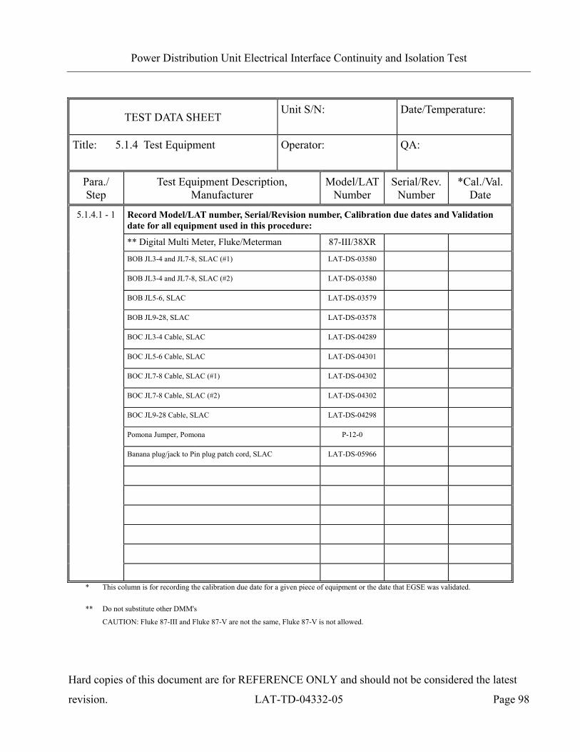
Power Distribution Unit Electrical Interface Continuity and Isolation Test
Hard copies of this document are for REFERENCE ONLY and should not be considered the latest
revision. LAT-TD-04332-05 Page 98
TEST DATA SHEET Unit S/N:
Date/Temperature:
Title: 5.1.4 Test Equipment Operator:
QA:
Para./ Step
Test Equipment Description, Manufacturer
Model/LATNumber
Serial/Rev. Number
*Cal./Val. Date
5.1.4.1 - 1 Record Model/LAT number, Serial/Revision number, Calibration due dates and Validation date for all equipment used in this procedure:
** Digital Multi Meter, Fluke/Meterman 87-III/38XR
BOB JL3-4 and JL7-8, SLAC (#1) LAT-DS-03580
BOB JL3-4 and JL7-8, SLAC (#2) LAT-DS-03580
BOB JL5-6, SLAC LAT-DS-03579
BOB JL9-28, SLAC LAT-DS-03578
BOC JL3-4 Cable, SLAC LAT-DS-04289
BOC JL5-6 Cable, SLAC LAT-DS-04301
BOC JL7-8 Cable, SLAC (#1) LAT-DS-04302
BOC JL7-8 Cable, SLAC (#2) LAT-DS-04302
BOC JL9-28 Cable, SLAC LAT-DS-04298
Pomona Jumper, Pomona P-12-0
Banana plug/jack to Pin plug patch cord, SLAC LAT-DS-05966
* This column is for recording the calibration due date for a given piece of equipment or the date that EGSE was validated.
** Do not substitute other DMM's
CAUTION: Fluke 87-III and Fluke 87-V are not the same, Fluke 87-V is not allowed.
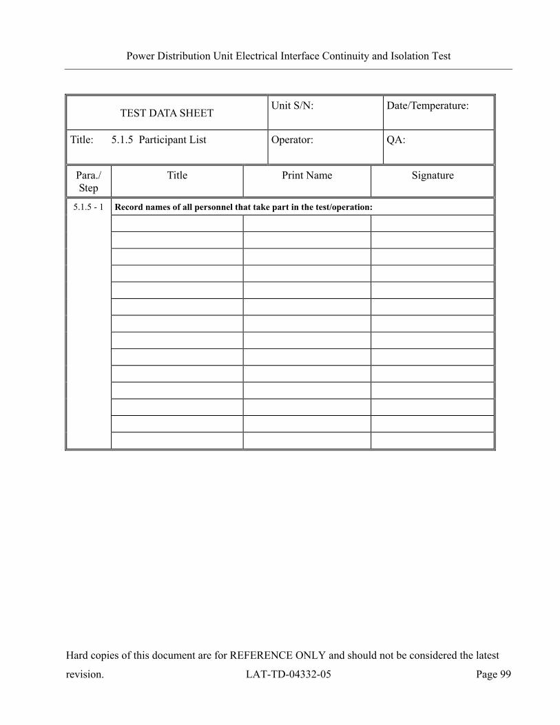
Power Distribution Unit Electrical Interface Continuity and Isolation Test
Hard copies of this document are for REFERENCE ONLY and should not be considered the latest
revision. LAT-TD-04332-05 Page 99
TEST DATA SHEET Unit S/N:
Date/Temperature:
Title: 5.1.5 Participant List Operator:
QA:
Para./ Step
Title Print Name Signature
Record names of all personnel that take part in the test/operation:
5.1.5 - 1

Power Distribution Unit Electrical Interface Continuity and Isolation Test
Hard copies of this document are for REFERENCE ONLY and should not be considered the latest
revision. LAT-TD-04332-05 Page 100
TEST DATA SHEET Unit S/N:
Date/Temperature:
Title: 5.2.1 Pre Operation Verifications Operator:
QA:
Para./ Step
Description Limits Unit Data
5.2.1 Pre-Operation Verifications
-1 Notify QAE. OK OK/NG -2 Test Readiness Review is done. OK OK/NG
Record the EUT equipment:
PDU Part number NA NA PDU LAT Bay location NA NA
-3
PDU Serial number, SN is the GLAT barcode.
NA NA
-4 LAT or EGSE power is off. OFF ON/OFF -5 Set DMM to autoranging for resistance. OK OK/NG -6 Measure DMM lead resistance. < 1.0 Ω -7 Measure BOB to ground. < 1.0 Ω -8 Remove all shorting plugs from BOBs. OK OK/NG -9 Measure EUT to ground. < 1.0 Ω
-10 All connector savers are installed on the flight connections.
OK OK/NG
-11 The test equipment and participant lists have been completed.
OK OK/NG
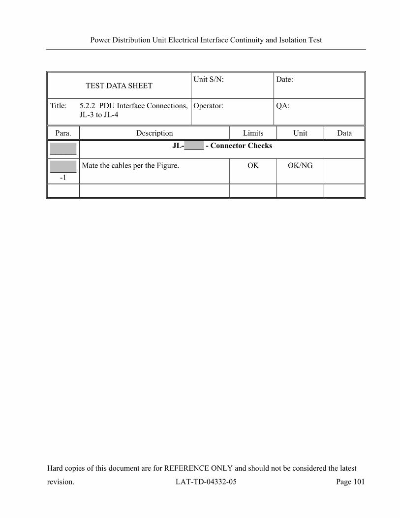
Power Distribution Unit Electrical Interface Continuity and Isolation Test
Hard copies of this document are for REFERENCE ONLY and should not be considered the latest
revision. LAT-TD-04332-05 Page 101
TEST DATA SHEET Unit S/N:
Date:
Title: 5.2.2 PDU Interface Connections, JL-3 to JL-4
Operator:
QA:
Para. Description Limits Unit Data
_____ JL-_____ - Connector Checks
_____ -1
Mate the cables per the Figure. OK OK/NG
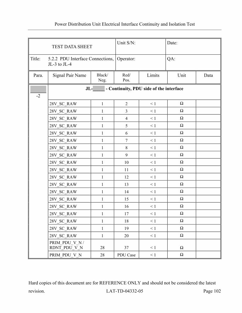
Power Distribution Unit Electrical Interface Continuity and Isolation Test
Hard copies of this document are for REFERENCE ONLY and should not be considered the latest
revision. LAT-TD-04332-05 Page 102
TEST DATA SHEET Unit S/N:
Date:
Title: 5.2.2 PDU Interface Connections, JL-3 to JL-4
Operator:
QA:
Para. Signal Pair Name Black/ Neg.
Red/ Pos.
Limits Unit Data
_____ -2
JL-_____ - Continuity, PDU side of the interface
28V_SC_RAW 1 2 < 1 Ω 28V_SC_RAW 1 3 < 1 Ω 28V_SC_RAW 1 4 < 1 Ω 28V_SC_RAW 1 5 < 1 Ω 28V_SC_RAW 1 6 < 1 Ω 28V_SC_RAW 1 7 < 1 Ω 28V_SC_RAW 1 8 < 1 Ω 28V_SC_RAW 1 9 < 1 Ω 28V_SC_RAW 1 10 < 1 Ω 28V_SC_RAW 1 11 < 1 Ω 28V_SC_RAW 1 12 < 1 Ω 28V_SC_RAW 1 13 < 1 Ω 28V_SC_RAW 1 14 < 1 Ω 28V_SC_RAW 1 15 < 1 Ω 28V_SC_RAW 1 16 < 1 Ω 28V_SC_RAW 1 17 < 1 Ω 28V_SC_RAW 1 18 < 1 Ω 28V_SC_RAW 1 19 < 1 Ω 28V_SC_RAW 1 20 < 1 Ω PRIM_PDU_V_N /
RDNT_PDU_V_N 28 37 < 1 Ω
PRIM_PDU_V_N 28 PDU Case < 1 Ω

Power Distribution Unit Electrical Interface Continuity and Isolation Test
Hard copies of this document are for REFERENCE ONLY and should not be considered the latest
revision. LAT-TD-04332-05 Page 103
TEST DATA SHEET Unit S/N:
Date:
Title: 5.2.2 PDU Interface Connections, JL-3 to JL-4
Operator:
QA:
Para. Signal Pair Name Black/ Neg.
Red/ Pos.
Limits Unit Data
_____ -2
JL-_____ - Continuity, PDU side of the interface
28V_SC_RET 64 65 < 1 Ω
28V_SC_RET 64 66 < 1 Ω
28V_SC_RET 64 58 < 1 Ω
28V_SC_RET 64 59 < 1 Ω
28V_SC_RET 64 60 < 1 Ω
28V_SC_RET 64 61 < 1 Ω
28V_SC_RET 64 62 < 1 Ω
28V_SC_RET 64 63 < 1 Ω
28V_SC_RET 64 51 < 1 Ω
28V_SC_RET 64 52 < 1 Ω
28V_SC_RET 64 53 < 1 Ω
28V_SC_RET 64 54 < 1 Ω
28V_SC_RET 64 55 < 1 Ω
28V_SC_RET 64 56 < 1 Ω
28V_SC_RET 64 57 < 1 Ω
28V_SC_RET 64 43 < 1 Ω
28V_SC_RET 64 44 < 1 Ω
28V_SC_RET 64 45 < 1 Ω
28V_SC_RET 64 46 < 1 Ω
28V_SC_RET / PRIM_PDU_V_N (RDNT_PDU_V_N) 64 28 45 – 55 Ω
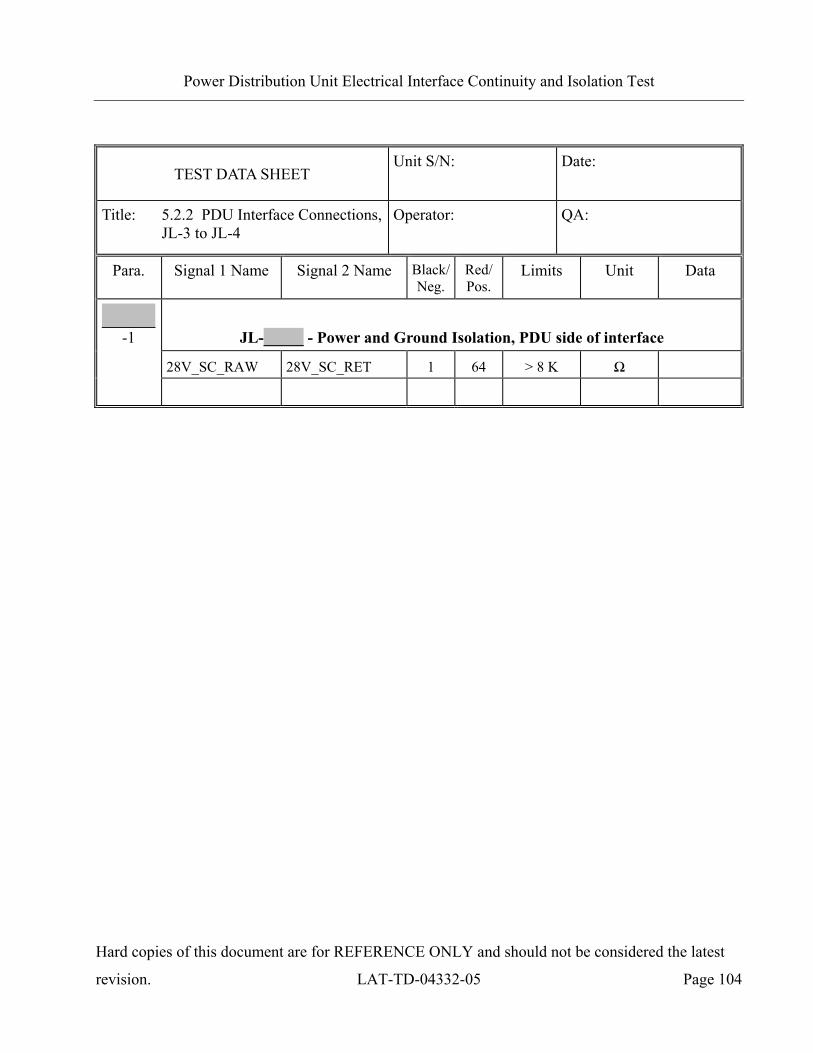
Power Distribution Unit Electrical Interface Continuity and Isolation Test
Hard copies of this document are for REFERENCE ONLY and should not be considered the latest
revision. LAT-TD-04332-05 Page 104
TEST DATA SHEET Unit S/N:
Date:
Title: 5.2.2 PDU Interface Connections, JL-3 to JL-4
Operator:
QA:
Para. Signal 1 Name Signal 2 Name Black/Neg.
Red/Pos.
Limits Unit Data
_____ -1 JL-_____ - Power and Ground Isolation, PDU side of interface
28V_SC_RAW 28V_SC_RET 1 64 > 8 K Ω

Power Distribution Unit Electrical Interface Continuity and Isolation Test
Hard copies of this document are for REFERENCE ONLY and should not be considered the latest
revision. LAT-TD-04332-05 Page 105
TEST DATA SHEET Unit S/N:
Date:
Title: 5.2.3 PDU Interface Connections, JL-5 to JL-6
Operator:
QA:
Para. Description Limits Unit Data
_____ JL-_____ - Connector Checks
_____ -1
Mate the cables per the Figure. OK OK/NG

Power Distribution Unit Electrical Interface Continuity and Isolation Test
Hard copies of this document are for REFERENCE ONLY and should not be considered the latest
revision. LAT-TD-04332-05 Page 106
TEST DATA SHEET Unit S/N:
Date:
Title: 5.2.3 PDU Interface Connections, JL-5 to JL-6
Operator:
QA:
Para. Signal Pair Name Black/Neg.
Red/ Pos.
Limits Unit Data
_____ -2
JL-_____ - Continuity, PDU side of the interface
GND 16 PDU Case < 1 Ω
N_SC_ON_PRIM_PDU_PRIM 1 31 < 1 Ω
N_SC_ON_RDNT_PDU_PRIM 2 32 < 1 Ω
N_GASU_ON_PRIM_PDU_PRIM 5 35 < 1 Ω
N_GASU_ON_RDNT_PDU_PRIM 6 36 < 1 Ω
N_SC_ON_PRIM_PDU_RDNT 7 37 < 1 Ω
N_SC_ON_RDNT_PDU_RDNT 8 38 < 1 Ω
N_GASU_ON_PRIM_PDU_RDNT 11 41 < 1 Ω
N_GASU_ON_RDNT_PDU_RDNT 12 42 < 1 Ω
GND 16 17 < 1 Ω
GND 16 20 < 1 Ω
GND 16 21 < 1 Ω
GND 16 22 < 1 Ω
GND 16 23 < 1 Ω
GND 16 26 < 1 Ω
GND 16 27 < 1 Ω

Power Distribution Unit Electrical Interface Continuity and Isolation Test
Hard copies of this document are for REFERENCE ONLY and should not be considered the latest
revision. LAT-TD-04332-05 Page 107
TEST DATA SHEET Unit S/N:
Date:
Title: 5.2.4 PDU Interface Connections, JL-7 to JL-8
Operator:
QA:
Para. Description Limits Unit Data
_____ JL-_____ - Connector Checks
_____ -1
Mate the cables per the Figure. OK OK/NG

Power Distribution Unit Electrical Interface Continuity and Isolation Test
Hard copies of this document are for REFERENCE ONLY and should not be considered the latest
revision. LAT-TD-04332-05 Page 108
TEST DATA SHEET Unit S/N:
Date:
Title: 5.2.4 PDU Interface Connections, JL-7 to JL-8
Operator:
QA:
Para. Signal Pair Name Black/Neg.
Red/ Pos.
Limits Unit Data
_____ -2
JL-_____ - Continuity, PDU side of the interface
GND 7 PDU Case < 1 Ω
GASU_DAQ_28V_PDU_PRIM 1 3 < 1 Ω
GASU_DAQ_28V_PDU_RDNT 40 42 < 1 Ω
GASU_ACD_28V_PDU_PRIM 21 23 < 1 Ω
GASU_ACD_28V_PDU_RDNT 60 62 < 1 Ω
GASU_RET_28V_PDU 2 4 < 1 Ω
GASU_RET_28V_PDU 2 22 < 1 Ω
GASU_RET_28V_PDU 2 24 < 1 Ω
GASU_RET_28V_PDU 2 41 < 1 Ω
GASU_RET_28V_PDU 2 43 < 1 Ω
GASU_RET_28V_PDU 2 61 < 1 Ω
GASU_RET_28V_PDU 2 63 < 1 Ω
GASU_RET_28V_PDU/GND 2 7 45 – 55 Ω
GND 7 46 < 1 Ω
GND 7 31 < 1 Ω
GND 7 70 < 1 Ω
GND (applies to JL8 ONLY) 7 35 < 1 Ω
GND (applies to JL8 ONLY) 7 37 < 1 Ω
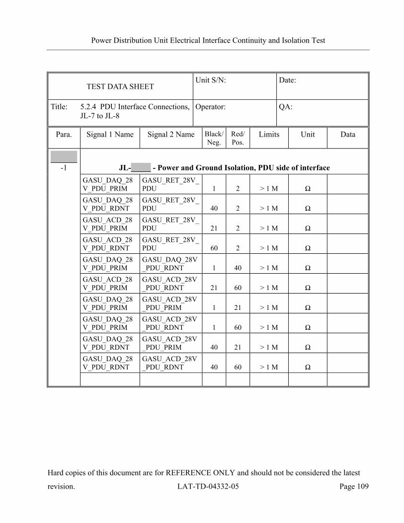
Power Distribution Unit Electrical Interface Continuity and Isolation Test
Hard copies of this document are for REFERENCE ONLY and should not be considered the latest
revision. LAT-TD-04332-05 Page 109
TEST DATA SHEET Unit S/N:
Date:
Title: 5.2.4 PDU Interface Connections, JL-7 to JL-8
Operator:
QA:
Para. Signal 1 Name Signal 2 Name Black/Neg.
Red/Pos.
Limits Unit Data
_____ -1 JL-_____ - Power and Ground Isolation, PDU side of interface
GASU_DAQ_28V_PDU_PRIM
GASU_RET_28V_PDU 1 2 > 1 M Ω
GASU_DAQ_28V_PDU_RDNT
GASU_RET_28V_PDU 40 2 > 1 M Ω
GASU_ACD_28V_PDU_PRIM
GASU_RET_28V_PDU 21 2 > 1 M Ω
GASU_ACD_28V_PDU_RDNT
GASU_RET_28V_PDU 60 2 > 1 M Ω
GASU_DAQ_28V_PDU_PRIM
GASU_DAQ_28V_PDU_RDNT 1 40 > 1 M Ω
GASU_ACD_28V_PDU_PRIM
GASU_ACD_28V_PDU_RDNT 21 60 > 1 M Ω
GASU_DAQ_28V_PDU_PRIM
GASU_ACD_28V_PDU_PRIM 1 21 > 1 M Ω
GASU_DAQ_28V_PDU_PRIM
GASU_ACD_28V_PDU_RDNT 1 60 > 1 M Ω
GASU_DAQ_28V_PDU_RDNT
GASU_ACD_28V_PDU_PRIM 40 21 > 1 M Ω
GASU_DAQ_28V_PDU_RDNT
GASU_ACD_28V_PDU_RDNT 40 60 > 1 M Ω

Power Distribution Unit Electrical Interface Continuity and Isolation Test
Hard copies of this document are for REFERENCE ONLY and should not be considered the latest
revision. LAT-TD-04332-05 Page 110
TEST DATA SHEET Unit S/N:
Date:
Title: 5.2.5 PDU Interface Connections, JL-9 to JL-11
Operator:
QA:
Para. Description Limits Unit Data
_____ JL-_____ - Connector Checks
_____ -1
Mate the cables per the Figure. OK OK/NG

Power Distribution Unit Electrical Interface Continuity and Isolation Test
Hard copies of this document are for REFERENCE ONLY and should not be considered the latest
revision. LAT-TD-04332-05 Page 111
TEST DATA SHEET Unit S/N:
Date:
Title: 5.2.5 PDU Interface Connections, JL-9 to JL-11
Operator:
QA:
Para. Signal Pair Name Black/ Neg.
Red/ Pos.
Limits Unit Data
_____ -2
JL-_____ - Continuity, PDU side of the interface
EPU_28V PRIM 1 2 < 1 Ω
EPU_28V RDNT 3 4 < 1 Ω
28VRET 5 6 < 1 Ω
28VRET 5 7 < 1 Ω
28VRET 5 8 < 1 Ω
TEST DATA SHEET Unit S/N:
Date:
Title: 5.2.5 PDU Interface Connections, JL-9 to JL-11
Operator:
QA:
Para. Signal 1 Name Signal 2 Name Black/Neg.
Red/Pos.
Limits Unit Data
_____ -1 JL-_____ - Power and Ground Isolation, PDU side of interface
EPU_28V PRIM 28VRET 1 5 > 1 M Ω
EPU_28V RDNT 28VRET 3 5 > 1 M Ω
EPU_28V PRIM EPU_28V RDNT 1 3 > 1 M Ω

Power Distribution Unit Electrical Interface Continuity and Isolation Test
Hard copies of this document are for REFERENCE ONLY and should not be considered the latest
revision. LAT-TD-04332-05 Page 112
TEST DATA SHEET Unit S/N:
Date:
Title: 5.2.6 PDU Interface Connections, JL-13 to JL-28
Operator:
QA:
Para. Description Limits Unit Data
_____ JL-_____ - Connector Checks
_____ -1
Mate the cables per the Figure. OK OK/NG

Power Distribution Unit Electrical Interface Continuity and Isolation Test
Hard copies of this document are for REFERENCE ONLY and should not be considered the latest
revision. LAT-TD-04332-05 Page 113
TEST DATA SHEET Unit S/N:
Date:
Title: 5.2.6 PDU Interface Connections, JL-13 to JL-28
Operator:
QA:
Para. Signal Pair Name Black/ Neg.
Red/ Pos.
Limits Unit Data
JL-_____ - Continuity, PDU side of the interface TEM_28V PRIM 1 2 < 1 Ω TEM_28V RDNT 3 4 < 1 Ω 28VRET 5 6 < 1 Ω 28VRET 5 7 < 1 Ω 28VRET 5 8 < 1 Ω
_____ -2
TEST DATA SHEET Unit S/N:
Date:
Title: 5.2.6 PDU Interface Connections, JL-13 to JL-28
Operator:
QA:
Para. Signal 1 Name Signal 2 Name Black/Neg.
Red/Pos.
Limits Unit Data
_____ -1 JL-_____ - Power and Ground Isolation, PDU side of interface
TEM_28V Prim 28VRET 1 5 > 1 M Ω
TEM_28V Rdnt 28VRET 3 5 > 1 M Ω
TEM_28V PRIM TEM_28V RDNT 1 3 > 1 M Ω

Power Distribution Unit Electrical Interface Continuity and Isolation Test
Hard copies of this document are for REFERENCE ONLY and should not be considered the latest
revision. LAT-TD-04332-05 Page 114
TEST DATA SHEET Unit S/N:
Date:
Title: 5.2.7 PDU Interface Interconnections, JL-3/JL-4 to JL-7 and JL-8
Operator:
QA:
Para. Description Limits Unit Data
5.2.7.1 JL-3 - Continuity, PDU side of the interface
-1 Mate the cables per the Figure. OK OK/NG

Power Distribution Unit Electrical Interface Continuity and Isolation Test
Hard copies of this document are for REFERENCE ONLY and should not be considered the latest
revision. LAT-TD-04332-05 Page 115
TEST DATA SHEET Unit S/N:
Date:
Title: 5.2.7 PDU Interface Interconnections, JL-3/JL-4 to JL-7 and JL-8
Operator:
QA:
Para. Signal Name Connector - Black/Neg.
Connector - Red/Pos.
Limits Unit Data
5.2.7.1 -2
JL-3 - Continuity, PDU side of the interface
JL7_GASU_T_P JL-3 - 29 JL-7 - 19 < 1 Ω
JL7_GASU_T_N JL-3 - 30 JL-7 - 20 < 1 Ω
JL7_GASU_2_5V_CRU_GEM_P JL-3 - 48 JL-7 - 38 < 1 Ω
JL7_GASU_2_5V_CRU_GEM_N JL-3 - 49 JL-7 - 39 < 1 Ω
JL7_GASU_3_3V_CRU_GEM_P JL-3 - 31 JL-7 - 14 < 1 Ω
JL7_GASU_3_3V_CRU_GEM_N JL-3 - 32 JL-7 - 34 < 1 Ω
-3 Mate to JL8. OK OK/NG
-4 JL8_GASU_T_P JL-3 - 38 JL-8 - 19 < 1 Ω
JL8_GASU_T_N JL-3 - 39 JL-8 - 20 < 1 Ω
JL8_GASU_2_5V_CRU_GEM_P JL-3 – 50 JL-8 - 38 < 1 Ω
JL8_GASU_2_5V_CRU_GEM_N JL-3 – 42 JL-8 - 39 < 1 Ω
JL8_GASU_3_3V_CRU_GEM_P JL-3 – 40 JL-8 - 14 < 1 Ω
JL8_GASU_3_3V_CRU_GEM_N JL-3 – 41 JL-8 - 34 < 1 Ω

Power Distribution Unit Electrical Interface Continuity and Isolation Test
Hard copies of this document are for REFERENCE ONLY and should not be considered the latest
revision. LAT-TD-04332-05 Page 116
TEST DATA SHEET Unit S/N:
Date:
Title: 5.2.7 PDU Interface Interconnections, JL-3/JL-4 to JL-7 and JL-8
Operator:
QA:
Para. Description Limits Unit Data
5.2.7.2 JL-4 - Continuity, PDU side of the interface
-1 Mate the cables per the Figure. OK OK/NG

Power Distribution Unit Electrical Interface Continuity and Isolation Test
Hard copies of this document are for REFERENCE ONLY and should not be considered the latest
revision. LAT-TD-04332-05 Page 117
TEST DATA SHEET Unit S/N:
Date:
Title: 5.2.7 PDU Interface Interconnections, JL-3/JL-4 to JL-7 and JL-8
Operator:
QA:
Para. Signal Name Connector - Black/Neg.
Connector - Red/Pos.
Limits Unit Data
5.2.7.2 JL-4 - Continuity, PDU side of the interface
-2 JL7_GASU_T_P JL-4 - 29 JL-7 - 58 < 1 Ω
JL7_GASU_T_N JL-4 - 30 JL-7 - 59 < 1 Ω
JL7_GASU_2_5V_CRU_GEM_P JL-4 - 48 JL-7 - 77 < 1 Ω
JL7_GASU_2_5V_CRU_GEM_N JL-4 - 49 JL-7 - 78 < 1 Ω
JL7_GASU_3_3V_CRU_GEM_P JL-4 - 31 JL-7 - 53 < 1 Ω
JL7_GASU_3_3V_CRU_GEM_N JL-4 - 32 JL-7 - 73 < 1 Ω
-3 Mate to JL8. OK OK/NG
-4 JL8_GASU_T_P JL-4 – 38 JL-8 - 58 < 1 Ω
JL8_GASU_T_N JL-4 – 39 JL-8 - 59 < 1 Ω
JL8_GASU_2_5V_CRU_GEM_P JL-4 – 50 JL-8 - 77 < 1 Ω
JL8_GASU_2_5V_CRU_GEM_N JL-4 – 42 JL-8 - 78 < 1 Ω
JL8_GASU_3_3V_CRU_GEM_P JL-4 – 40 JL-8 - 53 < 1 Ω
JL8_GASU_3_3V_CRU_GEM_N JL-4 - 41 JL-8 - 73 < 1 Ω

Power Distribution Unit Electrical Interface Continuity and Isolation Test
Hard copies of this document are for REFERENCE ONLY and should not be considered the latest
revision. LAT-TD-04332-05 Page 118
TEST DATA SHEET Unit S/N:
Date/Temperature:
Title: 5.3.1 Pre Operation Verifications Operator:
QA:
Para./ Step
Description Limits Unit Data
5.3.1 Pre-Operation Verifications
-1 Notify QAE. OK OK/NG -2 Test Readiness Review is done. OK OK/NG
Record the EUT equipment:
PDU Part number NA NA PDU LAT Bay location NA NA
-3
PDU Serial number, SN is the GLAT barcode.
NA NA
-4 LAT or EGSE power is OFF. OFF ON/OFF -5 Set DMM to autoranging for resistance. OK OK/NG -6 Measure DMM lead resistance. < 1.0 Ω -7 Measure BOB to ground. < 1.0 Ω -8 Remove all shorting plugs from BOBs. OK OK/NG -9 Measure EUT to ground. < 1.0 Ω
-10 All connector savers are installed on the flight connections.
OK OK/NG
-11 The test equipment and participant lists have been completed.
OK OK/NG
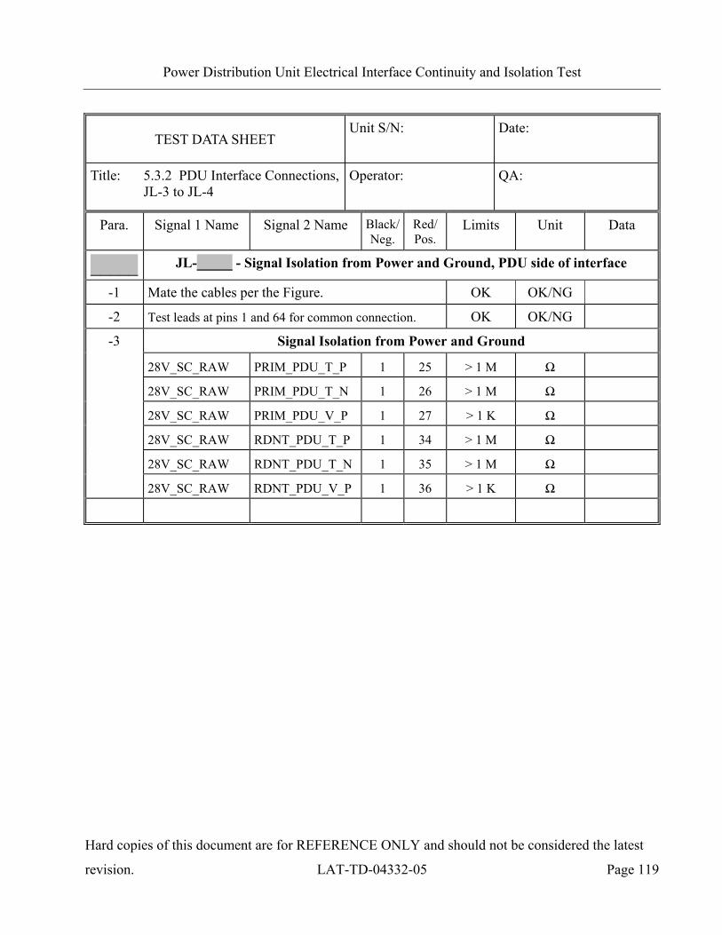
Power Distribution Unit Electrical Interface Continuity and Isolation Test
Hard copies of this document are for REFERENCE ONLY and should not be considered the latest
revision. LAT-TD-04332-05 Page 119
TEST DATA SHEET Unit S/N:
Date:
Title: 5.3.2 PDU Interface Connections, JL-3 to JL-4
Operator:
QA:
Para. Signal 1 Name Signal 2 Name Black/Neg.
Red/Pos.
Limits Unit Data
_____ JL-_____ - Signal Isolation from Power and Ground, PDU side of interface
-1 Mate the cables per the Figure. OK OK/NG
-2 Test leads at pins 1 and 64 for common connection. OK OK/NG
-3 Signal Isolation from Power and Ground
28V_SC_RAW PRIM_PDU_T_P 1 25 > 1 M Ω
28V_SC_RAW PRIM_PDU_T_N 1 26 > 1 M Ω
28V_SC_RAW PRIM_PDU_V_P 1 27 > 1 K Ω
28V_SC_RAW RDNT_PDU_T_P 1 34 > 1 M Ω
28V_SC_RAW RDNT_PDU_T_N 1 35 > 1 M Ω
28V_SC_RAW RDNT_PDU_V_P 1 36 > 1 K Ω

Power Distribution Unit Electrical Interface Continuity and Isolation Test
Hard copies of this document are for REFERENCE ONLY and should not be considered the latest
revision. LAT-TD-04332-05 Page 120
TEST DATA SHEET Unit S/N:
Date:
Title: 5.3.2 PDU Interface Connections, JL-3 to JL-4
Operator:
QA:
Para. Signal 1 Name Signal 2 Name Black/Neg.
Red/Pos.
Limits Unit Data
_____ -3
JL-_____ - Signal Isolation from Power and Ground, PDU side of interface
28V_SC_RAW JL7_GASU_T_P 1 29 > 1 M Ω
28V_SC_RAW JL7_GASU_T_N 1 30 > 1 M Ω
28V_SC_RAW
JL7_GASU_2_5V_CRU_GEM_P 1 48 > 1 M Ω
28V_SC_RAW
JL7_GASU_2_5V_CRU_GEM_N 1 49 > 1 M Ω
28V_SC_RAW
JL7_GASU_3_3V_CRU_GEM_P 1 31 > 1 M Ω
28V_SC_RAW
JL7_GASU_3_3V_CRU_GEM_N 1 32 > 1 M Ω
28V_SC_RAW JL8_GASU_T_P 1 38 > 1 M Ω
28V_SC_RAW JL8_GASU_T_N 1 39 > 1 M Ω
28V_SC_RAW
JL8_GASU_2_5V_CRU_GEM_P 1 50 > 1 M Ω
28V_SC_RAW
JL8_GASU_2_5V_CRU_GEM_N 1 42 > 1 M Ω
28V_SC_RAW
JL8_GASU_3_3V_CRU_GEM_P 1 40 > 1 M Ω
28V_SC_RAW
JL8_GASU_3_3V_CRU_GEM_N 1 41 > 1 M Ω
28V_SC_RAW Not Used 1 21 > 1 M Ω
28V_SC_RAW Not Used 1 22 > 1 M Ω
28V_SC_RAW Not Used 1 23 > 1 M Ω
28V_SC_RAW Not Used 1 24 > 1 M Ω
28V_SC_RAW Not Used 1 33 > 1 M Ω
28V_SC_RAW Not Used 1 47 > 1 M Ω
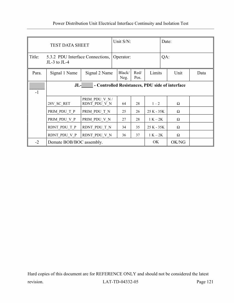
Power Distribution Unit Electrical Interface Continuity and Isolation Test
Hard copies of this document are for REFERENCE ONLY and should not be considered the latest
revision. LAT-TD-04332-05 Page 121
TEST DATA SHEET Unit S/N:
Date:
Title: 5.3.2 PDU Interface Connections, JL-3 to JL-4
Operator:
QA:
Para. Signal 1 Name Signal 2 Name Black/Neg.
Red/Pos.
Limits Unit Data
_____ -1
JL-_____ - Controlled Resistances, PDU side of interface
28V_SC_RET
PRIM_PDU_V_N / RDNT_PDU_V_N 64 28 1 – 2 Ω
PRIM_PDU_T_P PRIM_PDU_T_N 25 26 25 K - 35K Ω
PRIM_PDU_V_P PRIM_PDU_V_N 27 28 1 K – 2K Ω
RDNT_PDU_T_P RDNT_PDU_T_N 34 35 25 K - 35K Ω
RDNT_PDU_V_P RDNT_PDU_V_N 36 37 1 K – 2K Ω
-2 Demate BOB/BOC assembly. OK OK/NG
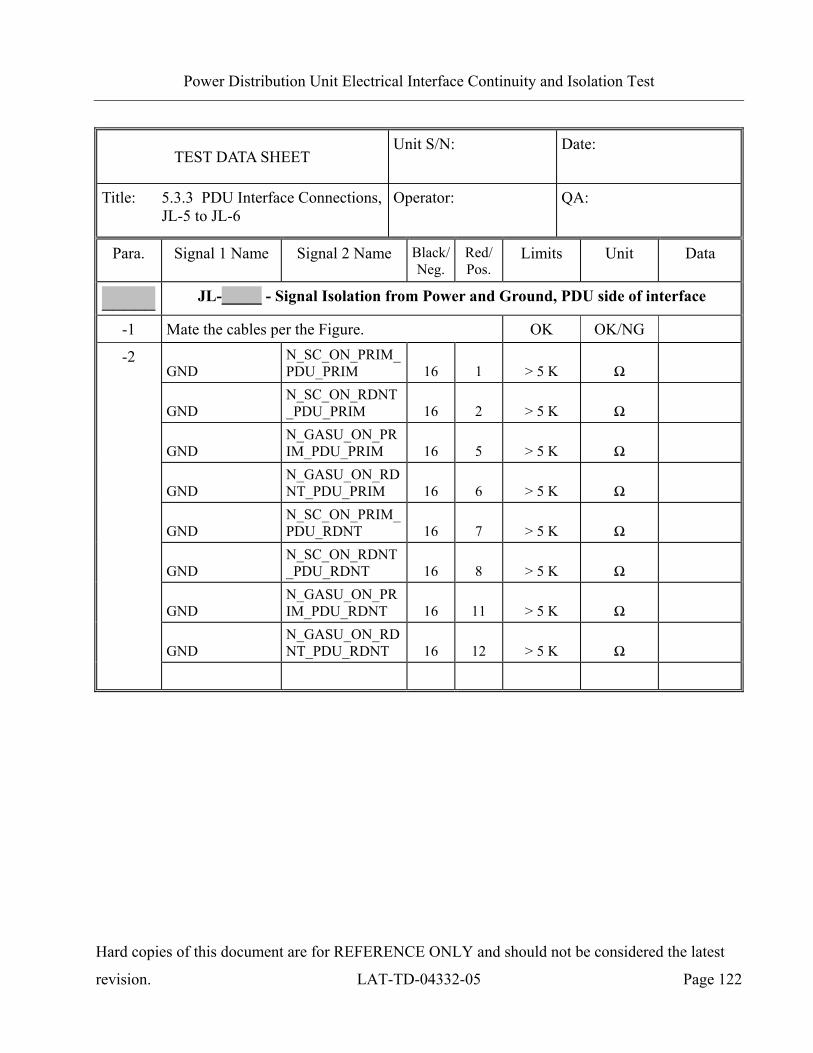
Power Distribution Unit Electrical Interface Continuity and Isolation Test
Hard copies of this document are for REFERENCE ONLY and should not be considered the latest
revision. LAT-TD-04332-05 Page 122
TEST DATA SHEET Unit S/N:
Date:
Title: 5.3.3 PDU Interface Connections, JL-5 to JL-6
Operator:
QA:
Para. Signal 1 Name Signal 2 Name Black/Neg.
Red/Pos.
Limits Unit Data
_____ JL-_____ - Signal Isolation from Power and Ground, PDU side of interface
-1 Mate the cables per the Figure. OK OK/NG
-2 GND
N_SC_ON_PRIM_PDU_PRIM 16 1 > 5 K Ω
GND
N_SC_ON_RDNT_PDU_PRIM 16 2 > 5 K Ω
GND
N_GASU_ON_PRIM_PDU_PRIM 16 5 > 5 K Ω
GND
N_GASU_ON_RDNT_PDU_PRIM 16 6 > 5 K Ω
GND
N_SC_ON_PRIM_PDU_RDNT 16 7 > 5 K Ω
GND
N_SC_ON_RDNT_PDU_RDNT 16 8 > 5 K Ω
GND
N_GASU_ON_PRIM_PDU_RDNT 16 11 > 5 K Ω
GND
N_GASU_ON_RDNT_PDU_RDNT 16 12 > 5 K Ω
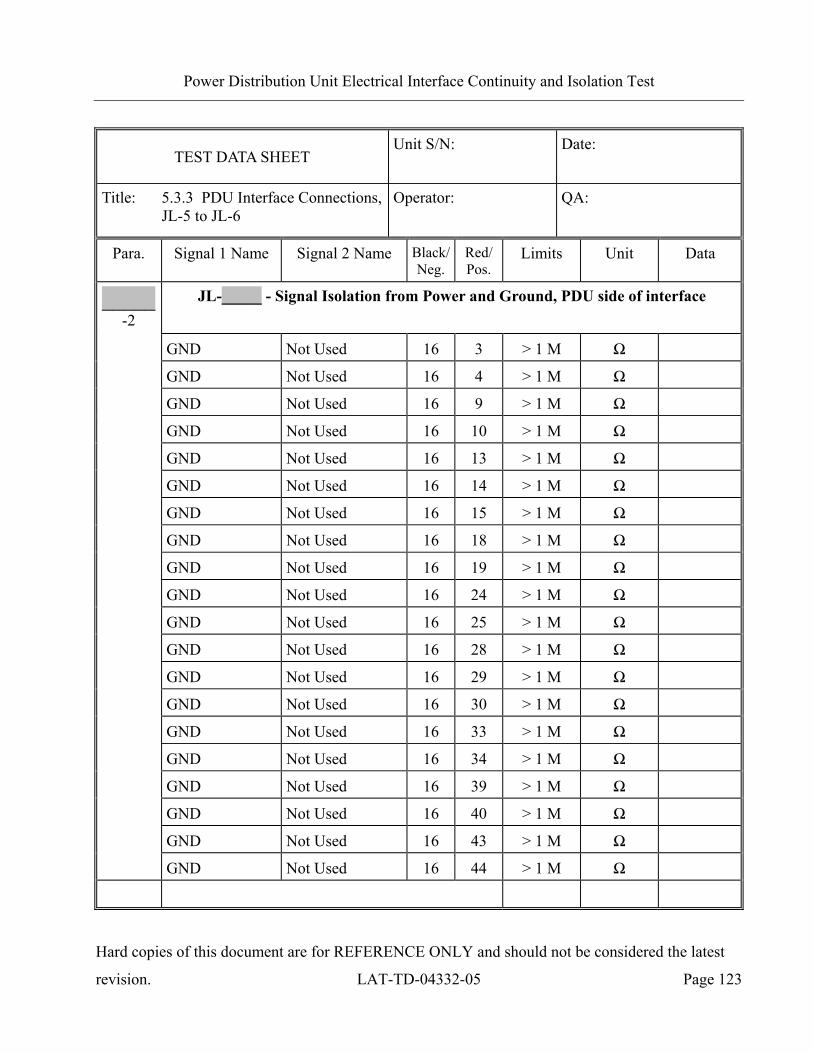
Power Distribution Unit Electrical Interface Continuity and Isolation Test
Hard copies of this document are for REFERENCE ONLY and should not be considered the latest
revision. LAT-TD-04332-05 Page 123
TEST DATA SHEET Unit S/N:
Date:
Title: 5.3.3 PDU Interface Connections, JL-5 to JL-6
Operator:
QA:
Para. Signal 1 Name Signal 2 Name Black/Neg.
Red/Pos.
Limits Unit Data
_____ -2
JL-_____ - Signal Isolation from Power and Ground, PDU side of interface
GND Not Used 16 3 > 1 M Ω
GND Not Used 16 4 > 1 M Ω
GND Not Used 16 9 > 1 M Ω
GND Not Used 16 10 > 1 M Ω
GND Not Used 16 13 > 1 M Ω
GND Not Used 16 14 > 1 M Ω
GND Not Used 16 15 > 1 M Ω
GND Not Used 16 18 > 1 M Ω
GND Not Used 16 19 > 1 M Ω
GND Not Used 16 24 > 1 M Ω
GND Not Used 16 25 > 1 M Ω
GND Not Used 16 28 > 1 M Ω
GND Not Used 16 29 > 1 M Ω
GND Not Used 16 30 > 1 M Ω
GND Not Used 16 33 > 1 M Ω
GND Not Used 16 34 > 1 M Ω
GND Not Used 16 39 > 1 M Ω
GND Not Used 16 40 > 1 M Ω
GND Not Used 16 43 > 1 M Ω
GND Not Used 16 44 > 1 M Ω
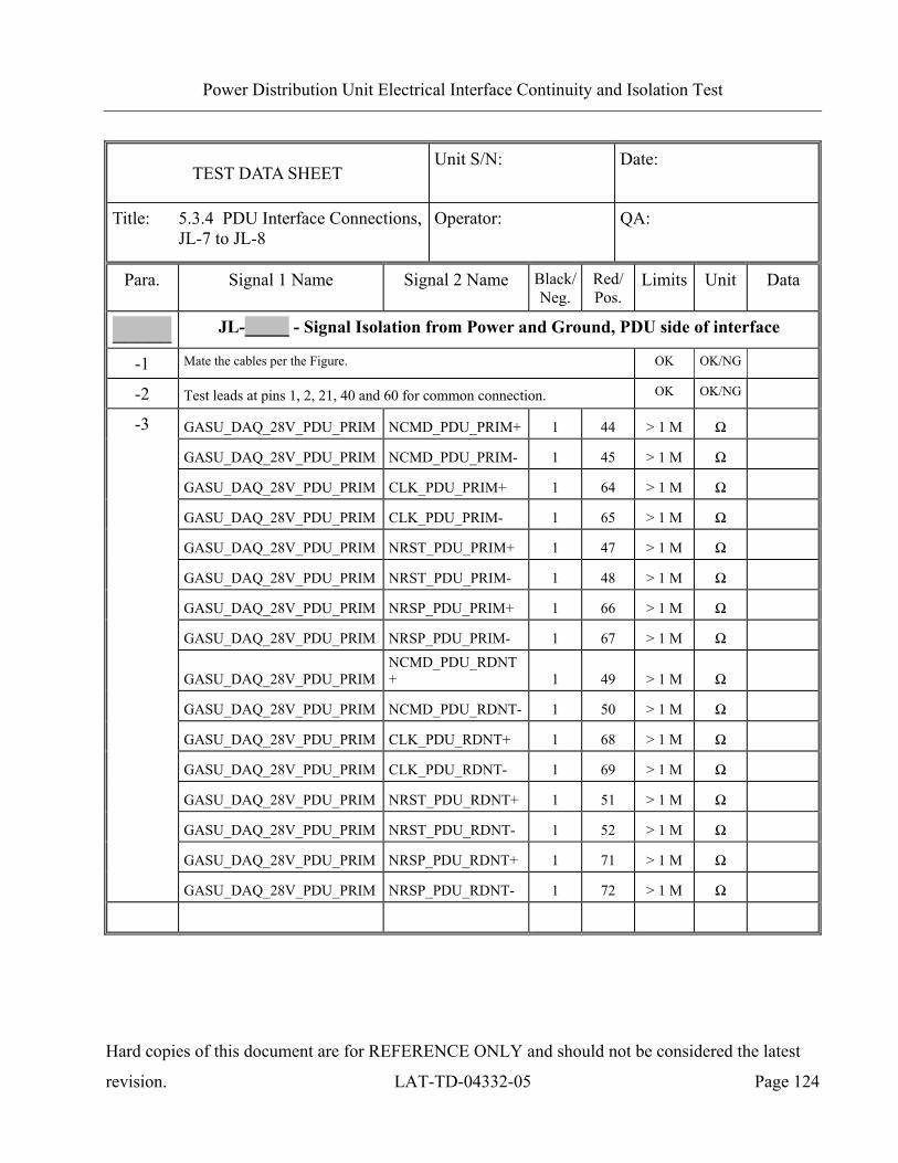
Power Distribution Unit Electrical Interface Continuity and Isolation Test
Hard copies of this document are for REFERENCE ONLY and should not be considered the latest
revision. LAT-TD-04332-05 Page 124
TEST DATA SHEET Unit S/N:
Date:
Title: 5.3.4 PDU Interface Connections, JL-7 to JL-8
Operator:
QA:
Para. Signal 1 Name Signal 2 Name Black/Neg.
Red/Pos.
Limits Unit Data
_____ JL-_____ - Signal Isolation from Power and Ground, PDU side of interface
-1 Mate the cables per the Figure. OK OK/NG
-2 Test leads at pins 1, 2, 21, 40 and 60 for common connection. OK OK/NG
-3 GASU_DAQ_28V_PDU_PRIM NCMD_PDU_PRIM+ 1 44 > 1 M Ω
GASU_DAQ_28V_PDU_PRIM NCMD_PDU_PRIM- 1 45 > 1 M Ω
GASU_DAQ_28V_PDU_PRIM CLK_PDU_PRIM+ 1 64 > 1 M Ω
GASU_DAQ_28V_PDU_PRIM CLK_PDU_PRIM- 1 65 > 1 M Ω
GASU_DAQ_28V_PDU_PRIM NRST_PDU_PRIM+ 1 47 > 1 M Ω
GASU_DAQ_28V_PDU_PRIM NRST_PDU_PRIM- 1 48 > 1 M Ω
GASU_DAQ_28V_PDU_PRIM NRSP_PDU_PRIM+ 1 66 > 1 M Ω
GASU_DAQ_28V_PDU_PRIM NRSP_PDU_PRIM- 1 67 > 1 M Ω
GASU_DAQ_28V_PDU_PRIM
NCMD_PDU_RDNT+ 1 49 > 1 M Ω
GASU_DAQ_28V_PDU_PRIM NCMD_PDU_RDNT- 1 50 > 1 M Ω
GASU_DAQ_28V_PDU_PRIM CLK_PDU_RDNT+ 1 68 > 1 M Ω
GASU_DAQ_28V_PDU_PRIM CLK_PDU_RDNT- 1 69 > 1 M Ω
GASU_DAQ_28V_PDU_PRIM NRST_PDU_RDNT+ 1 51 > 1 M Ω
GASU_DAQ_28V_PDU_PRIM NRST_PDU_RDNT- 1 52 > 1 M Ω
GASU_DAQ_28V_PDU_PRIM NRSP_PDU_RDNT+ 1 71 > 1 M Ω
GASU_DAQ_28V_PDU_PRIM NRSP_PDU_RDNT- 1 72 > 1 M Ω

Power Distribution Unit Electrical Interface Continuity and Isolation Test
Hard copies of this document are for REFERENCE ONLY and should not be considered the latest
revision. LAT-TD-04332-05 Page 125
TEST DATA SHEET Unit S/N:
Date:
Title: 5.3.4 PDU Interface Connections, JL-7 to JL-8
Operator:
QA:
Para. Signal 1 Name Signal 2 Name Black/Neg.
Red/Pos.
Limits Unit Data
_____ -3
JL-_____ - Signal Isolation from Power and Ground, PDU side of interface
GASU_DAQ_28V_PDU_PRIM
GASU_3_3V_CRU_GEM+ 1 14 > 1 M Ω
GASU_DAQ_28V_PDU_PRIM
GASU_3_3V_CRU_GEM- 1 34 > 1 M Ω
GASU_DAQ_28V_PDU_PRIM
GASU_3_3V_CRU_GEM+ 1 53 > 1 M Ω
GASU_DAQ_28V_PDU_PRIM
GASU_3_3V_CRU_GEM- 1 73 > 1 M Ω
GASU_DAQ_28V_PDU_PRIM GASU_DAQ_T1+ 1 19 > 1 M Ω
GASU_DAQ_28V_PDU_PRIM GASU_DAQ_T1- 1 20 > 1 M Ω
GASU_DAQ_28V_PDU_PRIM GASU_DAQ_T2+ 1 58 > 1 M Ω
GASU_DAQ_28V_PDU_PRIM GASU_DAQ_T2- 1 59 > 1 M Ω
GASU_DAQ_28V_PDU_PRIM
GASU_2_5V_CRU_GEM+ 1 38 > 1 M Ω
GASU_DAQ_28V_PDU_PRIM
GASU_2_5V_CRU_GEM- 1 39 > 1 M Ω
GASU_DAQ_28V_PDU_PRIM
GASU_2_5V_CRU_GEM+ 1 77 > 1 M Ω
GASU_DAQ_28V_PDU_PRIM
GASU_2_5V_CRU_GEM- 1 78 > 1 M Ω
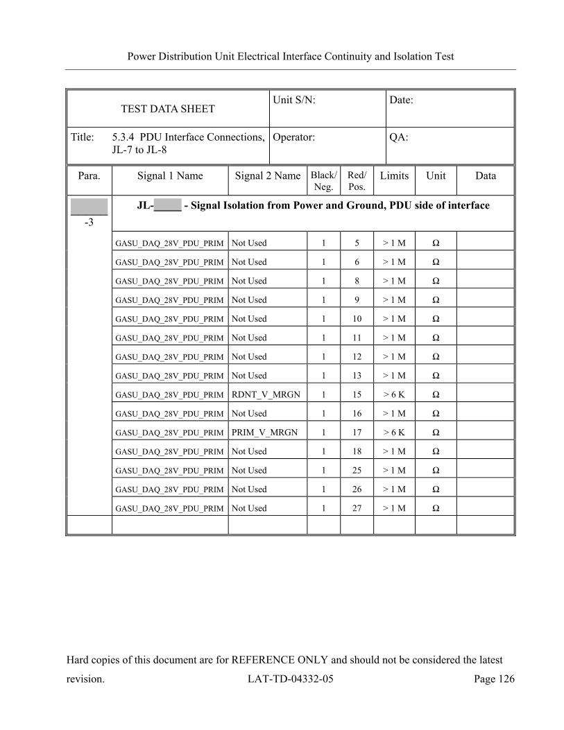
Power Distribution Unit Electrical Interface Continuity and Isolation Test
Hard copies of this document are for REFERENCE ONLY and should not be considered the latest
revision. LAT-TD-04332-05 Page 126
TEST DATA SHEET Unit S/N:
Date:
Title: 5.3.4 PDU Interface Connections, JL-7 to JL-8
Operator:
QA:
Para. Signal 1 Name Signal 2 Name Black/Neg.
Red/Pos.
Limits Unit Data
_____ -3
JL-_____ - Signal Isolation from Power and Ground, PDU side of interface
GASU_DAQ_28V_PDU_PRIM Not Used 1 5 > 1 M Ω
GASU_DAQ_28V_PDU_PRIM Not Used 1 6 > 1 M Ω
GASU_DAQ_28V_PDU_PRIM Not Used 1 8 > 1 M Ω
GASU_DAQ_28V_PDU_PRIM Not Used 1 9 > 1 M Ω
GASU_DAQ_28V_PDU_PRIM Not Used 1 10 > 1 M Ω
GASU_DAQ_28V_PDU_PRIM Not Used 1 11 > 1 M Ω
GASU_DAQ_28V_PDU_PRIM Not Used 1 12 > 1 M Ω
GASU_DAQ_28V_PDU_PRIM Not Used 1 13 > 1 M Ω
GASU_DAQ_28V_PDU_PRIM RDNT_V_MRGN 1 15 > 6 K Ω
GASU_DAQ_28V_PDU_PRIM Not Used 1 16 > 1 M Ω
GASU_DAQ_28V_PDU_PRIM PRIM_V_MRGN 1 17 > 6 K Ω
GASU_DAQ_28V_PDU_PRIM Not Used 1 18 > 1 M Ω
GASU_DAQ_28V_PDU_PRIM Not Used 1 25 > 1 M Ω
GASU_DAQ_28V_PDU_PRIM Not Used 1 26 > 1 M Ω
GASU_DAQ_28V_PDU_PRIM Not Used 1 27 > 1 M Ω

Power Distribution Unit Electrical Interface Continuity and Isolation Test
Hard copies of this document are for REFERENCE ONLY and should not be considered the latest
revision. LAT-TD-04332-05 Page 127
TEST DATA SHEET Unit S/N:
Date:
Title: 5.3.4 PDU Interface Connections, JL-7 to JL-8
Operator:
QA:
Para. Signal 1 Name Signal 2 Name
Black/Neg.
Red/Pos.
Limits Unit Data
_____ -3
JL-_____ - Signal Isolation from Power and Ground, PDU side of interface
GASU_DAQ_28V_PDU_PRIM Not Used 1 28 > 1 M Ω
GASU_DAQ_28V_PDU_PRIM Not Used 1 29 > 1 M Ω
GASU_DAQ_28V_PDU_PRIM Not Used 1 30 > 1 M Ω
GASU_DAQ_28V_PDU_PRIM Not Used 1 32 > 1 M Ω
GASU_DAQ_28V_PDU_PRIM Not Used 1 33 > 1 M Ω
GASU_DAQ_28V_PDU_PRIM
Not Used (applies to JL7 ONLY) 1 35 > 1 M Ω
GASU_DAQ_28V_PDU_PRIM Not Used 1 36 > 1 M Ω
GASU_DAQ_28V_PDU_PRIM
Not Used (applies to JL7 ONLY) 1 37 > 1 M Ω
GASU_DAQ_28V_PDU_PRIM Not Used 1 54 > 1 M Ω
GASU_DAQ_28V_PDU_PRIM Not Used 1 55 > 1 M Ω
GASU_DAQ_28V_PDU_PRIM Not Used 1 56 > 1 M Ω
GASU_DAQ_28V_PDU_PRIM Not Used 1 57 > 1 M Ω
GASU_DAQ_28V_PDU_PRIM Not Used 1 74 > 1 M Ω
GASU_DAQ_28V_PDU_PRIM Not Used 1 75 > 1 M Ω
GASU_DAQ_28V_PDU_PRIM Not Used 1 76 > 1 M Ω

Power Distribution Unit Electrical Interface Continuity and Isolation Test
Hard copies of this document are for REFERENCE ONLY and should not be considered the latest
revision. LAT-TD-04332-05 Page 128
TEST DATA SHEET Unit S/N:
Date:
Title: 5.3.4 PDU Interface Connections, JL-7 to JL-8
Operator:
QA:
Para. Signal 1 Name Signal 2 Name Black/Neg.
Red/Pos.
Limits Unit Data
_____ -1
JL-_____ - Controlled Resistances, PDU side of interface
NCMD_PDU_PRIM+ NCMD_PDU_PRIM- 44 45 95 - 105 Ω
CLK_PDU_PRIM+ CLK_PDU_PRIM- 64 65 95 - 105 Ω
NRST_PDU_PRIM+ NRST_PDU_PRIM- 47 48 95 - 105 Ω
NRSP_PDU_PRIM+ NRSP_PDU_PRIM- 66 67 > 35 K Ω
NCMD_PDU_RDNT+ NCMD_PDU_RDNT- 49 50 95 - 105 Ω
CLK_PDU_RDNT+ CLK_PDU_RDNT- 68 69 95 - 105 Ω
NRST_PDU_RDNT+ NRST_PDU_RDNT- 51 52 95 - 105 Ω
NRSP_PDU_RDNT+ NRSP_PDU_RDNT- 71 72 > 35 K Ω
GASU_RET_28V_PDU GND 2 7 45 – 55 Ω

Power Distribution Unit Electrical Interface Continuity and Isolation Test
Hard copies of this document are for REFERENCE ONLY and should not be considered the latest
revision. LAT-TD-04332-05 Page 129
TEST DATA SHEET Unit S/N:
Date:
Title: 5.3.5 PDU Interface Connections, JL-9 to JL-11
Operator:
QA:
Para. Signal 1 Name Signal 2 Name Black/Neg.
Red/Pos.
Limits Unit Data
_____ JL-_____ - Signal Isolation from Power and Ground, PDU side of interface
-1 Mate the cables per the Figure. OK OK/NG
-2 Test leads at pins 1, 3, and 5 for common connection. OK OK/NG
-3 EPU_28V prim EPU_V1_N 1 9 > 1 M Ω
EPU_28V prim EPU_T1_P 1 10 > 1 K Ω
EPU_28V prim EPU_T1_N 1 11 > 90 K Ω
EPU_28V prim EPU_T2_P 1 12 > 1 K Ω
EPU_28V prim EPU_T2_N 1 13 > 90 K Ω
EPU_28V prim EPU_V1_P 1 18 > 15 K Ω
EPU_28V prim EPU_V2_P 1 19 > 15 K Ω
EPU_28V prim EPU_V2_N 1 20 > 1 M Ω
EPU_28V prim Not Used 1 14 > 1 M Ω
EPU_28V prim Not Used 1 15 > 1 M Ω
EPU_28V prim Not Used 1 16 > 1 M Ω
EPU_28V prim Not Used 1 17 > 1 M Ω
EPU_28V prim Not Used 1 21 > 1 M Ω
EPU_28V prim Not Used 1 22 > 1 M Ω
EPU_28V prim Not Used 1 23 > 1 M Ω
EPU_28V prim Not Used 1 24 > 1 M Ω
EPU_28V prim Not Used 1 25 > 1 M Ω
EPU_28V prim Not Used 1 26 > 1 M Ω

Power Distribution Unit Electrical Interface Continuity and Isolation Test
Hard copies of this document are for REFERENCE ONLY and should not be considered the latest
revision. LAT-TD-04332-05 Page 130
TEST DATA SHEET Unit S/N:
Date:
Title: 5.3.6 PDU Interface Connections, JL-13 to JL-28
Operator:
QA:
Para. Signal 1 Name Signal 2 Name Black/Neg.
Red/Pos.
Limits Unit Data
_____ JL-_____ - Signal Isolation from Power and Ground, PDU side of interface
-1 Mate the cables per the Figure. OK OK/NG
-2 Test leads at pins 1, 3 and 5 for common connection. OK OK/NG
-3 TEM_28V prim TEM_V1_N 1 9 > 1 M Ω
TEM_28V prim TEM_PS_T1_P 1 10 > 1 K Ω
TEM_28V prim TEM_PS_T1_N 1 11 > 90 K Ω
TEM_28V prim TEM_PS_T2_P 1 12 > 1 K Ω
TEM_28V prim TEM_PS_T2_N 1 13 > 90 K Ω
TEM_28V prim TEM_T1_P 1 14 > 1 K Ω
TEM_28V prim TEM_T1_N 1 15 > 90 K Ω
TEM_28V prim TEM_T2_P 1 16 > 1 K Ω
TEM_28V prim TEM_T2_N 1 17 > 90 K Ω
TEM_28V prim TEM_V1_P 1 18 > 15 K Ω
TEM_28V prim TEM_V2_P 1 19 > 15 K Ω
TEM_28V prim TEM_V2_N 1 20 > 1 M Ω
TEM_28V prim Not Used 1 21 > 1 M Ω
TEM_28V prim Not Used 1 22 > 1 M Ω
TEM_28V prim Not Used 1 23 > 1 M Ω
TEM_28V prim Not Used 1 24 > 1 M Ω
TEM_28V prim Not Used 1 25 > 1 M Ω
TEM_28V prim Not Used 1 26 > 1 M Ω

Power Distribution Unit Electrical Interface Continuity and Isolation Test
Hard copies of this document are for REFERENCE ONLY and should not be considered the latest
revision. LAT-TD-04332-05 Page 131
Appendix B (Connector Mate/Demate Log)

Power Distribution Unit Electrical Interface Continuity and Isolation Test
Hard copies of this document are for REFERENCE ONLY and should not be considered the latest revision.
LAT-TD-04332-04 Page 132
The Excel Mate/Demate log form that is below is the actual Excel file imported into this word document. You can copy and paste it into a
folder and then open it as an Excel worksheet.
CONNECTOR MATE / DEMATEUNIT DESCRIPTION:
Connector(s) Authorized by Date
Mate or
De-mate
Flight or Test
Verify Power Off
Connector Reference Designator Procedure & para or NCR M/D/Y M or D F or T Emp. ID# *Emp. ID# QA * Emp ID# QA * Emp. ID# QA
*Personnel that is Mate/Demate certified.
Connector/Bracket R/D:
Pre-mate Inspect ESD Bleed and Connector Mate
Final Inspect Fasteners Torqued,
Witness Stripe applied