document format for quintessa - gnssn home document… · web viewthis type of uncertainty is...
TRANSCRIPT

Extension of the IAEA’s GSA for the Borehole Disposal Concept to include High Activity SourcesTask 3: Screening of GSA FEPs
R H Little
QRS-1668A-TN3Version 1.0 (draft)
November 2014

Document History
Title: Extension of the IAEA’s GSA for the Borehole Disposal Concept to include High Activity Sources
Subtitle: Task 3: Screening of GSA FEPsClient: IAEADocument Number: QRS-1668A-TN3
Version Number: Version 0.2 (draft) Date: November 2014Notes: Produced in light of FEPs review meeting involving Alex
Bond, Richard Little and Richard Metcalfe on 24th
November 2014Prepared by: Richard LittleReviewed by: Richard Metcalfe and Alex Bond
Approved by: Richard Little

QRS-1668A-TN3, Version 1.0 (draft)
Contents
1 Introduction 1
2 Screening of the General FEP List from the GSA 2
3 Screening of the Detailed Near-field FEP List from the GSA 12
4 Conclusions 56
References 57

QRS-1668A-TN3, Version 1.0 (draft)
1 IntroductionThe draft IAEA publication “Generic Post-closure Safety Assessment for the Borehole Disposal of Disused Sealed Sources” (the GSA) (IAEA, 2013) considers the post-closure impacts of the disposal of disused sealed radioactive sources using the Borehole Disposal Concept (BDC). Table 17 of the GSA notes that there is no explicit consideration in the GSA of radiolysis, criticality or thermal effects since such effects are considered to be insignificant for the typical inventories to be disposed. However, there are certain high activity sources, such as the Category 1 and 2 sources, for which it might be necessary to consider such effects. In addition, the calculations undertaken in the GSA are performed for a reference design with fixed dimensions for the capsule and disposal container (Table 5 of the GSA). It is recognised that capsules and disposal containers with alternative dimensions might be used in order to accommodate Category 1 and 2 sources. Changing the dimensions of the capsule/disposal container will impact on steel and concrete thicknesses which in turn will impact failure times. Therefore, it is also necessary to assess the impacts of alternative dimensions. The present project addresses the potential impacts of the disposal of high activity radioactive sources on the post-closure safety of the BDC. The results of this project will be used to determine the need, if any, for additional work. The project relates only to post-closure impacts; operational safety issues associated with the disposal of high activity sources in the BDC and the use of alternative dimensions for capsules and disposal containers is beyond the scope of the present project. This technical note documents the third task in the project; the screening of the lists of features, events and processes considered in the GSA. Appendices IV and V of IAEA (2013) provide a general FEP list and a detailed near-field FEP list considered in the GSA, respectively. The potential impacts of the Category 1 and 2 sources on the FEPs in these two lists are discussed in Section 2 (the general FEP list) and Section 3 (the detailed near-field FEP list). Conclusions are presented in Section 4.

QRS-1668A-TN3, Version 1.0 (draft)
2 Screening of the General FEP List from the GSA
The general FEP list given in Appendix IV of IAEA (2013) is reproduced below with additions to the text resulting from the consideration of Category 1 and 2 sources identified using underlining and red font. Unless stated otherwise, the references to section, appendix, box, table and figure numbers in Table2.1 relate to the sections, appendices, boxes, tables and figures in IAEA (2013).
Table 2.1: GSA General FEP List Screened for Category 1 and 2 Sources
0 ASSESSMENT CONTEXT FACTORS
0.0 Assessment Purpose – Yes, see Section 2.2 for the five main purposes of the assessment. Note that the current study focuses on the disposal of Category 1 and 2 sources.
0.0 Regulatory Requirements and Exclusions
1 0.2.01 Protection of human health and the environment – Yes, see Sections 2.2 and 2.4, especially Box 1 for protection objective and criteria. Impacts on non-human biota and non-radiological impacts are considered to be beyond the scope of the current study, so the focus is on radiological impacts upon human health.
2 0.2.02 Phases of disposal – Yes, see Sections 2.2 and 2.7. Assessment is of the post-closure phase, although it is recognized that operational and closure issues need to be considered when assessing post-closure safety.
3 0.2.03 Technical Requirements – Yes, see Sections 2.2 and 2.5. End points considered are waste activity levels expressed as total activity values and per waste package activity values. Calculations in the current study are based on maximum potential inventories of Co-60 and Cs-137 found in Category 1 and 2 sources. Output of assessment will help provide information on suitable inventories, engineering, institutional control period and hydrochemical characteristics.
0.0 Assessment Philosophy
4 0.3.01 Assessment approach – Yes, see Section 2.6. The ISAM Safety Assessment Approach is being used, consistent with best international practice.
0.3.02 Uncertainties, treatment of
5 0.3.02.01
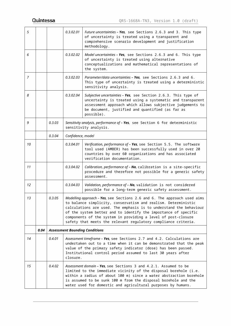
Future uncertainties – Yes, see Sections 2.6.3 and 3. This type of uncertainty is treated using a transparent and comprehensive scenario development and justification methodology.
6 0.3.02.02
Model uncertainties – Yes, see Sections 2.6.3 and 6. This type of uncertainty is treated using alternative conceptualizations and mathematical representations of the system.

QRS-1668A-TN3, Version 1.0 (draft)
7 0.3.02.03
Parameter/data uncertainties – Yes, see Sections 2.6.3 and 6. This type of uncertainty is treated using a deterministic sensitivity analysis.
8 0.3.02.04
Subjective uncertainties – Yes, see Section 2.6.3. This type of uncertainty is treated using a systematic and transparent assessment approach which allows subjective judgements to be document, justified and quantified (as far as possible).
9 0.3.03 Sensitivity analysis, performance of – Yes, see Section 6 for deterministic sensitivity analysis.
0.3.04 Confidence, model
10 0.3.04.01
Verification, performance of – Yes, see Section 5.5. The software tool used (AMBER) has been successfully used in over 20 countries by over 60 organizations and has associated verification documentation.
11 0.3.04.02
Calibration, performance of – No, calibration is a site-specific procedure and therefore not possible for a generic safety assessment.
12 0.3.04.03
Validation, performance of – No, validation is not considered possible for a long-term generic safety assessment.
13 0.3.05 Modelling approach – Yes, see Sections 2.6 and 6. The approach used aims to balance simplicity, conservatism and realism. Deterministic calculations are used. The emphasis is to understand the behaviour of the system better and to identify the importance of specific components of the system in providing a level of post-closure safety that meets the relevant regulatory compliance criteria.
0.0 Assessment Bounding Conditions
14 0.4.01 Assessment timeframe – Yes, see Sections 2.7 and 4.2. Calculations are undertaken out to a time when it can be demonstrated that the peak value of the primary safety indicator (dose) has been passed. Institutional control period assumed to last 30 years after closure.
15 0.4.02 Assessment domain – Yes, see Sections 3 and 4.2.1. Assumed to be limited to the immediate vicinity of the disposal borehole (i.e. within a radius of about 100 m) since a water abstraction borehole is assumed to be sunk 100 m from the disposal borehole and the water used for domestic and agricultural purposes by humans.
16 0.4.03 Future human action assumptions – Yes, see Sections 3.3 and 4.2.1. No consideration is given to the development of new societal structures and technologies.
17 0.4.04 Future human behaviour (target group) assumptions – Yes, see Sections 3.3 and 4.2.1. It is assumed that humans are exposed once institutional control of the site is lost either due to use contaminated groundwater abstracted from a borehole sunk 100 m from the disposal borehole, or due inhalation of contaminated gas in dwelling constructed directly above the disposal borehole.
18 0.4.05 Target audience (Stakeholder involvement) – Yes, see Section 2.3. Two audiences are considered – “developers” and “regulators”.
19 0.4.06 Assessment endpoints – Yes, see Sections 2.5 and 6. Primary end points are waste activity levels, which can be expressed as total activity values and per waste package activity values. For the current study on Category 1 and 2 sources, the primary end point is the dose arising from the disposal of the Co-60 and Cs-137 inventories.
QRS-1668A-TN3, Version 1.0 (draft)
20 0.4.07 Dose response assumptions – No, see Section 2.5. Risks of deleterious health effects are not considered as end points in the current study.
21 0.4.08 Results, presentation of – Yes, see Section 6. Results presented in tabular form.
22 0.4.09 Disposal Facility Assumptions – Yes, see Sections 3.1 and 4.2.1. It is assumed that the disposal borehole is constructed, operated and closed as planned. Information relating to the Category 1 and 2 sources considered in the current study is provided in Section 3 of Little and Thatcher (2014).
1 EXTERNAL FACTORS
1.1 Disposal Facility Factors
23 1.1.01 Investigations, site – Yes, although the assessment is generic and therefore it is assumed that there is no site-specific information available from site investigation (see Section 3.2), data (e.g. hydraulic gradients, conductivities, porosities) are presented in Section 3.2 that implicitly assumed that there has been some site investigation of the synthesised sites. It is assumed that any investigation boreholes have been appropriately backfilled and do not compromise the long-term safety of the disposal system.
24 1.1.02 Design, disposal facility – Yes, see Section 3.1.2 and Table 4. It is assumed that the disposal borehole is designed with appropriate safety features and functions. Relevant information for the Category 1 and 2 sources considered in the current study is provided in Section 3 of Little and Thatcher (2014).
25 1.1.03 Schedule and planning – Yes, see Sections 3.1.2 and 4.2.1. It is assumed that the disposal borehole is constructed, operated and closed as planned.
26 1.1.04 Construction, disposal facility – Yes, see Sections 3.1.2 and 4.2.1. It is assumed that the disposal borehole is constructed as planned.
27 1.1.05 Operation, disposal facility – Yes, see Sections 3.1.2 and 4.2.1. It is assumed that the disposal borehole is operated as planned.
28 1.1.06 Closure, disposal facility – Yes, see Sections 3.1.2 and 4.2.1. It is assumed that the disposal borehole is closed as planned.
29 1.1.07 Institutional controls – Yes, see Sections 2.7 and 4.2.1. It is assumed that institutional controls are in place for a period of 30 years after closure.
30 1.1.08 Quality assurance – Yes, see Section 4.2.1. It is assumed that appropriate quality assurance is applied to the design, construction, operation and closure of the disposal borehole.
31 1.1.09 Administrative control, disposal facility – Yes, see Sections 2.7 and 4.2.1. It is assumed that institutional controls are in place during the construction, operation and closure of the disposal borehole and for a period of 30 years after closure.
32 1.1.10 Accidents and unplanned events – No, see Section 4.2.1. It is assumed that the disposal borehole is closed as planned and there are no accidents or unplanned events.
33 1.1.11 Retrievability – No, see Section 3.1.2. Each waste package is backfilled into the borehole immediately following its emplacement.
34 1.1.12 Motivation and knowledge issues – Yes, see Section 4.2.1. It is assumed that no markers are fixed at the site to reveal the location of a radioactive waste disposal facility but land use controls are in place during the institutional control period.

QRS-1668A-TN3, Version 1.0 (draft)
35 1.1.13 Nuclear Criticality – No, such effects are considered to be insignificant for the typical inventories of fissile radionuclides to be disposed. Given that the high activity sources to be disposed in the borehole comprise Co-60 and Cs-137 and other non-fissile radionuclides (see Little and Thatcher, 2014), criticality is not an issue that needs to be considered even when evaluating the disposal of these sources.
1.2 Geological Processes and Effects
36 1.2.01 Tectonic movement – No, see Sections 3.2 and 4.2.1. It is assumed that the disposal borehole is located in a geologically stable area with no or extremely limited tectonic activity over the timescales of interest in the safety assessment.
37 1.2.02 Orogeny – No, see Sections 3.2 and 4.2.1. It is assumed that the disposal borehole is located in geologically stable area and there is no orogenic activity over the timescales of interest in the safety assessment.
38 1.2.03 Seismicity – No, see Sections 3.2 and 4.2.1. It is assumed that the disposal borehole is located in a geologically stable area with no or extremely limited seismic activity over the timescales of interest in the safety assessment.
39 1.2.04 Volcanic and magmatic activity – No, see Sections 3.2 and 4.2.1. It is assumed that the disposal borehole is located in geologically stable area and there is no volcanic and magmatic activity over the timescales of interest in the safety assessment.
40 1.2.05 Metamorphism – No, see Sections 3.2 and 4.2.1. It is assumed that the disposal borehole is located in geologically stable area and there is no metamorphic activity over the timescales of interest in the safety assessment.
41 1.2.06 Hydrothermal activity – No, see Sections 3.2 and 4.2.1. It is assumed that the disposal borehole is located in geologically stable area and there is no hydrothermal activity over the timescales of interest in the safety assessment.
42 1.2.07 Erosion and sedimentation – Yes, see Sections 3.2, 3.3, 4.1 and 4.2.1. It is assumed that there is gradual net erosion on a regional and local scale.
43 1.2.08 Diagenesis – No, diagenesis is not considered to be a significant process affecting the disposal system over the depths and timescales of interest in the safety assessment.
44 1.2.09 Pedogenesis – Yes, see Section 3.3 and 4.2.1. Need to consider soil contaminated by irrigation water.
45 1.2.10 Salt diapirism and dissolution – No, assume disposal borehole is located in an area that has no natural resources requiring excavation by extensive surface excavation or underground mining (see Section 3.2).
46 1.2.11 Undetected geological features – No, see Section 4.1. The geosphere is assumed to be as described in Section 3.2 with no unexpected features, processes or events.
47 1.2.12 Hydrological/hydrogeological response to geological changes – No, see Sections 3.2 and 4.2.1. It is assumed that the disposal borehole is located in geologically stable area and there are no significant geological changes over the timescales of interest in the safety assessment.
48 1.2.13 Geomorphologic responds to geological changes – No, see Sections 3.2 and 4.2.1. It is assumed that the disposal borehole is located in geologically and geomorphologically stable area and there are no significant changes over the timescales of interest in the safety assessment.

QRS-1668A-TN3, Version 1.0 (draft)
1.3 Climate Processes and Effects
49 1.3.01 Climate change, global – No, see Section 4.1. Constant climate conditions are assumed (a simplifying assumption).
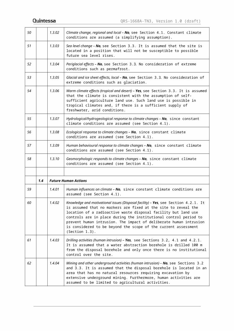
50 1.3.02 Climate change, regional and local – No, see Section 4.1. Constant climate conditions are assumed (a simplifying assumption).
51 1.3.03 Sea level change – No, see Section 3.3. It is assumed that the site is located in a position that will not be susceptible to possible future sea level rises.
52 1.3.04 Periglacial effects – No, see Section 3.3. No consideration of extreme conditions such as permafrost.
53 1.3.05 Glacial and ice sheet effects, local – No, see Section 3.3. No consideration of extreme conditions such as glaciation.
54 1.3.06 Warm climate effects (tropical and desert) – Yes, see Section 3.3. It is assumed that the climate is consistent with the assumption of self-sufficient agriculture land use. Such land use is possible in tropical climates and, if there is a sufficient supply of freshwater, arid conditions.
55 1.3.07 Hydrological/hydrogeological response to climate changes – No, since constant climate conditions are assumed (see Section 4.1).
56 1.3.08 Ecological response to climate changes – No, since constant climate conditions are assumed (see Section 4.1).
57 1.3.09 Human behavioural response to climate changes – No, since constant climate conditions are assumed (see Section 4.1).
58 1.3.10 Geomorphologic responds to climate changes – No, since constant climate conditions are assumed (see Section 4.1).
1.4 Future Human Actions
59 1.4.01 Human influences on climate – No, since constant climate conditions are assumed (see Section 4.1).
60 1.4.02 Knowledge and motivational issues (Disposal facility) – Yes, see Section 4.2.1. It is assumed that no markers are fixed at the site to reveal the location of a radioactive waste disposal facility but land use controls are in place during the institutional control period to prevent human intrusion. The impact of deliberate human intrusion is considered to be beyond the scope of the current assessment (Section 1.3).
61 1.4.03 Drilling activities (human intrusion) – Yes, see Sections 3.2, 4.1 and 4.2.1. It is assumed that a water abstraction borehole is drilled 100 m from the disposal borehole and only once there is no institutional control over the site.
62 1.4.04 Mining and other underground activities (human intrusion) – No, see Sections 3.2 and 3.3. It is assumed that the disposal borehole is located in an area that has no natural resources requiring excavation by extensive underground mining. Furthermore, human activities are assumed to be limited to agricultural activities.
63 1.4.05 Un-intrusive site investigation – No, see Sections 3.2 and 3.3. It is assumed that the disposal borehole is located in an area that has no natural resources and human activities are assumed to be limited to agricultural activities. Therefore, it is considered that there is no un-intrusive site investigation.
64 1.4.06 Surface excavations – No, see Sections 3.2 and 3.3. The disposal zone is assumed to be at least 30 m below the ground surface and it is considered that any surface excavations associated with agricultural land use will not extend down to such depths.

QRS-1668A-TN3, Version 1.0 (draft)
65 1.4.07 Pollution – No, it is assumed that human activities do not significantly affect the disposal system.
66 1.4.08 Site Development – Yes, see Sections 3.2, 4.1 and 4.2.1. It is assumed that a water abstraction borehole is drilled 100 m from the disposal borehole and only once there is no institutional control over the site.
67 1.4.09 Archaeology – No, see Section 3.3. Human activities are assumed to be limited to agricultural activities.
68 1.4.10 Water management (wells, reservoirs, dams) – Yes, see Sections 3.2, 4.1 and 4.2.1. It is assumed that a water abstraction borehole is drilled 100 m from the disposal borehole and only once there is no institutional control over the site.
69 1.4.11 Social and institutional developments – Yes, see Sections 2.7, 3.3 and 4.2.1. It is assumed that land use controls are in place during the institutional control period to prevent human intrusion. But at the end of the period, controls are assumed to be no longer in place.
70 1.4.12 Technological developments – No, see Sections 3.3 and 4.2.1. No consideration is given to the development of new technologies.
71 1.4.13 Remedial actions – No, see Sections 2.7 and 4.2.1. It is assumed that the disposal system performs appropriately and so there is no need for remedial actions during the period of active institutional control.
72 1.4.14 Explosions and crashes – No, it is assumed that there are no explosions or crashes.
2 DISPOSAL SYSTEM DOMAIN FACTORS
2.1 Waste, Waste Form & Engineered Features
73 2.1.1 Inventory, waste – Yes, see Section 3.1.1 and Appendix V. Assume a unit inventory of 1 TBq per waste package of each of the emboldened radionuclides in Table 3 is disposed in the borehole. For the high activity sources considered in the current study, an inventory of up to 350 TBq of Co-60 per capsule and up to 470 TBq of Cs-137 per capsule is assumed (see Section 5.2 of Little and Thatcher, 2014).
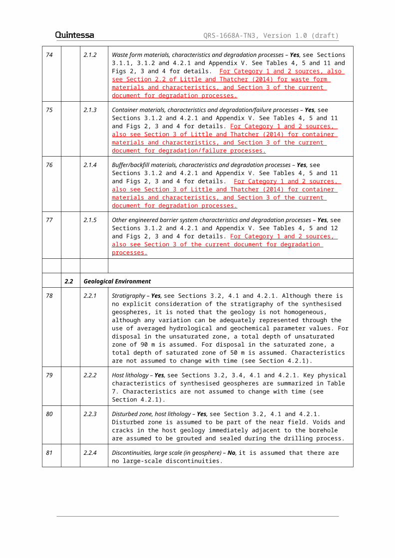
74 2.1.2 Waste form materials, characteristics and degradation processes – Yes, see Sections 3.1.1, 3.1.2 and 4.2.1 and Appendix V. See Tables 4, 5 and 11 and Figs 2, 3 and 4 for details. For Category 1 and 2 sources, also see Section 2.2 of Little and Thatcher (2014) for waste form materials and characteristics, and Section 3 of the current document for degradation processes.
75 2.1.3 Container materials, characteristics and degradation/failure processes – Yes, see Sections 3.1.2 and 4.2.1 and Appendix V. See Tables 4, 5 and 11 and Figs 2, 3 and 4 for details. For Category 1 and 2 sources, also see Section 3 of Little and Thatcher (2014) for container materials and characteristics, and Section 3 of the current document for degradation/failure processes.
76 2.1.4 Buffer/backfill materials, characteristics and degradation processes – Yes, see Sections 3.1.2 and 4.2.1 and Appendix V. See Tables 4, 5 and 11 and Figs 2, 3 and 4 for details. For Category 1 and 2 sources, also see Section 3 of Little and Thatcher (2014) for container materials and characteristics, and Section 3 of the current document for degradation processes.
77 2.1.5 Other engineered barrier system characteristics and degradation processes – Yes, see Sections 3.1.2 and 4.2.1 and Appendix V. See Tables 4, 5 and 12 and Figs 2, 3 and 4 for details. For Category 1 and 2 sources, also see Section 3 of the current document for degradation processes.
QRS-1668A-TN3, Version 1.0 (draft)
2.2 Geological Environment
78 2.2.1 Stratigraphy – Yes, see Sections 3.2, 4.1 and 4.2.1. Although there is no explicit consideration of the stratigraphy of the synthesised geospheres, it is noted that the geology is not homogeneous, although any variation can be adequately represented through the use of averaged hydrological and geochemical parameter values. For disposal in the unsaturated zone, a total depth of unsaturated zone of 90 m is assumed. For disposal in the saturated zone, a total depth of saturated zone of 50 m is assumed. Characteristics are not assumed to change with time (see Section 4.2.1).
79 2.2.2 Host lithology – Yes, see Sections 3.2, 3.4, 4.1 and 4.2.1. Key physical characteristics of synthesised geospheres are summarized in Table 7. Characteristics are not assumed to change with time (see Section 4.2.1).
80 2.2.3 Disturbed zone, host lithology – Yes, see Section 3.2, 4.1 and 4.2.1. Disturbed zone is assumed to be part of the near field. Voids and cracks in the host geology immediately adjacent to the borehole are assumed to be grouted and sealed during the drilling process.
81 2.2.4 Discontinuities, large scale (in geosphere) – No, it is assumed that there are no large-scale discontinuities.
82 2.2.5 Contaminant migration path characteristics (in geosphere) – Yes, see Sections 3.2 and 4.2.1. Consider both porous and fracture flow and transport in the unsaturated and saturated geosphere. Characteristics are not assumed to change with time (see Section 4.2.1). Calculations presented in Section 3 of Thatcher et al. (2014) for the high activity sources considered in the current study show that the thermal effects on the geosphere resulting from the disposal of ten Co-60 or Cs-137 sources in a capsule will be limited in time (less than 100 years) and space (less than 1 m around the borehole), even for the systems that show the highest impacts. Given the relatively small temperature rise and its limited spatial and temporal extent, it is not considered that it will significantly impact the contaminant migration path characteristics in the geosphere, especially over the timescales of potential interest (in excess of 100 years).
83 2.2.6 Mechanical processes and conditions (in geosphere) – No, it is assumed that there are no significant mechanical processes and conditions affecting the geosphere and that the disposal borehole will not affect the mechanical properties of the geosphere. Given the relatively small temperature rise in the geosphere and its limited spatial and temporal extent for the high activity sources considered in the current study (see Section 3 of Thatcher et al., 2014), it is not considered that it will significantly impact the mechanical processes and conditions in the geosphere.
84 2.2.7 Hydraulic/hydrogeological processes and conditions (in geosphere) – Yes, see Sections 3.2, 3.4 and 4.2.1. A range of conditions is considered (see Tables 7, 8 and 9). Conditions are not assumed to change with time (see Section 4.2.1). Calculations presented in Section 3 of Thatcher et al. (2014) for the high activity sources considered in the current study show that the thermal effects on the geosphere resulting from the disposal of ten Co-60 or Cs-137 sources in a capsule will be limited in time (less than 100 years) and space (less than 1 m around the borehole) even for the systems that show the highest impacts (a rise in peak temperature of around 30 °C to about 55 °C). Given the relatively small temperature rise and its limited spatial and temporal extent, it is not considered that it will have a significant impact on the hydraulic/hydrogeological processes and conditions in the geosphere, especially over the timescales of potential interest (in excess of 100 years).

QRS-1668A-TN3, Version 1.0 (draft)
85 2.2.8 Chemical/geochemical processes and conditions (in geosphere) – Yes, see Sections 3.2, 3.4 and 4.2.1. Conditions in the geosphere are assumed not to change with time. Calculations presented in Section 3 of Thatcher et al. (2014) for the high activity sources considered in the current study show that the thermal effects on the geosphere resulting from the disposal of ten Co-60 or Cs-137 sources in a capsule will be limited in time (less than 100 years) and space (less than 1 m around the borehole) even for the systems that show the highest impacts (a rise in peak temperature of around 30 °C to about 55 °C). Given the relatively small temperature rise and its limited spatial and temporal extent, it is not considered that it will have a significant impact on the chemical/geochemical processes and conditions in the geosphere, especially over the timescales of potential interest (in excess of 100 years).Calculations presented in Section 5 of Thatcher et al. (2014) show that about 10% of the γ - radiation from the Cs-137 sources and about 30% of that from the Co-60 sources could leave the borehole without being absorbed. This potentially could impact certain chemical/geochemical processes and conditions in the geosphere. However any impacts will be limited in space and time due to the relatively short half lives of Co-60 (c. 5 years) and Cs-137 (c. 30 years) and so will not be relevant over the timescales of potential interest (in excess of 100 years).
86 2.2.9 Biological/biochemical processes and conditions (in geosphere) – Yes, see Sections 3.2, 3.4 and 4.2.1. Conditions in the geosphere are assumed not to change with time. Calculations presented in Section 3 of Thatcher et al. (2014) for the high activity sources considered in the current study show that the thermal effects on the geosphere resulting from the disposal of ten Co-60 or Cs-137 sources in a capsule will be limited in time (less than 100 years) and space (less than 1 m around the borehole) even for the systems that show the highest impacts (a rise in peak temperature of around 30 °C to about 55 °C). Given the relatively small temperature rise and its limited spatial and temporal extent, it is not considered that it will have a significant impact on the biological/biochemcial processes and conditions in the geosphere, especially over the timescales of potential interest (in excess of 100 years).Calculations presented in Section 5 of Thatcher et al. (2014) show that about 10%of the γ - radiation from the Cs-137 sources and about 30% of that from the Co-60 sources could leave the borehole without being absorbed. This potentially could impact certain biological/biochemical processes and conditions in the geosphere. However any impacts will be limited in space and time due to the relatively short half lives of Co-60 (c. 5 years) and Cs-137 (c. 30 years) and so will not be relevant over the timescales of potential interest (well in excess of 100 years).
87 2.2.10 Thermal processes and conditions (in geosphere) – No, see Sections 2.5, 3.2, 3.4 and 4.2.1. It is assumed that there are no significant sources of thermal heat in the geosphere and that the inventory does not significantly affect the thermal properties of the geosphere.Calculations presented in Section 3 of Thatcher et al. (2014) for the high activity sources considered in the current study show that the thermal effects on the geosphere resulting from the disposal of ten Co-60 or Cs-137 sources in a capsule will be limited in time (less than 100 years) and space (less than 1 m around the borehole) even for the systems that show the highest impacts (a rise in temperature of around 30 °C to about 55 °C).
88 2.2.11 Gas sources and effects (in geosphere) – No, see Section 3.2. It is assumed that there are no significant sources of geothermal heat or gas in the vicinity of the disposal borehole.Calculations presented in Section 5 of Thatcher et al. (2014) show that there will not be a significant generation of gas in the geosphere due to radiolysis.
89 2.2.12 Geological resources (in geosphere) – Yes, see Sections 3.2, 4.1 and 4.2.1. Water assumed to be abstracted from the geosphere.
QRS-1668A-TN3, Version 1.0 (draft)
2.3 Surface Environment
90 2.3.1 Topography and morphology – Yes, see Section 3.3. It is assumed that the biosphere has subdued relief.
91 2.3.2 Biomes – Yes, see Sections 3.3 and 4.2.1. It is assumed that a range of crops and livestock is raised consistent with the assumption of self-sufficient agriculture in non-extreme climate conditions. Assume contamination due to irrigation of crops and watering of animals.
92 2.3.3 Soil and sediment – Yes, see Sections 3.3 and 4.2.1. It is assumed that soils have similar mineralogical properties to those of the underlying geosphere from which they are assumed to have been derived. It is also assumed that they are capable of supporting a range of crops. Assume contamination due to irrigation of crops.
93 2.3.4 Aquifers and water-bearing features, near surface – Yes, see Sections 3.3, 4.1 and 4.2.1. Water assumed to be abstracted from the geosphere.
94 2.3.5 Terrestrial surface water bodies – No, see Section 3.3. Interest limited to water in abstraction borehole.
95 2.3.6 Coastal features – No, see Section 3.3. Disposal borehole is assumed to be located in a position that will not be susceptible to coastal processes.
96 2.3.7 Marine features – No, see Section 3.3. Disposal borehole is assumed to be located in a position that will not be susceptible to coastal processes and possible future sea level rises and so marine features are not considered to be relevant.
97 2.3.8 Atmosphere – Yes, see Section 4.2.1. Needs to be considered for the suspension of contaminated soil and gas inhalation pathways.
98 2.3.9 Vegetation – Yes, see Sections 3.3 and 4.2.1. It is assumed that a range of crops is raised consistent with the assumption of self-sufficient agriculture in non-extreme climate conditions.
99 2.3.10 Animal populations – Yes, see Sections 3.3 and 4.2.1. It is assumed that a range of animals is raised consistent with the assumption of self-sufficient agriculture in non-extreme climate conditions.
100 2.3.11 Meteorology – Yes, see Section 3.3. It is assumed that the climate is consistent with the assumption of self-sufficient agriculture land use and is non-extreme.
101 2.3.12 Hydrological regime and water balance (near-surface) – Yes, see Section 3.2. Infiltration into the geosphere influences leaching of radionuclides from contaminated soil and the flux of water in the geosphere.
102 2.3.13 Erosion and deposition – Yes, see Sections 3.2, 3.3, 4.1 and 4.2.1. It is assumed that there is gradual net erosion on a regional and local scale resulting in the loss of the closure zone over a 100,000 year period.
103 2.3.14 Ecological/biological/microbial systems – Yes, see Sections 3.3 and 4.2.1. It is assumed that a range of crops is grown, consistent with the assumption of self-sufficient agriculture in non-extreme climate conditions. It is assumed that the crops are grown on soil contaminated with water from the abstraction borehole.
104 2.3.15 Animal/Plant intrusion – No, see Section 4.2.1. Given the assumed low erosion rate and the depth of the disposal zone it is considered that there is no need to consider biotic intrusion.
2.4 Human Behaviour

QRS-1668A-TN3, Version 1.0 (draft)
105 2.4.1 Human characteristics (physiology, metabolism) – Yes, see Section 5.4. Implicitly considered in dose factors for ingestion and inhalation of radionuclides.
106 2.4.2 Adults, children, infants and other variations – Yes, see Section 2.5. Consider annual individual effective dose to an average adult member of a hypothetical critical group.
107 2.4.3 Diet and fluid intake – Yes, see Sections 3.3 and 4.2.1. Ingestion of contaminated water, crops and animal produce.
108 2.4.4 Habits (non-diet-related behaviour) – Yes, see Sections 3.3 and 4.2.1. The assumed human habits give raise to exposure via ingestion of crops, soil and animal products, inhalation of gases and dust, and external irradiation from contaminated soil.
109 2.4.5 Community characteristics – Yes, see Sections 3.3 and 4.2.1. Assume a self-sufficient agriculture community. Two exposure groups considered: farmer and house dweller.
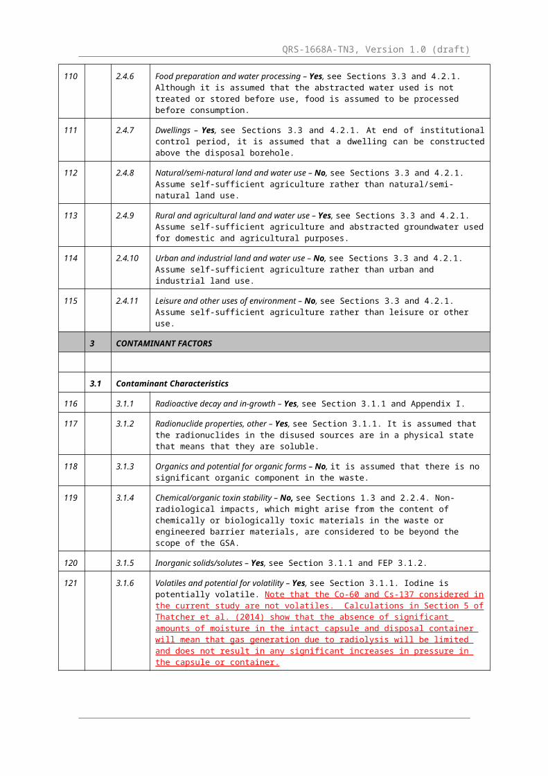
110 2.4.6 Food preparation and water processing – Yes, see Sections 3.3 and 4.2.1. Although it is assumed that the abstracted water used is not treated or stored before use, food is assumed to be processed before consumption.
111 2.4.7 Dwellings – Yes, see Sections 3.3 and 4.2.1. At end of institutional control period, it is assumed that a dwelling can be constructed above the disposal borehole.
112 2.4.8 Natural/semi-natural land and water use – No, see Sections 3.3 and 4.2.1. Assume self-sufficient agriculture rather than natural/semi-natural land use.
113 2.4.9 Rural and agricultural land and water use – Yes, see Sections 3.3 and 4.2.1. Assume self-sufficient agriculture and abstracted groundwater used for domestic and agricultural purposes.
114 2.4.10 Urban and industrial land and water use – No, see Sections 3.3 and 4.2.1. Assume self-sufficient agriculture rather than urban and industrial land use.
115 2.4.11 Leisure and other uses of environment – No, see Sections 3.3 and 4.2.1. Assume self-sufficient agriculture rather than leisure or other use.
3 CONTAMINANT FACTORS
3.1 Contaminant Characteristics
116 3.1.1 Radioactive decay and in-growth – Yes, see Section 3.1.1 and Appendix I.
117 3.1.2 Radionuclide properties, other – Yes, see Section 3.1.1. It is assumed that the radionuclides in the disused sources are in a physical state that means that they are soluble.
118 3.1.3 Organics and potential for organic forms – No, it is assumed that there is no significant organic component in the waste.
119 3.1.4 Chemical/organic toxin stability – No, see Sections 1.3 and 2.2.4. Non-radiological impacts, which might arise from the content of chemically or biologically toxic materials in the waste or engineered barrier materials, are considered to be beyond the scope of the GSA.
120 3.1.5 Inorganic solids/solutes – Yes, see Section 3.1.1 and FEP 3.1.2.

QRS-1668A-TN3, Version 1.0 (draft)
121 3.1.6 Volatiles and potential for volatility – Yes, see Section 3.1.1. Iodine is potentially volatile. Note that the Co-60 and Cs-137 considered in the current study are not volatiles. Calculations in Section 5 of Thatcher et al. (2014) show that the absence of significant amounts of moisture in the intact capsule and disposal container will mean that gas generation due to radiolysis will be limited and does not result in any significant increases in pressure in the capsule or container.
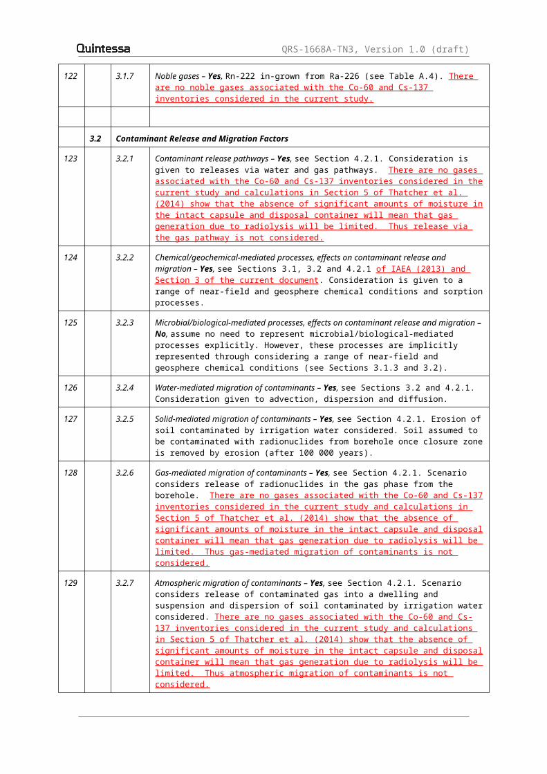
122 3.1.7 Noble gases – Yes, Rn-222 in-grown from Ra-226 (see Table A.4). There are no noble gases associated with the Co-60 and Cs-137 inventories considered in the current study.
3.2 Contaminant Release and Migration Factors
123 3.2.1 Contaminant release pathways – Yes, see Section 4.2.1. Consideration is given to releases via water and gas pathways. There are no gases associated with the Co-60 and Cs-137 inventories considered in the current study and calculations in Section 5 of Thatcher et al. (2014) show that the absence of significant amounts of moisture in the intact capsule and disposal container will mean that gas generation due to radiolysis will be limited. Thus release via the gas pathway is not considered.
124 3.2.2 Chemical/geochemical-mediated processes, effects on contaminant release and migration – Yes, see Sections 3.1, 3.2 and 4.2.1 of IAEA (2013) and Section 3 of the current document . Consideration is given to a range of near-field and geosphere chemical conditions and sorption processes.
125 3.2.3 Microbial/biological-mediated processes, effects on contaminant release and migration – No, assume no need to represent microbial/biological-mediated processes explicitly. However, these processes are implicitly represented through considering a range of near-field and geosphere chemical conditions (see Sections 3.1.3 and 3.2).
126 3.2.4 Water-mediated migration of contaminants – Yes, see Sections 3.2 and 4.2.1. Consideration given to advection, dispersion and diffusion.
127 3.2.5 Solid-mediated migration of contaminants – Yes, see Section 4.2.1. Erosion of soil contaminated by irrigation water considered. Soil assumed to be contaminated with radionuclides from borehole once closure zone is removed by erosion (after 100 000 years).
128 3.2.6 Gas-mediated migration of contaminants – Yes, see Section 4.2.1. Scenario considers release of radionuclides in the gas phase from the borehole. There are no gases associated with the Co-60 and Cs-137 inventories considered in the current study and calculations in Section 5 of Thatcher et al. (2014) show that the absence of significant amounts of moisture in the intact capsule and disposal container will mean that gas generation due to radiolysis will be limited. Thus gas-mediated migration of contaminants is not considered.
129 3.2.7 Atmospheric migration of contaminants – Yes, see Section 4.2.1. Scenario considers release of contaminated gas into a dwelling and suspension and dispersion of soil contaminated by irrigation water considered. There are no gases associated with the Co-60 and Cs-137 inventories considered in the current study and calculations in Section 5 of Thatcher et al. (2014) show that the absence of significant amounts of moisture in the intact capsule and disposal container will mean that gas generation due to radiolysis will be limited. Thus atmospheric migration of contaminants is not considered.
130 3.2.8 Animal, plant and microbe mediated migration of contaminants – Yes, see Section 4.2.1. Irrigation of crops and watering of animals considered.
131 3.2.9 Colloids mediated migration of contaminant – No. Assume that in systems with a cement grout near field, colloids are not readily formed due to the chemical conditions.

QRS-1668A-TN3, Version 1.0 (draft)
3.3 Exposure Factors
132 3.3.1 Food chains, uptake of contaminants in – Yes, see Sections 3.3 and 4.2.1. Ingestion of contaminated crops and animal produce considered.
133 3.3.2 Drinking water, foodstuffs and drugs, contaminant concentrations in – Yes, see Sections 3.3 and 4.2.1. Scenario includes consideration of the consumption of contaminated drinking water, crops and animal produce and inhalation of contaminated gas.
134 3.3.3 Environmental media, contaminant concentrations in – Yes, see Section 4.2.1. Need to consider contaminant concentrations in soil, air, crops and animals.
135 3.3.4 Non-food products, contaminant concentrations in – No, see Sections 3.3 and 4.2.1. Humans are assumed not to be exposed via non-food products for the scenario.
136 3.3.5 Exposure modes – Yes, see Sections 3.3 and 4.2.1. Scenario includes consideration of ingestion, inhalation and external irradiation.
137 3.3.6 Dosimetry – Yes, see Sections 2.4 and 2.5. Consider annual individual effective dose to an average adult member of a hypothetical critical group.
138 3.3.7 Radiological toxicity/effects – Yes, see Sections 2.4 and 2.5. Consider annual individual effective dose to an average adult member of a hypothetical critical group.
139 3.3.8 Chemical toxicity/effects – No, see Sections 1.3 and 2.2.4. Non-radiological impacts, which might arise from the content of chemically or biologically toxic materials in the waste or engineered barrier materials, are considered to be beyond the scope of the GSA.
140 3.3.9 Radon and radon daughter exposure – Yes, see Section 4.2.1. Rn-222 in-grows from Ra-226. No radon from the Co-60 and Cs-137 inventories are considered in the current study.

QRS-1668A-TN3, Version 1.0 (draft)
3 Screening of the Detailed Near-field FEP List from the GSA
The detailed near-field FEP list given in Appendix V of IAEA (2013) and the associated supporting text is reproduced below with additions to the text resulting from the consideration of Category 1 and 2 sources identified using underlining and red font. Unless stated otherwise, the references to section, appendix, box, table and figure numbers in the text relate to the sections, appendices, boxes, tables and figures in IAEA (2013).
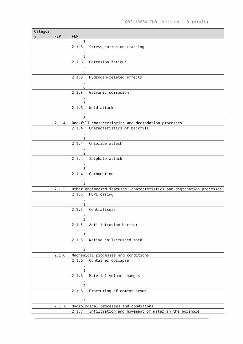
Table 3.2: GSA Detailed Near-field FEP List
Category FEP FEP2.1 Waste, Waste Form & Engineered Features
2.1.1 Waste inventory2.1.1.1 Radionuclide content2.1.1.2 Chemical content
2.1.2 Source characteristics and degradation processes2.1.2.1 Characteristics of sources2.1.2.2 Degradation of metallic sources2.1.2.3 Degradation of ceramic and glass sources2.1.2.4 Degradation of powder sources2.1.2.5 Degradation of gas and liquid sources
2.1.3 Container characteristics and degradation/failure processes2.1.3.1 Characteristics of containers2.1.3.2 General corrosion2.1.3.3 Localized corrosion2.1.3.4 Stress corrosion cracking2.1.3.5 Corrosion fatigue2.1.3.6 Hydrogen-related effects2.1.3.7 Galvanic corrosion2.1.3.8 Weld attack
2.1.4 Backfill characteristics and degradation processes2.1.4.1 Characteristics of backfill2.1.4.2 Chloride attack2.1.4.3 Sulphate attack2.1.4.4 Carbonation
2.1.5 Other engineered features: characteristics and degradation processes2.1.5.1 HDPE casing2.1.5.2 Centralisers2.1.5.3 Anti-intrusion barrier2.1.5.4 Native soil/crushed rock
2.1.6 Mechanical processes and conditions2.1.6.1 Container collapse2.1.6.2 Material volume changes2.1.6.3 Fracturing of cement grout
2.1.7 Hydrological processes and conditions2.1.7.1 Infiltration and movement of water in the borehole2.1.7.2 Degree of saturation
QRS-1668A-TN3, Version 1.0 (draft)
Category FEP FEP
2.1.7.3 Resaturation of the borehole2.1.7.4 Gas mediated water flow2.1.7.5 Coupled hydraulic processes including temperature, chemical or
electrical gradients2.1.8 Chemical processes and conditions
2.1.8.1 pH conditions2.1.8.2 Redox conditions2.1.8.3 Chloride and sulphate conditions2.1.8.4 Mineralization change2.1.8.5 Effects of chelating agents2.1.8.6 Colloid formation2.1.8.7 Precipitation/dissolution reactions (solubility limitation)
2.1.9 Biological processes and conditions2.1.9.1 Microbial growth and poisoning2.1.9.2 Microbially/biologically mediated processes2.1.9.3 Microbial/biological effects of evolution of redox and pH
2.1.10 Thermal processes and conditions2.1.10.
1Radiogenic, chemical and biological heat production from the wastes
2.1.10.2
Chemical heat production from engineered features
2.1.10.3
Temperature evolution
2.1.10.4
Temperature dependence of processes
2.1.11 Radiation effects2.1.11.
1Effects on containers
2.1.11.2
Effects on cement grout
2.1.11.3
Effects on other engineered features
2.1.11.4
Effects on pH
2.1.11.5
Effects on redox
2.1.11.6
Decay product gas generation
2.1.12 Gas sources and effects2.1.13 Extraneous materials
2.1 Waste, Waste Form & Engineered Features
2.1.1 Waste inventory
2.1.1.1 Radionuclide content
Description
Mass of radioactive material disposed in the borehole.Treatment in GSA
Unit inventory of 1 TBq per waste package is assumed for each of the 12 radionuclides that are in bold font in Table 3. The change in radionuclide
QRS-1668A-TN3, Version 1.0 (draft)
inventories due to radioactive decay and ingrowth after disposal is taken into account. For the high activity sources considered in the current study, an inventory of up to 350 TBq (130 kCi) of Co-60 per capsule and up to 470 TBq (30 kCi) of Cs-137 per capsule is assumed (see Section 5.2 of Little and Thatcher (2014)). Inclusion of FEP
Included in all scenarios.

QRS-1668A-TN3, Version 1.0 (draft)
2.1.1.2 Chemical content
Description
Mass of non-radioactive material disposed in the borehole. Treatment in GSA
Chemical contaminants are not considered in the GSA since non-radiological impacts, which might arise from the content of chemically or biologically toxic materials in the disused sources are beyond the scope of the GSA (see Section 1.3 and 2.4). Inclusion of FEP
Excluded in all scenarios.

QRS-1668A-TN3, Version 1.0 (draft)
2.1.2 Source characteristics and degradation processes
2.1.2.1 Characteristics of sources
Description
The physical and chemical characteristics of the disused sources at the time of disposal and evolution of these properties with time. This includes processes that are relevant specifically as sources degradation processes, rather than processes that contribute to the general evolution of the borehole.Treatment in the GSA
Table 12 summarises the characteristics of the sources considered in the GSA. A range of different physical and chemical forms is considered including metallic, ceramic, glass, powder, gas and liquid. The high activity Co-60 and Cs-137 sources considered the current study are assumed to come from industrial irradiators used for sterilisation/food preservation. The sources are usually doubly encapsulated in a stainless steel outer capsule that is typically 11 mm in diameter and 450 mm in length (IAEA, 2007), although no credit is been in this study to the isolation provided by the double encapsulation (it is conservatively assumed to have failed by the time that the capsule has failed). The Co-60 sources are typically metal pellets, while the Cs-137 sources are typically caesium chloride salt. Inclusion of FEP
Included in all scenarios.
2.1.2.2 Degradation of metallic sources
Description
Some of the sources considered in the GSA can occur in metallic form (e.g. Co-60, see Table 12). The metal will corrode with time resulting in the release of radionuclides into water and the generation of hydrogen gas. Treatment in the GSA
Degradation of the metallic sources is assumed to occur once the capsule containing the source and the failed source container is breached, allowing the entry of water and its contact with the source. Degradation occurs through various corrosion processes (see FEP 2.1.3) resulting in the release of radionuclides into water. It is considered that the amount of hydrogen gas generated is small in comparison to that generated by the corrosion of the capsule and disposal container.The high initial temperature (up to 275 °C) experienced by the Co-60 metallic sources (see Section 3 of Thatcher et al. (2014)) will promote some
QRS-1668A-TN3, Version 1.0 (draft)
degradation of the source prior to the breach of the capsule due to the various corrosion processes discussed under FEP 2.1.3. However, the extent of this early degradation will be limited due to the relatively short period of elevated temperatures (less than 30 years, see Section 3 of Thatcher et al. (2014)) and the limited supply of water vapour in the sealed capsule. Similarly, degradation promoted by nitric acid formation resulting from radiolysis in the sealed capsule is expected to be limited (see Section 5.1 of Thatcher et al. (2014)). Inclusion of FEP
Included in all scenarios.
2.1.2.3 Degradation of ceramic and glass sources
Description
Some of the sources considered in the GSA can occur in ceramic or glass form (e.g. Sr-90, see Table 12). The ceramic/glass will dissolve with time resulting in the release of radionuclides into water.Treatment in the GSA
Dissolution of the ceramic/glass sources is assumed to occur once the capsule containing the source and the failed source container is breached, allowing the entry of water and its contact with the source. The rate of dissolution will be affected by the geochemical conditions in the borehole. Inclusion of FEP
Included in all scenarios, although not relevant for the high activity inventories of Co - 60 and Cs - 137 considered in the current study.

QRS-1668A-TN3, Version 1.0 (draft)
2.1.2.4 Degradation of powder sources
Description
Some of the sources considered in the GSA can occur as powders (e.g. Cs-137 and Ra-226, see Table 12). Indeed, the high activity Cs-137 sources considered in the current study are assumed to be caesium chloride powder. The powder will dissolve with time resulting in the release of radionuclides into water. For soluble powders (e.g. Cs - 137 and Ra-226), the dissolution will be instantaneous on contact with water. Treatment in the GSA
Dissolution of the powder sources is assumed to occur once the capsule containing the source and the failed source container is breached, allowing the entry of water and its contact with the source. The GSA takes account of the solubility of the powder under the various geochemical conditions assessed. Inclusion of FEP
Included in all scenarios.
2.1.2.5 Degradation of gas and liquid sources
Description
Some of the sources considered in the GSA can occur as gas (e.g. H-3 and Kr-85, see Table 12) and liquid (e.g. H-3, see Table 12). Treatment in the GSA
No degradation of the gas and liquid is assumed to occur other than radioactive decay (see FEP 3.1.1). Once the capsule containing the source and the failed source container is breached, it is assumed that the gas and liquid are released immediately. The high activity sources considered in the current study do not contain gas or liquid. Inclusion of FEP Excluded in all scenarios (other than radioactive decay - see FEP 3.1.1).
2.1.3 Container characteristics and degradation/failure processes
2.1.3.1 Characteristics of containers
Description
The characteristics of the various containers in which the disused sources are enclosed. Treatment in the GSA

QRS-1668A-TN3, Version 1.0 (draft)
Three “containers” are identified in Section 3.1.2 for use in the borehole disposal concept.
The source container within which the source material is sealed. It is conservatively assumed that the source container will have failed prior to disposal and so no credit is taken for it.
The Type 304 stainless steel capsule containing the source container. For the Category 1 and 2 sources, the capsule will be Type 316L stainless steel. Until breached, it isolates source container from water, animals and humans and prevents escape of gas from source container. Once breached, it limits fraction of radionuclides available for release from the capsule until the entire capsule has been corroded.
The Type 316 L stainless steel disposal container, which contains the capsule and containment barrier. Until breached, it isolates source container, capsule and containment barrier from water, animals and humans. Once it and the capsule are both breached, the disposal container can limit the fraction of radionuclides available for release into the borehole until the entire container has been corroded.
For the Design Scenario, it is assumed that none of the closure welds on the capsule and disposal container are defective. For Defect Scenario D1, it is assumed that the closure weld in one 316 L disposal container is defective. For Defect Scenario D2, it is assumed that the closure weld in one 304 capsule is defective. For Defect Scenario D4, it is assumed that the closure weld in one 316 L disposal container and one 304 capsule and the faulty capsule is in the faulty container.Inclusion of FEP Capsule and disposal container included in all scenarios. Source container excluded from all scenarios.
2.1.3.2 General corrosion
Description
Stainless steels are subject to general corrosion at a rate that varies with time, temperature, redox conditions, pH, and salinity. Stainless steels are protected by the formation of a stable Cr(III) oxide or hydroxide film (variously represented by Cr2O3, Cr(OH)3, or CrOOH).On freshly polished surfaces, the corrosion rate will continue to decrease with time for several years after exposure to the corrosive environment as the passive film develops. The film is typically amorphous, although for

QRS-1668A-TN3, Version 1.0 (draft)
some passive materials re-crystallisation of the oxide can occur over time, resulting in an increase in corrosion rate.The general corrosion rate of stainless steel is typically not a strong function of the redox potential, here interpreted in terms of the corresponding dissolved O2 concentration. Increasing [O2] leads to an increase in ECORR, but provided the potential is within the passive range the corrosion rate is determined more by the properties of the oxide film than by the rate of the cathodic reaction (the reduction of O2). An increase in ECORR, however, will result in an increase in the potential drop across the passive film and the “leakage current” (which corresponds to the rate of general corrosion) will increase accordingly. In contrast, the corrosion rate of active materials may be proportional to the [O2] if the rate of corrosion is cathodically limited.The protectiveness of the passive film depends on the solution pH. The minimum solubility of Cr(III) oxides lies between pH 7 and pH 8.5, depending upon the stable form. The solubility increases at both lower and higher pH, although the rate of increase in solubility is much greater in acidic solutions. Furthermore, the stability of the oxides of other alloying elements at higher pH maintains a stable passive film in the alkaline range.Chloride ions tend to de-stabilise the passive film on stainless steels. Although the effect of Cl- is most significant for the initiation and propagation of localised corrosion, Cl- ions also tend to decrease the stability of the passive oxide film and lead to an increase in general corrosion rate.Treatment in the GSA
General corrosion of the stainless steel capsule and disposal container is one of the main corrosion processes included in the GSA. The corrosion rate is taken to be a function of redox potential, pH, and Cl- concentration (see FEP 2.1.8).Isothermal conditions are assumed for Category 3 to 5 sources, so the temperature dependence of the general corrosion rate is not considered (see FEP 2.1.10.4). It is assumed that the general corrosion rate attains a steady state soon after emplacement of the waste and does not change with time other than due to the evolution of porewater pH with time. For Category 1 and 2 sources, calculations in Section 3 of Thatcher et al. (2014) show that isothermal conditions do not initially exist in the borehole for the highest activity sources. Isothermal conditions are established after around 50 years for the Co-60 sources and 200 years for the Cs-137 sources. Therefore some increase in general corrosion rates might be expected to occur at least for the initial period of raised temperatures. Radiolysis effects from Category 1 and 2 sources can also be expected to have some, albeit limited, impact on the general corrosion of the capsule

QRS-1668A-TN3, Version 1.0 (draft)
and disposal container due to the potential formation of nitric acid and other reactive hydrolytic products (Section 5, Thatcher et al. 2014). Shoesmith and King (1999) have reviewed the evidence for the effects of - radiation on the corrosion of various metallic materials. For stainless steels, no acceleration of general corrosion was reported at an absorbed dose rate of 10 4 Gy/hr (1 Mrad/hr) which is around the maximum dose rate calculated in Section 5 of Thatcher et al. (2014) for the capsule and around an order of magnitude greater than that for the disposal container. Cautiously assuming an order of magnitude increase in the highest general corrosion rates given in Table 50 of IAEA (2013) and the fastest cement degradation times given in Table 38 of IAEA (2013) due to temperature and radiolysis effects gives a capsule failure time of around 3000 years for the high activity sources considered in the current study. Over this timescale the inventory of Co-60 and Cs-137 will have decayed to be effectively zero and so failure of the capsule will have no impacts. Furthermore, as shown in Section 3 of Thatcher et al. (2014), the conditions of increased temperature will be maintained for only around 50 years for the Co-60 sources and 200 years for the Cs - 137 sources. Therefore assuming increased general corrosion rates over a 3000 year period is highly conservative. Given the localised impact of the temperature increase in the borehole (typically less than 0.2 m, see Section 3 of Thatcher et al. (2014)), the impact on the general corrosion rate of vertically adjacent disposal containers and capsules that might container longer live radionuclides can be expected to be limited. Inclusion of FEP Included in all scenarios.2.1.3.3 Localised corrosion
Description
Localised corrosion of stainless steels can take the form of discrete pitting of exposed surfaces or of crevice corrosion in geometrically occluded regions or under surface deposits. Localised attack is favoured by higher temperatures, lower pH, increased Cl- concentrations, and more-positive ECORR (or EH) values. A number of oxyanions, including SO42-, inhibit the aggressive effect of Cl-.The initiation of localised corrosion occurs if the corrosion potential ECORR
exceeds the breakdown potential of the passive film. Crevice corrosion tends initiate more easily than pitting as the occluded region serves to both concentrate aggressive ions (such as Cl-) and also create a differential O2
concentration cell, leading to the spatial separation of anodic and cathodic reactions and the resulting localised attack. Once initiated, a pit or crevice

QRS-1668A-TN3, Version 1.0 (draft)
will continue to propagate until some process leads to the loss of the critical pit or crevice chemistry and the cessation of corrosion. The rate of propagation of localised corrosion can be several orders of magnitude higher than the rate of general corrosion.Type 316L stainless steel is more resistant to localised corrosion than Type 304 because of the addition of Mo. Molybdenum provides stability at low pH because of the formation of MoO2 or MoO3 phases which are stable in acidic solutions. Type 304 stainless steel can also become sensitised during welding because of the formation of chromium carbides at grain boundaries, leading to an increased susceptibility to intergranular SCC.Once initiated, a crevice (as assumed here) will propagate through the wall thickness until perforation of the shell occurs at a particular location within the crevice. Following initial perforation, the area of through-wall corrosion will extend over the entire creviced region (provided the through-wall penetration does not result in the loss of the critical crevice chemistry) and may extend beyond the area of the original occluded region if precipitated corrosion product acts as its own crevice former. Adjacent creviced regions may coalesce to produce larger defects in the container, although the rate of crevice propagation will slow with time as the cathode:anode surface area ratio diminishes as more of the container wall is corroded.In general, the susceptibility to initiation and the severity of propagation increase with increasing electrochemical potential (E), temperature (T), and [Cl - ] and decreasing pH. Figure 28 of IAEA (2013) shows the dependence of the pitting potential on T and [Cl - ]. The pitting potential moves to more “active”, i.e., more negative, values with increasing T and [Cl - ]. Figure 31 of IAEA (2013) shows the pitting potential decreases with increasing temperature, accounting for the increased susceptibility of these alloys at elevated temperature and that the potential for Type 316 exhibits a plateau at temperatures above ~70 °C. Shoesmith and King (1999) note that radiation has been found to inhibit pitting, probably due to the annealing of defects in the oxide film. There is some evidence for enhanced initiation of crevice corrosion at a dose rate of 2.8 Gy/hr, although higher dose rates appear necessary to sustain crevice propagation. Treatment in the GSA
Localised corrosion is included in the GSA corrosion assessment as a failure mechanism for the stainless steel waste capsule and disposal container.Neither grade of stainless steel is deemed to be susceptibility to pitting or crevice corrosion during Stage 1 or 2 of cement grout degradation because of the high pH of the cement grout porewater contacting the capsule and disposal container. This conclusion is based on a comparison of reported

QRS-1668A-TN3, Version 1.0 (draft)
ECORR and breakdown potentials measured at high pH. During Stages 3 and 4, both materials may be susceptible to localised corrosion in aerated groundwaters (in which ECORR exceeds the repassivation potential for crevice corrosion) but not in anaerobic (reducing) waters. The concentration of Cl - is sufficient to induce localised corrosion even in the fresh groundwaters considered in the GSA.The conditions of potential, Cl- concentration, and pH for the initiation of localised corrosion have been converted to an equivalent pH value. In this way, the time at which localised corrosion is possible can be estimated from the time-dependence of the cement grout porewater pH.To maintain conservatism, the potential at which localised corrosion initiates is taken to be 200 mV more negative than the re-passivation potential for crevice corrosion. The conservatism in this treatment arises from three factors (i) the choice of crevice corrosion rather than pitting (pitting occurs at more positive potential), (ii) the selection of the re-passivation potential as the criterion for initiation, and (iii) the use of a value 200 mV more negative than that reported to account for the stochastic nature of re-passivation potentials.Based on this approach, the equivalent pH values for the initiation of localised corrosion for Types 304 and 316L stainless steel are taken to be pH 11 and pH 10 (or the background pH of the groundwater for alkaline waters). The higher pH value for Type 304 stainless steel reflects the greater susceptibility of this material to localised corrosion and the possibility of sensitisation of the capsule closure weld.Crevice propagation is not explicitly treated in the GSA corrosion analysis as the rate of corrosion is relatively fast compared with the predicted container lifetimes. Based on reported crevice propagation rates, through-wall perforation will occur within a few years of initiation. Growth of the perforation (and of adjacent perforations) will occur at a similar rate, possibly leading to through-wall perforation on most of the container surface within a period of, say, 100 years. This period is short compared with the estimated lifetimes of >104 years. Therefore, no credit is taken for the remaining mass-transfer resistance offered by the capsule and disposal container for the period between the initiation of localised corrosion and such extensive localised attack that the vessel no longer restricts mass transport into or out of the failed container.For the BDC, the aggressive effects of Cl- ions and elevated temperature are offset by the alkaline pH. It is typically found that a critical [OH-]:[Cl-] ratio (i.e., a critical pH:[Cl-] ratio) exists, above which localised corrosion does not occur (or, at least, is unlikely). However, this critical ratio increases with increasing temperature.

QRS-1668A-TN3, Version 1.0 (draft)
For the high activity sources considered in the current study, surface temperatures higher than the local boiling point will lead to the formation of progressively concentrated and more corrosive electrolyte solutions near to solid surfaces, leading to the precipitation of soluble salts there. The composition of these salts will depend upon the initial composition of the water, but may include chlorides, sulphate and carbonates. Based on the near-field temperatures calculated in Section 3 of Thatcher et al. (2014), the surface of the containers will become dry for a period, during which no aqueous corrosion will occur. However, as the temperature cools moisture will condense on the surface and the salts precipitated previously may re-dissolve. Then, there will be a period of time when the corrosive environment could be aggressive and promote localised corrosion under oxidising conditions. Such processes would affect the outside of the disposal container and also the inside. The moisture for external localised corrosion would be derived from the surrounding geosphere, while the moisture for the internal localised corrosion would be derived from any free water (and potentially bound water) in the cement containment barrier. However, the hydraulic evolution inside the disposal container is likely to be very strongly controlled by the amount of water available for vaporisation and the relative volume of voidage (e.g. unfilled porosity) inside the container. For example, the presence of large amounts of free water could cause a very large rise in pressures inside the container and cause a breach, while simultaneously retaining significant quantities of liquid water inside the disposal container. Alternatively, if the porosity is large in comparison with the amount of vaporised water, it is likely that nearly all the available water will be vaporised leaving little liquid water, but retaining the integrity of the disposal container.Given that peak dose rates of around 10 4 Gy/hr might occur for the high activity sources considered in the current study (see Section 5 of Thatcher et al. (2014)), the - radiation might be a further factor that results in enhanced local corrosion given that it can promote the formation of oxidising conditions local to the capsule and disposal container.Inclusion of FEP Included in all scenarios.

QRS-1668A-TN3, Version 1.0 (draft)
2.1.3.4 Stress corrosion cracking
Description
Stress corrosion cracking (SCC) of stainless steels is known to occur in chloride solutions. Cracking results from the presence of an applied tensile stress or from residual stress in welds that have not undergone a stress-relief treatment.Cracks typically initiate from pits and propagate relatively rapidly in a direction normal to the principal tensile stress.From an environmental viewpoint, the conditions that support cracking are more severe than those that produce pitting of the exposed surface. Therefore, pitting and crevice corrosion occur at more-negative potentials, lower Cl- temperatures, and/or lower temperatures than those at which cracking is observed. Treatment in the GSA
For the disposal of Category 3 to 5 sources, SCC is not included as a failure mechanism in the GSA corrosion analysis. The initiation (and relatively rapid propagation) of crevice corrosion is considered to occur under less aggressive conditions than cracking (see FEP 2.1.3.3). Given that crevice propagation is rapid, failure of the container will occur via this mechanism before failure by SCC.For disposal containers and capsules containing Category 1 and 2 sources, the elevated temperature conditions will result in increased tensile stress which could promote SCC and so consideration needs to be given to SCC as well as localised corrosion .Inclusion of FEP Excluded for Category 3 to 5 sources in all scenarios. Included for Category 1 and 2 sources.
2.1.3.5 Corrosion fatigue
Description
Corrosion fatigue is a result of the action of a corrosive environment and a cyclic load resulting in cracking. The corrosion component enhances the crack growth rate that would otherwise be observed in the absence of the environment (i.e., pure fatigue).Treatment in the GSA
Corrosion fatigue is not included as a failure mechanism in the GSA corrosion analysis because of the absence of cyclic loading of the capsule or

QRS-1668A-TN3, Version 1.0 (draft)
disposal container for the disposal of all sources, including Category 1 and 2 sources.Inclusion of FEP Excluded in all scenarios.
2.1.3.6 Hydrogen-related effects
Description
Many metals are susceptible to failure due to the absorption of atomic hydrogen. Failure often takes the form of cracks or blisters due to the accumulation of atomic or molecular hydrogen at defects in the material. Ferritic steels are particular susceptible to hydrogen effects because of the high diffusivity of hydrogen. The susceptibility to hydrogen damage generally increases with increasing strength of the material because the higher potential stress gradients that can be created cause greater segregation of absorbed hydrogen.Austenitic stainless steels (such as Types 304 and 316L) are generally less susceptible to hydrogen effects than ferritic materials (e.g., carbon or mild steels) because the diffusivity of hydrogen in the austenite phase is several orders of magnitude lower than in the ferrite phase.Treatment in the GSA
Hydrogen-related degradation mechanisms are not included in the corrosion analysis for the GSA because of the generally lower susceptibility of austenitic stainless steels to hydrogen effects.Inclusion of FEP Excluded in all scenarios.
2.1.3.7 Galvanic corrosion
Description
Galvanic corrosion occurs when two metals are coupled together in a conductive medium. One of the metals acts as the anode and corrodes faster than if it was not coupled, and the other metal becomes the cathode and corrodes more slowly. The severity of galvanic corrosion depends on the separation of the two metals (in terms of mV) in the so-called galvanic series, the relative surface areas of the materials, and the conductivity of the electrolyte.Treatment in the GSA

QRS-1668A-TN3, Version 1.0 (draft)
Galvanic corrosion is not included in the corrosion analysis for the GSA because of the apparent absence of dissimilar metal contacts for either the capsule or the disposal container.Inclusion of FEP Excluded in all scenarios.
2.1.3.8 Weld attack
Description
Welds are often locations for preferential corrosion. The enhanced susceptibility of welds results from (i) micro-scale galvanic cells that can be created due to the use of a dissimilar weld material (ii) microstructural differences between the weld metal, heat-affected zone, and base metal, or (iii) segregation of certain alloying elements to grain boundaries (sensitisation).Stainless steels can be susceptible to preferential weld attack if steps are not taken to avoid the effects listed above. Type 304 stainless steel is susceptible to intergranular attack or enhanced SCC due to sensitisation of grain boundaries.Treatment in the GSA
The possibility of enhanced susceptibility of sensitised welds for the Type 304 capsule is implicitly included in the GSA corrosion analysis through the use of a higher pH threshold for the initiation of localised corrosion.Inclusion of FEP Implicit in enhanced susceptibility of Type 304 capsules to the initiation of localised corrosion assumed for all scenarios.

QRS-1668A-TN3, Version 1.0 (draft)
2.1.4 Backfill characteristics and degradation processes
2.1.4.1 Characteristics of backfill
Description
Chemical and physical characteristics of the backfill used in the borehole disposal concept. Treatment in the GSA
Cement “backfill” is used as a chemical and physical barrier in five locations in the borehole disposal concept (see Section 3.1.2):
the containment barrier – the space between the capsule and the disposal container is backfilled with cement grout;
the disposal zone backfill - cement grout is used to separate disposal containers in vertical dimension from one another, and in the horizontal dimension from the borehole casing;
the disposal zone plug at base of borehole; the disturbed zone backfill - cement grout is used to fill the gap
between the casing and the host rock and any voids/cracks in the host rock immediately adjacent to the borehole; and
the closure zone backfill – it is assumed that the first 5 m from the ground surface is native soil/crushed rock and the remainder down to the disposal zone is cement grout.
For all scenarios other than Defect Scenario D3, it is assumed that cement grout emplaced under appropriate QA/QC is present in all five locations. For Defect Scenario D3, it is assumed that the cement grout in the disposal and disturbed zone has not been emplaced under appropriate QA/QC and so degrades more rapidly.Inclusion of FEP Included in all scenarios.

QRS-1668A-TN3, Version 1.0 (draft)
2.1.4.2 Chloride attack
Description
The effect of chloride ions in groundwater coming into the borehole on the cement grout backfill used in the borehole (e.g. Nielsen et al. 2005). Chloride will to some extent become bound to solid phases as a consequence of reactions within the cement grout. Some chloride will form solid compounds such as Friedel salts (Ca3Al2O6.CaCl2.10H2O) while some chloride will sorb to the surfaces of calcium silicate hydrates (CSH). However, the extent to which this binding occurs will depend upon the concentrations and characteristics of other constituents within the pore fluid. Notably carbonate and sulphate will generally act to diminish the binding of chloride. The chemical composition of the cement grout is also a significant control. In reality this process would have less effect on the strength and pH-buffering capacity of the cement grout barrier than would attack by sulphate and/or carbonate. Furthermore, it would reduce the availability of chloride ions for corrosion. Treatment in the GSA
Chloride attack of the cement grout is not taken into account explicitly. Instead illustrative calculations are undertaken in which the capacity for chemical buffering capacity and ability to physically retard fluid flow is diminished in comparison with the reference case. These calculations are designed to illustrate the possible significance of attack not only by chloride, but also by sulphate and carbonate. Additionally, from the perspective corrosion, it is conservative to assume that the concentrations of chloride in the porewater contacting the steel barriers would not be diminished by reactions in the cement grout.Inclusion of FEP Included in all scenarios.
2.1.4.3 Sulphate attack
Description

QRS-1668A-TN3, Version 1.0 (draft)
The effect of sulphate ions in groundwater coming into the borehole on the cement grout backfill used in the borehole. These ions diffusing into cements react with certain phases forming larger volume products. Initially, this volume increase will reduce the interconnected porosity and hence the permeability. However, once the volume increase has proceeded to the extent that it cannot be accommodated by the porosity, there will be an overall internal expansion eventually causes stress, cracking and exfoliation of the reacted zone (Francis et al. 1997). The range of reactions involved is complex and depends on the conditions, particularly the concentration of sulphate. Ettringite and gypsum are among the products. The attack depletes the reservoir of alkalinity (calcium hydroxide) in the concrete. An overall effect of this is to reduce the capacity of cementitious backfill to buffer pH to high values. Sulphate attack in certain cement compositions could be increased by radiolysis since sulphide (e.g. present in cement constituents) could be oxidized to sulphate by radiolytic oxidants (principally H2O2) (e.g. Utton and Godfrey, 2010).To predict the behaviour of the cement grout and the temporal evolution of the porewater chemistry would require the development of complex coupled models taking into account a complete physical and chemical description of the cement grout-porefluid system. The detailed evolution of this system will be case-specific.Treatment in the GSA
It is assumed that sulphate resistant cement grout is used (see Section 3.1.2). Nevertheless, sulphate attack will occur. However, it is not treated explicitly in the GSA. To do so would be unjustified in the absence of site-specific and engineered barrier-specific information (e.g. exact porewater composition, groundwater flow rate and cement grout composition) and without developing detailed coupled models. Instead illustrative calculations are undertaken in which the capacity for chemical buffering capacity and ability to physically retard fluid flow is diminished in comparison with the reference case. These calculations are designed to illustrate the possible significance of attack not only by sulphate, but also by chloride and carbonate. Inclusion of FEP Included in all scenarios.
2.1.4.4 Carbonation
Description
The effect of carbonate ions in groundwater coming into the borehole on the cement grout backfill used in the borehole. However, to predict the overall

QRS-1668A-TN3, Version 1.0 (draft)
influence of carbonate attack on the behaviour of the cement grout and the temporal evolution of the porewater chemistry would require the development of complex coupled models. Furthermore, these models would need to take into account a complete physical and chemical description of the cement grout-porefluid system. The detailed evolution of this system will be case-specific. The carbonate will tend to reduce the ability of concrete to impose a high pH on borehole water (Francis et al. 1997), by reacting with the main source of alkalinity, calcium hydroxide and by limiting access of the migrating porewater to reactive cementitious phases. On its own this effect on pH would be detrimental with respect to the longevity of the steel barriers. However, carbonation will also tend to seal the porosity which may decrease the porosity of the cement grout, at least at relatively early times. Thus, the flux of water past the steel barriers could be diminished, which would tend to enhance the longevity of these barriers. Furthermore, carbonation would reduce carbonates available for corrosion.Over the relevant temperature ranges, under fixed PCO2 conditions, carbonate phases are generally less soluble at higher temperatures (e.g., as calculated using the Geochemists Workbench database thermo.dat; Bethke, 2008) and so the increased initial temperatures, associated with the disposal of the high activity sources considered in the current study, could be expected to cause an increase in carbonation over the initial 50 to 200 years (for Co-60 and Cs-137 sources, respectively). Treatment in the GSA
Carbonation is not treated explicitly. To do so would be unjustified in the absence of site-specific and engineered barrier-specific information (e.g. exact porewater composition, groundwater flow rate and cement grout composition) and without developing detailed coupled models. Instead illustrative calculations are undertaken in which the capacity for the chemical buffering capacity and ability to physically retard fluid flow is diminished in comparison with the reference case. These calculations are designed to illustrate the possible significance of attack not only by carbonate, but also by chloride and sulphate. Inclusion of FEP Included in all scenarios.

QRS-1668A-TN3, Version 1.0 (draft)
2.1.5 Other engineered features: characteristics and degradation processes
2.1.5.1 HDPE casing
Description
High-density polyethylene (HDPE) casing emplaced at time of drilling to help ensure the borehole is dry during emplacement of the disposal containers. Top sections are withdrawn at closure of borehole down to 1 m of the disposal zone.Treatment in the GSA
HDPE is subject to various corrosion processes leading to a loss of mechanical integrity the rate of which will be increased by temperature and radiolysis effects. The leaching of plasticisers results in embrittlement of the plastic and eventual cracking and loss of structure. Some forms of HDPE are also susceptible to stress corrosion cracking. It wis conservatively assumed that HDPE casing fails immediately on closure of the borehole and so is not represented in the post-closure GSA calculations for all categories of sources. It is assumed that any binding between radionuclides and organic products of the breakdown of the HDPE would have an insignificant effect on radionuclide migration. Inclusion of FEP
Implicitly included in all scenarios since it is a component of the reference design. However it is not explicitly modelled in post-closure GSA calculations for all categories of sources. There is little information with which to judge whether or not organics released from the degradation of HDPE could complex with radionuclides to the extent that the mobility of radionuclides is affected significantly. However, IAEA (2006) notes that HDPE is being considered as a material for fabricating containers for some kinds of radioactive wastes. No mention is made of the possible significance of complexation between breakdown products and radionuclides. It is therefore assumed that the chemical effects of HDPE breakdown would be insignificant.

QRS-1668A-TN3, Version 1.0 (draft)
2.1.5.2 Centralisers
Description
The casing is fitted with centralisers to ensure that the casing is in the middle of the borehole. These centralisers are made of thin mild steel plates inserted vertically to ensure that they do not hamper the flow of the backfill slurry.Treatment in the GSA
The centralisers will be subject to similar corrosion processes as the capsules and disposal containers (see FEP 2.1.3). Since they are made of mild rather than stainless steel, corrosion will occur much faster. The centralisers perform no role as a barrier to radionuclide migration and so are not represented in the post-closure GSA calculations. Inclusion of FEP Implicitly included in all scenarios since they are a component of the reference design. However they are not explicitly modelled in post-closure GSA calculations.
2.1.5.3 Anti-intrusion barrier
Description
An anti-intrusion barrier (for example a metallic ‘drill deflector’) is placed above the disposal zone in order to deter/prevent human intrusion. Treatment in the GSA
The role of the barrier is to deter/prevent human intrusion. It is not considered to be a barrier to radionuclide migration by groundwater and gas pathways and so is not explicitly represented in the post-closure GSA calculations.Inclusion of FEP Implicitly included in all scenarios since it is a component of the reference design. However it is not explicitly modelled in post-closure GSA calculations.
2.1.5.4 Native soil/crushed rock
Description
Native soil/crushed rock used to fill the top 5 m of the closure zone.Treatment in the GSA
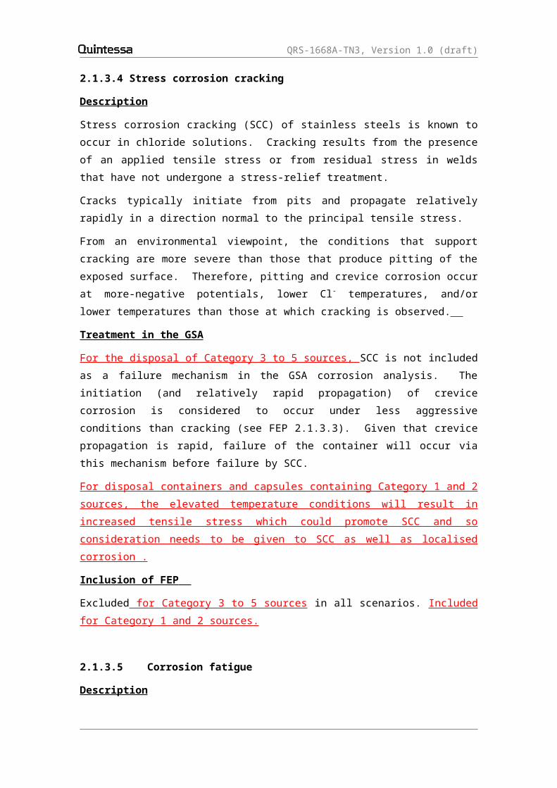
QRS-1668A-TN3, Version 1.0 (draft)
The role of the barrier is to deter/prevent human intrusion. It is not considered to be a barrier to radionuclide migration by groundwater and gas pathways and so is not explicitly represented in the post-closure GSA calculations Inclusion of FEP Implicitly included in all scenarios since it is a component of the reference design. However it is not explicitly modelled in post-closure GSA calculations.

QRS-1668A-TN3, Version 1.0 (draft)
2.1.6 Mechanical processes and conditions
2.1.6.1 Container collapse
Description
The processes that lead to the collapse of the containers in the post-closure period. Treatment in the GSA
As noted in FEP 2.1.3.1, there are three containers considered in the GSA (the source container, the capsule and the disposal container). The source container and the capsule have significant voidage, whereas the disposal container is backfilled with the cement grout that forms the containment barrier. Whilst the source container is assumed to have failed prior to closure, the capsule that contains it and its associated source is assumed to be intact, as is the disposal container. With the ingress of groundwater into the borehole, the disposal container will be subject to gradual corrosion which will eventually lead to the breach of the container (see FEP 2.1.3). Corrosion of the disposal container will not result in its collapse since it is backfilled with the cement grout containment barrier. Following ingress of water into the disposal container, the capsule will be subject to corrosion (see FEP 2.1.3). Corrosion will lead to breaches in the capsule. In addition, the cement grout containment barrier in the disposal container will be subject to expansive reaction with ions in the incoming groundwater, particularly sulphate (see FEP 2.1.4.3). Ultimately the combination of these processes might lead to the collapse of the capsule due to its significant voidage. However, the impact of this possible collapse is not considered to be significant in terms of increasing the release rate of radionuclides given that the capsule will have to be significantly corroded prior to collapse and so longer performing the role of a significant barrier. Inclusion of FEP Excluded in all scenarios.
2.1.6.2 Material volume changes
Description
The effects of volume changes in materials used in borehole. The volume changes associated the main materials used in the borehole are as follows:
cements can show volume increased due to their degradation (see FEP 2.1.4); and

QRS-1668A-TN3, Version 1.0 (draft)
corrosion of metal containers usually leads to corrosion products that have larger volumes than the original metals (see FEP 2.1.3).
Treatment in the GSA
It is considered that volume changes will not be significant in the borehole although they might promote some localised fracturing of the cement grout (see FEP 2.1.6.3). Inclusion of FEP Included implicitly in all scenarios through consideration of increase permeability of cement grout with time.2.1.6.3 Fracturing of cement grout
Description
Cement of the containment barrier and the backfill may fracture due to applied stresses (e.g. from material volume changes – see FEP 2.1.6.2) and/or degradation. The temperature gradient resulting from the disposal of the high activity sources considered under the current study, and any anisotropy in the local stress environment will also promote the fracturing of the containment barrier and the backfill cement.Treatment in the GSA
It is considered that fracturing of the cement grout in the borehole will occur due to volume changes and cement grout degradation, and, in the case of the high activity sources considered under the current study, the thermal gradient. This is implicitly considered through consideration of increase permeability of cement grout with time.Inclusion of FEP Included implicitly in all scenarios.

QRS-1668A-TN3, Version 1.0 (draft)
2.1.7 Hydrological processes and conditions
2.1.7.1 Infiltration and movement of water in the borehole
Description Water flow into and through the borehole is governed by the hydraulic gradient, hydraulic conductivity, porosity, and the degree of saturation in the borehole and, in the case of the borehole in the unsaturated zone, the percolation rate in the unsaturated zone. Treatment in the GSA
It is assumed that the infiltration rate into the borehole is time variant due to changes in the hydraulic conductivity and porosity of the cement grout in the borehole as a consequence of cement grout degradation. Thermal effects from Category 1 and 2 sources will also impact the initial water flow in and around the borehole. However, calculations in Section 3 of Thatcher et al. (2014) for the high activity Co-60 and Cs-137 sources considered in the current study show the thermal effects are limited in terms of their spatial and temporal impacts (less than a few hundred years and within 1 m of the borehole) and are unlikely to be present at the time of capsule failure.Inclusion of FEP
Included in all scenarios.
2.1.7.2 Degree of saturation
Description
The degree of saturation can affect the flow of water through the borehole (see FEP 2.1.7.1) and also the corrosion processes. Atmospheric corrosion typically exhibits a threshold relative humidity of 60-70% below which there is insufficient surface moisture to support electrochemical reactions (Shreir 1976). In aerated systems, the corrosion rate of non-passive materials is often determined by the rate of supply of O2. As a consequence, the corrosion rate can be higher in unsaturated systems as the rate of supply of O2 through the vapour phase is orders of magnitude higher than through aqueous solution.For passive materials such as Types 304 and 316L stainless steel, the corrosion behaviour is determined by the properties of the passive film. Corrosion is therefore anodically, rather than cathodically, limited and corrosion rates are similar in the vapour phase and in aqueous solutions, for equivalent chloride concentration and redox conditions.
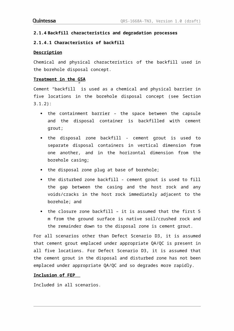
QRS-1668A-TN3, Version 1.0 (draft)
Thin moisture films, as formed on surfaces in humid atmospheres, can exhibit higher solute concentrations because of evaporative concentration mechanisms.Treatment in the GSA
The degree of saturation of the borehole is explicitly taken into account in the calculation of water flows in the GSA.The corrosion rate and susceptibility to localised corrosion is assumed to be the same for saturated and unsaturated sites. It is implicitly assumed that the relative humidity in the borehole will always exceed the threshold of 60-70% RH for corrosion processes.It is assumed that evaporative concentration of electrolytes in thin moisture films does not occur because of the absence of thermal gradients assumed for the GSA for Category 3 to 5 sources (see FEP 2.1.10). For the Category 1 and 2 sources considered in the current study, the thermal effects can result in initial temperatures in the borehole backfill being slightly in excess of 100 °C for certain disposal systems (see Section 3 of Thatcher et al. (2014)). However, temperatures rapidly decrease to less than 50 °C within 20 years and so the impact of raised temperatures on the degree of saturation in the borehole will be transient, especially in terms of the expected failure times of the capsule. Inclusion of FEP Included in all scenarios.
2.1.7.3 Resaturation of the borehole
Description At closure, the borehole will be unsaturated (be it in the unsaturated or saturated zone). With time, the borehole in the saturated zone will resaturate. The rate of resaturation will be dependent on the hydraulic and thermal conditions in the borehole and the surrounding geosphere, and the generate rate of gases and associate gas pressure. Treatment in the GSA
It is assumed that the borehole in the unsaturated zone remains unsaturated and the degree of saturation is consistent with the surrounding unsaturated zone. For the borehole in the saturated zone, it is assumed that it is immediately resaturated on closure since the HDPE casing is conservatively assumed to fail on closure (see FEP 2.1.5.1) allowing the ingress of groundwater. Even

QRS-1668A-TN3, Version 1.0 (draft)
for the low flow rate system, the assumed hydraulic parameters given in Table 7 give a resaturation time of less than 20 years. It is assumed that the generation of gas from the corrosion of the disposal containers and capsules does not result in the build up of pressure in the borehole (see FEP 2.1.7.4) and so has no impact on the resaturation process.For the high activity Co-60 and Cs-137 sources considered in the current study, the thermal effects can result in initial temperatures in the borehole backfill being slightly in excess of 100 °C for certain disposal systems (see Section 3 of Thatcher et al. (2014)). However, temperatures rapidly decrease to less than 50 °C within 20 years and so the impact of raised temperatures on the resaturation of the borehole will be very short term, especially in terms of the expected failure times of the capsule.Inclusion of FEP
Included in all scenarios for the borehole in the saturated zone.
2.1.7.4 Gas mediated water flow
Description
Gas generation within the borehole may affect water flow within the borehole if significant gas pressures are generated.Treatment in the GSA
It is assumed that the corrosion of the containers in the saturated zone results in the generation of gases, primarily hydrogen, at a maximum rate of 1E-5 m3 y-1. This rate of gas generation is assumed to be less than the rate of gas loss and so there is no build up of gas pressure in the borehole. Therefore there is no impact of gas on water flows.Calculations in Section 5 of Thatcher et al. (2014) so that the gas generated by radiolysis of Category 1 and 2 sources is similarly small and so will have no impact of gas on water flows. Inclusion of FEP
Excluded in all scenarios.
2.1.7.5 Coupled hydraulic processes including temperature, chemical or electrical gradients
Description
Fluid flow driven by temperature, chemical or electrical gradients, rather than due to hydraulic pressure gradients.
QRS-1668A-TN3, Version 1.0 (draft)
Treatment in the GSA
It is assumed that significant chemical and electrical gradients do not exist in the borehole. It is also assumed that significant temperature gradients do not exist in the borehole for Category 3 to 5 sources (see FEP 2.1.10). For the high activity Co-60 and Cs-137 sources considered in the current study, calculations in Section 3 of Thatcher et al. (2014) show that a temperature gradient of 100 °C over 1 m can exist for certain disposal systems. However, the temperature gradient rapidly decreases to less than 20 °C within 50 years and so the impact of the temperature gradient on water flow in the borehole will be transient, especially in terms of the expected failure times of the capsule.Inclusion of FEP
Excluded in all scenarios.

QRS-1668A-TN3, Version 1.0 (draft)
2.1.8 Chemical processes and conditions
2.1.8.1 pH conditions
Description
The main factors affecting the pH in the borehole are the pH of the infiltrating water and the cement grout in the containment barrier and disposal/disturbed zone backfill. The chemical degradation of the cement grout will cause the pH of the cement grout porewater to evolve over time as alkaline mineral phases dissolve and are flushed out of the cement grout. A model for the evolution of the cement grout porewater pH developed by Berner (1990, 1992) is used to determine the number of pore volumes corresponding to different stages in the porewater evolution. The time-dependence of the number of pore volumes is a function of the assumed hydraulic conductivity of the site.Corrosion processes are typically sensitive to changes in pH. The rate of corrosion is often a minimum at a pH in the range pH 7-9, corresponding to the minimum solubility of protective oxide films. Amphoteric materials exhibit increased corrosion rates with increasing pH, although the rate of corrosion for stainless steels is lower in alkaline solution than in the neutral pH range.Similarly, the susceptibility of stainless steel to localised corrosion is higher at lower pH, again because of the poorer properties of the oxide film in acidic solutions.The pH of the environment in contact with the waste capsule and the disposal container will be conditioned for some time after emplacement by the cementitious backfill materials. The time dependence of the pH depends on the local hydraulic conductivity. Eventually, the porewater pH will equilibrate with that of the local groundwater. Therefore, the stainless steel waste capsule and disposal container will be exposed to a range of pH values over their service life.Increased temperatures will result in decreased pH. So for example the pH of pure water at 100 ° C is 6.12 compared with 7 at 25 ° C (e.g., Geochemist’s Workbench thermodynamic database thermo.dat; Bethke, 2008). However, this does not mean that water becomes more acidic at higher temperatures since there are always the same concentrations of hydrogen ions and hydroxide ions. Thus the water is still neutral, even if its pH changes.Radioactive decay can lead to the formation of oxidising species such as hydrogen peroxide (formed by the radiolysis of water) and acidic species such as nitric acid (resulting from radiolytic reactions involving nitrogen and water in moist air; SKB, 2010). These latter reactions could result in an
QRS-1668A-TN3, Version 1.0 (draft)
overall lowering of pH. However, radiolysis also produces OH - and there is evidence that consequently there might be an increase in pH in some circumstances (e.g. Sutton, 2011). Any overall decrease inpH could potentially promote corrosion of the steel containers present. The overall effect of radiolysis on pH would depend upon the composition of the water, and would fall off rapidly following borehole closure, in line with the extent of radioactive decay. These effects would be mitigated by the high pH conditions of the borehole resulting from the backfill cement.
Treatment in the GSA
A range of infiltrating waters with differing pH values are assumed in the GSA (see Table 8).Evolution of the borehole pH is included in the GSA. A four-stage cement grout degradation model is assumed, with Stage 1 corresponding to pH control by NaOH/KOH (pH 13.5), Stage 2 is dominated by equilibrium with Portlandite (Ca(OH)2) (pH 12.5), Stage 3 represents slow leaching of CSH phases, and Stage 4 corresponds to equilibrium with the background groundwater. Temperature increases and radiolysis arising from the high activity sources considered in the current study are not considered to have a significant impact on pH conditions in the borehole especially given their relatively transient nature. However, it should be noted that there are few data to judge the effect of radiolysis at temperatures in excess of 100 ° C. Any impact would be limited to the first 50 or 200 years (for Co-60 and Cs-137, respectively) when pH conditions are highly alkaline (Stage 1, pH 13.5). The rate of general corrosion and susceptibility to localised corrosion are assumed to be functions of pH (see FEPs 2.1.3.2 and 2.1.3.3).Inclusion of FEP
Included in all scenarios.
2.1.8.2 Redox conditions
Description
Oxidation/reduction conditions in the borehole and their change with time due to processes such as the corrosion of the capsule and disposal container resulting in the consumption of oxygen. The corrosion behaviour of materials depends on the redox potential of the environment through its effect on the controlling parameter, the corrosion

QRS-1668A-TN3, Version 1.0 (draft)
potential. In general, more-positive redox potentials result in more-positive corrosion potentials. For passive materials, such as stainless steels, an increase in redox potential can lead to an increase in the rate of general corrosion, although not to the same extent as it would for an active material. Increasing corrosion potential (and redox potential) may induce localised corrosion of passive materials.As noted in Section 5 of Thatcher et al. (2014), radiolysis arising from the high activity sources considered in the current study can be expected to promote the generation of more oxidising/less reducing initial conditions in the borehole due to the generation of radiolytic oxidants such as hydrogen peroxide. However, the relatively rapid decay of the sources means that the effect will be transient in nature (less than 50 years for Co-60 and 200 years for Cs-137). In addition, the impact of radiolytic oxidants can be mitigated by their recombination and by the generation of hydrogen from any corrosion that occurs in the borehole.
Treatment in the GSA
A range of redox potentials is considered in the GSA (see Table 8). Although the borehole in the saturated zone will initially be aerobic on closure, it is assumed that it rapidly becomes anaerobic due to the ingress of reducing groundwater and the loss of oxygen through processes such as corrosion. Thereafter, it is assumed that redox potentials remain constant, i.e. positive (oxidising) for the unsaturated system and negative (reducing) for the saturated system. Although corrosion will have the continued effect of reducing potentials further, the extent to which this occurs will be minimised by incoming water and, in the case of the unsaturated borehole, air. Accurate predictions of the actual redox state attained would require detailed case-specific information and the development of sophisticated coupled models. However, it is conservative to assume that conditions are more oxidising than would be the case were the effects of corrosion on redox to be taken into account. Consequently, it is justified to ignore these effects.Although, in the case of the high activity sources considered in the current study, the production of radiolytic oxidants will promote less reducing conditions, their impact will be limited in time and will be mitigated by the recombination of oxidising materials and the generation of hydrogen from the corrosion of the stainless steel.The effect of redox potential on both general and localised corrosion is explicitly included in the corrosion estimates for the waste capsule and disposal container (see FEPs 2.1.3.2 and 2.1.3.3).Inclusion of FEP

QRS-1668A-TN3, Version 1.0 (draft)
Included in all scenarios.
2.1.8.3 Chloride and sulphate conditions
Description
Many of the groundwaters considered in the GSA contain high levels of Cl -
and SO42- ions. Chloride ions are known to lead to localised corrosion and SCC of stainless steels and may, under some circumstances lead to an increase in the rate of general corrosion.Sulphate ions can inhibit the aggressiveness of Cl- ions, although in the groundwater solutions considered for the GSA the relative concentration of sulphate is too low to have a significant effect.Sulphate may also act as an electron acceptor for sulphate-reducing bacteria (see FEP 2.1.9).Sulphate and chloride ions also promote the degradation of cement grout (see FEP 2.1.4).Both sulphate and chloride ions can combine with radiolysis products that might initially be produced as a result of the disposal of the high activity sources considered in the current study. In addition, the initial increased temperature might result in more chloride and sulphate being combined with the cement minerals to produce reaction products.Treatment in the GSA
The effects of Cl- ions on the general and localised corrosion of stainless steels are fully accounted for in the lifetime predictions for the waste capsule and disposal container.No inhibitive effect of SO42- ions is assumed because of the high [Cl-]:[SO42-] ratio of the groundwaters considered in the GSA.The effect on the porewater SO42- concentration of interaction with the cement grout cannot be considered explicitly, but the possible significance can be judged by means of alternative calculations representing alternative physical and chemical evolutions of the cement grout (see FEP 2.1.4.3).Chloride and sulphate concentrations are assumed to remain constant with time.Inclusion of FEP
Included in all scenarios.
2.1.8.4 Mineralisation change
Description

QRS-1668A-TN3, Version 1.0 (draft)
Long-term chemical changes occurring in the cement grout in the containment barrier and disposal/disturbed zone backfill that could affect borehole performance.Cement ages to produce minerals such as portlandite and tobermorite. Prolonged contact between cement grout and groundwater leaches out portlandite (calcium hydroxide) and a proportionately greater loss of calcium than silicon from the CSH gel that gives the materials their strength (Atkinson et al. 1997). Reactions with species such as carbonate, sulphate and magnesium in groundwater could continue into the long term, with species such as calcium carbonate, ettringite and magnesium sulphate being produced. Most of these processes would restrict to some degree the ability of the cement grout to impose a high pH into the long term, and could also lead to loss of physical integrity. They could also affect the permeability of the cement grout; in the shorter-term loss of porosity diminishes permeability; in the longer-term a loss of physical integrity could enhance porosity. The overall temporal variations in physical and chemical properties and the extent to which the performance of the barrier is enhanced or diminished, depends upon a complex coupling between these processes. To predict these effects would require detailed case-specific information and the development of sophisticated coupled models.The initial temperate changes in the borehole associated with the disposal of the high activity sources considered in the current study will change the solubility and stability of key solid phases (e.g. portlandite for cement). Rates of reactions will be increased under the initial higher temperature conditions. Treatment in the GSA
Mineralisation is considered in the cement grout degradation model adopted for the GSA (see Appendix H).Inclusion of FEP
Included in all scenarios.
2.1.8.4 Effects of chelating agents
Description
The effect of chelating agents on the performance of the borehole.Chelating agents are organic compounds, usually carboxylic acids, which have a number of locations in each molecule that can complex with a single metal atom. The resulting complexes are usually highly stable, a factor that can increase significantly the solubilities of certain radionuclides, e.g. Pu with the acidic degradation products of cellulose (Greenfield et al. 1997).

QRS-1668A-TN3, Version 1.0 (draft)
It is expected that the higher temperatures associated with the disposal of the high activity sources considered in the current study would promote the breakdown of any chelating agents.Treatment in the GSA
It is assumed that the effect of any chelating agents present in the groundwater and the borehole does not have a significant impact on the performance of the borehole. The only significant source of organic matter within the borehole is HDPE casing. There is little information with which to judge whether or not organics released from the degradation of HDPE could complex with radionuclides to the extent that the mobility of radionuclides is affected significantly. However, IAEA (2006) notes that HDPE is being considered as a material for fabricating containers for some kinds of radioactive wastes. Attention is drawn to the possible loss of physical container integrity that might occur due to chemical degradation. No mention is made of the possible significance of complexation between breakdown products and radionuclides. It is therefore assumed that the chemical effects of HDPE breakdown would be insignificant. It is also assumed that the borehole is sited so that anthropogenic chelating agents produced at or near the surface (e.g. chelating agents such as those that might arise from landfill sites or industrial activities) could not penetrate to the depths of the wastes.Inclusion of FEP
Excluded in all scenarios.
2.1.8.5 Effects of colloids
Description
The existence of colloidal particles in borehole water and the effect of these particles on the performance of the borehole.Colloids are dispersions of finely divided particles in a dispersing medium. Particle diameters are typically less than 1 μm. A variety of colloidal substances exist in groundwater, including humic substances, micro-organisms, mineral precipitates and weathering products (Chambers et al. 1995). Colloids could also be generated from materials in a borehole.Colloids could potentially represent a route for increasing the rate of movement of radionuclides away from the borehole, because their specific high surface areas might encourage sorption. To be mobile over considerable distances, a colloidal particle must not be susceptible to aggregation with other, similar particles, nor can it be filtered out in the borehole or geosphere.

QRS-1668A-TN3, Version 1.0 (draft)
Colloids can be generated in cements (Chambers et al. 1995). Their movement into a cement grout could potentially lead to pore blockage. Treatment in the GSA
It is assumed that the effect of any colloids present in the groundwater and the borehole does not have a significant impact on the performance of the borehole. It is assumed that transport of radionuclides would not be enhanced significantly by colloids originating in the cement grout because the integrity of the steel barriers would be maintained until the cement grout had already been substantially degraded. The possibility for significant colloidal transport to occur could be minimised by siting the borehole within a sufficiently low-permeability lithology. Given its transient nature and its occurrence prior to the release of any radionuclides, the effect on cement colloids of the temperature increase associated with the disposal of the high activity sources considered in the current study is not taken into account in the GSA. Inclusion of FEP
Excluded in all scenarios.
2.1.8.6 Precipitation/dissolution reactions (solubility limitation)
Description
The implications that conditions in the borehole (particularly of pH, Eh and concentrations of complexing ions for radioelements) have for radioelement solubility and the nature of precipitated phases.Solubility can be defined as the measured aqueous concentration of an element in equilibrium with a solid phase under a given set of conditions. This concentration is determined by the equilibrium constant for the dissolution of the solubility-limiting solid phase and the equilibrium constants for the formation of other soluble species, usually complexes. The solubility-limiting solid phase is the most thermodynamically stable solid that can form under the prevailing conditions (Chambers et al. 1995). It is important not to create the impression that solubility-limiting reactions defined in this way always impose maximum concentration limits on solutes. In fact, in some cases, metastable solution-solid reactions may give rise to higher aqueous concentrations than would be caused by true solubility limitation as defined in the previous paragraph.An increasing pH tends to decrease the solubilities of radioelements. This is because many of the most stable solid phases are hydroxides, and increasing the concentration of hydroxyl ions in solution will drive the solubility equilibrium towards the solid phase, reducing the solution

QRS-1668A-TN3, Version 1.0 (draft)
concentration of the radioelement. This effect occurs with a cementitious backfill.The anaerobic conditions drive the most stable oxidation state to a lower level (for elements such as actinides where a choice exists). In general, the lower the oxidation state the lower the limiting solubility.Some solubilities of radioelements are increased by the presence of complexing ions. One example is the effect of carbonate ions on uranium solubility. Temperature can also impact solubilities with some solubility limits decreasing with increasing temperature (e.g. carbonate), and some increasing (e.g. silica). Such changes in solubility could affect the permeability field in the borehole as well as the solubility of radionuclides. Treatment in the GSA
In the GSA the release functions of the various radionuclides depends upon whether or not they are considered to be solubility limited (see Appendix J). Given its transient nature and its occurrence prior to the release of any radionuclides, the effect on solubilities of the temperature increase associated with the disposal of the high activity sources considered in the current study is not taken into account in the GSA. Inclusion of FEP
Included in all scenarios.

QRS-1668A-TN3, Version 1.0 (draft)
2.1.9 Biological processes and conditions
2.1.9.1 Microbial growth and poisoning
Description
A range of microbes will inevitably be introduced into the borehole during its construction and in the operational phase. Growth requires the presence of water and suitable nutrients (e.g. organic material such as cellulose). Although cellulose will not be found in the borehole, simple organic molecules containing oxygen, nitrogen or sulphur, that might be present in the borehole, can also act as nutrients for microbes. Plastics and most other polymers are relatively inert towards microbes and in general do not support their growth. Only some of the microbes present at borehole closure will find the subsequent conditions suitable for their growth. Besides requiring certain types of nutrient, individual microbial populations will only operate under particular conditions of temperature, pH and redox potential and salinity. Alkaliphillic microbes can grow as biofilms on the surface of cement grout, though with a penetration of less than 1 mm. This might block the passage of water through such a cementitious backfill, and decrease the rate at which groundwater moves.Microbial growth can lead to the formation of acidic and oxidising species that can participate in corrosion of the steels (see FEP 2.1.9.2).Poisoning of microbial processes can occur in a number of ways, including changing the pH to a value where the microbial population ceases to function.The initial increase in temperatures and radiolysis associated with the disposal of the high activity sources considered in the current study is unlikely to cause a significant increase in microbial activity. Treatment in the GSA
Given the absence of cellulose in the borehole and the initial high pH conditions, it is considered that microbial growth will not be significant. Inclusion of FEP Excluded in all scenarios.

QRS-1668A-TN3, Version 1.0 (draft)
2.1.9.2 Microbially/biologically mediated processes
Description
Microscopic organisms, including bacteria, protozoans, yeast, viruses and algae, may affect the performance of different engineered barriers, including the containers and backfill. Key processes could include the following.
Microbiologically influenced corrosion (MIC). Microbial activity can induce corrosion of metallic structures either through the production of aggressive metabolic by-products or by creating occluded regions for localised corrosion. Stainless steels are known to be susceptible to MIC (Little et al. 1991). The key to MIC is microbial activity. If microbes are not active then they cannot produce aggressive metabolic by-products (such as sulphide ions or organic acids) or the extracellular polymeric substance (i.e., slime) that creates localised environments.
Degradation of sulphate ions. Hydrogen formed during corrosion can react with sulphate ions in groundwater to yield hydrogen sulphide (Nirex 1994).
Biofilm growth. Biofilms could potentially grow on the surfaces of cement grout and containers. In the case of a cementitious backfill, this could lead to blocking of pores, restricting groundwater movement (Francis et al. 1997).
Treatment in the GSA
These processes are not included in the corrosion analysis in the GSA. Microbial activity near the capsule and disposal container surfaces will not occur during Stages 1 and 2 because of the high pH. The environment will only become less inhospitable for microbes during Stage 3 or 4, by which time many of the containers are already estimated to have failed. Inclusion of FEP Excluded in all scenarios.
2.1.9.3 Microbial/biological effects of evolution of redox and pH
Description
Microbial and biological processes can affect both redox potential and pH. A microbial population that changes these features could result in conditions where that population fails to thrive. At this point, a further population may become active. For example, sulphur-oxidising bacteria cause the formation of sulphuric acid by the oxidation of sulphur-containing species. However, this type of bacteria requires oxygen in order to thrive.
QRS-1668A-TN3, Version 1.0 (draft)
Treatment in the GSA
The impact of any microbial and biological processes on redox and pH are considered to be minimal. pH evolution is considered to be driven by the degradation of cement grout (see FEP 2.1.8.1) and no evolution of redox conditions is assumed (see FEP 2.1.8.2). Inclusion of FEP Excluded in all scenarios.

QRS-1668A-TN3, Version 1.0 (draft)
2.1.10 Thermal processes and conditions
2.1.10.1 Radiogenic, chemical and biological heat production from the wastes
Description
The heating effect produced by radioactive decay, chemical reactions (such as corrosion) and microbiological processes in the waste. For the first few decades after borehole closure, relatively short-lived radionuclides such as Co-60 and Cs-137 will be the main sources of any radiogenic heat production, especially for Category 1 and 2 sources (see Section 3 of Thatcher et al. (2014)). Thereafter, limited radiogenic heating could continue but at a lower level due to the decay of any long-lived isotopes present.Treatment in the GSA
For the purposes of the GSA, it is assumed that any heat production from Category 3 to 5 sources has limited impact on the performance of the borehole. Calculations presented in Nel (2004) suggest a maximum increase in temperature of less than 2 °C for inventories considered for disposal to the borehole disposal concept.For Category 1 and 2 sources, calculations in Section 3 of Thatcher et al. (2014) show that non-isothermal conditions initially exist in the borehole for the highest activity sources. Isothermal conditions are established after around 50 years for the Co-60 sources and 200 years for the Cs-137 sources. The impacts of these thermal conditions on other near-field FEPs are discussed under FEPs 2.1.2 to 2.1.9 above. Inclusion of FEP Excluded for Category 3 to 5 sources in all scenarios. Included for Category 1 and 2 sources.
2.1.10.2 Chemical heat production from engineered features
Description
Concrete hydration, which is part of the chemical process of cement grout curing, has a heat of reaction that could potentially lead to temperature increases in the borehole. However, the period of heat generation is of the order of a few months.Treatment in the GSA
Concrete hydration will have ended, and the associated heat dissipated, short after borehole closure. It is considered that the heat production

QRS-1668A-TN3, Version 1.0 (draft)
during curing will not have a significant impact on the long-term safety of the borehole.Inclusion of FEP Excluded in all scenarios.
2.1.10.3 Temperature evolution
Description
A range of processes could potentially generate heat in a closed borehole (see FEPs 2.1.10.1 and 2.1.10.2). These processes could contribute to temperature profiles across the borehole and into the host rock. Although the effect on temperature may only be temporary, it could have a permanent effect on borehole safety if it causes cracking in any backfill, concrete structures and the immediately surrounding host rock. Water flow rates might increase and gas could migrate more easily. Treatment in the GSA
It is considered that the temperature rise in the borehole will be limited for Category 3 to 5 sources (see FEPs 2.1.10.1 and 2.1.10.2). Therefore, isothermal conditions are assumed for the GSA for Category 3 to 5 sources.For Category 1 and 2 sources, calculations in Section 3 of Thatcher et al. (2014) show that non-isothermal conditions initially exist in the borehole for the highest activity sources with peak temperatures of up to 275 °C in the capsule and slightly over 100 °C in the borehole backfill . Isothermal conditions are established after around 50 years for the Co-60 sources and 200 years for the Cs-137 sources. The impacts of these thermal conditions on other near-field FEPs are discussed under FEPs 2.1.2 to 2.1.9 above. Inclusion of FEP
Excluded for Category 3 to 5 sources in all scenarios. Included for Category 1 and 2 sources.
2.1.10.4 Temperature dependence of processes
Description
Temperature increases in a closed borehole could lead to changes in the rates of a number of chemical and physical processes in the borehole, including:
corrosion of metals; mineralisation reactions, particularly of the concrete present; solubility limits for radioactive contaminants;

QRS-1668A-TN3, Version 1.0 (draft)
the extent of sorption of radionuclides on borehole components; the rate of gas generation; fluid pressure, density and viscosity; and the rate of resaturation of the borehole.
Treatment in the GSA
The processes listed above might have their rates changed on a short-term basis as the temperature in the borehole rises and then falls to near ambient in the initial period following borehole closure. However, it is considered that the temperature rise in the borehole will be limited for Category 3 to 5 sources (see FEPs 2.1.10.1 and 2.1.10.2) and so the impact on these processes is assumed to be insignificant. Therefore, isothermal processes are assumed for the GSA for Category 3 to 5 sources. For Category 1 and 2 sources, calculations in Section 3 of Thatcher et al. (2014) show that non-isothermal conditions initially exist in the borehole for the highest activity sources. The impacts of these thermal conditions on other near-field FEPs are discussed under FEPs 2.1.2 to 2.1.9 above. Inclusion of FEP
Excluded for Category 3 to 5 sources in all scenarios. Included for Category 1 and 2 sources.

QRS-1668A-TN3, Version 1.0 (draft)
2.1.11 Radiation effects
2.1.11.1 Effects on containers
Description
Radiolysis of water by -radiation can accelerate corrosion processes on metals through the production of oxidising radiolysis products (the effects of - and -radiation and neutron irradiation are not considered here for intact containers containing used sources consistent with the calculations presented in Section 5 of Thatcher et al. (2014)).Shoesmith and King (1999) have reviewed the evidence for the effects of -radiation on the corrosion of various metallic materials. For stainless steels, no acceleration of general corrosion was reported at an absorbed dose rate of 104 Gy/hr (1 Mrad/hr). Radiation has also been found to inhibit pitting, probably due to the annealing of defects in the oxide film. There is some evidence for enhanced initiation of crevice corrosion at a dose rate of 2.8 Gy/hr, although higher dose rates appear necessary to sustain crevice propagation.Treatment in the GSA
Radiation effects are not included in the corrosion analysis in the GSA for Category 3 to 5 sources. Many of the used sources will not produce an external radiation field and, even for those that do, the dose rate is likely to be significantly below the threshold for radiation-enhanced corrosion. For the high activity sources considered in the current study, in Section 5 of Thatcher et al. (2014), a maximum absorbed dose rate of 10 4 Gy/hr (1 Mrad/hr) has been calculated for the capsule and around an order of magnitude lower for the disposal container At this dose rate, localised rather than general corrosion is likely to be accelerated (see FEPs 2.1.3.2 and 2.1.3.3). Inclusion of FEP Excluded for Category 3 to 5 sources in all scenarios. in all scenarios. Included for Category 1 and 2 sources.
2.1.11.2 Effects on cement grout
Description
The action of radiation on cement grout components of the borehole. The action of radiation on cement grout is to produce hydrogen gas from the radiolysis of free water in the cement grout pores. The extent of gas formation by this route decreases rapidly following borehole closure as the radionuclides decay.

QRS-1668A-TN3, Version 1.0 (draft)
Treatment in the GSA
The rapid decrease in radioactivity in the post-closure period indicates that the amount of gas likely to be generated by this route is small and has no significant effect on borehole performance since any gas generated will be able to migrate up through the cement grout which is used to backfill the borehole. Calculations presented in Section 5 of Thatcher et al. (2014) for the high activity Co-60 and Cs-137 sources considered in the current study support this conclusion. Furthermore, it is likely that sulphate would combine with radiolysis products and so reduce the impact of sulphate and chloride attack on cement.Inclusion of FEP Excluded in all scenarios
2.1.11.3 Effects on other engineered features
Description
The action of radiation on other components of the borehole, e.g the embrittlement of the HDPE casing.Treatment in the GSA
It is considered that the shielding offered by the containers and cement grout will mean that the radiation sources will have no significant effect on the other engineered features in the borehole. Even if embrittlement of the HDPE casing were to occur for example due radiation from Category 1 and 2 sources, this has implicitly been considered by conservatively assuming that the casing fails on closure of the borehole (see FEP 2.1.5.1).Inclusion of FEP Excluded in all scenarios.
2.1.11.4 Effects on pH
Description
The change in pH in the borehole caused by radiolysis.Radioactive decay leads to the formation of oxidising or acidic species such as hydrogen peroxide (formed by the radiolysis of water) and nitric acid (resulting from the nitrogen). Overall, the pH would decrease to acid values in the absence of cement grout in the borehole. Such species would then be potentially available to corrode the steel containers present. The effect would fall off rapidly following borehole closure, in line with the extent of radioactive decay.

QRS-1668A-TN3, Version 1.0 (draft)
Treatment in the GSA
This process might bring forward the loss of integrity in the steel containers and initiate corrosion of metallic wastes. However, because radiolysis will decline rapidly following borehole closure and a sizeable proportion of the radiative energy emitted will be absorbed by the containers and cement grout in the borehole, this process is not considered to be significant in controlling borehole pH, even for the high activity sources considered in the current study, especially given the high pH conditions of the borehole resulting from the backfill cement and the relatively transient nature of radiolysis (i.e. the first 50 or 200 years for Co-60 and Cs-137, respectively). Furthermore, calculations presented in Section 5 of Thatcher et al. (2014) for high activity sources show that nitric acid formation resulting from radiolysis in the sealed capsule is expected to be limited. Inclusion of FEP Excluded in all scenarios.
2.1.11.5 Effects on redox
Description
The change in redox potential in the borehole caused by radiolysis.Radiolysis of organic matter generates free radicals that are highly reactive towards oxygen in the borehole. This process could help convert the borehole from being initially aerobic to being anaerobic.As noted in Section 5 of Thatcher et al. (2014), radiolysis arising from the high activity sources considered in the current study can be expected to promote the generation of more oxidising/less reducing initial conditions in the borehole due to the generation of radiolytic oxidants such as hydrogen peroxide. However, the relatively rapid decay of the sources means that the effect will be transient in nature (less than 50 years for Co-60 and 200 years for Cs-137). In addition, the impact of radiolytic oxidants can be mitigated by their recombination and by the generation of hydrogen from any corrosion that occurs in the borehole.Treatment in the GSA
Limited occurrence of organic matter in the borehole is assumed so there is limited scope for the generation of free radicals and the resulting anaerobic conditions via radiolysis. Anaerobic conditions assumed for saturated zone borehole from closure onwards (see FEP 2.1.8.2). Although, in the case of the high activity sources considered in the current study, the production of radiolytic oxidants will promote less reducing conditions, their impact will be limited in time and will be mitigated by the recombination of oxidising

QRS-1668A-TN3, Version 1.0 (draft)
materials and the generation of hydrogen from the corrosion of the stainless steel.Inclusion of FEP Excluded for Category 3 to 5 sources in all scenarios. Included for Category 1 and 2 sources.
2.1.11.6 Decay product gas generation
Description
The production of gaseous isotopes from radioactive decay processes.There are two main sources of gas in a borehole by this route:
the production of helium as α–particles; and the generation of isotopes of radon in the decay of disposed and in-
grown radium.Treatment in the GSA
It is considered that helium will constitute only a small proportion of the total gas formed in the borehole and could be carried away from it in dissolved form (Biddle et al. 1988). However, the emission of radon gas from the borehole is considered.Inclusion of FEP Included for all scenarios.

QRS-1668A-TN3, Version 1.0 (draft)
2.1.12 Gas sources and effects
Description
Factors within and around the sources, containers and engineered features resulting in the generation of gases and their subsequent effects on the borehole system. Gas production may result from corrosion of metals in the sources, container and engineered materials. It may also be produced by radiation effects, including helium and radon as a products of radioactive decay and gases produced by radiolysis of water in cement grout (see FEP 2.1.11). Anions present in incoming groundwater (notably sulphate and nitrate) could become involved in gas production. Potential gases include hydrogen, oxygen, carbon dioxide, methane, nitrogen and hydrogen sulphide. These gases could give rise to a range of hazards. Gas could be transported out of the borehole dissolved in groundwater or in the gas phase. This latter process could cause changes in the local chemical and hydraulic conditions; for instance elevated gas pressures could act as a driving force to expel contaminated water out of the borehole, or they may result in unsaturated conditions so that two-phase flow becomes important. Elevated gas pressures could also prevent the ingress of groundwater into the borehole. Gas production could also affect the mechanisms for radionuclide transport, i.e. gas-induced and gas-mediated transport. Some gases might be flammable or might form an explosive mixture; for instance hydrogen and methane could mix with oxygen and explode to damage the borehole. Some gases would be potentially toxic, notably hydrogen sulphide. However this species is highly reactive, and is likely to be converted to a solid sulphide within the borehole (Biddle et al. 1988). The increased initial temperatures, associated with the disposal of the high activity sources considered in the current study, could be expected to cause an increase in the pressure of any gases generated over the initial 50 to 200 years (for Co-60 and Cs-137 sources, respectively). Indeed, if there is significant free water available in the cement containment barrier in the disposal container, then the heating and radiolysis of the water would cause pressurisation and potential failure of the container. In contrast, the absence of significant amounts of moisture in the intact capsule and disposal container will mean that gas generation due to heating or radiolysis will be limited and does not result in any significant increases in pressure in the capsule or container.Treatment in the GSA
The main gas in the borehole is hydrogen formed as a result of corrosion of the containers. However, calculations suggest that less than 1E-5 m3 y-1 is

QRS-1668A-TN3, Version 1.0 (draft)
produced. Other gases could be produced in even smaller amounts by corrosion, radiolysis and microbial attack. Therefore, these gases are not considered in the GSA.The main radioactive gases produced will be H-3 and Kr-85 (disposed) and Rn-222 (in-grown from Ra-226). These gases are considered in the GSA.For high activity sources that might result in the temperature exceeding the local boiling point, water vapour will be produced both outside and inside the disposal container, although the hydraulic evolution inside the container will be strongly controlled by the relative amount of voidage and the available water for vaporisation. The water vapour generated outside the container will move away until the temperature falls sufficiently to allow condensation (within 1 m of the disposal borehole). For water vapour generated inside the disposal container, the GSA assumes that appropriate QA/QC measures are in place to ensure that the free water in the cement containment barrier is not sufficient to generate a pressure sufficient to cause the container to fail. Inclusion of FEP Included in all scenarios.

QRS-1668A-TN3, Version 1.0 (draft)
2.1.13 Extraneous materials
Description
The effect of extraneous materials introduced into a borehole with waste packages and during borehole construction, operation and closure.Treatment in the GSA
It is considered that appropriate QA/QC will be in place to ensure that no extraneous materials are introduced into the borehole other than microbes. Waste packages will inevitably contain microbes but it is considered that these will not have a significant impact on the performance of the borehole (see FEP 2.1.9). Inclusion of FEP Excluded in all scenarios.

QRS-1668A-TN3, Version 1.0 (draft)
4 ConclusionsThe analysis undertaken in Section 2 and 3 shows that the increased temperature and radiolysis associated with the high activity sources considered in the current study will impact certain FEPs. However, when considering the associated impacts, it is important to recognise the following points.▲ The analysis has been undertaken for conservative upper bound
estimates of Co-60 and Cs-137 sources from industrial irradiators used for sterilisation/food preservation. Other Category 1 and 2 sources can be expected to have significantly lower activities and so the impacts from such sources will be less.
▲ The calculations presented in Thatcher et al. (2014) show that the temporal and spatial impacts even for the highest activity sources will be limited. For example, the temperature will have reduced to ambient levels with 50 and 200 years for Co-60 and Cs-137 sources, and temperature increases will be limited to within 1 m of the disposal borehole.
▲ The high activity sources are typically comprised of short-lived radionuclides such as Co-60 and Cs-137 and so decay relatively rapidly. Unlike radionuclides associated with longer lived but lower activity sources (such as Ra-226), they do not require extended periods of containment (i.e. thousands of years).
Whilst the temperature increase and radiolysis effects associated with the high activity sources considered in the current study might cause some increase in the rate of general corrosion and cement degradation during the initial 50 to 200 year period following disposal, the analysis undertaken in Section 2 and 3 shows that the primary impact is likely to be on the potential for localised corrosion. Although the initial generation of temperatures in excess of the local boiling point will promote the initial drying of the cement surrounding the disposal container and so limit corrosion, the subsequent cooling will result in condensation and the potential for localised corrosion due to high concentrations of electrolytes. However, as the temperature falls, the concentration of electrolytes is likely to reduce due to the diluting effect of inflowing groundwater and so the rate of localised corrosion will decrease. In addition, the potential for localised corrosion will be further limited by the high pH conditions in the borehole. It is typically found that a critical [OH-]:[Cl-] ratio (i.e., a critical pH:[Cl-] ratio) exists, above which localised corrosion does not occur (or, at least, is unlikely). This critical ratio decreases with decreasing temperature. A complicating factor in the analysis is the difficulty of predicting the
QRS-1668A-TN3, Version 1.0 (draft)
environmental conditions (in particular the [OH-]:[Cl-] ratio) at elevated temperature under conditions of heat transfer.

QRS-1668A-TN3, Version 1.0 (draft)
ReferencesAtkinson, A., A.W. Harris and J.A. Hearne. 1997. Comparison of Materials for the Backfilling of Repositories. Nirex Report NSS/R306. UK. Berner, U.R. 1990. A thermodynamic description of the evolution of porewater chemistry and uranium speciation during the degradation of cement. Nagra Technical Report, NTB 90-12. Switzerland.Berner, U.R. 1992. Evolution of porewater chemistry during degradation of cement in a radioactive waste repository environment. Waste Management, 12, 201-219.Bethke, C.M. 2008. Geochemical and biogeochemical reaction modelling. 2nd Edition. Cambridge University Press, Cambridge. 565 pp.Biddle, P., A.A. Davies, D.J. McGahan, J.H. Rees and P.E. Rushbrook. 1988. The Evolution of Minor Active and Toxic Gases in Repositories. Nirex Report NSS/R118. UK.Chambers, A.V., S.J. Williams and S.J. Wisbey. 1995. Nirex Near Field Research: Report on Current Status in 1994. Nirex Report S/95/011. UK.Francis, A.J., R. Cather and I.G. Crossland. 1997. Development of the Nirex Reference Vault Backfill: Report on Current Status in 1994. Nirex Report S/97/014. UKGreenfield, B.F., M.W. Spindler and D.R. Woodwark. 1997. Summary of Effects of Organic Degradation Products on Near–field Radioelement Chemistry. Nirex Report NSS/R298. UK. IAEA, 2006. Development of specifications for radioactive waste packages. International Atomic Energy Agency Report IAEA-TECDOC-1515. IAEA, Vienna, Austria. IAEA 2007. Identification of Radioactive Sources and Devices. International Atomic Energy Agency Nuclear Security Series No. 5, IAEA, Vienna, Austria.IAEA 2013. Generic Post-closure Safety Assessment for Borehole Disposal of Disused Sealed Sources. International Atomic Energy Agency Draft TECDOC, Vienna, Austria.Little, R.H. and K.E Thatcher. 2014. Extension of the IAEA’s GSA for the Borehole Disposal Concept to include High Activity Sources. Task 1: Collation and Documentation of Relevant Data. Quintessa Report to IAEA, QRS-1668A-TN1, Version 1.0. UK.Little, B., P. Wagner and F. Mansfeld. 1991. Microbiologically influenced corrosion of metals and alloys. Int. Mater. Rev. 36, 253-272.

QRS-1668A-TN3, Version 1.0 (draft)
Nel, B. vd L. 2004. Design for the Borehole Disposal Concept, NECSA Report No. GEA 1623, South African Nuclear Energy Corporation, Pretoria, South Africa.Nielsen, E.P., D. Herforta and M.R. Geikerb. 2005. Binding of chloride and alkalis in Portland cement systems. Cement and Concrete Research, 35, 117-123.Nirex. 1994. Post-closure Performance Assessment: Gas Generation and Migration. Nirex Report S/94/003. UK.Shoesmith, D.W. and F. King. 1999. The effects of gamma radiation on the corrosion of candidate materials for the fabrication of nuclear waste packages. Atomic Energy of Canada Limited Report, AECL 11999. Canada.Shreir, L.L. 1976. Corrosion. 2nd edition, Newnes-Butterworths, London, UK.SKB. 2010. Corrosion calculations report for the safety assessment SR-Site. SKB Technical Report TR-10-66. Sweden.Sutton, M. 2011. Level 4 Milestone (M4): M41UF033201 - Review of Radiolysis of Brines on the Surface of a Waste Package. Lawrence Livermore National Laboratory Report LLNL-TR-493441. USA.Thatcher, K.E., R. Metcalfe and P. Emery. 2014. Extension of the IAEA’s GSA for the Borehole Disposal Concept to include High Activity Sources. Task 2: Thermal and Other Calculations. Quintessa Report to IAEA, QRS-1668A-TN2, Version 1.0 (draft). UK.Utton, C. and I.H. Godfrey. 2010. Review of Stability of Cemented Grouted Ion-exchange Materials, Sludges and Flocs. NNL Report to NDA RWMD NNL (09) 10212 Issue 2. UK.