document resume ed 202 467 - eric resume ed 202 467 ir 009 339 author magarinos, ... red response...
TRANSCRIPT

DOCUMENT RESUME
ED 202 467 IR 009 339
AUTHOR Magarinos, Jose R.; Coleman, Daniel J.TITLE Wide Angle, Color, Holographic Infinity Optics
Display. Final Report.INSTITUTION Farrand Optical Co., Valhalla, N.Y.SPONS AGENCY Air Force Human Resources Lab., Brooks AFB, Texas.REPORT NO AFHRL- TR -B0 -53PUB DATE Mar B1CONTRACT F33615-77-C-0030VOTE 100p.
EDRS PRICEDESCRIPTORS
MF01/PC04 Plus Postage.Color; Diagrams; *Flight Training; *Holography;*Lasers; Military Training; *Optics; *Simulation;Three Dimensional Aids
ABSTRACTThe project described demonstrated not only the
feasibility of producing a holographic compound spherical beamsplitermirror with full color response, but the performance and colorcapabilities of such a beamsplitter when incorporated into-a PancakeWindow Display system as a replacement for the classical glassspherical beamsplitter. This substitution is designed to reduce bothweight and cost in the Pancake Window, which is the basic opticalelement in the visual systems of two advanced trainers--the AdvancedSimulator for Pilot Training (ASPT) and the Simulator for Air-to-AirCombat (SAAC). Background information is followed by descriptions ofthe various phases of the project: (1) development of holographicmirror resolution and spectral response control; (2) development ofred response holograms with the argon ion laser, a red laser, and thekrypton laser; (3) coupling of the holographic mirrors; (4)
production of the blue, green, and red holograms; (5) assembly of thetricolor holographic mirror and holographic color Pancake Window; and(6) performance of the tricolor window. Conclusions andrecommendations conclude the report. A description of the holographicfacilities is appended, and five references are listed. (BK)
***********************************************************************Reproductions supplied by EDRS are the best that can be made
from the original de:ument.*****************************************k*****************************

AFfIRL-TR-80-53
AIR FORCE Els
H
RSE
0U
R
CE
U S DEPARTMENT OF HEALTH.EDUCATION & WELFARENATIONAL INSTITUTE OF
EDUCATION
THIS DOCUMENT HAS BEEN REPRO.DUCED EXACTLY AS RECEIVED FROMTHE PERSON OR ORGANIZATION ORIGIN-ATING IT POINTS OF VIEW OR OPINIONSSTATED DO NOT NECESSARILY REPRE-SENT OFFICIAL NATIONAL INSTITUTE OFEDUCATION POSITION OR POLICY
WIDE ANGLE, COLOR. HOLOGRAPHICINFINITY OPTICS DISPLAY
ti
By
Jost!! R. MagariiiosDaniel J. Coleman
Farrand Optical Company. Inv.117 Wall Street
Valhalla. New York 10591.
OPERATIONS TRAINING DIVISIONWilliams Air Force Base. Arizona 85221
NIarch 1981
Final Report
1pprovNI for public release: diAriltution unlimited.
LABORATORY
AIR FORCE SYSTEMS COMMANDBROOKS AIR FORCE BASE,TEXAS 78235
2

MINCE
When U.S. Gtiverntmnt drawings. specifications. or other data are used for any purpose otherthan a definitely related Government procurement operation. the Government thereby incursno responsibility nor anv obligation whatsoever. and the fact that the Government may haveformulated. furnished. or in any way supplied the said drawings. specifications. or other datais not to be regarded by implication or otherwise. as in any manner licensing the holder or anyother person or corporation. or conveying any rights or pennission to manufacture. use. or sellan patented invention that may in any wa be related thereto.
This final report was submitted by Farrand Optical Company. Inc.. 117 Wall Street. Valhalla.New York 10591. under Contract F336I 5-77-C-0030. Project 1958. with 11w OperationsTraining Division. Air Force Human Resources Laboratory (AFSC). Williams Air Force Base.Arizona 85'221: Eric C. Monroe was the Contract Monitor for the Laboratory.
This report has been reviewed by the Office of Public Affairs (PA) and is releasable to theNational Technical Information Service (NTIS). NTIS. it will be available to the generalpublic. including foreign nations.
This technical report has been reviewed and is approved for publication.
MARTY R. RO(:KWA Y. Technical DirectorOperations Training Division
HON.11.1) W. 'FERRY. ColoneLUSAFCommander
3

nelassified
SECURITY CLASSIFICATION OF THIS PAGE (When Data Entered)
RESORT DOCUMENTATION PAGE READ INSTRUCTIONSBEFORE COMPLETING FORM
1. REPORT NUMBER
AFIlli1.-TB-80-532. GOVT ACCESSION NO. 3. RECIPIENT'S CATALOG NUMBER
4. TITLE (and Subtitle)
WIDE kNGI,E. COLOR. HOLOGRAPHIC 1NFIN/T1'OPTICS DISPLAY
5 TYPE OF rtEPORT 6 PERIOD COVERED
Final
6. PERFORMING ORG. REPORT NUMB-ER
7. AUTHOR(s)
Jost. H. NlagarinosDaniel J. Co !email
8. CONTRACT OR GRANT NUMBER(s)
F3361 5-77-C-0030
9. PERFORMING ORGANIZATION NAML AND ADDRESSFarrand Optical Company. ln...117 Wall StreetValhalla. N's York 10591
10. PROGRAM ELEMENT. PROJECT, TASKAREA 6 WORK UNIT NUMBERS
632271:19580102
H. CONTROLLING OFFICE NAME AND ADDRESS
11Q Air Form Human Resourcs Laboratory (AFSC)
Brooks Air Force Base. Teas 7823S
12. REPORT DATE)larch 1981
13. NUMBER OF PAGES98
14. MONITORING AGENCY NAME A ADDRES5(if different from Controlling Office)
Operations Training 111visionAir Force Human Resources LaboratoryWilliams Air Force Base. Arizona 8521
15. SECURITY CLASS. (of this report)
Unclassified
I6e DECL ASSIFICATION 'DOWNGRADINGSCHEDULE
16. DISTRIBUTION STATEMENT (of ti,is Report) .
Approved for publir ndease: distribution 111111111111i.
17, DISTRIBUTION STATEMENT (of the abstract entered in Block 20, if differen from Report)
18. SUPPLEMENTARY NOTES
19. KEY WORDS (Continue on reverse side if necessary and identify by block number)
beanisplitter itifinit optical displasdisplas laserhologram optirsholographic film Pancake Window
20 ABSTRACT (Continue on reverse aide If necessary, end identify by block number)
This ',mkt.' demonstrates the fasibilit of producing a holographic compound spherical beamsplitier mirroruith full color response. Furthermore. this holographic brantsplit ter %vas incorporated into a Paneake Window display!.. 1 stem as a replacement for the elassical glass spherical beanisplit ter and its performance and color capabilities havebeen demonstrated.
DD 1 JAN 73 1473 Unclassified
SECURITY CLASSIFICATION OF THIS PAGE (When Date Entered)

PREFACE
This final technical report covers the work done under
contract No. F33615-77-C-0030 sponsored by the the Air Force
Systems Command, U.S. Air Force, Brooks A.F.B., Texas,
entitled "Wide Angle, Color, Infinity Optics Display".
The technical contractor monitors were Arthur T. Gill
and G. J. Dickison from H.R.L., Wright Patterson A.F.B., Ohio.
The project engineer responsible for the program was
Edward Rossi.
The holographic research and development was directed
and carried out by Jose R. MagariMs in collaboration with
Daniel J. Coleman, and the technical assistance of William
Marshall and John Andres.
A contributor to this program was Martin Shenker as
chief optical designer.

I
TABLE OF CONTENTSPAGE
INTRODUCTION 1General 1Background 2,
Classical Pancake Window 2
Holographic Pancake Window 4
Holographic Spherical Beamsplitter Mirror 6Tricolor Holographic Spherical Beam- 8
splitter MirrorProject Evolution 8
Prior Project Analysis 10Project Scope 12,
II INVESTIGATION AND DEVELOPMENT OF HOLOGRAPHICMIRROR RESOLUTION AND SPECTRAL RESPONSE CONTROL 17
Resolution Improvement 17Spectral Response Control 21
III INVESTIGATION AND DEVELOPMENT OF RED RESPONSEHOLOGRAMS 30
Construction of the Red Hologram with the 31Argon Ion LaserInitial Results 31Investigation of Parameters 32
Construction of the Red Hologram with a 40Red LaserInitial Experiments 40The Krypton Laser 41Experiments using the Krypton Laser 4].
Experimental Conclusions 42
IV COUPLING OF THE HOLOGRAPHIC MIRRORS 43General 43Experimental Evaluation 43
Double exposed hologram 43Separate holographic films 44
V PRODUCTION OF THE BLUE, GREEN AND RED HOLOGRAMS 48Construction Geometry 48Holographic Film Characteristics 50Production of the Blue Hologram 50Production of the Green Hologram 53Production of the Red Hologram 54
VI ASSEMBLY OF THE TRICOLOR HOLOGRAPHIC MIRROR ANDHOLOGRAPHIC COLOR PANCAKE WINDOW 57
6iii

Mirror Assembly 57Tricolor Holographic Pancake Window 58
Assembly
VII PERFORMANCE OF THE TRICOLOR WINDOW 60Spectral Response 60Transmission 60Resolution 69
VIII CONCLUSIONS AND RECOMMENDATIONS 73
APPENDIX Holographic Facilities 76
REFERENCES 87
7

FIGURE
LIST OF ILLUSTRATIONS
PAGE
1 PANCAKE WINDOWTM CONFIGURATION 3
2 CLASSICAL AND HOLOGRAPHIC PANCAKE WINDOWTM
5
3 HOLOGRAPHIC SPHERICAL MIRROR CONSTRUCTION 7GEOMETRY
4 P-44 PHOSPHOR SPECTRAL DISTRIBUTION 9
5 TRICOLOR HOLOGRAM DESIGN SPECTRAL VALUES,RESPONSE AND LASER LINES
14
6 HOLOGRAPHIC FILM TRANSFER 15
7 FILM HARDNESS VS. SPECTRAL RESPONSE PEAK 23
8 ADDITION OF PLASTICIZERS VS. SPECTRAL RESPONSE 24. PEAK
9 SPECTRAL RESPONSE PEAK VS. ENVIRONMENTAL 25HUMIDITY, BEFORE EXPOSURE
10 SHIFT OF THE WAVELENGTH RESPONSE PEAK VS. TIME 27AFTER THE HOLOGRAM HAS BEEN CONSTRUCTED
11 RELATIVE HUMIDITY VS. SHIFT IN WAVELENGTH 28RESPONSE
12 SHIFT OF THE WAVELENGTH RESPONSE PEAK VS. 29FIELD OF VIEW HALF ANGLE
13 RED RESPONSE VS. EXPOSURE ENERGY 33
14 WAVELENGTH PEAK RESPONSE VS. THICKNESS OF 37GELATIN
15 CONSTRUCTION OF THREE MONOCHROMATIC B/S MIRRORS 46
16 BASIC CONSTRUCTION GEOMETRY 49
17 HORIZONTAL. WET CELL 51
18 WAVELENGTH PEAK VS. ANGLE OF INCIDENCE (BLUE) 61
19 WAVELENGTH PEAK VS. ANGLE OF INCIDENCE (GREEN) 62
20 WAVELENGTH PEAK VS. ANGLE OF INCIDENCE (RED) 63

21 WAVELENGTH PEAK VS. FIELD OF VIEW ANGLE (BLUE) 64
22 WAVELENGTH PEAK VS. FIELD OF VIEW ANGLE (GREEN) 65
23 WAVELENGTH PEAK VS. FIELD OF VIEW ANGLE (RED) 66
24 SPECTRAL SHIFT VS. COLOR AND PHOTOPIC RESPONSE 67
A-1 HOLOGRAPHIC FACILITY 77
A-2 HOLOGRAPHIC FACILITIES: AIR CIRCULATION SYSTEM 79A-3 COATING BOOTH 80
A-4 ARGON LASER AND LASER ROOM 82
A-5 HOLOGRAPHIC TABLE, MIRROR AND WET CELL 83
A-6 DEVELOPING FACILITIES 85
A-7 ANALYZER FOR THE HOLOGRAPHIC MIRRORS 86
9
vi

1
2
3
4
LIST OF TABLES
RELATIVE RESOLUTION VS. GELATIN HARDENERS 20
EFFECT OF PLASTICIZERS AND HARDENERS ON THE 35PEAK RESPONSE WAVELENGTH
GELATINS 36
HOLOGRAM SEALERS 39
HOLOGRAPHIC MIRROR CONSTRUCTION PARAMETERS. 56
6 RESOLUTION WITH MONOCHROMATIC SOURCE VS. FIELD 70ANGLE
7 RESOLUTION WITH WHITE SOURCE VS. FIELD OF VIEW 71ANGLE
8 RESOLUTION WITH WHITE SOURCE (PROJECTOR) VS. 72FIELD OF VIEW ANGLE

SECTION I
INTRODUCTIONr
General
The Air Force Human Resources Laboratory has estab-lished a program which provides for the design, development,and fabrication of advanced training simulation systems foruse in establishing pilot training requirements.
The Pancake Window has served as the basic opticalelement in the visual system of two such advanced trainers,namely the Advanced Simulator for Pilot Training (ASPT) andthe Simulator for Air-to-Air Combat (SAAC).
While both of these systems were highly successfulfrom a performance standpoint, the considerable weight andhigh manufacturing cost of the multiple Pancake Windowsemployed were objectionable characteristics worthy of furtherinvestigation. The substitution of holographic elementsto overcome these objections was undertaken a^ the nextlogical step in the further development of the Pancake Win-dow infinity display system.
In successive programs, holographic optical elementsreplaced classical optical elements to produce first asingle unit monochromatic holographic Pancake Window andlater a mosaic of three holographic Pancake Windows pro-viding a continuous horizontal field of view of 120 .
1,2
Specifically, a costly and heavy spherical beamsplitterglass mirror was replaced in the Pancake Window configur-ation by a flat, light-weight, and potentially low costholographic spherical beamsplitter mirror. These initialholographic mirrors have a monochromatic response, and con-sequently the resulting holographic Pancake Windows do nothave a full color visual display Capability.
To further develop the holographic Pancake Window ap-proach, the program which is the subject of this report wasestablished. This program calls for the development of a
NOTE: "Pancake Window" is a registered U.S. Trade Mark.
111

tricolor holographic beamsplitter spherical mirror with fullspectral response. This holographic mirror is to be assem-bled in a tricolor holographic Pancake Window to providefull color visual display capability.
Background
Classical Pancake Window
The Pancake Window visual display system is an in-line,compact, infinity display system with the advantages of us-ing only reflective optics and providing very large field-of-view angles. It consists of two linear polarizers,two quarter-wave plates, and two beamsplitter mirrors ar-ranged as illustrated in (Figure 1). Each linear polarizerwith its adjacent quarter-wave plate forms a circular po-larizer. One of the beamsplitters is a spherical beamsplit-ter whose focal plane is folded by the other beamsplitterwhich is a plane beamsplitter. Light that originates inthe focal plane of the spherical beamsplitter becomes col-limated upon reflection from the beamsplitters, and con-sequently, the information displayed at the focal plane willbe displayed at optical infinity when viewed through thePancake Window. Because it uses beamsplitter mirrors, partof the light may be transmitted through the Pancake Windowwithout being reflected by the beamsplitter mirrors. Toavoid the direct transmission of the light, the Pancake Win-dow uses a system of linear polarizers and quarter-waveplates.
As is schematically represented (Figure 1), unpolarizedlight reaching the Pancake Window becomes linearly polarizedgoing through its first element, a linear polarizer. Itthen will go through the spherical beamsplitter and throughthe first quarter-wave plate where it will become circularlypolarized. It will be partially transmitted and partiallyreflected in the plane beamsplitter mirror. The light thatis transmitted becomes linearly polarized again goingthrough the second quarter-wave plate and it is "crossed"or absorbed by the last element, the second polarizer whoseaxis is rotated 90 0 with.respect to the first linear polar-izer. The light that is reflected in the plane beamsplitter,being circular, suffers a change in handedness upon reflec-tion, and when it becomes linear after going again throughthe first quarter-wave elate, it will have its plane ofpolarization rotated 90 with respect to the light that wastransmitted. Upon being reflected again at the sphericalbeamsplitter, it will reach the last polarizer with its planeof polarization not crossed but parallel to its linear axis,and consequently, this light will be transmitted by thePancake Window.
*See AFHRL- TR- 75- 59(VI) for a detailed description.
2 12

LIGHT SOURCELINEAR POLARIZER
SPHERICAL BEAMSPLITTER MIRROR
QUARTER-WAVE PLATE
PLANE BEAMSPLITTER MIRROR
QUARTER-WAVE PLATE
LINEAR POLARIZER
EXTINGUISHED
13FIGURE 1, PANCAKE WINDOWTM CONFIGURATION
COLLIMATED
14

An observer viewing through the window sees an imageat infinity focus of the object placed at the focal planeof the spherical mirror. The polarizing elements preventdirect perception of the image source. The Pancake Windowis operating then as an on-axis, in-line magnifier lens, andacts as a reflective rather than a refractive system. Thisarrangement permits the design of the very fast systemswhich are practically impossible to design using refractiveoptics.
A typical Pancake Window Infinity Display System hasthe following characteristics:
1. 36 inch eye relief for an 84° total fieldallowing 12 inches of head motion (T,P7i1 volume) around thecenter of curvature of a 48 inch ra"r, mirror.
2. The focal length would be 24 inches and the over-all thickness under 12 inches.
3. Maximum decollimation would be 9 arc minutes overany head motion and field angle.
84°4. No chromatic aberrations or distortion over an
84 total field where the only significant aberration isthe spherical aberration.
Multiple Pancake Window units are butted together andcan produce a 360° field-of-view system. A dodecahedronconfiguration using pentagonally shaped Pancake Windowsystems has been used in the ASPT and the SAAC.
Holographic Pancake Window
The holographic Pancake Window system operates in amanner similar to a standard Pancake Window system in whichthe glass spherical beamsplitter mirror is replaced by aholographic optical element (HOE) with the same opticalcharacteristics recorded in a very thin and flat gelatinfilm. The HOE is not working by reflection but by diffrac-tion, and consequently, does not have to be physically flatand riot spherical. This property permits the holographicPancake Window to be assembled in a single unique package;all of its elements being cemented together. In the clas-sical Pancake Window, three separate elements are requireddue to the curvature of the spherical mirror (Figure 2).
One drawback of using HOEs is that the substrate sup-porting the holographic films produces unwanted reflections,usually of different magnification, which deteriorate andinterfere with the viewing of the principal image.
This effect does not occur in the Pancake Window
415

CLASSICAL PANCAKE WINDOW
FIG. 2A
FIG. 28
LINEAR PACKAGE
U)U)4.JCD
SPHERICAL-MIRROR
BIREFRINGENT PACKAGE
u)U)4-JCD
-1-4 PLATE
-PLANEMIRROR
.--.4 PLATE-
-POLAR1ZER-
-GLASS
HOLOGRAHIC PANCAKE WINDOW
16

configuration in which the holographic substrate is opticallycemented (with an index of refraction match) and the circu-lar polarizes configuration eliminates surface reflection.
A particular characteristic of the holographic PancakeWindow is that its spectral response corresponds to thespectral response of the holographic spherical beamsplitter.The holographic mirrors produced prior to this program weremonochromatic and match the spectral response peak of thecathode ray tubes (CRTs) input phosphors.
Holographic Spherical Beamsplitter Mirror
A hologram is the recording of the intensity and phasecharacteristics of two wavefronts of radiation. It is re --corded as intensity variations of the interferogram pro-duced by the interference of said wavefronts at the re-cording plane, and after being processed, if properly il-luminated, will reproduce the original wavefronts by aprocess of diffraction.
The holographic recording material can be modulatedonly at the surface (plane holograms) or throughout itsvolume, (volume holograms) or can be modulated by phase orabsorption.
The holograms used in the holographic spherical beam-splitter mirrors are of the volume-phase type. The materialto record these holograms is gelatin film photosensitizedwith ammonium dichromate.
The process is as follows. A gelatin film is hardenedto the point at which it just becomes insoluble in waterat normal room temperature. The film is photosensitizedwith ammonium dichromate and upon exposure to light becomesslightly harder in areas where the absorption of the lightwas greater. After the dye is washed out and the film swelledwith water, it is dehydrated rapidly. The dehydration anddrying create strain areas and material modifications in thevolume of the film with local changes in its index of re-fraction. This index of refraction modulation produces adiffraction, three-dimensional grating which is the hologram.
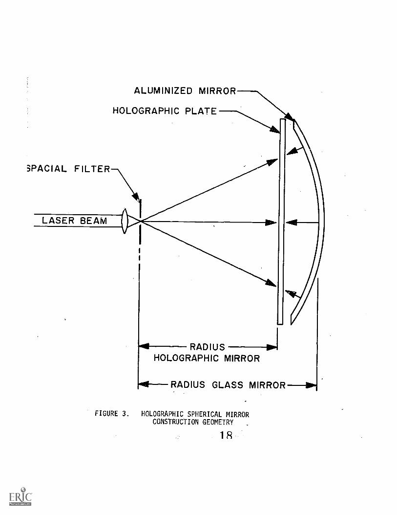
To produce a spherical mirror holographically, the filmin which the hologram would be recorded should be illumin-ated by two wavefronts, each originating in point sourcescoincident with its focus. Since a sphere has the two focicoincident at its center of curvature, to produce a holo-graphic spherical mirror, two wavefronts are used, oneemanating and the other converging at the same point whichwill become the center of curvature of the holographicspherical mirror (Figure 3).
6 17
SPACIAL FILTER
LASER BEAM
ALUMINIZED MIRROR
HOLOGRAPHIC PLATE
RADIUS --PiHOLOGRAPHIC MIRROR
RADIUS GLASS MIRROR
FIGURE 3. HOLOGRAPHIC SPHERICAL MIRRORCONSTRUCTION GEOMETRY

When the holographic mirror is illuminated, it willdiffract light. The diffracted wavefront will have similarcharacteristics to those of a reflected wavefront from aclassical mirror. If the hologram diffracts all of theincident light, it will be equivalent to a total reflectingmirror. If only part of the light is diffracted by the holo-graphic mirror, it will be equivalent to a partially reflec-ting mirror or beamsplitter mirror.
The holographic beamsplitter mirrors are reflectionholograms, which typically have a relatively narrow bandwavelength response. These are the so-called monochromaticholographic beamsplitter mirrors that have been used in themonochromatic holographic Pancake Window. The efficiencyof this mirror (as related to the holographic Pancake Win-dow transmission) is very high when used with monochromaticsources such as some of the very narrow band CRT phosphors(Figure 4). When used with white light (broad band) sources,the efficiency is low because of the mirror's chromaticity.
Tricolor Holographic Spherical Beamsplitter Mirror
A tricolor holographic mirror is a composite of threeholographic mirrors, each having a monochromatic (narrowband) response and a focal length which is identical at thepeak wavelength response of each hologram. The spectraldistribution response of these three holograms can be se-lected to produce a wide band spectral response with littleovrlap between monochromatic responses. The three mono-ch:::.omatic holograms can be recorded in the same film or indifferent films and can be assembled onto a common film sub-strate or on separate substrates.
Project Evolution
In specific applications HOEs should compete favorablywith lenses and mirrors, and as mentioned before, in thePancake Window configuration a holographic spherical beam-splitter could redude drastically the production cost andthe weight of the system.
A significant breakthrough achieved in this field wasthe in-house production of holographic films with overallcharacteristics superior to those of commercially availablefilms. The development of these films (ammonium dichromatephotbsensitized gelatin type film) led to the production ofvolume-phase holograms with a diffraction efficiency closeto 100 percent and no observable scattering. The capabil-ity of producing film of any size in the laboratory alsoeliminates the size restrictions imposed by having to de-pend on commerically available films.
198

100-
90-
70
60-
50-
40-
30-
10-
HOLOGRAPHIC
SPHERICAL
BEAMSPLITTER
F-NUMBER:0.56
0
480
20
P -44
PHOSPHOR
500 550
DIFFRACTION EFFICIENCY % VS. WAVELENGTH NM.
FIGURE 4. P-44 PHOSPHOR SPECTRAL DISTRIBUTION
600
21

To evaluate the optical performance of holographicelements which could be used in the Pancake Window infinitydisplay system, a 17 inch diameter holographic sphericalbeamsplitter mirror was produced and a Pancake Window as-sembled using this hologram as the spherical beamsplitterelement.
Also evaluated were the performance of a high powercontinuous wave (c.w.) argon laser with regard to its suit-ability to the fabrication of the HOEs; and the adequacyof the existing holographic facilities. New techniquesapplicable to the various steps in the preparation of theholograms were also developed and evaluated in the courseof this effort.
The use of multiple holographic Pancake Windows in asingle system was next investigated as part of this continu-ing development.
Holographic Pancake Windows. were evaluated not as singleelements but in a mosaic of three units butted edge to edgeand with a dynamic imagery display which could be drivenacross all three windows. There was.also a continued effortto improve the quality and repeatability of the hologramsas a result of what was learned in the fabrication of the17 inch holographic Pancake Window and subsequent developrrents
2.
Prior Project Analysis
The performance of the 17 inch holographic PancakeWindow manifested a series of defects and inconsistent re-sults which were not quite understood. Consequently, anin-depth analysis was started which concentrated particularlyon two areas:
1. the origin and possible elimination of ghost images,and
2. the influence of the control of environmentalparameters on the quality and repeatability of the hologram.
Successfully completed, this study revealed the newholographic ghost images were not inherent to the hologra-phic system but were caused by internal reflections duringthe construction of the hologram and by overly high valuesin the diffraction efficiency of the holographic beamsplitter.Consequently, these ghost images were eliminated by incor-porating a wet cell in the hologram construction geometryand by controlling the diffraction efficiency to values nothigher than 50 percent.
The study also indicated the need for a clean roomenvironment for the production of the holographic film and
lo 22

holograms and the necessity.for control of temperature andhumidity throughout their processing to achieve higherquality and repeatability. As a result, new holographiclaboratory facilities were built which provide a clean roomenvironment of "10,000" quality ("100" quality for filmcoating); humidity control to +1 percent and temperaturecontrol to +0.50C w.
The 17 inch holographic Pancake Window program also pro-vided valuable information relative to the capability andperformance of the high power c.w. argon ion laser forconstruction of the holograms, and the need for monitoringthe oscillation stability of the laser and the vibrationstability of the holographic recording geometry.
Implementing the wet cell in a previous project re-vealed difficulties in attaining the required stability.The wet cell, which was to contain a 24 inch by 21.5 inchholographic plate, was redesigned several times before aconfiguration was found which was relatively insensitiveto acoustical and mechanical vibration disturbances. Withthis wet cell, exposures of more than 20 minutes durationwere achieved with good results.
This prior project raised the problems of holographicwavelength bandwidth response, wavelength spectral peakpositioning stability, and shifting which were not formallyconsidered before. The spectral response of the hologramshould match the spectral response of the illuminationsource if .a maximum transmission efficiency in the hologra-phic Pancake Window is to be achieved.
It was found that the holographic spectral responseshifted with time to lower wavelengths (toward the blue)if the hologram was not properly sealed, and it also shiftedwith angles of incidence or large field-of-view angles.This spectral shifting renders more difficult the precisewavelength peak response positioning than is necessary ifnarrow spectral band illumination sources are to be used.
Techniques were developed in which holographic wave-length peak response positioning was accomplished to +2nanometers (nm). The spectral response shifting with timewas controlled with proper hologram drying and subsequentsealing to exclude humidity with a cover plate or by cemen-ting the hologram into the Pancake Window configuration.The spectral shifting with angle of incidence and/or field-of-view angle, if not possible to eliminate, can be ignoredif a wider spectral illumination source is used or if theshift is averaged with respect to the peak of a narrow spec-tral band source. However, a wider spectral source will.decrease the peak light transmission.
*See Appendix A.
11 23

With the new holographic facilities, holographic filmswere coated with very good flatness and uniformity. The re-peatability of the entire holographic process became excel-lent. The environmental controls provide the necessarymeans for holographic parameter evaluation and process cal-ibration. In this program, the requirements for producingholograms entirely free of cosmetic defects were investiga-ted and some blemish-free holograms were achieved experimen-tally. These techniques were not implemented in the finalproduct because program limitations gave priority to moremeaningful parameters.
The optical resolution of the holographic beamsplittermirror is excellent on-axis but deteriorates for off-axisangles or large field-of-view angles. This deteriorationis not an inherent limitation of the holographic processsince good off-axis resolution could be observed in selec-ted areas across the entire field of view and at the ex-treme angles. This problem was investigated but a completesolution has not as yet been developed.
Summarizing
Programs prior to this project have investigated tech-nologies to produce holographic optical elements, specif-ically holographic spherical beamsplitter mirrors. Problemareas were found which were resolved and the holographicprocess was developed to prove the feasibility and perform-ance of monochromatic holographic beamsplitter mirrors, in-tended primarily as replacements for the classical sphericalbeamsplitter glass mirror in the Pancake Window InfinityDisplay system. This replacement accomplished a consider-able reduction in the weight,and should eventually reducethe manufacturing cost of visual simulators using thePancake Window Display system.
The monochromaticity or narrow spectral bandwidth re-sponse of a monochromatic holographic mirror, although ac-ceptable for particular applications, does not provide afull color display capability.
Project Scope
The goal of this project is to produce a holographicspherical beamsplitter mirror that could be used in thePancake Window Display system to provide a full color re-sponse for visual simulation.
Since monochromaticity is a characteristic property ofthis holographic mirror, it was decided not to change it butto increase the spectral bandwidth response by means of a
12 24

combination or coupling of three single monochromatic holo-graphic mirrors.
These three monochromatic holograms, one peaking in theblue, another in the green, and another in the red, areequally spaced under the photopeak spectral visual distribu-tions. The spacing is such that the sum of the three mono-chromatic spectral distributions provides maximum spectralcoverage without producing detectable crosstalk between them.
The holograms could theoretically be manufactured inthe same holographic film or as separate holograms. Theapproach followed in this project was to manufacture a)a blue hologram using the 488.8nm laser line of an argon laserwith a spectral response peak at 488nm and with a spectralhalf-height bandwidth of 30nm; b) a green hologram usingthe 514nm line of an argon laser, with a spectral responsepeak at 550nm and with a half-height bandwidth of 30nm; c)a red hologram using either the 514nm line of the argon ionlaser or the 647nm line of the krypton laser, with a spec-tral response peak at 620nm and with a half-height band-width of 30nm (Figure 5).
These holograms were to be assembled preferably withthe three holographic films at the same plane, and con-sequently, they would have identical focal lengths toform the composite holographic beamsplitter mirror.
The assembly of the holographic films at the same planewas to be accomplished by a film transfer technique in whichone of the films is "peeled" from its glass substrate andoptically cemented to one of the other two holograms.Finally, the hologram with'the two films and the hologramwith the single film were to be cemented together film-to-film (Figure 6) .
The focal length of each holographic mirror is a func-tion of the construction geometry (Figure 3) and of itsspectral response.
Since it "reflects" by diffraction, these parametersare related by:
f Rr Rc c2 2
where:f = Focal length of the holographic mirror for the
illuminating wavelength.
Rr = Radius of'curvature of the holographic mirrorfor the illuminating wavelength.
Rc = Radius of curvature of the holographic mirrorfor the construction or laser wavelength. Also distancebetween the spatial filter and holographic plate in the
13 25

BLUE RESPONSIVE
HOLOGRAPHIC
SPHERICAL
B.S. MIRROR
RESPONSIVE
WAVELENGTH
ct
441
0300A-I-- 0021
4 I
ofco
z0
GREEN RESPONSIVE
HOLOGRAPHIC SPHERICAL
o B.S. MIRROR
RED RESPONSIVE
HOLOGRAPHIC
SPHERICAL
B. S. MIRROR
GAUSSIANz I
1
z0
I-co
0
3004 3004
<1 841
01 ofol
:2I(7,1
26LASER LINES. FOR HOLOGRAM CONSTRUCTION AND HOLOGRAM WAVELENGTH RESPONSE
27
FIGURE 5. TRICOLOR HOLOGRAM DESIGN SPECTRAL
VALUES, RESPONSE AND LASER LINES

MYLAR
GLASS rs
MYLAR
:AL CEMENT
GLASS
MYLAR
O. 15 nim
GLASS
FIGURE 6. -HOLOGRAPHIC FILM TRANSFER
BLUE HOLOGRAM
GREEN HOLOGRAM
RED HOLOGRAM
BLUE HOLOGRAMGREEN HOLOGRAM
RED HOLOGRAM
BLUE HOLOGRAMGREEN HOLOGRAM
construction geometry.
A c = Wavelength used during the .construction of thehologram or laser wavelength.
A r = Wavelength used in viewing the hologram orspectral wavelength peak response of the holographic mirror.
A variation in the spectral response will cause a vari-ation in the focal length of the monochromatic mirror anda mismatch with the others in the composite mirror. Con-sequently, the positioning of the spectral response peakand the control of the spectral response shifting are fund-amental in this project.
The production of a holographic beamsplitter with ared response had been previously accomplished but.not bydesign. The controlled production of a red response holo-graphic beamsplitter was also a specific task of this pro-ject. (Holograms designed to have a response in the greenhad been previously obtained with an unwanted red response,probably due to a faulty preparation of the gelatin film.)

SECTION II
INVESTIGATION AND DEVELOPMENT OF HOLOGRAPHICMIRROR RESOLUTION AND SPECTRAL RESPONSE CONTROL
This project encompassed the fabrication of a tricolorholographic mirror as a composite of three monochromaticholographic mirrors and the evaluation of its performance.
The production of a blue and a green hologram hasalready been accomplished but further development was nec-essary in the areas of holographic mirror resolution andin controlling the spectral response of these holograms.These holograms should spectrally peak at a specific wave-length and not shift or change their spectral response. Thetolerances are small since a change,in the spectral responsewill cause a changein the focal change of the monochro-matic holographic mirror and consequently, a mismatch ofthis mirror (in focal length) in the tricolor compositemirror.
The optical resolution of the holographic mirror de-teriorates, generally, but not always, with off-axis anglesor large field-of-view angles. Experimental data seemto indicate this deterioration is principally caused bydefects in the hologram itself and not by a limitation inthe holographic geometry (holographic optical aberrations)or in the holographic basic process.
Several theories have been formulated and investigatedto find a solution for these problems.
Resolution Improvement
The optical resolution in the monochromatic (blue andgreen) holographic spherical beamsplitter mirrors had thefollowing characteristics:
1. On-axis resolution is as good as 1 minute of arc.
2. Off-axis resolution does not generally deterior-ate if the eye position is shifted so that the line-of-sight passes through the center of the mirror for anyviewing angle.
X73.0

3. Off-axis resolution generally deteriorates withincreased angles when viewed from the center of the exitpupil.
4. In selected areas across the entire field of view,the resolution is as good as that on-axis for specificviewing angles and head positions not necessarily in the"pupil" volume.
5. In select areas, and even at the extreme field-of-view angles, the resolution is as good as that on-axis whenviewed from the "pupil" volume.
6. Areas of bad resolution (and good resolution) seemto be associated with an "optical texture" of the hologra-phic film.
Five hypotheses were considered to analyze thisproblem:
1. Angles of holographic reconstruction departgreatly from angles of holographic construction (Bragg
angle).Because of the discontinuity in the deterioration
of the resolution, this hypothesis assumes the possibilityof an aspherising effect caused by distortion of the planesof diffraction in the good resolution areas.
2. The holographic film, in the swelling process,distorts the planes of diffraction in a random manner mostlikely associated with cosmetic defects and variations inthe physical characteristics of the films.
3. The holographic film, in the swelling process, is
affected by a radially directed strain which will deformthe planes of diffraction.
4. The holographic film is not uniformly hardenedand during the holographic process some areas on the filmare distorted or will have different holographic responses.
5. Non-uniformities of the illumination during theconstruction (exposure) of the holograms could produce dif-ferent hardness on particular areas of the gelatin film.
Four experiments were conducted:
a. Holograms were produced with different geometries.Different holographic spherical mirrors, paraboloids, el-lipsoids and spheroids were made and compared for opticalresolution.
The gross change in resolution from area to areain the holographic film was observable in all the mirrors
18
and no specific improvement could be related to a particulargeometry. No distortion related to a particular geometryor to an aspherising effect was observed. The changes inthe geometry were produced by varying the distance betweenspatial filter and aluminized master mirror from the focusof the mirror (to produce a parabola), to a distance be-tween the focus and the center of curvature (to produce anellipse) to a distance equal to the center of curvature (toproduce a sphere) and to a distance greater than the radiusof curvature (to produce again an ellipse). Holograms werealso produced distorting the illumination wavefront slightlywith a cylindrical lens.
b. A large number of holograms produced before thiscontract were analyzed for common characteristics relatedto resolution or the lack of resolution. It was recognizedthat old gelatins and old photosensitized gelatins gavebetter hologram resolution, that slow-dried gelatins gavebetter resolution than fast-dried gelatins; and that thosegelatins requiring chemical hardening to remove scatteringdue to gelatin cracking had better resolution than thosegelatins not subject to chemical hardening (Table 1).
A unique characteristic of each of these gelatinshaving superior resolution was their relative hardness. Agelatin's age, whether photosensitized or not, will affectits hardness5; a 2-month-old gel will have more rigiditythan one that is a day old. An old photosensitized gelatinwill have been subjected to a dark reaction, hardening thegelatin and lowering its sensitivity to light. Those gel-atins dried slowly are harder than those dried quickly dueto a longer period of a gelation allowing more crosslinksto be formed between gelatin molecules. A chemical hard-ener, e.g. bisulfate, will react with the ammonium dichro-mate sensitizing dye to also form crosslinks.
Any or all of these processes will yield a harder gel-atin and a hologram with better resolution due to gelatinintegrity not allowing the planes of diffraction to deform.To prove this, the gelatins for subsequent holograms wereprehardened. This resulted in better resolution in thoseholograms but lower emulsion sensitivity to light. (Thereis a trade off between gelatin hardness and plate sensitivity.)
It has not as yet been determined in which steps ofthe holographic process the film needs to be further hard-ened or it a new film formulation will be required. Also,it has not yet been proven that the hardening parameter isthe single cause for the deterioration of the resolution.
c. To study the possible effects of radial strain anddeformation of large plates during the swelling of the film,the film in the large size holograms was cut in successivecircles from the center of the plate outward. Radial cuts
3219

TABLE 1 - RELATIVE RESOLUTION VS.GELATIN HARDENERS
Holograms ' Relative ResolutionProduced in/with JSuperior Poorer
Aged gelatins X
Aged photosensi- .
tized gelatins X
New Gelatins X
Fast Dried_Gelatins X
Slow Dried Gelatins . X
Chemical afterhardening X
Chemical pre-har-dening .X
No Chemical hardenin X
33
20

crossing the circles were also made.
These holograms were exposed and processed togetherwith other holograms with similar film characteristics butwithout being cut. The comparison of these holograms pro-duced no evidence of strain or deformation caused by ra-dial forces during the swelling of the film. Nor was thereany improvement in resolution correlated with the hologramson film which had been cut.
In a similar experiment, small holograms were simul-taneously exposed side by side simulating a large size holo-gram. The comparison of this composite hologram, after pro-cessing, with a large hologram revealed no significantdifference.
d. To produce a uniform illumination, special opticsfor expanding the laser beam were designed and manufactured.These optics consist of a Galilean telescope which will col-limate an expanded laser beam, transmitting only the mostuniform part of the beam's Gaussian intensity distribution,with a variation not greater than 50 percent from the centerto the edge. This telescope will also minimize later dis-placement (of the focused laser beam) associated with dif-Eerent modes of laser oscillation.
The implementation of these optics improved the qualityof-the holograms and the resolution but is not the completesolution of the problems.
It is generally concluded that the hardness parameteris most closely related to resolution and that its com-plete control could solve the resolution problem. However,a process which totally eliminates the resolution deteri-oration has not yet been found or formulated. The improve-ment achieved thus far is notable, and, it expected thatadditional development work will achieve a complete solutionof the problem.
Spectral Response Control
To be successful in the production of the tricolorhologram, the spectral response of'each of the three mono-chromatic holograms must be controlled. The following re-quirements apply:
1. The monochromatic hologram should respond to thedesigned wavelength and should peak at a wavelength cor-responding to the focal length calculated with the construc-tion geometry. The wavelength peak position toleranceshould be better than +2nm._
2. The position of the monochromatic holOgram spectral
3421

response peak should be stable and no wavelength shift willbe allowable.
3. The wavelength shift with angles of incidence andfield angles should not produce a change in the focal lengthwith different values for each mirror.
To test and further development the positioningof the wavelength response peak, the following areas wereinvestigated:
1. Film hardness: It was established that the hard-ness of the film will determine the final stable positionof the hologram response. Those holograms whose gelatinswere harder due to chemical hardening after exposure hada lower peak wavelength resnonse than those not chemicallyhardened (Figure 7).
2. Use of plasticizers: If the hologram was processedwith triethanolamine or some other plasticizer was incor-porated in the gelatin, then the gelatin's final state willbe swollen beyond its normal thickness causing a largerseparation of the planes of diffraction. This increasedseparation will cause the peak wavelength response to bedisplaced to a longer wavelength (Figure 8).
3. Effect of water retention of gelatin: It was seenthat if the gelatin was exposed less than 24 hours afterphotosensitization, the final peak wavelength response wouldbe lower than if the gelatin was exposed some longer time,e.g. 20 days, after photosensitization. This drying outof the gelatin will cause the peak wavelength response tobe approximately 20nm higher than if the gelatin were notallowed to dry out. The water content of the gelatin filmas a function of the environmental humidity in the dryingand storage of the film before it is exposed, has a notice-able effect in the position of the spectral peak (Figure 9).
To achieve a hologram whose peak wavelength responsewould not shift over long periods of time, the followingareas were investigated:
I. Effect of drying speed on spectral shift: Holo-grams were dried at various rates after processing by ad-justing the environment with regard to relative humidityand temperature. It was found that regardless of rate ofdrying, the holograms reached a specific peak wavelengthresponse. This peak response was only a factor of gelatinprocessing prior to or after exposure. A hologram dried ina high-temperature low-humidity environment, 50°C and 20percent relative humidity (R.H.), would reach a stable peakwavelength response in approximately one day, while a holo-gram dried slowly at a higher relative humidity, e.g. 45percent relative humidity, would shift slowly over
22 35

. 8
.6
.4
.2
1 1 I I I 1 1
475 500 525 550 575 600 625
WAVELENGTH, NM
FIGURE 7. FILM HARDNESS Vs. SPECTRAL RESPONSE PEAK.
CONSTRUCTION WAVELENGTH AT 514nm
SCALE OF HARDNESS: ZERO FOR TOTAL FILM WHITENINGAND 1 FOR A DIFFRACTION EFFICIENCY LESS THAN 10%

1.
.8
.4
.21
I
475 500 525 550 575 600 625
WAVELENGTH, NM
FIGURE 8. ADDITION OF PLASTICIZERS Vs. SPECTRAL RESPONSE PEAK.
CONSTRUCTION WAVELENGTH AT 514
SCALE OF ADDITION OF PLASTICIZERS: ZERO FOR NOPLASTICIZERS AND 1 FOR LOSS OF ADHESION OF THEFILM TO THE SUBSTRATE.
37

GELATINRETICULATE
475 500 525 550 575 600 625
FIGURE 9.
WAVELENGTH, NM
SPECTRAL RESPONSE PEAK Vs. ENVIRONMENTAL HUMIDITY,BEFORE EXPOSURE.
CONSTRUCTION WAVELENGTH 514nm

approximately two weeks to the same final peak wavelengthresponse (Figure 10).
2. Effect of relative humidity on hologram: It wasfound that a hologram's peak spectral response, if it isnot sealed, would vary from its final "stable" positiondepending on either water absorption or dehydration due toits surrounding environment. The amount of shift was re-lated to the hardness of the gelatin since water absorptionis dependent of gelatin hardness. For example, a plate re-moved from an environment of 3, °C and 20 percent R.H. andplaced in an environment of 22 C and 30 percent R.H. showeda peak wavelength response increase from 537nm to 544nm,(Figure 11).
3. Effect of sealing the hologram with various cementson final peak wavelength response and shift speed: Holo-grams which had reached their stable spectral response andwere then sealed with a layer of cement, or cement and acover glass, remained at that Peak spectral response. Ifthe hologram had not been properly dehydrated and wassealed, a shift in wavelength would occur very slowly tosome final wavelength response. This shifting may takesix months, for example, depending_ only on how dehydratedthe gelatin is when it is sealed. The amount of shiftingwhich will occur cannot be accurately predicted, so hologramsshould be sealed only after they reach their stable peakwavelength response (Figure 10).
The cements used were a potting compound, a polyestercasting resin, and two Part epoxy.
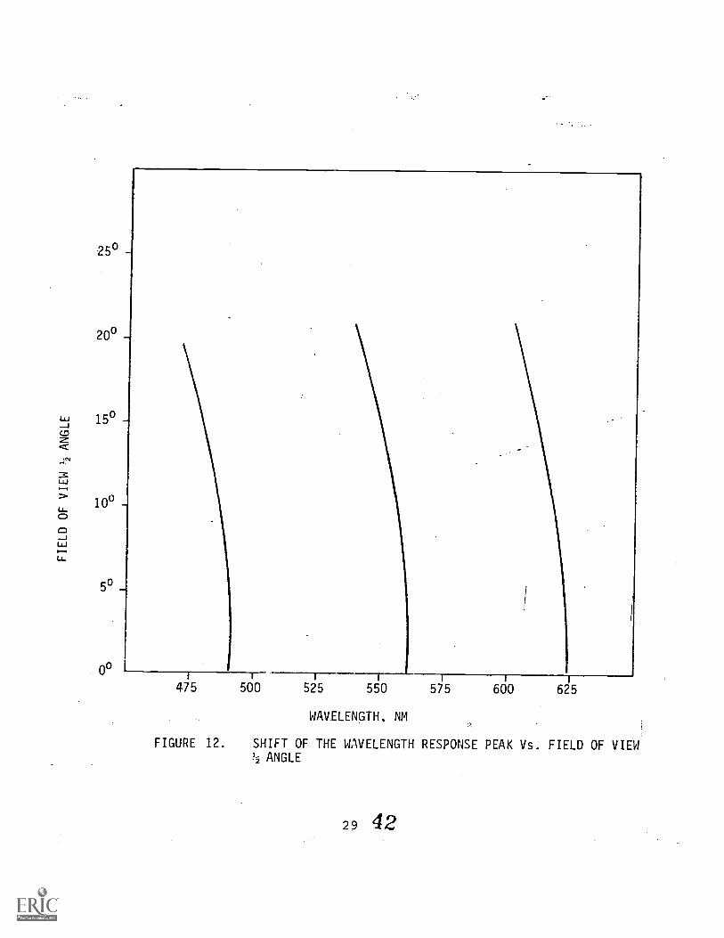
In order to determine the shift of the wavelengthresponse peak with field-of-view angles, holograms weremeasured with spectral responses in the blue, in the greenand in the red.
The holographic wavelength shift with respect to fieldangles seems to be independent of the spectral responsePeak and only dependent on the value of the angle. Thisresult is not totally conclusive since inconsistencies havebeen noted which have not yet been completely analyzed(Figure 12).
The wavelength shift (even independent of the hologramresponse) will affect the focal length of each hologramwith factors which are dependent on the construction-recon-struction wavelengths ratio. This problem also has not yetbeen completely analyzed.
3926

650 625 600 575 550
FIGURE 10.
WAVELENGTH, NM
525 500 475 450
SHIFT OF THE WAVELENGTH RESPONSE PEAK Vs. TIME AFTERTHE HOLOGRAM HAS BEEN CONSTRUCTED
Unsealed HologramSealed Hologram after 4 hours of construction
(a) Dehydrated in an oven for several hours at 100°C(b) Dried in an environment of 20% relative humidity(c) Dried in an environment of 45% relative humidity(d) Dried in an environment of 60% relative humidity
27 40

100
80
201
1
530 535 540 545 550 555 560
FIGURE 11.
WAVELENGTH, NM
RELATIVE HUMIDITY Vs. SHIFT IN WAVELENGTH RESPONSEPEAK (FOR HOLOGRAMS WHICH HAD BEEN DEHYDRATED ANDSTORED AT 20% RELATIVE HUMIDITY)
241
250
20"
150 -+
50
1 1 ---r475 500 525 550 575 600 625
WAVELENGTH, NM
FIGURE 12. SHIFT OF THE WAVELENGTH RESPONSE PEAK Vs. FIELD OF VIEW1/2 ANGLE
29 42

SECTION III
INVESTIGATION AND DEVELOPMENT OF RED RESPONSE HOLOGRAMS
The development of techniques for producing the redspectral response hologram evolved into a parallel inves-tigation of two basic approaches with the emphasis shiftingfrom one approach to the other in direct relation to thedegree of success or failure experienced as the workprogressed.
A red hologram (holographic spherical beamsplittermirror Tr a spectral response in the red region of thevisual spectrum) could theoretically be produced with the514nm green line of a c.w. argon ion laser if the hologra-phic film is treated chemically to have a spectral responseat a red wavelength rather than at the green constructionwavelength. The advantages of this technique were three-fold:
1. The three monochromatic holograms could be pro-duced with the available argon laser, avoiding the need fora krypton or other red laser as well.
2. The gelatin film photosensitization process neednot be modified.
3. The actual production of this type of red responsivehologram had already been accomplished on a trial basis.
The disadvantages were primarily concerned with thelarge wavelength shift between construction and reconstruc-tion or construction-reconstruction wavelength ratio whichmay produce holographic aberrations and affect the hologra-phic mirror optical performance.
A red hologram could also theoretically be producedwith the 647nm red line of a krypton laser and the hologra-phic film treated, if necessary, to spectrally respond toa slightly lower wavelength of 620nm. The advantages men-tioned previously with the argon ion laser now become dis-advantages and conversely, the disadvantages now become ad-vantages, indicating the possibility of better opticalperformance.
The most critical problem was the photosensitization ofthe dichromate gelatins for the red. Although this problem
3043

had already been investigated by other researchers 3, the ex-
pected results for this particular holographic geometry werecompletely uncertain.
Note that a ruby laser or a yttrium aluminum garnet lasercould also be used to produce a red hologram. These a'epulsed lasers which ideally would be more desirable if theyhave the power required to expose the relatively slow am-monium dichromate gelatin films. Considering the power ofa commercially available ruby laser at 10 joules (J) /pulseand considering single pulse exposures,-because of coherencerequirements, the available total energy for exposure ofthe plates would be 120 times greater with a c.w. kryptonlaser (2 watt (W) useful power) for an exposure durationof 10 minutes. (Irradiated energy,on the film in joules(J) = power in watts (W) x exposure duration in seconds (t),so that for the c.w. krypton laser, 2 watts x 600 seconds =1200 joules compared to the single pulse 10 joules of thepulsed lasers.
Construction of the Red Hologram with the Argon Ion Laser
Initial Results. Experiments were carried out to in-vestigate the increase in the amount of swelling in a holo-graphic film when plasticizers were added in the develOpingprocess. This additional amount of swelling could pro-duce a permanent magnification in the separation of theplanes of diffraction and consequently a higher wavelengthspectral response (toward the red if constructed in thegreen).
Holographic plates were exposed with the 514nm line ofthe argon ion laser and developed with the addition of aplasticizer (triethanolamine) treatment. The holographicresponse shifted to the red and seemed initially to be stable.Some of the plates were sealed with a glass cover plate andall were measured at intervals of time to detect any pos-sible wavelength shifting or instability.
It was found that the plates that were sealed remainedin the red and shifted only a few nanometers but the un-sealed holograms shifted after a few weeks to the yellow-green region of the spectrum.
The most unexpected problem was the anability to re-peat the above results, once the existing stock of pre-viously coated gelatin films was exhausted. The hologramsproduced with freshly coated gelatin films shifted to thered when treated with triethanolamine, but the spectral re-sponse shifted back to a yellow-green spectral region ina time period of hours, even when cemented with a coverglass.
4431

These results forced a re-evaluation of the problemand experiments were planned to investigate the parameterswhich might be influential in the construction of the redhologram with the argon ion laser. Also investigated wasthe construction of the red.hologrm with the krypton orother red-emitting lasers.
Investigation of Parameters
Experiments were conducted to determine the effect ofthe various parameters on the spectral shift from 514nm ofthe construction geometry to the 620nm desired wavelengthholographic reconstruction response, and also on the sta-bility, with time, of the spectral response.
1. Effect of aging of the gelatin film: In the at-tempt to repeat the initial results ir obtaining a redhologram with the argon laser, the parameters in the holo-graphic process were identically repeated. One parameter,the gelatin film, could not be repeated because the oldstock of films was depleted, and new, freshly-coated ma-terial had to be used. To investigate the effect of oldvs. newly coated films, gelatin films were aged by an ar-tificial process and by a natural process. In the arti-ficial process the gelatin films were baked and cooled forseveral cycles. In the natural process the films werestored for a period of 4 months.
The results show no direct correlation between theage of the film and the capability of the hologram to main-tain red response. All of the holograms shifted back fromthe red tothe green in a matter of hours.
2. Effect of exposure energy: Holographic rateswere exposed with different energies, from 10mJ/cm toarCriem , and the plates were developed and swelled usingtriethanolamine.
The very-low exposure plates produced hologramswith weak signal and/or too much scattering due to retic-ulation of the gelatin film during drying. The plates withlarge scattering had a red response which was relativelystable. The holograms exposed with densities greater than200mJ/cm 2
produced red holograms which shifted back to thegreen. The higher the exposure energy, the faster the shiftback. The speed of shifting was constant above 500mJ/cm2(less than one hour)(Figure 13).
3. Effect of plasticizers and hardeners: To verifya possible beneficial action in the swelling of the gelatinfilm with the addition of plasticizers and hardeners, ex-periments were carried out with different formulations. The
4532

10.000
1 . 000
100
1O--4
1 i i i 1 1
475 500 525 550
WAVELENGTH, NM
FIGURE 13. RED RESPONSE Vs. EXPOSURE ENERGY
CONSTRUCTION WAVELENGTH = 514nm
575 600 625
4633

plasticizers used were triethanolamine, glycerol, and ethy-lene glycol and they were added to the gelatin. solution be-fore the film was coated and during other steps in the holo-graphic process. The concentrations were also varied.
The hardeners used were formaldehyde sodium bisulfate,sodium meta-bisulfite, methanol, and Kodak Rapid Fixer.The formaldehyde was added to the gelatin solution beforethe film was coated and the other hardeners were used in har-dening baths at different steps during the holographic pro-cess. Besides the chemical hardeners, the films were alsohardened by baking them before photosensitization.
The results show a general tendency of the plates torespond in the red when plasticizers were used and to rer-spond in the green when hardeners were used. The plasti-cizer caused the film to reticulate.or to exhibit very non-uniform characteristics. The hardeners produced very uni-form films, relatively low diffraction efficiencies and aspectral response very close to the construction wavelength(Table 2).
4. Effects of .various gelatins: Gelatin films werecoated and processed using pure gelatins of different types.The concentration of gelatins was at a maximum when thegelatin coated at 30 °C gelled as soon as it was spread onthe glass plate with a thickness of .5 cubic centimeter(cc) per square inch. The minimum concentration was themaximum concentration diluted four times with distilledwater. Several gelatins were used with different bloom val-ues and acid or alkaline processed.
The holograms produced with these gelatins pre-sented different characteristics and did not give any pos-itive solution for the red response. Considerable effortwas expended dn maximizing the formulation of each gelatinto improve adhesion to the substrate, hardness, sensitivity,swelling, etc., but in general, not one of these gelatinformulations could produce better results than the stan-dard gelatin formulations which are routinely used for theproduction of the holographic films (Table 3).
5. Effect of gelatin thickness: The standard gelatinformulation was also coated in various thicknesses corres-ponding to20.25, 0.5, 2 and 4 times the standard thicknessof .5cc/in . It was difficult to remove the photosensiti-zing dye from the heaviest thickness but this was the onewhich produced better and more stable red response holo-grams. Attempts tolowerthe concentration of the dye andto prolong the washing time were not successful, and a goodred response was incompatible with a clear plate and ac-ceptable diffraction efficiency (Figure 14).
34 47

TABLE 1 - EFFECT OF PLASTICIZERS AND HARDENERS ON THE PEAK RESPONSEWAVELENG
Plasticizers Hardeners.B-= Added Before-Expo-Sure-b = Used Before ExposureA = Used After Exposure
ResponsePeak -.Remarks
Wavelength
Triethanolamine B 10% by wt.
A 13%
Red High Scat-tering
Yellow Good
Glycerol B 20% to 80% by wt. Green-Yellow Good
Ethylene Glycol B 20% to 80% solution Green-Yellow Good
Fon-nalddlyde B 20% to 80% by wt. Green Low Dif-fraction
A 40% solution Green Normal
Methanol b 100% pure Film Foggad
A 100% pure Green .Low Dif-fraction
Kodak RapidFixer
b Green Low Dif-fraction
A Standard Green No Effect
Sodium Bi-sulfate A 1% solution Green
Sodium Bi-sulfateand
A 1% solution Green
AmmoniumDichromate 1% solution Green
*Triethanolamine *ChromiunSulfate . A 13%/2.5% to 10% sol. Green
Triethanolamine ChromiumPotassiumSulfate A 13%/2.5% to 10% sol. Green
Triethanolamine Aluminum SurfaceSulfate A 13% to 26% sol. Red Scattering
Construction wavelength atB= Added Before Exposure:
b= Used Before Exposure:A= Used After Exposure:
*The hardener solution used
514nmChemical added to the gelatin solution beforeplate was coated.Film immersed in the chemical solutionFilm immersed in the chemical solution
after the plasticizer solution.
354 8

TABLE 3 - GELATINS
Supplier .Type Characteristics
"A" Co.
"B" Co.
"C" Co.
1099 - Calfskin
5247 - Pigskin
G-8
G-9
15 CP Neutral
Iso.4.7; Strength 297
Iso.5; Strength 399
275 Bloom
100 Bloom
49
36

4N
2N
14
1/2N-
1/4N
475 500 525 550 575
WAVELENGTH, NM
FIGURE 14. WAVELENGTH PEAK RESPONSE Vs. THICKNESS OF GELATINE.
CONSTRUCTION WAVELENGTH 514
SCALE N =30 MICRONS ^= STANDARD THICKNESS
600 625
37 505

6. Effects of the photosensitization process: Theconcentration of ammonium dichromate appears to have noeffect on the spectral response, while the dryness of thefilm (when exposed after photosensitization) seems to havea strong effect. Plates which were photosensitized anddried in a high 1%,umidity atmosphere all have A stable redresponse but alcio reticulated and have excessive scattering.Plates which %::ere photosensitized and dried in a dry airatmosphere responded spectrally in the green and did notexhibit scattering.
Pi:tempts to reduce the scattering in the red ho::gramswere f.-artially successful in the sense that the scatteringwas eliminated but the plates showed a nonuniform responsewith different areas spectrally responding in the red,green, yellow, etc.
The red response associated with high humidity in thedrying of the photosensitized plate was correlated withholograms produced in the past, which after more than 3 yearsstill showed a good red spectral response but also exhib-ited scattering and nonuniformities. These early red re-sponse holograms probably resulted from a lack of environ-mental controls during that stage of this development.
7. Effect of sealing the hologram: An investigationwas made into the possibility of "freezing" or stoppingthe shift back from the red to the green by cementing thehologram using a sealer or a coverplate. Various typesof adhesives and sealers were used: spray sealer, one partadhesive, fast setting epoxies, and slow setting epoxies.In general, the holograms shifted back, but a few nanome-ters less than the holograms that were not sealed or cemen-ted. Although all of these sealers and cements have lowwater absorption characteristics, they cannot be consideredas perfect water barriers (Table 4).
8. Effect of hardeners after the gelatin films havebeen swelled: A dichromate gelatin, reflection volume-phase type hologram constructed with the 514 line of aargon laser will normally start diffracting at higher spectral wavelengths (yellow-red) while it is drying and thisresponse will become greener as the hologram dries. The"natural stopping" position of the spectral response peakis related to the construction processing and gelatinparameters. Also, the more the hologram swells-or isforced to swell with swelling agents, the higher the wave-length or the stronger the response the hologram will haveinitially in the red. Ideally if the hologram could be"frozen" in this swollen state, a permanent red responsecould be obtained. The attempts that were made at sealingor cementing the holograms in that state were not success-ful. Another alternative was to harden the hologram in
5138

TABLE 4 - HOLOGRAM SEALERS
SEALER TYPE REMARKS
"A" Cement Potting Compound Good when used with a coverglass. Frosted finish whenlcoated by gravity w/outcover
"B" NL410 PolyesterCoatingResin
Same as "A" Cement above
"C" 2 tonclear cement 2 part slow
setting epoxy
Difficult to work with;viscosity causes trappedair bubbles
InvisibleArmor
PolyurethaneSealer
Frosted finish unacceptablelnot used with cover glass
Collodian Orange Peel occurred; notused with cover glass
KrylonClear
AcrylicSpray Coating
Frosted Finish unacceptable
LableGlaze
Plastic Glaze Difficult to attain a flatuniform coating
E-PDX-E 5.
2 part fastsetting epoxy
Difficult to work with;viscosity causes trappedair bubbles
this swollen state to make it more difficult for it to re-turn to the normal state.
This attempt produced the best results, and a perm-anent, stable red response was obtained. The repeatabilityand-uniformity was good but the quality was not yet accep-.table because of considerable scattering. This processwas developed further and was used in the production of thefinal red hologram assembled in the tricolor holographicPancake Window (Table 2).
Construction of the Red Hologram with a Red Laser
In a parallel effort with the, development of tech-niques for producing a red hologram with an argon laser,experiments were carried out to investigate the feasibil-ity of producing the red hologram with a red laser, spe-cifically a krypton laser.
The basic problem was to achieve a photosensitizationprocess for the dichromate gelatin films which could beused with the red laser lines, and with a sensitivity com-patible with the available laser power. The normal pro-cess of photosensitization with ammonium dichromate pro-duces films whose sensitivity is relatively strong in theblue, low in the green, and non-existent in the red.
Initial experiments. This investigation was startedby experimenting with a formulation for red photosensiti-zation of ammonium dichromate film which had been reportedin the literature. Basically, the formulation consistedof the addition of an extra dye, methylene green, to thephotosensitization process. Two things were, nevertheless,different: (a) the reported formulation has been used withcommercially available photographic gelatin plates, and (b)the holographic geometry used two separate wavefronts eachof which will be incident at the plate from an oppositedirection. In this project the gelatin films have differ-ent characteristics than the commercially available filmspreviously mentioned, and the holographic geometry requiresthat one of the two interfering wavefronts used in recordingmust pass through the film twice.
To separate the influence of these two different con-ditions, the red photosensitization process was exactlyrepeated as reported in the literature and used with thesame type of commercially available gelatin film 649 Fplates. The geometry of holographic construction waschanged for the back mirror geometry used in this project.With this geometry, if the optical density of the plate istoo high, the wavefront passing through the plate twice will
4r53
not have enough intensity to interfere, being mostly absorbedin the first pass. These first experiments were carriedout with a 5mW He-Ne laser (while waiting for the deliveryof a high power (15 watts) c.w. krypton laser.) The laserbeam was expanded to a minimum to simulate the exposureenergies which wcald be used. The results were completelynegative, and no signal could be detected in the hologram.
In the second experimental step the mentioned formula-tion was modified (with the addition of potassium dichro-mate) a:Id calibrated to be used with the back mirror geom-etry. The dye's concentration, especially, has to bedrastically reduced to compensate for the extra absorptionin the gelatin plates used (not as hard as the Kodak plates)and to achieve an optical density compatible with a doublepass of one of the wavefronts.
The results obtained using this new formulation pro-duced not only a holographic signal but the film sensitiv-ity was much higher than the one reported with the originalformulation. Using the 3mW He-Ne laser, a red mirror of1-inch diameter and 10-percent diffraction efficiency wasproduced with a 5-minute exposure. The repeatability ofthe photosensitization process was poor for this highersensitivity film, and the dyes have the tendency to cry-stallize over the film after photosensitization.
The Krypton laser. The krypton laser which becameavailable was a 16-watt-rated model similar to the argon
-laser. The 16-watt all-lines power was reduced to about8 watts when the red 647 emission line was isolated. Afurther reduction of power was caused by the use ofanintra-cavity etalon which forces a laser oscillation atsingle longitudinal mode. This is required to obtainenough coherence length to produce interference with theback mirror geometry. The final usable power was between3 and 4 watts.
An external etalon was used to monitor the singlemode emission frequency and the stability of oscillationof the laser. An oscilloscope constantly displayed thisinformation.
Tuning this laser for maximum output was difficult,and stability and performance were not as good as thatof the argon ion laser. Nonetheless, the unit operatedwithin requirements and was not a limitation nor an ob-stacle in the production of the red hologram.
Experiments using the krypton laser. With more poweravailable, the red photosensitization process which wasdeveloped with the He-Ne laser, was tried with large sizeplates and with the krypton laser.
5d

After initial difficulties in repeating the earlierresults, the holograms could not be simultaneously pro-duced with high diffraction efficiency and uniformity ofresponse. The spectral response was red in some areas andgreen or yellow in other areas. The yield of good photo-sensitized plates was poor and most of the plates hadcrystallization which could not be removed. Attempts todecrease the crystallation resulted in holograms with verylow diffraction efficiencies. Another undesired charac-teristic of these red holograms was a very wide spectralresponse which made the plates unusable as monochromaticmirrors for the tricolor mirror.
Further development of the photosensitization processproduced a large size holographic plate with good red re-sponse in the desired 620nm region, with good uniformity,with narrow bandwidth response but with very low diffrac-tion efficiency. The optical mirror resolution at thisstate of development was comparable to or better than theresolution obtained with the final red hologram producedwith the argon ion laser.
The investigation with the krypton laser was inter-rupted since the parallel effort in the production of thered hologram with the argon laser was progressing fasterand indicated a shorter and more secure approach to thesuccessful fabric.ation of the red hologram.
This incomplete investigation (which was later re-sumed) has not yet permitted a comparison of the opticalperformance of these m!_rrors with the ones produced withthe argon laser. The production of the red hologram withthe krypton laser seemed to be achievable but its justif-ication as a mirror of better optical performance couldnot be evaluated due to the very limited quality and lowdiffraction efficiency of the holograms produced. Theoptical performance of both types ofrmirrors need furtherimprovement to achieve a minimum quality for a meaningfulcomparison.
Experimental conclusions. Both approaches, the fabri-cation of the red hologram using an argon laser or akrypton laser seem feasible but the techniques need to befurther developed. The continuation of the effort followingthe argon ion techniques was justified as a shorter approachin achieving a final usable hologram for the tricolor holo-graphic Pancake Window. With regard to predicting achiev-able optical performance, the actual state of developmentof both types of mirrors is such as to preclude drawing ameaningful conclusion.
42
5r-

SECTION IV
COUPLING OF THE HOLOGRAPHIC MIRRORS
General
The tricolor holographic beamsplitter mirror will bea compound hologram which will spectrally respond in threeselected ranges (blue, green, and red). These selectedranges have been designed to cover the visual spectrum insuch a way that maximum coverage without cross talk be-tween colors is obtainable. Since the focal length of aholographic mirror is dependent on the wavelength, themirror will produce color dispersion. The color disper-sion is reduced as the spectral response of the hologra-phic mirror is made narrower. That is the reason forusing three holograms, each with narrow spectral response,rather than one covering continuously the visible spectrum.
The recording of these three holograms could theor-etically be made in the same holographic film-or in sep-arate films. Also, they could have the same focal lengthif the three holograms are in the same plane or have thesame focus (in the Pancake Window configuration) althoughphysically separated.
Experiments were carried out to evaluate differentapproaches.
Experimental Evaluation
Double exposed hologram. Two holograms could be ex-posed in the same film and the third hologram produced soit could be cemented film to film. The three hologramswill then be practically in the same plane (within 100nm).
The theory for plane holograms predicts that the dif-fraction efficiency in a multiple exposed hologram will beinversally prop9rtional to the square of the number of holo-grams recorded. For the volume-phase type holograms usedin this project, the experimental results have demonstratedmuch higher diffraction efficiencies. It seems possiblethat usable holograms could be produced.
Two different techniques could be used:
5643

1. The holographic film is exposed twice using twodifferent wavelengths and geometry. The film is photo-sensitized only once, and it is also developed once.
In this technique a holographic film was exposedto the 488nm line of the argon ion laser. Covering theplate, the geometry was then changed for 514nm argon il-lumination. This is necessary to change the laser emissionline (using only one laser) and to vary the holographicfilm spatial filter distance to compensate for the varia-tion in focal lengths with the wavelengths. After the holo-graphic film has been exposed with the green light, theplate is developed and dried with the standard process.
The results were positive but the maximum diffractionefficiency obtainable was not completely established. Adeterioration of the optical performance of these mirrorswas not noticeable.
2. The holographic film is exposed twice using twodifferent wavelengths but is also photosensitized twiceand developed twice.
With this technique a hologram is produced in thestandard way, say for a response in the blue. After thehologram has been tested and accepted, it is again photo-sensitized (and apparently losing the blue response orany holographic response) and is exposed to another wave-length, say the green. When the holoaram is developedand dried, not only the green response but the originalblue response is present in the hologram.
This technique has proven to be very promisingand diffraction efficiencies of 50 percent are very likelyto be achieved.
Separate holographic films. The holograms are pro-duced independently and these approaches refer to thetechniques for placing the holograms in the same plane orwith a minimum of separation.
1. Film transfer: With this technique the threeholograms are produced and tested separately.
One of the holograms is cemented to a sheet ofMylar or other appropriately flexible substrate. The ad-hesion between plastic, cement, and gelatin is chosen tobe stronger than the adhesion between gelatin film andglass substrate. After the cement is used and because ofthe flexibility of the plastic sheet, the gelatin is"peeled off" its glass substrate. This gelatin plasticsheet is cemented to one of the other holograms. Sincethe adhesion between gelatin, cement, and gelatin isstronger than the gelatin, cement, and plastic, the plastic
44 57

is peeled off and the two films are separated by a verythin layer of cement. The third hologram is finally cemen-ted gelatin to gelatin (Figure 6).
One variation of this technique is to produce one holo-gram not with a glass substrate but with a supported flex-ible plastic. In this way the first operation describedpreviously is eliminated. Experimentally this techniquewas shown feasible and was chosen (but not finally imple-mented) for the production of the tricolor window (Figure 15).
This technique has not been completely tested, andinitial problems have been found. One problem has beenthat the gelatin is very brittle and can easily break whenseparated from the glass or plastic. Another problem isthat if the plastic substrate is chosen, a stronasupportwill be necessary to avoid a shrinking or plastic defo-_--mation produced during the drying of the coated gelatinfilm. The strong support is also needed for mechanicalstcJility during the exposure of the film and during devel-opment and drying. Also, the adhesion of the gelatin filmto a plastic substrate during the entire holographic pro-cess is not as good as the adhesion to a glass substrate,unless the plastic surface has been specially treated orit is prevented from shrinking, expanding or changing itsflatness.
'2. Two films and one substrate: With this tech-nique one of the holograms is produced and tested in astandard way. If acceptable, the.hologram.is sealed bycementing to the film a sealer or a very thin plastic. Ifthis sealer is water and humidity proof, this hologram willserve as a substrate for the production of a second holo-gram, and a new film will be coated over the insulation.
This technique has also been shown feasible. How-ever, caution must be taken to select a plastic that isstrainfree and will not change the state of polarizationof the laser illuminating light during the exposure of thehologram (also, a plastic that is strained or has bire-fringence could not be used in the Pancake Windowconfiguration).
To eliminate this latter possible problem a variationof this technique is suggested: The elimination of theplastic and the use of only a sealant cement. Thiscould be the simpler and more practical solution providinga sealant is found with water absorption low enough to pre-vent any deterioration in the signal of the cemented holo-gram. The sealant cements tried thus far and mentionedearlier in Section III -(Construction of the Red Hologram)have not been totally successful. With this technique, anew holographic film will be coated over the sealer cementand another hologram produced with a different focal length.
45 58

GREEN
POINT SOURCE
BLUE HOLOGRAM
GREEN HOLOGRAM
MASTER MIRROR
GELATIN FILMI-
i
RED
RED HOLOGRAM
FIGURE 19-
CONSTRUCTION OF THREE MONOCHROMATIC B/S MIRRORS
59
--GLASS
...-...
i
....132 mm
-41.1 6- 0. 05 111111
cGELATIN FILM
\ STRETCHED MYLAR
-GLASS'a_ //'
46
3. Separate holograms with different focal lengths:Two of the three holograms could be cemented gelatin to gel-atin and the third cemented to this pair. This third holo-gram will have a focal length longer or shorter, dependingon the distance of the gelatin films. With this arrangementthe three holograms will have a common focal plane if anobject is placed in this focal plane, the three hologramswill simultaneously collimate or display the object atoptical infinity. If the object is outside the focal plane,the magnification and the position of the .images will notbe coincident and color separation will be observable.
This last technique, although not the preferred one,was implemented for its simplicity in the production ofthe first tricolor holographic Pancake Window.
SECTION V
PRODUCTION OF THE BLUE, GREEN, AND RED HOLOGRAMS
Construction Geometry
The three holograms (blue, areen, red) were construc-ted using the same basic geometry and using only a singlelaser (Figure 16).
The laser is a c.w. argon laser with an all-linespowe4 of about 20 watts and useful TEMoo of about 4 watts.This reduction is caused by the selection of a singlelaser line (which will reduce the total power in half forthe 514nm or 488nm line) and the use of an Entracavityetalon to provide the coherence length necessary for theconstruction geometry.
The laser is in a separate room, adjacent to the roomin which the plates are exposed, to achieve better insu-lation (details are described in Appendix A under "Holo-graphic Facilities").
The basic construction geometry, called the "backmaster mirror geometry" consists of illuminating the holo-graphic plate with an expanded laser beam which begins di-verging at a spatial filter. This divergent laser beam,partially transmitted and partially absorbed by the holo-gram reaches a spherical aluminized mirror which has acenter of curvature coincident with the spatial filter.The light reflected by this "master mirror" becomes con-vergent toward the center of curvature and interferes withthe divergent beam at the holographic film plane producingthe hologram. The interference of the two beams is thebasic requirement in constructing a spherical holographicmirror. The distance between the spatial filter and theholographic plate will equal the radius of curvature ofthe hologxaphic mirror if the reconstruction and construc-tion wavelengths ,are the same. If they are different, theradius of curvature must be multiplied by its ratio(Equation 1).
The "master mirror" is an aluminized glass mirror1 inch thick with an aperature of 40" x 38" and a radiusof curvature of 48 inches. This mirror is placed in a box
6148

ANTIREFLECTION
COATED GLASS
I" GLASS BASE
HOLOGRAM RED
GREEN
PBLUE
2nd REFLECTION
SPHERICAL MIRROR
62
CENTER OF CURVATURE
63

with sand and floated on air tubes. The same floating plat-form supporting the box with the mirror also supports thehorizontal wet cell (Figure 17).
The horizontal wet cell consists of a base or sup-porting glass 1 inch thick placed over, but not in contactwith, the master mirror. A high-efficiency anti-reflec-tion (HEA) coated class is cemented to this plate at theside closest to the mirror. At the other side there is areservoir structure which contains the holographic plate,which will be immersed in a liquid of appropriate (about1.51) refractive index, and a cover plate with a HEA coating.In this way the hologram-air interface is limited by HEAcoatings, and the inside surfaces of glass and gelatin arematched optically with the liquid. The purpose of the wetcell is to eliminate multiple secondary reflections betweenthe holographic plate and the master mirror and also be-tween the surfaces of the holographic plate. These secon-dary reflections could produce multiple holograms and adegradation of the optical performance of the holographicmirror.
The distance between the wet cell and the spatialfilter was changed for the production of each hologram(figure 16). The focal length of the constructed hologramis calculated as half the distance between the spatial fil-ter and wet cell multiplied by the ratio of the construc-tion to reconstruction wavelengths (Equation 1).
Holographic Film Characteristics
The gelatin films are coated on a 1/8-inch thick24-inch by 211/2-inch glass substrate with a "gravitation"technique and with a formulation developed prior to thisproject.
The formulation, environmental parameters and processare varied and/or calibrated according to the desiredcharacteristics of the hologram and of the wavelength shiftbetween construction and reconstruction.
Production of the Blue Hologram
The production of the blue hologram was the first at-tempted and is the only one in which the wavelength of re-construction was designed to be the same or very close tothe construction wavelength.
The 488nm line of the argon ion laser was used, andthe stability of this line was checked and experimentedwith. In general, this laser line is not as stable as the514nm areen line, but has the advantage that the ammonium
6 450

ANTI-REFLECTION
COATED GLASS
LASER LIGHTHOLOGRAM PLATE
RESERVOIR
WALL
.INSULATING
RUBBER
AIR INSULATION
65FIGURE 17. HORIZONTAL WET CELL
PLASTER
SUPPORT
MIRROR COATED
SURFACE
66

dichromate film has a sensitivity about five times higherfor the blue than for the green. Consequently, the exposuretimes for the blue holograms were much shorter than for thegreen.
The horizontal wet cell was originally calibrated toproduce a holographic mirror of 35.5-inch radius of curva-ture and the hologram was exposed 35.5 inches from thespatial filter.
The humidity during this time of year was much higherthan normal, and thus it was not always possible to controlthis environmental parameter. As a result, most of theplates responded not at 488nm but at a wavelength closerto 470nm. Several plates were made, nevertheless, withthe response at the desired value of 488nm. One of theseplates was permanently cemented to a green hologram of al-most identical focal length (17.75 inches) and the bicolorhologram was analyzed for performance in a Pancake Windowconfiguration.
The performance of this blue-green hologram was con-sidered good, but it could not be used in the final tri-color hologram due to the impossibility of producing ared hologram of the same focal length. This was causedby the physical restriction of not being able to obtaina aistance of 42.6 inches from the center of curvature ofthe master mirror to the spatial filter. At this dis-tance, when constructed at 514nm, the hologram will havea focal length of 17.75 inches for a response at 620nm.
The alternatives were as follows:
1. Use the originally designed vertical cell (whichproved by this time to be unstable).
2.. Modify severely the horizontal cell geometry,shortening the dimension of the 1-inch thick base plate toallow it to go inside the sagitta of the master mirror.
3. Change the holographic focal length specificationsfrom 17.75 inches to 17 inches.
This last alternative was chosen and the red hologramwas constructed (at 514nm) at a distance of 40.8 inchesfrom the spatial filter instead of 42.6 inches which wasrequired for the 17.75-inch focal length. This (40.8inches) was the maximal distance the wet cell could beplaced with respect to the spatial filter or radius ofcurvature of the master mirror.
The change in geometry dictated the production ofother blue holograms with a focal length of 17 inches in-stead of 17.75 inches) and with a response at 488nm. By
5267

By this time the humidity was much lower than when the 17.75-inch holograms %acre made with the result that the responseof this blue hologram was now around 500nm, very close tothe response of the green hologram that, for other reasons,was lower than originally designed.
One of the early experimentally produced blue hologramshad a peak spectral response at 468nm. Although the wave-length was much lower than it was designed to be, the focallength at this wavelength was exactly 17 inches and a goodmatch for the red hologram. This blue hologram was cemen-ted to the selected red hologram combining two of the threemirrors required for the final tricolor hologram.
Production of the Green Hologram
The production of the green hologram followed produc-tion of the first blue holograms. The green hologramfocal length was intended to match the focal length of theblue hologram. Owing again to humidity, the green holo-grams were responding at a lower wavelength (540nm).Ultimately, holograms were produced at 555nm and matchedwith the blue hologram. The first bicolor hologram wasassembled with these holograms and had a focal length of17.175 inches.
When the geometry was changed to accommodate the pro-duction of the red hologram, the wet cell for the greenhologram should have been placed at 36.71 inches from thespatial filter since it was to be exposed with the 514nmline and was to have a focal length responding at 555nm.It happened however, that with this configuration thesecond reflection (between the wet cell and master mirror)focused at the holographic plate, producing an intolerablecosmetic defect. To avoid this defect the focus of thesecond reflection must be moved at least 1 inch from theplate and since it was decided not to move the plate or tochange the 17-inch focal length, the green response wave-length would have to be moved from 555nm to either 570nmor 540nm.* The 540nmwavelength position was chosen to re-duce the distance from the blae response which was muchlower than was desired.
When the final green hologram was to be produced,the humidity had again changed and was very low (winterconditions) resulting in green holograms with a high wave-length response (565nm). The holographic facilities were
*(36.71 1) = (17 x 2) 570514or540(36.71 1) = (17 x 2)514

designed to be clean rooms with temperature and humiditycontrols. The air intake and "make-up" was common toall rooms to obtain a constant environment during the holo-graphic process. But, this large volume of air which wasconstantly exchanged as a reauirement for the clean roomsbecame too much for the humidifiers and/or dehumidifierswhen the relative humidity of the intake air was very dif-ferent than the relative humidity required in the labora-tory. These extreme conditions unfortunately occurredduring the production of the final holograms so that inorder to obtain the green hologram with the desired wave-length response it became necessary to process the film(before exposure) in humidity controlled improvised booths.
The final three holograms were designed and producedto be assembled in the same plane (substrate) by means ofa "mechanical transfer" procedure. This procedure was notimplemented (because of program limitations) and the holo-grams were instead assembled with the red and the blue inthe same plane but the green separated by a 1/8-inch glasssubstrate. Consequently, it was necessary to modify (byredeveloping) the focal length of:the green hologram tocompensate for this separation.
The green hologram ended up with the best resolutionof the three. It had small cosmetic defects produced dur-ing the redeveloping in adjusting the focal length.
Production of the Red Hologram
As noted previously, the production of the red bolo-gram presented a challenge during this program. Initiallygood results using the 514.5nm line of the argon ion laserfor construction could not be repeated, so the 647nm lineof the krypton laser was chosen as a possible alternative.After further investigation of both approaches, the pro-duction of the red hologram with the argon ion laser seemedto be achievable sooner and became the selected finalapproach.
The first red holograms'produced in this second at-tempt were processed differently, in that the hologramsafter being exposed were swollen considerably using trieth-anolomine and then hardened before being dehydrated.Hardeners investigated were rapid fixer, aluminum sul-fate, chromium c;111fate, and potassium chromium sulfate.This process pz a permanent swelling in the holo-grams and conse: ntly produced a stable spectral responsein the red.
As a consequence of this processing, chemical pre-cipitation occurred in the gelatin causing considerable
6954

scattering. To eliminate this scattering, the process wasadjusted producing precipitation just over the surface ofthe gelatin. This could be mechanically removed elimin-ating all observable scattering.
A problem still remained, however, in that these redholograms, although peaking at the desired wavelength (620m),had too wide a response (over 50nm) and produced dispersioneffects with consequent image degradation.
When the hologram was allowed to reslpond at lowerwavelengths (600nm), the response became narrow enoughto be useful. It was also observed that the spectralbroadening a'fected the image quantity (resolution) veryseverely off-axis but not significantly on-axis.
By further adjusting gel hardness and chemical concen-trations, the spectral bandwidth wits finally reduced to30nm at the half-height for a wavelength peak of 620nm.The resolution still deteriorated considerably off-axisand was much worse than the resolution of the green andthe blue holograms.
To produce the red hologram, the base plate of thehorizontal wet cell was lowered to the point of almosttouching the master mirror. At this position the holo-.graphic plate was at a distance of 40.8 inches from thespatial filter or center of curvature of the master mirror.
Construction parameters for the three holographicmirrors are given in Table 5.
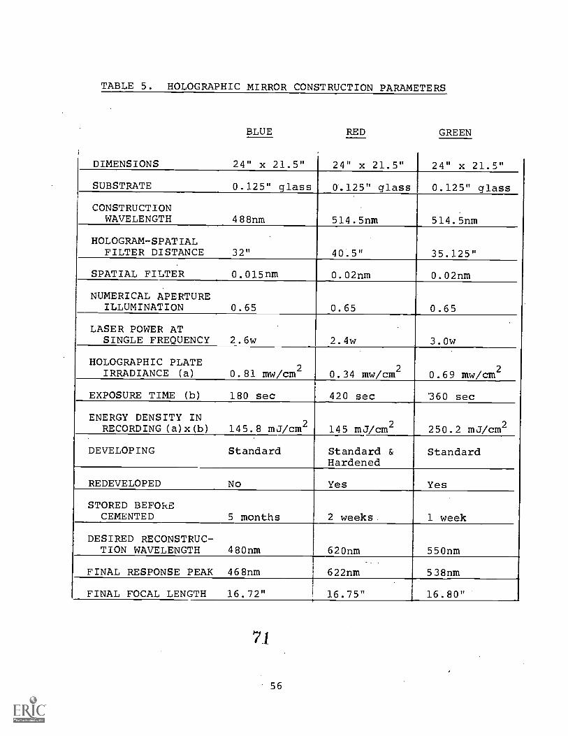
TABLE 5. HOLOGRAPHIC MIRROR CONSTRUCTION PARAMETERS
BLUE RED GREEN
DIMENSIONS 24" x 21.5" 24" x 21.5" 24" x 21.5"
SUBSTRATE 0.125" glass 0.125" glass 0.125" glass
CONSTRUCTIONWAVELENGTH 488nm 514.5nm 514.5nm
HOLOGRAM-SPATIALFILTER DISTANCE 32" 40.5" 35.125"
SPATIAL FILTER 0.015nm 0.02nm 0.02nm
NUMERICAL APERTUREILLUMINATION 0.65 0.65 0.65
LASER POWER ATSINGLE FREQUENCY 2.6w 2.4w 3.0w
HOLOGRAPHIC PLATEIRRADIANCE (a) 0.81 mw/cm 2
0.34 mw/cm20.69 mw/cm2
EXPOSURE TIME (b) 180 sec 420 sec 360 sec
ENERGY DENSITY INRECORDING(a)x(b) 145.8 mJ/cm 2 145 mJVcm 2 250.2 mJVcm2
DEVELOPING Standard Standard &Hardened
Standard
REDEVELOPED No Yes Yes
STORED BEFORECEMENTED 5 months 2 weeks week
DESIRED RECONSTRUC-TION WAVELENGTH 480nm 620nm 550nm
FINAL RESPONSE PEAK 468nm 622nm 538nm
FINAL FOCAL LENGTH 16.72" 16.75" 16.80"
71
56

SECTION VI
ASSEMBLY OF THE TRICOLOR HOLOGRAPHIC MIRRORAND PANCAKE WINDOW
Mirror Assembly
Each of the three mirrors was measured for spectralresponse and focal length. The spectral response wasdetermined photometrically measuring the reflection fromthe mirror of a monochromatic source. This source was amonochromator with a resolution of 2nm.
The radius of curvature of the mirrors was measuredmonochromatically and with a white light source. In bothcases a small point source was moved away or toward themirror until its reflected point image was at the sameplane as the source.
The mirrors were initially assembled "dry" and thereflected image of a 1951 USAF resolution chart was observedfor color rendition and superposition of the color images.When these were acceptable, the mirrors were aligned andcemented permanently.
The cementing structure consists of a platform whichwill support one of the mirrors. This platform is raisedand surrounded by a container structure which will col-lect the excess of cement and also support the alignmentscrews. Above this platform and at the focal plane ofthe mirrors is a long fluorescent tube, all blackenedwith the exception of three crosses, one at the centerand the other two symmetrically placed from the centerand separated by 16 inches.
While the cement is still very fluid, the second holo-gram is placed (with cement) over the immobile first one,and is translated with the alignment screws until thetwo color crosses are superimposed and the two colors fusein a color combination.
The red and blue holograms were cemented first, gel-atin to gelatin. The red hologram, which was the mostdifficult to produce, dictated the matching focal lengthfor the other two holograms.
57 72

The red hologram was considerably stronger (higher dif-raction efficincy) than the blue and the combination ofboth was magenta-reddish color. The superpo2itzn of thetwo color images was very good and only at extreme off-axisangles was a relative displacement noted. Also, becausethe two mirrors were practically in the same plane, and ofthe same focal length, the superposition of images was ob-servable even when the object wFzs not in the focal plane.
The green hologram was constructed to match this pairand corrected to have the same focal length min 1/8 inchwhich must be allowed for the substrate of one cf the othercemented holograms. Due to this difference in focal lengththe superposition of images was only observed_ when theobject.was placed at the focus.
When the images were superposed, especially at thecenter, the rendition of color was quite good and the.com-bination produced an acceptable white. At large off-axisangles, a displacement of the images was noticeable, andthis was primarily caused by a slight mismatch of thefocal lengths. Also the effect was more noticeable be-cause of the disparity of values of the hologram diffrac-tion efficiencies and because of the physical separationof the green hologram. Although the green hologram hasthe same focus, it has a different focal length whichcauses the images to be superposed only when collimated.
The green hologram was cemented to the red-blue pairwith the gelatin facing inside. The tricolor mirror wasin this way.protected by two of the glass substrates,all of the gelatins being inside the package.
The tricolor mirror produces a good color renditiondespite the placement of the holographic spectral re-sponse peaks, which were not at the designed values, andthe reflection intensities of the holograms, which wereless than optimum.
The resolution of the tricolor mirror was limited bythe resolution of the red hologram which was poor, es-pecially off-axis. The green and blue holograms had muchbetter resolution.
Tricolor Holographic Pancake Window Assembly
The holographic Pancake Window system also has an ad-vantage over the classical system in that it can be as-sembled in a single package. This is because the holo-graphic spherical tricolor mirror is physically flat andis cemented to the other elements of the package (i.e., alinear polarizer and a birefringent assembly).
7358

A consequence of this new configuration is the eliminationof two cover glasses with antireflection coatings, thepermanent alignment of the polarizer elements and the elim-ination of unwanted reflections between the three elementsof the classical Pancake Window system (Figure 2).
To assemble the holographic Pancake Window systemeach of its principal elements was prepared separately.The polarizer materials were seamed, stretched, and cem-ented to each of the two cover plate glasses which have ahigh efficiency antireflection coating. A seam was neces-sary because of the restricted width of the presently avail-able polarizer materials. The polarizers were cut andcemented to the glass plates in such a way that when as-sembled in the Pancake Window configuration, the polariza-tion axis will be crossed.
Another element is a plane beamsplitter mirror. Thisbeamsplitter is 1/8-inch thick and has a multilayer coatingwith a reflection of about 50 percent when it is cementedwith an adhesive of 1.5 index of refraction, and a trans-mission of approximately the same value. The absorptionof this plane beamsplitter is less than 2 percent. Cemen-ted to each side is a quarter-wave plate birefringent ma-terial. The quarter-wave plate materials are aligned withtheir retardation axes perpendicular, to each other and ata 450 angle to the linear axis of the polarizers. Thesequarter wave plate materials must also be seamed. Theyare selected by analyzing their retardance and pairingthe elements having the closest values, and closest to90 0 of retardation.
When these elements have been prepared, including theholographic tricolor mirror, they are assembled and photo-metrically aligned to obtain a minimum reading for thetransmitted unwanted light that is supposed to be sup-pressed by the polarizers.

SECTION VII
PERFORMANCE OF THE TRICOLOR WINDOW
The tricolor holographic Pancake Window was testedand measured for spectral response, spectral shift, mono-chromatic transmission,-white light transmission, reso-lution and collimation. It was visually tested as aninfinity optical display with color static and dynamicinput.
Spectral Response
The tricolor holographic Pancake Window has a tri-color composite holographic mirror with discrete spectralresponses. The three mirrors comprising the holographicmirror were originally designed to have a spectral peakresponse at 480nm, 555nm, and 620nm and a half-heightbandwidth response of about 30nm. For reasons explainedin this report, these initial values were not used, withlarge departures for the blue and the green response.This affected the transmission of the Pancake Window forphotopic white light input but does not appreciably dis-tort the rendition of color. The combination of thesemirrors produced a good white, as well as saturated colors.The orange -`red region of the spectrum was the one whichseemed to lose some fidelity in color transmission.
Figures 18, 19, and 20 represent the spectral dis-tribution for the three spectral regions vs. angle ofincidence. The illumination source was a monochromatorand the detector a photometer filtered for a photopicdistribution.
Figures 21, 22, and 23 represent the spectral dis-tribution of the three regions vs. field-of-view angle.
Figure 24 represents the spectral shift vs. thethree regions plotted in the same graph. The shift isthe same for field angles blow 15 but has a departurein the red for angles of 20 . This departure has not beenobserved in other cases and is still being analyzed.
Transmission
7560

470
460
450.
440
GEOMETRY: ()
MONOCHROMATOR PHOTOMETER
1
+20° +15° +10° +5o oo _50
ANGLE OF INCIDENCE
-10 -.150
FIGURE 18 WAVELENGTH PEAK Vs. ANGLE OF INCIDENCE (BLUE)
61
76
-20°

550
540
530
520
GEOMETRY: ()
1
MONOCHROMATOR PHOTOMETER
I \+20° +15° +10° +5o oo _50
ANGLE OF INCIDENCE
_100-15°
FIGURE 19. WAVELENGTH PEAK Vs. ANGLE OF INCIDENCE (GREEN)
62 7 7'
-20°

630
620
610
600
580
GEOMETRY: (---)
MONOCHROMATOR
1---
PHOTOMETER
+20° +15° +10° +500° -5°
ANGLE OF INCIDENCE
-10°
FIGURE 20. WAVELENGTH PEAK Vs. ANGLE OF INCIDENCE (RED)
63 78
-20°

CE
r- -.../ ..... ..,
I ---?
L.GEOMETRY: I-,
.--...
MONOCHROMATOIR1
480
470
460
450
440+20° +15° + 1 °
..)
C )
PHOTOMETER
+50 00-5°
FIELD OF VIEW ANGLE
- 1 -15° -20°
FIGURE 21. WAVELENGTH PEAK Vs. FIELD OF VIEW ANGLE (BLUE)
6479

560
550
540
530
520
r--
GEOMETRY: .MONOCHROMATOR
()
'PHOTOMETER
t
+200 +15° +10° +5o 0° -10° -15° -20°
FIELD OF VIEW ANGLE
FIGURE 22. WVELENGTH PEAK Vs. FIELD OF VIEW ANGLE (GREEN)
65 80

E
630
620
610
600
590
r-1
GEOMETRY:k, .1
T, 40-)
MONOCHROMATOR PHOTOMETER
1
f
+20° +15° +10° +5° 0° _50
FIELD OF VIEW ANGLE
-10° -15°
FIGURE 23. WAVELENGTH PEAK Vs. FIELD OF VIEW ANGLE (RED)
6681
-20°

10°
/5°
20°
SHIFT OF WAVELENGTH PEAK
WITH ANGLE OF INCITENCE
1.0-
I
lPHOTOPIC RESPOWF
7TR1CHROMATIC
PANCAKE WINDOW
RESPONSE
r-17----1--
450 460 470 480 490 500 510 520 530 540 550 560 570 580 590 600 610 620 630 640 650WAVELENGTH nm
FIGURE 24. SPECTRAL SHIFT Vs. COLOR AND
PHOTOPIC RESPONSE
82 83

The transmission values were: monochromatic red peaktransmission, 0.44 percent; monochromatic green peak trans-mission, 0.76 percent; monochromatic blue pea } - transmission,0.25 percent; and white-light transmission, 0.125 percent.These values departed considerably from the design valuesbecause of the effort to match the focal lengths and be-cause of time and funding limitations.
The reflectivity (diffraction efficiency of the holo-graphic mirror) was not maximized to 50 percent. This isnot a technological limitation in the sense that most ofthe experimentally produced beamsplitters have a diffrac-tion efficiency higher than 50 percent. However, for abroad band spectral input, a reflectivity smaller than50 percent is required to avoid double image (double spec-tral peak) transmission.
This happens because the Pancake Window will have amaximum transmission when the reflectivities of each ofthe two beamsplitters equals 50 percent. For lower orhigher values, the transmission will be lower. If thespectral response of the beamsplitter is not flat and thereflectivity at the spectral peak is higher than 50 per-cent, then the Pancake Window will have a maximum trans-mission not at the spectral peak but for the two pointsin the. spectral reflectivity curve whose values are 50percent. These double transmission peaks will produce adoubling of images (because of the focal length - wave-length dependence) and deteriorate the resolution of thesystem. Consequently, and due to time limitations, theholograms were produced with emphasis on avoiding theseproblems and Ar_)t on maximizing the transmission of thePancake Window.
The three spectral peaks departed from the designedvalues. When the transmission is measured with relationto the photopic visual response, the values are abnormallylow. Figure 15 shows how inefficiently the photopic spec-tral region is covered oy the three spectral peaks.
With holographic mirrors having better constructionparameters, monochromatic transmissions over 1.2 percentand white light transmission closer to 1 percent should beexpected.
In the monochromatic system, it will be required thatthe spectral widt -h of the source be no greater than thespectral response of the holograms. For this area, thetransmission will be similar to that of the classicalPancake Window (1.2 percent) or higher as we have exper-imentally measured it. For a white light broad bandspectral source, the spectral response of each of thethree color holograms must be chosen to maximize the
8468

coverage over the photopic curve. A compromise must bemade between maximum coverage and widening of the spectralpeak which will produce color dispersion.- For a 30nm half-peak intensity bandwidth am with the holograms spectralpeaks centered at 510nm, 55Dnm, and 600nm the photopicarea will be covered by about 75 percent and the transmis-sion will be 0.75 x 1.2 = 0.9 percent.
Resolution
The resolution has been measured using monochromaticsources and white-light illumination. The resolution tar-get was a USAF 1951 Resolution Chart placed at the focalplane of the mirror or projected on a screen placed atthis focal plane. The image of the resolution chart wasviewed with a 3x magnification telescope from the pupilof the Holographic Pancake Window (Tables 6, 7, and .8).
8569

MonochromaticSource withUSAF 1951Resolution
;)
/
Chart4- r
I
TricolorPancake WindowTM
15k'-'1"4-1°----- 24L
3X Dioptometer
) Center of Pupil
RESOLUTION (MINUTES OF ARC)-HORIZC7TAL SCAN
Wavelength3X Diotometer
Vertical Horizontal
538nm (w/5nm slit) 2-6(1.13) 2-6(1-3)
538nm (no slit) 2-6(1.13) 2-6(1.13).
oo
624nm (w/5nm slit) 2-6(1.13) . 2-6(1.13)
0o 467nm (no slit) (Not Enough Light)
+5o
538nm (no slit) 0-6(4.52)1
2-1(2.01)
+° 624nm (no slit) 0-6(4.52) 2-1(2.01)
+10o
533NR (no snt) - 1-4(2.83)
+10. r-.
E24nm (no slit) 1-4(2,83)
RESOLUTION WITH MONOCHROMII:IC SOURCE VS. FIELD OF VIEW ANGLE
TABLE 6

WhiteFlourescentSourceIlluminatingUSAF 1951ResolutionChart
TricolorPancake Wir,Awrm
15 "
RESOLUTION (MINUTES
- 3X Dioptometer
I+ 'Entrance Aperture
1 12.5mm
24"
Center of Pupil
OF ARC)- HORIZONTAL SCAN
3X Dioptometer
Horizontal Vertical Hor. & Vert.
oo
2-6(1.13) 2-6(1.13) 2-6(1.13)
1-6(2.26) 1-1(4.03) 1-1(4.03)
+10° 1-1(4.03) 1-3(12.7) 1-3(12.7)
+15° 0-1(8.06) 2-3(25.4) 2-3(25.4)
+20° 0-1(8.06) 2-2(28.7) 2-2(28.7)
+25° - - -
_501-1(4.03) 0-1(8.06) 0-1(8.06)
-10° 1-1th.03) 2-6(18.1) 2-6(18.1)
-15° 0-1(8.06) 2-6(18.1) 1 2-6(18.1)
-20o
0-1(8.06) 2-3(25.) J 2-3(25.4)
RESOLUTION WITH WHITE SOURCE VS. FIELD OF VIEW ANGLE
TABLE 7
71 87

Projector
^
19" ROC
ScreenTricolor
Pancake Window"
USAF 1951Resolution ChartMagnified 0-11 Unit = 1.4cm
154i'
20"
22"
RESOLUTION*(MINUTES OF ARC)-HORIZONTAL SCAN
Field of View Anglee°
3X Dioptometer Lyevertical- Horizontal Vertical Horizontal
0° 5-3(2.77) 5-3(2.77) 4-3(5.55) 4-3(5.55)
+5° 3-4(9.9) 4-2(6.23) 4-3(5.55) 4-3(5.55)
+10° 2-6(15.8) 4-1(7.05) 2-6(15.8) 3-4(9.9)
+15° 2-5(17.6)
L
3-5(8.82) 2-5(17.6) 3-3(11.1)
+20° 2-1(28.2) 3-4(9.9) 2-3(22.2) 3-2(12.5)
+25° 1-409.6) 2-2(25.1) 1-5(35.3) 2-6(15.8)
-z ,
4-1(7.05) 4-54.41) 3-6(7.91) 4-2(6.23)
-107' 3-1(14.1) 4-1(7.05) 3-1(14.1) 3-4(9.9)
-15o2-1(28.2) 3-3(11.1) 2-2(25.1) 3-3(11.1)
-20° 2-1(28.2) 2-6(15.8) 2-1(28.2) 3-1(14.1)
-25° 1- 5(31.6) 2-6(15.8)
* USAF 1951 Resolution Chart was magnified by projection on a screen. In the 0-1group 1 unit (a line and adjacent space) equaled 1.4cm.
RESOLUTION* WITH WHITE PROJECTOR SOURCE VS. FIELD OF VIEW ANGLE
TABLE 8 _

SECTION VIII
CONCLUSIONS AND RECOMMENDATIONS
This project succeeded in demonstrating the feasibilityof producing a holographic compound spherical beamsplittermirror with full color response. Furthermore, this holo-graphic beamsplitter was incorporated into a Pancake Win-dow display system as a replacement for the classicalglass spherical beamsplitter and its performance andcolor capabilities have been demonstrated.
Solutions to certain problems were expected to havebeen achieved prior to this effort. These problems in-cluded the folliowing:
1. The control of the monochromatic wavelength re-sponse with respect to its exact spectral position.
2. The spectral peak response stability.
3. The improvement of the holographic off-axis re-solution.The fact that these areas were still unresolved required
expenditure of effort in these directions early inthe program, thereby reducing both the time and effortavailable to achieve the specific goals of this program.
T'.: 2roduction of a red hologram utilized most of theprograN,s efforts and became critical in proving the feasi-bility ^f the project. Early portion successful resultsled to false appraisal of the overall difficulty of theproblem.
In the context of design goals, all the bask problemshave been resolved with the exception of the resolution ofthe red hologram needs further development off-axis.The poor resolution r:f the red hologram was more apparentthan real due to the use of a broad band fluorescent sourceto illuminate the Air. Force resolutthn target. This sourcehas narrow mercury line spikes which enhance the resolutionof the blue and green holograms, with regard to color dis-persion, but not the red hologram.
The poor performance with respect to some -tion goals is attributed to poor manufacturing' calibrat.ion

or short manufacturing time, but not to basic or inherentproblems.
One of these specification goals, the transmission ofthe Pancake Window was not limited by inherent or designproblems but its very low value is due to low diffractionefficiency and wrong positioning of the wavelength responsepeak under the photopic visual curve (Figure 23). Thesepoor characteristics (which can be improved without fur-ther research) were ignored in favor of achieving a goodfocal length match and completing the project within therequired time frame. (Around 1.2 percent for monochromaticsources and 0.9 percent for broad band sources, as was ex-plained in Section VII).
Within the prese4t state-of-the-art, it will be pos-sible to produce a tricolor Holographic Pancake Windowwith a white-light transmission of approximately 1 percent.
The resolution of the red hologram needs to be improved,and the relationship between construction wavelength andresoilltion has still to be determined. The wavelength shiftrequired using the argon laser is much greater than usingthe krypton laser, but the holographic process is more ad-vanced for the green wavelength of the argon ion laser thanfor the red wavelength of the krypton laser.
Continued development is recommended to improve theresolution of the red hologram and to establish any pos-sible limitation in the use of the argon or the kryptonlaser to produce the red hologram.
It is further recommended that other tricolor windowsbe made with the present technology giving emphasis to thequality of tine product, especially to wavelength peak pos-ition and diffraction efficiency which will markedly im-pro,.e the transmission of the Pancake Window. Also, rec-ommended is the elimination of cosmetic defects, exact fo-cal length matching, and cementing the three holographicfilms without any substrate separation.
This new window could provide more precise evaluationdata for comparison with a classical system to the moststringent parameters. Areas which will require furtherdevelopment could then_be more accurately established.
The holographic facilities failed to provide con-trolled environment (specifically humidity) in very dryor very humid outside air conditions. The capacitiesof humidifiers and dehumidifiers were not sufficient tohandle the large volume of air required for the cleanrooms, especially because they had a common air circu-lating system.
9074

The common air circulating system was designed as thesimplest way to achieve the same environment in all therooms, but individual systems for each room are now recom-mended to reduce the volume of air which must be handledwith stan'ard clean room "air make up" systems.
975

APPENDIX A
HOLOGRAPHIC FACILITIES
The holographic facility is located in the basement of oneof thecontracor's buildings. The three most importantthings which were considered in its design were:-
1. Control of environmental parameters (humidityand temperature).
2. Clean room facilities.
3. Insulation from vibration and noise.
Figure A-1 shows an overhead schematic representationof the facilities. It is important to note that, althoughthere is a different room for each different process, allrooms are clean rooms of class 10,000, and all have thesame temperature and air humidity.
In the entrance and office rooms, the personnel equipthemselves to enter the clean rooms. All the glass andmaterial is stored and precleaned in this room.
The chemical room has the facilities and space toprepare the gelatin solutions and for the last cleaningof the plates which will be coated. The coating booth inthis room is a class 100 booth with control for air speedcirculation, ail temperature and air humidity. Also inthis room is a desiccator booth which also has humidityand temperature controls.
The next roon is called the laser room which is alsoused for testing and photometric (angular andwavelength response of the holographic plates).
A light-proof door leads to the holographic room' and/or to the developing room and photosensitizing room.
Environment Control. The air is recirculated, withabout a 20-percent air intake of outside --air, which is ata constant. 62°F temperatu.m The air is circulated at aspeed sufficient to produ a complete change of airevery 2 minutes in all the rooms. The system is provided
76

EVALUATION AREA
DESICCATOR
BOOTH
ENTRANCE ROOM
OFFICE
93
LASER ROOM
INSULATED
HOLOGRAPHIC
ROOM
DEVELOPING
ROOM
PHOTO-SENSITIZING
ROOM
COATING
BOOTH
CHEMICAL ROOM
PRESSURE
TEMPERATURE r CONTROLS
HUMIDITY j
FIGURE A-1, HOLOGRAPHIC FACILITY
94

with heaters, humidifier and dehumidifiers. The rooms havetemperature control which automatically maintains :_he se-lected temperature to +10C. They have a humidistat whichautomatically controls relative humidity by means of hu-midifiers and dehumidifiers. They also have an air pres-sure control which automatically closes or opens the ex-haust damper to produce a positive pressure inside theclean rooms at all times (Figure A-2).
Conditioro:hi air is introduced in each room through 99.9percent absolute filters in the ceiling which will filterpractically all particles larger than 0.3mu. This airwill sweep tLrough the rooms and reliurn by the grillssituated close to floor level and opposite the filters.The return air is mixed in the ducts providing identicalair quality for all the rooms. The normal exhaust air isused to climatize the entrance room before being exhaustedoutside. The rooms also have independent emergency ex-haust systems in the holographic room, developing room,and desiccator booth. These fxhar::.:ts are routinely usedto avoid unhealthy concentratIons of volatile chemicals.
A remote control damp:. :I insulate the holographicroom to avoid any air circ. A during holographic ex-posures.
The coating booth, Fiq-urc A-3, is a class 100 clean.booth (no more than 100 particles larger than 0.3 micro-meters per cubic foot). has a rotating table whichoperates at 1 rpm and 4:.'c. is Placed the plate tobe coated. This booth a germicide short ultravioletlight, a heater, and a humidifier. It has a reservoir ofdistilled water and has two circulating fans: one forhigh volume and other other for a very small volume ofcirculation. Each of these fans is of continuously vari-able speed. The booth can also be sealed from the air inthe room.
This booth was fabricated of stainless steel and hasa capacity for plates to 36 inches in diameter.
Once the glass plate is introduced in the booth, itis discharged of any static buildup by blowing it withdry nitrogen from a radioactive antistatic gun. The airis circulating at a maximum speed sweeping the booth clean.After awhile, the high volume circulation is redUced, theplate is coated, and the coating parameters are adjustedto obtain the Cesired flatness and hardness. Dependingon the gelatin coating solution formulation,. flat platescan be produced in from 8 hours drying time to 48 hours,after which the growth of bacteria must be avoided.


REMOTE CONTROL DAMPER
DEHUMIDI,F1ER--\
HEATER,---//
HUMIDIFIER .
8 RECIRCULATING
FAN
96
20% EXHAUST-/
EMERGENCY
EXHAUST OUT
N-DEHUMIDIFIER
PRESSURE CONTROLLED
EXHAUST
FIGURE A-2. HOLOGRAPHIC FACILITIES:
AIR CIRCULATION SYSTEM 97

The laser room has an air-mishioned table which sup-ports a 20-watt all-lines argon ion laser and a 2-watt all-lines Coherent Radiation laser, Figure A-4. The 20-wattlaser operated with an etalon provides about 5 watts ofsingle line TEMoo operation in the 514.5nm line or in the488.1nm line. The operation of the laser is monitoredwith a scanning etalon whose output is displayed on anoscilloscope. The etalon has a spectral free range of2,000 MHz and the bandwidth of the laser line displayedis around 50MHz. The minimum separation of the trans-versal modes for the 20 watt laser is 70MHz. These lasersare water-cooled, and an expansion tank is used to dampenvariations in water pressure.
Due to the considerable noise and heat produced bythe power supply of this large laser, a pioneering tech-nique of having the laser in a separate room adjacent tothe room which has the holographic table was successfullyused. The laser beams are sent through a 0.5-inch diametertubular hole in the partition wall. In this wall, thereis also a conical visual port to permit observation ofthe holographic table, and a port-lens system to displayinterference fringes from vibration monitoring inter-feroMeters.
The holographic room is insulated with an extra wallof noise-insulating material and a double, nylon-cord.su-spended ceiling. The holographic table is a granite slab48 inches x 70 inches x 10 inches supported by air tubes.The mirror, originally mounted on the table, is an alum-inized. glass mirror with a 48-inch radius of curvature and40-inch x 38-inch aperture, Figure A-5. The mirror isdamped at the supporting base and at its back with smallplastic bags filled with sand (about 200 kg of sand).
The first experimental wet cell, used to eliminateunwanted reflections, had windows coated with high ef-ficiency AR glass which has a thickness of 3/8 inch. Thiswet cell is useful for plates with a maximum size of 24inches x 21.5 inches, Figure 21.
For stability reasons, the master mirror and wet cellgeometry were modified to the horizbntal wet cell geometry,Figure 17.
A 3mW "helium-neon" laser is used to monitor vibra-tion in the wet cell or in the mirror after the photosensi-tized plate is in place for exposure but before it isexposed.
The developing room has a supply of demineralizedwater whose temperature is controlled to +1/2°C. Thewashing tank, which can be used for plates to 36 inches in
818
diameter, has multiple shower heads, control of water level,exhaust through the bottom and a rotating inner tank drivenby a small motor, Figure A-6.
This room connects through a window to the desiccatorboOth where the plates are dried after development.
Figure A-7 shows the holographic beamsplitter mirroranalyzer. The monochromator with a resolution of 10 A il-luminates the holographic plate through a collimating lens.The light reflected at the mirror is focused at the windowof a photocell. A system of gears automatically displacesthe photocell for each angle of incidence. This instru-ment provides a fast analysis of the wavelength andangular response of the holograms.
99
84

REFERENCES
1 Development of a 17-inch aoerture, holographic volume -phase, on-axis spherical beampslitter mirror. AFHRL-TR-78-29,1D-A058 339. Wright-Patterson AFB, Ohio, Ausust 1978.
2 Low cost, Wide Angle, Infinite Optics Visual DisplayFinal Technical Reports.
3 Holographic lens for pilot's head up display Phase IIIby A. Au, A. Graube and L.G. Cook NADC-75293-30.
4 Optical Holographic by Collier, Burchardt and Lin.Academic Press 1971.
5 The theory of the Photographic Process by E. Messand T. James, Macmillan Co., 1966.
10087